WO2020241234A1 - 電子機器、電子機器の制御方法、及びプログラム - Google Patents
電子機器、電子機器の制御方法、及びプログラム Download PDFInfo
- Publication number
- WO2020241234A1 WO2020241234A1 PCT/JP2020/018946 JP2020018946W WO2020241234A1 WO 2020241234 A1 WO2020241234 A1 WO 2020241234A1 JP 2020018946 W JP2020018946 W JP 2020018946W WO 2020241234 A1 WO2020241234 A1 WO 2020241234A1
- Authority
- WO
- WIPO (PCT)
- Prior art keywords
- electronic device
- signal
- control unit
- distance
- unit
- Prior art date
- Legal status (The legal status is an assumption and is not a legal conclusion. Google has not performed a legal analysis and makes no representation as to the accuracy of the status listed.)
- Ceased
Links
Images


Classifications
-
- G—PHYSICS
- G01—MEASURING; TESTING
- G01S—RADIO DIRECTION-FINDING; RADIO NAVIGATION; DETERMINING DISTANCE OR VELOCITY BY USE OF RADIO WAVES; LOCATING OR PRESENCE-DETECTING BY USE OF THE REFLECTION OR RERADIATION OF RADIO WAVES; ANALOGOUS ARRANGEMENTS USING OTHER WAVES
- G01S13/00—Systems using the reflection or reradiation of radio waves, e.g. radar systems; Analogous systems using reflection or reradiation of waves whose nature or wavelength is irrelevant or unspecified
- G01S13/02—Systems using reflection of radio waves, e.g. primary radar systems; Analogous systems
- G01S13/50—Systems of measurement based on relative movement of target
- G01S13/52—Discriminating between fixed and moving objects or between objects moving at different speeds
- G01S13/536—Discriminating between fixed and moving objects or between objects moving at different speeds using transmission of continuous unmodulated waves, amplitude-, frequency-, or phase-modulated waves
-
- G—PHYSICS
- G01—MEASURING; TESTING
- G01S—RADIO DIRECTION-FINDING; RADIO NAVIGATION; DETERMINING DISTANCE OR VELOCITY BY USE OF RADIO WAVES; LOCATING OR PRESENCE-DETECTING BY USE OF THE REFLECTION OR RERADIATION OF RADIO WAVES; ANALOGOUS ARRANGEMENTS USING OTHER WAVES
- G01S13/00—Systems using the reflection or reradiation of radio waves, e.g. radar systems; Analogous systems using reflection or reradiation of waves whose nature or wavelength is irrelevant or unspecified
- G01S13/02—Systems using reflection of radio waves, e.g. primary radar systems; Analogous systems
- G01S13/06—Systems determining position data of a target
- G01S13/08—Systems for measuring distance only
- G01S13/32—Systems for measuring distance only using transmission of continuous waves, whether amplitude-, frequency-, or phase-modulated, or unmodulated
- G01S13/34—Systems for measuring distance only using transmission of continuous waves, whether amplitude-, frequency-, or phase-modulated, or unmodulated using transmission of continuous, frequency-modulated waves while heterodyning the received signal, or a signal derived therefrom, with a locally-generated signal related to the contemporaneously transmitted signal
- G01S13/343—Systems for measuring distance only using transmission of continuous waves, whether amplitude-, frequency-, or phase-modulated, or unmodulated using transmission of continuous, frequency-modulated waves while heterodyning the received signal, or a signal derived therefrom, with a locally-generated signal related to the contemporaneously transmitted signal using sawtooth modulation
-
- G—PHYSICS
- G01—MEASURING; TESTING
- G01S—RADIO DIRECTION-FINDING; RADIO NAVIGATION; DETERMINING DISTANCE OR VELOCITY BY USE OF RADIO WAVES; LOCATING OR PRESENCE-DETECTING BY USE OF THE REFLECTION OR RERADIATION OF RADIO WAVES; ANALOGOUS ARRANGEMENTS USING OTHER WAVES
- G01S13/00—Systems using the reflection or reradiation of radio waves, e.g. radar systems; Analogous systems using reflection or reradiation of waves whose nature or wavelength is irrelevant or unspecified
- G01S13/02—Systems using reflection of radio waves, e.g. primary radar systems; Analogous systems
- G01S13/50—Systems of measurement based on relative movement of target
- G01S13/58—Velocity or trajectory determination systems; Sense-of-movement determination systems
- G01S13/583—Velocity or trajectory determination systems; Sense-of-movement determination systems using transmission of continuous unmodulated waves, amplitude-, frequency-, or phase-modulated waves and based upon the Doppler effect resulting from movement of targets
- G01S13/584—Velocity or trajectory determination systems; Sense-of-movement determination systems using transmission of continuous unmodulated waves, amplitude-, frequency-, or phase-modulated waves and based upon the Doppler effect resulting from movement of targets adapted for simultaneous range and velocity measurements
-
- G—PHYSICS
- G01—MEASURING; TESTING
- G01S—RADIO DIRECTION-FINDING; RADIO NAVIGATION; DETERMINING DISTANCE OR VELOCITY BY USE OF RADIO WAVES; LOCATING OR PRESENCE-DETECTING BY USE OF THE REFLECTION OR RERADIATION OF RADIO WAVES; ANALOGOUS ARRANGEMENTS USING OTHER WAVES
- G01S7/00—Details of systems according to groups G01S13/00, G01S15/00, G01S17/00
- G01S7/02—Details of systems according to groups G01S13/00, G01S15/00, G01S17/00 of systems according to group G01S13/00
- G01S7/35—Details of non-pulse systems
- G01S7/352—Receivers
- G01S7/354—Extracting wanted echo-signals
-
- G—PHYSICS
- G01—MEASURING; TESTING
- G01S—RADIO DIRECTION-FINDING; RADIO NAVIGATION; DETERMINING DISTANCE OR VELOCITY BY USE OF RADIO WAVES; LOCATING OR PRESENCE-DETECTING BY USE OF THE REFLECTION OR RERADIATION OF RADIO WAVES; ANALOGOUS ARRANGEMENTS USING OTHER WAVES
- G01S13/00—Systems using the reflection or reradiation of radio waves, e.g. radar systems; Analogous systems using reflection or reradiation of waves whose nature or wavelength is irrelevant or unspecified
- G01S13/88—Radar or analogous systems specially adapted for specific applications
- G01S13/93—Radar or analogous systems specially adapted for specific applications for anti-collision purposes
- G01S13/931—Radar or analogous systems specially adapted for specific applications for anti-collision purposes of land vehicles
Definitions
- This disclosure relates to electronic devices, electronic device control methods, and programs.
- radar Radio Detecting and Langing
- RADAR Radio Detecting and Langing
- Techniques have been studied in various ways. The importance of technology for measuring such distances will increase in the future with the development of technology that assists the driver's driving and technology related to autonomous driving that automates part or all of the driving. is expected.
- Patent Document 1 irradiates a target object with a transmission signal that has undergone linear FM modulation at a specific cycle, detects a beat signal based on the difference from the reception signal from the target object, and analyzes the frequency and speed of this signal. It discloses an FM-CW radar device that performs measurement.
- the electronic device includes a transmitting antenna for transmitting a transmitted wave, a receiving antenna for receiving the reflected wave reflected by the transmitted wave, and a control unit.
- the control unit detects the target with a constant false alarm probability based on the transmission signal transmitted as the transmission wave and the reception signal received as the reflected wave.
- the control unit intermittently provides a reference region in the distance direction and the relative velocity direction with reference to the inspection region.
- a threshold used for detecting the target is set based on an order statistic of signal strength in the reference region.
- the electronic device control method includes the following steps. (1) Step of transmitting the transmitted wave from the transmitting antenna (2) Step of receiving the reflected wave reflected by the transmitted wave from the receiving antenna (3) The transmitted signal transmitted as the transmitted wave and received as the reflected wave Step of detecting a target with a constant false alarm probability based on the received signal (4) In the two-dimensional distribution of the signal strength based on the received signal in the distance direction and the relative velocity direction, the distance direction with respect to the inspection area. And a step of intermittently providing a reference region in the relative velocity direction (5) a step of setting a threshold value used for detecting the target based on the ordinal statistics of the signal strength in the reference region.
- the program causes a computer to execute the above steps (1) to (5).
- An object of the present disclosure is to provide an electronic device, a control method for the electronic device, and a program capable of improving the accuracy of detecting a target. According to one embodiment, it is possible to provide an electronic device, a control method for the electronic device, and a program that can improve the accuracy of detecting a target.
- the electronic device according to the embodiment By mounting the electronic device according to the embodiment on a vehicle (moving body) such as an automobile, it is possible to detect a predetermined object existing around the moving body as a target. Therefore, the electronic device according to the embodiment can transmit a transmitted wave around the mobile body from a transmitting antenna installed on the mobile body. Further, the electronic device according to the embodiment can receive the reflected wave in which the transmitted wave is reflected from the receiving antenna installed in the mobile body. At least one of the transmitting antenna and the receiving antenna may be provided in, for example, a radar sensor installed in a moving body.
- the electronic device according to one embodiment is mounted on an automobile such as a passenger car.
- the electronic device according to the embodiment is not limited to the automobile.
- the electronic devices according to one embodiment are used for various moving objects such as agricultural work devices such as buses, taxis, trucks, motorcycles, bicycles, ships, aircraft, helicopters, tractors, snowplows, cleaning vehicles, police cars, ambulances, and drones. It may be installed.
- the electronic device according to the embodiment is not necessarily mounted on a moving body that moves by its own power.
- the moving body on which the electronic device according to the embodiment is mounted may be a trailer portion towed by a tractor.
- the electronic device can measure the distance between the sensor and the object in a situation where at least one of the sensor and a predetermined object can move. Further, the electronic device according to the embodiment can measure the distance between the sensor and the object even if both the sensor and the object are stationary.
- FIG. 1 is a diagram illustrating a usage mode of the electronic device according to the embodiment.
- FIG. 1 shows an example in which a sensor including a transmitting antenna and a receiving antenna according to an embodiment is installed on a moving body.
- the mobile body 100 shown in FIG. 1 is provided with a sensor 5 including a transmitting antenna and a receiving antenna according to the embodiment. Further, it is assumed that the mobile body 100 shown in FIG. 1 is equipped (for example, built-in) with the electronic device 1 according to the embodiment. The specific configuration of the electronic device 1 will be described later.
- the sensor 5 may include, for example, at least one of a transmitting antenna and a receiving antenna. Further, the sensor 5 may appropriately include at least one of other functional units such as at least a part of the control unit 10 (FIG. 2) included in the electronic device 1.
- the moving body 100 shown in FIG. 1 may be an automobile vehicle such as a passenger car, but may be any type of moving body. In FIG. 1, the moving body 100 may, for example, move (run or slow) in the positive direction (traveling direction) of the Y axis shown in the figure, move in another direction, or move. It may be stationary without.
- a sensor 5 provided with a transmitting antenna is installed in the moving body 100.
- only one sensor 5 including a transmitting antenna and a receiving antenna is installed in front of the moving body 100.
- the position where the sensor 5 is installed on the moving body 100 is not limited to the position shown in FIG. 1, and may be another position as appropriate.
- the sensor 5 as shown in FIG. 1 may be installed on the left side, the right side, and / or the rear of the moving body 100.
- the number of such sensors 5 may be any one or more depending on various conditions (or requirements) such as the measurement range and / or accuracy of the moving body 100.
- the sensor 5 may be installed inside the moving body 100.
- the inside of the moving body 100 may be, for example, a space in a bumper, a space in a body, a space in a headlight, a space in a driving space, or the like.
- the sensor 5 transmits an electromagnetic wave as a transmission wave from the transmission antenna. For example, when a predetermined object (for example, the object 200 shown in FIG. 1) exists around the moving body 100, at least a part of the transmitted wave transmitted from the sensor 5 is reflected by the object to become a reflected wave. Then, by receiving such a reflected wave by, for example, the receiving antenna of the sensor 5, the electronic device 1 mounted on the moving body 100 can detect the object as a target.
- a predetermined object for example, the object 200 shown in FIG. 1
- the sensor 5 provided with a transmitting antenna may typically be a radar (RADAR (Radio Detecting and Ringing)) sensor that transmits and receives radio waves.
- RADAR Radio Detecting and Ringing
- the sensor 5 is not limited to the radar sensor.
- the sensor 5 according to one embodiment may be, for example, a sensor based on the technology of LIDAR (Light Detection and Ringing, Laser Imaging Detection and Ringing) using light waves.
- LIDAR Light Detection and Ringing, Laser Imaging Detection and Ringing
- a sensor such as these can be configured to include, for example, a patch antenna. Since technologies such as RADAR and LIDAR are already known, detailed description may be simplified or omitted as appropriate.
- the electronic device 1 mounted on the mobile body 100 shown in FIG. 1 receives the reflected wave of the transmitted wave transmitted from the transmitting antenna of the sensor 5 from the receiving antenna. In this way, the electronic device 1 can detect a predetermined object 200 existing within a predetermined distance from the moving body 100 as a target. For example, as shown in FIG. 1, the electronic device 1 can measure the distance L between the moving body 100, which is the own vehicle, and the predetermined object 200. The electronic device 1 can also measure the relative speed between the moving body 100, which is its own vehicle, and the predetermined object 200. Further, the electronic device 1 can also measure the direction (arrival angle ⁇ ) at which the reflected wave from the predetermined object 200 reaches the moving body 100 which is the own vehicle.
- the object 200 is, for example, at least one of an oncoming vehicle traveling in a lane adjacent to the moving body 100, a vehicle running in parallel with the moving body 100, and a vehicle before and after traveling in the same lane as the moving body 100.
- the object 200 is a moving object such as a motorcycle, a bicycle, a stroller, a pedestrian or other human being, an animal, an insect or other life form, a guardrail, a median strip, a road sign, a step on a sidewalk, a wall, a manhole, or an obstacle. It may be any object that exists around the body 100. Further, the object 200 may be moving or may be stationary. For example, the object 200 may be an automobile parked or stopped around the moving body 100.
- the ratio between the size of the sensor 5 and the size of the moving body 100 does not necessarily indicate the actual ratio.
- the sensor 5 is shown in a state of being installed outside the moving body 100.
- the sensor 5 may be installed at various positions on the moving body 100.
- the sensor 5 may be installed inside the bumper of the moving body 100 so as not to appear in the appearance of the moving body 100.
- the transmitting antenna of the sensor 5 will be described as transmitting radio waves in a frequency band such as millimeter waves (30 GHz or more) or quasi-millimeter waves (for example, around 20 GHz to 30 GHz).
- the transmitting antenna of the sensor 5 may transmit radio waves having a frequency bandwidth of 4 GHz, such as 77 GHz to 81 GHz.
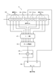
- FIG. 2 is a functional block diagram schematically showing a configuration example of the electronic device 1 according to the embodiment.
- FIG. 2 is a functional block diagram schematically showing a configuration example of the electronic device 1 according to the embodiment.
- an example of the configuration of the electronic device 1 according to the embodiment will be described.
- FMCW radar Frequency Modified Continuous Wave radar
- the FMCW radar sweeps the frequency of the radio wave to be transmitted to generate a transmission signal. Therefore, in a millimeter-wave FMCW radar that uses radio waves in the frequency band of 79 GHz, for example, the frequency of the radio waves used has a frequency bandwidth of 4 GHz, for example, 77 GHz to 81 GHz. Radars in the 79 GHz frequency band are characterized by a wider usable frequency bandwidth than other millimeter-wave / quasi-millimeter-wave radars, such as the 24 GHz, 60 GHz, and 76 GHz frequency bands.
- such an embodiment will be described as an example.
- the electronic device 1 is composed of a sensor 5 and an ECU (Electronic Control Unit) 50.
- the ECU 50 controls various operations of the moving body 100.
- the ECU 50 may be composed of at least one or more ECUs.
- the electronic device 1 according to the embodiment includes a control unit 10. Further, the electronic device 1 according to the embodiment may appropriately include other functional units such as at least one of the transmission unit 20, the reception units 30A to 30D, and the storage unit 40.
- the electronic device 1 may include a plurality of receiving units, such as the receiving units 30A to 30D.
- the receiving unit 30A, the receiving unit 30B, the receiving unit 30C, and the receiving unit 30D are simply referred to as "reception unit 30".
- the control unit 10 may include a distance FFT processing unit 11, a speed FFT processing unit 12, a distance speed detection determination unit 13, an arrival angle estimation unit 14, and an object detection unit 15. These functional units included in the control unit 10 will be further described later.
- the transmission unit 20 may include a signal generation unit 21, a synthesizer 22, phase control units 23A and 23B, amplifiers 24A and 24B, and transmission antennas 25A and 25B.
- phase control unit 23A and the phase control unit 23B are not distinguished, they are simply referred to as "phase control unit 23".
- amplifier 24A and the amplifier 24B are not distinguished, they are simply referred to as "amplifier 24”.
- transmitting antenna 25A and the transmitting antenna 25B are not distinguished, they are simply referred to as "transmitting antenna 25".
- the receiving unit 30 may be provided with corresponding receiving antennas 31A to 31D, respectively.
- each of the plurality of receiving units 30 may include an LNA 32, a mixer 33, an IF unit 34, and an AD conversion unit 35, respectively, as shown in FIG.
- the receiving units 30A to 30D may have the same configuration. In FIG. 2, as a typical example, the configuration of only the receiving unit 30A is schematically shown.
- the sensor 5 described above may include, for example, a transmitting antenna 25 and a receiving antenna 31. Further, the sensor 5 may appropriately include at least one of other functional units such as the control unit 10.
- the control unit 10 included in the electronic device 1 can control the operation of the entire electronic device 1 including the control of each functional unit constituting the electronic device 1.
- the control unit 10 may include at least one processor, such as a CPU (Central Processing Unit), in order to provide control and processing power for executing various functions.
- the control unit 10 may be realized collectively by one processor, by several processors, or by individual processors.
- the processor may be implemented as a single integrated circuit.
- the integrated circuit is also called an IC (Integrated Circuit).
- the processor may be implemented as a plurality of communicably connected integrated circuits and discrete circuits.
- the processor may be implemented on the basis of various other known techniques.
- the control unit 10 may be configured as, for example, a CPU and a program executed by the CPU.
- the control unit 10 may appropriately include a memory necessary for the operation of the control unit 10.
- the storage unit 40 may store the program executed by the control unit 10, the result of the processing executed by the control unit 10, and the like. Further, the storage unit 40 may function as a work memory of the control unit 10.
- the storage unit 40 can be configured by, for example, a semiconductor memory, a magnetic disk, or the like, but is not limited to these, and can be any storage device. Further, for example, the storage unit 40 may be a storage medium such as a memory card inserted in the electronic device 1 according to the present embodiment. Further, the storage unit 40 may be the internal memory of the CPU used as the control unit 10 as described above.
- the storage unit 40 may store various parameters for setting a range for detecting an object by the transmission wave T transmitted from the transmission antenna 25 and the reflected wave R received from the reception antenna 31.
- the control unit 10 can control at least one of the transmission unit 20 and the reception unit 30.
- the control unit 10 may control at least one of the transmission unit 20 and the reception unit 30 based on various information stored in the storage unit 40. Further, in the electronic device 1 according to the embodiment, the control unit 10 may instruct the signal generation unit 21 to generate a signal, or may control the signal generation unit 21 to generate a signal.
- the signal generation unit 21 generates a signal (transmission signal) transmitted as a transmission wave T from the transmission antenna 25 under the control of the control unit 10.
- the signal generation unit 21 may assign the frequency of the transmission signal, for example, based on the control by the control unit 10.
- the signal generation unit 21 may allocate the frequency of the transmission signal according to the parameters set by the parameter setting unit 16.
- the signal generation unit 21 receives frequency information from the control unit 10 (parameter setting unit 16) to generate a signal having a predetermined frequency in a frequency band such as 77 to 81 GHz.
- the signal generation unit 21 may include a functional unit such as a voltage controlled oscillator (VCO).
- VCO voltage controlled oscillator
- the signal generation unit 21 may be configured as hardware having the function, for example, a microcomputer or the like, or as a processor such as a CPU and a program executed by the processor. May be good.
- Each functional unit described below may also be configured as hardware having the relevant function, or if possible, may be configured by, for example, a microcomputer, or may be executed by a processor such as a CPU and the processor. It may be configured as a program to be executed.
- the signal generation unit 21 may generate a transmission signal (transmission chirp signal) such as a chirp signal.
- the signal generation unit 21 may generate a signal (linear chirp signal) whose frequency changes linearly periodically.
- the signal generation unit 21 may be a chirp signal whose frequency periodically and linearly increases from 77 GHz to 81 GHz with the passage of time.
- the signal generation unit 21 may generate a signal in which the frequency periodically repeats linear increase (up chirp) and decrease (down chirp) from 77 GHz to 81 GHz with the passage of time.
- the signal generated by the signal generation unit 21 may be preset in the control unit 10, for example.
- the signal generated by the signal generation unit 21 may be stored in advance in, for example, a storage unit 40 or the like. Since chirp signals used in technical fields such as radar are known, more detailed description will be simplified or omitted as appropriate.
- the signal generated by the signal generation unit 21 is supplied to the synthesizer 22.
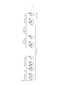
- FIG. 3 is a diagram illustrating an example of a chirp signal generated by the signal generation unit 21.
- the horizontal axis represents the elapsed time and the vertical axis represents the frequency.
- the signal generation unit 21 generates a linear chirp signal whose frequency changes linearly periodically.
- each chirp signal is shown as c1, c2, ..., C8.
- the frequency increases linearly with the passage of time.
- each of the 16 subframes such as the frame 1 and the frame 2 shown in FIG. 3 is included.
- a frame interval having a predetermined length may be included between the frames.
- One frame shown in FIG. 3 may have a length of, for example, about 30 milliseconds to 50 milliseconds.
- the same configuration may be used for the frame 2 and subsequent frames. Further, in FIG. 3, the frame 3 and subsequent frames may have the same configuration.
- the signal generation unit 21 may generate a transmission signal as an arbitrary number of frames. Further, in FIG. 3, some chirp signals are omitted. In this way, the relationship between the time and frequency of the transmission signal generated by the signal generation unit 21 may be stored in, for example, a storage unit 40.
- the electronic device 1 may transmit a transmission signal composed of subframes including a plurality of chirp signals. Further, the electronic device 1 according to the embodiment may transmit a transmission signal composed of frames including a predetermined number of subframes.
- the electronic device 1 will be described as transmitting a transmission signal having a frame structure as shown in FIG.
- the frame structure as shown in FIG. 3 is an example, and for example, the number of chirp signals contained in one subframe is not limited to eight.
- the signal generator 21 may generate subframes containing any number (eg, any number of) chirp signals.
- the subframe structure as shown in FIG. 3 is also an example, and for example, the subframe included in one frame is not limited to 16.
- the signal generator 21 may generate frames that include any number (eg, any number of) subframes.
- the signal generation unit 21 may generate signals having different frequencies.
- the signal generation unit 21 may generate a plurality of discrete signals having different bandwidths with different frequencies f.
- the synthesizer 22 raises the frequency of the signal generated by the signal generation unit 21 to a frequency in a predetermined frequency band.
- the synthesizer 22 may increase the frequency of the signal generated by the signal generation unit 21 to a frequency selected as the frequency of the transmission wave T transmitted from the transmission antenna 25.
- the frequency selected as the frequency of the transmission wave T transmitted from the transmission antenna 25 may be set by, for example, the control unit 10.
- the frequency selected as the frequency of the transmitted wave T transmitted from the transmitting antenna 25 may be the frequency selected by the parameter setting unit 16.
- the frequency selected as the frequency of the transmission wave T transmitted from the transmission antenna 25 may be stored in, for example, the storage unit 40.
- the signal whose frequency has been increased by the synthesizer 22 is supplied to the phase control unit 23 and the mixer 33.
- the signal whose frequency has been increased by the synthesizer 22 may be supplied to each of the plurality of phase control units 23.
- the signal whose frequency has been increased by the synthesizer 22 may be supplied to each mixer 33 in the plurality of receiving units 30.
- the phase control unit 23 controls the phase of the transmission signal supplied from the synthesizer 22. Specifically, the phase control unit 23 may adjust the phase of the transmission signal by appropriately advancing or delaying the phase of the signal supplied from the synthesizer 22 based on, for example, the control by the control unit 10. In this case, the phase control unit 23 may adjust the phase of each transmission signal based on the path difference of each transmission wave T transmitted from the plurality of transmission antennas 25. By appropriately adjusting the phase of each transmission signal by the phase control unit 23, the transmission waves T transmitted from the plurality of transmission antennas 25 strengthen each other in a predetermined direction to form a beam (beamforming).
- the correlation between the beamforming direction and the phase amount to be controlled of the transmission signals transmitted by the plurality of transmission antennas 25 may be stored in the storage unit 40, for example.
- the transmission signal whose phase is controlled by the phase control unit 23 is supplied to the amplifier 24.
- the amplifier 24 amplifies the power of the transmission signal supplied from the phase control unit 23, for example, based on the control by the control unit 10.
- the plurality of amplifiers 24 control the power (power) of the transmission signal supplied from the corresponding one of the plurality of phase control units 23, for example, by the control unit 10.
- Each may be amplified based on the above. Since the technique itself for amplifying the power of the transmission signal is already known, a more detailed description will be omitted.
- the amplifier 24 is connected to the transmitting antenna 25.
- the transmission antenna 25 outputs (transmits) the transmission signal amplified by the amplifier 24 as a transmission wave T.
- the plurality of transmitting antennas 25 may output (transmit) the transmission signals amplified by the corresponding ones of the plurality of amplifiers 24 as transmission waves T, respectively. Since the transmitting antenna 25 can be configured in the same manner as the transmitting antenna used in known radar technology, a more detailed description thereof will be omitted.
- the electronic device 1 is provided with the transmitting antenna 25, and can transmit a transmission signal (for example, a transmission chirp signal) as a transmission wave T from the transmission antenna 25.
- a transmission signal for example, a transmission chirp signal
- at least one of the functional units constituting the electronic device 1 may be housed in one housing.
- the one housing may have a structure that cannot be easily opened.
- the transmitting antenna 25, the receiving antenna 31, and the amplifier 24 are housed in one housing, and the housing cannot be easily opened.
- the transmitting antenna 25 transmits the transmitted wave T to the outside of the moving body 100 via a cover member such as a radar cover. You may.
- the radar cover may be made of a substance that allows electromagnetic waves to pass through, such as synthetic resin or rubber.
- This radar cover may be, for example, a housing of the sensor 5.
- a member such as a radar cover, it is possible to reduce the risk that the transmitting antenna 25 will be damaged or malfunction due to contact with the outside.
- the radar cover and housing may also be referred to as a radome.
- the electronic device 1 shown in FIG. 2 shows an example in which two transmitting antennas 25 are provided. However, in one embodiment, the electronic device 1 may include any number of transmitting antennas 25. On the other hand, in one embodiment, the electronic device 1 may include a plurality of transmitting antennas 25 when the transmitted wave T transmitted from the transmitting antenna 25 forms a beam in a predetermined direction. In one embodiment, the electronic device 1 may include any plurality of transmitting antennas 25. In this case, the electronic device 1 may be provided with a plurality of phase control units 23 and a plurality of amplifiers 24 in correspondence with the plurality of transmitting antennas 25.
- the plurality of phase control units 23 may control the phases of the plurality of transmitted waves supplied from the synthesizer 22 and transmitted from the plurality of transmitting antennas 25, respectively.
- the plurality of amplifiers 24 may amplify the power of the plurality of transmission signals transmitted from the plurality of transmission antennas 25, respectively.
- the sensor 5 may be configured to include a plurality of transmitting antennas. As described above, when the electronic device 1 shown in FIG. 2 is provided with a plurality of transmitting antennas 25, the electronic device 1 is configured to include a plurality of functional units necessary for transmitting the transmitted wave T from the plurality of transmitting antennas 25. Good.
- the receiving antenna 31 receives the reflected wave R.
- the reflected wave R is a transmitted wave T reflected by a predetermined object 200.
- the receiving antenna 31 may include a plurality of antennas, such as the receiving antenna 31A to the receiving antenna 31D. Since the receiving antenna 31 can be configured in the same manner as the receiving antenna used in the known radar technology, a more detailed description thereof will be omitted.
- the receiving antenna 31 is connected to the LNA 32.
- the received signal based on the reflected wave R received by the receiving antenna 31 is supplied to the LNA 32.
- the electronic device 1 has a reflected wave R in which a transmitted wave T transmitted as a transmission signal (transmission chirp signal) such as a chirp signal is reflected by a predetermined object 200 from a plurality of receiving antennas 31. Can be received.
- a transmission signal transmission chirp signal
- the reception signal based on the received reflected wave R is referred to as a reception chirp signal. That is, the electronic device 1 receives the received signal (for example, the received chirp signal) as the reflected wave R from the receiving antenna 31.
- the receiving antenna 31 may receive the reflected wave R from the outside of the moving body 100 via a cover member such as a radar cover.
- the radar cover may be made of a substance that allows electromagnetic waves to pass through, such as synthetic resin or rubber.
- This radar cover may be, for example, a housing of the sensor 5.
- one sensor 5 may include, for example, at least one transmitting antenna 25 and at least one receiving antenna 31.
- one sensor 5 may include a plurality of transmitting antennas 25 and a plurality of receiving antennas 31.
- one radar sensor may be covered with a cover member such as one radar cover.
- the LNA 32 amplifies the received signal based on the reflected wave R received by the receiving antenna 31 with low noise.
- the LNA 32 may be used as a low noise amplifier, and amplifies the received signal supplied from the receiving antenna 31 with low noise.
- the received signal amplified by the LNA 32 is supplied to the mixer 33.
- the mixer 33 generates a beat signal by mixing (multiplying) the received signal of the RF frequency supplied from the LNA 32 with the transmission signal supplied from the synthesizer 22.
- the beat signal mixed by the mixer 33 is supplied to the IF unit 34.
- the IF unit 34 reduces the frequency of the beat signal to an intermediate frequency (IF (Intermediate Frequency) frequency) by performing frequency conversion to the beat signal supplied from the mixer 33.
- IF Intermediate Frequency
- the AD conversion unit 35 digitizes the analog beat signal supplied from the IF unit 34.
- the AD conversion unit 35 may be configured by any analog-to-digital conversion circuit (Analog to Digital Converter (ADC)).
- ADC Analog to Digital Converter
- the beat signal digitized by the AD conversion unit 35 is supplied to the distance FFT processing unit 11 of the control unit 10.
- each beat signal digitized by the plurality of AD conversion units 35 may be supplied to the distance FFT processing unit 11.
- the distance FFT processing unit 11 estimates the distance between the moving body 100 equipped with the electronic device 1 and the object 200 based on the beat signal supplied from the AD conversion unit 35.
- the distance FFT processing unit 11 may include, for example, a processing unit that performs a fast Fourier transform.
- the distance FFT processing unit 11 may be composed of an arbitrary circuit or chip that performs a fast Fourier transform (FFT) process.
- the distance FFT processing unit 11 performs FFT processing on the beat signal digitized by the AD conversion unit 35 (hereinafter, appropriately referred to as "distance FFT processing").
- the distance FFT processing unit 11 may perform FFT processing on the complex signal supplied from the AD conversion unit 35.
- the beat signal digitized by the AD conversion unit 35 can be represented as a time change in signal strength (electric power).
- the distance FFT processing unit 11 can express the signal strength (power) corresponding to each frequency by performing FFT processing on such a beat signal.
- the distance FFT processing unit 11 may determine that the predetermined object 200 is at a distance corresponding to the peak.
- CFAR Constant False Alarm Rate
- the electronic device 1 targets the object 200 that reflects the transmitted wave T based on the transmitted signal transmitted as the transmitted wave T and the received signal received as the reflected wave R. Can be detected.
- Distance FFT processing unit 11 can estimate the distance to a predetermined object based on one chirp signal (for example, c1 shown in FIG. 3). That is, the electronic device 1 can measure (estimate) the distance L shown in FIG. 1 by performing the distance FFT process. Since the technique itself for measuring (estimating) the distance to a predetermined object by performing FFT processing on the beat signal is known, a more detailed description will be simplified or omitted as appropriate.
- the result of the distance FFT processing performed by the distance FFT processing unit 11 (for example, distance information) may be supplied to the speed FFT processing unit 12. Further, the result of the distance FFT processing performed by the distance FFT processing unit 11 may be supplied to the distance velocity detection determination unit 13 and / or the object detection unit 15.
- the velocity FFT processing unit 12 estimates the relative velocity between the moving body 100 equipped with the electronic device 1 and the object 200 based on the beat signal subjected to the distance FFT processing by the distance FFT processing unit 11.
- the speed FFT processing unit 12 may include, for example, a processing unit that performs a fast Fourier transform.
- the speed FFT processing unit 12 may be composed of an arbitrary circuit or chip that performs a fast Fourier transform (FFT) process.
- FFT fast Fourier transform
- the speed FFT processing unit 12 further performs FFT processing on the beat signal subjected to the distance FFT processing by the distance FFT processing unit 11 (hereinafter, appropriately referred to as "speed FFT processing").
- the velocity FFT processing unit 12 may perform FFT processing on the complex signal supplied from the distance FFT processing unit 11.
- the velocity FFT processing unit 12 can estimate the relative velocity with a predetermined object based on the subframe of the chirp signal (for example, the subframe 1 shown in FIG. 3).
- a plurality of vectors can be generated.
- the relative velocity with a predetermined object can be estimated by obtaining the phase of the peak in the result of performing the velocity FFT processing on these plurality of vectors.
- the electronic device 1 can measure (estimate) the relative velocity between the moving body 100 shown in FIG. 1 and the predetermined object 200 by performing the velocity FFT process. Since the technique itself for measuring (estimating) the relative velocity with a predetermined object by performing the velocity FFT process on the result of performing the distance FFT process is known, a more detailed description may be simplified or omitted as appropriate. To do.
- the result of the velocity FFT processing performed by the velocity FFT processing unit 12 (for example, velocity information) may be supplied to the arrival angle estimation unit 14. Further, the result of the velocity FFT processing performed by the velocity FFT processing unit 12 may be supplied to the distance velocity detection determination unit 13 and / or the object detection unit 15.
- the distance speed detection determination unit 13 is based on the result of the distance FFT processing performed by the distance FFT processing unit 11 and / or the result of the speed FFT processing performed by the speed FFT processing unit 12, and / or relative. Judgment processing for speed is performed.
- the distance speed detection determination unit 13 determines whether or not the target has been detected at a predetermined distance and / or a predetermined relative velocity. The distance / velocity detection / determination unit 13 will be described later.
- the arrival angle estimation unit 14 estimates the direction in which the reflected wave R arrives from the predetermined object 200 based on the result of the velocity FFT processing performed by the velocity FFT processing unit 12.
- the electronic device 1 can estimate the direction in which the reflected wave R arrives by receiving the reflected wave R from the plurality of receiving antennas 31.
- the plurality of receiving antennas 31 are arranged at predetermined intervals. In this case, the transmitted wave T transmitted from the transmitting antenna 25 is reflected by the predetermined object 200 to become the reflected wave R, and the plurality of receiving antennas 31 arranged at predetermined intervals each receive the reflected wave R.
- the arrival angle estimation unit 14 estimates the direction in which the reflected wave R arrives at the receiving antenna 31 based on the phase of the reflected wave R received by the plurality of receiving antennas 31 and the path difference of each reflected wave R. can do. That is, the electronic device 1 can measure (estimate) the arrival angle ⁇ shown in FIG. 1 based on the result of performing the speed FFT process.
- MUSIC MUltiple SIgnal Classification
- ESPRIT Estimat of Signal Parameters via Rotational Invariance Technique
- the object detection unit 15 detects an object existing in the range in which the transmission wave T is transmitted, based on information supplied from at least one of the distance FFT processing unit 11, the velocity FFT processing unit 12, and the arrival angle estimation unit 14. To detect.
- the object detection unit 15 may perform object detection by performing clustering processing, for example, based on the supplied distance information, velocity information, and angle information.
- clustering processing for example, based on the supplied distance information, velocity information, and angle information.
- DBSCAN Density-based spatial clustering of applications with noise
- the average power of the points constituting the detected object may be calculated.
- the distance information, velocity information, angle information, and electric power information of the object detected by the object detection unit 15 may be supplied to the detection range determination unit 15.
- the distance information, the velocity information, the angle information, and the electric power information of the object detected by the object detection unit 15 may be supplied to the ECU 50.
- communication may be performed using a communication interface such as CAN (Controller Area Network).
- the ECU 50 included in the electronic device 1 can control the operation of the entire mobile body 100, including the control of each functional unit constituting the mobile body 100.
- the ECU 50 may include at least one processor, such as a CPU (Central Processing Unit), in order to provide control and processing power to perform various functions.
- the ECU 50 may be realized collectively by one processor, by several processors, or by individual processors.
- the processor may be implemented as a single integrated circuit.
- the integrated circuit is also called an IC (Integrated Circuit).
- the processor may be implemented as a plurality of communicably connected integrated circuits and discrete circuits.
- the processor may be implemented on the basis of various other known techniques.
- the ECU 50 may be configured as, for example, a CPU and a program executed by the CPU.
- the ECU 50 may appropriately include a memory required for the operation of the ECU 50. Further, at least a part of the function of the control unit 10 may be a function of the ECU 50, or at least a part of the function of the ECU 50 may be a function of the control unit 10.
- the electronic device 1 shown in FIG. 2 includes two transmitting antennas 25 and four receiving antennas 31.
- the electronic device 1 according to the embodiment may include an arbitrary number of transmitting antennas 25 and an arbitrary number of receiving antennas 31.
- the electronic device 1 can be considered to include a virtual antenna array virtually composed of eight antennas.
- the electronic device 1 may receive the reflected wave R of the 16 subframes shown in FIG. 3 by using, for example, eight virtual antennas.
- the electronic device 1 transmits the transmitted wave from the transmitting antenna, and receives the reflected wave reflected by the target object and / or the clutter from the receiving antenna. Then, the electronic device 1 according to the embodiment can detect an object that reflects the transmitted wave as a target based on the transmitted signal and / or the received signal.
- the result of extracting the beat frequency from the received signal and performing the fast Fourier transform process includes a noise component due to a clutter (unnecessary reflection component) or the like. Therefore, a process for removing the noise component from the result of processing the received signal and extracting only the target signal may be executed.
- a method of determining whether or not a target exists there is a method of setting a threshold value for the output of the received signal and assuming that the target exists when the intensity of the reflected signal exceeds the threshold value (threshold detection method).
- threshold detection method When this method is adopted, even if the signal strength of the clutter exceeds the threshold value, it is determined as a target, and a so-called “false alarm” is issued. Whether or not the signal strength of this clutter exceeds the threshold value is probabilistic. The probability that the signal strength of this clutter exceeds the threshold is called the "false alarm probability".
- a constant false alarm probability Constant False Alarm Rate
- the constant false alarm probability (Constant False Alarm Rate) is also simply referred to as CFAR.
- CFAR the assumption is used that the signal strength (amplitude) of noise follows a Rayleigh distribution. Based on this assumption, if the weight for calculating the threshold used to determine whether or not the target is detected is fixed, the error rate of target detection is theoretically constant regardless of the amplitude of noise. ..
- CA-CFAR Cell Averaging CFAR
- the signal strength value for example, the amplitude value
- the signal strength value of the received signal subjected to the predetermined processing may be sequentially input to the shift register at regular sampling cycles.
- This shift register has an inspection cell (cell under test) in the center, and has a plurality of reference cells on both sides of the inspection cell. Each time a signal strength value is entered into the shift register, one previously entered signal strength value is placed in the cell from one end side (eg left end side) to the other end side (eg right end side) of the shift register. Moved one by one.
- each value of the reference cell is averaged in synchronization with the input timing.
- the average value obtained in this way is multiplied by a predetermined weight and calculated as a threshold value.
- the value of the inspection cell is output as it is.
- a 0 (zero) value is output.
- the detection result can be obtained by calculating the threshold value from the average value of the reference cells and determining whether or not the target exists.
- CA-CFAR for example, when a plurality of targets exist in close proximity to each other, the threshold value calculated in the vicinity of the targets becomes large due to the nature of the algorithm. Therefore, some targets may not be detected even though they have sufficient signal strength. Similarly, when there is a step in the clutter, the calculated threshold value becomes large even in the vicinity of the step in the clutter. Again, small targets near the clutter steps may not be detected.
- OrderStatistic CFAR (hereinafter, hereinafter There is a method called OS-CFAR).
- OS-CFAR is a method of setting a threshold value based on ordered statistics and determining that a target exists when the threshold value is exceeded. According to this OS-CFAR, the above-mentioned problems in CA-CFAR can be dealt with.
- OS-CFAR can be realized by performing a process that is partially different from CA-CFAR.
- the electronic device 1 according to the embodiment may perform OS-CFAR processing in, for example, the distance speed detection determination unit 13 of the control unit 10 shown in FIG.
- the electronic device 1 according to the embodiment may perform OS-CFAR processing in, for example, the distance FFT processing unit 11 and / or the speed FFT processing unit 12 of the control unit 10 shown in FIG.
- OS-CFAR processing in, for example, the distance FFT processing unit 11 and / or the speed FFT processing unit 12 of the control unit 10 shown in FIG.
- the frequency of the chirp signal generated by the signal generation unit 21 is increased to the frequency of the frequency band selected by the synthesizer 22.
- the chirp signal whose frequency has been increased is transmitted from the transmitting antenna 25 via the phase control unit 23, the amplifier 24, and the like.
- the chirp signal reflected by the reflecting object is received by the AD conversion unit 35 via the IF unit 34 after being multiplied by the transmission signal in the mixer 33 after passing through the receiving antenna 31 and the LNA 32.
- the complex signal received by the AD conversion unit 35 is subjected to distance FFT processing by the distance FFT processing unit 11.
- the distance velocity detection determination unit 13 may execute the OS-CFAR process on the signal to which the distance FFT process has been performed.
- FIG. 4 is a block diagram illustrating a process in the control unit 10 of the electronic device 1 according to the embodiment. More specifically, FIG. 4 is a diagram illustrating an example of the logic of the circuit that executes the OS-CFAR process in the distance speed detection determination unit 13 of the control unit 10.
- the distance speed detection determination unit 13 has a shift register 131, a sort unit 132, a data selection unit 133, a threshold value calculation unit 134, a weight setting unit 135, and a detection unit 13, as shown in FIG.
- the determination unit 136 may be included.
- the value of the signal strength of the received signal subjected to the predetermined processing may be sequentially input to the shift register 131 at regular sampling cycles. Each time a signal strength value is entered into the shift register 131, the previously entered signal strength value is moved from one end side (eg left end side) to the other end side (eg right end side) cell of the shift register 131. It may be moved one by one. As described above, in one embodiment, the shift register 131 (of the distance / velocity detection determination unit 13) shifts the signal strength based on the received signal input from one in a predetermined sampling cycle toward the other by the first-in first-out method. You can.
- the shift register 131 may have an inspection cell T in the central inspection area.
- the area where the inspection cell T is arranged is also referred to as an “inspection area”.
- the shift register 131 may have guard cells G in guard regions on both sides of the inspection cell T, respectively.
- the guard cells G are shown as two consecutive cells, but the number of guard cells G may be arbitrary.
- the area where the guard cell G is arranged is also referred to as a “guard area”.
- the shift register 131 has a plurality of reference cells R in the reference area outside each guard cell G. In FIG. 4, the reference cells R are shown as four consecutive cells, but the number of reference cells R may be arbitrary.
- the control unit 10 may provide a guard area between the inspection area and the reference area in the distance direction.
- the shift register 131 may include an inspection cell T in the inspection area and a reference cell R in the reference area.
- the sort unit 132 sorts the values output from each of the reference cells R in ascending order.
- the sort unit 132 may be configured by, for example, an arbitrary sort circuit.
- the sort unit 132 may sort the values of the reference cells R in ascending order in synchronization with the timing at which the signal strength is input to the shift register 131.
- the control unit 10 distance speed detection determination unit 13
- the data selection unit 133 may select and extract the value at the specified position (for example, the predetermined number from the smallest) among the values sorted by the sort unit 132.
- the control unit 10 includes a data selection unit 133 that selects a predetermined signal strength among the signal strengths sorted by the sort unit 132. May be good.
- the threshold value calculation unit 134 may calculate the threshold value Th by multiplying the value selected by the data selection unit 133 by a predetermined weight.
- the weight setting unit 135 may calculate the threshold value Th by multiplying the value selected by the data selection unit 133, for example, the specified weight M.
- the control unit 10 sets the threshold value calculation unit 134 that sets the threshold value used for target detection based on the signal strength selected by the data selection unit 133. You may prepare.
- the detection determination unit 136 compares the magnitude of the signal strength value A in the test cell T with the threshold value Th calculated by the threshold value calculation unit 134. When the signal intensity value A in the test cell T is larger than the threshold value Th, the detection determination unit 136 outputs the signal intensity value A in the test cell T as it is as a detection result. On the other hand, when the value A of the signal strength in the test cell T is not larger than the threshold value Th, the detection determination unit 136 outputs zero as the detection result. As described above, in one embodiment, the control unit 10 (detection determination unit 136 of the distance / velocity detection determination unit 13) determines the presence / absence of the target based on the signal strength A and the threshold value Th of the inspection cell T in the inspection region. You can do it.
- the threshold value can be calculated from the value of the specified position (for example, the predetermined order from the smallest order) among the sorted signal intensities, and the influence of the signal based on the reflected wave on the calculation of the threshold value can be suppressed. Therefore, in OS-CFAR, the rise of the threshold value can be suppressed in the vicinity of the target. Further, in OS-CFAR, an increase in the threshold value can be suppressed in the vicinity of the step of the clutter.
- the beat signal digitized by the AD conversion unit 35 is subjected to the distance FFT processing by the distance FFT processing unit 11, so that the distribution of the signal strength (electric power) in the distance direction can be obtained.
- the right side of the shift register 131 may correspond to a distance far from the sensor 5 of the electronic device 1.
- the left side of the shift register 131 may correspond to a distance close to the sensor 5 of the electronic device 1.
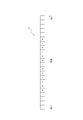
- FIG. 5 is a diagram illustrating an example of executing the OS-CFER process in the electronic device 1 according to the embodiment.
- the inspection cell T, the guard cell G, and the reference cell R are arranged in the same manner as in the example shown in FIG.
- the electronic device 1 according to the embodiment can determine the distance detection. That is, the control unit 10 of the electronic device 1 according to the embodiment calculates the distance threshold value Th based on the value of the predetermined signal strength (electric power) in the reference cell R from the lowest (for example, the Kth). Then, the control unit 10 of the electronic device 1 according to the embodiment can determine that the target exists in the inspection region if the value A of the signal strength in the inspection cell T is larger than the distance threshold Th.
- the speed FFT processing unit 12 of the control unit 10 may perform speed FFT processing on a plurality of chirp signals. Further, the speed FFT processing unit 12 may determine the speed detection in the same manner as the distance FFT processing unit 11 described above.
- the lower side of the shift register 131 may correspond to a region where the relative speed between the sensor 5 of the electronic device 1 and the target is high.
- the upper side of the shift register 131 may correspond to a region where the relative speed between the sensor 5 of the electronic device 1 and the target is slow.
- FIG. 6 is a diagram illustrating an example of executing the OS-CFER process in the electronic device 1 according to the embodiment.
- the inspection cell T, the guard cell G, and the reference cell R are arranged, but the arrangement shown in FIG. 6 is an example.
- the electronic device 1 according to the embodiment can determine the speed detection based on the constant false alarm probability in the speed direction.
- a plurality of reference cells R are continuously arranged on both sides of the inspection area in the distance direction.
- the reference cell R is arranged as in the shift register 131 shown in FIG. 5, it is assumed that the target is not detected correctly depending on the situation.
- the in-vehicle radar is used to detect other vehicles and the like existing around the own vehicle.
- an object such as an iron fence is installed without interruption over a long distance in parallel with the lane in which the own vehicle travels.
- the distance between an object such as an iron fence installed in parallel with the lane and the own vehicle is maintained substantially constant during traveling.
- the in-vehicle radar can detect the iron fence as a target.
- other vehicles for example, are running in parallel in the lane parallel to the iron fence.
- the reference area in which the reference cell R is arranged becomes an area corresponding to the signal strength due to the reflected wave reflected by the iron fence.
- the signal strength value A in the inspection cell T in the inspection region does not exceed the threshold Th due to the increase in noise power. Therefore, it is assumed that the in-vehicle radar cannot detect the vehicle as a target.
- the signal strength (electric power) based on the reflected wave tends to increase as the distance from the radar increases. Therefore, when referring to the front side of the target, the value A of the signal strength in the inspection cell T in the inspection region does not exceed the threshold Th due to the increase in noise power. Even in such a case, it is assumed that the in-vehicle radar cannot detect the target as a target.
- the electronic device 1 according to the embodiment arranges the reference area (reference cell R) two-dimensionally in the shift register 131. Further, the electronic device 1 according to the embodiment changes the arrangement of the reference area (reference cell R) in the shift register 131 configured two-dimensionally.
- the electronic device 1 according to the embodiment will be described as detecting the target with a constant false alarm probability.
- FIG. 7 is a diagram showing an example of a two-dimensional arrangement of a reference region (reference cell R) in the shift register 131 of the electronic device 1 according to the embodiment.
- the inspection cell T, the guard cell G, and the reference cell R are arranged, but the arrangement shown in FIG. 7 is an example.
- the right side of the shift register 131 corresponds to a distance far from the sensor 5 of the electronic device 1
- the left side of the shift register 131 corresponds to a distance close to the sensor 5 of the electronic device 1.
- FIG. 7 similarly to FIG.
- the lower side of the shift register 131 corresponds to the region where the relative speed with respect to the sensor 5 of the electronic device 1 is high, and the upper side of the shift register 131 corresponds to the sensor 5 of the electronic device 1. Corresponds to the region where the relative speed is slow.
- the shift register 131 of the distance velocity detection determination unit 13 shown in FIG. 4 has a reference area (reference cell R) arranged one-dimensionally only in the distance direction.
- the shift register 131 of the distance / velocity detection determination unit 13 may arrange the reference region (reference cell R) two-dimensionally in the distance direction and the velocity direction.
- the control unit 10 includes the inspection cell T in the inspection area and the reference cell R in the reference area in the distance direction and the relative speed direction.
- the two-dimensional shift register 131 of the above may be provided.
- the distance FFT process 11 may perform a distance Fourier transform on a plurality of chirp signals. Further, the speed FFT processing unit 12 may further perform a speed Fourier transform on the signal subjected to the distance Fourier transform by the distance FFT processing 11. Therefore, the distance / velocity detection / determination unit 13 may simultaneously perform the detection / determination of the distance and the velocity with respect to the result of further performing the velocity Fourier transform on the signal obtained by the distance Fourier transform on the plurality of chirp signals.
- the shift register 131 of the electronic device 1 according to the embodiment arranges the reference area (reference cell R) farther in the distance direction from the inspection area (inspection cell T). That is, the shift register 131 of the electronic device 1 according to the embodiment does not have to arrange the reference area closer to the inspection area in the distance direction.
- the reference area is not arranged in the area corresponding to the short distance, and the reference area is arranged in the area corresponding to the long distance.
- the shift register 131 of the electronic device 1 according to the embodiment may intermittently arrange the reference area (reference cell R) in the distance direction. That is, the shift register 131 of the electronic device 1 according to the embodiment may be arranged so that the reference cells R are not continuous in the distance direction.
- the reference cells R are arranged intermittently without being continuous in the distance direction.
- eight reference cells R are intermittently arranged in the distance direction.
- the number of reference cells R to be arranged may be arbitrary depending on, for example, the mode of target detection or the required accuracy. Further, in the example shown in FIG. 7, the reference cells R are arranged every other in the distance direction.
- the interval at which the reference cell R is intermittently arranged in the distance direction may be arbitrary depending on, for example, the mode of target detection or the required accuracy. Further, the arrangement interval of each reference cell R may be an arbitrary interval, and the arrangement interval of each reference cell R may be an equal interval, or may be a different interval for each.
- the shift register 131 of the electronic device 1 according to the embodiment may intermittently arrange the reference area (reference cell R) also in the speed direction. That is, the shift register 131 of the electronic device 1 according to the embodiment may be arranged so that the reference cells R are not continuous in the speed direction.
- the reference cells R are arranged intermittently without being continuous in the speed direction.
- eight reference cells R are intermittently arranged in the speed direction.
- the number of reference cells R to be arranged may be arbitrary depending on, for example, the mode of target detection or the required accuracy.
- the reference cells R are arranged every other in the speed direction.
- the interval at which the reference cell R is intermittently arranged in the velocity direction may be arbitrary depending on, for example, the mode of target detection or the required accuracy.
- the shift register 131 may have guard cells G in the guard regions on both sides of the inspection cell T in the distance direction, as in the case of FIG. Further, the shift register 131 may have guard cells G in the guard regions on both sides of the inspection cell T even in the speed direction.
- the control unit 10 may provide a guard area (guard cell G) around the inspection area (inspection cell T). Further, in one embodiment, the control unit 10 (shift register 131 of the distance speed detection determination unit 13) is placed in a guard area (guard cell) around the inspection area (inspection cell T) and adjacent to the inspection area (inspection cell T). G) may be provided.
- guard cell G guard area around the inspection area (inspection cell T) and adjacent to the inspection area (inspection cell T).
- the guard cells G are shown as two consecutive cells in both the distance direction and the speed direction, but the number of guard cells G may be arbitrary.
- the guard cells G may have different numbers of cells in the distance direction and the speed direction.
- the guard cells G may have different numbers of cells on both sides of the inspection cell T in at least one of the distance direction and the speed direction.
- the electronic device 1 according to the embodiment can determine the speed detection by the OS-CFAR described above. That is, the control unit 10 of the electronic device 1 according to the embodiment calculates the speed threshold value Th based on the value of the predetermined signal strength (electric power) in the reference cell R from the lowest (for example, the Kth). Then, the control unit 10 of the electronic device 1 according to the embodiment can determine that the target exists in the inspection region if the value A of the signal strength in the inspection cell T is larger than the speed threshold Th.
- the electronic device 1 can determine the detection of the distance and the speed with a constant false alarm probability.
- the arrival angle estimation unit 14 estimates the arrival direction of the reflected wave based on the complex signals received by the plurality of receiving antennas 31 at the speed at which the target is determined to exist. You may. In this way, the electronic device 1 according to the embodiment can estimate the angle in the direction in which the target exists.
- the object detection unit 15 is an object based on information on the arrival direction (angle) of the reflected wave, information on the relative velocity with the target, and / or information on the distance to the target. Is detected (for example, clustering) or not as a target.
- the information on the arrival direction (angle) of the reflected wave may be acquired from the arrival angle estimation unit 14.
- the information on the relative speed and the distance to the target may be acquired from the distance speed detection determination unit 13.
- the information on the relative speed with the target may be acquired from the speed FFT processing unit 12.
- the information on the distance to the target may be acquired from the distance FFT processing unit 11.
- the object detection unit 15 may calculate the average power of the points constituting the object to be detected as the target.
- the control unit 10 detects the target with a constant false alarm probability based on the transmission signal transmitted as the transmission wave and the reception signal received as the reflected wave.
- the control unit 10 intermittently refers to the far side in the distance direction and the relative speed direction with reference to the inspection region in the two-dimensional distribution of the signal strength based on the received signal in the distance direction and the relative speed direction.
- a region reference cell R
- the control unit 10 sets the reference region in the two-dimensional distribution in the distance direction and the relative velocity direction of the signal strength based on the received signal obtained by performing at least one of the distance Fourier transform processing and the velocity Fourier transform processing. It may be provided intermittently.
- control unit 10 sets the threshold value Th used for detecting the target based on the order statistic of the signal strength in the reference region (reference cell R).
- reference cell R the control unit 10 refers to the relative velocity direction and at least the far and near distance directions with reference to the inspection area. One of them may be used to intermittently provide a reference region (reference cell R).
- the noise reference region (reference cell R) is arranged so as to be far from the inspection region (T) of the target object in the distance direction. Further, in one embodiment, the reference area (reference cell R) is arranged intermittently in the distance direction. Further, in one embodiment, the reference region (reference cell R) is arranged intermittently in the velocity direction as well. That is, the electronic device 1 according to the embodiment performs distance FFT processing on a plurality of chirp signals and then intermittently refers to the result of performing speed FFT processing on the far side in the distance direction and in the speed direction ( The reference cell R) is arranged.
- the electronic device 1 according to the embodiment receives a reflected wave due to a relatively large (long) interfering object that maintains a constant interval while traveling, for example, with its own vehicle equipped with an in-vehicle radar.
- Noise power can be detected so as to remove interfering substances.
- an object to be detected can be detected even if the relative speed with the own vehicle or the like is a predetermined speed and there is interference by a large (long) object in the distance direction. Therefore, according to the electronic device 1 according to the embodiment, the accuracy of detecting the target can be improved.
- the electronic device 1 according to the embodiment has a relative speed. Detects noise in different regions. Therefore, the electronic device 1 according to the embodiment can detect even another vehicle traveling in a lane parallel to the above-mentioned iron fence, for example. Therefore, according to the electronic device 1 according to the embodiment, the accuracy of detecting the target can be improved.
- each functional unit, each means, each step, etc. are added to other embodiments so as not to be logically inconsistent, or each functional unit, each means, each step, etc. of other embodiments. Can be replaced with. Further, in each embodiment, it is possible to combine or divide a plurality of each functional unit, each means, each step, and the like into one. Further, each of the above-described embodiments of the present disclosure is not limited to faithful implementation of each of the embodiments described above, and each feature may be combined or a part thereof may be omitted as appropriate. You can also do it.
- the object may be detected in the object detection range determined by the plurality of sensors 5.
- beamforming may be performed toward a determined object detection range by a plurality of sensors 5.
- the above-described embodiment is not limited to the implementation as the electronic device 1.
- the above-described embodiment may be implemented as a control method for a device such as the electronic device 1.
- the above-described embodiment may be implemented as a program executed by a device such as the electronic device 1.
- the electronic device 1 according to the embodiment may include at least a part of only one of the sensor 5 and the control unit 10, for example, as the minimum configuration.
- the electronic device 1 according to the embodiment is at least one of a signal generation unit 21, a synthesizer 22, a phase control unit 23, an amplifier 24, and a transmission antenna 25, as shown in FIG. 2, in addition to the control unit 10. May be included as appropriate.
- the electronic device 1 according to the embodiment has at least one of the receiving antenna 31, LNA 32, mixer 33, IF unit 34, and AD conversion unit 35 in place of or together with the above-mentioned functional unit. It may be included as appropriate.
- the electronic device 1 according to the embodiment may include a storage unit 40.
- the electronic device 1 according to the embodiment can adopt various configuration modes. Further, when the electronic device 1 according to the embodiment is mounted on the mobile body 100, for example, at least one of the above-mentioned functional units may be installed in an appropriate place such as inside the mobile body 100. On the other hand, in one embodiment, for example, at least one of the transmitting antenna 25 and the receiving antenna 31 may be installed outside the mobile body 100.
Landscapes
- Engineering & Computer Science (AREA)
- Radar, Positioning & Navigation (AREA)
- Remote Sensing (AREA)
- Physics & Mathematics (AREA)
- Computer Networks & Wireless Communication (AREA)
- General Physics & Mathematics (AREA)
- Electromagnetism (AREA)
- Radar Systems Or Details Thereof (AREA)
Priority Applications (4)
| Application Number | Priority Date | Filing Date | Title |
|---|---|---|---|
| US17/595,135 US12196846B2 (en) | 2019-05-29 | 2020-05-12 | Electronic device, method for controlling electronic device, and program |
| EP20813383.5A EP3978946A4 (en) | 2019-05-29 | 2020-05-12 | Electronic apparatus, method for controlling electronic apparatus, and program |
| JP2021522176A JP7550751B2 (ja) | 2019-05-29 | 2020-05-12 | 電子機器、電子機器の制御方法、及びプログラム |
| CN202080033845.4A CN113795767A (zh) | 2019-05-29 | 2020-05-12 | 电子设备、电子设备的控制方法以及程序 |
Applications Claiming Priority (2)
| Application Number | Priority Date | Filing Date | Title |
|---|---|---|---|
| JP2019100700 | 2019-05-29 | ||
| JP2019-100700 | 2019-05-29 |
Publications (1)
| Publication Number | Publication Date |
|---|---|
| WO2020241234A1 true WO2020241234A1 (ja) | 2020-12-03 |
Family
ID=73552959
Family Applications (1)
| Application Number | Title | Priority Date | Filing Date |
|---|---|---|---|
| PCT/JP2020/018946 Ceased WO2020241234A1 (ja) | 2019-05-29 | 2020-05-12 | 電子機器、電子機器の制御方法、及びプログラム |
Country Status (5)
| Country | Link |
|---|---|
| US (1) | US12196846B2 (https=) |
| EP (1) | EP3978946A4 (https=) |
| JP (1) | JP7550751B2 (https=) |
| CN (1) | CN113795767A (https=) |
| WO (1) | WO2020241234A1 (https=) |
Families Citing this family (1)
| Publication number | Priority date | Publication date | Assignee | Title |
|---|---|---|---|---|
| WO2019187056A1 (ja) * | 2018-03-30 | 2019-10-03 | アルウェットテクノロジー株式会社 | 速度計測装置、速度計測プログラム、記録媒体および速度計測方法 |
Citations (6)
| Publication number | Priority date | Publication date | Assignee | Title |
|---|---|---|---|---|
| JPH0449886U (https=) * | 1990-08-31 | 1992-04-27 | ||
| JPH11133144A (ja) | 1997-10-30 | 1999-05-21 | Mitsubishi Electric Corp | Fm−cwレーダ装置 |
| JP2006305337A (ja) * | 2005-03-31 | 2006-11-09 | Toshiba Corp | 超音波診断装置及び超音波画像処理方法 |
| US20070211916A1 (en) * | 2004-03-27 | 2007-09-13 | Smith Iain B | Method Of Detecting A Target With A Cfar Thresholding Function Using Clutter Map Entries |
| US20100073218A1 (en) * | 2008-09-24 | 2010-03-25 | Lockheed Martin Corpration | Method and apparatus for radar surveillance and detection of sea targets |
| US20160334512A1 (en) * | 2015-05-14 | 2016-11-17 | Stmicroelectronics S.R.L. | Accelerator engine, corresponding apparatus and method, for instance for anti-collision systems for motor vehicles |
Family Cites Families (26)
| Publication number | Priority date | Publication date | Assignee | Title |
|---|---|---|---|---|
| JP2750191B2 (ja) * | 1990-02-27 | 1998-05-13 | 富士通株式会社 | レーダ信号処理方式 |
| JP4670446B2 (ja) | 2005-04-13 | 2011-04-13 | 日本電気株式会社 | レーダ信号処理装置及びそれに用いるcfar処理方法 |
| US8665113B2 (en) * | 2005-10-31 | 2014-03-04 | Wavetronix Llc | Detecting roadway targets across beams including filtering computed positions |
| US7982671B2 (en) * | 2008-04-17 | 2011-07-19 | Broadcom Corporation | Method and system for using a wireless local area network (WLAN) phase shifter for smart antenna beam steering |
| US20140310594A1 (en) * | 2013-04-15 | 2014-10-16 | Flextronics Ap, Llc | Configuration of haptic feedback and visual preferences in vehicle user interfaces |
| KR20140010311A (ko) * | 2012-07-16 | 2014-01-24 | 경상대학교산학협력단 | 병렬처리를 이용한 레이더 시뮬레이터 장치 및 그 시뮬레이션 방법 |
| JP6192910B2 (ja) * | 2012-09-04 | 2017-09-06 | 富士通テン株式会社 | レーダ装置および物標高算出方法 |
| JP6200644B2 (ja) * | 2012-12-07 | 2017-09-20 | 富士通テン株式会社 | レーダ装置、及び、信号処理方法 |
| DE102012024999A1 (de) * | 2012-12-19 | 2014-06-26 | Valeo Schalter Und Sensoren Gmbh | Verfahren zum Einstellen einer Detektionsschwelle für ein Empfangssignal eines Frequenzmodulations-Dauerstrich-Radarsensors eines Kraftfahrzeugs abhängig vom Rauschpegel, Radarsensor und Kraftfahrzeug |
| KR102204839B1 (ko) * | 2014-02-11 | 2021-01-19 | 한국전자통신연구원 | 레이더를 이용한 표적 검출 장치 및 표적을 검출하는 방법 |
| JP2015172491A (ja) * | 2014-03-11 | 2015-10-01 | 富士通テン株式会社 | アンテナ、レーダ装置、および、車両制御システム |
| JP6384018B2 (ja) * | 2014-03-25 | 2018-09-05 | 日本無線株式会社 | 車載用レーダ装置 |
| KR20150117115A (ko) * | 2014-04-09 | 2015-10-19 | 한국전자통신연구원 | 신호 탐지 시스템에서의 고정 오경보 확률 장치 |
| US9746549B1 (en) * | 2014-07-11 | 2017-08-29 | Altera Corporation | Constant false alarm rate circuitry in adaptive target detection of radar systems |
| EP3173812B1 (en) * | 2015-11-24 | 2021-01-06 | Veoneer Sweden AB | A vehicle radar system arranged for reducing interference |
| CN107884757B (zh) * | 2016-09-30 | 2020-10-23 | 比亚迪股份有限公司 | 恒虚警目标检测方法、装置及车辆 |
| US10775489B2 (en) * | 2016-12-15 | 2020-09-15 | Texas Instruments Incorporated | Maximum measurable velocity in frequency modulated continuous wave (FMCW) radar |
| KR102059407B1 (ko) * | 2017-04-20 | 2019-12-26 | 한국전자통신연구원 | 레이더 시스템에서의 표적 검출 방법 및 장치 |
| EP3415945B1 (en) * | 2017-06-12 | 2024-01-10 | Aptiv Technologies Limited | Method of determining the yaw rate of a target vehicle |
| JP6881177B2 (ja) * | 2017-09-15 | 2021-06-02 | 株式会社デンソー | レーダ装置 |
| US10852419B2 (en) * | 2017-10-20 | 2020-12-01 | Texas Instruments Incorporated | System and method for camera radar fusion |
| DE102018102816B3 (de) * | 2018-02-08 | 2019-07-04 | Infineon Technologies Ag | Radar mit phasenkorrektur |
| US10205457B1 (en) * | 2018-06-01 | 2019-02-12 | Yekutiel Josefsberg | RADAR target detection system for autonomous vehicles with ultra lowphase noise frequency synthesizer |
| KR102733511B1 (ko) * | 2018-12-04 | 2024-11-25 | 삼성전자주식회사 | 레이더 데이터를 처리하는 장치 및 방법 |
| US12032089B2 (en) * | 2019-03-14 | 2024-07-09 | Infineon Technologies Ag | FMCW radar with interference signal suppression using artificial neural network |
| WO2021085083A1 (ja) * | 2019-10-29 | 2021-05-06 | 京セラ株式会社 | 電子機器、電子機器の制御方法、及びプログラム |
-
2020
- 2020-05-12 JP JP2021522176A patent/JP7550751B2/ja active Active
- 2020-05-12 US US17/595,135 patent/US12196846B2/en active Active
- 2020-05-12 CN CN202080033845.4A patent/CN113795767A/zh active Pending
- 2020-05-12 WO PCT/JP2020/018946 patent/WO2020241234A1/ja not_active Ceased
- 2020-05-12 EP EP20813383.5A patent/EP3978946A4/en active Pending
Patent Citations (6)
| Publication number | Priority date | Publication date | Assignee | Title |
|---|---|---|---|---|
| JPH0449886U (https=) * | 1990-08-31 | 1992-04-27 | ||
| JPH11133144A (ja) | 1997-10-30 | 1999-05-21 | Mitsubishi Electric Corp | Fm−cwレーダ装置 |
| US20070211916A1 (en) * | 2004-03-27 | 2007-09-13 | Smith Iain B | Method Of Detecting A Target With A Cfar Thresholding Function Using Clutter Map Entries |
| JP2006305337A (ja) * | 2005-03-31 | 2006-11-09 | Toshiba Corp | 超音波診断装置及び超音波画像処理方法 |
| US20100073218A1 (en) * | 2008-09-24 | 2010-03-25 | Lockheed Martin Corpration | Method and apparatus for radar surveillance and detection of sea targets |
| US20160334512A1 (en) * | 2015-05-14 | 2016-11-17 | Stmicroelectronics S.R.L. | Accelerator engine, corresponding apparatus and method, for instance for anti-collision systems for motor vehicles |
Non-Patent Citations (2)
| Title |
|---|
| LI, D. J. ET AL. ET AL.: "2D-OS-CFAR detector for cloud clutter suppression", 2001 CIE INTERNATIONAL CONFERENCE ON RADAR PROCEEDINGS, October 2001 (2001-10-01), pages 350 - 353, XP010577837, DOI: 10.1109/ICR.2001.984694 * |
| See also references of EP3978946A4 |
Also Published As
| Publication number | Publication date |
|---|---|
| US12196846B2 (en) | 2025-01-14 |
| US20220214440A1 (en) | 2022-07-07 |
| JPWO2020241234A1 (https=) | 2020-12-03 |
| JP7550751B2 (ja) | 2024-09-13 |
| CN113795767A (zh) | 2021-12-14 |
| EP3978946A1 (en) | 2022-04-06 |
| EP3978946A4 (en) | 2023-07-12 |
Similar Documents
| Publication | Publication Date | Title |
|---|---|---|
| JP7257348B2 (ja) | 電子機器、電子機器の制御方法、及び電子機器の制御プログラム | |
| JP6887066B1 (ja) | 電子機器、電子機器の制御方法、及びプログラム | |
| JP7572920B2 (ja) | 電子機器、電子機器の制御方法、及びプログラム | |
| WO2022113765A1 (ja) | 電子機器、電子機器の制御方法、及びプログラム | |
| JP7518849B2 (ja) | 電子機器、電子機器の制御方法、及びプログラム | |
| WO2020241235A1 (ja) | 電子機器、電子機器の制御方法、及びプログラム | |
| JP7072723B2 (ja) | 電子機器、電子機器の制御方法、及びプログラム | |
| JP7550751B2 (ja) | 電子機器、電子機器の制御方法、及びプログラム | |
| JPWO2020059481A1 (ja) | 電子機器、電子機器の制御方法、及び電子機器の制御プログラム | |
| JP2023021453A (ja) | 電子機器、電子機器の制御方法、及び電子機器の制御プログラム | |
| WO2021235251A1 (ja) | 電子機器、電子機器の制御方法、及びプログラム |
Legal Events
| Date | Code | Title | Description |
|---|---|---|---|
| 121 | Ep: the epo has been informed by wipo that ep was designated in this application |
Ref document number: 20813383 Country of ref document: EP Kind code of ref document: A1 |
|
| ENP | Entry into the national phase |
Ref document number: 2021522176 Country of ref document: JP Kind code of ref document: A |
|
| NENP | Non-entry into the national phase |
Ref country code: DE |
|
| ENP | Entry into the national phase |
Ref document number: 2020813383 Country of ref document: EP Effective date: 20220103 |