WO2020241049A1 - オーディオ再生装置及びオーディオデバイス - Google Patents
オーディオ再生装置及びオーディオデバイス Download PDFInfo
- Publication number
- WO2020241049A1 WO2020241049A1 PCT/JP2020/015307 JP2020015307W WO2020241049A1 WO 2020241049 A1 WO2020241049 A1 WO 2020241049A1 JP 2020015307 W JP2020015307 W JP 2020015307W WO 2020241049 A1 WO2020241049 A1 WO 2020241049A1
- Authority
- WO
- WIPO (PCT)
- Prior art keywords
- audio
- electrode layer
- layer
- electrode
- vibrated
- Prior art date
- Legal status (The legal status is an assumption and is not a legal conclusion. Google has not performed a legal analysis and makes no representation as to the accuracy of the status listed.)
- Ceased
Links
Images


Classifications
-
- H—ELECTRICITY
- H04—ELECTRIC COMMUNICATION TECHNIQUE
- H04R—LOUDSPEAKERS, MICROPHONES, GRAMOPHONE PICK-UPS OR LIKE ACOUSTIC ELECTROMECHANICAL TRANSDUCERS; ELECTRIC HEARING AIDS; PUBLIC ADDRESS SYSTEMS
- H04R17/00—Piezoelectric transducers; Electrostrictive transducers
- H04R17/005—Piezoelectric transducers; Electrostrictive transducers using a piezoelectric polymer
-
- H—ELECTRICITY
- H04—ELECTRIC COMMUNICATION TECHNIQUE
- H04R—LOUDSPEAKERS, MICROPHONES, GRAMOPHONE PICK-UPS OR LIKE ACOUSTIC ELECTROMECHANICAL TRANSDUCERS; ELECTRIC HEARING AIDS; PUBLIC ADDRESS SYSTEMS
- H04R7/00—Diaphragms for electromechanical transducers; Cones
- H04R7/02—Diaphragms for electromechanical transducers; Cones characterised by the construction
- H04R7/04—Plane diaphragms
- H04R7/045—Plane diaphragms using the distributed mode principle, i.e. whereby the acoustic radiation is emanated from uniformly distributed free bending wave vibration induced in a stiff panel and not from pistonic motion
-
- H—ELECTRICITY
- H04—ELECTRIC COMMUNICATION TECHNIQUE
- H04R—LOUDSPEAKERS, MICROPHONES, GRAMOPHONE PICK-UPS OR LIKE ACOUSTIC ELECTROMECHANICAL TRANSDUCERS; ELECTRIC HEARING AIDS; PUBLIC ADDRESS SYSTEMS
- H04R1/00—Details of transducers, loudspeakers or microphones
- H04R1/02—Casings; Cabinets ; Supports therefor; Mountings therein
- H04R1/026—Supports for loudspeaker casings
-
- H—ELECTRICITY
- H04—ELECTRIC COMMUNICATION TECHNIQUE
- H04R—LOUDSPEAKERS, MICROPHONES, GRAMOPHONE PICK-UPS OR LIKE ACOUSTIC ELECTROMECHANICAL TRANSDUCERS; ELECTRIC HEARING AIDS; PUBLIC ADDRESS SYSTEMS
- H04R17/00—Piezoelectric transducers; Electrostrictive transducers
-
- H—ELECTRICITY
- H04—ELECTRIC COMMUNICATION TECHNIQUE
- H04R—LOUDSPEAKERS, MICROPHONES, GRAMOPHONE PICK-UPS OR LIKE ACOUSTIC ELECTROMECHANICAL TRANSDUCERS; ELECTRIC HEARING AIDS; PUBLIC ADDRESS SYSTEMS
- H04R2217/00—Details of magnetostrictive, piezoelectric, or electrostrictive transducers covered by H04R15/00 or H04R17/00 but not provided for in any of their subgroups
- H04R2217/03—Parametric transducers where sound is generated or captured by the acoustic demodulation of amplitude modulated ultrasonic waves
-
- H—ELECTRICITY
- H04—ELECTRIC COMMUNICATION TECHNIQUE
- H04R—LOUDSPEAKERS, MICROPHONES, GRAMOPHONE PICK-UPS OR LIKE ACOUSTIC ELECTROMECHANICAL TRANSDUCERS; ELECTRIC HEARING AIDS; PUBLIC ADDRESS SYSTEMS
- H04R2440/00—Bending wave transducers covered by H04R, not provided for in its groups
- H04R2440/05—Aspects relating to the positioning and way or means of mounting of exciters to resonant bending wave panels
-
- H—ELECTRICITY
- H04—ELECTRIC COMMUNICATION TECHNIQUE
- H04R—LOUDSPEAKERS, MICROPHONES, GRAMOPHONE PICK-UPS OR LIKE ACOUSTIC ELECTROMECHANICAL TRANSDUCERS; ELECTRIC HEARING AIDS; PUBLIC ADDRESS SYSTEMS
- H04R31/00—Apparatus or processes specially adapted for the manufacture of transducers or diaphragms therefor
Definitions
- This disclosure relates to an audio playback device and an audio device.
- Patent Document 1 and Patent Document 2 disclose an audio device using such a piezoelectric material.
- the present disclosure is, for example, A plurality of layer structures were formed by folding a plurality of thin film materials having a first electrode layer, a second electrode layer, and a capacitance layer sandwiched between the first electrode layer and the second electrode layer.
- An audio reproduction device that is bendable and includes a vibrated portion to which one side of the audio device is fixed.
- a plurality of layer structures are formed by folding a plurality of thin film materials having a first electrode layer, a second electrode layer, and a capacitance layer sandwiched between the first electrode layer and the second electrode layer. It is an audio device whose one surface is fixed to a vibrating portion that can be curved.
- FIG. 1 is a diagram for explaining the principle of the piezoelectric element.
- FIG. 2 is a diagram showing a configuration example of an audio playback device.
- 3 (A) to 3 (D) are diagrams showing an example of a manufacturing process and structure of an audio device.
- FIG. 4 is a flow chart showing an example of a manufacturing process of an audio device.
- 5 (A) and 5 (B) are diagrams showing an example of the frequency characteristics of the audio reproduction device.
- 6 (A) and 6 (B) are diagrams showing an example of the frequency characteristics of the audio reproduction device.
- 7 (A) and 7 (B) are diagrams showing an example of the frequency characteristics of the audio reproduction device.
- 8 (A) and 8 (B) are diagrams showing an example of the frequency characteristics of the audio reproduction device.
- FIG. 9 are diagrams showing an example of a manufacturing process and structure of an audio device.
- 10 (A) to 10 (D) are diagrams showing an example of a manufacturing process and structure of an audio device.
- 11 (A) to 11 (D) are diagrams showing an example of a manufacturing process and structure of an audio device.
- 12 (A) to 12 (D) are diagrams showing an example of a manufacturing process and structure of an audio device.
- FIG. 13 is a diagram showing a modified example of the audio reproduction device.
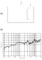
- FIG. 1 is a diagram for explaining the principle of the piezoelectric element.
- the piezoelectric element has a structure in which a capacitance layer is sandwiched between two electrode layers, and when a voltage is applied to the electrode layers, displacement occurs in the direction of the arrow shown in FIG.
- the audio reproduction device of the present embodiment functions as a so-called speaker by converting the displacement amount of the piezoelectric element into the vibration of air.
- the capacitance C of the piezoelectric element is assumed to be the relative permittivity ⁇ of the dielectric constituting the capacitance layer, the distance d between the electrodes, and the area S of the electrodes.
- C ⁇ S / d Has a relationship of.
- the impedance Z decreases as the capacitance C increases. Therefore, an increase in the capacitance C indicates that the sensitivity to voltage is improved, that is, the larger the capacitance C, the easier it is to obtain a large sound pressure as an audio reproduction device.
- the displacement amount ⁇ L generated when the voltage V is applied between the electrode layers is given as follows, where d is the distance between the electrode layers.
- ⁇ L a * V * L / d
- a is a piezoelectric strain constant, which is a strain generated when a unit electric field is applied in a state of zero stress. Therefore, in order to obtain a larger displacement amount ⁇ L, it can be seen that the distance d between the electrode layers is small, that is, a thin film is used.
- the audio playback device of the present embodiment uses an audio device formed by using a thin film-shaped piezoelectric element (thin film material).
- This audio device has a plastic sheet shape, and when a voltage is applied, it expands and contracts in the surface direction of the sheet as shown in FIG. By converting this expansion and contraction into vibration of air, it can be used in an audio playback device.
- FIG. 2 shows the configuration of the audio reproduction device 4.
- the audio playback device 4 includes two audio devices 1a and 1b and a vibrated portion 2.
- the vibrated portion 2 is, for example, a member having plasticity, and is made of a material harder than the audio devices 1a and 1b.
- the vibrated portion 2 converts the vibrations of the audio devices 1a and 1b into the vibrations of air and emits sound.
- the vibrated portion 2 of the present embodiment has a flat shape, but may have a curved shape. Almost the entire surface of the audio devices 1a and 1b is fixed to the vibrated portion 2 by using an adhesive. In this way, the acoustic conversion efficiency is improved by bringing the substantially entire surfaces of the audio devices 1a and 1b into close contact with the vibrated portion 2.
- the vibrated portion 2 is a thin display panel such as a liquid crystal display panel, an organic EL, an electrophoresis type, or a twist ball type, and the audio devices 1a and 1b are fixed to the back surface thereof to emit sound. It is possible to form a possible display panel.
- the audio reproduction device 4 may have both a display function and a sound emitting function, or may use the vibrated portion 2 like a diaphragm of a speaker and have only a sound emitting function.
- the audio device 1a has electrode portions 14a and 14b, and signal lines 21a and 22a are connected to the electrode portions 14a and 14b, respectively.
- signal lines 21a and 22a are connected to the electrode portions 14a and 14b, respectively.
- an acoustic signal is input to the signal lines 21b and 22b.
- Stereo reproduction can be realized by inputting the left and right audio signals to the audio devices 1a and 1b, respectively.
- the displacement due to the application of voltage to the piezoelectric element is in the direction parallel to the surface of the piezoelectric element as shown by the arrow, and cannot be converted into air vibration as it is.
- the audio devices 1a and 1b of the present embodiment are formed by folding the piezoelectric sheet 11, and vibrate in a direction perpendicular to the surface in a state where the audio devices 1a and 1b and the vibrated portion 2 are integrated. It is possible. In addition, since the folds are laminated in a plurality of layers, the sound emission efficiency is improved.
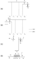
- FIG. 3 is a diagram showing a manufacturing process of the audio device 1.
- FIG. 4 is a flow chart showing a manufacturing process of the audio device 1.
- the audio device 1 of the present embodiment is formed by folding a piezoelectric sheet 11 (thin film material) and laminating it in a plurality of layers.
- the piezoelectric sheet 11 of the present embodiment has two electrode layers and a capacitance layer sandwiched between the electrode layers.
- the piezoelectric sheet 11 has a thickness of, for example, 30 ⁇ m to 100 ⁇ m, and preferably a thickness of 30 ⁇ m to 60 ⁇ m is used.
- a non-conductive protective layer made of PET or the like is provided on the surface layer side of the two electrode layers. Therefore, when connecting the signal line to the electrode layer, it is necessary to remove the protective layer at the connection portion to expose the electrode layer.
- various materials such as an electrostatic sheet can be used in addition to the piezoelectric sheet 11 as long as it is a thin film material having a capacitive characteristic. Is.
- the piezoelectric sheet 11 as a material is cut into the shapes shown in FIGS. 3 (A) and 3 (B) in the cutting step (S1). Note that FIG. 3B is the back surface of FIG. 3A.
- the portion indicated by the broken line is a portion to be a valley fold when folded in a later step, and the portion indicated by the alternate long and short dash line is a portion to be a mountain fold.
- Regions 11a to 11e are regions separated by broken lines (or alternate long and short dash lines).
- the cut piezoelectric sheet 11 is provided with an overhanging portion 13a in the rightmost region 11e. Further, a notch 12 is provided so as to be continuous with the upper side of the overhanging portion 13a. It is possible to provide the notch 12 and to make a portion located above the region 11e and connected to the region 11d as an overhanging portion 13b. The portion where the region 11d and the overhanging portion 13b are connected is not folded. With such a configuration, when the piezoelectric sheet is folded, the electrode portion 14a provided on the overhanging portion 13a and the electrode portion 14b provided on the overhanging portion 13b face the same side as shown in FIG. 3C. It has become like. Note that FIGS. 3A and 3B show locations where the electrode portions 14a and 14b are provided. The electrode portions 14a and 14b will be provided in a later step.
- the piezoelectric sheet 11 cut into the shapes of FIGS. 3 (A) and 3 (B) is wound into a cylindrical shape with the thermoplastic sheets stacked (S2).
- the thermoplastic sheet is arranged only in the region where the piezoelectric sheet 11 is laminated.
- a film-like hot melt adhesive containing a thermoplastic elastomer resin as a main component can be considered.
- the film-like hot melt adhesive containing a thermoplastic elastomer resin as a main component for example, Elfan, Eceran and the like are known. Since such a thermoplastic sheet has no adhesive strength at room temperature, it is easy to process.
- the thickness of the thermoplastic sheet is generally reduced after bonding, the thickness of the laminated sheet is not significantly increased.
- the adhesive layer may be either conductive or non-conductive.
- the piezoelectric sheet 11 and the thermoplastic sheet wound in a cylindrical shape are pressed and folded in the pressing step (S3) to form a laminated shape. Then, in the bonding / shape fixing step (S4), the laminated sheets (piezoelectric sheet 11 and the thermoplastic sheet) are heated at a temperature necessary for fusing the thermoplastic sheet.
- the heated thermoplastic sheet functions as an adhesive layer between the piezoelectric sheets 11 laminated by being heated.
- FIG. 3C is a front view of the audio device 1 when the manufacturing process is completed
- FIG. 3D is a cross-sectional view of FIG. 3C.
- the cross-sectional view of FIG. 3D is schematically shown stretched in the thickness direction in order to facilitate understanding of the layer structure.
- an electrode portion 14a is formed in the overhanging portion 13a, and another electrode portion 14b is formed in the overhanging portion 13b.
- the piezoelectric sheet 11 needs to have electrode portions 14a and 14b formed on the front and back surfaces thereof, but the piezoelectric sheet 11 of the present embodiment utilizes folding so that the two electrode portions 14a and 14b are on the same surface side. It is exposed to. Further, as shown in FIG. 3C, since the electrode portions 14a and 14b are arranged at positions not adjacent to each other, it is possible to prevent a short circuit between the electrode portions 14a and 14b during wiring or the like. It has become.
- the back surfaces of the overhanging portions 13a and 13b made of the piezoelectric sheet 11 can also be fixed to the vibrated portion 2, and the area where the audio device 1 is in close contact with the vibrated portion 2 is increased to improve the acoustic conversion efficiency. Improvements are also being made.
- the piezoelectric sheet 11 and the thermoplastic sheet are wound into a cylindrical shape in a state of being overlapped with each other.
- the piezoelectric sheet 11 is wound in a spiral shape.
- an adhesive layer 15 made of a molten thermoplastic sheet is formed between the five layers formed by the regions 11a to 11e of the piezoelectric sheet 11.
- the audio device 1 formed in such a process has substantially the entire surface fixed to the vibrated portion 2.
- the back surfaces of the overhanging portions 13a and 13b provided with the electrode portions 14a and 14b are also fixed to the vibrated portion 2, and the area in which the audio device 1 is in close contact with the vibrated portion 2 is increased. The sound conversion efficiency has been improved.
- 5 and 6 are diagrams showing the configuration and frequency characteristics of the audio reproduction device 4.
- the size of the audio device 1 used, the number of layers, and the like are different, and changes in the frequency characteristics are observed.
- the audio reproduction device 4 has an audio device 1 bonded to the right side of the center of the vibrated portion 2.
- the configuration of the audio device 1 has a long side (vertical) 400 mm, a short side (horizontal) 80 mm, and a three-layer structure. Therefore, the area of the piezoelectric sheet 11 used in the audio device 1 of FIG. 5A is 0.096 m 2 .
- FIG. 5 (B) shows the frequency characteristics of the audio reproduction device 4 of FIG. 5 (A).
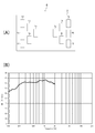
- FIG. 6A is a diagram showing a configuration of an audio playback device 4 to be compared.
- the audio reproduction device 4 shown in FIG. 6A has an audio device 1 bonded to the right side with respect to the center of the vibrated portion 2.
- the configuration of the audio device 1 has a long side (length) of 100 mm, a short side (horizontal) of 50 mm, and a seven-layer structure. Therefore, the area of the piezoelectric sheet 11 used in the audio device 1 of FIG. 6 (A) is 0.035 m 2 .
- the audio device 1 used in FIG. 6 (A) is smaller than the audio device 1 in FIG. 5 (A), but has a structure having a large number of layers, that is, a structure having a large number of folds. ..
- FIG. 6 (B) shows the frequency characteristics of the audio playback device 4 of FIG. 6 (A).
- the area of the piezoelectric sheet 11 is about 1 / due to the structure having a large number of layers in FIG. 6 (B). It can be confirmed that the sound pressure substantially the same as that in FIG. 6B is obtained even though the frequency is about 3. In particular, at 200 Hz to 1 kHz, it can be confirmed that the sound pressure is higher than that in FIG. 5 (B).
- the audio reproduction device 4 it is possible to improve the acoustic characteristics and secure the necessary sound pressure by increasing the number of layers by folding the audio device 1.
- the audio reproduction device 4 has audio devices 1a and 1b bonded to the left side and the right side of the center of the vibrated portion 2, respectively.
- the configurations of the audio devices 1a and 1b have a three-layer structure with a long side (vertical) of 400 mm and a short side (horizontal) of 80 mm.
- FIG. 7B shows the frequency characteristics of the audio reproduction device 4 of FIG. 7A.
- FIG. 8A is a diagram showing the configuration of the audio playback device 4 to be compared.
- the audio reproduction device 4 shown in FIG. 8A has six audio devices 1a to 1f bonded to the left side of the center of the vibrated portion 2. At that time, the number of audio devices 1a to 1f is reduced from the left end toward the center. Further, 6 audio devices 1g to 1l are adhered to the right side of the center of the vibrated portion 2. The audio devices 1g to 1l arranged on the right side are arranged so as to be symmetrical with the audio devices 1a to 1f arranged on the left side.
- the audio devices 1a to 1l are driven by the left channel, and the audio devices 1g to 1l located on the right side are driven by the right channel.
- the left and right acoustic signals interfere with each other near the center of the vibrated portion 2, but the number of audio devices 1a and 1g arranged near the center The reason is that by reducing the amount, interference on the vibrated portion 2 can be suppressed.
- the configuration of the audio devices 1a to 1l (12 devices) used in FIG. 8A has a long side (length) of 100 mm, a short side (width) of 50 mm, and a seven-layer structure.
- FIG. 8B shows the frequency characteristics of the audio reproduction device 4 of FIG. 8A.
- each area of the piezoelectric sheet 11 for use in audio devices 1a, 1b is 0.096M 2, a total of 0.192M 2 by using two.
- the respective area of the piezoelectric sheet 11 for use in audio devices 1a ⁇ 1l are 0.035 m 2, a total of 0.42 m 2 by using 12 sheets.
- the area is 2.2 times larger than that of FIG. 7 (A), but in the calculated area of 2.2 times, the sound pressure can be improved by about 9 dB, depending on the frequency band. Is seen to improve by 10 to 20 dB.
- the audio reproduction device 4 is configured by using a plurality of audio devices 1 in order to increase the sound pressure
- increasing the total area of the piezoelectric sheet 11 in order to improve the sensitivity is consistent in principle.
- the sound pressure of the vibrated portion 2 can be improved more efficiently by downsizing the audio device 1 and increasing the number of layers.
- FIG. 9 is a diagram showing a manufacturing process and a structure of the audio device 1 for the second embodiment.
- the piezoelectric sheet 11 used in the audio device 1 is cut into the same shape as the audio device 1 described in FIG.
- the audio devices 1 in FIG. 3 differ in the way they are stacked.
- the audio device 1 of the second embodiment has mountain folds and valley folds in the adjacent regions 11a to 11e.
- the bent structure has a structure in which adjacent regions 11a to 11e are arranged in order as shown in FIG. 9D to form a layer.
- four thermoplastic sheets are used between each layer, and each layer is fused to form four adhesive layers 15a to 15d.
- each layer can be fused even if the thermoplastic sheets are arranged on both sides that form the valley surface.
- thermoplastic sheets may be arranged on both sides of 11b and 11c.
- thermoplastic sheets may be arranged on both sides of 11d and 11e, 11d and 11c in FIG. 9B, and 11b and 11a.
- the audio reproduction device 4 is configured by using a plurality of audio devices 1 in order to increase the sound pressure
- increasing the total area of the piezoelectric sheet 11 in order to improve the sensitivity is consistent in principle.
- the sound pressure of the vibrated portion 2 can be improved more efficiently.
- FIG. 10 is a diagram showing a manufacturing process and a structure of the audio device 1 for the third embodiment.
- the piezoelectric sheet 11 is divided into five regions 11a to 11e and folded, and all folding methods are valley folds as shown in FIG. 10 (A).
- FIG. 10D the piezoelectric sheet 11 is in a spirally wound state as in the first embodiment.
- narrow overhanging portions 13b and 13a are provided in the regions 11d and 11e. Then, the electrode portion 14a is formed on one surface of the overhanging portion 13a, and the electrode portion 14b is formed on the other surface of the overhanging portion 13b.
- the overhanging portion 13a and the overhanging portion 13b can be brought into a state of being adjacent to each other with a gap. It is possible. Further, in this state, the electrode portions 14a and 14b face the same side of the audio device 1. Therefore, it is easy to wire the signal lines to the electrode portions 14a and 14b and to route the signal lines.
- FIG. 11 is a diagram showing a manufacturing process and a structure of the audio device 1 with respect to the fourth embodiment.
- the piezoelectric sheet 11 is divided into five regions 11a to 11e and folded, and all folding methods are valley folds as shown in FIG. 11A.
- the piezoelectric sheet 11 is in a spirally wound state as in the first embodiment.
- the overhanging portions 13a and 13b are provided in the regions 11e and 11d.
- the overhanging portions 13a and 13b have a shape that also overhangs in the lateral direction.
- the overhanging portions 13a and 13b are in a state of protruding to different sides as shown in FIG. 11D. Therefore, it is possible to take a large area of the overhanging portions 13a and 13b, facilitating wiring, and for example, by taking a large fixed area by soldering, it is possible to firmly fix the signal line. There is. Further, as in the third embodiment, it is possible to provide a sufficient space between the overhanging portions 13a and 13b to suppress a short circuit during wiring.
- FIG. 12 is a diagram showing a manufacturing process and a structure of the audio device 1 with respect to the fifth embodiment.
- the piezoelectric sheet 11 is divided into five regions 11a to 11e and folded, and all folding methods are valley folds as shown in FIG. 12 (A).
- FIG. 12D the piezoelectric sheet 11 is in a spirally wound state as in the first embodiment.
- overhanging portions 13a and 13b are provided in the regions 11e and 11d.
- the overhanging portion 13b is profitable by providing a notch 12 in the region 11e adjacent to the region 11d and biting into the region 11e.
- the overhanging portions 13a and 13b are in a state of overhanging to different sides, and the electrode portions 14a located on the same side of the audio device 1 , It is possible to take a large interval between 14b. Therefore, the wiring of the signal line and the routing of the signal line are made easy.
- the yield when cutting out the piezoelectric sheet 11, that is, the number of pieces that can be cut out from the large-sized piezoelectric sheet 11 is improved. Is possible.
- the adhesive layer is formed by pressing the thermoplastic sheet in a sandwiched state, but the formation of the adhesive layer is not limited to the form in which the thermoplastic sheet is used in this way. It is possible to adopt various modified examples.
- spray glue may be used for the adhesive layer.
- spray glue it is possible to form an adhesive layer by spraying the spray glue on the surface to be adhered to the piezoelectric sheet 11 and pressing the adhesive layer.
- the adhesive layer for example, a double-sided tape having adhesive layers on both sides of the reinforcing layer may be used. By providing the reinforcing layer, it is possible to improve the strength of the formed audio device 1.
- double-sided tape may be used for the adhesive layer.
- the audio device 1 can be easily formed by crimping with the double-sided tape sandwiched between them.
- glue adheresive
- FIG. 13 is an example showing the arrangement of the audio devices 1a to 1j in the audio reproduction device 4. Note that, in FIG. 13, wiring to the audio devices 1a to 1j is omitted as in FIGS. 5 to 8.
- the audio devices 1a to 1j may be arranged in a plurality of pairs, for example, the audio device 1a and the audio device 1f are arranged side by side as a pair. In the arrangement example of FIG. 13, pairs of audio devices are arranged in the vertical direction. In this way, when arranging a plurality of sheets, the sound pressure and acoustic characteristics suitable for the system can be adjusted by increasing or decreasing the number of sheets, the orientation of the arrangement, the arrangement position with respect to the vibrated portion 2, and the like.
- the audio devices 1a to 1j used in FIG. 13 are created, for example, in the form described in FIG. 3, so that the electrode portions 14a and the electrode portions 14b face the same surface side of the audio devices 1a to 1j. You may. Alternatively, the electrode portion 14a and the electrode portion 14b may be configured to face different surfaces of the audio devices 1a to 1j.
- a plurality of audio devices 1a to 1f are used for the same channel, but they are used for the same channel.
- the areas of the audio devices 1a to 1f (or 1g to 1l) may be different. By having different areas of the audio devices 1a to 1f (or 1g to 1l), it is possible to make the frequency characteristics different, and it is possible to realize suitable frequency characteristics as a whole.
- a signal whose frequency is partially cut off may be input.
- 1d and 1j having a symmetrical relationship in FIG. 8 low frequencies are cut off and used as high frequency channels (1d is the left channel and 1j is the right channel).
- each audio device 1a to 1f (or 1g to 1l) is made different, and some frequencies are used according to the area of each audio device 1a to 1f (or 1g to 1l).
- the signal that is cut off may be input.
- the present disclosure can be similarly applied to a flexible material such as a roll-up screen such as a projector screen or a self-standing screen as the vibrated portion 2.
- the present disclosure can also be applied to a large screen such as a theater in the same manner. Further, the present disclosure can be applied in the same manner even if there is a portion penetrating as the vibrated portion 2 such as a screen having a small through hole. It is also possible to efficiently transmit sound to the surface opposite to the surface on which the audio device 1 is provided through the through hole provided in the vibrated portion 2.
- the present disclosure may also adopt the following configuration.
- a plurality of layer structures were formed by folding a plurality of thin film materials having a first electrode layer, a second electrode layer, and a capacitance layer sandwiched between the first electrode layer and the second electrode layer.
- An audio playback device including a vibrated portion that is bendable and to which one side of the audio device is fixed.
- the audio playback device according to (1) wherein one surface of the audio device is fixed so as to be in close contact with the vibrated portion.
- the audio playback device according to any one of (1) to (3), wherein the thin film material is folded in a spiral shape to form a plurality of layer structures.
- the audio reproduction device according to any one of (1) to (4), wherein the thin film material has electrode portions formed on each of the first electrode layer and the second electrode layer.
- the audio reproduction device according to (5), wherein the first electrode layer and the second electrode layer are provided on the same side in a state where the thin film material is folded and folded.
- the audio playback device according to any one of (1) to (6), which is a display panel.
- the audio playback device according to any one of (1) to (7), which has a plurality of the audio devices.
- a plurality of layer structures are formed by folding a plurality of thin film materials having a first electrode layer, a second electrode layer, and a capacitance layer sandwiched between the first electrode layer and the second electrode layer. An audio device that is fixed to a vibrated part that can be curved on one side.
- Audio device 2 Vibrated part 4: Audio reproduction device 11: Piezoelectric sheet 11a to 11e: Region 12: Notch 13a, 13b: Overhanging part 14a, 14b: Electrode part 15 (15a to 15d): Adhesive layers 21a, 21b: signal lines 22a, 22b: signal lines
Landscapes
- Engineering & Computer Science (AREA)
- Physics & Mathematics (AREA)
- Acoustics & Sound (AREA)
- Signal Processing (AREA)
- Multimedia (AREA)
- Piezo-Electric Transducers For Audible Bands (AREA)
Priority Applications (3)
| Application Number | Priority Date | Filing Date | Title |
|---|---|---|---|
| US17/613,008 US20220210578A1 (en) | 2019-05-27 | 2020-04-03 | Audio reproduction apparatus and audio device |
| JP2021522669A JPWO2020241049A1 (https=) | 2019-05-27 | 2020-04-03 | |
| CN202080032614.1A CN113767646A (zh) | 2019-05-27 | 2020-04-03 | 音频再现装置和音频设备 |
Applications Claiming Priority (2)
| Application Number | Priority Date | Filing Date | Title |
|---|---|---|---|
| JP2019-098438 | 2019-05-27 | ||
| JP2019098438 | 2019-05-27 |
Publications (1)
| Publication Number | Publication Date |
|---|---|
| WO2020241049A1 true WO2020241049A1 (ja) | 2020-12-03 |
Family
ID=73553391
Family Applications (1)
| Application Number | Title | Priority Date | Filing Date |
|---|---|---|---|
| PCT/JP2020/015307 Ceased WO2020241049A1 (ja) | 2019-05-27 | 2020-04-03 | オーディオ再生装置及びオーディオデバイス |
Country Status (4)
| Country | Link |
|---|---|
| US (1) | US20220210578A1 (https=) |
| JP (1) | JPWO2020241049A1 (https=) |
| CN (1) | CN113767646A (https=) |
| WO (1) | WO2020241049A1 (https=) |
Cited By (1)
| Publication number | Priority date | Publication date | Assignee | Title |
|---|---|---|---|---|
| WO2023048022A1 (ja) * | 2021-09-24 | 2023-03-30 | 富士フイルム株式会社 | 圧電素子および圧電スピーカー |
Citations (4)
| Publication number | Priority date | Publication date | Assignee | Title |
|---|---|---|---|---|
| JPH05122793A (ja) * | 1991-10-25 | 1993-05-18 | Murata Mfg Co Ltd | 圧電スピーカ |
| JPH11112046A (ja) * | 1997-09-30 | 1999-04-23 | Kyocera Corp | 圧電アクチュエータ及びその製造方法 |
| JP2015070110A (ja) * | 2013-09-30 | 2015-04-13 | 株式会社村田製作所 | 圧電デバイスおよび圧電デバイスの製造方法 |
| JP2016100760A (ja) * | 2014-11-21 | 2016-05-30 | 京セラ株式会社 | 圧電素子、圧電振動装置、音響発生器、音響発生装置および電子機器 |
Family Cites Families (5)
| Publication number | Priority date | Publication date | Assignee | Title |
|---|---|---|---|---|
| US4330730A (en) * | 1980-03-27 | 1982-05-18 | Eastman Kodak Company | Wound piezoelectric polymer flexure devices |
| US4725994A (en) * | 1984-06-14 | 1988-02-16 | Kabushiki Kaisha Toshiba | Ultrasonic transducer with a multiple-folded piezoelectric polymer film |
| US5796854A (en) * | 1997-03-04 | 1998-08-18 | Compaq Computer Corp. | Thin film speaker apparatus for use in a thin film video monitor device |
| US9407995B2 (en) * | 2012-08-30 | 2016-08-02 | Kyocera Corporation | Acoustic generator, acoustic generation device, and electronic device |
| KR102668290B1 (ko) * | 2018-12-11 | 2024-05-23 | 삼성디스플레이 주식회사 | 표시 장치와 그의 구동 방법 |
-
2020
- 2020-04-03 JP JP2021522669A patent/JPWO2020241049A1/ja active Pending
- 2020-04-03 CN CN202080032614.1A patent/CN113767646A/zh not_active Withdrawn
- 2020-04-03 US US17/613,008 patent/US20220210578A1/en not_active Abandoned
- 2020-04-03 WO PCT/JP2020/015307 patent/WO2020241049A1/ja not_active Ceased
Patent Citations (4)
| Publication number | Priority date | Publication date | Assignee | Title |
|---|---|---|---|---|
| JPH05122793A (ja) * | 1991-10-25 | 1993-05-18 | Murata Mfg Co Ltd | 圧電スピーカ |
| JPH11112046A (ja) * | 1997-09-30 | 1999-04-23 | Kyocera Corp | 圧電アクチュエータ及びその製造方法 |
| JP2015070110A (ja) * | 2013-09-30 | 2015-04-13 | 株式会社村田製作所 | 圧電デバイスおよび圧電デバイスの製造方法 |
| JP2016100760A (ja) * | 2014-11-21 | 2016-05-30 | 京セラ株式会社 | 圧電素子、圧電振動装置、音響発生器、音響発生装置および電子機器 |
Cited By (1)
| Publication number | Priority date | Publication date | Assignee | Title |
|---|---|---|---|---|
| WO2023048022A1 (ja) * | 2021-09-24 | 2023-03-30 | 富士フイルム株式会社 | 圧電素子および圧電スピーカー |
Also Published As
| Publication number | Publication date |
|---|---|
| CN113767646A (zh) | 2021-12-07 |
| JPWO2020241049A1 (https=) | 2020-12-03 |
| US20220210578A1 (en) | 2022-06-30 |
Similar Documents
| Publication | Publication Date | Title |
|---|---|---|
| JP5511930B2 (ja) | 圧電振動装置 | |
| CN105874624B (zh) | 压电元件以及具备其的压电振动装置、便携式终端、声音发生器、声音发生装置、电子设备 | |
| CN103155410B (zh) | 压电振动装置 | |
| CN105027581B (zh) | 压电致动器及具备其的压电振动装置、便携式终端、声音发生器、声音发生装置、电子设备 | |
| KR101523535B1 (ko) | 압전소자, 그리고 이것을 구비한 압전 진동장치, 휴대단말, 음향 발생기, 음향 발생장치 및 전자기기 | |
| US12075211B2 (en) | Laminated piezoelectric element and electroacoustic transducer | |
| JP5404970B1 (ja) | 圧電振動部品および携帯端末 | |
| JP5730452B1 (ja) | 圧電アクチュエータおよびこれを備えた圧電振動装置、携帯端末、音響発生器、音響発生装置、電子機器 | |
| WO2013081078A1 (ja) | 静電型スピーカ | |
| WO2020241049A1 (ja) | オーディオ再生装置及びオーディオデバイス | |
| JP2015185819A (ja) | バイモルフ型圧電素子の駆動装置およびこれを備えた携帯端末、音響発生器、音響発生装置、電子機器 | |
| JP2015207740A (ja) | 圧電アクチュエータ、圧電振動装置、携帯端末、音響発生器、音響発生装置および電子機器 | |
| JP6215746B2 (ja) | 音響発生器およびこれを備えた音響発生装置、電子機器、携帯端末 | |
| JP6920188B2 (ja) | 圧電素子、音響発生器および電子機器 | |
| JP5225518B1 (ja) | 圧電振動素子,圧電振動装置および携帯端末 | |
| JP6189648B2 (ja) | 圧電振動素子ならびにそれを用いた圧電振動装置および携帯端末 |
Legal Events
| Date | Code | Title | Description |
|---|---|---|---|
| 121 | Ep: the epo has been informed by wipo that ep was designated in this application |
Ref document number: 20812684 Country of ref document: EP Kind code of ref document: A1 |
|
| ENP | Entry into the national phase |
Ref document number: 2021522669 Country of ref document: JP Kind code of ref document: A |
|
| NENP | Non-entry into the national phase |
Ref country code: DE |
|
| 122 | Ep: pct application non-entry in european phase |
Ref document number: 20812684 Country of ref document: EP Kind code of ref document: A1 |