WO2020236607A1 - Firearm discharge location systems and methods - Google Patents
Firearm discharge location systems and methods Download PDFInfo
- Publication number
- WO2020236607A1 WO2020236607A1 PCT/US2020/033167 US2020033167W WO2020236607A1 WO 2020236607 A1 WO2020236607 A1 WO 2020236607A1 US 2020033167 W US2020033167 W US 2020033167W WO 2020236607 A1 WO2020236607 A1 WO 2020236607A1
- Authority
- WO
- WIPO (PCT)
- Prior art keywords
- microphones
- pair
- firearm discharge
- location
- pairs
- Prior art date
- Legal status (The legal status is an assumption and is not a legal conclusion. Google has not performed a legal analysis and makes no representation as to the accuracy of the status listed.)
- Ceased
Links
Classifications
-
- G—PHYSICS
- G01—MEASURING; TESTING
- G01S—RADIO DIRECTION-FINDING; RADIO NAVIGATION; DETERMINING DISTANCE OR VELOCITY BY USE OF RADIO WAVES; LOCATING OR PRESENCE-DETECTING BY USE OF THE REFLECTION OR RERADIATION OF RADIO WAVES; ANALOGOUS ARRANGEMENTS USING OTHER WAVES
- G01S5/00—Position-fixing by co-ordinating two or more direction or position line determinations; Position-fixing by co-ordinating two or more distance determinations
- G01S5/18—Position-fixing by co-ordinating two or more direction or position line determinations; Position-fixing by co-ordinating two or more distance determinations using ultrasonic, sonic or infrasonic waves
- G01S5/22—Position of source determined by co-ordinating a plurality of position lines defined by path-difference measurements
-
- G—PHYSICS
- G01—MEASURING; TESTING
- G01S—RADIO DIRECTION-FINDING; RADIO NAVIGATION; DETERMINING DISTANCE OR VELOCITY BY USE OF RADIO WAVES; LOCATING OR PRESENCE-DETECTING BY USE OF THE REFLECTION OR RERADIATION OF RADIO WAVES; ANALOGOUS ARRANGEMENTS USING OTHER WAVES
- G01S3/00—Direction-finders for determining the direction from which infrasonic, sonic, ultrasonic or electromagnetic waves, or particle emission, not having a directional significance, are being received
- G01S3/80—Direction-finders for determining the direction from which infrasonic, sonic, ultrasonic or electromagnetic waves, or particle emission, not having a directional significance, are being received using ultrasonic, sonic or infrasonic waves
- G01S3/802—Systems for determining direction or deviation from predetermined direction
- G01S3/808—Systems for determining direction or deviation from predetermined direction using transducers spaced apart and measuring phase or time difference between signals therefrom, i.e. path-difference systems
-
- G—PHYSICS
- G01—MEASURING; TESTING
- G01S—RADIO DIRECTION-FINDING; RADIO NAVIGATION; DETERMINING DISTANCE OR VELOCITY BY USE OF RADIO WAVES; LOCATING OR PRESENCE-DETECTING BY USE OF THE REFLECTION OR RERADIATION OF RADIO WAVES; ANALOGOUS ARRANGEMENTS USING OTHER WAVES
- G01S5/00—Position-fixing by co-ordinating two or more direction or position line determinations; Position-fixing by co-ordinating two or more distance determinations
- G01S5/18—Position-fixing by co-ordinating two or more direction or position line determinations; Position-fixing by co-ordinating two or more distance determinations using ultrasonic, sonic or infrasonic waves
-
- G—PHYSICS
- G01—MEASURING; TESTING
- G01S—RADIO DIRECTION-FINDING; RADIO NAVIGATION; DETERMINING DISTANCE OR VELOCITY BY USE OF RADIO WAVES; LOCATING OR PRESENCE-DETECTING BY USE OF THE REFLECTION OR RERADIATION OF RADIO WAVES; ANALOGOUS ARRANGEMENTS USING OTHER WAVES
- G01S2205/00—Position-fixing by co-ordinating two or more direction or position line determinations; Position-fixing by co-ordinating two or more distance determinations
- G01S2205/01—Position-fixing by co-ordinating two or more direction or position line determinations; Position-fixing by co-ordinating two or more distance determinations specially adapted for specific applications
- G01S2205/06—Emergency
-
- H—ELECTRICITY
- H04—ELECTRIC COMMUNICATION TECHNIQUE
- H04R—LOUDSPEAKERS, MICROPHONES, GRAMOPHONE PICK-UPS OR LIKE ACOUSTIC ELECTROMECHANICAL TRANSDUCERS; ELECTRIC HEARING AIDS; PUBLIC ADDRESS SYSTEMS
- H04R1/00—Details of transducers, loudspeakers or microphones
- H04R1/08—Mouthpieces; Microphones; Attachments therefor
-
- H—ELECTRICITY
- H04—ELECTRIC COMMUNICATION TECHNIQUE
- H04R—LOUDSPEAKERS, MICROPHONES, GRAMOPHONE PICK-UPS OR LIKE ACOUSTIC ELECTROMECHANICAL TRANSDUCERS; ELECTRIC HEARING AIDS; PUBLIC ADDRESS SYSTEMS
- H04R3/00—Circuits for transducers
Definitions
- This disclosure relates to firearm discharge location systems and methods.
- Incidents involving active shooters which include shootings in confined environments, such as a school or classroom, shopping mall, airport, train station as well as in open spaces have been increasing yearly and some statistics indicate that a life is lost every 1 5 seconds due to shootings.
- Rapid identification of the location of a firearm discharge allows first responders to locate and engage the shooter as quickly as possible as well as search for potential victims.
- Information related to the detection and location of the shooter can be some of the most critical information provided to first responders.
- Firearm discharges such as gunshots are significant energy events having both large audio decibel levels and long signal durations of up to half a second. Both of these attributes are enhanced by reflections from walls, ceilings, floors and other items, which can increase signal du ration by the associated delayed arrival of the signal multi-paths.
- the large amounts of energy released by a weapon discharge also generate significant nonlinearities which can result in the generation of higher harmonics and signal perturbations.
- the sou nd of the firearm discharge itself, the sou nd of the bullet impacting an object, the proximity or distance from the gu nshot, and reflections off of other objects can all impact the shock wave or shock front from the firearm discharge and provide distortion.
- aspects of the present disclosure described below are directed to firearm discharge location systems and related methods that enable accurate determination of a location of a firearm discharge.
- Fig. 1 is an illustrative representation of a firearm discharge location system according to one embodiment.
- Figs. 2A-2D are graphical representations of intersecting hyperbolas according to one embodiment.
- Fig. 3 is an illustrative representation of a microphone array according to one embodiment.
- Fig. 4 is an illustrative representation of a microphone array and associated circuitry according to one embodiment.
- Fig. 5 is an illustrative representation of a microphone array and associated circuitry according to one embodiment.
- Fig. 6 is an illustrative representation of a quad array including two non-parallel pairs of synchronized microphones according to one embodiment.
- Fig. 7 is an illustrative representation of an octagonal array including four non-parallel pairs of synchronized microphones according to one embodiment.
- the present disclosure is directed to sensor systems and associated methods that can detect and analyze firearm discharges in multiple environments, including both confined environments as well as open outdoor environments, and determine additional information, such as location of the firearm discharge (e.g., gunshot) and the nu mber of rounds fired.
- location of the firearm discharge e.g., gunshot
- nu mber of rounds fired e.g., gunshot
- plural intersecting hyperbolas and acoustic source localization are used to identify the location of a shooter within an area being monitored.
- the system 1 0 includes a microphone array 1 2, a plurality of analog-to-digital converters (ADCs) 20, a plurality of clocks 22, processing circuitry 24, a comparator 25, a user interface 26 and a timer 27 in the illustrated configu ration.
- ADCs analog-to-digital converters
- clocks a plurality of clocks 22
- processing circuitry a comparator 25
- user interface 26 a user interface 26
- timer 27 in the illustrated configu ration.
- Other embodiments are possible including more, less and/or alternative components.
- microphone array 1 2 is configu red as a quad microphone array including four microphones 14-1 7 that are spaced from one another in two dimensions and positioned to receive acoustic signals from an indoor or outdoor area 1 8 being monitored.
- Example microphones that may be utilized include either model nu mber VM1 000 or VM3000 available from Vesper Technologies Inc., or a model INMP404 available from TDK InvenSense.
- the microphones 14-1 7 are arranged generally in the shape of a cross in the depicted embodiment.
- the acoustic signals received by the microphone array 12 are processed to provide information regarding a location of a shooter/firearm discharge within area 1 8 (as well as determining locations of firearm discharges within regions adjacent to area 1 8).
- the illustrated microphones 14-17 of the array 12 are positioned at a preselected distance (i.e., microphone spacing parameter c) from an origin or center 19 and monitor the area 18 generally in the shape of a square in the illustrated embodiment.
- Microphones 14-1 7 are located at midpoints of the sides of the square area 18 in Fig. 1 .
- the area 1 8 within a perimeter defined by the placement of microphones 14-1 7 is the primary area to be monitored although system 10 can process signals received by the microphones 14-1 7 that originate from outside of the area 18 if the acoustic wave of the firearm discharge outside of area 18 is received by microphones 14-17.
- System 10 has increased sensitivity and accu racy for locating firearm discharges that occur within area 1 8 compared with those that originate outside of area 18, and in typical applications, the placement of the microphones 14-1 7 defines the perimeter of the primary area to be monitored.
- the system 1 0 may be utilized in many different applications and monitor areas 18 of many different sizes.
- the values of microphone spacing parameter c may vary greatly depending upon the application, for example from 0.5 m to hu ndreds or perhaps thousands of meters depending upon the sensitivity of the microphones to receive acoustic waveforms of sufficient energy from firearm discharges.
- ADCs 20 are each coupled with a respective one of the microphones 14-1 7 via a plurality of wired connections 21 in one embodiment. Connections 21 are coupled with signal inputs of the ADCs 20 and ADCs 20 sample analog electrical signals from the microphones 14-1 7 to provide a plurality of digital data samples to implement data capture operations with respect to microphones 14-1 7 in the described embodiment. In one embodiment, ADCs 20 are each implemented using model ADC12DL080 available from Texas Instru ments.
- the microphone array 1 2 is arranged adjacent to the area 18 to be monitored and the remaining components of system 10 are implemented in a base station (not shown).
- the ADCs 20 may be co located with the respective microphones 14-17 and wireless clock signals from clocks 22 in the base station may be commu nicated to the respective ADCs 20 and data samples from the ADCs 20 may be wirelessly communicated to comparator 25 in the base station in one embodiment.
- Microphone array 12 includes plural independent (i.e., asynchronous) pairs of synchronized microphones in one embodiment.
- timing circuitry provides a plurality of independent clock signals to independently synchronize respective pairs of the microphones in the described embodiment.
- One arrangement of the timing circuitry includes a plu rality of independent clocks 22 configured to generate a plurality of independent asynchronous timing or clock signals or references.
- clocks 22 are each configu red to generate an independent clock signal having the same frequency within an example range of 1 -40 MHz.
- the clock and sampling frequency is determined by location precision requirements and maximum allowed separation between the microphones within each pair. If the microphones pairs are close together (e.g., less than 1 m) a frequency in the upper end of the range may be utilized and if the microphones of a pair are further apart (e.g., greater than 1 m), a frequency in the lower range may be utilized.
- a first of pair of the microphones 14, 1 6 receive a first timing reference from a first of the clocks 22 and the first timing reference operates to synchronize data capture operations of the first pair of microphones 14, 16.
- the data capture operations include sampling of analog signals outputted from the microphones 14, 1 6 to generate a plurality of data samples in one embodiment.
- the first pair of microphones 14, 1 6 is oriented along an axis that is orthogonal or at a right angle with respect to an axis of the second pair of microphones 1 5, 17.
- microphones 14, 16 of the first pair are located at opposite first and second sides of the square area 1 8 and the microphones 15, 17 of the second pair are located at opposite third and fou rth sides of the square area 1 8.
- the first and second pairs of microphones are co-located in the depicted embodiment.
- the first timing reference controls the timing of the data conversion operations of the first and third ADCs 20 and corresponding sampling of signals from respective microphones 14, 1 6.
- the data capture operations of the first pair of microphones 14, 1 6 are considered to be synchronized with one another.
- Fu rthermore the data capture operations of a second pair of microphones 1 5, 17 are considered to be synchronized with one another using a second timing reference in the illustrated embodiment.
- the data capture operations of the first and second pairs of microphones are considered to be asynchronous with respect to one another in the described embodiment.
- Data capture operations of the first pair of microphones 14, 16 are synchronized with the first timing reference and are asynchronous with respect to data capture operations of the second pair of microphones 1 5, 1 7 that are synchronized with the second timing reference.
- the electronics utilized for determination of the location of the firearm discharge may be simplified if synchronization of all microphones of the array 12 is not implemented in some embodiments discussed herein.
- processing circuitry 24 is configu red to implement desired programming provided by appropriate computer- readable storage media in at least one embodiment.
- the processing circuitry 24 may be implemented as one or more processor(s) and/or other structu re configured to execute executable instructions including, for example, software and/or firmware instructions.
- Other example embodiments of processing circuitry 24 include hardware logic, PGA, FPGA, ASIC, state machines, and/or other structures alone or in combination with one or more processor(s). These examples of processing circuitry 14 are for illustration and other configu rations are possible.
- Processing circuitry 24 accesses storage circuitry (not shown) that is configured to store programming, such as executable code or instructions (e.g., software and/or firmware), electronic data, databases, or other digital information and may include computer- readable storage media. At least some embodiments or aspects described herein may be implemented using programming stored within storage circuitry and configured to control appropriate processing circuitry 24.
- programming such as executable code or instructions (e.g., software and/or firmware), electronic data, databases, or other digital information and may include computer- readable storage media.
- At least some embodiments or aspects described herein may be implemented using programming stored within storage circuitry and configured to control appropriate processing circuitry 24.
- processing circuitry 24 also controls other operations of firearm discharge location system 1 0 including data access and storage, and generation of information regarding the position of a shooter as a result of the processing of the signals from the microphones 14-1 7.
- User interface 26 is configu red to interact with a user including conveying data to a user.
- user interface 26 may include a display to depict visual images for observation by the user as well as an input device configured to receive inputs from the user.
- the user interface 26 generates a visual image of the area being monitored by the system and displays the location of the firearm discharge within the visual image of the area.
- User interface 26 may alternatively or additionally display the co-ordinates of the location of the determined firearm discharge.
- timer 27 is implemented as a 16-bit that perpetually counts up and rolls over when reaching its maximum value.
- the timer 27 increments values at a frequency of approximately 1 MHz in implementation.
- the output of timer 27 is utilized to generate a plurality of time stamps as described below.
- processing circuitry 24 is configured to use outputs of the microphones 14-17 to identify a location of a firearm discharge as described further below.
- the ADCs 20 are connected to a low-latency input of a comparator 25.
- Comparator 25 compares data samples outputted by the ADCs 20 to a threshold selected to filter out or remove acoustic waves received by the microphones 14-1 7 having intensities less than those resulting from a firearm discharge.
- Processing circuitry 24 is configu red to continuously monitor outputs of comparator 25 from the microphones 14-1 7 to determine if any of the data samples from the microphones 14- 17 triggered the threshold.
- the processing circuitry 24 records the event along with an associated time stamp from timer 27 indicating the moment in time when the data sample from one of the microphones 14-1 7 triggered the comparator 25 as well as an indication of the specific microphone 14-17 from which the data sample came from.
- data samples from microphones 14-17 corresponding to a firearm discharge from a shooter at location 30 would be associated with different time stamps as a result of the microphones 14-17 being placed at different distances from the location 30 of the shooter.
- the time stamps are processed to determine first and second time differences of signals arriving at the microphones of respective ones of the first and second pairs as discussed below in illustrative embodiments.
- the sound wave front’s arrival times at each microphone of a synchronized pair can be cross-correlated by system 10 with sub-microsecond precision.
- a time difference is determined indicative of the amou nt of time between an acoustic wave generated by a firearm discharge being received at the different microphones of a synchronized pair.
- the processing circuitry 24 calculates a first time difference indicative of the amou nt of time between the firearm discharge being received at the different microphones 14, 16 of a first pair and a second time difference indicative of the amount of time between the firearm discharge being received at the different microphones 15, 17 of a second pair.
- the processing circuitry 24 processes the time differences of the respective pairs of synchronized microphones to determine the location of the firearm discharge as discussed fu rther below with respect to Figs. 2A-2D.
- the microphones 14-1 7 may be installed at locations above the ground, such as 1 0 meters, using towers to provide increased sensitivity to the acoustic signals and increased sensing range compared with arrangements where the microphones 14- 17 are installed close to the ground.
- a plurality of microphones 14-17 are placed about an area 18 to be monitored in the above-described embodiment of Fig. 1 .
- This arrangement can provide location information regarding a firearm discharge within a relatively large area such as hundreds or thousands of meters away from the microphone array as long as the acoustic signal of sufficient energy corresponding to the firearm discharge is received by the microphones of the array.
- Components of the firearm discharge location system may be co located with the microphone array or located in a base station remote from the microphone array.
- wired or wireless connections are used to communicate appropriate signals, such as clock or timing reference signals and outputs of the microphones, between the microphone array and the base station.
- the ADCs 20 are co-located with the microphone array and the remaining components are implemented using the base station.
- provision of a timing accuracy between synchronized pairs of microphones of ⁇ 15ms enables accurate location information to be determined within ⁇ 0.1 m out to a distance of at least 225m from the microphone array installed at a center of area 1 8 to be monitored.
- the firearm discharge location system 1 0 utilizes intersecting hyperbolas to provide information regarding a location 30 of a shooter within an area being monitored according to one embodiment.
- One example of the system 10 determines the points of intersection of the hyperbolas determined by the time differences of signals outputted by the independent pairs of orthogonally oriented synchronously triggered microphones as discussed in detail below.
- FIGs. 2A and 2B data capture operations of the first pair of microphones 14, 16 are described.
- Microphones 14, 16 are arranged along the x axis at respective coordinates (-c, 0) and (c, 0).
- Acoustic signals, such as a firearm discharge, generated within the area being monitored are received by microphones 14, 1 6 at different moments in time if the location 30 of a shooter is different distances from microphones 14, 1 6 as shown.
- Processing circuitry 24 is configu red to determine a time difference indicative of the amount of time between the firearm discharge being received at the different microphones 14, 16 of the first pair at different moments in time by analyzing the respective time stamps of the data samples from the microphones 14, 16.
- Microphones 15, 17 are arranged along the x axis at respective coordinates and As
- the data capture operations of the second pair of microphones 15, 17 are synchronized with one another using a common timing reference.
- Acoustic signals of the firearm discharge are also received by microphones 15, 1 7 of the second pair at different moments in time and the processing circuitry uses the respective time stamps of the corresponding data samples to determine the time difference of the arrival of the acoustic wave from the firearm discharge at microphones 15, 1 7 of the second pair.
- Figs. 2A and 2B show the hyperbola 32 of possible shooter positions resulting from a firearm discharge from a shooter at location 30 and consistent with the difference in acoustic signal arrival time between the first pair of synchronously triggered microphones 14, 1 6.
- a microphone spacing parameter c is the distance from the center 1 9 of the array to the microphones and is chosen du ring the design of the microphone array and is therefore known.
- the time difference in signal arrival time at the microphones 14, 1 6, At, is also known as mentioned above along with the speed of sou nd v s .
- the parameter a of equation 1 may be determined as discussed with reference to Fig. 2B which depicts the case where the shooter is located on the x-axis between the positive vertex at (a, 0) and the focal point at (c, 0) (the foci are also the locations of the horizontal pair of microphones 14, 16). Analysis of this situation enables determination of the value of parameter a according to
- parameter b may be determined using equation 2.
- the parameter x is chosen during the design of the microphone array and is therefore known.
- the difference in signal arrival time at the microphones 15, 1 7, At is also known as mentioned above along with the speed of sound v s .
- the parameter a of equation 4 may be determined as discussed with reference to Fig. 2D similar to the discussion above with respect to the first pair of microphones. Analysis of this situation enables determination of the value of parameter a using equation 5.
- parameter b may be determined using equation 6 Thereafter, the following simultaneous equations may be solvedermine the intersections of the hyperbolae 32, 34
- the square roots of X, Y provide the x, y coordinates corresponding to the location 30 of the shooter.
- Fig. 1 there are four quadrants (i.e., upper left, upper right, lower left and lower right) about the origin 15 of the microphone array 12.
- the x, y coordinates discussed above are ambiguous to sign and the processing circuitry is configured to perform additional processing to identify the specific one of the quadrants containing the xy co-ordinates of location 30 of the firearm discharge using the first and second time differences.
- the signs of the time differences of the two pairs of microphones are used to determine the specific quadrant that includes the location of the shooter 30 in accordance with Table A.
- quadrant I is the upper right portion of area 1 8
- quadrant I I is the upper left
- quadrant I I I is the lower left
- quadrant IV is the lower right.
- the firearm discharge location system uses data samples corresponding to acoustic signals received from a microphone array to identify the location of the firearm discharge in x, y co-ordinates in one of a plurality of different quadrants.
- FIG. 3 another microphone array 1 2a is shown according to an additional embodiment.
- the microphones 14, 1 5, 16, 1 7 of array 1 2a are positioned at the corners of the area 1 8a being monitored in the shape of a square in the illustrated configuration.
- the location 30 of a firearm discharge 30 is determined using plural intersecting hyperbolas in one embodiment.
- the location 30 along hyperbola 36 is determined by processing data samples from microphones 14, 1 6 using a time difference tu - ti6 corresponding to the time for the acoustic signals from the firearm discharge to arrive at microphones 14, 1 6 from location 30.
- the location 30 along hyperbola 38 is determined by processing data samples from microphones 15, 17 using a time difference t2 - t4 corresponding to the time for the acoustic signals from the firearm discharge to arrive at microphones 15, 17 from location 30.
- a quad microphone array 12 having four microphones 14-17 arranged in a cross is shown according to one embodiment.
- a plurality of wired or wireless connections 13 commu nicate signals between microphones 14-17 and a hub 40.
- a bus 42 further communicates the signals between ADCs 20 and clocks 22 and hub 40.
- sensitivity of a pair of dual independently- synchronized microphones falls to a minimum on two lines at forty-five degrees relative to the horizontal and vertical axes of the array 12.
- sensitivity may be improved by also using another quad array including two pairs of dual independently-synchronized microphones as discussed immediately below.
- an octagonal microphone array 12b including two quad arrays is shown according to one embodiment.
- a first quad array includes microphones 14-17 and a second quad array includes microphones 50-53.
- Microphones 50, 52 form a third synchronized pair and microphones 51 , 53 form a fourth synchronized pair of the second quad array and the four pairs of microphones are synchronized independently (or asynchronously) of each other for data capture operations, for example using four independent clocks in one embodiment.
- the first quad array includes a first pair of microphones 14, 16 and a second pair of microphones 15, 17 as discussed above.
- the second quad array includes a first pair of microphones 50, 52 and a second pair of microphones 51 , 53.
- the quad arrays are co-centered and are offset with respect to one another by forty-five degrees in the illustrated example.
- the four pairs of microphones implement data captu re or sampling operations independently or asynchronously with respect to one another in one embodiment.
- the quad arrays are not co-centered and/or may be offset with respect to each other by other non-zero angles in other embodiments.
- a plurality of wired or wireless connections 23 commu nicate signals from the microphones 14-17, 50-53 to a hub 40a.
- a bus 42a commu nicates signals for the first quad array between the hub 40a and the ADCs 20 and clocks 22 shown on the left and a bus 42b commu nicates signals for the second quad array between the hub 40a and the ADCs 20 and clocks 22 shown on the right.
- the processing circuitry receives and processes data samples of the signals generated by the microphones 14-1 7, 50-53 to determine the location of a firearm discharge.
- the system 10 separately processes the data samples from each quad array as discussed above providing two locations of a firearm discharge.
- the system is further configu red to use the outputs of the third and fourth pairs of the microphones to identify a second location of the firearm discharge using data from the second quad array.
- the processing circuitry is configured to combine (e.g., average) the first and second locations resulting from the data samples of each respective first and second quad array to provide a third final location of the firearm discharge in one embodiment.
- the embodiments discussed above are with respect to co centered, orthogonally oriented synchronized pairs of microphones (i.e., the axes between the microphones of the respective pairs are orthogonal to one another).
- the axes of the independent pairs of synchronized microphones are non-parallel with respect to one another but not necessarily orthogonal.
- the synchronized pairs of microphones are not co-centered in some embodiments as shown in Figs. 6 and 7.
- the axes of the independent pairs of synchronized microphones intersect and divide the area to be monitored into four distinct half planes in the illustrated example embodiments.
- a quad array including two independent pairs 60 of synchronized microphones that are not parallel with respect to one another are shown.
- a first quad array of the illustrated octagonal array includes two independent pairs 62 of synchronized microphones that are not parallel with respect to one another.
- a second quad array includes two independent pairs 64 of synchronized microphones that are not parallel with respect to one another.
- the outputs of the microphones of the embodiments of Figs. 6 and 7 may be processed as discussed above with respect to the orthogonal microphone arrays in one embodiment. Different pairs of the microphones illustrated in Fig. 7 that intersect one another may be selected to form the quad arrays in other embodiments.
- two independent pairs of synchronously triggered microphones generated signals that were useable to detect a shooter 200m away with an accuracy of 99.7%, and a position accuracy of +/- 1 m.
- Using four pairs of independently synchronized pairs of microphones it is possible to estimate xy co-ordinates of the shooter within a 400m by 400m-grid to within 0.2m with a probability of actually being correct of 68%, 0.4m with a probability of actually being correct of 95%, and 0.6m with a probability of actually being correct of 99.7%.
- a location of firearm discharge may be determined to within ⁇ 0.1 m accuracy using pairs of microphones that are independently synchronized if arrival times of the acoustic wave from the firearm discharge are measured with at least ⁇ 1 5ps accu racy.
- different pairs of microphones of a microphone array are synchronized independent of each other. These embodiments avoid the complexities inherent with the utilization of a master clock to synchronize all of the microphones of the microphone array. In addition, these embodiments provide increased reliability compared with arrangements which utilize a master clock due to their reduced complexity.
- some of the disclosed embodiments permit the timing references for the different pairs of microphones to drift relative to each other in a random or systematic way as time progresses while still providing accu rate results.
- Some embodiments of the disclosure described herein may be implemented in portable or permanent installations depending upon the area to be monitored.
- the disclosed systems and methods extend abilities to locate shooters as well as perform other operations including triggering of ancillary surveillance equipment, and inform first responders to quickly arrive at specific locations resulting in reduced casualties du ring these events.
- Systems and methods discussed herein supplement electronic surveillance and security systems to provide situational awareness and to provide monitoring of “soft targets” such as schools, u niversities, airports, train stations, largeêt m concerts, sporting events, shopping malls, county fairs, construction sites, parking garages, etc. Furthermore, the systems and methods disclosed herein enable quick location information to be determined regarding threats posed by an active shooter to critical infrastructures such as nuclear power generating facilities, military bases, electric substations, etc.
- aspects herein have been presented for guidance in construction and/or operation of illustrative embodiments of the disclosure. Applicant(s) hereof consider these described illustrative embodiments to also include, disclose and describe further inventive aspects in addition to those explicitly disclosed. For example, the additional inventive aspects may include less, more and/or alternative featu res than those described in the illustrative embodiments. In more specific examples, Applicants consider the disclosu re to include, disclose and describe methods which include less, more and/or alternative steps than those methods explicitly disclosed as well as apparatus which includes less, more and/or alternative structure than the explicitly disclosed structure.
Landscapes
- Physics & Mathematics (AREA)
- Engineering & Computer Science (AREA)
- General Physics & Mathematics (AREA)
- Radar, Positioning & Navigation (AREA)
- Remote Sensing (AREA)
- Measurement Of Velocity Or Position Using Acoustic Or Ultrasonic Waves (AREA)
- Acoustics & Sound (AREA)
- Signal Processing (AREA)
- Length Measuring Devices Characterised By Use Of Acoustic Means (AREA)
Abstract
Firearm discharge location systems and methods are described. According to one aspect, a firearm discharge location system includes a plurality of microphones spaced from one another, timing circuitry configured to generate a plurality of asynchronous timing references, wherein data capture operations with respect to the microphones of a first pair are synchronized with one another using a first of the timing references and data capture operations with respect to the microphones of a second pair are synchronized with one another using a second of the timing references, and processing circuitry configured to use outputs of the first and second pairs of the microphones to identify a location of a firearm discharge.
Description
FI REARM DISCHARGE LOCATION SYSTEMS AN D METHODS
RELATE D PATENT DATA
This application claims the benefit of U.S. Provisional Patent Application Serial No. 62/849,877, filed May 18, 2019, titled "Low-Cost Highly Accu rate Microphone Array for Echo-Location of Gunshots," the disclosure of which is incorporated herein by reference.
STATEM ENT AS TO RIGHTS TO INVENTIONS MADE UN D ER FEDERALLY-SPONSORED RES EARCH AN D DEVELOPM ENT
This invention was made with Government support under Contract DE-AC0576RL01 830 awarded by the U.S. Department of Energy. The Government has certain rights in the invention.
TECHN ICAL FI ELD
This disclosure relates to firearm discharge location systems and methods.
BACKG ROUN D OF TH E DISCLOSU RE
Incidents involving active shooters which include shootings in confined environments, such as a school or classroom, shopping mall, airport, train station as well as in open spaces have been increasing yearly and some statistics indicate that a life is lost every 1 5 seconds due to shootings.
Rapid identification of the location of a firearm discharge allows first responders to locate and engage the shooter as quickly as possible as well as search for potential victims. Information related to the detection and location of the shooter can be some of the most critical information provided to first responders.
Firearm discharges such as gunshots are significant energy events having both large audio decibel levels and long signal durations of up to half a second. Both of these attributes are enhanced by reflections from walls, ceilings, floors and other items, which can increase signal du ration by the associated delayed arrival of the signal multi-paths. The large amounts of energy released by a weapon
discharge also generate significant nonlinearities which can result in the generation of higher harmonics and signal perturbations. The sou nd of the firearm discharge itself, the sou nd of the bullet impacting an object, the proximity or distance from the gu nshot, and reflections off of other objects can all impact the shock wave or shock front from the firearm discharge and provide distortion.
Aspects of the present disclosure described below are directed to firearm discharge location systems and related methods that enable accurate determination of a location of a firearm discharge.
BRI EF DESCRI PTION OF TH E DRAWI NGS
Example embodiments of the disclosure are described below with reference to the following accompanying drawings.
Fig. 1 is an illustrative representation of a firearm discharge location system according to one embodiment.
Figs. 2A-2D are graphical representations of intersecting hyperbolas according to one embodiment.
Fig. 3 is an illustrative representation of a microphone array according to one embodiment.
Fig. 4 is an illustrative representation of a microphone array and associated circuitry according to one embodiment.
Fig. 5 is an illustrative representation of a microphone array and associated circuitry according to one embodiment.
Fig. 6 is an illustrative representation of a quad array including two non-parallel pairs of synchronized microphones according to one embodiment.
Fig. 7 is an illustrative representation of an octagonal array including four non-parallel pairs of synchronized microphones according to one embodiment.
DETAILE D DESCRI PTION OF TH E DISCLOSU RE
The present disclosure is directed to sensor systems and associated methods that can detect and analyze firearm discharges in multiple environments, including both confined environments as well as open outdoor environments, and determine additional information, such
as location of the firearm discharge (e.g., gunshot) and the nu mber of rounds fired. In some embodiments described herein, plural intersecting hyperbolas and acoustic source localization are used to identify the location of a shooter within an area being monitored.
Referring to Fig. 1 , a firearm discharge location system 10 is shown according to one embodiment. The system 1 0 includes a microphone array 1 2, a plurality of analog-to-digital converters (ADCs) 20, a plurality of clocks 22, processing circuitry 24, a comparator 25, a user interface 26 and a timer 27 in the illustrated configu ration. Other embodiments are possible including more, less and/or alternative components.
In Fig. 1 , microphone array 1 2 is configu red as a quad microphone array including four microphones 14-1 7 that are spaced from one another in two dimensions and positioned to receive acoustic signals from an indoor or outdoor area 1 8 being monitored. Example microphones that may be utilized include either model nu mber VM1 000 or VM3000 available from Vesper Technologies Inc., or a model INMP404 available from TDK InvenSense.
The microphones 14-1 7 are arranged generally in the shape of a cross in the depicted embodiment. The acoustic signals received by the microphone array 12 are processed to provide information regarding a location of a shooter/firearm discharge within area 1 8 (as well as determining locations of firearm discharges within regions adjacent to area 1 8).
The illustrated microphones 14-17 of the array 12 are positioned at a preselected distance (i.e., microphone spacing parameter c) from an origin or center 19 and monitor the area 18 generally in the shape of a square in the illustrated embodiment. Microphones 14-1 7 are located at midpoints of the sides of the square area 18 in Fig. 1 .
The area 1 8 within a perimeter defined by the placement of microphones 14-1 7 is the primary area to be monitored although system 10 can process signals received by the microphones 14-1 7 that originate from outside of the area 18 if the acoustic wave of the firearm discharge outside of area 18 is received by microphones 14-17.
System 10 has increased sensitivity and accu racy for locating firearm discharges that occur within area 1 8 compared with those that originate outside of area 18, and in typical applications, the placement of the microphones 14-1 7 defines the perimeter of the primary area to be monitored.
The system 1 0 may be utilized in many different applications and monitor areas 18 of many different sizes. The values of microphone spacing parameter c may vary greatly depending upon the application, for example from 0.5 m to hu ndreds or perhaps thousands of meters depending upon the sensitivity of the microphones to receive acoustic waveforms of sufficient energy from firearm discharges.
Details regarding processing of acoustic signals received by the microphone array 12 are discussed below according to example embodiments.
ADCs 20 are each coupled with a respective one of the microphones 14-1 7 via a plurality of wired connections 21 in one embodiment. Connections 21 are coupled with signal inputs of the ADCs 20 and ADCs 20 sample analog electrical signals from the microphones 14-1 7 to provide a plurality of digital data samples to implement data capture operations with respect to microphones 14-1 7 in the described embodiment. In one embodiment, ADCs 20 are each implemented using model ADC12DL080 available from Texas Instru ments.
In some implementations, the microphone array 1 2 is arranged adjacent to the area 18 to be monitored and the remaining components of system 10 are implemented in a base station (not shown). For applications of larger areas to be monitored, the ADCs 20 may be co located with the respective microphones 14-17 and wireless clock signals from clocks 22 in the base station may be commu nicated to the respective ADCs 20 and data samples from the ADCs 20 may be wirelessly communicated to comparator 25 in the base station in one embodiment.
Microphone array 12 includes plural independent (i.e., asynchronous) pairs of synchronized microphones in one embodiment.
In addition, timing circuitry provides a plurality of independent clock signals to independently synchronize respective pairs of the microphones in the described embodiment. One arrangement of the timing circuitry includes a plu rality of independent clocks 22 configured to generate a plurality of independent asynchronous timing or clock signals or references. In one embodiment, clocks 22 are each configu red to generate an independent clock signal having the same frequency within an example range of 1 -40 MHz.
The clock and sampling frequency is determined by location precision requirements and maximum allowed separation between the microphones within each pair. If the microphones pairs are close together (e.g., less than 1 m) a frequency in the upper end of the range may be utilized and if the microphones of a pair are further apart (e.g., greater than 1 m), a frequency in the lower range may be utilized.
A first of pair of the microphones 14, 1 6 receive a first timing reference from a first of the clocks 22 and the first timing reference operates to synchronize data capture operations of the first pair of microphones 14, 16. The data capture operations include sampling of analog signals outputted from the microphones 14, 1 6 to generate a plurality of data samples in one embodiment.
In the embodiment of Fig. 1 , the first pair of microphones 14, 1 6 is oriented along an axis that is orthogonal or at a right angle with respect to an axis of the second pair of microphones 1 5, 17. In addition, microphones 14, 16 of the first pair are located at opposite first and second sides of the square area 1 8 and the microphones 15, 17 of the second pair are located at opposite third and fou rth sides of the square area 1 8. The first and second pairs of microphones are co-located in the depicted embodiment.
In one embodiment, the first timing reference controls the timing of the data conversion operations of the first and third ADCs 20 and corresponding sampling of signals from respective microphones 14, 1 6. The data capture operations of the first pair of microphones 14, 1 6 are considered to be synchronized with one another. Fu rthermore, the data capture operations of a second pair of microphones 1 5, 17 are
considered to be synchronized with one another using a second timing reference in the illustrated embodiment.
The data capture operations of the first and second pairs of microphones are considered to be asynchronous with respect to one another in the described embodiment. Data capture operations of the first pair of microphones 14, 16 are synchronized with the first timing reference and are asynchronous with respect to data capture operations of the second pair of microphones 1 5, 1 7 that are synchronized with the second timing reference. The electronics utilized for determination of the location of the firearm discharge may be simplified if synchronization of all microphones of the array 12 is not implemented in some embodiments discussed herein.
In one embodiment, processing circuitry 24 is configu red to implement desired programming provided by appropriate computer- readable storage media in at least one embodiment. For example, the processing circuitry 24 may be implemented as one or more processor(s) and/or other structu re configured to execute executable instructions including, for example, software and/or firmware instructions. Other example embodiments of processing circuitry 24 include hardware logic, PGA, FPGA, ASIC, state machines, and/or other structures alone or in combination with one or more processor(s). These examples of processing circuitry 14 are for illustration and other configu rations are possible.
Processing circuitry 24 accesses storage circuitry (not shown) that is configured to store programming, such as executable code or instructions (e.g., software and/or firmware), electronic data, databases, or other digital information and may include computer- readable storage media. At least some embodiments or aspects described herein may be implemented using programming stored within storage circuitry and configured to control appropriate processing circuitry 24.
In addition, processing circuitry 24 also controls other operations of firearm discharge location system 1 0 including data access and storage, and generation of information regarding the position of a
shooter as a result of the processing of the signals from the microphones 14-1 7.
User interface 26 is configu red to interact with a user including conveying data to a user. For example, user interface 26 may include a display to depict visual images for observation by the user as well as an input device configured to receive inputs from the user. In one embodiment, the user interface 26 generates a visual image of the area being monitored by the system and displays the location of the firearm discharge within the visual image of the area. User interface 26 may alternatively or additionally display the co-ordinates of the location of the determined firearm discharge.
In one embodiment, timer 27 is implemented as a 16-bit that perpetually counts up and rolls over when reaching its maximum value. The timer 27 increments values at a frequency of approximately 1 MHz in implementation. The output of timer 27 is utilized to generate a plurality of time stamps as described below.
In one embodiment, processing circuitry 24 is configured to use outputs of the microphones 14-17 to identify a location of a firearm discharge as described further below. In the illustrated embodiment, the ADCs 20 are connected to a low-latency input of a comparator 25. Comparator 25 compares data samples outputted by the ADCs 20 to a threshold selected to filter out or remove acoustic waves received by the microphones 14-1 7 having intensities less than those resulting from a firearm discharge. Processing circuitry 24 is configu red to continuously monitor outputs of comparator 25 from the microphones 14-1 7 to determine if any of the data samples from the microphones 14- 17 triggered the threshold.
If a data sample exceeds the threshold (i.e., corresponding to receipt of an acoustic wave front having the sufficient energy of a firearm discharge by the respective microphone), the processing circuitry 24 records the event along with an associated time stamp from timer 27 indicating the moment in time when the data sample from one of the microphones 14-1 7 triggered the comparator 25 as well as an
indication of the specific microphone 14-17 from which the data sample came from.
Accordingly, data samples from microphones 14-17 corresponding to a firearm discharge from a shooter at location 30 would be associated with different time stamps as a result of the microphones 14-17 being placed at different distances from the location 30 of the shooter. The time stamps are processed to determine first and second time differences of signals arriving at the microphones of respective ones of the first and second pairs as discussed below in illustrative embodiments.
In one embodiment, the sound wave front’s arrival times at each microphone of a synchronized pair can be cross-correlated by system 10 with sub-microsecond precision. By analyzing the respective time stamps of the data samples from the synchronized pair of microphones, a time difference is determined indicative of the amou nt of time between an acoustic wave generated by a firearm discharge being received at the different microphones of a synchronized pair.
In one embodiment, the processing circuitry 24 calculates a first time difference indicative of the amou nt of time between the firearm discharge being received at the different microphones 14, 16 of a first pair and a second time difference indicative of the amount of time between the firearm discharge being received at the different microphones 15, 17 of a second pair. The processing circuitry 24 processes the time differences of the respective pairs of synchronized microphones to determine the location of the firearm discharge as discussed fu rther below with respect to Figs. 2A-2D.
In some embodiments, the microphones 14-1 7 may be installed at locations above the ground, such as 1 0 meters, using towers to provide increased sensitivity to the acoustic signals and increased sensing range compared with arrangements where the microphones 14- 17 are installed close to the ground.
A plurality of microphones 14-17 are placed about an area 18 to be monitored in the above-described embodiment of Fig. 1 . I n other embodiments, the microphones 14-17 are positioned at center 1 9 of an
area to be monitored and are arranged closer together (e.g., microphone spacing parameter c = 0.5 - 1 meter apart). This arrangement can provide location information regarding a firearm discharge within a relatively large area such as hundreds or thousands of meters away from the microphone array as long as the acoustic signal of sufficient energy corresponding to the firearm discharge is received by the microphones of the array.
Components of the firearm discharge location system may be co located with the microphone array or located in a base station remote from the microphone array. In some arrangements, wired or wireless connections are used to communicate appropriate signals, such as clock or timing reference signals and outputs of the microphones, between the microphone array and the base station. In one more specific embodiment, the ADCs 20 are co-located with the microphone array and the remaining components are implemented using the base station. In one embodiment, provision of a timing accuracy between synchronized pairs of microphones of ±15ms enables accurate location information to be determined within ±0.1 m out to a distance of at least 225m from the microphone array installed at a center of area 1 8 to be monitored.
Referring to Figs. 2A-2D, the firearm discharge location system 1 0 utilizes intersecting hyperbolas to provide information regarding a location 30 of a shooter within an area being monitored according to one embodiment. One example of the system 10 determines the points of intersection of the hyperbolas determined by the time differences of signals outputted by the independent pairs of orthogonally oriented synchronously triggered microphones as discussed in detail below.
In Figs. 2A and 2B, data capture operations of the first pair of microphones 14, 16 are described. Microphones 14, 16 are arranged along the x axis at respective coordinates (-c, 0) and (c, 0). Acoustic signals, such as a firearm discharge, generated within the area being monitored are received by microphones 14, 1 6 at different moments in time if the location 30 of a shooter is different distances from microphones 14, 1 6 as shown.
Processing circuitry 24 is configu red to determine a time difference indicative of the amount of time between the firearm discharge being received at the different microphones 14, 16 of the first pair at different moments in time by analyzing the respective time stamps of the data samples from the microphones 14, 16.
In Figs. 2C and 2D, data captu re operations of the second pair of microphones 1 5, 17 are described. Microphones 15, 17 are arranged along the x axis at respective coordinates
 and As

mentioned above, the data capture operations of the second pair of microphones 15, 17 are synchronized with one another using a common timing reference. Acoustic signals of the firearm discharge are also received by microphones 15, 1 7 of the second pair at different moments in time and the processing circuitry uses the respective time stamps of the corresponding data samples to determine the time difference of the arrival of the acoustic wave from the firearm discharge at microphones 15, 1 7 of the second pair.
Figs. 2A and 2B show the hyperbola 32 of possible shooter positions resulting from a firearm discharge from a shooter at location 30 and consistent with the difference in acoustic signal arrival time between the first pair of synchronously triggered microphones 14, 1 6.
The equations of the hyperbola 32 depicted in Fig. 2A are

A microphone spacing parameter c is the distance from the center 1 9 of the array to the microphones and is chosen du ring the design of the microphone array and is therefore known. The time difference in signal arrival time at the microphones 14, 1 6, At, is also known as mentioned above along with the speed of sou nd vs.
The parameter a of equation 1 may be determined as discussed with reference to Fig. 2B which depicts the case where the shooter is
located on the x-axis between the positive vertex at (a, 0) and the focal point at (c, 0) (the foci are also the locations of the horizontal pair of microphones 14, 16). Analysis of this situation enables determination of the value of parameter a according to

Using the determined value of parameter a, parameter b may be determined using equation 2.
Referring to Figs. 2C and 2D, the hyperbola 34 of possible shooter positions resulting from a firearm discharge from a shooter at location 30 and consistent with the difference in acoustic signal arrival time between the second pair of synchronously triggered microphones 14, 1 6.
The equation of the hyperbola 34 depicted in Fig. 2C is

The parameter x is chosen during the design of the microphone array and is therefore known. The difference in signal arrival time at the microphones 15, 1 7, At is also known as mentioned above along with the speed of sound vs. The parameter a of equation 4 may be determined as discussed with reference to Fig. 2D similar to the discussion above with respect to the first pair of microphones. Analysis of this situation enables determination of the value of parameter a using equation 5.
Using the determined value of parameter a, parameter b may be determined using equation 6
 Thereafter, the following simultaneous equations may be solvedermine the intersections of the hyperbolae 32, 34

These become

Or, using X = x2 and Y = y2

These may be solved using Cramer’s rule


Or
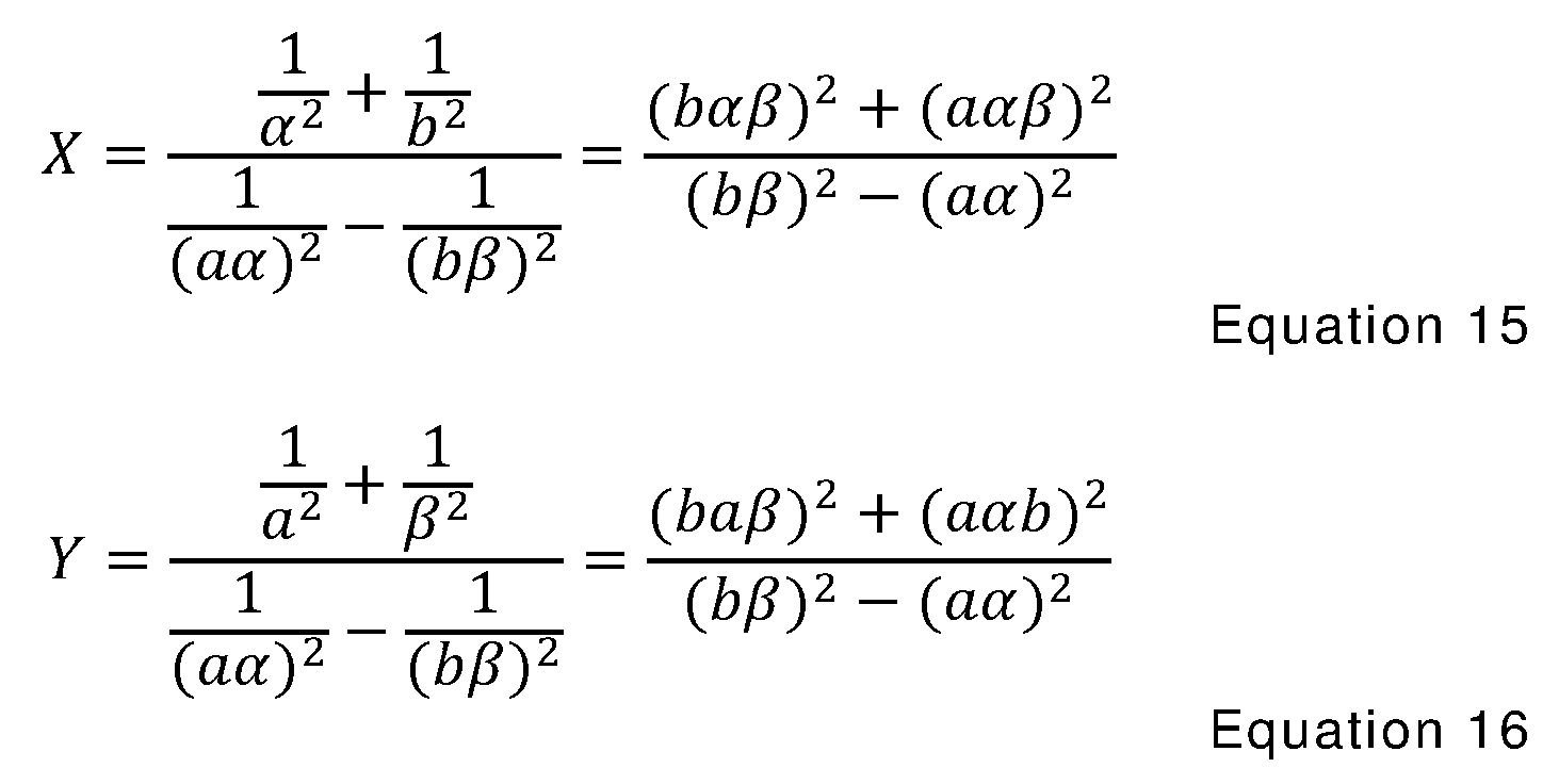
The square roots of X, Y provide the x, y coordinates corresponding to the location 30 of the shooter.
However, in Fig. 1 , there are four quadrants (i.e., upper left, upper right, lower left and lower right) about the origin 15 of the microphone array 12. The x, y coordinates discussed above are ambiguous to sign and the processing circuitry is configured to perform additional processing to identify the specific one of the quadrants containing the xy co-ordinates of location 30 of the firearm discharge using the first and second time differences.
In one embodiment, the signs of the time differences
 of the two pairs of microphones are used to determine the specific quadrant that includes the location of the shooter 30 in accordance with Table A. In the example of Table A with respect to Fig. 1 , quadrant I is the upper right portion of area 1 8, quadrant I I is the upper left, quadrant I I I is the lower left, and quadrant IV is the lower right.

TABLE A
For example, if the time difference Ath of the first pair of microphones 14, 16 is positive and the time difference of the second pair of microphones 15, 1 7 is positive, this indicates that the location 30 of the shooter is in the upper right quadrant of the area being monitored.
Accordingly, in one embodiment, the firearm discharge location system uses data samples corresponding to acoustic signals received from a microphone array to identify the location of the firearm discharge in x, y co-ordinates in one of a plurality of different quadrants.
Referring to Fig. 3, another microphone array 1 2a is shown according to an additional embodiment. The microphones 14, 1 5, 16, 1 7 of array 1 2a are positioned at the corners of the area 1 8a being monitored in the shape of a square in the illustrated configuration.
The location 30 of a firearm discharge 30 is determined using plural intersecting hyperbolas in one embodiment. The location 30 along hyperbola 36 is determined by processing data samples from microphones 14, 1 6 using a time difference tu - ti6 corresponding to the time for the acoustic signals from the firearm discharge to arrive at microphones 14, 1 6 from location 30. The location 30 along hyperbola 38 is determined by processing data samples from microphones 15, 17 using a time difference t2 - t4 corresponding to the time for the acoustic signals from the firearm discharge to arrive at microphones 15, 17 from location 30.
Referring to Fig. 4, a quad microphone array 12 having four microphones 14-17 arranged in a cross is shown according to one embodiment. A plurality of wired or wireless connections 13
commu nicate signals between microphones 14-17 and a hub 40. A bus 42 further communicates the signals between ADCs 20 and clocks 22 and hub 40.
It is noted that sensitivity of a pair of dual independently- synchronized microphones (i.e., quad microphone array) arranged in a cross falls to a minimum on two lines at forty-five degrees relative to the horizontal and vertical axes of the array 12. In one embodiment, sensitivity may be improved by also using another quad array including two pairs of dual independently-synchronized microphones as discussed immediately below.
Referring to Fig. 5, an octagonal microphone array 12b including two quad arrays is shown according to one embodiment. A first quad array includes microphones 14-17 and a second quad array includes microphones 50-53.
Microphones 50, 52 form a third synchronized pair and microphones 51 , 53 form a fourth synchronized pair of the second quad array and the four pairs of microphones are synchronized independently (or asynchronously) of each other for data capture operations, for example using four independent clocks in one embodiment. The first quad array includes a first pair of microphones 14, 16 and a second pair of microphones 15, 17 as discussed above. The second quad array includes a first pair of microphones 50, 52 and a second pair of microphones 51 , 53.
The quad arrays are co-centered and are offset with respect to one another by forty-five degrees in the illustrated example. In addition, the four pairs of microphones implement data captu re or sampling operations independently or asynchronously with respect to one another in one embodiment. In other embodiments, the quad arrays are not co-centered and/or may be offset with respect to each other by other non-zero angles in other embodiments.
A plurality of wired or wireless connections 23 commu nicate signals from the microphones 14-17, 50-53 to a hub 40a. A bus 42a commu nicates signals for the first quad array between the hub 40a and the ADCs 20 and clocks 22 shown on the left and a bus 42b
commu nicates signals for the second quad array between the hub 40a and the ADCs 20 and clocks 22 shown on the right.
In one embodiment, the processing circuitry receives and processes data samples of the signals generated by the microphones 14-1 7, 50-53 to determine the location of a firearm discharge. In one embodiment, the system 10 separately processes the data samples from each quad array as discussed above providing two locations of a firearm discharge. In particular, in addition to using the outputs of the first quad array to identify a first location of the firearm discharge, the system is further configu red to use the outputs of the third and fourth pairs of the microphones to identify a second location of the firearm discharge using data from the second quad array. Thereafter, the processing circuitry is configured to combine (e.g., average) the first and second locations resulting from the data samples of each respective first and second quad array to provide a third final location of the firearm discharge in one embodiment.
Addition of another array co-centered and oriented orthogonally to the plane of the aforementioned quad or octagonal arrays enables determination of the location of a firearm discharge in three dimensions.
The embodiments discussed above are with respect to co centered, orthogonally oriented synchronized pairs of microphones (i.e., the axes between the microphones of the respective pairs are orthogonal to one another). In other embodiments, such as the examples shown in Figs. 6 and 7, the axes of the independent pairs of synchronized microphones are non-parallel with respect to one another but not necessarily orthogonal. In addition, the synchronized pairs of microphones are not co-centered in some embodiments as shown in Figs. 6 and 7. The axes of the independent pairs of synchronized microphones intersect and divide the area to be monitored into four distinct half planes in the illustrated example embodiments.
Referring to Fig. 6, a quad array including two independent pairs 60 of synchronized microphones that are not parallel with respect to one another are shown. Referring to Fig. 7, a first quad array of the illustrated octagonal array includes two independent pairs 62 of
synchronized microphones that are not parallel with respect to one another. A second quad array includes two independent pairs 64 of synchronized microphones that are not parallel with respect to one another. The outputs of the microphones of the embodiments of Figs. 6 and 7 may be processed as discussed above with respect to the orthogonal microphone arrays in one embodiment. Different pairs of the microphones illustrated in Fig. 7 that intersect one another may be selected to form the quad arrays in other embodiments.
In one embodiment, two independent pairs of synchronously triggered microphones generated signals that were useable to detect a shooter 200m away with an accuracy of 99.7%, and a position accuracy of +/- 1 m. Using four pairs of independently synchronized pairs of microphones, it is possible to estimate xy co-ordinates of the shooter within a 400m by 400m-grid to within 0.2m with a probability of actually being correct of 68%, 0.4m with a probability of actually being correct of 95%, and 0.6m with a probability of actually being correct of 99.7%. A location of firearm discharge may be determined to within ±0.1 m accuracy using pairs of microphones that are independently synchronized if arrival times of the acoustic wave from the firearm discharge are measured with at least ±1 5ps accu racy.
According to some embodiments discussed herein, different pairs of microphones of a microphone array are synchronized independent of each other. These embodiments avoid the complexities inherent with the utilization of a master clock to synchronize all of the microphones of the microphone array. In addition, these embodiments provide increased reliability compared with arrangements which utilize a master clock due to their reduced complexity.
In addition, some of the disclosed embodiments permit the timing references for the different pairs of microphones to drift relative to each other in a random or systematic way as time progresses while still providing accu rate results.
Some embodiments of the disclosure described herein may be implemented in portable or permanent installations depending upon the area to be monitored. The disclosed systems and methods extend
abilities to locate shooters as well as perform other operations including triggering of ancillary surveillance equipment, and inform first responders to quickly arrive at specific locations resulting in reduced casualties du ring these events.
Systems and methods discussed herein supplement electronic surveillance and security systems to provide situational awareness and to provide monitoring of “soft targets” such as schools, u niversities, airports, train stations, large stadiu m concerts, sporting events, shopping malls, county fairs, construction sites, parking garages, etc. Furthermore, the systems and methods disclosed herein enable quick location information to be determined regarding threats posed by an active shooter to critical infrastructures such as nuclear power generating facilities, military bases, electric substations, etc.
In compliance with the statute, the invention has been described in language more or less specific as to structu ral and methodical featu res. It is to be understood, however, that the invention is not limited to the specific featu res shown and described, since the means herein disclosed comprise preferred forms of putting the invention into effect. The invention is, therefore, claimed in any of its forms or modifications within the proper scope of the appended aspects appropriately interpreted in accordance with the doctrine of equivalents.
Further, aspects herein have been presented for guidance in construction and/or operation of illustrative embodiments of the disclosure. Applicant(s) hereof consider these described illustrative embodiments to also include, disclose and describe further inventive aspects in addition to those explicitly disclosed. For example, the additional inventive aspects may include less, more and/or alternative featu res than those described in the illustrative embodiments. In more specific examples, Applicants consider the disclosu re to include, disclose and describe methods which include less, more and/or alternative steps than those methods explicitly disclosed as well as apparatus which includes less, more and/or alternative structure than the explicitly disclosed structure.
Claims
1 . A firearm discharge location system comprising :
a plurality of microphones spaced from one another;
timing circuitry configured to generate a plurality of asynchronous timing references;
wherein data capture operations with respect to the microphones of a first pair are synchronized with one another using a first of the timing references and data capture operations with respect to the microphones of a second pair are synchronized with one another using a second of the timing references; and
processing circuitry configu red to use outputs of the first and second pairs of the microphones to identify a location of a firearm discharge.
2. The system of claim 1 wherein the microphones are arranged in in a microphone array having two dimensions.
3. The system of claim 1 wherein the processing circuitry is configu red to determine a first time difference corresponding to the reception of an acoustic signal of the firearm discharge by the microphones of the first pair at different moments in time, to determine a second time difference corresponding to the reception of the acoustic signal of the firearm discharge by the microphones of the second pair at different moments in time, and to use the first and second time differences to identify the location of the firearm discharge.
4. The system of claim 3 fu rther comprising a plurality of analog-to-digital converters configured to sample analog signals received from respective ones of the microphones and to generate a plurality of data samples to implement the data captu re operations, and wherein the processing circuitry is configured to associate a plurality of time stamps with the data samples that exceed a threshold indicative
of a certain level of acoustic energy, and use the time stamps to determine the first and second time differences.
5. The system of claim 4 further comprising a comparator coupled with the processing circuitry, wherein the comparator is configu red to compare the outputs of the microphones with respect to a threshold, and wherein the processing circuitry is configured to associate a plurality of time stamps with the outputs as a result of respective ones of the outputs exceeding the threshold, and use the time stamps to identify the location of the firearm discharge.
6. The system of claim 3 wherein the firearm discharge location system is configured to monitor for the presence of the firearm discharge within an area comprising a plurality of quadrants, and the processing circuitry is configured to identify one of the quadrants containing the location of the firearm discharge using the first and second time differences.
7. The system of claim 1 wherein the firearm discharge location system is configured to monitor for the presence of the firearm discharge within a square area, and the microphones are located at midpoints of the sides of the square area.
8. The system of claim 1 wherein the microphones of the first pair are located at opposite first and second sides of the square area and the microphones of the second pair are located at opposite third and fou rth sides of the square area.
9. The system of claim 1 wherein the firearm discharge location system is configured to monitor for the presence of the firearm discharge within a square area, and at least some of the microphones are located at corners of the square area.
10. The system of claim 1 wherein the microphones are located in a center of an area to be monitored.
1 1 . The system of claim 1 wherein the timing circuitry comprises first and second clocks configured to generate the timing references comprising a plu rality of independent clock signals.
1 2. The system of claim 1 wherein an axis of the microphones of the first pair and an axis of the microphones of the second pair are non-parallel.
1 3. The system of claim 1 wherein an axis of the microphones of the first pair is orthogonal with respect to an axis of the microphones of the second pair.
14. The system of claim 13 wherein the first and second pairs of the microphones are co-centered.
1 5. The system of claim 1 fu rther comprising a third pair of the microphones and a fourth pair of the microphones, and wherein the processing circuitry is configured use outputs of the microphones of the third and fourth pairs to identify the location of the firearm discharge.
1 6. The system of claim 1 5 wherein data capture operations with respect to the microphones of the third pair are synchronized with one another using a third of the timing references and data capture operations with respect to the microphones of the fourth pair are synchronized with one another using a fourth of the timing references.
1 7. The system of claim 15 wherein the location of the firearm discharge is a first location, wherein the processing circuitry is configu red to process the outputs of the third and fourth pairs of the microphones to identify a second location of the firearm discharge, and wherein the processing circuitry is configured to combine the first and second locations to identify a third location of the firearm discharge.
1 8. The system of claim 15 wherein the first, second, third and fourth pairs of the microphones are co-centered.
1 9. The system of claim 18 wherein the first and second pairs of the microphones form a first microphone array, the third and fourth pairs of the microphones form a second microphone array, and the first and second arrays are offset by a non-zero angle with respect to one another.
20. The system of claim 18 wherein the first and second pairs of the microphones form a first microphone array, the third and fourth pairs of the microphones form a second microphone array, and the first and second arrays are offset by forty-five degrees with respect to one another.
21 . The system of claim 1 fu rther comprising a plurality of analog-to-digital converters configured to digitize analog signals received from respective ones of the microphones to implement the data capture operations, and wherein the data captu re operations of the analog-to-digital converters are controlled by respective ones of the timing references.
Priority Applications (4)
| Application Number | Priority Date | Filing Date | Title |
|---|---|---|---|
| US17/285,276 US11927688B2 (en) | 2019-05-18 | 2020-05-15 | Firearm discharge location systems and methods |
| CA3136276A CA3136276C (en) | 2019-05-18 | 2020-05-15 | GUN DISCHARGE LOCATION SYSTEMS AND METHODS |
| MX2021013173A MX2021013173A (en) | 2019-05-18 | 2020-05-15 | Firearm discharge location systems and methods. |
| US18/419,893 US20240168126A1 (en) | 2019-05-18 | 2024-01-23 | Firearm Discharge Location Systems and Methods |
Applications Claiming Priority (2)
| Application Number | Priority Date | Filing Date | Title |
|---|---|---|---|
| US201962849877P | 2019-05-18 | 2019-05-18 | |
| US62/849,877 | 2019-05-18 |
Related Child Applications (2)
| Application Number | Title | Priority Date | Filing Date |
|---|---|---|---|
| US17/285,276 A-371-Of-International US11927688B2 (en) | 2019-05-18 | 2020-05-15 | Firearm discharge location systems and methods |
| US18/419,893 Continuation US20240168126A1 (en) | 2019-05-18 | 2024-01-23 | Firearm Discharge Location Systems and Methods |
Publications (1)
| Publication Number | Publication Date |
|---|---|
| WO2020236607A1 true WO2020236607A1 (en) | 2020-11-26 |
Family
ID=70978626
Family Applications (1)
| Application Number | Title | Priority Date | Filing Date |
|---|---|---|---|
| PCT/US2020/033167 Ceased WO2020236607A1 (en) | 2019-05-18 | 2020-05-15 | Firearm discharge location systems and methods |
Country Status (4)
| Country | Link |
|---|---|
| US (2) | US11927688B2 (en) |
| CA (1) | CA3136276C (en) |
| MX (1) | MX2021013173A (en) |
| WO (1) | WO2020236607A1 (en) |
Cited By (3)
| Publication number | Priority date | Publication date | Assignee | Title |
|---|---|---|---|---|
| US11927688B2 (en) | 2019-05-18 | 2024-03-12 | Battelle Memorial Institute | Firearm discharge location systems and methods |
| US12105216B2 (en) | 2021-12-10 | 2024-10-01 | Battelle Memorial Institute | Waveform emission location determination systems and associated methods |
| US12541025B2 (en) | 2019-09-03 | 2026-02-03 | Battelle Memorial Institute | Firearm discharge location systems and associated methods |
Citations (3)
| Publication number | Priority date | Publication date | Assignee | Title |
|---|---|---|---|---|
| EP1806952A2 (en) * | 2006-01-06 | 2007-07-11 | Agilent Technologies, Inc. | Acoustic location and acoustic signal enhancement |
| KR20150000441A (en) * | 2013-06-24 | 2015-01-02 | 단국대학교 산학협력단 | Method for location detection using time difference of arrival of acousic signal and apparatus therefor |
| WO2016029469A1 (en) * | 2014-08-29 | 2016-03-03 | SZ DJI Technology Co., Ltd. | An unmanned aerial vehicle (uav) for collecting audio data |
Family Cites Families (42)
| Publication number | Priority date | Publication date | Assignee | Title |
|---|---|---|---|---|
| US6522890B2 (en) | 1995-12-22 | 2003-02-18 | Cambridge Positioning Systems, Ltd. | Location and tracking system |
| US6178141B1 (en) | 1996-11-20 | 2001-01-23 | Gte Internetworking Incorporated | Acoustic counter-sniper system |
| US6888455B2 (en) | 1999-06-07 | 2005-05-03 | Traptec Corporation | Method of detecting firearm shot |
| US6961002B2 (en) | 1999-06-07 | 2005-11-01 | Traptec Corporation | Sonic detection system and method of using the same |
| US6847587B2 (en) | 2002-08-07 | 2005-01-25 | Frank K. Patterson | System and method for identifying and locating an acoustic event |
| US7719428B2 (en) | 2003-01-24 | 2010-05-18 | Shotspotter, Inc. | Systems and methods of communications for weapon detection systems |
| US7750814B2 (en) | 2003-01-24 | 2010-07-06 | Shotspotter, Inc. | Highly portable system for acoustic event detection |
| US7359285B2 (en) | 2005-08-23 | 2008-04-15 | Bbn Technologies Corp. | Systems and methods for determining shooter locations with weak muzzle detection |
| US7126877B2 (en) | 2004-08-24 | 2006-10-24 | Bbn Technologies Corp. | System and method for disambiguating shooter locations |
| US7433266B2 (en) | 2004-09-16 | 2008-10-07 | Vanderbilt University | Acoustic source localization system and applications of the same |
| US7796470B1 (en) | 2006-10-05 | 2010-09-14 | Shotspotter, Inc. | Acoustic detection of weapons near transportation centers |
| US7474589B2 (en) | 2006-10-10 | 2009-01-06 | Shotspotter, Inc. | Acoustic location of gunshots using combined angle of arrival and time of arrival measurements |
| US8325563B2 (en) * | 2007-05-24 | 2012-12-04 | Shotspotter, Inc. | Systems and methods of locating weapon fire incidents using measurements/data from acoustic, optical, seismic, and/or other sensors |
| BRPI0823111A2 (en) | 2008-09-30 | 2015-06-16 | Shotspotter Inc | Systems and methods including aspects of audio transfer and / or noise incident location system. |
| US20130192451A1 (en) | 2011-06-20 | 2013-08-01 | Steven Gregory Scott | Anti-sniper targeting and detection system |
| US9488442B2 (en) | 2011-06-20 | 2016-11-08 | Real Time Companies, LLC | Anti-sniper targeting and detection system |
| US20130206901A1 (en) | 2012-02-15 | 2013-08-15 | Carl R. Herman | Small arms classification/identification using burst analysis |
| US20140269199A1 (en) | 2013-03-14 | 2014-09-18 | Supervene LLC | System and method for detecting and responding to indoor shooters |
| KR20140126788A (en) * | 2013-04-22 | 2014-11-03 | 한국전자통신연구원 | Position estimation system using an audio-embedded time-synchronization signal and position estimation method using thereof |
| US10819959B2 (en) | 2014-11-05 | 2020-10-27 | Jason Christopher Palazzolo | Firearm environmental recording apparatus and system |
| US10089845B2 (en) | 2015-03-05 | 2018-10-02 | Battelle Memorial Institute | System and method of detecting and analyzing a threat in a confined environment |
| US10290195B2 (en) | 2015-03-05 | 2019-05-14 | Battelle Memorial Institute | System and method of detecting and analyzing a threat in a confined environment |
| US9910128B2 (en) | 2015-03-26 | 2018-03-06 | Databuoy Corporation | Acoustic source localization in confined spaces |
| US9689966B2 (en) | 2015-04-07 | 2017-06-27 | The United States Of America As Represented By The Secretary Of The Army | System and method for identifying location of gunfire from a moving object |
| US20180356492A1 (en) | 2015-06-16 | 2018-12-13 | Michael Hamilton | Vision based location estimation system |
| US9891306B2 (en) | 2015-07-02 | 2018-02-13 | Raytheon Company | Geolocating a remote emitter |
| US20180306890A1 (en) * | 2015-10-30 | 2018-10-25 | Hornet Industries, Llc | System and method to locate and identify sound sources in a noisy environment |
| US10871548B2 (en) | 2015-12-04 | 2020-12-22 | Fazecast, Inc. | Systems and methods for transient acoustic event detection, classification, and localization |
| US9900738B2 (en) | 2015-12-22 | 2018-02-20 | Massachusetts Institute Of Technology | System and method of automatically identifying mobile communication devices within the vicinity of a gunshot |
| US20170234966A1 (en) | 2016-02-17 | 2017-08-17 | Qualcomm Incorporated | Device for uav detection and identification |
| CN105717489A (en) | 2016-03-11 | 2016-06-29 | 歌尔声学股份有限公司 | Following method and device of unmanned aerial vehicle and wearable equipment |
| US10337835B2 (en) | 2016-05-11 | 2019-07-02 | Rivada Research LLC | Method and system for using enhanced location-based information to guide munitions |
| US11112418B1 (en) | 2016-07-29 | 2021-09-07 | Labrador Diagnostics Llc | Systems and methods for multi-analysis |
| US10887541B2 (en) * | 2017-01-26 | 2021-01-05 | Jordan Martin | Gun fire location apparatus, system and methods of operating the same |
| US11125521B2 (en) * | 2017-01-27 | 2021-09-21 | Armaments Research Company, Inc. | Weapon usage monitoring system for initiating notifications and commands based on dashboard actions |
| US10598756B2 (en) | 2017-11-30 | 2020-03-24 | Mesa Engineering, Inc. | System and method for determining the source location of a firearm discharge |
| US10928244B2 (en) | 2018-01-10 | 2021-02-23 | Hdwb, Llc | Detection of discharge of projectile from firearm |
| CN111213365A (en) | 2018-08-17 | 2020-05-29 | 深圳市大疆创新科技有限公司 | Shooting control method and controller |
| US11927688B2 (en) * | 2019-05-18 | 2024-03-12 | Battelle Memorial Institute | Firearm discharge location systems and methods |
| CA3151828A1 (en) | 2019-09-03 | 2021-03-11 | Battelle Memorial Institute | Firearm discharge location systems and associated methods |
| US11955136B2 (en) | 2020-03-27 | 2024-04-09 | Arizona Board Of Regents On Behalf Of Arizona State University | Systems and methods for gunshot detection |
| US12105216B2 (en) * | 2021-12-10 | 2024-10-01 | Battelle Memorial Institute | Waveform emission location determination systems and associated methods |
-
2020
- 2020-05-15 US US17/285,276 patent/US11927688B2/en active Active
- 2020-05-15 MX MX2021013173A patent/MX2021013173A/en unknown
- 2020-05-15 WO PCT/US2020/033167 patent/WO2020236607A1/en not_active Ceased
- 2020-05-15 CA CA3136276A patent/CA3136276C/en active Active
-
2024
- 2024-01-23 US US18/419,893 patent/US20240168126A1/en active Pending
Patent Citations (3)
| Publication number | Priority date | Publication date | Assignee | Title |
|---|---|---|---|---|
| EP1806952A2 (en) * | 2006-01-06 | 2007-07-11 | Agilent Technologies, Inc. | Acoustic location and acoustic signal enhancement |
| KR20150000441A (en) * | 2013-06-24 | 2015-01-02 | 단국대학교 산학협력단 | Method for location detection using time difference of arrival of acousic signal and apparatus therefor |
| WO2016029469A1 (en) * | 2014-08-29 | 2016-03-03 | SZ DJI Technology Co., Ltd. | An unmanned aerial vehicle (uav) for collecting audio data |
Cited By (3)
| Publication number | Priority date | Publication date | Assignee | Title |
|---|---|---|---|---|
| US11927688B2 (en) | 2019-05-18 | 2024-03-12 | Battelle Memorial Institute | Firearm discharge location systems and methods |
| US12541025B2 (en) | 2019-09-03 | 2026-02-03 | Battelle Memorial Institute | Firearm discharge location systems and associated methods |
| US12105216B2 (en) | 2021-12-10 | 2024-10-01 | Battelle Memorial Institute | Waveform emission location determination systems and associated methods |
Also Published As
| Publication number | Publication date |
|---|---|
| US11927688B2 (en) | 2024-03-12 |
| US20240168126A1 (en) | 2024-05-23 |
| MX2021013173A (en) | 2021-12-10 |
| CA3136276A1 (en) | 2020-11-26 |
| CA3136276C (en) | 2024-07-02 |
| US20210389412A1 (en) | 2021-12-16 |
Similar Documents
| Publication | Publication Date | Title |
|---|---|---|
| US20240168126A1 (en) | Firearm Discharge Location Systems and Methods | |
| US12196870B2 (en) | Device for acoustic source localization | |
| AU2014101039A4 (en) | Projectile target system | |
| US6109614A (en) | Remote sensing apparatus of supersonic projectile | |
| US6720921B2 (en) | Position location and tracking method and system employing low frequency radio signal processing | |
| AU2022430004B2 (en) | Method and System for Active Detection of Door Sealing Performance and Leakage Point Location | |
| US12541025B2 (en) | Firearm discharge location systems and associated methods | |
| SE519089C2 (en) | Systems for sending signals from targets to determine locations and speeds for the targets | |
| Wang et al. | Multipath imaging for NLOS targets behind a T-shaped corridor with single-channel SFCW radar | |
| CN107367201B (en) | A kind of fried drop point sound localization method of a wide range of multiple target shell | |
| US20250347763A1 (en) | Device for Acoustic Source Localization | |
| Karnas et al. | Instrumentation and data analysis process at the new lightning research station in Poland | |
| US20190154791A1 (en) | Three-dimensional acoustic detection and imaging via hexidrant isolation and delay-mixing | |
| Mohammad et al. | Azimuth and elevation factors correction for single station lightning electromagnetic field sensor | |
| CN113325465B (en) | Method and system for quickly positioning ground intrusion target | |
| Retscher et al. | Trilateration approaches for indoor Wi-Fi positioning | |
| Klincewicz | Demonstrator of the SDR-based multistatic system for localizing different sources of emissions | |
| US20250341605A1 (en) | Device for Acoustic Source Localization | |
| CN104198987A (en) | Projection strategy based distributed multi-sensor multi-target passive locating method | |
| RU2549919C1 (en) | Method for determining bearing of sound source at arrangement of acoustic antenna of acoustic radar in inclined sections of ground surface | |
| Băluţă et al. | Determining the coordinates of a hostile gunfire by using the sound ranging method | |
| RU2674265C1 (en) | Correlation and basic system of location of fixed sources of radio emission with use of unmanned aircraft | |
| RU2494343C1 (en) | Device for detection and measurement of azimuth angle of light-emitting pulse objects | |
| Manana et al. | Investigation of extensive air showers by means of the network of the cosmic rays stations in Georgia | |
| RU2670731C2 (en) | Method for determining supersonic projectile flight trajectory |
Legal Events
| Date | Code | Title | Description |
|---|---|---|---|
| 121 | Ep: the epo has been informed by wipo that ep was designated in this application |
Ref document number: 20730860 Country of ref document: EP Kind code of ref document: A1 |
|
| ENP | Entry into the national phase |
Ref document number: 3136276 Country of ref document: CA |
|
| NENP | Non-entry into the national phase |
Ref country code: DE |
|
| 122 | Ep: pct application non-entry in european phase |
Ref document number: 20730860 Country of ref document: EP Kind code of ref document: A1 |