WO2020235569A1 - Connection of concrete-filled steel tube column and reinforced concrete slab - Google Patents
Connection of concrete-filled steel tube column and reinforced concrete slab Download PDFInfo
- Publication number
- WO2020235569A1 WO2020235569A1 PCT/JP2020/019816 JP2020019816W WO2020235569A1 WO 2020235569 A1 WO2020235569 A1 WO 2020235569A1 JP 2020019816 W JP2020019816 W JP 2020019816W WO 2020235569 A1 WO2020235569 A1 WO 2020235569A1
- Authority
- WO
- WIPO (PCT)
- Prior art keywords
- steel tube
- tube column
- ribs
- slab
- connection
- Prior art date
- Legal status (The legal status is an assumption and is not a legal conclusion. Google has not performed a legal analysis and makes no representation as to the accuracy of the status listed.)
- Ceased
Links
Images






Classifications
-
- E—FIXED CONSTRUCTIONS
- E04—BUILDING
- E04B—GENERAL BUILDING CONSTRUCTIONS; WALLS, e.g. PARTITIONS; ROOFS; FLOORS; CEILINGS; INSULATION OR OTHER PROTECTION OF BUILDINGS
- E04B1/00—Constructions in general; Structures which are not restricted either to walls, e.g. partitions, or floors or ceilings or roofs
- E04B1/16—Structures made from masses, e.g. of concrete, cast or similarly formed in situ with or without making use of additional elements, such as permanent forms, substructures to be coated with load-bearing material
- E04B1/165—Structures made from masses, e.g. of concrete, cast or similarly formed in situ with or without making use of additional elements, such as permanent forms, substructures to be coated with load-bearing material with elongated load-supporting parts, cast in situ
-
- E—FIXED CONSTRUCTIONS
- E04—BUILDING
- E04B—GENERAL BUILDING CONSTRUCTIONS; WALLS, e.g. PARTITIONS; ROOFS; FLOORS; CEILINGS; INSULATION OR OTHER PROTECTION OF BUILDINGS
- E04B5/00—Floors; Floor construction with regard to insulation; Connections specially adapted therefor
- E04B5/43—Floor structures of extraordinary design; Features relating to the elastic stability; Floor structures specially designed for resting on columns only, e.g. mushroom floors
-
- E—FIXED CONSTRUCTIONS
- E04—BUILDING
- E04C—STRUCTURAL ELEMENTS; BUILDING MATERIALS
- E04C5/00—Reinforcing elements, e.g. for concrete; Auxiliary elements therefor
- E04C5/01—Reinforcing elements of metal, e.g. with non-structural coatings
- E04C5/06—Reinforcing elements of metal, e.g. with non-structural coatings of high bending resistance, i.e. of essentially three-dimensional [3D] extent, e.g. lattice girders
- E04C5/0645—Shear reinforcements, e.g. shearheads for floor slabs
Definitions
- CFT columns concrete-filled steel tube columns
- RC slabs reinforced concrete slabs
- the disclosure relates to connections of RC slabs as flat slabs and CFT columns penetrating through the slabs.
- Flat slab structures have been used in architectural structures such as office/residential buildings or warehouses with many external walls, basements, and the like, making use of their advantages in formwork saving, floor height reduction, and so on.
- Such flat slab structures are generally formed by reinforced concrete columns (RC columns) and RC slabs.
- RC columns reinforced concrete columns
- This arrangement requires a structural component called a capital part, which is used for transferring vertical loads on an RC slab to the columns, causing the problems of reduction in ceiling height around the columns and deterioration of construction workability.
- JPH8109695A (PTL 1) describes a connection comprising: a steel tube column 61; an RC slab 64; four ribs 63 welded to the steel tube column 61 through slits cut in the steel tube column 61, each of the ribs 63 having two parts, one part being located inside the steel tube column 61 and the other part being located inside the RC slab 64; and a horizontal bearing steel plate 62 welded to the steel tube column 61 and having the RC slab 64 mounted thereon.
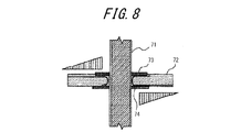
- JP2000160685A (PTL 2) describes a connection capable of resisting horizontal loads comprising: a CFT column 71; an RC slab 72; and bearing steel plates 73, 74 joined to the CFT column 71 at positions corresponding to the bottom and top surfaces of the RC slab 72, respectively, so as to surround the CFT column 71.
- JP2008088639A (PTL 3) describes a connection capable of resisting vertical loads on an RC slab, the connection comprising: a plurality of perforated dowels 82 fixed to the outer circumferential surface of a steel tube column 81, at positions between top and bottom reinforcements 86, 87 constituting slab reinforcements of an RC slab 84, each of the perforated dowels 82 having a largest plane coinciding with a vertical plane; and auxiliary reinforcing bars 83 provided independently from the slab reinforcements 86, 87 and threaded through the perforations 82a in the dowels.
- PTL 1 JPH8109695A
- PTL 2 JP2000160685A
- PTL 3 JP2008088639A
- connection described in PTL 1 has ribs interfering with slab reinforcements, which prevents sufficient fixation of slab reinforcements at the joining parts.
- extent to which ribs protrude into a steel tube column is so small that vertical loads imposed on the RC slab cannot be sufficiently transferred to the infilled concrete.
- connection described in PTL 2 is a structure that is designed focusing on ways to resist horizontal loads, and is thus not able to sufficiently transfer vertical loads imposed on an RC slab to the infilled concrete.
- connection described in PTL 3 is designed to transfer vertical loads imposed on an RC slab to the infilled concrete in a steel tube column merely by the bond of the steel tube column to the infilled concrete alone, and is thus not able to sufficiently transfer vertical loads imposed on RC slabs to the infilled concrete. Additionally, with the connection described in PTL 3, when large vertical loads are applied to an RC slab and when the plate thickness of the steel pipe or tube is small, plasticization can locally develop in the steel tube column, leading to premature failure of the column.
- a connection of a steel tube column infilled with concrete and an RC slab wherein a plurality of ribs are connected to the steel tube column through slits provided in the steel tube column, such that the largest planes of the ribs coincide with a substantially vertical plane, each of the ribs having two parts, one part being located inside the steel tube column and the other part being located outside the steel tube column, a bearing steel plate is connected to the outer circumferential surface of the steel tube column and to the upper ends of the plurality of ribs, such that the largest plane of the bearing steel plate coincides with a substantially horizontal plane, the RC slab is mounted on the bearing steel plate, and each of the ribs has at least one first through-hole in the one part located inside the steel tube column.
- each of the ribs has a plurality of the first through-holes along a substantially vertical direction.
- connection of a CFT column and an RC slab disclosed herein may resist larger vertical loads imposed on the RC slab.
- FIG. 1 illustrates a connection 100 according to a first one of the disclosed embodiments, (A) is a vertical cross-sectional view and (B) is a horizontal cross-sectional view;
- FIG. 2 is a diagram illustrating the positions at which slits 14 and second through-holes 16 are provided in the steel tube column 10 in the connection 100 presented in FIG. 1;
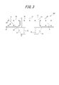
- FIG. 3 is a diagram illustrating a failure mode of a slab 20 when placed under punching shear force;
- FIG. 4 illustrates a connection 200 according to a second embodiment, (A) is a vertical cross-sectional view and (B) is a horizontal cross-sectional view;
- FIG. 5 is a horizontal cross-sectional view of a connection 300 according to a third embodiment;
- FIG. 6 is a top view of a connection described in PTL 1;
- FIG. 7 is an A-A cross-sectional view of FIG. 6;
- FIG. 8 is a vertical cross-sectional view of a connection described in PTL 2;
- FIG. 9 is a perspective view of the connection described in PTL 2;
- FIG. 10(A) is a top view of a connection described in PTL 3; and
- FIG. 10(B) is an A-A cross-sectional view of FIG. 10(A).
- a connection 100 of a CFT column and an RC slab according to a first embodiment is described below.
- a steel tube column 10 (a steel pipe column) is installed to penetrate through an RC slab 20, which makes it possible to reduce the welding work as well as the time and cost for construction, as compared to the case where the steel tube column is divided into sections.
- the RC slab may be a prestressed concrete slab (PC slab).
- a plurality of (in this embodiment, eight) slits 14 are provided in the steel tube column 10 infilled with concrete 12.
- a rib 30, which will be discussed below, is inserted through each slit 14.
- a plurality of (in this embodiment, twelve) second through-holes 16 are also provided in the steel tube column 10.
- a top reinforcement 24 is threaded through each second through-hole 16, as described later. While the steel tube column 10 is illustrated in FIG. 1 as being a circular steel pipe or tube, it is not so limited and may thus be a square or rectangular steel pipe or tube.
- a plurality of (in this embodiment, eight) ribs 30 are connected to the steel tube column 10 through the respective slits 14 provided in the column, such that the largest planes of the ribs coincide with a substantially vertical plane.
- Each of the ribs 30 has two parts, one part being located inside the steel tube column 10 and the other part being located outside the steel tube column 10. It should be noted that the phrase "the largest planes of the ribs coincide with a substantially vertical plane" is intended to cover the case where the largest planes of the ribs coincide with the vertical plane, as well as the case where the largest planes of the ribs are at an inclination of 5° or less with respect to the vertical plane.
- these ribs 30 extend both inside and outside the steel tube column 10, it is possible to reduce out-of-plane bending of the skin plate of the steel tube column 10 and prevent premature plasticization of the skin plate of the steel tube column 10, compared to installing ribs only outside the steel tube column.
- a bearing steel plate 40 is connected to the outer circumferential surface of the steel tube column 10 and to the upper ends of the plurality of ribs 30, such that the largest plane of the bearing steel plate coincides with a substantially horizontal plane. Then, the RC slab 20 is mounted on the bearing steel plate 40. It should be noted that the phrase "the largest plane of the bearing steel plate coincides with a substantially horizontal plane” is intended to cover the case where the largest plane of the bearing steel plate coincides with the horizontal plane as well as the case where the largest plane of the bearing steel plate is at an inclination of 5° or less with respect to the horizontal plane.
- each rib 30 has first through-holes 32 penetrating through its surface at positions inside the steel tube column 10. Consequently, the area of contact between the ribs 30 and the infilled concrete 12 increases, with the result that vertical loads transferred from the RC slab 20 may be transferred to the infilled concrete 12 in the steel tube column 10, by means of the bond strength between the ribs 30 and the infilled concrete 12 as well as the bearing capacity of the first through-holes 32 and the lower ends of the ribs 30 and the infilled concrete 12.
- the connection 100 may resist larger vertical loads imposed on the RC slab 20.
- the plurality of ribs 30 are arranged below the bearing steel plate 40.
- This configuration easily avoids interference of ribs with slab reinforcements 22 inside the RC slab 20, and has an advantage that the RC slab 20 becomes less prone to corruption.
- a total of eight ribs are arranged in four directions at 90° angles from the steel tube column 10, two ribs for each direction, as viewed in a horizontal plane.
- the number of ribs is not limited to eight and, for example, a total of four ribs (instead of eight ribs) may be arranged in the four directions, one rib for each direction.
- the ribs 30 are made of steel sheets.
- the thickness of each rib 30 is not particularly limited, yet, for example, the lower limit may be 6 mm and, considering the skin plate thickness (up to 28 mm) for a circular steel tube column, the upper limit may be 32 mm. This is not so limited for a square or rectangular steel pipe or tube.
- the shape of each rib 30 is not particularly limited, yet the largest plane of one part of the rib located inside the steel tube column 10 preferably has a rectangular shape, as illustrated in FIG. 1(A). On the other hand, the shape of the principal surface of the other part located outside the steel tube column 10 is preferably triangular so as to minimize the amount of space consumed by the rib.
- Each rib 30 preferably has a maximum vertical length L v that is 70 % to 150 % of the slab thickness.
- the part of each rib 30 located outside the steel tube column 10 preferably has a maximum horizontal length that is 50 % to 200 % of the slab thickness.
- the part of each rib 30 located inside the steel tube column 10 preferably has a horizontal length that is 15 % to 30 % of the diameter of the steel tube column 10, from the perspective of ensuring transfer of vertical loads to the infilled concrete 12.
- each rib 30 preferably has a plurality of first through-holes 32 along a substantially vertical direction. In this embodiment, each rib 30 has three first through-holes 32. This allows more reliable transfer of vertical loads to the infilled concrete 12.
- the phrase "along a substantially vertical direction" is intended to mean a state in which adjacent first through-holes at least partially overlap one another in the vertical direction.
- the bearing steel plate 40 is a ring-shaped steel sheet which extends to surround the steel tube column 10.
- the bearing steel plate 40 is preferably formed by joining two equal parts together by welding or the like.
- no particular limitation is placed on the shape of the bearing steel plate 40, insofar as the bearing steel plate 40 extends immediately above all ribs and is large enough to support the RC slab 20.
- the bearing steel plate 40 preferably has a plate thickness that is approximately 10 % to 20 % of the slab thickness. Embodiments in which the bearing steel plate 40 has different shapes will be discussed later.
- reinforcing bars are arranged inside the RC slab 20 as illustrated in FIGS. 1(A) and 3.
- some of top reinforcements 24, which constitute the slab reinforcements 22 inside the reinforced concrete slab are arranged to penetrate through the steel tube column 10 via second through-holes 16 provided in the steel tube column 10.
- those top reinforcements 24 penetrating through the steel tube column 10 can resist any tension applied to the failure surface A, allowing the RC slab 20 to resist larger punching shear force.
- the above configuration may ensure fixation of the slab reinforcements 22.
- the connecting of the plurality of ribs 30 to the steel tube column 10 and/or the connecting of the bearing steel plate 40 to the outer circumferential surface of the steel tube column 10 and to the upper ends of the plurality of ribs 30 are preferably performed by fillet welding.
- Such connecting operation by fillet welding may reduce the time and cost for construction as compared to performing connecting operation by full penetration welding.
- connection 200 of a CFT column and an RC slab according to a second embodiment is described below.
- the connection 200 according to this embodiment is similar to the connection 100 according to the first embodiment, except that some of bottom reinforcements 26 are also arranged to penetrate through the steel tube column 10 via second through-holes 16 provided in the steel tube column 10.
- This configuration allows the RC slab 20 to resist larger punching shear force. In other words, the above configuration may ensure fixation of the slab reinforcements 22.
- connection 300 of a CFT column and an RC slab according to a third embodiment is described below.
- the connection 300 according to this embodiment is similar to the connection 100 according to the first embodiment, except that it has bearing steel plates 40 with a different shape.
- bearing steel plates 40 are provided, each being arranged immediately above two ribs 30, respectively.
- bearing steel plates are provided only above ribs to reduce the amount of steel material used.
- the bearing steel plates have a substantially rectangular shape, which reduces waste in material processing.
- first to third embodiments are merely representative of the disclosed connection and should not be taken as limiting the scope of the claims.
- Other configurations are also possible, including, for example, a connection obtained by combining at least two of the first to third embodiments as appropriate.
- only some of bottom reinforcements 26 may be arranged to penetrate through the steel tube column 10 via second through-holes 16 provided in the steel tube column 10.
Landscapes
- Engineering & Computer Science (AREA)
- Architecture (AREA)
- Civil Engineering (AREA)
- Structural Engineering (AREA)
- Physics & Mathematics (AREA)
- Electromagnetism (AREA)
- Joining Of Building Structures In Genera (AREA)
Abstract
Disclosed is a connection of a CFT column and an RC slab that can resist larger vertical loads imposed on the RC slab. A connection of a steel tube column 10 infilled with concrete 12 and an RC slab 20 is provided. A plurality of ribs 30 are connected to the steel tube column 10 through slits 14 provided in the steel tube column 10, such that the largest planes of the ribs coincide with a substantially vertical plane. Each of the ribs 30 has two parts, one part being located inside the steel tube column 10 and the other part being located outside the steel tube column 10. A bearing steel plate 40 is connected to the outer circumferential surface of the steel tube column 10 and to the upper ends of the ribs 30, such that the largest plane of the bearing steel plate coincides with a substantially horizontal plane. The RC slab 20 is mounted on the bearing steel plate 40. Each of the ribs 30 has at least one first through-hole 32 in the one part located inside the steel tube column 10.
Description
This disclosure relates to connections of concrete-filled steel tube columns (hereinafter, "CFT columns" ("CFT" is an abbreviation for "Concrete Filled steel Tube")) and reinforced concrete slabs (hereinafter, "RC slabs" or "RC slab"). In particular, the disclosure relates to connections of RC slabs as flat slabs and CFT columns penetrating through the slabs.
Flat slab structures have been used in architectural structures such as office/residential buildings or warehouses with many external walls, basements, and the like, making use of their advantages in formwork saving, floor height reduction, and so on. Such flat slab structures are generally formed by reinforced concrete columns (RC columns) and RC slabs. This arrangement, however, requires a structural component called a capital part, which is used for transferring vertical loads on an RC slab to the columns, causing the problems of reduction in ceiling height around the columns and deterioration of construction workability.
Therefore, as structures that allow omitting capital parts, various connections of CFT columns and RC slabs have been proposed. Referring to FIGs. 6 and 7, JPH8109695A (PTL 1) describes a connection comprising: a steel tube column 61; an RC slab 64; four ribs 63 welded to the steel tube column 61 through slits cut in the steel tube column 61, each of the ribs 63 having two parts, one part being located inside the steel tube column 61 and the other part being located inside the RC slab 64; and a horizontal bearing steel plate 62 welded to the steel tube column 61 and having the RC slab 64 mounted thereon.
Referring to FIGs. 8 and 9, JP2000160685A (PTL 2) describes a connection capable of resisting horizontal loads comprising: a CFT column 71; an RC slab 72; and bearing steel plates 73, 74 joined to the CFT column 71 at positions corresponding to the bottom and top surfaces of the RC slab 72, respectively, so as to surround the CFT column 71.
Referring to FIGs. 10(A) and 10(B), JP2008088639A (PTL 3) describes a connection capable of resisting vertical loads on an RC slab, the connection comprising: a plurality of perforated dowels 82 fixed to the outer circumferential surface of a steel tube column 81, at positions between top and bottom reinforcements 86, 87 constituting slab reinforcements of an RC slab 84, each of the perforated dowels 82 having a largest plane coinciding with a vertical plane; and auxiliary reinforcing bars 83 provided independently from the slab reinforcements 86, 87 and threaded through the perforations 82a in the dowels.
PTL 1: JPH8109695A
PTL 2: JP2000160685A
PTL 3: JP2008088639A
PTL 2: JP2000160685A
PTL 3: JP2008088639A
However, the techniques described in PTL 1 to PTL 3 all require further improvement in terms of resistance to vertical loads on RC slabs.
Specifically, the connection described in PTL 1 has ribs interfering with slab reinforcements, which prevents sufficient fixation of slab reinforcements at the joining parts. In addition, the extent to which ribs protrude into a steel tube column is so small that vertical loads imposed on the RC slab cannot be sufficiently transferred to the infilled concrete.
The connection described in PTL 2 is a structure that is designed focusing on ways to resist horizontal loads, and is thus not able to sufficiently transfer vertical loads imposed on an RC slab to the infilled concrete.
The connection described in PTL 3 is designed to transfer vertical loads imposed on an RC slab to the infilled concrete in a steel tube column merely by the bond of the steel tube column to the infilled concrete alone, and is thus not able to sufficiently transfer vertical loads imposed on RC slabs to the infilled concrete. Additionally, with the connection described in PTL 3, when large vertical loads are applied to an RC slab and when the plate thickness of the steel pipe or tube is small, plasticization can locally develop in the steel tube column, leading to premature failure of the column.
It could thus be helpful to provide such a connection of a CFT column and an RC slab that can resist larger vertical loads imposed on the RC slab.
We thus provide:
(1) A connection of a steel tube column infilled with concrete and an RC slab, wherein
a plurality of ribs are connected to the steel tube column through slits provided in the steel tube column, such that the largest planes of the ribs coincide with a substantially vertical plane, each of the ribs having two parts, one part being located inside the steel tube column and the other part being located outside the steel tube column,
a bearing steel plate is connected to the outer circumferential surface of the steel tube column and to the upper ends of the plurality of ribs, such that the largest plane of the bearing steel plate coincides with a substantially horizontal plane,
the RC slab is mounted on the bearing steel plate, and
each of the ribs has at least one first through-hole in the one part located inside the steel tube column.
(1) A connection of a steel tube column infilled with concrete and an RC slab, wherein
a plurality of ribs are connected to the steel tube column through slits provided in the steel tube column, such that the largest planes of the ribs coincide with a substantially vertical plane, each of the ribs having two parts, one part being located inside the steel tube column and the other part being located outside the steel tube column,
a bearing steel plate is connected to the outer circumferential surface of the steel tube column and to the upper ends of the plurality of ribs, such that the largest plane of the bearing steel plate coincides with a substantially horizontal plane,
the RC slab is mounted on the bearing steel plate, and
each of the ribs has at least one first through-hole in the one part located inside the steel tube column.
(2) The connection according to aspect (1), wherein each of the ribs has a plurality of the first through-holes along a substantially vertical direction.
(3) The connection according to aspect (1) or (2), wherein some of top reinforcements and/or some of bottom reinforcements provided inside the RC slab are arranged to penetrate through the steel tube column via second through-holes provided in the steel tube column.
(4) The connection according to any one of aspects (1) to (3), wherein the connecting of the plurality of ribs to the steel tube column and/or the connecting of the bearing steel plate to the outer circumferential surface of the steel tube column and to the upper ends of the plurality of ribs are performed by fillet welding.
The connection of a CFT column and an RC slab disclosed herein may resist larger vertical loads imposed on the RC slab.
In the accompanying drawings:
FIG. 1 illustrates a connection 100 according to a first one of the disclosed embodiments, (A) is a vertical cross-sectional view and (B) is a horizontal cross-sectional view;
FIG. 2 is a diagram illustrating the positions at which slits 14 and second through-holes 16 are provided in the steel tube column 10 in the connection 100 presented in FIG. 1;
FIG. 3 is a diagram illustrating a failure mode of a slab 20 when placed under punching shear force;
FIG. 4 illustrates a connection 200 according to a second embodiment, (A) is a vertical cross-sectional view and (B) is a horizontal cross-sectional view;
FIG. 5 is a horizontal cross-sectional view of a connection 300 according to a third embodiment;
FIG. 6 is a top view of a connection described in PTL 1;
FIG. 7 is an A-A cross-sectional view of FIG. 6;
FIG. 8 is a vertical cross-sectional view of a connection described in PTL 2;
FIG. 9 is a perspective view of the connection described in PTL 2;
FIG. 10(A) is a top view of a connection described in PTL 3; andFIG. 10(B) is an A-A cross-sectional view of FIG. 10(A).
Embodiments of the connection disclosed herein will be described in detail below with reference to the drawings. It is noted that similar members are referred to by the same reference numerals throughout the embodiments.
(First Embodiment)
With reference to FIGS. 1 to 3, aconnection 100 of a CFT column and an RC slab according to a first embodiment is described below. In this embodiment, a steel tube column 10 (a steel pipe column) is installed to penetrate through an RC slab 20, which makes it possible to reduce the welding work as well as the time and cost for construction, as compared to the case where the steel tube column is divided into sections. The RC slab may be a prestressed concrete slab (PC slab).
With reference to FIGS. 1 to 3, a
That is, with reference to FIGS. 1 and 2, a plurality of (in this embodiment, eight) slits 14 are provided in the steel tube column 10 infilled with concrete 12. A rib 30, which will be discussed below, is inserted through each slit 14. A plurality of (in this embodiment, twelve) second through-holes 16 are also provided in the steel tube column 10. A top reinforcement 24 is threaded through each second through-hole 16, as described later. While the steel tube column 10 is illustrated in FIG. 1 as being a circular steel pipe or tube, it is not so limited and may thus be a square or rectangular steel pipe or tube.
Referring first to FIG. 1, a plurality of (in this embodiment, eight) ribs 30 are connected to the steel tube column 10 through the respective slits 14 provided in the column, such that the largest planes of the ribs coincide with a substantially vertical plane. Each of the ribs 30 has two parts, one part being located inside the steel tube column 10 and the other part being located outside the steel tube column 10. It should be noted that the phrase "the largest planes of the ribs coincide with a substantially vertical plane" is intended to cover the case where the largest planes of the ribs coincide with the vertical plane, as well as the case where the largest planes of the ribs are at an inclination of 5° or less with respect to the vertical plane. Since these ribs 30 extend both inside and outside the steel tube column 10, it is possible to reduce out-of-plane bending of the skin plate of the steel tube column 10 and prevent premature plasticization of the skin plate of the steel tube column 10, compared to installing ribs only outside the steel tube column.
In addition, a bearing steel plate 40 is connected to the outer circumferential surface of the steel tube column 10 and to the upper ends of the plurality of ribs 30, such that the largest plane of the bearing steel plate coincides with a substantially horizontal plane. Then, the RC slab 20 is mounted on the bearing steel plate 40. It should be noted that the phrase "the largest plane of the bearing steel plate coincides with a substantially horizontal plane" is intended to cover the case where the largest plane of the bearing steel plate coincides with the horizontal plane as well as the case where the largest plane of the bearing steel plate is at an inclination of 5° or less with respect to the horizontal plane.
In this embodiment, each rib 30 has first through-holes 32 penetrating through its surface at positions inside the steel tube column 10. Consequently, the area of contact between the ribs 30 and the infilled concrete 12 increases, with the result that vertical loads transferred from the RC slab 20 may be transferred to the infilled concrete 12 in the steel tube column 10, by means of the bond strength between the ribs 30 and the infilled concrete 12 as well as the bearing capacity of the first through-holes 32 and the lower ends of the ribs 30 and the infilled concrete 12. Thus, the connection 100 according to this embodiment may resist larger vertical loads imposed on the RC slab 20.
In this embodiment, the plurality of ribs 30 are arranged below the bearing steel plate 40. This configuration easily avoids interference of ribs with slab reinforcements 22 inside the RC slab 20, and has an advantage that the RC slab 20 becomes less prone to corruption. Additionally, in this embodiment, as illustrated in FIG. 1(B), a total of eight ribs are arranged in four directions at 90° angles from the steel tube column 10, two ribs for each direction, as viewed in a horizontal plane. The number of ribs is not limited to eight and, for example, a total of four ribs (instead of eight ribs) may be arranged in the four directions, one rib for each direction.
The ribs 30 are made of steel sheets. The thickness of each rib 30 is not particularly limited, yet, for example, the lower limit may be 6 mm and, considering the skin plate thickness (up to 28 mm) for a circular steel tube column, the upper limit may be 32 mm. This is not so limited for a square or rectangular steel pipe or tube. The shape of each rib 30 is not particularly limited, yet the largest plane of one part of the rib located inside the steel tube column 10 preferably has a rectangular shape, as illustrated in FIG. 1(A). On the other hand, the shape of the principal surface of the other part located outside the steel tube column 10 is preferably triangular so as to minimize the amount of space consumed by the rib. Each rib 30 preferably has a maximum vertical length Lv that is 70 % to 150 % of the slab thickness. In addition, the part of each rib 30 located outside the steel tube column 10 preferably has a maximum horizontal length that is 50 % to 200 % of the slab thickness. On the other hand, the part of each rib 30 located inside the steel tube column 10 preferably has a horizontal length that is 15 % to 30 % of the diameter of the steel tube column 10, from the perspective of ensuring transfer of vertical loads to the infilled concrete 12.
No particular limitation is placed on the number, shape, or dimensions of the first through-holes 32 in each rib 30. From the perspective of facilitating concrete flow into the first through-holes, however, the first through-holes 32 preferably have a circular shape. In addition, from the viewpoint of increasing the area of contact between the ribs 30 and the infilled concrete 12, it is more preferable to provide multiple holes with suitable dimensions than to provide a single, large hole. Accordingly, each rib 30 preferably has a plurality of first through-holes 32 along a substantially vertical direction. In this embodiment, each rib 30 has three first through-holes 32. This allows more reliable transfer of vertical loads to the infilled concrete 12. As used herein, the phrase "along a substantially vertical direction" is intended to mean a state in which adjacent first through-holes at least partially overlap one another in the vertical direction.
In this embodiment, as illustrated in FIG. 1(B), the bearing steel plate 40 is a ring-shaped steel sheet which extends to surround the steel tube column 10. In this case, the bearing steel plate 40 is preferably formed by joining two equal parts together by welding or the like. However, no particular limitation is placed on the shape of the bearing steel plate 40, insofar as the bearing steel plate 40 extends immediately above all ribs and is large enough to support the RC slab 20. The bearing steel plate 40 preferably has a plate thickness that is approximately 10 % to 20 % of the slab thickness. Embodiments in which the bearing steel plate 40 has different shapes will be discussed later.
Then, the arrangement of reinforcing bars inside the RC slab 20 will be described. As illustrated in FIG. 3, in an ultimate state in which the slab 20 fails under punching shear force, a failure surface A that forms a part of the lateral surface of a circular cone pointing upward at 45° from the top surface of the bearing steel plate 40 is assumed. To resist such a failure, it is necessary to have reinforcing bars of sufficient length extending continuously across the failure surface A. Based on normal bar arrangement methods, however, it is difficult to arrange reinforcing bars of sufficient length between the failure surface A and the steel tube column 10.
As such, in this embodiment, reinforcing bars are arranged inside the RC slab 20 as illustrated in FIGS. 1(A) and 3. Specifically, some of top reinforcements 24, which constitute the slab reinforcements 22 inside the reinforced concrete slab, are arranged to penetrate through the steel tube column 10 via second through-holes 16 provided in the steel tube column 10. With this configuration, those top reinforcements 24 penetrating through the steel tube column 10 can resist any tension applied to the failure surface A, allowing the RC slab 20 to resist larger punching shear force. In other words, the above configuration may ensure fixation of the slab reinforcements 22.
As illustrated in FIG. 1(A), when the bottom surface of the bearing steel plate 40 is flush with the bottom surface of the RC slab 20, this may facilitate concrete formwork and improve finished appearance. In addition, the fire proof time and expense can be significantly simplified due to the flatness of the whole ceiling surface and the smallest area exposed to fire of the bearing steel plate. Besides, the heat transfer to the bearing steel plate in fire is also minimized because the bearing steel plate is embedded in the reinforced concrete slab. Alternatively, when the top surface of the bearing steel plate 40 is flush with the bottom surface of the RC slab 20, the effective depth of the RC slab increases by the plate thickness of the bearing steel plate 40 accordingly, allowing the RC slab to resist larger punching shear force.
In addition, the connecting of the plurality of ribs 30 to the steel tube column 10 and/or the connecting of the bearing steel plate 40 to the outer circumferential surface of the steel tube column 10 and to the upper ends of the plurality of ribs 30 are preferably performed by fillet welding. Such connecting operation by fillet welding may reduce the time and cost for construction as compared to performing connecting operation by full penetration welding.
(Second Embodiment)
With reference to FIG. 4, aconnection 200 of a CFT column and an RC slab according to a second embodiment is described below. The connection 200 according to this embodiment is similar to the connection 100 according to the first embodiment, except that some of bottom reinforcements 26 are also arranged to penetrate through the steel tube column 10 via second through-holes 16 provided in the steel tube column 10. This configuration allows the RC slab 20 to resist larger punching shear force. In other words, the above configuration may ensure fixation of the slab reinforcements 22.
With reference to FIG. 4, a
(Third Embodiment)
With reference to FIG. 5, aconnection 300 of a CFT column and an RC slab according to a third embodiment is described below. The connection 300 according to this embodiment is similar to the connection 100 according to the first embodiment, except that it has bearing steel plates 40 with a different shape.
With reference to FIG. 5, a
In this embodiment, a total of four bearing steel plates 40 are provided, each being arranged immediately above two ribs 30, respectively. With this configuration, bearing steel plates are provided only above ribs to reduce the amount of steel material used. Also, the bearing steel plates have a substantially rectangular shape, which reduces waste in material processing.
(Other Embodiments)
The aforementioned first to third embodiments are merely representative of the disclosed connection and should not be taken as limiting the scope of the claims. Other configurations are also possible, including, for example, a connection obtained by combining at least two of the first to third embodiments as appropriate. In another configuration, only some ofbottom reinforcements 26 may be arranged to penetrate through the steel tube column 10 via second through-holes 16 provided in the steel tube column 10.
The aforementioned first to third embodiments are merely representative of the disclosed connection and should not be taken as limiting the scope of the claims. Other configurations are also possible, including, for example, a connection obtained by combining at least two of the first to third embodiments as appropriate. In another configuration, only some of
100, 200, 300 Connection
10 Steel tube column
12 Infilled concrete
14 Slit
16 Second through-hole
20 Reinforced concrete slab (RC slab)
22 Slab reinforcement
24 Top reinforcement
26 Bottom reinforcement
30 Rib
32 First through-hole
40 Bearing steel plate
10 Steel tube column
12 Infilled concrete
14 Slit
16 Second through-hole
20 Reinforced concrete slab (RC slab)
22 Slab reinforcement
24 Top reinforcement
26 Bottom reinforcement
30 Rib
32 First through-hole
40 Bearing steel plate
Claims (4)
- A connection of a steel tube column infilled with concrete and a reinforced concrete slab, wherein
a plurality of ribs are connected to the steel tube column through slits provided in the steel tube column, such that the largest planes of the ribs coincide with a substantially vertical plane, each of the ribs having two parts, one part being located inside the steel tube column and the other part being located outside the steel tube column,
a bearing steel plate is connected to the outer circumferential surface of the steel tube column and to the upper ends of the plurality of ribs, such that the largest plane of the bearing steel plate coincides with a substantially horizontal plane,
the reinforced concrete slab is mounted on the bearing steel plate, and
each of the ribs has at least one first through-hole in the one part located inside the steel tube column.
- The connection according to claim 1, wherein each of the ribs has a plurality of the first through-holes along a substantially vertical direction.
- The connection according to claim 1 or 2, wherein some of top reinforcements and/or some of bottom reinforcements provided inside the reinforced concrete slab are arranged to penetrate through the steel tube column via second through-holes provided in the steel tube column.
- The connection according to any one of claims 1 to 3, wherein the connecting of the plurality of ribs to the steel tube column and/or the connecting of the bearing steel plate to the outer circumferential surface of the steel tube column and to the upper ends of the plurality of ribs are performed by fillet welding.
Priority Applications (2)
| Application Number | Priority Date | Filing Date | Title |
|---|---|---|---|
| SG11202112841YA SG11202112841YA (en) | 2019-05-23 | 2020-05-19 | Connection of concrete-filled steel tube column and reinforced concrete slab |
| JP2020560295A JP7126002B2 (en) | 2019-05-23 | 2020-05-19 | Joint structure between concrete-filled steel pipe columns and reinforced concrete slabs |
Applications Claiming Priority (2)
| Application Number | Priority Date | Filing Date | Title |
|---|---|---|---|
| VN1201902687 | 2019-05-23 | ||
| VN1-2019-02687 | 2019-05-23 |
Publications (1)
| Publication Number | Publication Date |
|---|---|
| WO2020235569A1 true WO2020235569A1 (en) | 2020-11-26 |
Family
ID=83006236
Family Applications (1)
| Application Number | Title | Priority Date | Filing Date |
|---|---|---|---|
| PCT/JP2020/019816 Ceased WO2020235569A1 (en) | 2019-05-23 | 2020-05-19 | Connection of concrete-filled steel tube column and reinforced concrete slab |
Country Status (2)
| Country | Link |
|---|---|
| JP (1) | JP7126002B2 (en) |
| WO (1) | WO2020235569A1 (en) |
Cited By (1)
| Publication number | Priority date | Publication date | Assignee | Title |
|---|---|---|---|---|
| CN112922152A (en) * | 2021-01-18 | 2021-06-08 | 罗洪湖 | Steel pipe concrete beam column structure for building and manufacturing method thereof |
Citations (6)
| Publication number | Priority date | Publication date | Assignee | Title |
|---|---|---|---|---|
| JPH0617501A (en) * | 1992-07-02 | 1994-01-25 | Kajima Corp | Steel pipe flat slab method |
| JPH08109695A (en) * | 1994-10-12 | 1996-04-30 | Kajima Corp | Joint structure of steel tube concrete column and flat slab |
| JP2003147864A (en) * | 2001-11-08 | 2003-05-21 | Hitachi Zosen Corp | Connection structure of concrete filled steel pipe and reinforcement structure of connection |
| JP2005232749A (en) * | 2004-02-18 | 2005-09-02 | Matsumura Gumi Corp | Joint structure between steel pipe column and flat slab |
| KR100652894B1 (en) * | 2005-04-08 | 2006-12-01 | 한밭대학교 산학협력단 | Joint reinforcement system of flat plate and pillar of building |
| JP2017066658A (en) * | 2015-09-29 | 2017-04-06 | 大和ハウス工業株式会社 | Cft column-beam joint structure |
Family Cites Families (6)
| Publication number | Priority date | Publication date | Assignee | Title |
|---|---|---|---|---|
| JPS6370746A (en) * | 1986-09-11 | 1988-03-30 | 清水建設株式会社 | Flat slab structure |
| JP3838566B2 (en) | 2003-01-16 | 2006-10-25 | 戸田建設株式会社 | Structure for preventing lateral buckling of steel beam and its construction method |
| JP4684669B2 (en) | 2005-02-02 | 2011-05-18 | 太平洋セメント株式会社 | Steel connection structure and formation method thereof |
| CN104563305B (en) | 2015-01-16 | 2017-03-29 | 济南轨道交通集团有限公司 | A kind of concrete composite beam and concrete filled steel tube column connected node and construction method |
| CN108426772A (en) | 2018-04-26 | 2018-08-21 | 福州大学 | Realize the experimental rig and its method of steel pipe and the load-bearing load simultaneously of concrete initial stage |
| CN109403545B (en) | 2018-11-22 | 2021-02-26 | 中国十七冶集团有限公司 | High-assembly-rate steel pipe concrete frame structure system and connection method |
-
2020
- 2020-05-19 JP JP2020560295A patent/JP7126002B2/en active Active
- 2020-05-19 WO PCT/JP2020/019816 patent/WO2020235569A1/en not_active Ceased
Patent Citations (6)
| Publication number | Priority date | Publication date | Assignee | Title |
|---|---|---|---|---|
| JPH0617501A (en) * | 1992-07-02 | 1994-01-25 | Kajima Corp | Steel pipe flat slab method |
| JPH08109695A (en) * | 1994-10-12 | 1996-04-30 | Kajima Corp | Joint structure of steel tube concrete column and flat slab |
| JP2003147864A (en) * | 2001-11-08 | 2003-05-21 | Hitachi Zosen Corp | Connection structure of concrete filled steel pipe and reinforcement structure of connection |
| JP2005232749A (en) * | 2004-02-18 | 2005-09-02 | Matsumura Gumi Corp | Joint structure between steel pipe column and flat slab |
| KR100652894B1 (en) * | 2005-04-08 | 2006-12-01 | 한밭대학교 산학협력단 | Joint reinforcement system of flat plate and pillar of building |
| JP2017066658A (en) * | 2015-09-29 | 2017-04-06 | 大和ハウス工業株式会社 | Cft column-beam joint structure |
Cited By (1)
| Publication number | Priority date | Publication date | Assignee | Title |
|---|---|---|---|---|
| CN112922152A (en) * | 2021-01-18 | 2021-06-08 | 罗洪湖 | Steel pipe concrete beam column structure for building and manufacturing method thereof |
Also Published As
| Publication number | Publication date |
|---|---|
| JP2021528580A (en) | 2021-10-21 |
| JP7126002B2 (en) | 2022-08-25 |
Similar Documents
| Publication | Publication Date | Title |
|---|---|---|
| US4646495A (en) | Composite load-bearing system for modular buildings | |
| CN109680810B (en) | Conversion node and construction method of upper steel pipe column and lower reinforced concrete column | |
| KR102174574B1 (en) | Concrete steel box girder with arch web double plate and its construction method | |
| CN112796411B (en) | Box board assembled steel structure underground beam type conversion structure | |
| JP7504159B2 (en) | Structural slit member and wall structure construction method | |
| WO2020235568A1 (en) | Connection of concrete-filled steel tube column and reinforced concrete slab | |
| JP4733447B2 (en) | Reinforcement wall | |
| JP4897854B2 (en) | Seismic structure | |
| JP7614286B1 (en) | Structural slit member and wall structure construction method | |
| JP2000027299A (en) | Column structure | |
| SG11202112841YA (en) | Connection of concrete-filled steel tube column and reinforced concrete slab | |
| JP7126002B2 (en) | Joint structure between concrete-filled steel pipe columns and reinforced concrete slabs | |
| CN216740000U (en) | Assembly system | |
| JP2019011675A (en) | Composite structure | |
| JP4485876B2 (en) | Seismic walls and structures | |
| JP6357303B2 (en) | Reinforced concrete wall | |
| JP7499294B2 (en) | Structural slit member and wall structure construction method | |
| JPH1121984A (en) | Reinforced box culvert | |
| JP7610500B2 (en) | A building structure with capitals that embed multiple beam-post connections | |
| JP7463877B2 (en) | Mixed-structure building | |
| CN110258819A (en) | A connection node between a reinforced concrete column and a beamless floor and its construction method | |
| JP7603428B2 (en) | Earthquake-resistant reinforcement structure | |
| RU2382154C1 (en) | Girderless ceiling | |
| JP2025075923A (en) | RC wall structure | |
| JP4568109B2 (en) | Building foundation structure |
Legal Events
| Date | Code | Title | Description |
|---|---|---|---|
| ENP | Entry into the national phase |
Ref document number: 2020560295 Country of ref document: JP Kind code of ref document: A |
|
| 121 | Ep: the epo has been informed by wipo that ep was designated in this application |
Ref document number: 20809614 Country of ref document: EP Kind code of ref document: A1 |
|
| NENP | Non-entry into the national phase |
Ref country code: DE |
|
| 122 | Ep: pct application non-entry in european phase |
Ref document number: 20809614 Country of ref document: EP Kind code of ref document: A1 |