WO2020235217A1 - 冷却装置における冷却液の熱を取り出す熱交換構造、及び該熱交換構造を備える冷却装置 - Google Patents
冷却装置における冷却液の熱を取り出す熱交換構造、及び該熱交換構造を備える冷却装置 Download PDFInfo
- Publication number
- WO2020235217A1 WO2020235217A1 PCT/JP2020/013813 JP2020013813W WO2020235217A1 WO 2020235217 A1 WO2020235217 A1 WO 2020235217A1 JP 2020013813 W JP2020013813 W JP 2020013813W WO 2020235217 A1 WO2020235217 A1 WO 2020235217A1
- Authority
- WO
- WIPO (PCT)
- Prior art keywords
- heat
- plate
- coolant
- heat exchange
- exchange structure
- Prior art date
- Legal status (The legal status is an assumption and is not a legal conclusion. Google has not performed a legal analysis and makes no representation as to the accuracy of the status listed.)
- Ceased
Links
Images


Classifications
-
- F—MECHANICAL ENGINEERING; LIGHTING; HEATING; WEAPONS; BLASTING
- F28—HEAT EXCHANGE IN GENERAL
- F28D—HEAT-EXCHANGE APPARATUS, NOT PROVIDED FOR IN ANOTHER SUBCLASS, IN WHICH THE HEAT-EXCHANGE MEDIA DO NOT COME INTO DIRECT CONTACT
- F28D15/00—Heat-exchange apparatus with the intermediate heat-transfer medium in closed tubes passing into or through the conduit walls ; Heat-exchange apparatus employing intermediate heat-transfer medium or bodies
- F28D15/02—Heat-exchange apparatus with the intermediate heat-transfer medium in closed tubes passing into or through the conduit walls ; Heat-exchange apparatus employing intermediate heat-transfer medium or bodies in which the medium condenses and evaporates, e.g. heat pipes
-
- H—ELECTRICITY
- H10—SEMICONDUCTOR DEVICES; ELECTRIC SOLID-STATE DEVICES NOT OTHERWISE PROVIDED FOR
- H10W—GENERIC PACKAGES, INTERCONNECTIONS, CONNECTORS OR OTHER CONSTRUCTIONAL DETAILS OF DEVICES COVERED BY CLASS H10
- H10W40/00—Arrangements for thermal protection or thermal control
- H10W40/70—Fillings or auxiliary members in containers or in encapsulations for thermal protection or control
- H10W40/73—Fillings or auxiliary members in containers or in encapsulations for thermal protection or control for cooling by change of state
Definitions
- the present invention relates to a heat exchange structure for extracting heat from a coolant in a cooling device for cooling an object to be cooled having a high heat generation density such as an electronic device, and a cooling device having the heat exchange structure.
- a cooling device using a cooling liquid exemplified for such a boiling cooling device not only the efficiency of receiving heat from the heating element by the cooling liquid is ensured, but also the heat received by the cooling liquid is dissipated to the outside of the container. is important.
- the heat dissipation performance of the coolant is mainly determined by the performance of heat transfer from the coolant and heat dissipation to the outside, but it is generally considered difficult to efficiently extract heat from the liquid.
- the structure is such that the vapor vaporized by the coolant is transported to a large radiator outside the container, heat is taken out by the large radiator, heat is dissipated to the outside by heat exchange, and then the coolant is returned to the inside of the container.
- a large radiator and the required heat-resistant piping increase the cost and hinder the weight reduction and compactness of the device.
- a cooling device capable of efficiently cooling a heating element having a high heat generation density, reducing the cost, and making it lightweight and compact, particularly heat dissipation of the coolant.
- the point is to provide the structure.
- the present inventors generate natural convection due to buoyancy drive in the cooling water when cooling a heat generating part such as an electronic device, or convection due to bubble drive when boiling occurs. Focusing on this, it was found that heat can be efficiently extracted from the cooling water by installing the fins for heat absorption in the naturally induced flow of the cooling water, and the present invention has been completed.
- the present invention includes the following inventions.
- a base portion made of a good heat conductive material dissipated by the radiator and a good heat that protrudes inward from the base portion and is at least partially immersed in the coolant.
- a heat exchange structure characterized in that a plurality of plate-shaped fins made of a conductive material are provided.
- the coolant that receives the heat of the object to be cooled and generates natural convection driven by buoyancy or convection driven by boiling bubbles is immersed in the coolant. It circulates between a plurality of plate-shaped fins, and in the process, heat is efficiently taken out to the surface of the plate-shaped fins, and the heat is transferred to the base portion and dissipated by the radiator.
- heat can be efficiently extracted from the coolant through the plate-shaped fins, and the vapor of the coolant is transported to a large radiator outside the container as in the conventional case, and the large size is provided. It is possible to omit a large-scale structure that takes out the heat of the coolant with a radiator, dissipates heat to the outside by heat exchange, and then returns the coolant to the inside of the container again, resulting in a significant cost reduction and weight reduction and compactness of the device. It will be feasible.
- the heat transfer area of the plate surface when the convective coolant passes between the plate-shaped fins is expanded.
- the cooling liquid passes not only between the fins but also through the through holes, so that the heat of the cooling liquid is taken out more efficiently through the plate-shaped fins, and the heat conversion efficiency can be further improved. it can.
- the plate-shaped fin is made of a plate material formed by cutting a lotus-type porous metal molded body having a plurality of unidirectionally extending pores formed by a metal solidification method in a direction intersecting the extending directions of the pores. If the pores divided by the cutting become the through holes of the plate-shaped fins, the through holes of the plate-shaped fins can be manufactured more easily and at a lower cost than by machining each through hole of the plate-shaped fins by drilling or the like. it can.
- the explanatory view which shows the cooling apparatus which concerns on the typical embodiment of this invention.
- Explanatory drawing which shows the plate-shaped fin which is also used for the heat exchange structure of a cooling device.
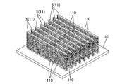
- the perspective view which shows the base part and the plate-shaped fin which also constitute a heat exchange structure.
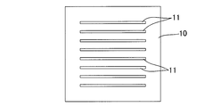
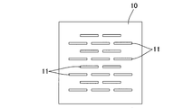
- an explanatory view of the base portion and the plate-shaped fins as viewed from the fin protruding side Similarly, an explanatory view showing a modified example of the arrangement form of the plate-shaped fins.
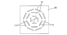
- FIGS. (A) and (B) are explanatory views showing still another modification of the arrangement form of the plate-shaped fins.
- explanatory view which shows the modification of the arrangement form of a base part and a plate-shaped fin.
- Explanatory drawing which shows the experimental apparatus. A graph showing the experimental results. A graph showing the experimental results as well. A photograph of the boiling aspect inside the container. Explanatory drawing which shows the relationship between a heating surface and a plate-shaped fin.
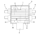
- FIG. 1 is a schematic view showing the overall configuration of the cooling device S including the heat exchange structure 1 according to the present invention.
- the cooling device S has a radiator 4 that accommodates the cooling liquid 3 that absorbs the heat of the object to be cooled 9 and dissipates the heat of the cooling liquid 3 in the container 2.
- the coolant 3 water and other liquids conventionally used as a coolant for the immersion type boiling cooling device can be widely adopted.
- various known radiators such as a water cooling system, an air cooling system, and a heat pipe heat transport system can be widely adopted according to the amount of heat radiated. As shown in FIG.
- a plate-shaped fin 11 may be projected to the outside of the base portion 10 which also serves as a container wall portion in a penetrating state, and the plate-shaped fin 11 protruding to the outside may be cooled by air cooling or the like as a radiator 4. .. In this case as well, various methods such as water cooling can be used in addition to air cooling.
- the upper portion 2a of the container 2 has a base portion 10 made of a good heat conductive material dissipated by the radiator 4 and the base portion 10.
- the bottom 2b of the container is provided with a holding hole 21 for holding the object 9 to be heated so as to penetrate inside, and the upper surface of the object 9 exposed to the coolant 3 serves as a heat generating surface 30 and functions as a bubble generating surface.
- heat may be transferred via another member (such as the bottom wall of the container).
- the temperature of the heating surface 30 rises, the difference between the temperature of the coolant 3 in the bottom region and the temperature of the coolant 3 in the other region that touches the temperature increases, and natural convection driven by buoyancy occurs.
- the temperature of the heat generating surface 30 becomes higher than the boiling point of the coolant 3
- boiling bubbles are generated from the heat generating surface in the coolant 3 in the bottom region, and strong convection driven by the bubbles is generated.
- the coolant that has generated convection in this way circulates between the plurality of plate-shaped fins 11, ..., And in the process, heat is efficiently taken out to the surface of the plate-shaped fins, and the heat is further transferred to the base portion 10.
- the radiator 4 efficiently dissipates heat.
- the heat exchange structure 1 of the present invention can positively utilize the convection phenomenon naturally occurring in the coolant in a high heat generation density environment as described above, and dramatically improves the heat exchange performance.
- the heat of the coolant can be efficiently taken out to the base portion 10 through the plate-shaped fins 11 and dissipated by the radiator 4 provided there without sending the coolant or its vapor to the external radiator. It is possible to eliminate a large-scale structure, reduce costs, and reduce the weight and size of the device.
- a metal material having good thermal conductivity such as aluminum, iron, and copper, which is conventionally used for heat sinks and the like, can be widely adopted. Both may be integrally formed (for example, aluminum die-cast molding or the like), or may be assembled by joining the separately formed ones by soldering or brazing.
- the plate-shaped fin 11 is formed with a plurality of through holes 110 that open on the plate surface. Even if it is a bottomed recess instead of the through hole 110, the heat transfer area of the plate surface when the convected coolant passes between the plate-shaped fins 11 is expanded, and the heat exchange efficiency is improved. In particular, in the case of the through hole 110, the coolant passes not only between the fins but also through the through hole 110, so that the heat of the coolant is taken out more efficiently through the plate-shaped fin 11. Become.
- Such a through hole 110 may be a through hole processed by a drill, a laser, or the like, but in this example, a lotus type porous metal molded body having a plurality of pores extending in one direction formed by a metal solidification method.
- the pores are made of a plate material (lotus fin 5) formed by cutting in a direction intersecting the extending direction of the pores, and the pores divided by the cutting are combined with the through hole 110 of the plate-shaped fin 11 (lotus fin 5).
- a lotus type porous metal molded body is molded by a known method such as a high pressure gas method (Pressurized Gas Method) (for example, a method disclosed in Japanese Patent No. 4235813) or a thermal decomposition method (Thermal Decomposition Method). can do.
- each plate-shaped fin 11 is rectangular, but the shape is not limited to this, and of course, a shape other than a rectangle such as a polygon or a semicircle can be used.
- the plate-shaped fins 11 of this example project from the lower surface of the base portion 10 in a direction perpendicular to (directly below), and are arranged in parallel with each other at a predetermined interval, but they do not have to be at right angles and have an angle. It may be in the direction of holding, or may be bent or curved (for example, wavy fins). This makes it possible to promote the flow through the fins. In addition, various arrangements are possible with respect to each other's arrangement relationship.
- a large number of relatively short plate-shaped fins 11 are arranged in a staggered pattern, or as shown in FIG. 6, arranged in multiple directions, as shown in FIG. 7 (a).
- a plurality of concentrically arranged plate-shaped fins that are bent into a circular shape (cylindrical shape), and plate-shaped fins 11 that are curved as shown in FIG. 7B are arranged intermittently with a gap along the circumferential direction. It is also preferable to provide a plurality of concentric circles.
- the plate-shaped fins 11 are provided with a plurality of through holes 110 as in this example, and the plate-shaped fins 11 curved as shown in FIGS. 7 (a) and 7 (b) are concentrically formed.
- the plate-shaped fins 11 curved as shown in FIGS. 7 (a) and 7 (b) are concentrically formed.
- Cooling liquid flows from the plate-shaped fins 11 forming a circle toward the plate-shaped fins 11 forming an outer circle through the through holes 110, and promotes the flow of the cooling liquid through the through holes 110 of each plate-shaped fin 11. It is preferable in that the heat exchange performance can be further improved.
- the base portion 10 also serves as the upper lid of the container 2, and the plate-shaped fins 11 are provided on the lower surface of the base portion 10, but the base portion constituting the side wall is provided on the upper portion of the side wall of the container.
- a plate-shaped fin may be provided on the inner surface side of the base portion toward the container central axis.
- the container A base portion 10 may be provided vertically on the side portion, and a plate-shaped fin 11 may be projected from the base portion 10 inward of the container.
- FIG. 9 a form in which the plate-shaped fins 11 extending from the left and right base portions 10 are connected, that is, a structure in which both ends of one plate-shaped fin 11 are supported by the left and right base portions 10 is also preferable. ..
- the base portion 10 is provided on the side portion of the container in this way, it can be configured to also serve as the side wall of the container 2.
- the heat exchange performance by the heat exchange structure 1 includes the arrangement form of the plate-shaped fins 11, the form of the through holes 110 of each plate-shaped fin 11 (porous structure), the water level of the coolant, the height of the immersion portion of each plate-shaped fin 11, and the like. It can be adjusted arbitrarily with. Although the embodiments of the present invention have been described above, the present invention is not limited to these examples, and it goes without saying that the present invention can be implemented in various forms without departing from the gist of the present invention.
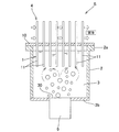
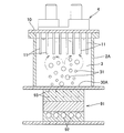
- the device used is composed of a heated copper block 91, a polycarbonate container 2A, a plate-shaped plate 11, a base portion 10, and a radiator 4.
- the upper end surface of the heated copper block 91 is a strip-shaped boiling heat transfer surface (10 mm ⁇ 80 mm), and the distilled water contained in the container is boiled.
- the generated vapor bubbles 31 rise and are condensed by the immersion fins (plate-shaped fins 11) projecting from the plate-shaped base portion 10.
- the radiator 4 provided on the upper part of the heat exchange plate (base portion 10) has a structure in which cooling water whose temperature is controlled by a chiller is circulated and cooled in a narrow flow path having a gap of 5 mm (set temperature is 60 degrees). ).
- the heating block 91 is thermally designed so that a heat transfer test can be performed up to a heat flux of 300 W / cm 2 . This is because the pool boiling limit heat flux of water calculated from Zuber's CHF correlation formula is about 110 W / cm 2 , so that a boiling heat transfer test close to CHF is surely carried out.
- Thermocouples 93 are loaded on the heated copper block 91 at positions 10 mm and 20 mm from the boiling heat transfer surface 30A at equal intervals of 5 rows in the lateral direction of the block, and the heat transfer surface temperature of 5 points is outside from these temperature data. It can be calculated by inserting it.
- the thermal conductivity ⁇ (W / m / K) of copper is obtained from the average temperature T a ⁇ (° C.) of the heat transfer surface at these five points by the following equation (1), and the average heat flux q (W) is obtained from the Fourier law (2). / Cm 2 ) is evaluated.
- the thermal resistance R SYS defined below is used to evaluate the heat transfer performance in this study.
- T in is the cooling water temperature at the inlet of the cooler
- T out is the cooling water temperature at the outlet of the cooler.
- R boil , R cond , and R cool are the thermal resistance of the boiling surface, the thermal resistance of the condensed portion, and the thermal resistance of the heat radiating portion, respectively.
- T l is the average temperature measured by two thermocouples installed in the glass container, and the saturation temperature is 100 ° C. in the high heat flux environment in the latter half of the experiment.
- T fin is the surface temperature of the heat exchange plate, and is measured by attaching an ultrafine thermocouple.
- the base portion 10 is a copper plate having a length x width of 140 x 140 mm and a thickness of 3 mm.
- the plate-shaped fins 11 are copper plate fins without holes / lotus copper (lotus type porous copper molded body) lotus fins, and a total of eight plates are soldered to the lower surface of the base portion 10 at intervals of 10 mm.
- the lotus copper used this time has an average pore diameter of 1.8 mm and a porosity of 39%.
- the base portion 10 and the lotus fin 11 were brought into contact with each other so that the lotus fin 11 was parallel to or perpendicular to the boiling heat transfer surface, and a heat transfer test was performed.
- Figure 12 (a), (b), the heat flux each case of 45W / cm 2, represents the thermal resistance of each part in the case of near CHF (110W / cm 2).
- Copper fin1 and Lotus fin1 show the case where the direction of the copper plate fin is perpendicular to the heat transfer surface, and Copper fin2 and Lotus fin2 show the case where the heat transfer surface is parallel to the lotus fin.
- the thermal resistance of the condensed part of the lotus fin is large, it can be seen that heat is not efficiently propagated from the coolant to the heat exchange plate. This is because the convection due to boiling is weak in the low heat flux, and the flow into the pores, which is expected to be utilized for lotus fins, is very weak, and as a result, the effective decrease in thermal conductivity of lotus fins becomes apparent. It is conceivable that.
- the effective thermal conductivity of the lotus fin made of lotus copper used this time in the vertical direction of the pores is about 84 W / m / K from the model formula, which is about 25% of that of the pure copper material.
- the ratio of each thermal resistance portion is 26 to 28% in the low heat flux region, whereas the copper fins are 26 to 28%. While lotus copper fins showed a high thermal resistance ratio of 47 to 50%, the ratio reversed near CHF, and while lotus copper fins showed a low thermal resistance ratio of 27 to 30%, copper fins 32 to 34%. It was. In particular, focusing only on the absolute value of the thermal resistance of the condensing part, although there is no significant difference between the two lotus fins, it is compared with the thermal resistance values of the copper plate fins (0.0176K / W and 0.0167K / W). It was confirmed that the thermal resistance was slightly reduced (0.0155 K / W / cm 2 and 0.0154 K / W).
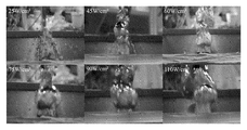
- FIG. 13 shows a change in the thermal resistance of the condensing part with respect to the heat flux
- FIG. 14 shows a photograph of the boiling aspect in the container at that time.
Landscapes
- Engineering & Computer Science (AREA)
- Life Sciences & Earth Sciences (AREA)
- Sustainable Development (AREA)
- Physics & Mathematics (AREA)
- Thermal Sciences (AREA)
- Mechanical Engineering (AREA)
- General Engineering & Computer Science (AREA)
- Cooling Or The Like Of Semiconductors Or Solid State Devices (AREA)
- Cooling Or The Like Of Electrical Apparatus (AREA)
Applications Claiming Priority (2)
| Application Number | Priority Date | Filing Date | Title |
|---|---|---|---|
| JP2019-095519 | 2019-05-21 | ||
| JP2019095519A JP7352848B2 (ja) | 2019-05-21 | 2019-05-21 | 冷却装置における冷却液の熱を取り出す熱交換構造、及び該熱交換構造を備える冷却装置 |
Publications (1)
| Publication Number | Publication Date |
|---|---|
| WO2020235217A1 true WO2020235217A1 (ja) | 2020-11-26 |
Family
ID=73458576
Family Applications (1)
| Application Number | Title | Priority Date | Filing Date |
|---|---|---|---|
| PCT/JP2020/013813 Ceased WO2020235217A1 (ja) | 2019-05-21 | 2020-03-26 | 冷却装置における冷却液の熱を取り出す熱交換構造、及び該熱交換構造を備える冷却装置 |
Country Status (2)
| Country | Link |
|---|---|
| JP (1) | JP7352848B2 (https=) |
| WO (1) | WO2020235217A1 (https=) |
Cited By (2)
| Publication number | Priority date | Publication date | Assignee | Title |
|---|---|---|---|---|
| CN113163678A (zh) * | 2021-03-26 | 2021-07-23 | 中国石油大学(华东) | 一种基于离子风的新型耦合冷却装置、冷却方法及其应用 |
| WO2022244628A1 (ja) * | 2021-05-20 | 2022-11-24 | 株式会社ロータス・サーマル・ソリューション | ヒートシンク構造 |
Families Citing this family (2)
| Publication number | Priority date | Publication date | Assignee | Title |
|---|---|---|---|---|
| KR102855737B1 (ko) * | 2024-03-20 | 2025-09-05 | 인하대학교 산학협력단 | 유동 가이드와 비등 냉각 기법을 적용한 액침 냉각 장치 및 그 방법 |
| JP2026057221A (ja) * | 2024-09-20 | 2026-04-02 | 古河電気工業株式会社 | 沸騰促進部およびベーパチャンバ |
Citations (4)
| Publication number | Priority date | Publication date | Assignee | Title |
|---|---|---|---|---|
| JPS4921148U (https=) * | 1972-05-27 | 1974-02-22 | ||
| JPH0157503B2 (https=) * | 1980-10-14 | 1989-12-06 | Fujitsu Ltd | |
| JP2005228948A (ja) * | 2004-02-13 | 2005-08-25 | Mitsubishi Electric Corp | ヒートシンク |
| JP2015025750A (ja) * | 2013-07-26 | 2015-02-05 | アンリツ産機システム株式会社 | X線発生装置及びx線検査装置 |
Family Cites Families (1)
| Publication number | Priority date | Publication date | Assignee | Title |
|---|---|---|---|---|
| JP5678662B2 (ja) | 2008-11-18 | 2015-03-04 | 日本電気株式会社 | 沸騰冷却装置 |
-
2019
- 2019-05-21 JP JP2019095519A patent/JP7352848B2/ja active Active
-
2020
- 2020-03-26 WO PCT/JP2020/013813 patent/WO2020235217A1/ja not_active Ceased
Patent Citations (4)
| Publication number | Priority date | Publication date | Assignee | Title |
|---|---|---|---|---|
| JPS4921148U (https=) * | 1972-05-27 | 1974-02-22 | ||
| JPH0157503B2 (https=) * | 1980-10-14 | 1989-12-06 | Fujitsu Ltd | |
| JP2005228948A (ja) * | 2004-02-13 | 2005-08-25 | Mitsubishi Electric Corp | ヒートシンク |
| JP2015025750A (ja) * | 2013-07-26 | 2015-02-05 | アンリツ産機システム株式会社 | X線発生装置及びx線検査装置 |
Cited By (3)
| Publication number | Priority date | Publication date | Assignee | Title |
|---|---|---|---|---|
| CN113163678A (zh) * | 2021-03-26 | 2021-07-23 | 中国石油大学(华东) | 一种基于离子风的新型耦合冷却装置、冷却方法及其应用 |
| WO2022244628A1 (ja) * | 2021-05-20 | 2022-11-24 | 株式会社ロータス・サーマル・ソリューション | ヒートシンク構造 |
| JP7637880B2 (ja) | 2021-05-20 | 2025-03-03 | 株式会社ロータス・サーマル・ソリューション | ヒートシンク構造 |
Also Published As
| Publication number | Publication date |
|---|---|
| JP2022107071A (ja) | 2022-07-21 |
| JP7352848B2 (ja) | 2023-09-29 |
Similar Documents
| Publication | Publication Date | Title |
|---|---|---|
| WO2020235217A1 (ja) | 冷却装置における冷却液の熱を取り出す熱交換構造、及び該熱交換構造を備える冷却装置 | |
| CN214582684U (zh) | 冷却装置及使用冷却装置的冷却系统 | |
| US12050061B2 (en) | Shrouded powder patch | |
| JP6015675B2 (ja) | 冷却装置及びそれを用いた電子機器 | |
| TWI768320B (zh) | 冷卻裝置 | |
| CN212673920U (zh) | 散热器 | |
| US20120211204A1 (en) | Multidimensional heat transfer system for cooling electronic components | |
| KR20180061271A (ko) | 전자 회로 카드 모듈에서의 멀티 레벨 오실레이팅 히트 파이프 구현 | |
| US20210125898A1 (en) | Vapor chamber | |
| JP7220434B2 (ja) | 沸騰冷却構造 | |
| KR102037682B1 (ko) | 냉각장치 및 수처리 기기의 냉수 저장 장치 | |
| JP2016009828A (ja) | 発熱素子用沸騰冷却器 | |
| CN108029221B (zh) | 冷却器、电力转换装置及冷却系统 | |
| TWI300468B (en) | Systems for improved passive liquid cooling | |
| JP6376967B2 (ja) | 沸騰伝熱部材およびこれを用いた沸騰冷却装置 | |
| WO2015104842A1 (ja) | 冷却装置 | |
| JP5860728B2 (ja) | 電子機器の冷却システム | |
| JP5827559B2 (ja) | 冷却器 | |
| JP2021188886A (ja) | 伝熱部材および伝熱部材を有する冷却デバイス | |
| JP2016133230A (ja) | 放熱装置 | |
| KR20070107214A (ko) | 컴퓨터 냉각 구조 | |
| JP2007080989A (ja) | ヒートシンク | |
| JP2010022711A (ja) | 放熱用水枕 | |
| CN222071155U (zh) | 一种用于高功率密度处理器的冷却装置 | |
| JP7399742B2 (ja) | 冷却装置 |
Legal Events
| Date | Code | Title | Description |
|---|---|---|---|
| 121 | Ep: the epo has been informed by wipo that ep was designated in this application |
Ref document number: 20809036 Country of ref document: EP Kind code of ref document: A1 |
|
| NENP | Non-entry into the national phase |
Ref country code: DE |
|
| 122 | Ep: pct application non-entry in european phase |
Ref document number: 20809036 Country of ref document: EP Kind code of ref document: A1 |
|
| NENP | Non-entry into the national phase |
Ref country code: JP |