WO2020230619A1 - 車両制御システム - Google Patents
車両制御システム Download PDFInfo
- Publication number
- WO2020230619A1 WO2020230619A1 PCT/JP2020/018068 JP2020018068W WO2020230619A1 WO 2020230619 A1 WO2020230619 A1 WO 2020230619A1 JP 2020018068 W JP2020018068 W JP 2020018068W WO 2020230619 A1 WO2020230619 A1 WO 2020230619A1
- Authority
- WO
- WIPO (PCT)
- Prior art keywords
- information
- sensor
- detection information
- grouping
- arithmetic unit
- Prior art date
- Legal status (The legal status is an assumption and is not a legal conclusion. Google has not performed a legal analysis and makes no representation as to the accuracy of the status listed.)
- Ceased
Links
Images



Classifications
-
- G—PHYSICS
- G06—COMPUTING OR CALCULATING; COUNTING
- G06V—IMAGE OR VIDEO RECOGNITION OR UNDERSTANDING
- G06V20/00—Scenes; Scene-specific elements
- G06V20/50—Context or environment of the image
- G06V20/56—Context or environment of the image exterior to a vehicle by using sensors mounted on the vehicle
- G06V20/58—Recognition of moving objects or obstacles, e.g. vehicles or pedestrians; Recognition of traffic objects, e.g. traffic signs, traffic lights or roads
-
- B—PERFORMING OPERATIONS; TRANSPORTING
- B60—VEHICLES IN GENERAL
- B60W—CONJOINT CONTROL OF VEHICLE SUB-UNITS OF DIFFERENT TYPE OR DIFFERENT FUNCTION; CONTROL SYSTEMS SPECIALLY ADAPTED FOR HYBRID VEHICLES; ROAD VEHICLE DRIVE CONTROL SYSTEMS FOR PURPOSES NOT RELATED TO THE CONTROL OF A PARTICULAR SUB-UNIT
- B60W60/00—Drive control systems specially adapted for autonomous road vehicles
- B60W60/001—Planning or execution of driving tasks
-
- B—PERFORMING OPERATIONS; TRANSPORTING
- B60—VEHICLES IN GENERAL
- B60W—CONJOINT CONTROL OF VEHICLE SUB-UNITS OF DIFFERENT TYPE OR DIFFERENT FUNCTION; CONTROL SYSTEMS SPECIALLY ADAPTED FOR HYBRID VEHICLES; ROAD VEHICLE DRIVE CONTROL SYSTEMS FOR PURPOSES NOT RELATED TO THE CONTROL OF A PARTICULAR SUB-UNIT
- B60W40/00—Estimation or calculation of non-directly measurable driving parameters for road vehicle drive control systems not related to the control of a particular sub unit, e.g. by using mathematical models
- B60W40/02—Estimation or calculation of non-directly measurable driving parameters for road vehicle drive control systems not related to the control of a particular sub unit, e.g. by using mathematical models related to ambient conditions
- B60W40/04—Traffic conditions
-
- B—PERFORMING OPERATIONS; TRANSPORTING
- B60—VEHICLES IN GENERAL
- B60W—CONJOINT CONTROL OF VEHICLE SUB-UNITS OF DIFFERENT TYPE OR DIFFERENT FUNCTION; CONTROL SYSTEMS SPECIALLY ADAPTED FOR HYBRID VEHICLES; ROAD VEHICLE DRIVE CONTROL SYSTEMS FOR PURPOSES NOT RELATED TO THE CONTROL OF A PARTICULAR SUB-UNIT
- B60W50/00—Details of control systems for road vehicle drive control not related to the control of a particular sub-unit, e.g. process diagnostic or vehicle driver interfaces
- B60W50/02—Ensuring safety in case of control system failures, e.g. by diagnosing, circumventing or fixing failures
- B60W50/023—Avoiding failures by using redundant parts
-
- G—PHYSICS
- G01—MEASURING; TESTING
- G01S—RADIO DIRECTION-FINDING; RADIO NAVIGATION; DETERMINING DISTANCE OR VELOCITY BY USE OF RADIO WAVES; LOCATING OR PRESENCE-DETECTING BY USE OF THE REFLECTION OR RERADIATION OF RADIO WAVES; ANALOGOUS ARRANGEMENTS USING OTHER WAVES
- G01S13/00—Systems using the reflection or reradiation of radio waves, e.g. radar systems; Analogous systems using reflection or reradiation of waves whose nature or wavelength is irrelevant or unspecified
- G01S13/86—Combinations of radar systems with non-radar systems, e.g. sonar, direction finder
- G01S13/867—Combination of radar systems with cameras
-
- G—PHYSICS
- G01—MEASURING; TESTING
- G01S—RADIO DIRECTION-FINDING; RADIO NAVIGATION; DETERMINING DISTANCE OR VELOCITY BY USE OF RADIO WAVES; LOCATING OR PRESENCE-DETECTING BY USE OF THE REFLECTION OR RERADIATION OF RADIO WAVES; ANALOGOUS ARRANGEMENTS USING OTHER WAVES
- G01S13/00—Systems using the reflection or reradiation of radio waves, e.g. radar systems; Analogous systems using reflection or reradiation of waves whose nature or wavelength is irrelevant or unspecified
- G01S13/88—Radar or analogous systems specially adapted for specific applications
- G01S13/93—Radar or analogous systems specially adapted for specific applications for anti-collision purposes
- G01S13/931—Radar or analogous systems specially adapted for specific applications for anti-collision purposes of land vehicles
-
- G—PHYSICS
- G01—MEASURING; TESTING
- G01S—RADIO DIRECTION-FINDING; RADIO NAVIGATION; DETERMINING DISTANCE OR VELOCITY BY USE OF RADIO WAVES; LOCATING OR PRESENCE-DETECTING BY USE OF THE REFLECTION OR RERADIATION OF RADIO WAVES; ANALOGOUS ARRANGEMENTS USING OTHER WAVES
- G01S7/00—Details of systems according to groups G01S13/00, G01S15/00, G01S17/00
- G01S7/02—Details of systems according to groups G01S13/00, G01S15/00, G01S17/00 of systems according to group G01S13/00
- G01S7/40—Means for monitoring or calibrating
-
- G—PHYSICS
- G06—COMPUTING OR CALCULATING; COUNTING
- G06V—IMAGE OR VIDEO RECOGNITION OR UNDERSTANDING
- G06V10/00—Arrangements for image or video recognition or understanding
- G06V10/40—Extraction of image or video features
- G06V10/62—Extraction of image or video features relating to a temporal dimension, e.g. time-based feature extraction; Pattern tracking
-
- G—PHYSICS
- G06—COMPUTING OR CALCULATING; COUNTING
- G06V—IMAGE OR VIDEO RECOGNITION OR UNDERSTANDING
- G06V10/00—Arrangements for image or video recognition or understanding
- G06V10/70—Arrangements for image or video recognition or understanding using pattern recognition or machine learning
- G06V10/77—Processing image or video features in feature spaces; using data integration or data reduction, e.g. principal component analysis [PCA] or independent component analysis [ICA] or self-organising maps [SOM]; Blind source separation
- G06V10/80—Fusion, i.e. combining data from various sources at the sensor level, preprocessing level, feature extraction level or classification level
- G06V10/809—Fusion, i.e. combining data from various sources at the sensor level, preprocessing level, feature extraction level or classification level of classification results, e.g. where the classifiers operate on the same input data
- G06V10/811—Fusion, i.e. combining data from various sources at the sensor level, preprocessing level, feature extraction level or classification level of classification results, e.g. where the classifiers operate on the same input data the classifiers operating on different input data, e.g. multi-modal recognition
-
- B—PERFORMING OPERATIONS; TRANSPORTING
- B60—VEHICLES IN GENERAL
- B60W—CONJOINT CONTROL OF VEHICLE SUB-UNITS OF DIFFERENT TYPE OR DIFFERENT FUNCTION; CONTROL SYSTEMS SPECIALLY ADAPTED FOR HYBRID VEHICLES; ROAD VEHICLE DRIVE CONTROL SYSTEMS FOR PURPOSES NOT RELATED TO THE CONTROL OF A PARTICULAR SUB-UNIT
- B60W2420/00—Indexing codes relating to the type of sensors based on the principle of their operation
- B60W2420/40—Photo, light or radio wave sensitive means, e.g. infrared sensors
- B60W2420/403—Image sensing, e.g. optical camera
-
- B—PERFORMING OPERATIONS; TRANSPORTING
- B60—VEHICLES IN GENERAL
- B60W—CONJOINT CONTROL OF VEHICLE SUB-UNITS OF DIFFERENT TYPE OR DIFFERENT FUNCTION; CONTROL SYSTEMS SPECIALLY ADAPTED FOR HYBRID VEHICLES; ROAD VEHICLE DRIVE CONTROL SYSTEMS FOR PURPOSES NOT RELATED TO THE CONTROL OF A PARTICULAR SUB-UNIT
- B60W2420/00—Indexing codes relating to the type of sensors based on the principle of their operation
- B60W2420/40—Photo, light or radio wave sensitive means, e.g. infrared sensors
- B60W2420/408—Radar; Laser, e.g. lidar
-
- B—PERFORMING OPERATIONS; TRANSPORTING
- B60—VEHICLES IN GENERAL
- B60W—CONJOINT CONTROL OF VEHICLE SUB-UNITS OF DIFFERENT TYPE OR DIFFERENT FUNCTION; CONTROL SYSTEMS SPECIALLY ADAPTED FOR HYBRID VEHICLES; ROAD VEHICLE DRIVE CONTROL SYSTEMS FOR PURPOSES NOT RELATED TO THE CONTROL OF A PARTICULAR SUB-UNIT
- B60W2554/00—Input parameters relating to objects
- B60W2554/40—Dynamic objects, e.g. animals, windblown objects
- B60W2554/404—Characteristics
- B60W2554/4041—Position
-
- B—PERFORMING OPERATIONS; TRANSPORTING
- B60—VEHICLES IN GENERAL
- B60W—CONJOINT CONTROL OF VEHICLE SUB-UNITS OF DIFFERENT TYPE OR DIFFERENT FUNCTION; CONTROL SYSTEMS SPECIALLY ADAPTED FOR HYBRID VEHICLES; ROAD VEHICLE DRIVE CONTROL SYSTEMS FOR PURPOSES NOT RELATED TO THE CONTROL OF A PARTICULAR SUB-UNIT
- B60W2556/00—Input parameters relating to data
- B60W2556/20—Data confidence level
-
- B—PERFORMING OPERATIONS; TRANSPORTING
- B60—VEHICLES IN GENERAL
- B60W—CONJOINT CONTROL OF VEHICLE SUB-UNITS OF DIFFERENT TYPE OR DIFFERENT FUNCTION; CONTROL SYSTEMS SPECIALLY ADAPTED FOR HYBRID VEHICLES; ROAD VEHICLE DRIVE CONTROL SYSTEMS FOR PURPOSES NOT RELATED TO THE CONTROL OF A PARTICULAR SUB-UNIT
- B60W2556/00—Input parameters relating to data
- B60W2556/25—Data precision
-
- B—PERFORMING OPERATIONS; TRANSPORTING
- B60—VEHICLES IN GENERAL
- B60W—CONJOINT CONTROL OF VEHICLE SUB-UNITS OF DIFFERENT TYPE OR DIFFERENT FUNCTION; CONTROL SYSTEMS SPECIALLY ADAPTED FOR HYBRID VEHICLES; ROAD VEHICLE DRIVE CONTROL SYSTEMS FOR PURPOSES NOT RELATED TO THE CONTROL OF A PARTICULAR SUB-UNIT
- B60W2556/00—Input parameters relating to data
- B60W2556/30—Data update rate
-
- B—PERFORMING OPERATIONS; TRANSPORTING
- B60—VEHICLES IN GENERAL
- B60W—CONJOINT CONTROL OF VEHICLE SUB-UNITS OF DIFFERENT TYPE OR DIFFERENT FUNCTION; CONTROL SYSTEMS SPECIALLY ADAPTED FOR HYBRID VEHICLES; ROAD VEHICLE DRIVE CONTROL SYSTEMS FOR PURPOSES NOT RELATED TO THE CONTROL OF A PARTICULAR SUB-UNIT
- B60W2556/00—Input parameters relating to data
- B60W2556/35—Data fusion
Definitions
- This disclosure relates to a vehicle control system.
- Patent Document 1 discloses a calibration device having the following configuration.
- the calibration device is "Is the obstacle suitable for detecting the displacement between the first measuring device 11 and the second measuring device 12 based on the geometric shape measured by the first measuring device 11?"
- the misalignment determination permission unit 114 for determining whether or not the position is not present, the position detected by the first measuring device 11 for the obstacle determined by the misalignment determination permission unit 114 to be an obstacle suitable for detecting the misalignment, and
- An inter-sensor calibration unit 117 for detecting the amount of misalignment between the first measuring device 11 and the second measuring device 12 based on the position detected by the second measuring device 12 with respect to the obstacle is provided. ” , See summary section).
- the behavior recognition device 30 of Patent Document 2 is a set (Xp, Yp) of "a person p, the sensor data Xp detected by the first sensor 10 and the sensor data Yp detected by the second sensor 20".
- a storage unit 32 that stores training data
- an estimation unit 332 that calculates an estimated value Ye (Xp') of sensor data Yp'for arbitrary sensor data Xp'based on the training data, and an estimated value Ye (Xp').
- the similarity Cij with the collected sensor data Yj is calculated, and based on the calculated temporal transition of the similarity Cij, the matching score Pij indicating the high possibility that the person i and the person j are the same person is calculated.
- the sensor data collation unit 333 is provided, and the person determination unit 334 that determines whether or not the person i and the person j are the same person based on the value of the collation score Pij. ”(See the same document and summary column). ..
- the conventional obstacle detection device described in Patent Document 1 has an obstacle position detected by the first measuring device and an obstacle detected by the second measuring device at each time of t, t + 1, t + 2, ..., T + n. When the positions overlap, it is determined that the two obstacles are the same obstacle (see the same document, paragraph 0034, etc.).
- the instantaneous value grouping that determines whether or not the obstacles detected by a plurality of measuring devices are the same at each time may include an error in the determination result. , High-precision grouping is difficult.
- the present disclosure provides a vehicle control system capable of grouping a plurality of detection results of the same object detected by a plurality of sensors with high accuracy and in a short time.
- One aspect of the present disclosure is the first sensor and the second sensor that detect an object around the vehicle, and the first detection information and the first detection information that are the detection results of the first sensor and the second sensor that detect the same object.
- a vehicle control system including an information integration device that groups detection information and outputs integrated detection information, and a vehicle control device that controls a vehicle based on the integrated detection information.
- the device includes a calculation device and a storage device, and the calculation device includes a first time-series information which is time-series information of the first detection information and a second time-series information which is time-series information of the second detection information.
- the correction parameter is calculated, the correction information obtained by correcting the first detection information using the correction parameter is calculated, and the integrated detection information is output by instantaneous value grouping using the correction information and the second detection information. It is a vehicle control system characterized by this.
- a vehicle control system capable of grouping a plurality of detection results of the same object detected by a plurality of sensors with high accuracy and in a short time.
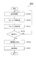
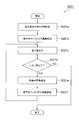
- FIG. 5 is a flow chart showing processing of an information integration device constituting the vehicle control system of FIG. 1.
- FIG. 2 is a flow chart of detection information integration included in the processing of the information integration device shown in FIG.
- the correction flow diagram included in the detection information integration shown in FIG. The flow chart of the correction parameter calculation included in the detection information integration shown in FIG.
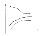
- the graph which shows an example of the time series information of the outside world sensor of the vehicle control system of FIG.
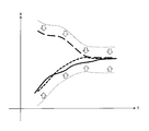
- the graph which shows the grouping result of the conventional obstacle detection device.
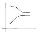
- the graph which shows the grouping result of the information integration apparatus of the vehicle control system of FIG. The flow chart of the calibration judgment by the vehicle control system which concerns on Embodiment 2 of this disclosure.
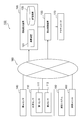
- FIG. 1 is a block diagram showing a configuration example of the vehicle control system 100 of the present embodiment.
- the vehicle control system 100 is mounted on a vehicle such as an automobile, and constitutes an advanced driver assistance system (ADAS) or an automatic driving (AD) system for the vehicle.
- the vehicle control system 100 includes, for example, an external sensor 110, an information integration device 120, and a vehicle control device 130. Further, the vehicle control system 100 may include, for example, a vehicle sensor 140, a positioning system 150, a map unit 160, and an actuator 170.
- ADAS advanced driver assistance system
- AD automatic driving
- the outside world sensor 110 is a sensor for detecting an object around the vehicle on which the vehicle control system 100 is mounted.
- the external sensor 110 detects, for example, the relative position, relative speed, shape and type of an object around the vehicle on which the vehicle control system 100 is mounted.
- Objects around a vehicle include, for example, other vehicles, pedestrians, roads, sidewalks, road markings such as white lines, signs, traffic lights, curbs, guardrails, structures and other obstacles.
- the external sensor 110 includes, for example, two sensors, a first sensor 111 and a second sensor 112.
- the first sensor 111 and the second sensor 112 are, for example, different types of sensors having different object detection principles. Further, the external sensor 110 may include three or more different types of sensors, or may include a plurality of sensors of the same type.
- the external sensor 110 is connected to the information integration device 120 and the vehicle control device 130 via a communication network 180 such as CAN (Controller Area Network), Ethernet (registered trademark), and wireless communication so as to enable data communication.
- CAN Controller Area Network
- Ethernet registered trademark
- Examples of the plurality of sensors included in the external world sensor 110 include a millimeter-wave radar device, an imaging device including a monocular camera and a stereo camera, an ultrasonic sonar, and a laser radar device.
- the first sensor 111 is, for example, a sensor that detects the three-dimensional shape of an object around the vehicle and the distance to the object.
- the first sensor 111 is, for example, an imaging device.
- the second sensor 112 is, for example, a sensor that measures the distance to an object around the vehicle.
- the second sensor 112 is, for example, a distance measuring device such as a millimeter wave radar device or a laser radar device.
- the information integration device 120 groups the detection results of some sensors that have detected the same object among the plurality of sensors included in the external world sensor 110, and outputs integrated detection information in which these detection results are integrated. .. More specifically, the information integration device 120 is integrated by grouping, for example, the first detection information and the second detection information, which are the detection results of the first sensor 111 and the second sensor 112 that have detected the same object. Output integrated detection information.
- the information integration device 120 is connected to the vehicle sensor 140, the outside world sensor 110, the positioning system 150, the map unit 160, and the vehicle control device 130 via a communication network 180 so as to be capable of data communication.
- the information integration device 120 includes, for example, an arithmetic unit 121 and a storage device 122.
- the arithmetic unit 121 is, for example, one or more central processing units (CPUs).
- the storage device 122 includes, for example, one or more main storage devices and auxiliary storage devices.
- the storage device 122 can be configured by, for example, a hard disk or a memory.
- the information integration device 120 includes, for example, a terminal unit for inputting / outputting signals and an input device for inputting set values and the like.
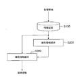
- FIG. 2 is a flow chart showing an example of processing of the information integration device 120.
- the arithmetic unit 121 of the information integration device 120 acquires various information via the communication network 180 in the information storage S100 and stores it in the storage device 122.
- the storage device 122 stores various information such as behavior information and position information of the vehicle on which the vehicle control system 100 is mounted, detection information of objects around the vehicle, road information, and map information. To.
- the arithmetic unit 121 outputs integrated detection information that integrates a plurality of detection information of the same object among the detection information of the plurality of sensors of the external world sensor 110 stored in the storage device 122.
- the plurality of detection information to be integrated includes, for example, first detection information and second detection information which are the detection results of the object by the first sensor 111 and the second sensor 112.
- the arithmetic unit 121 integrates the above-mentioned integrated detection information with various information acquired from the storage device 122, for example, vehicle behavior information and position information, and road information and map information around the vehicle. And output the environment information.
- the output environmental information is input to the vehicle control device 130 shown in FIG.
- the vehicle control device 130 controls the vehicle based on the integrated detection information output from the information integration device 120. More specifically, the vehicle control device 130 controls the vehicle based on the environment information around the vehicle in which the integrated detection information of the object and various other information are integrated.
- the vehicle control device 130 is connected to, for example, a vehicle sensor 140, an outside world sensor 110, a positioning system 150, a map unit 160, an information integration device 120, and an actuator 170 so as to be capable of data communication.
- the vehicle control device 130 determines, for example, the travel path and speed of the vehicle equipped with the vehicle control system 100 based on the outputs from the vehicle sensor 140, the outside world sensor 110, the positioning system 150, the map unit 160, and the information integration device 120. Generate a driving plan including acceleration and so on.
- the vehicle control device 130 realizes ADAS and AD by controlling the actuator 170 based on the generated travel plan.
- the vehicle sensor 140 is a sensor that measures the speed, acceleration, steering angle, yaw rate, etc. of a vehicle equipped with the vehicle control system 100.
- the vehicle sensor 140 includes, for example, a gyro sensor, a wheel speed sensor, a steering angle sensor, an acceleration sensor, a brake sensor, an accelerator sensor, a speed change sensor, and the like.
- the vehicle sensor 140 is connected to the information integration device 120 and the vehicle control device 130 so as to be capable of data communication via, for example, the communication network 180.
- the positioning system 150 measures the position of the vehicle on which the vehicle control system 100 is mounted.
- a satellite positioning system such as GNSS (Global Navigation Satellite System) or GPS (Global Positioning System) can be used.
- the positioning system 150 is connected to the information integration device 120, the vehicle control device 130, and the map unit 160 via a communication network 180, for example, so that data communication is possible.
- the map unit 160 is composed of, for example, an arithmetic unit and a storage device, acquires the position of the vehicle on which the vehicle control system 100 is mounted from the positioning system 150, selects and outputs map information around the vehicle.
- the map unit 160 is connected to the information integration device 120, the vehicle control device 130, and the positioning system 150 via a communication network 180, for example, so that data communication is possible.
- the actuator 170 for example, runs a vehicle equipped with the vehicle control system 100 according to command information from the vehicle control device 130. Specifically, the actuator 170 realizes ADAS or AD of the vehicle by operating the accelerator, brake, transmission, steering, direction indicator, etc. of the vehicle according to the instruction information from the vehicle control device 130, for example. ..
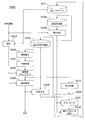
- FIG. 3 is a flow chart showing details of the detection information integration S200 included in the processing of the information integration device 120 shown in FIG.
- the detection information integrated S200 is, for example, a correction S201, an instantaneous value grouping S202, an integrated update S203, an integrated detection information time series S204, an integrated time series information storage S205, and an integrated time series information instantaneous value conversion. Includes S206 and predictive update S207 of integrated detection information. Further, the detection information integration S200 includes, for example, a time-series detection information S208, a time-series information storage S209, a calibration determination S210, a calibration S220, and a correction parameter storage S211.
- the arithmetic unit 121 of the information integration device 120 has the detection information of a specific sensor among the plurality of detection information which is the detection result of the object by the plurality of sensors of the external world sensor 110 stored in the storage device 122.
- the arithmetic unit 121 is the first of the first sensor 111 among a plurality of detection information including, for example, the first detection information of the first sensor 111 and the second detection information of the second sensor 112. Correct the detection information.
- the first sensor 111 is an image pickup device such as a stereo camera, and the first detection information is the position and speed of the object detected by the image pickup device.
- the second sensor 112 is, for example, a millimeter-wave radar device, and the second detection information is the position and speed of an object detected by the millimeter-wave radar device.
- FIG. 4 is a flow chart of the correction S201 included in the detection information integration S200 of FIG.
- the correction S201 includes, for example, a detection information selection S201a, a sensor observation amount calculation S201b, a sensor observation amount correction S201c, a correction information calculation S201d, and an end determination S201e.
- the arithmetic unit 121 selects the detection information of one of the plurality of sensors of the external world sensor 110 in the detection information selection S201a. More specifically, the arithmetic unit 121 selects, for example, the first detection information of the first sensor 111 in the detection information selection S201a. Next, the arithmetic unit 121 calculates the observation amount of the selected sensor from the detection information of the selected sensor in the sensor observation amount calculation S201b. Next, the arithmetic unit 121 corrects the observation amount of the sensor by using the correction parameter acquired from the storage device 122 in the sensor observation amount correction S201c. Next, in the correction information calculation S201d, the arithmetic unit 121 calculates the correction information, which is the corrected detection information, by using the observed amount of the sensor after the correction.
- the arithmetic unit 121 determines the pixel position, which is the sensor observation amount, from, for example, the position and speed of the object which is the first detection information of the first sensor 111 which is the image sensor. calculate.
- the sensor observation amount correction S201c the arithmetic unit 121 corrects the pixel position, which is the observation amount of the first sensor 111, which is an image sensor, by using, for example, the correction parameter acquired from the storage device 122.
- the correction information calculation S201d the arithmetic unit 121 calculates, for example, the position and speed of the object based on the corrected pixel position as the correction information.
- the observed amount of the second sensor 112, which is a millimeter-wave radar device is, for example, the distance and angle from the second sensor 112 to the object.
- the arithmetic unit 121 determines in the end determination S201e whether or not the calculation of the correction information of all the sensors for which the correction information is to be calculated is completed. When the arithmetic unit 121 determines that the calculation of the correction information has not been completed (NO) for all the sensors for which the correction information is calculated, the calculation device 121 returns to the detection information selection S201a. The arithmetic unit 121 terminates the correction S201 when it determines that the calculation of the correction information is completed (YES) for all the sensors for which the correction information is calculated.
- the storage device 122 stores the correction parameters used in the correction S201 at the time of product shipment of a plurality of sensors including the first sensor 111 constituting the external world sensor 110.
- the correction parameter stored in the storage device 122 is updated, for example, in the correction parameter storage S211 described later.
- the arithmetic unit 121 After the completion of the correction S201 shown in FIGS. 3 and 4, the arithmetic unit 121 performs the following processing in the instantaneous value grouping S202.
- the arithmetic unit 121 used the correction information calculated for the sensor targeted by the correction S201 and the detection information from the sensor not covered by the correction S201 among the plurality of sensors constituting the external world sensor 110. Perform instantaneous value grouping.
- the arithmetic unit 121 outputs integrated detection information of the same object detected by a plurality of sensors constituting the external world sensor 110.
- the arithmetic unit 121 corrects the first detection information of the first sensor 111, which is an image pickup device, and the correction information, for example, of the second sensor 112, which is a millimeter wave radar device.
- Instantaneous value grouping is performed using the second detection information.
- the instantaneous value grouping uses a method different from the time series information of the detection information and the correction information of the sensor, that is, the time series grouping based on the time transition of the detection information and the correction information.
- the detection information and the correction information of a plurality of sensors are grouped by using the instantaneous value of the detection information of the sensors, that is, the detection information acquired by one sampling and the correction information thereof.
- the arithmetic unit 121 uses, for example, the following equation (1) stored in the storage device 122 to perform instantaneous value grouping of detection information and correction information of a plurality of sensors constituting the external world sensor 110. Equation (1) represents the Mahalanobis distance.
- the arithmetic unit 121 uses, for example, prediction information of detection information and correction information of a plurality of sensors constituting the external world sensor 110. This prediction information is calculated in the prediction update S207 of the integrated detection information described later.
- xs, j, t are, for example, detection information or correction information
- xp, i, t are prediction information of these detection information and correction information.
- the detection information or the correction information follows a normal distribution with the predicted values averaged, and the information that the covariance is Pp, i, t, s, j, t is obtained.
- the subscript p represents a prediction
- s represents a sensor
- i represents an identification number of a predicted value
- j represents an identification number of detection information or correction information
- t represents a time point.
- the Mahalanobis distance between the detection information and the correction information and their predicted values is expressed by the above equation (1).
- the arithmetic unit 121 targets detection information or correction information of a plurality of sensors for grouping, for example, when the Mahalanobis distance is equal to or less than a threshold value. Then, the arithmetic unit 121 stores the predicted values of the detection information and the correction information, and the detection information or the identification number of the correction information of the plurality of sensors targeted for grouping in the storage device 122.
- the arithmetic unit 121 sets the detection information and the correction information of the plurality of sensors constituting the external world sensor 110 and the identification number of the grouping target detection information or the correction information in the integrated update S203. Based on this, the integrated detection information is output.
- This integrated detection information is, for example, information that estimates the state of an object detected by a plurality of sensors constituting the external world sensor 110.
- the arithmetic unit 121 uses the integrated detection information output in the integrated update S203, and outputs the environmental information in the environmental information integrated S300 shown in FIG. 2 as described above.
- the arithmetic unit 121 outputs the integrated time series information which is the time series of the past integrated detection information stored in the storage device 122 by the integrated update S203. Add the latest integrated detection information. Then, the arithmetic unit 121 outputs the latest integrated time series information to which the latest integrated detection information is added. Further, the arithmetic unit 121 stores the latest integrated time series information in the storage device 122 in the integrated time series information storage S205.
- the arithmetic unit 121 instantaneously digitizes the integrated time series information stored in the storage device 122 in the integrated time series information instantiation S206, and instantly digitizes the integrated detection information in the prediction update S207.
- Prediction information is output using the integrated detection information.
- This prediction information is, for example, the result of predicting the state of an object detected by a plurality of sensors constituting the external world sensor 110 after the time interval for performing sensor fusion has elapsed. is there.
- This prediction information is used, for example, in the instantaneous value grouping S202 as described above.
- the storage device 122 stores, for example, time-series information which is a time-series of past detection information of a plurality of sensors constituting the external world sensor 110.
- the arithmetic unit 121 adds the latest detection information of a plurality of sensors constituting the external world sensor 110 to the time-series information stored in the storage device 122, for example, the latest time-series information. Is output. Further, the arithmetic unit 121 stores the latest time-series information in the storage device 122 in the time-series information storage S209.
- the arithmetic unit 121 determines in the calibration determination S210 whether or not at least one of the plurality of sensors constituting the external world sensor 110 needs to be calibrated.
- the arithmetic unit 121 calculates a calibration judgment index based on the instability of the instantaneous value grouping S202 in the calibration judgment S210, and calculates a correction parameter in the calibration S220 when the calibration judgment index becomes equal to or higher than the threshold value.
- This calibration judgment index is, for example, an index representing the instability of the instantaneous value grouping S202 integrated over time.
- the arithmetic unit 121 repeats the above-mentioned processing from the correction S201 to the calibration determination S210 at a predetermined cycle. Then, the arithmetic unit 121 calculates the correction parameter in the calibration S220 only when, for example, the calibration determination index in the calibration determination S210 exceeds the threshold value.
- the calibration S220 includes, for example, a grouping S221 and a correction parameter calculation S222.
- the calibration judgment index can be, for example, a variable whose initial value is zero.
- the arithmetic unit 121 adds 1 to the calibration determination index for each process and stores it in the storage device 122.
- the arithmetic unit 121 outputs binary information as to whether or not the calibration determination index is equal to or higher than a predetermined threshold value. For example, when the binary information of the calibration judgment index is true, that is, when the calibration judgment index is equal to or more than a predetermined threshold value, the arithmetic unit 121 initializes the calibration judgment index and stores it in the storage device 122 as zero. ..
- the arithmetic unit 121 determines that the sensor needs to be calibrated in the calibration determination S210, the arithmetic unit 121 starts, for example, time-series grouping in the grouping S221.
- the arithmetic unit 121 uses the following two pieces of information as inputs for time series grouping.
- One is the time series of detection information, that is, the time series information of the detection information of a plurality of sensors output in S208.
- the other is the integrated time series information output in the time series S204 of the integrated detection information.
- the arithmetic unit 121 uses these two pieces of information in the grouping S221 to estimate the information that detects the same object among the time series information of the plurality of sensors, integrate them, and output the integrated time series information.
- the arithmetic unit 121 performs time-series grouping of time-series information of a plurality of sensors by using, for example, the above equation (1) and the following equation (2) stored in the storage device 122.
- Equation (2) represents the hourly average Mahalanobis distance.
- the hourly average Mahalanobis distance is, for example, the distance between the time series information of a plurality of sensors and the integrated time series information including the prediction information.
- the arithmetic unit 121 integrates the detection information with the sensor time series information output in the time series S208. Time-series information Grouping with the integrated time-series information output in S204. Then, the arithmetic unit 121 stores the identification number of the time series information of the sensors grouped in the integrated time series information in the storage device 122.
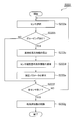
- FIG. 5 is a flow chart showing an example of the correction parameter calculation S222 included in the detection information integration S200 of FIG.
- the correction parameter calculation S222 includes, for example, sensor selection S222a, grouping determination S222b, reference time series information calculation S222c, sensor observable time series information calculation S222d, correction parameter calculation S222e, and end determination S222f. Includes deletion S222g of time series information.
- the arithmetic unit 121 selects, for example, a sensor to be calculated as a correction parameter from a plurality of sensors constituting the external world sensor 110. More specifically, the arithmetic unit 121 selects, for example, the first sensor 111, which is an imaging sensor, in the sensor selection S222a. Next, in the grouping determination S222b, the arithmetic unit 121 determines whether or not the time series information of the detection information grouped in the integrated time series information exists for the selected sensor.
- the arithmetic unit 121 proceeds to the end determination S222f described later when the time series information of the detection information grouped in the integrated time series information does not exist (NO). Further, in the grouping determination S222b, the arithmetic unit 121 proceeds to the calculation S222c of the reference time series information when the time series information of the detection information grouped in the integrated time series information exists (YES). More specifically, in the grouping determination S222b, the arithmetic unit 121 determines whether or not the time series information of the detection information grouped in the integrated time series information exists for the selected first sensor 111.
- the arithmetic unit 121 calculates the time-series information of the observation amount of the sensor as the reference for correction for the selected sensor in the calculation S222c of the reference time-series information as the reference time-series information. More specifically, in the calculation S222c of the reference time series information, the arithmetic unit 121 determines the pixel position as the reference for correction of the first sensor 111, which is the selected imaging device, based on the integrated time series information. The time series information is calculated as the reference time series information.
- the arithmetic unit 121 obtains the time series information of the sensor observation amount at the time of the sensor observation amount based on the time series information which is the time series of the detection information for the selected sensor. Calculated as series information. More specifically, in the calculation S222d of the sensor observation amount time series information, the calculation device 121 determines the pixel position to be corrected for the first sensor 111, which is the selected imaging device, based on the time series information. The time series information is calculated as the sensor observation amount time series information.
- the arithmetic unit 121 calculates the average of the differences between the reference time series information and the sensor observation amount time series information at each time point for the selected sensor, and uses the average of the differences as the correction parameter. It is stored in the storage device 122. More specifically, in the correction parameter calculation S222e, the calculation device 121 describes the pixel positions of the reference time series information and the sensor observation amount time series information at each time point for the first sensor 111, which is the selected image sensor. The average of the differences is calculated, and the average of the differences at the pixel positions is stored in the storage device 122 as a correction parameter.
- the arithmetic unit 121 determines whether or not the calculation of the correction parameters for all the sensors to be selected among the plurality of sensors constituting the external world sensor 110 has been completed. If the calculation of the correction parameters for all the sensors of the selected target has not been completed (NO), the arithmetic unit 121 returns to the sensor selection S222a, and the calculation of the correction parameters for all the sensors of the selected target is completed. If (YES), the process proceeds to deletion S222g of time series information.
- the arithmetic unit 121 deletes the time series information of the sensor stored in the storage device 122 in the time series information storage S209, and deletes the time series information earlier than the predetermined time. Calculation of correction parameter S222 ends. After that, the arithmetic unit 121 stores the correction parameter calculated in the correction parameter calculation S222e in the storage device 122 in the correction parameter storage S211 shown in FIG.
- FIG. 6 is a graph showing an example of time series information of a plurality of sensors included in the external sensor 110 of the vehicle control system 100 of FIG. 7A and 7B are graphs showing the grouping results of the conventional obstacle detection device. 8A and 8B are graphs showing the grouping results of the information integration device 120 of the vehicle control system 100 of FIG.
- the horizontal axis t is time
- the vertical axis x is detection information such as the distance and angle of an object detected by a sensor, for example.
- the solid line and the dotted line are time-series information of the detection information of the same object detected by different types of sensors
- the broken line is another object detected by a sensor of a different type from these sensors. It is the time series information of the detection information of.
- the vehicle control system 100 performs sensor recognition integration that integrates information about an object detected by a plurality of different types of sensors of the external sensor 110, for example, for external sensing of an automobile that performs AD.
- AD travel planning and travel judgment are performed based on the recognition result of an object around the vehicle by the sensor.
- Sensors for detecting objects are diverse, such as radars, cameras, sonars, and laser radars.
- sensors have various conditions such as detection range, detectable object, detection accuracy, and cost. Therefore, it is necessary to combine a plurality of sensors according to the purpose. When combining a plurality of sensors, multiple pieces of information that detect the same object may be generated. It is required to determine that the detection information is information about the same object, integrate them, and output highly accurate integrated detection information. Identifying the detection information of the same object among the detection information of a plurality of sensors in this way is called grouping.
- the conventional obstacle detection device has the obstacle position detected by the first measuring device at each time of t, t + 1, t + 2, ..., T + n with respect to a plurality of time series information as shown in FIG.
- the position of the obstacle detected by the second measuring device overlaps with the position of the obstacle, it is determined that the two obstacles are the same obstacle.
- the observation parameters of the sensor may change over time due to, for example, the effects of vibration and thermal stress.
- the instantaneous value grouping of the conventional obstacle detection device determines whether or not the obstacles detected by the plurality of measuring devices are the same at each time.
- the results may contain errors.
- detection information of a plurality of different objects may be grouped as detection information of the same object, and high-precision grouping is difficult. If the sensor is calibrated in such a situation where the grouping is erroneous, the calibration accuracy of the sensor may decrease.
- time-series grouping based on the temporal transition of a plurality of sensor data enables more accurate grouping than the above-mentioned instantaneous value grouping.
- this conventional behavior recognition device since the sensors are not calibrated, it is not possible to remove the error of the detection information of the object detected by each sensor. Therefore, in the conventional obstacle detection device, it is conceivable to calibrate the sensor by time series grouping instead of the instantaneous value grouping.
- time-series grouping requires time-series information, it takes a longer time than instantaneous value grouping that does not require time-series data.
- the vehicle control system 100 of the present embodiment includes the first sensor 111 and the second sensor 112 constituting the external world sensor 110, the information integration device 120, and the vehicle control device 130. And.
- the first sensor 111 and the second sensor 112 detect an object around the vehicle.
- the information integration device 120 groups the first detection information and the second detection information, which are the detection results of the first sensor 111 and the second sensor 112 that have detected the same object, and outputs the integrated integrated detection information.
- the vehicle control device 130 controls the vehicle based on the integrated detection information.
- the information integration device 120 includes an arithmetic unit 121 and a storage device 122. In the time-series information storage S209 shown in FIG.
- the arithmetic unit 121 stores the first time-series information, which is the time-series information of the first detection information, and the second time-series information, which is the time-series information of the second detection information. It is stored in the storage device 122. Further, the arithmetic unit 121 groups the first time series information and the second time series information when the first sensor 111 and the second sensor 112 detect the same object in the calibration S220 shown in FIG. 1 Calculate the correction parameter of the detection information. Further, the arithmetic unit 121 calculates the correction information obtained by correcting the first detection information by using the correction parameter in the correction S201 shown in FIG. Then, the arithmetic unit 121 outputs the integrated detection information by the instantaneous value grouping using the correction information and the second detection information in the instantaneous value grouping S202 and the integrated update S203 shown in FIG.
- the vehicle control system 100 of the present embodiment executes the instantaneous value grouping S202 by the information integration device 120 by using the correction information corrected for the first detection information of the first sensor 111 during normal driving. be able to.
- the vehicle control system 100 of the present embodiment executes the calibration S220 only when the arithmetic unit 121 of the information integration device 120 determines that the calibration is necessary in the calibration determination S210, and executes the time series grouping in the grouping S221. can do. That is, since the vehicle control system 100 does not execute the time-series grouping during normal driving, there is no need to wait for the time-series information of the sensor detection information to be gathered.
- the arithmetic unit 121 of the information integration device 120 repeats the output of the integration detection information in the integration update S203 at a predetermined cycle, for example, as shown in FIG. Further, the arithmetic unit 121 stores the integrated time series information, which is the time series information of the integrated detection information, in the storage device 122 in the time series of the integrated detection information S204 and the storage of the integrated time series information S205.
- the vehicle control system 100 of the present embodiment can perform grouping S221 using the integrated time series information stored in the storage device 122 when performing calibration S220 by the arithmetic unit 121 of the information integration device 120. it can. Therefore, in the grouping S221, the grouping S221 can be performed using the integrated time series information stored in the storage device 122 without waiting for the integrated detection information to be gathered. Further, the arithmetic unit 121 calculates the prediction information of the detection information and the correction information of the plurality of sensors constituting the external world sensor 110 in the prediction update S207 of the integrated detection information, and the instantaneous value grouping S202 uses the prediction information. Value grouping can be done. As a result, the instantaneous value grouping S202 can be performed more easily and with high accuracy.
- the arithmetic unit 121 of the information integration device 120 calculates a calibration judgment index based on the instability of the instantaneous value grouping in, for example, the calibration judgment S210 shown in FIG. Then, when the calibration determination index becomes equal to or higher than the threshold value, the arithmetic unit 121 performs calibration S220 and calculates the correction parameter.
- the vehicle control system 100 of the present embodiment uses the arithmetic device 121 of the information integration device 120 to check the temporal changes of the observation parameters of the sensors included in the external sensor 110 such as the first sensor 111 as a calibration judgment index. Can be detected based on.
- the correction parameter can be automatically updated according to the change of the observation parameter of the sensor with time, and the instantaneous value grouping S202 by the arithmetic unit 121 can be performed with higher accuracy.
- the arithmetic device 121 of the information integration device 120 has a temporal transition of the first time series information of the first sensor 111 and a temporal transition of the second time series information of the second sensor 112.
- the correction parameters are calculated by grouping based on the transition.
- the arithmetic unit 121 uses the time-series information which is the time-series of the detection information of the plurality of sensors output in the time-series of detection information S208 in the grouping S221.
- the time series grouping shown in 8A and FIG. 8B is performed.
- the arithmetic unit 121 calculates the correction parameter in the correction parameter calculation S222 shown in FIG. With this configuration, more accurate correction parameters can be calculated, and the instantaneous value grouping S202 by the arithmetic unit 121 can be performed with higher accuracy.
- a vehicle control system 100 capable of grouping a plurality of detection results of the same object detected by a plurality of sensors with high accuracy and in a short time. it can.
- the vehicle control system 100 according to the second embodiment of the present disclosure will be described with reference to FIGS. 1 to 8 of the above-described first embodiment.
- the vehicle control system 100 of the present embodiment has a different configuration of the information integration device 120 from the above-described first embodiment. Since the other points of the vehicle control system 100 of the present embodiment are the same as those of the vehicle control system 100 according to the first embodiment, the same reference numerals are given to the same parts and the description thereof will be omitted.
- the arithmetic unit 121 of the information integration device 120 has the following features.
- the result of the instantaneous value grouping S202 using the latest correction information of the first sensor 111 and the second detection information of the second sensor 112 is an instantaneous value using the past correction information and the second detection information.
- the calibration judgment index is calculated based on the number of different information between the result of the latest instantaneous value grouping S202 and the result of the past instantaneous value grouping S202. Then, the arithmetic unit 121 calculates the correction parameter when the calibration determination index becomes equal to or higher than the threshold value.
- FIG. 9 is a flow chart of the calibration determination S210 by the arithmetic unit 121 of the present embodiment.
- the calibration determination S210 includes, for example, a detection information selection S210a, a grouping release addition S210b, a grouping additional addition S210c, a selection end determination S210d, a binary information output setting S210e, and an index initialization S210f.
- the arithmetic unit 121 selects one of the integrated detection information grouped by the previous and latest instantaneous value grouping S202 in the detection information selection S210a. In the grouping release addition S210b, the arithmetic unit 121 excludes the grouping target by the latest instantaneous value grouping S202 among the latest detection information of a plurality of sensors integrated into one integrated detection information in the previous instantaneous value grouping S202. The number of detected information is added to the calibration judgment index.
- the arithmetic unit 121 includes the detection information targeted for grouping in the latest instantaneous value grouping S202 among the latest detection information of a plurality of sensors that were not grouped in the previous instantaneous value grouping S202. Add the number to the calibration judgment index. The arithmetic unit 121 determines in the selection end determination S210d whether or not all of the integrated detection information grouped by the previous and latest instantaneous value grouping S202 has been selected.
- the arithmetic unit 121 returns to the detection information selection S210a when the selection end determination S210d does not complete the selection of all the integrated detection information grouped by the previous and latest instantaneous value grouping S202 (NO).
- the arithmetic unit 121 proceeds to the binary information output setting S210e when the selection of all the integrated detection information grouped by the previous and latest instantaneous value grouping S202 is completed in the selection end determination S210d (YES).
- the arithmetic unit 121 determines in the binary information output setting S210e whether or not the calibration determination index is equal to or higher than the threshold value, and sets, for example, true and false binary information as an output. Specifically, the arithmetic unit 121 sets false as an output when the calibration judgment index is less than the threshold value in the binary information output setting S210e, and is true when the calibration judgment index is greater than or equal to the threshold value. Is set as an output, and the process proceeds to exponential initialization S210f. When true is set as an output in the binary information output setting SS210e, the arithmetic unit 121 initializes the calibration judgment index to zero in the index initialization S210f and outputs the true of the true / false binary information. The calibration determination S210 is terminated.
- the correction parameter when the correction parameter is not appropriate in the information integration device 120, the correction parameter is updated to an appropriate value earlier than the vehicle control system 100 according to the first embodiment. Can be done.
- the time until the correction parameter is updated can be extended as compared with the vehicle control system 100 according to the first embodiment. As a result, the frequency of the calibration determination S210 by the arithmetic unit 121 can be reduced, and the processing time can be reduced.
- the vehicle control system 100 according to the second embodiment of the present disclosure will be described with reference to FIGS. 1 to 8 of the above-described first embodiment.
- the vehicle control system 100 of the present embodiment has a different configuration of the information integration device 120 from the above-described first embodiment. Since the other points of the vehicle control system 100 of the present embodiment are the same as those of the vehicle control system 100 according to the first embodiment, the same reference numerals are given to the same parts and the description thereof will be omitted.
- the arithmetic unit 121 of the information integration device 120 is corrected by grouping based on the time series distance of the first time series information of the first sensor 111 and the second time series information of the second sensor 112. Calculate the parameters. That is, in the present embodiment, the arithmetic device 121 of the information integration device 120 uses the first time series information instead of the grouping S221 that uses the time transition of the first time series information and the time transition of the second time series information. Grouping S221 based on the time series distance of the second time series information is performed.
- the arithmetic unit 121 integrates time-series information, which is a time-series of detection information of a plurality of sensors, by clustering, which is one of the unsupervised learning methods, in the grouping S221.
- FIG. 10 is a flow chart of grouping S221 in calibration S220 by the arithmetic unit 121 of the present embodiment.
- the grouping S221 of the calibration S220 includes, for example, priority queuing S221a, time average Mahalanobis distance calculation S221b, minimum value output S221c, minimum value determination S221d, time series information integration S221e, and time average Mahalanobis distance update. Includes S221f and.
- the arithmetic unit 121 creates an empty priority queue in the storage device 122 in the priority queue creation S221a.
- a priority queue is, for example, a collection in which the minimum value can be retrieved preferentially.
- the arithmetic unit 121 calculates the time average Mahalanobis distance between the time series information of the plurality of sensors using the above equation (2), and adds it to the prioritized queue of the storage device 122. To do.
- the arithmetic unit 121 extracts the combination of the time series information of the sensor that minimizes the average Mahalanobis distance when output from the priority queuing in the minimum value output S221c.
- the arithmetic unit 121 determines whether or not the hourly average Mahalanobis distance of the combination of the extracted time series information is equal to or less than the threshold value.
- the arithmetic unit 121 ends the grouping S221 when the hourly average Mahalanobis distance exceeds the threshold value in the minimum value determination S221d (NO).
- the hourly average Mahalanobis distance is equal to or less than the threshold value in the minimum value determination S221d (YES)
- the arithmetic unit 121 proceeds to the time series information integration S221e.
- the arithmetic unit 121 integrates the time series information of the sensor whose time average Mahalanobis distance is equal to or less than the threshold value in the time series information integration S221e.
- the arithmetic unit 121 updates the hourly average Mahalanobis distance between the time series information of the plurality of sensors in the hourly average Mahalanobis distance update S221f. Further, the arithmetic unit 121 deletes the time average Mahalanobis distance related to the combination of the time series information of the sensors before integration from the priority queue, and waits for the time average Mahalanobis distance related to the time series information after integration with priority. Add to the matrix and return to the minimum value output S221c.
- the integrated time series information is not used in the grouping S221 of the calibration S220 by the arithmetic unit 121 of the information integration device 120.
- the instantaneous value grouping S202 even if an erroneous grouping is performed, it is possible to prevent the erroneous grouping result from propagating to the integrated time series information storage S205 and the correction parameter storage S211. Therefore, the influence of the error can be eliminated in the correction parameter calculation S222, and the detection information of the sensor can be corrected with high accuracy in the correction S201.
- Vehicle control system 111 First sensor 112 Second sensor 120 Information integration device 121 Arithmetic logic unit 122 Storage device 130 Vehicle control device
Landscapes
- Engineering & Computer Science (AREA)
- Radar, Positioning & Navigation (AREA)
- Remote Sensing (AREA)
- Physics & Mathematics (AREA)
- General Physics & Mathematics (AREA)
- Automation & Control Theory (AREA)
- Mechanical Engineering (AREA)
- Transportation (AREA)
- Computer Networks & Wireless Communication (AREA)
- Theoretical Computer Science (AREA)
- Multimedia (AREA)
- Human Computer Interaction (AREA)
- Computer Vision & Pattern Recognition (AREA)
- Mathematical Physics (AREA)
- Electromagnetism (AREA)
- Health & Medical Sciences (AREA)
- Artificial Intelligence (AREA)
- Computing Systems (AREA)
- Databases & Information Systems (AREA)
- Evolutionary Computation (AREA)
- General Health & Medical Sciences (AREA)
- Medical Informatics (AREA)
- Software Systems (AREA)
- Traffic Control Systems (AREA)
- Radar Systems Or Details Thereof (AREA)
Abstract
Description
以下では、まず、図1および図2を参照して、本開示の実施形態1に係る車両制御システム100の構成を説明し、次に、図3を参照して、情報統合装置120による検知情報統合S200の流れを説明する。
図1は、本実施形態の車両制御システム100の構成例を示すブロック図である。車両制御システム100は、たとえば自動車などの車両に搭載され、車両の先進運転支援システム(ADAS)や自動運転(AD)システムを構成する。車両制御システム100は、たとえば、外界センサ110と、情報統合装置120と、車両制御装置130と、を備えている。また、車両制御システム100は、たとえば、車両センサ140と、測位システム150と、地図ユニット160と、アクチュエータ170とを備えてもよい。
次に、図1に示す情報統合装置120による処理に含まれる検知情報統合S200について、詳細に説明する。図3は、図2に示す情報統合装置120の処理に含まれる検知情報統合S200の詳細を示すフロー図である。


次に、前述の実施形態1の図1から図8を援用し、図9を参照して本開示の実施形態2に係る車両制御システム100を説明する。本実施形態の車両制御システム100は、情報統合装置120の構成が前述の実施形態1と異なっている。本実施形態の車両制御システム100のその他の点は、前述の実施形態1に係る車両制御システム100と同様であるので、同様の部分には同一の符号を付して説明を省略する。
次に、前述の実施形態1の図1から図8を援用し、図10を参照して本開示の実施形態2に係る車両制御システム100を説明する。本実施形態の車両制御システム100は、情報統合装置120の構成が前述の実施形態1と異なっている。本実施形態の車両制御システム100のその他の点は、前述の実施形態1に係る車両制御システム100と同様であるので、同様の部分には同一の符号を付して説明を省略する。
111 第1センサ
112 第2センサ
120 情報統合装置
121 演算装置
122 記憶装置
130 車両制御装置
Claims (6)
- 車両の周囲の物体を検知する第1センサおよび第2センサと、同一の物体を検知した前記第1センサと前記第2センサの検知結果である第1検知情報と第2検知情報をグルーピングして統合された統合検知情報を出力する情報統合装置と、前記統合検知情報に基づいて車両を制御する車両制御装置と、を備えた車両制御システムであって、
前記情報統合装置は、演算装置と記憶装置を含み、
前記演算装置は、
前記第1検知情報の時系列情報である第1時系列情報と前記第2検知情報の時系列情報である第2時系列情報とを前記記憶装置に記憶させ、
前記第1センサと前記第2センサが同一の物体を検知したときの前記第1時系列情報と前記第2時系列情報とをグルーピングして前記第1検知情報の補正パラメータを算出し、
前記補正パラメータを用いて前記第1検知情報を補正した補正情報を算出し、
前記補正情報と前記第2検知情報とを用いた瞬時値グルーピングによって前記統合検知情報を出力することを特徴とする
車両制御システム。 - 前記演算装置は、
前記統合検知情報の出力を所定の周期で繰り返し、前記統合検知情報の時系列情報である統合時系列情報を前記記憶装置に記憶させることを特徴とする
請求項1に記載の車両制御システム。 - 前記演算装置は、前記瞬時値グルーピングの不安定性に基づく校正判断指数を算出し、前記校正判断指数がしきい値以上になったときに前記補正パラメータを算出することを特徴とする
請求項2に記載の車両制御システム。 - 前記演算装置は、
新たな前記補正情報と前記第2検知情報とを用いたグルーピングの結果が過去の前記補正情報と前記第2検知情報とを用いたグルーピングの結果と異なる場合に、前記新たなグルーピング結果と前記過去のグルーピング結果との間の異なる情報の個数に基づいて校正判断指数を算出し、前記校正判断指数がしきい値以上になったときに前記補正パラメータを算出することを特徴とする
請求項2に記載の車両制御システム。 - 前記演算装置は、前記第1時系列情報の時間的推移と前記第2時系列情報の時間的推移とに基づくグルーピングによって前記補正パラメータを算出することを特徴とする
請求項2に記載の車両制御システム。 - 前記演算装置は、前記第1時系列情報と前記第2時系列情報の時系列距離に基づくグルーピングによって前記補正パラメータを算出することを特徴とする
請求項2に記載の車両制御システム。
Priority Applications (3)
| Application Number | Priority Date | Filing Date | Title |
|---|---|---|---|
| US17/605,339 US11891086B2 (en) | 2019-05-13 | 2020-04-28 | Vehicle control system |
| JP2021519364A JP7285923B2 (ja) | 2019-05-13 | 2020-04-28 | 車両制御システム |
| DE112020001776.1T DE112020001776B4 (de) | 2019-05-13 | 2020-04-28 | Fahrzeugsteuersystem |
Applications Claiming Priority (2)
| Application Number | Priority Date | Filing Date | Title |
|---|---|---|---|
| JP2019-090353 | 2019-05-13 | ||
| JP2019090353 | 2019-05-13 |
Publications (1)
| Publication Number | Publication Date |
|---|---|
| WO2020230619A1 true WO2020230619A1 (ja) | 2020-11-19 |
Family
ID=73290021
Family Applications (1)
| Application Number | Title | Priority Date | Filing Date |
|---|---|---|---|
| PCT/JP2020/018068 Ceased WO2020230619A1 (ja) | 2019-05-13 | 2020-04-28 | 車両制御システム |
Country Status (4)
| Country | Link |
|---|---|
| US (1) | US11891086B2 (ja) |
| JP (1) | JP7285923B2 (ja) |
| DE (1) | DE112020001776B4 (ja) |
| WO (1) | WO2020230619A1 (ja) |
Families Citing this family (1)
| Publication number | Priority date | Publication date | Assignee | Title |
|---|---|---|---|---|
| US11572082B2 (en) * | 2020-10-27 | 2023-02-07 | Automotive Research & Testing Center | Driving risk assessment and control decision-making method for autonomous vehicle |
Citations (4)
| Publication number | Priority date | Publication date | Assignee | Title |
|---|---|---|---|---|
| JP2010249613A (ja) * | 2009-04-14 | 2010-11-04 | Toyota Motor Corp | 障害物認識装置及び車両制御装置 |
| WO2016027652A1 (ja) * | 2014-08-18 | 2016-02-25 | 株式会社デンソー | 物体認識装置 |
| WO2019039279A1 (ja) * | 2017-08-22 | 2019-02-28 | ソニー株式会社 | 信号処理装置、および信号処理方法、プログラム、移動体、並びに、信号処理システム |
| US20190120955A1 (en) * | 2017-10-20 | 2019-04-25 | Texas Instruments Incorporated | System and method for camera radar fusion |
Family Cites Families (11)
| Publication number | Priority date | Publication date | Assignee | Title |
|---|---|---|---|---|
| JP4070437B2 (ja) | 2001-09-25 | 2008-04-02 | ダイハツ工業株式会社 | 前方車両認識装置及び認識方法 |
| JP2010276529A (ja) | 2009-05-29 | 2010-12-09 | Panasonic Corp | 物体同定装置および物体同定方法 |
| WO2012068064A1 (en) | 2010-11-15 | 2012-05-24 | Image Sensing Systems, Inc. | Hybrid traffic sensor system and associated method |
| GB201303076D0 (en) | 2013-02-21 | 2013-04-10 | Isis Innovation | Generation of 3D models of an environment |
| US9563808B2 (en) | 2015-01-14 | 2017-02-07 | GM Global Technology Operations LLC | Target grouping techniques for object fusion |
| JP6523050B2 (ja) | 2015-06-02 | 2019-05-29 | 日立建機株式会社 | 鉱山用作業機械 |
| JP6611257B2 (ja) | 2016-07-19 | 2019-11-27 | 日本電信電話株式会社 | 行動認識装置、および、行動認識方法 |
| WO2018212346A1 (ja) * | 2017-05-18 | 2018-11-22 | パイオニア株式会社 | 制御装置、走査システム、制御方法、およびプログラム |
| CN111417869B (zh) * | 2017-11-20 | 2024-08-20 | 三菱电机株式会社 | 障碍物识别装置及障碍物识别方法 |
| DE102018220024B3 (de) * | 2018-11-22 | 2020-03-12 | Audi Ag | Verfahren zur Fusion von Sensordaten von mehreren Sensoren und Fusionsvorrichtung zum Fusionieren von Sensordaten von mehreren Sensoren |
| US11698440B2 (en) * | 2019-04-02 | 2023-07-11 | Universal City Studios Llc | Tracking aggregation and alignment |
-
2020
- 2020-04-28 JP JP2021519364A patent/JP7285923B2/ja active Active
- 2020-04-28 WO PCT/JP2020/018068 patent/WO2020230619A1/ja not_active Ceased
- 2020-04-28 DE DE112020001776.1T patent/DE112020001776B4/de active Active
- 2020-04-28 US US17/605,339 patent/US11891086B2/en active Active
Patent Citations (4)
| Publication number | Priority date | Publication date | Assignee | Title |
|---|---|---|---|---|
| JP2010249613A (ja) * | 2009-04-14 | 2010-11-04 | Toyota Motor Corp | 障害物認識装置及び車両制御装置 |
| WO2016027652A1 (ja) * | 2014-08-18 | 2016-02-25 | 株式会社デンソー | 物体認識装置 |
| WO2019039279A1 (ja) * | 2017-08-22 | 2019-02-28 | ソニー株式会社 | 信号処理装置、および信号処理方法、プログラム、移動体、並びに、信号処理システム |
| US20190120955A1 (en) * | 2017-10-20 | 2019-04-25 | Texas Instruments Incorporated | System and method for camera radar fusion |
Also Published As
| Publication number | Publication date |
|---|---|
| DE112020001776T5 (de) | 2022-01-27 |
| DE112020001776B4 (de) | 2025-11-06 |
| JPWO2020230619A1 (ja) | 2020-11-19 |
| US11891086B2 (en) | 2024-02-06 |
| US20220227386A1 (en) | 2022-07-21 |
| JP7285923B2 (ja) | 2023-06-02 |
Similar Documents
| Publication | Publication Date | Title |
|---|---|---|
| US20230079730A1 (en) | Control device, scanning system, control method, and program | |
| JP7078909B2 (ja) | 車両制御装置及び車両制御用コンピュータプログラム | |
| EP3644294B1 (en) | Vehicle information storage method, vehicle travel control method, and vehicle information storage device | |
| CN115427759B (zh) | 地图信息校正方法、驾驶辅助方法及地图信息校正装置 | |
| RU2645388C2 (ru) | Устройство определения неправильного распознавания | |
| JP2020053094A (ja) | 道路の車線識別子を決定する方法及び装置 | |
| WO2018181974A1 (ja) | 判定装置、判定方法、及び、プログラム | |
| JP2025065215A (ja) | 地図作成装置、制御方法、プログラム及び記憶媒体 | |
| JP7167732B2 (ja) | 地図情報システム | |
| CN115071701B (zh) | 车辆控制装置及车辆控制方法 | |
| JP6521753B2 (ja) | 車両の測位システム | |
| CN112498347A (zh) | 用于实时横向控制和转向致动评估的方法和装置 | |
| US20230150514A1 (en) | Adaptive rationalizer for vehicle perception systems toward robust automated driving control | |
| JP7808722B2 (ja) | 情報処理装置、地図データ生成装置、方法及びプログラム | |
| WO2016194168A1 (ja) | 走行制御装置及び方法 | |
| JP7711727B2 (ja) | 車両制御装置、車両制御用コンピュータプログラム及び車両制御方法 | |
| JP7351283B2 (ja) | ドライバへの通知装置 | |
| JP4899657B2 (ja) | 道路形状取得装置 | |
| CN115667849A (zh) | 用于求取车辆的起始位姿的方法 | |
| JP7147448B2 (ja) | 地図情報システム | |
| JP7285923B2 (ja) | 車両制御システム | |
| JP7812476B2 (ja) | 測定装置、測定方法、プログラム、及び、記憶媒体 | |
| JP7378591B2 (ja) | 走行経路生成装置 | |
| US20240010242A1 (en) | Signal processing device and signal processing method | |
| CN116222587B (zh) | 位置精度判定装置、存储介质以及判定方法 |
Legal Events
| Date | Code | Title | Description |
|---|---|---|---|
| 121 | Ep: the epo has been informed by wipo that ep was designated in this application |
Ref document number: 20806490 Country of ref document: EP Kind code of ref document: A1 |
|
| ENP | Entry into the national phase |
Ref document number: 2021519364 Country of ref document: JP Kind code of ref document: A |
|
| WWE | Wipo information: entry into national phase |
Ref document number: 112020001776 Country of ref document: DE |
|
| WWP | Wipo information: published in national office |
Ref document number: 112020001776 Country of ref document: DE |
|
| 122 | Ep: pct application non-entry in european phase |
Ref document number: 20806490 Country of ref document: EP Kind code of ref document: A1 |
|
| WWG | Wipo information: grant in national office |
Ref document number: 112020001776 Country of ref document: DE |