WO2020230545A1 - シール装置 - Google Patents
シール装置 Download PDFInfo
- Publication number
- WO2020230545A1 WO2020230545A1 PCT/JP2020/017171 JP2020017171W WO2020230545A1 WO 2020230545 A1 WO2020230545 A1 WO 2020230545A1 JP 2020017171 W JP2020017171 W JP 2020017171W WO 2020230545 A1 WO2020230545 A1 WO 2020230545A1
- Authority
- WO
- WIPO (PCT)
- Prior art keywords
- cap
- rotating shaft
- lip seal
- seal
- inner diameter
- Prior art date
- Legal status (The legal status is an assumption and is not a legal conclusion. Google has not performed a legal analysis and makes no representation as to the accuracy of the status listed.)
- Ceased
Links
Images


Classifications
-
- F—MECHANICAL ENGINEERING; LIGHTING; HEATING; WEAPONS; BLASTING
- F16—ENGINEERING ELEMENTS AND UNITS; GENERAL MEASURES FOR PRODUCING AND MAINTAINING EFFECTIVE FUNCTIONING OF MACHINES OR INSTALLATIONS; THERMAL INSULATION IN GENERAL
- F16J—PISTONS; CYLINDERS; SEALINGS
- F16J15/00—Sealings
- F16J15/16—Sealings between relatively-moving surfaces
- F16J15/32—Sealings between relatively-moving surfaces with elastic sealings, e.g. O-rings
- F16J15/3204—Sealings between relatively-moving surfaces with elastic sealings, e.g. O-rings with at least one lip
- F16J15/3232—Sealings between relatively-moving surfaces with elastic sealings, e.g. O-rings with at least one lip having two or more lips
-
- F—MECHANICAL ENGINEERING; LIGHTING; HEATING; WEAPONS; BLASTING
- F16—ENGINEERING ELEMENTS AND UNITS; GENERAL MEASURES FOR PRODUCING AND MAINTAINING EFFECTIVE FUNCTIONING OF MACHINES OR INSTALLATIONS; THERMAL INSULATION IN GENERAL
- F16J—PISTONS; CYLINDERS; SEALINGS
- F16J15/00—Sealings
- F16J15/44—Free-space packings
- F16J15/447—Labyrinth packings
Definitions
- the present invention relates to a sealing device.
- a lip-type shaft sealing device is used to obtain the desired sealing performance by using the pressure of the fluid.
- a lip-type sealing device used in a compressor that constitutes a car air conditioner has a sliding portion of a lip seal formed of elastic rubber that is slidably contacted with a shaft so that the refrigerant inside the machine is brought into the atmosphere side. Prevents leakage.
- Patent Document 1 includes first to third lip seals in order from the inside of the machine, and the first lip seal and the second lip seal are directed from the outer diameter to the inner diameter.
- the third lip seal extends from the outer diameter to the inner diameter toward the atmosphere. Further, the first to third lip seals are integrated on the outer diameter side.
- the first lip seal and the second lip seal axially seal the refrigerant inside the machine, while the third lip seal prevents the outside air from entering the inside of the machine from the atmosphere side. It has become. Therefore, even if the inside of the machine becomes negative pressure during the operation of the compressor, the suction of outside air can be suppressed, and the air conditioner can be operated without lowering the freezing efficiency.
- JP-A-2018-17161 (Pages 6-8, Fig. 2)
- the present invention has been made by paying attention to such a problem, and provides a sealing device capable of suppressing the ingress of outside air from the atmosphere side to the inside of the machine and relatively rotating the rotating shaft body with a small torque. It is a thing.
- the sealing device of the present invention A sealing device that seals an annular gap between a rotating shaft body that rotates relatively and a housing by a first lip seal.
- a cap seal having a ring-shaped thin plate at least on the inner diameter side is provided, and the inner diameter of the cap seal is the same as the outer diameter of the rotating shaft body or larger than the rotating shaft body.
- the inner surface of the cap seal may be formed parallel to the outer peripheral surface of the rotating shaft body in the axial direction. According to this, the gap between the cap seal and the rotating shaft body is formed so as to extend in the axial direction, and since the gap is long in the axial direction, the intrusion of outside air from the atmosphere side to the inside of the machine can be reliably suppressed.
- the inner diameter of the cap seal may be larger than the outer diameter of the rotating shaft body. According to this, since it is difficult for the cap seal to come into contact with the rotating shaft body that rotates relative to each other, the rotating shaft body can be relatively rotated with less torque.
- the cap seal may be arranged closer to the atmosphere than the first lip seal. According to this, the cap seal can prevent the air and the dust on the atmospheric side from entering the first lip seal.
- the second lip seal may be arranged closer to the atmosphere than the cap seal. According to this, between the first lip seal and the second lip seal located between the inside of the machine and the atmosphere side, the first lip seal-cap seal section and the cap seal-second lip seal section 2 by the cap seal. Since it is divided into two sections and the pressure changes stepwise in the two sections, it is possible to suppress the load due to the pressure of the fluid to be sealed on the second lip seal.
- the cap seal may be arranged inside the machine more than the first lip seal. According to this, the pressure fluctuation of the fluid to be sealed inside the machine can be alleviated by the cap seal, and the load due to the momentary pressure fluctuation on the first lip seal can be suppressed.
- the cap seal may be made of PTFE (polytetrafluoroethylene). According to this, since PTFE has low frictional properties, the frictional resistance between the cap seal and the rotating shaft can be reduced. Further, when the cap seal is arranged closer to the atmosphere than the first lip seal, it is more effective because the cap seal is arranged at a place where the fluid to be sealed is difficult to be supplied and the lubrication is poor.
- PTFE polytetrafluoroethylene
- the front side of the paper surface in FIG. 1 is the front side, and the vertical and horizontal directions when viewed from the front side are used as a reference.
- the left side is the atmosphere side A
- the right side is the inside L of the machine
- the upper side is the outer diameter side
- the lower side is the inner diameter side. It is explained as.
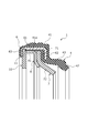
- the sealing device 1 includes a first lip seal 4, a second lip seal 7, a cap 10 as a cap seal, and the first lip seal 4, the second lip seal 7, and the cap 10. It is mainly composed of a backup ring 8 and a skeleton ring 6 which play a role of strength assistance and movement regulation, and a sealing device 1 which unitizes these is mounted in a housing 3 and a first lip seal 4 and a second.
- the lip seal 7 seals the annular gap between the rotating shaft 2 as the rotating shaft and the housing 3 to prevent the refrigerant inside the machine from leaking to the atmosphere side A (see FIG. 2).
- the first lip seal 4, the second lip seal 7, and the cap 10 are arranged in order from the inside L of the machine to the atmosphere side A. Further, as the refrigerant inside the machine L, alternative chlorofluorocarbons such as HCFC (hydrochlorofluorocarbon) and HFC (hydrofluorocarbon), carbon dioxide gas and the like are used.
- HCFC hydrochlorofluorocarbon
- HFC hydrofluorocarbon
- the first lip seal 4 is formed of hydrogenated nitrile rubber, nitrile rubber, fluorine rubber, ethylene propylene rubber, etc., and has a main body 41 on the outer diameter side and a leg 43 extending from the main body 41 to the inside L of the machine. It is mainly composed of a tip portion 42 located on the inner diameter side of the leg portion 43 and continuous with the leg portion 43.
- a metal skeleton ring 6 having a substantially U-shaped cross-sectional view is internally provided in a main body portion 41 having a substantially U-shaped cross-sectional view, and the skeleton ring 6 has a base portion 61 extending in the axial direction and the base portion.
- the main body 41 is formed with a fitting recess 41a by a horizontal portion extending in the axial direction and a pair of hanging portions extending toward the inner diameter side from each end of the machine inside L and the atmosphere side A of the horizontal portion. .. Further, the sliding portion 42a formed on the inner diameter side of the tip portion 42 slides with respect to the rotating shaft 2 (see FIG. 2).
- the second lip seal 7 is a member made of PTFE (polytetrafluoroethylene), and includes a root portion 71 extending in the radial direction and an extending portion 72. Further, the extension portion 72 extends to the inside L of the machine, and the sliding portion 72a formed on the inner diameter side of the extension portion 72 slides with respect to the rotating shaft 2 (see FIG. 2). ..
- PTFE polytetrafluoroethylene
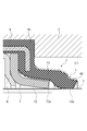
- the cap 10 is a member made of PTFE and has a ring shape having a rectangular cross section, and an inner diameter surface 12 as an inner surface thereof is formed parallel to the outer peripheral surface of the axial rotation shaft 2. Further, since the inner diameter of the cap 10 is slightly larger than the outer diameter of the rotating shaft 2, the inner diameter surface 12 is not in contact with the rotating shaft 2, and there is a slight annular gap between the cap 10 and the rotating shaft 2. 13 is formed (see FIG. 2). At this time, the radial dimension ⁇ of the gap 13 is smaller than the radial dimension R of the cap 10 ( ⁇ ⁇ R), preferably smaller than 1/5 of the radial dimension R of the cap 10 ( ⁇ ⁇ R / 5).
- the radial dimension ⁇ of the gap 13 is smaller than the axial dimension W of the sliding portion 42a of the first lip seal 4 ( ⁇ ⁇ W), preferably 1/2 of the axial dimension W of the sliding portion 42a. It is smaller than ( ⁇ ⁇ W / 2), and more preferably smaller than 1/4 of the axial dimension W of the sliding portion 42a ( ⁇ ⁇ W / 4) (see FIG. 2). Since the inner diameter surface 12 does not come into contact with the rotating shaft 2 and is not tightened in the inner diameter direction, the sealing device 1 can be easily mounted in the housing 3.
- the root portion 71 of the second lip seal 7, the outer diameter portion 81 extending in the axial direction of the backup ring 8, and the root portion 11 of the cap 10 are housed in the fitting recess 41a of the main body portion 41 of the first lip seal 4. It is sandwiched in the axial direction by the main body 41 and the skeleton ring 6. In this way, the first lip seal 4, the second lip seal 7, the backup ring 8, and the cap 10 are unitized to form the seal device 1, and the seal device 1 is mounted in the housing 3. (See Fig. 2).
- the leg portion 43 of the first lip seal 4 is elastically restored by being bent toward the inside L of the machine.
- the leg portion 43 and the sliding portion 42a are pressed against the rotating shaft 2 in the inner diameter direction and toward the atmosphere side A by the force and the pressure of the refrigerant inside the machine L, and the tip portion 42 is partially crushed.
- the sliding portion 42a of the first lip seal 4 is in sliding contact. According to this, since the first lip seal 4 seals between the rotating shaft 2 and the housing 3, it is possible to suppress leakage of the refrigerant to the atmosphere side A.
- the extension portion 72 of the second lip seal 7 also has an inner diameter of the extension portion 72 due to the elastic restoring force due to being bent toward the inside L of the machine and the pressure of the refrigerant passing through a part of the first lip seal 4. Pressed in the direction and toward the atmosphere side A, the sliding portion 72a of the second lip seal 7 is in sliding contact with the rotating shaft 2. According to this, since the second lip seal 7 is arranged in addition to the first lip seal 4, leakage of the refrigerant to the atmosphere side A can be reliably suppressed.
- the outside air on the atmospheric side A tries to enter the machine inside L due to the differential pressure, but it is formed between the inner diameter surface 12 of the cap 10 and the outer peripheral surface of the rotating shaft 2. Since the width in the radial direction is narrow in the gap 13, the inflow resistance of the fluid is generated by the throttle effect, so that the inflow of the outside air can be suppressed. In addition, the inflow of outside air can also be suppressed by the circumferential flow of gas in the gap 13 and its vicinity generated by the inertia caused by the rotation of the rotating shaft 2. Further, since the gap 13 is formed in the axial direction of the cap 10, in other words, in the width direction, the above two effects can be sufficiently exerted. Therefore, the inflow of outside air can be suppressed by the cap 10 even if the lip seal extending from the outer diameter to the inner diameter toward the atmosphere side A is not provided.
- the first lip seal 4 is deformed so as to slightly rise in the outer diameter direction, but the sliding portion 42a is in contact with the rotating shaft 2 and slides in a sealed state. Can be maintained. Further, since the second lip seal 7 is arranged on the cap 10 side of the first lip seal 4, the leakage of the refrigerant to the atmosphere side A can be reliably suppressed.
- the gap 13 is formed between the inner diameter surface 12 of the cap 10 and the outer peripheral surface of the rotating shaft 2, it is difficult for the cap 10 to come into contact with the rotating shaft 2 which rotates relative to the rotating shaft 2, and the frictional resistance is small.
- the rotating shaft 2 can be activated by, and the power load of the device can be reduced.
- the sealing device 1 since the sealing device 1 has a ring shape having a rectangular cross section and has a cap 10 having an inner diameter larger than that of the rotating shaft 2, it is formed between the cap 10 and the rotating shaft 2. Due to the throttle effect in the narrow gap 13, the intrusion of outside air from the atmosphere side A to the inside L of the machine can be suppressed. Further, since the cap 10 is hard to come into contact with the rotating shaft 2 that rotates relative to each other and the frictional resistance is small, the rotating shaft 2 can be started with a small torque.
- the inner diameter surface 12 of the cap 10 is formed parallel to the outer peripheral surface of the axial rotation shaft 2. According to this, the gap 13 between the cap 10 and the rotating shaft 2 is formed so as to extend in the axial direction, and the gap 13 is long in the axial direction, so that the outside air can surely enter from the atmosphere side A to the inside L of the machine. Can be suppressed.
- the cap 10 since the cap 10 is arranged closer to the atmosphere side A than the first lip seal 4, the cap 10 can prevent the atmosphere and dust on the atmosphere side A from entering the first lip seal 4.
- the cap 10 is made of PTFE and the PTFE has low frictional properties, the frictional resistance between the cap 10 and the rotating shaft 2 can be reduced. Further, when the cap 10 is arranged closer to the atmosphere side A than the first lip seal 4, the cap 10 is arranged at a position where the refrigerant is difficult to be supplied and the lubrication is poor, which is more effective.
- the cap 10 has a rectangular cross section and does not abut on the rotating shaft 2, the mounting length in the axial direction can be shortened, and the configuration of the sealing device can be reduced.
- a modified example 1 of the first embodiment will be described.
- the same components as those shown in the above embodiment are designated by the same reference numerals, and duplicate description will be omitted.
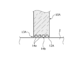
- the inner diameter of the cap 10A is slightly larger than the outer diameter of the rotating shaft 2, and a gap 13A is formed.
- a plurality of annular concave grooves 14a are provided on the inner diameter surface 12A of the cap 10A, and an annular space 14b is formed between the plurality of annular concave grooves 14a and the outer peripheral surface of the rotating shaft 2. According to this, since the inner diameter surface 12A of the cap 10A has a labyrinth structure, the inflow of fluid can be suppressed more than the flat surface.
- a modified example 2 of the first embodiment will be described.
- the same components as those shown in the above embodiment are designated by the same reference numerals, and duplicate description will be omitted.
- the inner diameter side of the cap 10B is tapered, that is, the axial width is narrowed toward the inner diameter, and the inner diameter portion forms the inner diameter surface 12B.
- the inner diameter of the cap 10B is larger than the outer diameter of the rotating shaft 2, and a gap 13B is formed between the inner diameter surface 12B and the outer peripheral surface of the rotating shaft 2.
- the cross-sectional shape of the cap does not have to be rectangular as shown in the first embodiment.
- the sealing device 101 includes a first lip seal 104, a second lip seal 107, a cap 110, and strength assistance of the first lip seal 104, the second lip seal 107, and the cap 110.
- the first backup ring 105, the second backup ring 108, the L-shaped rings 109a, 109b, and the skeleton ring 106 which play the role of movement regulation, are mainly composed of the seal device 101, which is a unitized seal device 101, inside the housing 3. It is attached to.
- the first lip seal 104, the cap 110, and the second lip seal 107 are arranged in order from the inside L of the machine to the atmosphere side A.
- the first lip seal 104 and the second lip seal 107 seal between the rotating shaft 2 and the housing 3 in the same manner as in the first embodiment. Further, as described in the first embodiment, the cap 110 is moved from the atmosphere side A to the inside L of the machine by forming a gap 113 between the inner diameter surface 112 and the outer peripheral surface of the rotating shaft 2. It is possible to suppress the ingress of outside air and the ingress of refrigerant from the inside L of the machine to the atmosphere side A.
- the cap 110 is arranged between the first lip seal 104 and the second lip seal 107, the first lip seal located between the machine inside L and the atmosphere side A.
- the section between 104 and the second lip seal 107 is divided into two sections, the first lip seal 104-cap 110 section and the cap 110-second lip seal 107 section, by the cap 110, and the pressure is gradually applied in the two sections. Change will occur. At this time, the load due to the pressure of the refrigerant on the second lip seal 107 can be suppressed as compared with the case where the cap 110 is not arranged between the first lip seal 104 and the second lip seal 107.
- Example 1 the sealing device according to the third embodiment will be described with reference to FIG. 7. It should be noted that the same configuration as in Examples 1 and 2 and the duplicate description will be omitted. Modifications 1 and 2 of Example 1 may be applied to this example.
- the sealing device 201 includes a first lip seal 204, a second lip seal 207, a cap 210, and strength assistance of the first lip seal 204, the second lip seal 207, and the cap 210.
- the sealing device 201 which is mainly configured and unitized by these, is mounted in the housing 3. Further, the cap 210, the first lip seal 204, and the second lip seal 207 are arranged in order from the inside L of the machine to the atmosphere side A.
- the first lip seal 204 and the second lip seal 207 seal between the rotating shaft 2 and the housing 3 in the same manner as in the first and second embodiments. Further, as described in Examples 1 and 2, in the cap 210, a gap 213 is formed between the inner diameter surface 212 and the outer peripheral surface of the rotating shaft 2, so that the air side A to the inside L of the machine It is possible to suppress the ingress of outside air into the aircraft and the ingress of refrigerant from the inside L to the atmosphere side A.
- the cap 210, the first lip seal 204, and the second lip seal 207 are arranged in this order from the inside L of the machine to the atmosphere side A, and the cap 210 is a refrigerant from the inside L of the machine to the atmosphere side A.
- the pressure fluctuation of the refrigerant inside the machine L can be alleviated, and the load on the first lip seal 204 due to the momentary pressure fluctuation can be suppressed.
- the sealing device is provided with the first lip seal and the second lip seal, but the present invention is not limited to this, and only the first lip seal may be provided.
- the rotating shaft 2 is described as an example of the rotating shaft body of the present invention, the rotating shaft body may be composed of the rotating shaft and a sleeve fixed to the rotating shaft.
- the case where the rotating shaft 2 rotates has been described, the case is not limited to this, and the housing 3 may rotate relative to the rotating shaft 2.
- the inner diameter of the cap is not limited to the case where the inner diameter is larger than the outer diameter of the rotating shaft 2, and may be the same diameter. According to this, since the space between the cap and the rotating shaft 2 is substantially closed, the ingress of outside air from the atmosphere side A to the inside L of the machine can be suppressed.
- the cap has a rectangular cross section and a thin ring shape from the inner diameter side to the outer diameter side, but the present invention is not limited to this, and at least the inner diameter side of the cap has a cross-sectional view plate shape. At least the part on the inner diameter side may have a thin plate-like ring shape.
- the sealing device includes a first backup ring, a second backup ring, a skeleton ring, an L-shaped ring, a spacer, an outer diameter ring, and an O-ring in all the embodiments.
- the shape, size, and arrangement may not be the same as in the embodiment, some members may be omitted as appropriate, or new members may be added as appropriate.
- first lip seal is made of rubber and the second lip seal and cap are made of PTFE, the present invention is not limited to this, and for example, all may be made of rubber.
- Sealing device 2 Rotating shaft (Rotating shaft body) 3 Housing 4 1st lip seal 7 2nd lip seal 10 Cap (cap seal) 10A Cap 10B Cap 12 Inner diameter surface (inner surface) 12A Inner diameter surface 12B Inner diameter surface 13 Gap 13A Gap 13B Gap 101 Sealing device 104 1st lip seal 107 2nd lip seal 110 Cap 112 Inner diameter surface 113 Gap 201 Sealing device 204 1st lip seal 207 2nd lip seal 210 Cap 212 Inner diameter surface 213 Gap A Atmosphere side L Inside the machine
Landscapes
- Engineering & Computer Science (AREA)
- General Engineering & Computer Science (AREA)
- Mechanical Engineering (AREA)
- Sealing With Elastic Sealing Lips (AREA)
Priority Applications (1)
| Application Number | Priority Date | Filing Date | Title |
|---|---|---|---|
| JP2021519328A JPWO2020230545A1 (https=) | 2019-05-10 | 2020-04-21 |
Applications Claiming Priority (2)
| Application Number | Priority Date | Filing Date | Title |
|---|---|---|---|
| JP2019-089798 | 2019-05-10 | ||
| JP2019089798 | 2019-05-10 |
Publications (1)
| Publication Number | Publication Date |
|---|---|
| WO2020230545A1 true WO2020230545A1 (ja) | 2020-11-19 |
Family
ID=73289963
Family Applications (1)
| Application Number | Title | Priority Date | Filing Date |
|---|---|---|---|
| PCT/JP2020/017171 Ceased WO2020230545A1 (ja) | 2019-05-10 | 2020-04-21 | シール装置 |
Country Status (2)
| Country | Link |
|---|---|
| JP (1) | JPWO2020230545A1 (https=) |
| WO (1) | WO2020230545A1 (https=) |
Citations (2)
| Publication number | Priority date | Publication date | Assignee | Title |
|---|---|---|---|---|
| JP2000179702A (ja) * | 1998-12-18 | 2000-06-27 | Toyota Autom Loom Works Ltd | 軸封装置 |
| JP2003120821A (ja) * | 2001-10-19 | 2003-04-23 | Eagle Ind Co Ltd | シール装置 |
-
2020
- 2020-04-21 JP JP2021519328A patent/JPWO2020230545A1/ja active Pending
- 2020-04-21 WO PCT/JP2020/017171 patent/WO2020230545A1/ja not_active Ceased
Patent Citations (2)
| Publication number | Priority date | Publication date | Assignee | Title |
|---|---|---|---|---|
| JP2000179702A (ja) * | 1998-12-18 | 2000-06-27 | Toyota Autom Loom Works Ltd | 軸封装置 |
| JP2003120821A (ja) * | 2001-10-19 | 2003-04-23 | Eagle Ind Co Ltd | シール装置 |
Also Published As
| Publication number | Publication date |
|---|---|
| JPWO2020230545A1 (https=) | 2020-11-19 |
Similar Documents
| Publication | Publication Date | Title |
|---|---|---|
| US20070222161A1 (en) | Contaminant Exclusion Seal | |
| WO2018105505A1 (ja) | しゅう動部品 | |
| JP2009074602A (ja) | オイルシール | |
| JP5547354B1 (ja) | 密封装置 | |
| JPWO2014030742A1 (ja) | 密封装置 | |
| JP2010121683A (ja) | 軸封装置 | |
| JP5608464B2 (ja) | ダブルシール構造 | |
| JP5234271B2 (ja) | 密封装置 | |
| CA2948211C (en) | Rotary joint for a high pressure fluid | |
| WO2014054472A1 (ja) | 密封装置 | |
| CN110005815A (zh) | 密封装置、轴组件和轴承 | |
| CN107461496A (zh) | 密封件及转动组件 | |
| WO2020230545A1 (ja) | シール装置 | |
| US10495227B2 (en) | Dynamic seal | |
| WO2001084025A1 (en) | Shaft sealing mechanism of compressor by mechanical seal | |
| WO2020230506A1 (ja) | 密封装置 | |
| JP4958445B2 (ja) | 圧縮機のメカニカルシール装置 | |
| JPWO2020054685A1 (ja) | リップ型軸封装置 | |
| JP7138522B2 (ja) | スイベルジョイント | |
| JP2006177500A (ja) | メカニカルシール | |
| JP2008169933A (ja) | 密封装置 | |
| JP2007071309A (ja) | 回転軸シール | |
| WO2020054843A1 (ja) | リップ型軸封装置 | |
| JP2006083955A (ja) | 密封装置 | |
| JP4601555B2 (ja) | 密封型転がり軸受 |
Legal Events
| Date | Code | Title | Description |
|---|---|---|---|
| 121 | Ep: the epo has been informed by wipo that ep was designated in this application |
Ref document number: 20805169 Country of ref document: EP Kind code of ref document: A1 |
|
| ENP | Entry into the national phase |
Ref document number: 2021519328 Country of ref document: JP Kind code of ref document: A |
|
| NENP | Non-entry into the national phase |
Ref country code: DE |
|
| 122 | Ep: pct application non-entry in european phase |
Ref document number: 20805169 Country of ref document: EP Kind code of ref document: A1 |