WO2020217800A1 - 熱交換システム - Google Patents
熱交換システム Download PDFInfo
- Publication number
- WO2020217800A1 WO2020217800A1 PCT/JP2020/012293 JP2020012293W WO2020217800A1 WO 2020217800 A1 WO2020217800 A1 WO 2020217800A1 JP 2020012293 W JP2020012293 W JP 2020012293W WO 2020217800 A1 WO2020217800 A1 WO 2020217800A1
- Authority
- WO
- WIPO (PCT)
- Prior art keywords
- circuit
- heat
- temperature
- heat exchange
- heat storage
- Prior art date
- Legal status (The legal status is an assumption and is not a legal conclusion. Google has not performed a legal analysis and makes no representation as to the accuracy of the status listed.)
- Ceased
Links
Images


Classifications
-
- F—MECHANICAL ENGINEERING; LIGHTING; HEATING; WEAPONS; BLASTING
- F25—REFRIGERATION OR COOLING; COMBINED HEATING AND REFRIGERATION SYSTEMS; HEAT PUMP SYSTEMS; MANUFACTURE OR STORAGE OF ICE; LIQUEFACTION SOLIDIFICATION OF GASES
- F25D—REFRIGERATORS; COLD ROOMS; ICE-BOXES; COOLING OR FREEZING APPARATUS NOT OTHERWISE PROVIDED FOR
- F25D17/00—Arrangements for circulating cooling fluids; Arrangements for circulating gas, e.g. air, within refrigerated spaces
- F25D17/02—Arrangements for circulating cooling fluids; Arrangements for circulating gas, e.g. air, within refrigerated spaces for circulating liquids, e.g. brine
-
- F—MECHANICAL ENGINEERING; LIGHTING; HEATING; WEAPONS; BLASTING
- F28—HEAT EXCHANGE IN GENERAL
- F28D—HEAT-EXCHANGE APPARATUS, NOT PROVIDED FOR IN ANOTHER SUBCLASS, IN WHICH THE HEAT-EXCHANGE MEDIA DO NOT COME INTO DIRECT CONTACT
- F28D20/00—Heat storage plants or apparatus in general; Regenerative heat-exchange apparatus not covered by groups F28D17/00 or F28D19/00
- F28D20/02—Heat storage plants or apparatus in general; Regenerative heat-exchange apparatus not covered by groups F28D17/00 or F28D19/00 using latent heat
- F28D20/021—Heat storage plants or apparatus in general; Regenerative heat-exchange apparatus not covered by groups F28D17/00 or F28D19/00 using latent heat the latent heat storage material and the heat-exchanging means being enclosed in one container
-
- F—MECHANICAL ENGINEERING; LIGHTING; HEATING; WEAPONS; BLASTING
- F28—HEAT EXCHANGE IN GENERAL
- F28D—HEAT-EXCHANGE APPARATUS, NOT PROVIDED FOR IN ANOTHER SUBCLASS, IN WHICH THE HEAT-EXCHANGE MEDIA DO NOT COME INTO DIRECT CONTACT
- F28D1/00—Heat-exchange apparatus having stationary conduit assemblies for one heat-exchange medium only, the media being in contact with different sides of the conduit wall, in which the other heat-exchange medium is a large body of fluid, e.g. domestic or motor car radiators
- F28D1/02—Heat-exchange apparatus having stationary conduit assemblies for one heat-exchange medium only, the media being in contact with different sides of the conduit wall, in which the other heat-exchange medium is a large body of fluid, e.g. domestic or motor car radiators with heat-exchange conduits immersed in the body of fluid
- F28D1/04—Heat-exchange apparatus having stationary conduit assemblies for one heat-exchange medium only, the media being in contact with different sides of the conduit wall, in which the other heat-exchange medium is a large body of fluid, e.g. domestic or motor car radiators with heat-exchange conduits immersed in the body of fluid with tubular conduits
- F28D1/053—Heat-exchange apparatus having stationary conduit assemblies for one heat-exchange medium only, the media being in contact with different sides of the conduit wall, in which the other heat-exchange medium is a large body of fluid, e.g. domestic or motor car radiators with heat-exchange conduits immersed in the body of fluid with tubular conduits the conduits being straight
- F28D1/0535—Heat-exchange apparatus having stationary conduit assemblies for one heat-exchange medium only, the media being in contact with different sides of the conduit wall, in which the other heat-exchange medium is a large body of fluid, e.g. domestic or motor car radiators with heat-exchange conduits immersed in the body of fluid with tubular conduits the conduits being straight the conduits having a non-circular cross-section
-
- F—MECHANICAL ENGINEERING; LIGHTING; HEATING; WEAPONS; BLASTING
- F25—REFRIGERATION OR COOLING; COMBINED HEATING AND REFRIGERATION SYSTEMS; HEAT PUMP SYSTEMS; MANUFACTURE OR STORAGE OF ICE; LIQUEFACTION SOLIDIFICATION OF GASES
- F25B—REFRIGERATION MACHINES, PLANTS OR SYSTEMS; COMBINED HEATING AND REFRIGERATION SYSTEMS; HEAT PUMP SYSTEMS
- F25B1/00—Compression machines, plants or systems with non-reversible cycle
-
- F—MECHANICAL ENGINEERING; LIGHTING; HEATING; WEAPONS; BLASTING
- F28—HEAT EXCHANGE IN GENERAL
- F28F—DETAILS OF HEAT-EXCHANGE AND HEAT-TRANSFER APPARATUS, OF GENERAL APPLICATION
- F28F27/00—Control arrangements or safety devices specially adapted for heat-exchange or heat-transfer apparatus
- F28F27/02—Control arrangements or safety devices specially adapted for heat-exchange or heat-transfer apparatus for controlling the distribution of heat-exchange media between different channels
-
- G—PHYSICS
- G05—CONTROLLING; REGULATING
- G05D—SYSTEMS FOR CONTROLLING OR REGULATING NON-ELECTRIC VARIABLES
- G05D23/00—Control of temperature
-
- H—ELECTRICITY
- H10—SEMICONDUCTOR DEVICES; ELECTRIC SOLID-STATE DEVICES NOT OTHERWISE PROVIDED FOR
- H10P—GENERIC PROCESSES OR APPARATUS FOR THE MANUFACTURE OR TREATMENT OF DEVICES COVERED BY CLASS H10
- H10P72/00—Handling or holding of wafers, substrates or devices during manufacture or treatment thereof
- H10P72/04—Apparatus for manufacture or treatment
- H10P72/0431—Apparatus for thermal treatment
- H10P72/0434—Apparatus for thermal treatment mainly by convection
-
- H—ELECTRICITY
- H10—SEMICONDUCTOR DEVICES; ELECTRIC SOLID-STATE DEVICES NOT OTHERWISE PROVIDED FOR
- H10P—GENERIC PROCESSES OR APPARATUS FOR THE MANUFACTURE OR TREATMENT OF DEVICES COVERED BY CLASS H10
- H10P72/00—Handling or holding of wafers, substrates or devices during manufacture or treatment thereof
- H10P72/70—Handling or holding of wafers, substrates or devices during manufacture or treatment thereof for supporting or gripping
- H10P72/72—Handling or holding of wafers, substrates or devices during manufacture or treatment thereof for supporting or gripping using electrostatic chucks
-
- F—MECHANICAL ENGINEERING; LIGHTING; HEATING; WEAPONS; BLASTING
- F28—HEAT EXCHANGE IN GENERAL
- F28D—HEAT-EXCHANGE APPARATUS, NOT PROVIDED FOR IN ANOTHER SUBCLASS, IN WHICH THE HEAT-EXCHANGE MEDIA DO NOT COME INTO DIRECT CONTACT
- F28D20/00—Heat storage plants or apparatus in general; Regenerative heat-exchange apparatus not covered by groups F28D17/00 or F28D19/00
- F28D20/02—Heat storage plants or apparatus in general; Regenerative heat-exchange apparatus not covered by groups F28D17/00 or F28D19/00 using latent heat
-
- F—MECHANICAL ENGINEERING; LIGHTING; HEATING; WEAPONS; BLASTING
- F28—HEAT EXCHANGE IN GENERAL
- F28D—HEAT-EXCHANGE APPARATUS, NOT PROVIDED FOR IN ANOTHER SUBCLASS, IN WHICH THE HEAT-EXCHANGE MEDIA DO NOT COME INTO DIRECT CONTACT
- F28D21/00—Heat-exchange apparatus not covered by any of the groups F28D1/00 - F28D20/00
- F28D2021/0019—Other heat exchangers for particular applications; Heat exchange systems not otherwise provided for
- F28D2021/0028—Other heat exchangers for particular applications; Heat exchange systems not otherwise provided for for cooling heat generating elements, e.g. for cooling electronic components or electric devices
- F28D2021/0029—Heat sinks
-
- Y—GENERAL TAGGING OF NEW TECHNOLOGICAL DEVELOPMENTS; GENERAL TAGGING OF CROSS-SECTIONAL TECHNOLOGIES SPANNING OVER SEVERAL SECTIONS OF THE IPC; TECHNICAL SUBJECTS COVERED BY FORMER USPC CROSS-REFERENCE ART COLLECTIONS [XRACs] AND DIGESTS
- Y02—TECHNOLOGIES OR APPLICATIONS FOR MITIGATION OR ADAPTATION AGAINST CLIMATE CHANGE
- Y02E—REDUCTION OF GREENHOUSE GAS [GHG] EMISSIONS, RELATED TO ENERGY GENERATION, TRANSMISSION OR DISTRIBUTION
- Y02E60/00—Enabling technologies; Technologies with a potential or indirect contribution to GHG emissions mitigation
- Y02E60/14—Thermal energy storage
Definitions
- the present invention relates to a heat exchange system.
- an etching process is performed in a state where a wafer mounted on a mounting table is chucked by an electrostatic chuck.
- the electrostatic chuck is controlled to a specified set temperature by circulating a temperature control fluid adjusted to a predetermined temperature in the chiller device between the chiller device and the electrostatic chuck, and adjusts the wafer to a uniform temperature.
- the conventional technology has the following problems. That is, in the prior art, since the temperature control fluid flowing through the electrostatic chuck is returned to the chiller device as it is, the temperature difference between the temperature control fluid returned to the chiller device and the temperature control fluid stored in the chiller device is large, and the chiller The load of the device adjusting the temperature of the temperature control fluid was heavy.
- the present invention has been made to solve the above problems, and an object of the present invention is to provide a heat exchange system that can reduce the load on the chiller device with energy saving.
- the heat exchange system has the following configuration.
- a heat exchange system disposed between a chiller device and a controlled object, which is a forward circuit for supplying a heat medium from the chiller device to the controlled object, and a chiller device from the controlled object to the controlled object.
- a return circuit that returns the heat medium to, a bypass circuit that bypasses the forward circuit and the return circuit, and a chiller device side from the first connection point where the return circuit and the bypass circuit are connected among the return circuits.
- a latent heat storage member that stores and dissipates heat, and a second connection point where the forward circuit and the bypass circuit are connected, or the control target side of the forward circuit from the second connection point. It is characterized by having a first flow rate distribution unit for distributing the heat medium on the control target side and the bypass circuit side.
- the heat exchange system having the above configuration utilizes the heat energy of the latent heat storage member, or merges the heat medium supplied from the chiller device to the controlled object with the heat medium returned from the controlled object to the chiller device. Since the temperature difference between the heat medium returned from the controlled object to the chiller device and the heat medium stored in the chiller device is reduced, the load on the chiller device can be reduced. Further, in the heat exchange system having the above configuration, for example, the latent heat storage member can be regenerated by the heat of the heat medium by flowing the heat medium supplied from the chiller device only to the bypass circuit side by the first flow distribution unit. Therefore, it is possible to reduce the load on the chiller device with energy saving.
- the return circuit is branched into a first branch circuit and a second branch circuit at a first branch point provided on the upstream side of the first connection point. It has a flow path switching unit which is arranged at the first branch point and supplies the heat medium input from the control object to the return circuit to the first branch circuit or the second branch circuit. That is, the first branch circuit includes the first connection point, is connected to the bypass circuit, communicates with the chiller device, and is further located at a position closer to the chiller device than the first connection point.
- the latent heat storage member is arranged, and the second branch circuit is connected to the first branch circuit at a third connection point provided at a position on the chiller device side of the latent heat storage member. That is preferable.
- the heat exchange system having the above configuration, only the heat medium supplied from the chiller device to the controlled object can be supplied to the latent heat storage member to regenerate the latent heat storage member, so that the regeneration efficiency of the latent heat storage member is good.
- the return circuit is further formed at a second branch point where the first branch circuit is located on the chiller device side of the first connection point.
- the heat medium that is branched into the branch circuit and the fourth branch circuit, is provided at the second branch point, and flows into the first branch circuit from the bypass circuit, is transferred to the third branch circuit and the fourth branch.
- the third branch circuit has the third connection point, is connected to the second branch circuit, and communicates with the chiller device. It is preferable that the 4-branch circuit is connected to the second branch circuit and the latent heat storage member is arranged.
- the heat exchange system having the above configuration can avoid unnecessary regeneration of the latent heat storage member and enhance the energy saving effect.
- the heat medium is a low-temperature medium for cooling the controlled object
- the latent heat storage member has a heat storage temperature different from that of the controlled object.
- the control target is used.
- the heat medium input to the return circuit is cooled by the heat storage energy and the flow path is switched so that the flow path switching unit supplies the heat medium to the second branch circuit, the first branch from the bypass circuit. It is preferably regenerated by the heat medium that has flowed into the circuit.
- the heat exchange system having the above configuration, even when the temperature control member is cooled by the heat medium, it is possible to improve the regeneration efficiency of the latent heat storage member and reduce the load on the chiller device.
- the heat medium is a high-temperature medium for heating the controlled object
- the latent heat storage member has a heat storage temperature of the controlled object.
- the heat exchange system having the above configuration, even when the temperature control member is heated by the heat medium, it is possible to improve the regeneration efficiency of the latent heat storage member and reduce the load on the chiller device.
- the controlled object is a temperature control member installed in a reaction vessel of a semiconductor manufacturing apparatus and controlling the temperature of a wafer. It is preferable that there is.
- the latent heat storage member brings the temperature of the heat medium returned from the temperature control member close to the temperature of the heat medium stored in the chiller device, and then returns the heat medium to the chiller device. Therefore, according to the heat exchange system having the above configuration, the effect of reducing the load on the chiller device can be further enhanced.
- the latent heat storage member is filled with a piping member having a flow path through which the heat medium flows and a latent heat storage material. It is preferable that the heat storage unit has a heat exchange member arranged in surface contact with the piping member.
- the heat exchange system having the above configuration exchanges heat with the heat exchange member when the heat medium flows through the piping member, the heat exchange efficiency between the heat medium and the heat exchange member can be improved.
- the first metal fiber sheet is internally provided in the piping member in a state of being in contact with the inner wall of the flow path, and the heat medium is introduced into the metal fiber sheet. It is preferable to have a gap to be formed.
- the heat medium flows through the gaps of the metal fiber sheet through the piping member and exchanges heat with the heat exchange member via the metal fiber sheet and the piping member, so that the heat medium flows through the heat storage unit. It is possible to improve the heat exchange efficiency between the heat medium and the heat exchange member while suppressing the pressure loss that occurs at that time.
- the piping member and the heat exchange member have a thin rectangular parallelepiped shape and are laminated.
- the heat exchange system having the above configuration can increase the heat exchange rate between the piping member and the heat exchange member while ensuring the flow rate of the heat medium.
- the heat exchange member is arranged in the internal space and an accommodating body provided with an internal space filled with the latent heat storage material. It is preferable that the second metal fiber sheet is in contact with the container.
- the heat energy of the latent heat storage material is easily transferred to the housing through the metal fiber sheet, and the heat medium and the latent heat storage material efficiently exchange heat, so that the latent heat storage member is made compact.
- the load on the chiller device can be reduced.
- the heat exchange system of another aspect of the present invention includes a first chiller device for storing a first heat medium, a second chiller device for storing a second heat medium having a temperature higher than that of the first heat medium, and a temperature control device.
- a heat exchange system disposed between a controlled object whose temperature is controlled by using a fluid, and a main circulation circuit for circulating the temperature control fluid to the controlled object, which is a confluence.
- a main circulation circuit including a divergence portion provided between the merging portion and the controlled object, and a first going circuit for supplying the first heat medium from the first chiller device to the merging portion.
- a first return circuit that returns the temperature control fluid from the diversion section to the first chiller device, a first bypass circuit that bypasses the first going circuit and the first return circuit, and the first return circuit.
- a first latent heat storage member which is arranged at a position on the first chiller device side from a low temperature side connection point where the first return circuit and the first bypass circuit are connected to store heat and dissipate heat
- the second A second forward circuit that supplies the second heat medium from the chiller device to the merging portion, a second return circuit that returns the temperature control fluid from the chiller device to the second chiller device, the second forward circuit, and the above.
- the second bypass circuit that bypasses the second return circuit and the position of the second return circuit that is closer to the second chiller device than the high temperature side connection point where the second return circuit and the second bypass circuit are connected.
- a second latent heat storage member that is arranged to store and dissipate heat, and has a higher heat storage temperature than the first latent heat storage member, and the second latent heat storage member that is arranged at the confluence and is located on the control target side.
- a flow rate distribution unit that distributes the temperature control fluid, the first heat medium, and the second heat medium on the first bypass circuit side and the second bypass circuit side, and a main circulation circuit side that is arranged on the diversion unit. It is characterized by having a flow dividing control unit for dividing the temperature control fluid on the first return circuit side and the second return circuit side.
- FIG. 2 is a cross-sectional view taken along the line AA of FIG. It is an enlarged view of part B of FIG.
- It is an electric block diagram of a heat exchange system. It is a circuit diagram explaining the steady operation operation. It is a circuit diagram explaining a heat exchange operation. It is a table which shows the specific example of the switching condition, and is applied to the unit which regulates the temperature of a temperature control member by supplying a heat medium lower than the set temperature of a temperature control member to a temperature control member.
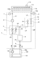
- FIG. 1 is a diagram showing a schematic configuration of a heat exchange system 1 according to a first embodiment of the present invention.
- a heat exchange system 1 is provided on a circulation path for circulating a refrigerant between a temperature control member 110 and a chiller apparatus 120.
- the refrigerant is an example of a "heat medium”.
- the chiller device 120 is a device that adjusts the refrigerant to a predetermined temperature and stores it.
- the temperature control member 110 is an example of a “control object” whose temperature is controlled by the flow of the refrigerant supplied from the chiller device 120.
- the chiller device 120 includes a tank 122 and a pump 124.
- the tank 122 stores a refrigerant adjusted to a predetermined temperature.
- the pump 124 sends the refrigerant stored in the tank 122 to the heat exchange system 1 at a predetermined flow rate.
- the chiller device 120 of the present embodiment has a chiller ability to control the temperature of the refrigerant to be lower than the set temperature of the temperature control member 110.
- the temperature control member 110 is, for example, internally installed in a reaction vessel (not shown) that performs an etching process to control the temperature of the wafer.
- the temperature control member 110 includes a heater 112 and a temperature sensor 114.
- the heater 112 heats the temperature control member 110.
- the temperature sensor 114 measures the temperature of the temperature control member 110.
- the temperature control member 110 is supplied with a refrigerant from the tank 122 of the chiller device 120 via the heat exchange system 1 according to the temperature measured by the temperature sensor 114, and is adjusted to a set temperature.
- the refrigerant flowing through the temperature control member 110 is returned to the tank 122 of the chiller device 120 via the heat exchange system 1.
- the heat exchange system 1 includes a forward circuit L1, a return circuit L2, and a bypass circuit L3. Further, the heat exchange system 1 includes a first temperature sensor 6, a second temperature sensor 7, a flow path switching unit 2, a flow rate distribution unit 3, a flow rate sensor 5, a heat storage unit 4, and a throttle valve 8. I have.
- the flow rate distribution unit 3 is an example of the “first flow rate distribution unit”.
- the heat storage unit 4 is an example of a “latent heat storage member”.
- the forward circuit L1 communicates the output port 120b of the chiller device 120 with the input unit 110a of the temperature control member 110, and supplies the refrigerant from the chiller device 120 to the temperature control member 110.
- the return circuit L2 is branched into the first branch circuit L21 and the second branch circuit L22 at the branch point P4.
- the branch point P4 is an example of the "first branch point”.
- the return circuit L2 communicates the output unit 110b of the temperature control member 110 with the input port 120a of the chiller device 120 via the first branch circuit L21, and returns the refrigerant supplied to the temperature control member 110 to the chiller device 120.
- the second branch circuit L22 is connected to the first branch circuit L21 at the third connection point P3.
- the bypass circuit L3 connects the outgoing circuit L1 and the first branch circuit L21 of the return circuit L2, and supplies the refrigerant from the outgoing circuit L1 to the first branch circuit L21 of the return circuit L2 without passing through the temperature control member 110. ..
- the first temperature sensor 6 is arranged in the return circuit L2.
- the first temperature sensor 6 measures the temperature (first temperature) of the refrigerant input from the temperature control member 110 to the return circuit L2.
- the return circuit L2 is branched into the first branch circuit L21 and the second branch circuit L22 at the branch point P4 located on the chiller device side (downstream side) of the first temperature sensor 6.
- the flow path switching portion 2 is arranged at the branch point P4.
- the flow path switching unit 2 includes a first on-off valve 21 and a second on-off valve 22.
- the first on-off valve 21 is arranged in the first branch circuit L21
- the second on-off valve 22 is arranged in the second branch circuit L22.
- the first branch circuit L21 communicates with the input port 120a of the chiller device 120.
- the heat storage unit 4 is arranged between the first connection point P1 connected to the bypass circuit L3 and the third connection point P3 connected to the second branch circuit L22.
- the throttle valve 8 is arranged on the chiller device 120 side (downstream side) from the third connection point P3.
- the heat storage unit 4 stores heat energy during a phase change between a solid and a liquid.
- the heat storage unit 4 heats the refrigerant by dissipating heat to the refrigerant by utilizing the heat storage energy according to the temperature of the refrigerant flowing through the first branch circuit L21.
- the heat storage unit 4 regenerates the heat storage energy by absorbing heat from the refrigerant.
- the specific configuration of the heat storage unit 4 will be described later.
- the throttle valve 8 adjusts the pressure loss in the system for circulating the refrigerant between the temperature control member 110 and the chiller device 120. That is, the throttle valve 8 adjusts the pressure of the refrigerant input to the input port 120a of the chiller device 120.
- the second branch circuit L22 is connected to a third connection point P3 provided on the downstream side of the heat storage unit 4 of the first branch circuit L21, and forms a flow path that bypasses the heat storage unit 4.
- the bypass circuit L3 is connected to a second connection point P2 provided in the forward circuit L1 and a first connection point P1 provided on the temperature control member 110 side (upstream side) from the heat storage unit 4 of the first branch circuit L21. doing.
- a flow rate distribution unit 3 is provided at the second connection point P2.
- the flow rate distribution unit 3 may be provided at a position on the forward circuit L1 that is closer to the temperature control member 110 than the second connection point P2.
- the flow rate distribution unit 3 includes a first opening proportional valve 31 and a second opening proportional valve 32.
- the first opening proportional valve 31 is arranged in the forward circuit L1
- the second opening proportional valve 32 is arranged in the bypass circuit L3.
- the flow rate distribution unit 3 operates in conjunction with the first opening proportional valve 31 and the second opening proportional valve 32, so that the flow rate distribution unit 3 has the first opening proportional valve 31 and the second opening proportional valve 32.
- the total opening degree of 32 being the same, that is, with the pressure loss of the refrigerant generated at the second connection point P2 being substantially constant, the ratio of distributing the refrigerant to the temperature control member 110 side and the bypass circuit L3 side is relatively high. Change.
- the flow rate distribution unit 3 may be composed of one spool valve.
- a flow rate sensor 5 and a second temperature sensor 7 are arranged on the temperature control member 110 side (downstream side) of the flow rate distribution unit 3.
- the flow rate sensor 5 measures the flow rate of the refrigerant flowing from the flow rate distribution unit 3 to the temperature control member 110.
- the flow rate sensor 5 measures the flow rate of the refrigerant circulating between the temperature control member 110 and the chiller device 120.
- the second temperature sensor 7 measures the temperature (second temperature) of the refrigerant flowing from the flow rate distribution unit 3 to the temperature control member 110.
- the arrangement of the flow rate sensor 5 and the second temperature sensor 7 may be reversed. Further, the flow rate sensor 5 may be omitted.
- FIG. 2 is an external perspective view of the heat storage unit 4.
- FIG. 3 is a cross-sectional view taken along the line AA of FIG.
- FIG. 4 is an enlarged view of part B of FIG.
- the shape and dimensional ratio of the heat storage unit 4 and its constituent members are not limited to those shown in FIGS. 2 and 3.
- FIG. 4 is schematically shown in order to make it easier to see the state in which the refrigerant has entered the voids 4123 of the metal fiber sheet 412, and the shapes and densities of the metal fibers 4121 and the voids 4123 are not limited thereto.
- the heat storage unit 4 of this embodiment applies, for example, the technique disclosed in Japanese Patent Application Laid-Open No. 2019-9433.
- the heat storage unit 4 has, for example, a box-shaped appearance, and includes a flow path forming member 41, a heat exchange member 42, and a heat insulating material 43.
- the flow path forming member 41 forms a flow path through which the refrigerant flows, and constitutes a part of the first branch circuit L21.
- the heat exchange member 42 exchanges heat with the refrigerant via the flow path forming member 41.
- the flow path forming member 41 and the heat exchange member 42 have a thin rectangular parallelepiped shape and have substantially the same external dimensions. Therefore, the flow path forming member 41 and the heat exchange member 42 can be stacked in a block shape.
- the flow path forming member 41 and the heat exchange member 42 may have different dimensions in the thickness direction as long as the dimensions of the surfaces that come into contact with each other are the same.
- the rectangular parallelepiped shape is not limited to a strict rectangular parallelepiped shape, and for example, the corners may be chamfered or the like.
- the flow path forming member 41 and the heat exchange member 42 are alternately stacked and arranged so that the heat exchange members 42 are arranged at both ends in the stacking direction.
- one flow path forming member 41 is arranged between the three heat exchange members 42, but the number of the heat exchange member 42 and the flow path forming member 41 is not limited to this.
- the heat insulating material 43 is provided so as to cover the outer periphery of the stacked flow path forming member 41 and the heat exchange member 42.
- the flow path forming member 41 and the heat exchange member 42 are shielded from external heat by the heat insulating material 43.
- the flow path forming member 41, the heat exchange member 42, and the heat insulating material 43 will be described in detail.
- the flow path forming member 41 includes a piping member 411 and a metal fiber sheet 412.
- the piping member 411 has a rectangular parallelepiped shape in which the upper surface located on the upper side in the drawing and the lower surface located on the lower side in the drawing have a large area, and the upper surface and the lower surface are connected by a pair of opposite side surfaces. Eggplant.
- a flow path through which the refrigerant flows is formed by a pair of side surfaces of the upper surface and the lower surface.
- the flow path surface 4111 is formed so that the cross-sectional shape of the flow path when cut in a direction orthogonal to the flow path axial direction is a horizontally long square shape in order to increase the flow path cross-sectional area.
- the piping member 411 is made of a material having high thermal conductivity, such as stainless steel, copper, and aluminum.
- the piping member 411 may be formed of the same material, but may be formed of a different material.
- the surfaces having a large area in contact with the heat exchange member 42 (upper surface and lower surface) may be formed of a material having high thermal conductivity, and the pair of opposing side surfaces may be formed of another material such as ceramic or resin.
- the metal fiber sheet 412 is formed by forming the metal fiber 4121 into a sheet shape.
- the metal fiber sheet 412 uses, for example, the technique disclosed in Japanese Patent Application Laid-Open No. 2019-9433.
- the metal fiber sheet 412 may be composed of the metal fiber 4121 alone, or may be configured in combination with a fiber other than the metal fiber 4121.
- the metal fiber 4121 is preferably formed of a material having high thermal conductivity, such as stainless steel, copper, and aluminum, in order to increase the heat exchange efficiency.
- the metal fiber 4121 of the present embodiment is a copper fiber having an excellent balance between rigidity and plastic deformability.
- the metal fibers 4121 are physically fixed to each other to form a binding portion C1, and the binding portion C1 forms a gap 4123 between the metal fibers 4121.
- the metal fiber 4121 is sintered at the binding portion C1 in order to stabilize the thermal conductivity and homogeneity of the metal fiber sheet 412.
- the piping member 411 is sintered in a manner that accommodates the metal fiber sheet 412, and includes a binding portion C2 that binds the metal fiber sheet 412 and the flow path surface 4111.
- the metal fibers 4121 may be directly bonded to each other, or may be indirectly bonded to each other via another substance.
- the binding portion C2 may be directly bound to the piping member 411 and the metal fiber 4121, or may be indirectly bound via another substance.
- the flow path forming member 41 when the refrigerant flows into the opening 413 located on the left side in the drawing in FIG. 3, the refrigerant is introduced into the gap 4123 of the metal fiber sheet 412, and the opening 414 located on the right side in the drawing. Is discharged from.
- innumerable voids 4123 are formed between the fine metal fibers 4121, so that the pressure loss when the refrigerant flows through the piping member 411 is small.
- the refrigerant and the piping member 411 transfer heat not only through the flow path surface 4111 but also through the metal fibers 4121 arranged in the flow path. Therefore, the flow path forming member 41 has good heat exchange efficiency between the refrigerant and the heat exchange member 42, and the piping member 411 tends to quickly reach the same temperature as the refrigerant.
- the heat exchange member 42 includes an accommodating body 421 and a latent heat storage material 422.
- the accommodating body 421 has a thin rectangular parallelepiped shape in which a pair of large areas are connected by four side surfaces, and includes an internal space 4211 filled with a latent heat storage material 422.
- the housing 421 may be formed of a material having good thermal conductivity such as metal. Further, for example, the housing body 421 may be a thinly molded ceramic resin or the like. Further, the housing 421 may be formed of metal and a material other than metal.
- an injection port 4212 for injecting the latent heat storage material 422 into the internal space 4211 is sealed by a plug 4213. The position and shape of the injection port 4212 are not limited to this.
- the heat storage temperature and heat storage energy of the heat exchange member 42 can be changed depending on the components and component ratios of the latent heat storage material 422.
- the heat exchange member 42 can have a heat storage temperature of 9.9 ° C. and a heat storage amount of 163.8 kJ / kg.
- the latent heat storage material 422 whose heat storage temperature is higher than the temperature of the refrigerant stored in the chiller device 120 and lower than the set temperature of the temperature control member 110 is used.
- FIG. 5 is an electric block diagram of the heat exchange system 1.
- the operation of the heat exchange system 1 is automatically controlled by the controller 11.
- the controller 11 is connected to the temperature sensor 114, the flow rate sensor 5, the first temperature sensor 6, and the second temperature sensor 7, and acquires information such as the flow rate and the temperature of the refrigerant. Further, the controller 11 is connected to the first on-off valve 21 and the second on-off valve 22 of the flow path switching unit 2 to supply a voltage to perform the valve opening operation, while stopping the voltage supply to perform the valve closing operation. To do.
- the controller 11 causes the first on-off valve 21 and the second on-off valve 22 to perform opening / closing operations relatively, and communicates the return circuit L2 with either the first branch circuit L21 or the second branch circuit L22.
- controller 11 connects to the first opening proportional valve 31 and the second opening proportional valve 32 of the flow rate distribution unit 3 and the throttle valve 8 and outputs a command signal for controlling the valve opening. Further, the controller 11 is connected to the communication interface (communication IF) 12.
- the host controller 130 is communicably connected to the controller 11 via the communication IF 12, and includes information on changes in the set temperature of the temperature control member 110, information on the temperature of the temperature control member 110, information on heat input by plasma, and the like. Is transmitted to the controller 11.
- the host controller 130 may have all the functions of the controller 11 and the controller 11 may be omitted. Further, the host controller 130 may have a part of the functions of the controller 11. Further, for example, when the first on-off valve 21 and the second on-off valve 22 are operated by air pressure or the like, the controller 11 does not always supply a voltage to the first on-off valve 21 and the second on-off valve 22.
- the command signal may be a command voltage, a command current, or a signal output by serial communication.
- the heat exchange system 1 performs a steady operation operation and a heat exchange operation.
- the "steady operation operation” means that the heat exchange system 1 controls the flow of the refrigerant so that the latent heat storage material 422 of the heat storage unit 4 absorbs the heat of the refrigerant and is regenerated (stores heat).
- the “heat exchange operation” refers to an operation in which the heat exchange system 1 controls the flow of the refrigerant so that the latent heat storage material 422 of the heat storage unit 4 dissipates heat to the refrigerant.
- the controller 11 closes the first on-off valve 21 of the flow path switching unit 2 and opens the second on-off valve 22. Then, for example, the controller 11 acquires the difference between the temperature of the temperature control member 110 and the set temperature from the host controller 130, and according to the difference, the first opening proportional valve 31 and the second opening of the flow rate distribution unit 3 are opened. The valve opening degree of the degree proportional valve 32 is changed in conjunction with it.
- the controller 11 outputs a command signal for setting the valve opening degree to 25% to the first opening degree proportional valve 31 so as to cool the temperature control member 110 by the amount heated by the heater 112, and the second opening degree.
- a command signal with a valve opening of 75% is output to the proportional valve 32.
- the refrigerant output from the output port 120b of the chiller device 120 is 25% distributed to the temperature control member 110 side and 75% to the bypass circuit L3 side.
- the heat exchange system 1 has, for example, the first opening proportional valve 31 and the second temperature according to the difference between the first temperature measured by the first temperature sensor 6 and the second temperature measured by the second temperature sensor 7.
- the valve opening degree of the opening degree proportional valve 32 may be adjusted.
- the refrigerant distributed from the flow rate distribution unit 3 to the temperature control member 110 side exchanges heat with the temperature control member 110 when flowing through the temperature control member 110 heated by the heater 112, so that the refrigerant is sent to the input unit 110a of the temperature control member 110.
- the temperature is higher when the temperature is output from the output unit 110b of the temperature control member 110 than when the temperature is input.
- the refrigerant output from the output unit 110b is input to the return circuit L2. Since the first on-off valve 21 is closed and the second on-off valve 22 is opened, the flow path switching unit 2 arranged in the return circuit L2 flows to the second branch circuit L22 side and the heat storage unit 4 It is returned to the chiller device 120 without passing through.
- the refrigerant distributed from the flow rate distribution unit 3 to the bypass circuit L3 side flows into the first branch circuit L21 via the first connection point P1 and is returned to the chiller device 120 through the heat storage unit 4. ..
- the refrigerant passes through the heat storage unit 4 through the void 4123 of the metal fiber sheet 412 provided internally in the piping member 411.
- the heat of the refrigerant is transmitted to the piping member 411 via the flow path surface 4111, is transmitted to the metal fiber 4121 of the metal fiber sheet 412, and is transferred to the piping member 411 via the binding portions C1 and C2. Therefore, the temperature of the piping member 411 and the metal fiber sheet 412 quickly reaches the same temperature as that of the refrigerant.
- the heat exchange member 42 and the piping member 411 are in contact with each other having a large area.
- the latent heat storage material 422 filled in the heat exchange member 42 has a large area for heat exchange with the piping member 411 via the accommodating body 421, and absorbs the heat of the refrigerant through the piping member 411 and the metal fiber sheet 412. , Will be played. Since the heat storage unit 4 is covered with the heat insulating material 43, heat dissipation loss is unlikely to occur.
- the heat storage unit 4 is arranged between the first connection point P1 and the third connection point P3. Therefore, during the steady operation operation, the refrigerant output from the chiller device 120 can flow through the heat storage unit 4 more than the refrigerant heated by the temperature control member 110. Therefore, in the heat storage unit 4, the latent heat storage material 422 of the heat exchange member 42 absorbs heat from the cold refrigerant stored in the tank 122 of the chiller device 120 and is efficiently regenerated. Further, since the heat storage unit 4 is regenerated by using the refrigerant stored in the chiller device 120, it is regenerated with energy saving.
- the refrigerant flowing through the second branch circuit L22 merges with the refrigerant flowing through the heat storage unit 4 at the third connection point P3, the temperature is lowered, and then the refrigerant is returned to the chiller device 120. Therefore, even if the refrigerant flowing from the temperature control member 110 into the return circuit L2 is returned to the chiller device 120 without passing through the heat storage unit 4, the load of cooling the refrigerant input by the chiller device 120 to the input port 120a is small. I'm done.
- the controller 11 opens the first on-off valve 21 of the flow path switching unit 2 and closes the second on-off valve 22 of the flow path switching unit 2. Then, the controller 11 acquires the difference between the temperature of the temperature control member 110 and the set temperature from the host controller 130, and the first opening proportional valve 31 and the second opening proportional to the flow rate distribution unit 3 according to the difference.
- the valve opening degree of the valve 32 is changed in conjunction with it. In this case, since it is necessary to quickly lower the temperature of the temperature control member 110, the controller 11 transmits, for example, a command signal for setting the valve opening to 95% to the first opening proportional valve 31, and the second opening. A command signal with a valve opening of 5% is transmitted to the proportional valve 32. In this case, the refrigerant output from the output port 120b of the chiller device 120 is distributed 95% to the temperature control member 110 side and 5% to the bypass circuit L3 side.
- the refrigerant distributed from the flow rate distribution unit 3 to the temperature control member 110 side flows into the return circuit L2 in the same manner as during the steady operation operation.
- the refrigerant flowing into the return circuit L2 has a larger flow rate and a larger amount of heat than during steady operation. Since the first on-off valve 21 of the flow path switching unit 2 is opened and the second on-off valve 22 of the flow path switching unit 2 is closed, the refrigerant flowing into the return circuit L2 is on the first branch circuit L21 side. And returned to the chiller device 120 via the heat storage unit 4.
- the flow rate distribution unit 3 distributes the refrigerant to the return circuit L2 side, it is distributed to the first branch circuit L21 to the first connection point P1 on the upstream side of the heat storage unit 4 and from the flow rate distribution unit 3 to the bypass circuit L3 side. Refrigerant flows in. Therefore, the refrigerant flowing from the bypass circuit L3 into the first branch circuit L21 merges with the cold refrigerant flowing from the bypass circuit L3 into the first connection point P1 before flowing into the heat storage unit 4, and the temperature can be lowered.
- the refrigerant flows through the flow path forming member 41 of the heat storage unit 4 and flows into the input port 120a of the chiller device 120.
- the refrigerant flows through the void 4123 of the metal fiber sheet 412 installed in the piping member 411, and when passing through the heat storage unit 4, heat exchanges with the heat exchange member 42 via the metal fiber 4121 and the piping member 411.
- the heat of the refrigerant is transferred from the metal fibers 4121 to the piping member 411 via the binding portions C1 and C2, and the temperature quickly reaches the same level as that of the refrigerant.
- the heat exchange member 42 transfers the heat of the latent heat storage material 422 to the piping member 411 via the housing 421, and cools the refrigerant through the piping member 411 and the metal fiber sheet 412. In this way, the refrigerant can efficiently exchange heat with the latent heat storage material 422 via the piping member 411 and the metal fiber 4121, so that the refrigerant is quickly cooled to a temperature similar to that of the latent heat storage material 422.
- the heat storage temperature rises in response to applying heat to the refrigerant during the heat exchange operation.
- the chiller device 120 the refrigerant whose temperature is lower than the temperature when it flows into the return circuit L2 from the temperature control member 110 flows into the input port 120a. Therefore, even when the chiller device 120 circulates the refrigerant with the temperature control member 110, the load of cooling the refrigerant input to the input port 120a is reduced.
- the controller 11 of the heat exchange system 1 has, for example, a steady operation operation and a heat exchange operation according to the amount of heat of the refrigerant returned to the chiller device 120, that is, a value obtained by multiplying the temperature and the flow rate of the refrigerant returned to the chiller device 120. Automatically switches.
- FIG. 8 shows a specific example of the condition for switching the operation (hereinafter referred to as “switching condition”).
- the heat exchange system 1 of this embodiment is used in a unit that regulates the temperature of the temperature control member 110 by supplying a refrigerant having a temperature lower than the set temperature of the temperature control member 110 to the temperature control member 110. Therefore, the controller 11 automatically switches the operation of the heat exchange system 1 by using, for example, the switching condition shown in FIG. 8A.
- the controller 11 provides the set temperature drop information for lowering the set temperature of the temperature control member 110 from the current value from the host controller 130. May be received. Further, for example, the controller 11 may detect that the temperature control member 110 has generated a steep temperature rise based on the temperature measurement value received from the temperature sensor 114. Further, for example, there is a case where the controller 11 receives heat input on information indicating that the temperature control member 110 is heated by plasma or the like from the host controller 130. Further, for example, the controller 11 may set the flow rate distribution rate for distributing the refrigerant output from the chiller device 120 to the temperature control member 110 side in the flow rate distribution unit 3 to a predetermined value or more.
- the temperature of the temperature control member 110 is stable at the set temperature based on the temperature measurement value received by the controller 11 from the temperature sensor 114. It may have been detected. Further, for example, the controller 11 may have a built-in timer for measuring the time, and the set time may have elapsed since the heat exchange operation was started. Further, for example, the controller 11 may set the flow rate distribution rate for distributing the refrigerant output from the chiller device 120 to the temperature control member 110 side in the flow rate distribution unit 3 to be less than a predetermined value.
- the set temperature decrease information may be received before the set temperature is lowered, or may be received after the set temperature is lowered.
- the heat input on information may be received before heat input or after heat input.
- the controller 11 may switch the steady operation operation to the heat exchange operation by the upper controller 130 detecting a steep temperature rise and receiving the detection result from the upper controller 130.
- the embodiment is configured in the same manner as the heat exchange system 1 of the present embodiment.
- the comparative example has the same configuration as the heat exchange system 1 of the present embodiment except that the second branch circuit L22, the flow path switching unit 2, and the heat storage unit 4 are not provided.
- the chiller device 120 stores the refrigerant at ⁇ 20 ° C. in the tank 122, and uses the pump 124 to send the refrigerant from the tank 122 to the outgoing circuit L1 at a flow rate of 35 L / min.
- the heat storage unit 4 of the embodiment uses a heat exchange member 42 filled with a latent heat storage material 422 having a heat storage temperature of ⁇ 10 ° C.
- the set temperature of the temperature control member 110 is set to 60 ° C. or 0 ° C., and the temperature of the temperature control member 110 is adjusted to the set temperature by the heater 112 and the refrigerant distributed by the flow rate distribution unit 3 to the temperature control member 110 side. did.
- FIG. 9 shows an example of the operation of the comparative example and the change in the refrigerant temperature. An example of the operation of the embodiment and the change in the refrigerant temperature are shown in FIG.
- the flow rate distribution ratio to the temperature control member 110 side is stable, that is, the temperature of the temperature control member 110 is stable, and the first opening proportional valve 31
- the output value of the command signal output to is stable (Y21, Y44, Y64, Y75, Y85, Y104), as shown in Z2, Z4, Z6, Z10 in the figure, from the output port 120b of the chiller device 120.
- the temperature of the output refrigerant is stable at -20 ° C.
- the flow rate distribution ratio to the temperature control member 110 side sharply decreases, that is, in order to raise the temperature of the temperature control member 110, the output value of the command signal to the first opening proportional valve 31 is set. Even when the temperature is rapidly reduced (Y74, Y84, Y114), the temperature of the refrigerant output from the output port 120b of the chiller device 120 is stable at ⁇ 20 ° C., as shown in Z6 and Z10 in the figure.
- the refrigerant distributed to the bypass circuit L3 side has a larger flow rate than the refrigerant distributed to the temperature control member 110 side, so that the amount of heat of the refrigerant input to the input port 120a of the chiller device 120 is small, and the chiller This is considered to be because the load applied to the device 120 is small.
- the temperature control member 110 changes the set temperature from 60 ° C. to 0 ° C., that is, when the host controller receives information for changing the set temperature of the temperature control member 110 from 60 ° C. to 0 ° C. (X3), or when the temperature control member 110 causes a steep temperature rise due to the plasma being turned on, that is, when heat input information is received from the host controller (X5, X9), the temperature control member 110 moves to the temperature control member 110 side.
- the flow rate distribution ratio of is rapidly increased (Y34, Y54, Y94). That is, the output value of the command signal to the first opening proportional valve 31 suddenly increases. In this case, the temperature of the refrigerant output from the output port 120b of the chiller device 120 rises sharply as shown in Z3, Z5, and Z9 in the figure.
- the chiller device 120 can cope with the increase in the amount of heat of the refrigerant. Probably because it does not have the ability.
- the next process is performed after waiting for the temperature of the refrigerant output from the output port 120b of the chiller apparatus 120 to stabilize at ⁇ 20 ° C. Therefore, when the peak value is large as in the comparative example, the takt time of the semiconductor manufacturing apparatus becomes long. If the chiller capacity of the chiller device 120 is increased, the tact time can be shortened, but the chiller device 120 becomes larger. Since the semiconductor manufacturing apparatus is required to be compact, it is not preferable to increase the size of the chiller apparatus 120. Even when the plasma energy becomes large, the chiller capacity of the chiller device 120 is insufficient, and the same problem as described above may occur.
- the flow rate distribution ratio to the temperature control member 110 side is stable (Y21, Y44, Y64, Y75, Y85, Y104) or the temperature control.
- the first on-off valve 21 is closed and the second on-off valve 22 is opened to perform a steady operation operation (Y74, Y84, Y114).
- the latent heat storage material 422 is regenerated by the refrigerant output from the output port 120b of the chiller device 120 during the steady operation operation (Y28, Y48, Y68, Y108).
- the temperature of the refrigerant output from the output port 120b is stable at ⁇ 20 ° C. during steady operation (Z2, Z4, Z6, S10).
- the temperature is higher than when it is output from the output port 120b of the chiller device 120.
- the heat storage temperature of the latent heat storage material 422 is ⁇ 10 ° C.
- the temperature difference between the refrigerant flowing through the heat storage unit 4 and the refrigerant output from the output port 120b is smaller than that of the refrigerant flowing through the temperature control member 110. Therefore, the chiller device 120 can sufficiently regenerate the heat storage unit 4 with the chiller capacity required to cool the refrigerant flowing through the temperature control member 110.
- the first step is made. 1
- the on-off valve 21 is switched from the valve closed state to the valve open state, and the second on-off valve 22 is switched from the valve open state to the valve closed state, so that the steady operation operation is automatically switched to the heat exchange operation (Y32, Y33, Y52, Y53, Y92, Y93).
- the flow rate distribution unit 3 operates so as to increase the flow rate of the refrigerant supplied to the temperature control member 110 side in order to lower the temperature of the temperature control member 110 (Y34, Y54, Y94).
- the temperature of the refrigerant output from the output port 120b of the chiller device 120 rises, but the peak value thereof is smaller than that of the comparative example.
- the flow rate of the refrigerant input from the temperature control member 110 to the return circuit L2 increases from the steady operation operation, and the amount of heat increases, as in the comparative example.
- the refrigerant is returned to the chiller device 120 after the temperature is lowered by exchanging heat with the latent heat storage material 422 of the heat storage unit 4. Therefore, in the chiller device 120, the amount of heat of the refrigerant input to the input port 120a is smaller than in the comparative example. Therefore, in the embodiment, the refrigerant input to the input port 120a by the chiller device 120 can be easily cooled to near ⁇ 20 ° C., and the peak value of the temperature of the refrigerant output from the output port 120b can be suppressed as compared with the comparative example.
- the time required to stabilize the temperature of the refrigerant when the peak value is generated (t3x, t5x, t9x in the figure) is shorter than the time in the comparative example (t3, t5, t9).
- the semiconductor manufacturing apparatus used can have a shorter takt time than the semiconductor manufacturing apparatus using the comparative example. Further, since it is not necessary to increase the size of the chiller device 120 to change the chiller capacity, the size of the semiconductor manufacturing device can be maintained. Further, even when the plasma energy becomes large, if the latent heat storage material 422 of the heat storage unit 4 is changed, it is not necessary to replace the chiller device 120.
- the heat storage unit 4 Since the heat exchange system 1 is automatically switched to the steady operation operation after the heat exchange operation, the heat storage unit 4 utilizes the heat of the refrigerant by the steady operation operation for the heat storage energy lost during the heat exchange operation. Will be recovered automatically. Therefore, the heat exchange system 1 can continuously reduce the load on the chiller device 120 with energy saving.
- the heat exchange system 1 of the present embodiment utilizes the thermal energy of the heat storage unit 4 and returns the refrigerant supplied from the chiller device 120 to the temperature control member 110 from the temperature control member 110 to the chiller device 120.
- the temperature difference between the refrigerant returned from the temperature control member 110 to the chiller device 120 and the refrigerant stored in the chiller device 120 is reduced by merging with the refrigerant, so that the load on the chiller device 120 is reduced. can do.
- the chiller device 120 since the load is reduced, the chiller device 120 may have a chiller capacity lower than the temperature of the refrigerant output from the temperature control member 110, and a miniaturized one can be used.
- the flow distribution unit 3 allows the refrigerant supplied from the chiller device 120 to flow to the bypass circuit L3 side, so that the heat storage unit 4 can be regenerated by the heat of the refrigerant, thus saving energy.
- the load on the chiller device 120 can be reduced.
- the heat storage unit 4 when the return circuit L2 is branched into the first branch circuit L21 and the second branch circuit L22 and the heat storage unit 4 is regenerated, the fluid returned from the temperature control member 110 is stored in the heat storage unit. Since it is possible to return the heat storage unit 4 to the chiller device 120 without passing through the heat storage unit 4, the heat storage unit 4 can be efficiently regenerated.
- the heat exchange system 1 exchanges heat with the heat exchange member 42 when the refrigerant flows through the piping member 411, the heat exchange efficiency between the refrigerant and the heat exchange member 42 can be improved.
- the refrigerant flows through the piping member 411 through the gap 4123 of the metal fiber sheet 412 and exchanges heat with the heat exchange member 42 via the metal fiber sheet 412 and the piping member 411. Therefore, when the refrigerant flows through the heat storage unit 4.
- the heat exchange efficiency between the refrigerant and the heat exchange member 42 can be improved while suppressing the pressure loss that occurs.
- the heat exchange efficiency between the piping member 411 and the heat exchange member 42 can be improved while ensuring the flow rate of the heat medium. ..
- the chiller device 120 stores a high temperature medium having a temperature higher than the set temperature of the temperature control member 110 instead of the refrigerant, and circulates the high temperature medium to the temperature control member 110 to heat the temperature control member 110. You can do it.
- the heat exchange system 1 does not change the circuit configuration, and the heat exchange member 42 of the heat storage unit 4 is compatible with high temperature, for example, when the temperature of the high temperature medium is 90 ° C, the heat storage temperature is 80 ° C. You can replace it with.
- the heat exchange system 1 can efficiently regenerate the heat storage unit 4 by dissipating heat from the high temperature medium by performing a steady operation operation in the same manner as the above-mentioned refrigerant.
- the heat storage unit 4 absorbs heat from the high-temperature medium to raise the heat storage temperature.
- the high temperature medium loses heat to the heat storage unit 4 and lowers the temperature.
- the heat exchange system 1 performs the heat exchange operation in the same manner as described above to heat the high temperature medium whose temperature has been lowered by heat dissipation of the temperature control member 110 and the piping portion by the heat storage unit 4 and then to the chiller device 120. Since it can be returned, the load on the chiller device 120 can be reduced. That is, the heat storage unit 4 applies heat to the high-temperature medium to lower the heat storage temperature. On the other hand, the high temperature medium is given heat from the heat storage unit 4 to raise the temperature.
- the controller 11 is used as a unit that supplies a high temperature medium having a temperature higher than the set temperature of the temperature control member 110 to the temperature control member 110 to adjust the temperature of the temperature control member 110. Therefore, the controller 11 automatically switches the operation of the heat exchange system 1 by using, for example, the switching condition shown in FIG. 8B.
- the controller 11 provides the set temperature rise information for raising the set temperature of the temperature control member 110 from the current value from the host controller 130. May be received. Further, for example, the controller 11 may detect that the temperature control member 110 has caused a steep temperature drop based on the temperature measurement value received from the temperature sensor 114. Further, for example, the controller 11 may receive the heat input off information from the host controller 130. Further, for example, the controller 11 may set the flow rate distribution rate for distributing the refrigerant output from the chiller device 120 to the temperature control member 110 side in the flow rate distribution unit 3 to be less than a predetermined value.
- the temperature of the temperature control member 110 is stable at the set temperature based on the temperature measurement value received by the controller 11 from the temperature sensor 114. It may have been detected. Further, for example, the controller 11 may have a built-in timer for measuring the time, and the set time may have elapsed since the heat exchange operation was started. Further, for example, the controller 11 may set the flow rate distribution rate for distributing the refrigerant output from the chiller device 120 to the temperature control member 110 side in the flow rate distribution unit 3 to a predetermined value or more.
- set temperature rise information may be received before raising the set temperature, or may be received after raising the set temperature.
- the heat input off information may be received before the heat input is stopped, or may be received after the heat input is stopped.
- FIG. 11 is a schematic configuration diagram of the heat exchange system 1001 according to the second embodiment of the present invention.
- the heat exchange system 1001 of the second embodiment is different from the first embodiment in that the first branch circuit L21 is further branched and the flow path can be switched by the flow path switching unit 1200.
- the points different from those of the first embodiment will be described, and the same reference numerals as those of the first embodiment will be added to the drawings for the configurations common to the first embodiment, and the description thereof will be omitted as appropriate.
- the first branch circuit L21 of the heat exchange system 1001 branches into the third branch circuit L211 and the fourth branch circuit L212 at the branch point P5 provided on the chiller device 120 side (downstream side) from the first connection point P1. There is.
- the third branch circuit L211 communicates with the chiller device 120 and is provided with a throttle valve 8.
- the fourth branch circuit L212 is connected to the second branch circuit L22, and the heat storage unit 4 is arranged.
- a flow path switching unit 1200 is provided at the branch point P5.
- the flow path switching unit 1200 includes a first on-off valve 1202 and a second on-off valve 1204.
- the first on-off valve 1202 is arranged in the third branch circuit L211 and the second on-off valve 1204 is arranged in the fourth branch circuit L212.
- the flow path switching unit 1200 switches the flow path of the refrigerant that has flowed from the chiller device 120 into the first branch circuit L21 via the flow rate distribution unit 3.
- the flow path switching unit 1200 is an example of the “second flow rate distribution unit”.
- the heat exchange system 1001 performs the regeneration operation shown in FIG. 12, the unused operation shown in FIG. 13, and the heat exchange operation shown in FIG.
- the “regeneration operation” refers to an operation of regenerating the latent heat storage material 422 of the heat storage unit 4 using the refrigerant output from the chiller device 120.
- the “unused operation” means an operation in which the heat storage unit 4 is not used.
- the controller 11 of the heat exchange system 1001 opens the second on-off valve 22 of the flow path switching unit 2 and the second on-off valve 1204 of the flow path switching unit 1200 when performing the regeneration operation.
- the first on-off valve 21 of the flow path switching unit 2 and the first on-off valve 1202 of the flow path switching unit 1200 are closed.
- the controller 11 operates the flow rate distribution unit 3 so as to stabilize the temperature of the temperature control member 110 to the set temperature.
- the refrigerant distributed from the flow rate distribution unit 3 to the temperature control member 110 side is the temperature control member 110. After exchanging heat with, it flows to the return circuit L2 and the second branch circuit L22, and is returned to the chiller device 120 without passing through the heat storage unit 4.
- the refrigerant distributed from the flow rate distribution unit 3 to the bypass circuit L3 side has the first on-off valve 1202 of the flow path switching unit 1200 closed and the second on-off valve 1204 opened, so that the fourth branch circuit L212 Flow to. Therefore, the refrigerant is returned to the chiller device 120 through the heat storage unit 4. At this time, the heat exchange member 42 of the heat storage unit 4 exchanges heat with the refrigerant flowing through the flow path forming member 41 and is regenerated.
- the controller 11 of the heat exchange system 1001 opens the second on-off valve 22 of the flow path switching unit 2 and the first on-off valve 1202 of the flow path switching unit 1200 when performing an unused operation.
- the first on-off valve 21 of the flow path switching unit 2 and the second on-off valve 1204 of the flow path switching unit 1200 are closed.
- the heat exchange system 1001 adjusts the flow rate of the refrigerant distributed by the flow rate distribution unit 3 to the temperature control member 110 side and the bypass circuit L3 side so as to stabilize the temperature of the temperature control member 110.
- the refrigerant supplied from the flow rate distribution unit 3 to the temperature control member 110 side is returned to the chiller device 120 in the same manner as in the regeneration operation.
- the second on-off valve 1204 of the flow path switching unit 1200 is closed and the first on-off valve 1202 is opened, so that the third branch circuit L211 Flow to. Therefore, the refrigerant does not exchange heat with the heat exchange member 42 of the heat storage unit 4, but is returned to the chiller device 120 while maintaining the temperature output from the chiller device 120.
- the heat exchange system 1001 when performing the heat exchange operation, valves the first on-off valve 21 of the flow path switching unit 2 and the second on-off valve 1204 of the flow path switching unit 1200. It is opened, and the second on-off valve 22 of the flow path switching unit 2 and the first on-off valve 1202 of the flow path switching unit 1200 are closed.
- the flow rate distribution unit 3 operates so as to increase the flow rate of the refrigerant supplied to the temperature control member 110 side.
- the refrigerant supplied from the flow rate distribution unit 3 to the temperature control member 110 side is the temperature control member 110. After cooling, it flows to the return circuit L2 and the first branch circuit L21. Then, since the first on-off valve 1202 of the flow path switching unit 1200 is closed and the second on-off valve 1204 is opened, the refrigerant flows into the fourth branch circuit L212 and passes through the heat storage unit 4 to the chiller. Returned to device 120.
- the refrigerant flowing through the heat storage unit 4 exchanges heat with the heat exchange member 42 when flowing through the flow path forming member 41. Therefore, the refrigerant cooled to the same temperature as the heat exchange member 42 is returned to the chiller device 120, so that the load of cooling the refrigerant in the chiller device 120 is reduced.
- the controller 11 switches the operation of the heat exchange system 1001 according to the following switching conditions. That is, the controller 11 automatically switches the heat exchange operation to the regeneration operation or the unused operation according to any switching condition for switching the heat exchange operation to the steady operation operation in FIG. 8A. Further, the controller 11 automatically switches the regeneration operation or the unused operation to the heat exchange operation according to any switching condition for switching the steady operation operation of FIG. 8A to the heat exchange operation.
- the controller 11 executes a regeneration operation when the heat amount of the heat storage unit 4 is less than a predetermined heat amount, and executes an unused operation when the heat amount of the heat storage unit 4 is equal to or more than the predetermined heat amount. Further, for example, the controller 11 switches between an unused operation and a reproduction operation according to the time.
- the heat exchange system 1001 of the present embodiment can switch the flow path by using the flow path switching unit 1200 as needed to regenerate the heat storage unit 4, so that the heat storage unit 4 is useless. Regeneration can be avoided and the energy saving effect can be enhanced.
- the flow path switching unit 1200 bypasses the first branch circuit L21 to either the third branch circuit L211 or the fourth branch circuit L212 by using the first on-off valve 1202 and the second on-off valve 1204. All the refrigerant that flowed from the circuit L3 to the first branch circuit L21 was supplied.
- the flow path switching unit 1200 may be a flow rate distribution unit configured in the same manner as the flow rate distribution unit 3. That is, by arranging the first opening proportional valve in the third branch circuit L211 and arranging the second opening proportional valve in the fourth branch circuit L212, the refrigerant flowing into the first branch circuit L21 from the bypass circuit L3 is transferred. , The third branch circuit L211 and the fourth branch circuit L212 may be distributed. In this case, the heat exchange system 1001 can perform the regeneration operation by flowing the refrigerant through the heat storage unit 4 at a flow rate corresponding to the heat storage amount of the heat storage unit 4, and can suppress unnecessary regeneration operation.
- FIG. 15 is a schematic configuration diagram of the heat exchange system 2001 according to the third embodiment of the present invention.
- the heat exchange system 2001 is provided on a circulation path for circulating a temperature control fluid between the temperature control member 110, the low temperature chiller device 2120A, and the high temperature chiller device 2120B.
- the temperature control fluid is an example of a "heat medium”.
- the heat exchange system 2001 is different from the first embodiment in that it includes two types of low-temperature heat storage units 4A and high-temperature heat storage units 4B having different heat storage temperatures.
- the low temperature chiller device 2120A is an example of the "first chiller device”.
- the high temperature chiller device 2120B is an example of a "second chiller device”.
- the temperature of the temperature control member 110 is adjusted by the heater 112 and the temperature control fluid.
- the heater 112 may not be provided.
- the low temperature chiller device 2120A stores a low temperature fluid lower than the temperature control fluid circulating in the temperature control member 110 in the low temperature tank 2122A, and sends the low temperature fluid to the temperature control member 110 side by using the low temperature pump 2124A. ..
- the high temperature chiller device 2120B stores a high temperature fluid having a higher temperature than the low temperature fluid and the temperature control fluid circulating in the temperature control member 110 in the high temperature tank 2122B, and uses the high temperature pump 2124B to store the low temperature fluid in the temperature control member 110. I am sending it to the side.
- the low temperature chiller device 2120A adjusts the temperature of the low temperature fluid to ⁇ 20 ° C.
- the high temperature chiller device 2120B adjusts the temperature of the high temperature fluid to 90 ° C.
- the low temperature fluid and the high temperature fluid are examples of "heat medium”.
- the low temperature fluid is an example of a "first heat medium”.
- the high temperature fluid is an example of a "second heat medium”.
- the heat exchange system 2001 includes an output circuit L51, an input circuit L52, a connection circuit L53, a low temperature fluid forward circuit L61, a low temperature fluid return circuit L62, a low temperature fluid bypass circuit L63, and a high temperature fluid forward circuit. It is provided with L71, a return circuit L72 for high temperature fluid, and a bypass circuit L73 for high temperature fluid.
- the low temperature fluid forward circuit L61 is an example of a forward circuit and a first forward circuit
- the low temperature fluid return circuit L62 is an example of a return circuit and a first return circuit
- the low temperature fluid bypass circuit L63 is a bypass circuit.
- the high temperature fluid forward circuit L71 is an example of a forward circuit and a second forward circuit
- the high temperature fluid return circuit L72 is an example of a return circuit and a second return circuit
- the high temperature fluid bypass circuit L73 is a bypass circuit.
- the output circuit L51, the input circuit L52, and the connection circuit L53 are examples of the main circulation circuit.
- the output circuit L51 supplies the temperature control fluid to the temperature control member 110.
- the input circuit L52 inputs the temperature control fluid from the temperature control member 110.
- the connection circuit L53 connects the output circuit L51 and the input circuit L52.
- a circulation pump 2002 is provided in the input circuit L52.
- the temperature control fluid can be circulated at a constant flow rate between the temperature control member 110 and the heat exchange system 2001 via the output circuit L51, the input circuit L52, and the connection circuit L53 by the pump operation of the circulation pump 2002. it can.
- the circulation pump 2002 may be provided outside the heat exchange system 2001.
- the low temperature fluid forward circuit L61 connects the low temperature chiller device 2120A and the output circuit L51, and supplies the low temperature fluid from the low temperature chiller device 2120A to the temperature control member 110.
- the return circuit L62 for low temperature fluid connects the input circuit L52 and the low temperature chiller device 2120A, and returns the temperature control fluid to the low temperature chiller device 2120A.
- the return circuit L62 for low temperature fluid is branched into a first branch circuit L621 for low temperature fluid and a second branch circuit L622 for low temperature fluid at the branch point P4A as in the first embodiment. Similar to the first embodiment, the branch point P4A is provided with a low temperature flow path switching portion 2A.
- the low-temperature fluid forward circuit L61 and the low-temperature fluid first branch circuit L621 are connected via the low-temperature fluid bypass circuit L63 as in the first embodiment.
- the low temperature heat storage unit 4A is arranged on the low temperature chiller device 2120A side from the connection point P1A connected to the low temperature fluid bypass circuit L63.
- a heat exchange member 42 having a heat storage temperature of ⁇ 10 ° C. is used in the low temperature heat storage unit 4A of this embodiment.
- the high temperature fluid forward circuit L71 connects the high temperature chiller device 2120B and the output circuit L51, and supplies the high temperature fluid from the high temperature chiller device 2120B to the temperature control member 110.
- the return circuit L72 for high temperature fluid connects the input circuit L52 and the high temperature chiller device 2120B, and returns the temperature control fluid to the high temperature chiller device 2120B. Similar to the first embodiment, the high temperature fluid return circuit L72 is branched into the high temperature fluid first branch circuit L721 and the high temperature fluid second branch circuit L722 at the branch point P4B. Similar to the first embodiment, the branch point P4B is provided with a high temperature flow path switching portion 2B.
- the high-temperature fluid forward circuit L71 and the high-temperature fluid first branch circuit L721 are connected via the high-temperature fluid bypass circuit L73 as in the first embodiment.
- the high temperature heat storage unit 4B is arranged on the high temperature chiller device 2120B side from the connection point P1B connected to the high temperature fluid bypass circuit L73.
- a heat exchange member 42 having a heat storage temperature of 80 ° C. is used in the high temperature heat storage unit 4B of this embodiment.
- the branch points P4A and P4B are examples of the first branch point, respectively, and the low temperature flow path switching unit 2A and the high temperature flow path switching unit 2B are examples of the flow path switching units, respectively.
- the first branch circuit L621 for low temperature fluid and the first branch circuit L721 for high temperature fluid are examples of the first branch circuit, respectively, and the second branch circuit L622 for low temperature fluid and the second branch circuit L722 for high temperature fluid are the first, respectively.
- This is an example of a two-branch circuit.
- the low temperature heat storage unit 4A is an example of a latent heat storage member and a first latent heat storage member
- the high temperature heat storage unit 4B is an example of a latent heat storage member and a second latent heat storage member.
- the connection point P1A is an example of the first connection point and the low temperature side connection point
- the connection point P1B is an example of the first connection point and the high temperature side connection point.
- the heat exchange system 2001 is provided with a flow rate distribution unit 2003 at a confluence point P6 where the connection circuit L53, the low temperature fluid forward circuit L61, and the high temperature fluid forward circuit L71 meet.
- the merging point P6 and the flow rate distribution unit 2003 are from the connection point P2A between the low temperature fluid forward circuit L61 and the low temperature fluid bypass circuit L63, and the connection point P2B between the high temperature fluid forward circuit L71 and the high temperature fluid bypass circuit L73. , Is provided on the temperature control member 110 side.
- the flow rate distribution unit 2003 is, for example, a spool valve, which is a communication between the first opening proportional unit V1 for adjusting the communication state between the connection circuit L53 and the output circuit L51, and the low temperature fluid forward circuit L61 and the output circuit L51.
- a second opening proportional portion V2 for adjusting the state and a third opening proportional portion V3 for adjusting the communication state between the high temperature fluid forward circuit L71 and the output circuit L51 are provided.
- the flow rate distribution unit 2003 is used for temperature control by operating the first opening proportional section V1 to the third opening proportional section V3 in conjunction with each other in a state where the flow rate of the temperature control fluid output to the output circuit L51 is stabilized.
- the mixing ratio of the fluid, the low temperature fluid, and the high temperature fluid is adjusted, and the temperature of the temperature control fluid output from the output circuit L51 to the temperature control member 110 is controlled. That is, the low temperature fluid is distributed to the temperature control member 110 side and the low temperature fluid bypass circuit L63 side according to the distribution ratio of the flow rate distribution unit 2003, and the high temperature fluid is distributed to the temperature control member 110 side and the high temperature fluid bypass circuit L73. Distributed to the side.
- the flow rate distribution unit 2003 is an example of the first flow rate distribution unit and the flow rate distribution unit
- the confluence point P6 is an example of the confluence unit.
- the connection points P2A and P2B are examples of the second connection points, respectively.
- Check valves CV1, CV2, and CV3 are arranged at the branch point P7 where the connection circuit L53, the return circuit L62 for low temperature fluid, and the return circuit L72 for high temperature fluid branch.
- the branch point P7 is an example of a flow dividing unit
- the check valves CV1, CV2, and CV3 are examples of a flow dividing control unit.
- the check valve CV1 is arranged in the connection circuit L53
- the check valve CV2 is arranged in the low temperature fluid return circuit L62
- the check valve CV3 is arranged in the high temperature fluid return circuit L72
- the temperature control fluid flows to the connection circuit L53, the low temperature fluid return circuit L62, and the high temperature fluid return circuit L72 according to the distribution ratio.
- the controller 11 of such a heat exchange system 2001 switches between the heat exchange operation and the steady operation operation on the low temperature chiller device 2120A side according to any of the switching conditions shown in FIG. 8A, and heat exchange on the high temperature chiller device 2120B side.
- the operation and the steady operation operation are switched according to any of the switching conditions shown in FIG. 8B.
- the controller 11 closes the first on-off valves 21A and 21B of the low temperature flow path switching unit 2A and the high temperature flow path switching unit 2B. , The second on-off valves 22A and 22B are opened.
- the controller 11 operates the flow rate distribution unit 2003 so that the low temperature fluid is merged with the temperature control fluid so as to cool the temperature control member 110 by the amount of heating of the heater 112, and the high temperature fluid is not merged.
- both the low temperature chiller device 2120A side and the high temperature chiller device 2120B side perform the steady operation operation as in the first embodiment, and the low temperature heat storage unit 4A and the high temperature heat storage unit 4B are regenerated.
- the controller 11 when the controller 11 receives the set temperature drop information when the temperature of the temperature control member 110 is stable, the controller 11 opens the first on-off valve 21A of the low temperature flow path switching unit 2A to open the first on-off valve 21A. 2 The on-off valve 22A is closed. The controller 11 operates the flow rate distribution unit 2003 so that the low temperature fluid is merged with the temperature control fluid and the high flow fluid is not merged. As a result, on the low temperature chiller device 2120A side, the heat exchange operation is performed as in the first embodiment, and the load on the low temperature chiller device 2120A is reduced. On the other hand, on the high temperature chiller device 2120B side, the steady operation operation is performed as in the first embodiment, and the high temperature heat storage unit 4B is regenerated.
- the controller 11 when the controller 11 receives the set temperature rise information when the temperature of the temperature control member 110 is stable, the controller 11 opens the first on-off valve 21B of the high temperature flow path switching unit 2B to open the valve. 2 The on-off valve 22B is closed. The controller 11 operates the flow rate distribution unit 2003 so that the high temperature fluid is merged with the temperature control fluid and the low temperature fluid is not merged. As a result, on the high temperature chiller device 2120B side, the heat exchange operation is performed as in the first embodiment, and the load on the high temperature chiller device 2120B is reduced. On the other hand, on the low temperature chiller device 2120A side, the steady operation operation is performed as in the first embodiment, and the low temperature heat storage unit 4A is regenerated.
- the low temperature heat storage unit 4A having a low heat storage temperature is provided in the low temperature fluid first branch circuit L621 of the low temperature fluid return circuit L62 for returning the temperature control fluid to the low temperature chiller device 2120A, and the temperature control fluid is provided. Since the high temperature heat storage unit 4B having a high heat storage temperature is provided in the high temperature fluid first branch circuit L721 of the high temperature fluid return circuit L72, the temperature control fluid is the temperature of the low temperature fluid or the high temperature fluid. The load can be returned to the low temperature chiller device 2120A or the high temperature chiller device 2120B after approaching the temperature of the above, and the load on the low temperature chiller device 2120A and the high temperature chiller device 2120B can be reduced.
- the low temperature heat storage unit 4A and the high temperature heat storage unit 4B can be regenerated by utilizing the heat of the low temperature fluid and the high temperature fluid, the load on the low temperature chiller device 2120A and the high temperature chiller device 2120B can be reduced with energy saving.
- the present invention is not limited to the above embodiment, and various applications are possible.
- the heat exchange systems 1, 1001, 2001 are used for the semiconductor manufacturing apparatus, but they may be applied to the chiller apparatus and other apparatus for circulating the heat medium to the controlled object.
- the return circuit L2 does not have to be branched. However, when the return circuit L2 is branched into the first branch circuit L21 and the second branch circuit L22 as in the above embodiment, the refrigerant supplied from the chiller device 120 does not pass through the temperature control member 110 but is a heat storage unit.
- the heat exchange member 42 of the heat storage unit 4 can be efficiently regenerated by flowing the heat exchange member 42 through the heat storage unit 4.
- the first branch circuit L21 does not have to be branched into the third branch circuit L211 and the fourth branch circuit L212. However, by branching the first branch circuit L21 to the third branch circuit L211 and the fourth branch circuit L212 as in the above embodiment, for example, when the heat storage unit 4 does not need to be regenerated, the heat storage unit 4 is bypassed. It becomes possible to circulate the refrigerant, and the energy saving effect is enhanced.
- the flow path forming member 41 does not have to include the metal fiber sheet 412. Further, the flow path forming member 41 may not include the binding portions C1 and C2, and the metal fiber sheet 412 may be internally provided in the piping member 411 in a state of being in contact with the flow path surface 4111 by pressure welding or the like. However, as in the above embodiment, when the flow path forming member 41 is provided with the binding portions C1 and C2, the thermal conductivity between the metal fiber sheet 412 and the piping member 411 is improved, and the heat medium and the heat exchange member are provided. Heat exchange with 42 can be promoted.
- a metal fiber sheet 423 (an example of a second metal fiber sheet) similar to the metal fiber sheet 412 may be provided in the internal space 4211 of the heat exchange member 42 so as to be in contact with the accommodating body 421.
- the housing body 421 may bind the metal fiber sheet 423 to the inner surface of the internal space 4211 by, for example, performing a sintering process in a state where the metal fiber sheet 423 is housed.
- the latent heat storage material 422 is introduced into the gap of the metal fiber sheet 423 and can exchange heat with the accommodating body 421 via the metal fiber sheet 423, so that the heat exchange efficiency of the heat exchange member 42 is improved. Can be made to.
- the metal fiber sheet may be provided on both the flow path forming member 41 and the heat exchange member 42, or may be provided on either one of the flow path forming member 41 and the heat exchange member 42, or the flow path. It may not be provided on both the forming member 41 and the heat exchange member 42.
- the flow path forming member 41 and the heat exchange member 42 do not have to have a rectangular parallelepiped shape.
- the flow path forming member 41 and the heat exchange member 42 may be provided in cylindrical shapes having different sizes and arranged in a nested state. In this case, it is preferable to arrange the flow path forming member on the innermost side in the radial direction, arrange the heat exchange member 42 on the outermost side, and cover the outer peripheral surface with the heat insulating material.
- the outer shapes of the flow path forming member 41 and the heat exchange member 42 by making the outer shapes of the flow path forming member 41 and the heat exchange member 42 the same rectangular parallelepiped shape, the stock of the flow path forming member 41 and the heat exchange member 42 is reduced, and the flow rate of the heat medium is increased.
- the structure and heat storage capacity of the heat storage unit 4 can be easily changed according to the above.
- the heat storage unit 4 does not have to be provided with the heat insulating material 43. Further, for example, the unit may be vacuum-insulated by sealing the entire unit composed of the flow path forming member 41 and the heat exchange member 42 and creating a vacuum.
- the temperature of the heat medium may be adjusted only by the temperature sensor 114, omitting the first temperature sensor 6 and the second temperature sensor 7. However, it is more likely that the temperature of the heat medium can be controlled more accurately if the first temperature sensor 6 and the second temperature sensor 7 are provided.
- the piping member 411 and the accommodating body 421 of the heat exchange member 42 are independent, but the piping member 411 is omitted, and a flow path through which the heat medium flows is formed in the accommodating body. It may function as a piping member 411.
- the metal fiber sheet may be installed internally in the flow path of the accommodating body as in the piping member 411.
- the piping member 411, the metal fiber sheet 412, and the housing 421 may be formed of a low-cost material such as resin, and a metal film having high thermal conductivity may be formed on their surfaces. Further, the flow path surface 4111 of the piping member 411 and the surface of the metal fiber sheet 412 may be coated with a material having corrosion resistance and chemical resistance (for example, nickel plating).
- Heat exchange system 1 Heat exchange system 2 Flow path switching unit 3 Flow rate distribution unit 110 Temperature control member (example of controlled object) 120 Chiller device L1 Forward circuit L2 Return circuit L3 Bypass circuit L21 First branch circuit L22 Second branch circuit P1 First connection point P2 Second connection point P4 Branch point
Landscapes
- Engineering & Computer Science (AREA)
- Physics & Mathematics (AREA)
- Thermal Sciences (AREA)
- Mechanical Engineering (AREA)
- General Engineering & Computer Science (AREA)
- General Physics & Mathematics (AREA)
- Automation & Control Theory (AREA)
- Chemical & Material Sciences (AREA)
- Combustion & Propulsion (AREA)
- Control Of Temperature (AREA)
- Devices That Are Associated With Refrigeration Equipment (AREA)
- Heat-Pump Type And Storage Water Heaters (AREA)
Priority Applications (4)
| Application Number | Priority Date | Filing Date | Title |
|---|---|---|---|
| JP2021515878A JP7404354B2 (ja) | 2019-04-23 | 2020-03-19 | 熱交換システム |
| US17/440,812 US12196500B2 (en) | 2019-04-23 | 2020-03-19 | Heat exchange system |
| KR1020217033928A KR102547057B1 (ko) | 2019-04-23 | 2020-03-19 | 열교환 시스템 |
| CN202080030876.4A CN113811833B (zh) | 2019-04-23 | 2020-03-19 | 热交换系统 |
Applications Claiming Priority (2)
| Application Number | Priority Date | Filing Date | Title |
|---|---|---|---|
| JP2019-081863 | 2019-04-23 | ||
| JP2019081863 | 2019-04-23 |
Publications (1)
| Publication Number | Publication Date |
|---|---|
| WO2020217800A1 true WO2020217800A1 (ja) | 2020-10-29 |
Family
ID=72942477
Family Applications (1)
| Application Number | Title | Priority Date | Filing Date |
|---|---|---|---|
| PCT/JP2020/012293 Ceased WO2020217800A1 (ja) | 2019-04-23 | 2020-03-19 | 熱交換システム |
Country Status (6)
| Country | Link |
|---|---|
| US (1) | US12196500B2 (https=) |
| JP (1) | JP7404354B2 (https=) |
| KR (1) | KR102547057B1 (https=) |
| CN (1) | CN113811833B (https=) |
| TW (1) | TWI742579B (https=) |
| WO (1) | WO2020217800A1 (https=) |
Cited By (9)
| Publication number | Priority date | Publication date | Assignee | Title |
|---|---|---|---|---|
| JP2022169400A (ja) * | 2021-04-27 | 2022-11-09 | 住友電気工業株式会社 | 熱交換器及びウエハ保持部材 |
| TWI786621B (zh) * | 2021-05-04 | 2022-12-11 | 緯創資通股份有限公司 | 熱循環裝置、檢測裝置及溫度控制方法 |
| WO2023021884A1 (ja) * | 2021-08-20 | 2023-02-23 | Ckd株式会社 | 温度制御システム |
| CN115985806A (zh) * | 2021-10-14 | 2023-04-18 | 东京毅力科创株式会社 | 支承装置、检查系统以及支承装置的控制方法 |
| WO2023189974A1 (ja) * | 2022-03-30 | 2023-10-05 | 株式会社巴川製紙所 | 温度均一化ユニット |
| JP2025043006A (ja) * | 2023-09-15 | 2025-03-28 | Ckd株式会社 | 蓄熱ユニット状態監視システム |
| WO2025074905A1 (ja) * | 2023-10-03 | 2025-04-10 | 東京エレクトロン株式会社 | 基板支持アセンブリ、基板処理装置、及び基板処理方法 |
| WO2025105078A1 (ja) * | 2023-11-16 | 2025-05-22 | 株式会社荏原製作所 | 熱媒体供給装置 |
| WO2026004602A1 (ja) * | 2024-06-25 | 2026-01-02 | 東京エレクトロン株式会社 | 熱媒体制御装置および熱媒体の制御方法 |
Citations (2)
| Publication number | Priority date | Publication date | Assignee | Title |
|---|---|---|---|---|
| JP2006038266A (ja) * | 2004-07-22 | 2006-02-09 | Univ Of Tokushima | 蓄熱装置 |
| JP2019009433A (ja) * | 2017-06-26 | 2019-01-17 | 株式会社巴川製紙所 | 冷却部材 |
Family Cites Families (20)
| Publication number | Priority date | Publication date | Assignee | Title |
|---|---|---|---|---|
| JPS5912439U (ja) | 1982-07-13 | 1984-01-25 | 株式会社戸上電機製作所 | 開閉器の消弧装置 |
| JPS61128043A (ja) * | 1984-11-28 | 1986-06-16 | Shinryo Air Conditioning Co Ltd | 蓄熱回路を有する空気調和装置 |
| JPH0331666A (ja) * | 1989-06-28 | 1991-02-12 | Matsushita Electric Ind Co Ltd | ヒートポンプ式空気調和機 |
| JPH1038401A (ja) * | 1996-07-24 | 1998-02-13 | Daikin Ind Ltd | 蓄熱式冷凍装置 |
| CN101558270B (zh) * | 2006-12-27 | 2011-07-20 | 奥利安机械股份有限公司 | 对温度进行精密调整的装置 |
| WO2009049096A1 (en) * | 2007-10-09 | 2009-04-16 | Advanced Thermal Sciences Corp. | Thermal control system and method |
| KR100925236B1 (ko) * | 2007-10-18 | 2009-11-05 | 주식회사 글로벌스탠다드테크놀로지 | 반도체 제조 장비의 온도 조절 시스템 |
| JP2009250810A (ja) * | 2008-04-07 | 2009-10-29 | Seiko Epson Corp | 電子部品の温度制御装置およびハンドラ装置 |
| US20100263842A1 (en) * | 2009-04-17 | 2010-10-21 | General Electric Company | Heat exchanger with surface-treated substrate |
| GB0919934D0 (en) * | 2009-11-16 | 2009-12-30 | Sunamp Ltd | Energy storage systems |
| JP5912439B2 (ja) | 2011-11-15 | 2016-04-27 | 東京エレクトロン株式会社 | 温度制御システム、半導体製造装置及び温度制御方法 |
| JP5983187B2 (ja) * | 2012-08-28 | 2016-08-31 | 株式会社デンソー | 車両用熱管理システム |
| JP6014513B2 (ja) | 2012-08-29 | 2016-10-25 | 東京エレクトロン株式会社 | プラズマエッチング装置及び制御方法 |
| JP6437113B2 (ja) * | 2015-05-26 | 2018-12-12 | 三菱電機株式会社 | ヒートポンプ給湯システム |
| JP6520802B2 (ja) * | 2016-04-19 | 2019-05-29 | 三菱電機株式会社 | 蓄熱システム |
| US11837479B2 (en) * | 2016-05-05 | 2023-12-05 | Applied Materials, Inc. | Advanced temperature control for wafer carrier in plasma processing chamber |
| KR101750410B1 (ko) * | 2016-11-30 | 2017-06-23 | 주식회사 티이애플리케이션 | 빙축열 시스템 |
| CN108375248A (zh) * | 2017-12-29 | 2018-08-07 | 青岛海尔空调器有限总公司 | 空调器系统 |
| KR101940287B1 (ko) * | 2018-02-08 | 2019-01-18 | (주)테키스트 | 반도체 제조용 온도 조절 장치 |
| KR101936425B1 (ko) | 2018-04-23 | 2019-01-08 | 주식회사 셀빛 | 급가열 및 급냉각을 위한 칠러 시스템 |
-
2020
- 2020-03-19 CN CN202080030876.4A patent/CN113811833B/zh active Active
- 2020-03-19 US US17/440,812 patent/US12196500B2/en active Active
- 2020-03-19 WO PCT/JP2020/012293 patent/WO2020217800A1/ja not_active Ceased
- 2020-03-19 JP JP2021515878A patent/JP7404354B2/ja active Active
- 2020-03-19 KR KR1020217033928A patent/KR102547057B1/ko active Active
- 2020-03-23 TW TW109109589A patent/TWI742579B/zh active
Patent Citations (2)
| Publication number | Priority date | Publication date | Assignee | Title |
|---|---|---|---|---|
| JP2006038266A (ja) * | 2004-07-22 | 2006-02-09 | Univ Of Tokushima | 蓄熱装置 |
| JP2019009433A (ja) * | 2017-06-26 | 2019-01-17 | 株式会社巴川製紙所 | 冷却部材 |
Cited By (15)
| Publication number | Priority date | Publication date | Assignee | Title |
|---|---|---|---|---|
| JP2022169400A (ja) * | 2021-04-27 | 2022-11-09 | 住友電気工業株式会社 | 熱交換器及びウエハ保持部材 |
| JP7596912B2 (ja) | 2021-04-27 | 2024-12-10 | 住友電気工業株式会社 | 熱交換器及びウエハ保持部材 |
| TWI786621B (zh) * | 2021-05-04 | 2022-12-11 | 緯創資通股份有限公司 | 熱循環裝置、檢測裝置及溫度控制方法 |
| JP7493895B2 (ja) | 2021-08-20 | 2024-06-03 | Ckd株式会社 | 温度制御システム |
| JP2023028844A (ja) * | 2021-08-20 | 2023-03-03 | Ckd株式会社 | 温度制御システム |
| WO2023021884A1 (ja) * | 2021-08-20 | 2023-02-23 | Ckd株式会社 | 温度制御システム |
| US12510273B2 (en) | 2021-08-20 | 2025-12-30 | Ckd Corporation | Temperature control system |
| CN115985806A (zh) * | 2021-10-14 | 2023-04-18 | 东京毅力科创株式会社 | 支承装置、检查系统以及支承装置的控制方法 |
| WO2023189974A1 (ja) * | 2022-03-30 | 2023-10-05 | 株式会社巴川製紙所 | 温度均一化ユニット |
| EP4502519A4 (en) * | 2022-03-30 | 2026-04-08 | Tomoegawa Corp | TEMPERATURE COMPENSATION UNIT |
| JP2025043006A (ja) * | 2023-09-15 | 2025-03-28 | Ckd株式会社 | 蓄熱ユニット状態監視システム |
| WO2025074905A1 (ja) * | 2023-10-03 | 2025-04-10 | 東京エレクトロン株式会社 | 基板支持アセンブリ、基板処理装置、及び基板処理方法 |
| WO2025105078A1 (ja) * | 2023-11-16 | 2025-05-22 | 株式会社荏原製作所 | 熱媒体供給装置 |
| JP2025081992A (ja) * | 2023-11-16 | 2025-05-28 | 株式会社荏原製作所 | 熱媒体供給装置 |
| WO2026004602A1 (ja) * | 2024-06-25 | 2026-01-02 | 東京エレクトロン株式会社 | 熱媒体制御装置および熱媒体の制御方法 |
Also Published As
| Publication number | Publication date |
|---|---|
| US20220187027A1 (en) | 2022-06-16 |
| CN113811833A (zh) | 2021-12-17 |
| KR20210143834A (ko) | 2021-11-29 |
| JPWO2020217800A1 (https=) | 2020-10-29 |
| KR102547057B1 (ko) | 2023-06-26 |
| TWI742579B (zh) | 2021-10-11 |
| JP7404354B2 (ja) | 2023-12-25 |
| CN113811833B (zh) | 2022-10-04 |
| US12196500B2 (en) | 2025-01-14 |
| TW202043694A (zh) | 2020-12-01 |
Similar Documents
| Publication | Publication Date | Title |
|---|---|---|
| JP7404354B2 (ja) | 熱交換システム | |
| JPWO2020217800A5 (https=) | ||
| CN105097209B (zh) | 磁性元件 | |
| CN110691490B (zh) | 用于数据中心的浸入式冷却系统 | |
| US9019704B2 (en) | Heat storage by phase-change material | |
| US20090284923A1 (en) | Igbt packaging and cooling using pcm and liquid | |
| JP5218864B2 (ja) | 冷却システム及びその使用方法 | |
| KR102909020B1 (ko) | 연료전지-배터리 시스템 및 그 제어방법 | |
| JP7453593B2 (ja) | 固体冷却モジュール | |
| US10492343B2 (en) | Vehicle power module assembly with cooling | |
| WO2021049541A1 (ja) | 電池温調装置 | |
| JP2019060239A (ja) | 車両用冷却システム | |
| JP2018173261A (ja) | 暖房システムおよび暖房方法 | |
| CN114501923A (zh) | 一种冗余型双模式制冷设备及方法 | |
| US11031535B2 (en) | Thermoelectric power generation system | |
| US9562706B2 (en) | Magnetic cooling apparatus | |
| JP2005257372A (ja) | 温度試験装置 | |
| US12104857B2 (en) | Heat storage unit | |
| CN111795599B (zh) | 冷液换热系统和液冷系统 | |
| TWI882311B (zh) | 模組式二相冷卻系統 | |
| CN119213266B (zh) | 磁制冷装置 | |
| KR102087172B1 (ko) | 초전도 모터 사이클을 이용한 액체산소 냉각시스템 | |
| KR20230042666A (ko) | 열 접지 플레인 | |
| US20250279493A1 (en) | Heat exchange system for cooling a vehicle battery | |
| US20250038550A1 (en) | Battery disconnect unit and a drive system |
Legal Events
| Date | Code | Title | Description |
|---|---|---|---|
| 121 | Ep: the epo has been informed by wipo that ep was designated in this application |
Ref document number: 20793943 Country of ref document: EP Kind code of ref document: A1 |
|
| ENP | Entry into the national phase |
Ref document number: 2021515878 Country of ref document: JP Kind code of ref document: A |
|
| ENP | Entry into the national phase |
Ref document number: 20217033928 Country of ref document: KR Kind code of ref document: A |
|
| NENP | Non-entry into the national phase |
Ref country code: DE |
|
| 122 | Ep: pct application non-entry in european phase |
Ref document number: 20793943 Country of ref document: EP Kind code of ref document: A1 |