WO2020209050A1 - モーターローター - Google Patents
モーターローター Download PDFInfo
- Publication number
- WO2020209050A1 WO2020209050A1 PCT/JP2020/013110 JP2020013110W WO2020209050A1 WO 2020209050 A1 WO2020209050 A1 WO 2020209050A1 JP 2020013110 W JP2020013110 W JP 2020013110W WO 2020209050 A1 WO2020209050 A1 WO 2020209050A1
- Authority
- WO
- WIPO (PCT)
- Prior art keywords
- resin
- permanent magnet
- motor rotor
- magnet
- inner sleeve
- Prior art date
- Legal status (The legal status is an assumption and is not a legal conclusion. Google has not performed a legal analysis and makes no representation as to the accuracy of the status listed.)
- Ceased
Links
Images


Classifications
-
- H—ELECTRICITY
- H02—GENERATION; CONVERSION OR DISTRIBUTION OF ELECTRIC POWER
- H02K—DYNAMO-ELECTRIC MACHINES
- H02K1/00—Details of the magnetic circuit
- H02K1/06—Details of the magnetic circuit characterised by the shape, form or construction
- H02K1/22—Rotating parts of the magnetic circuit
- H02K1/28—Means for mounting or fastening rotating magnetic parts on to, or to, the rotor structures
- H02K1/30—Means for mounting or fastening rotating magnetic parts on to, or to, the rotor structures using intermediate parts, e.g. spiders
-
- H—ELECTRICITY
- H02—GENERATION; CONVERSION OR DISTRIBUTION OF ELECTRIC POWER
- H02K—DYNAMO-ELECTRIC MACHINES
- H02K7/00—Arrangements for handling mechanical energy structurally associated with dynamo-electric machines, e.g. structural association with mechanical driving motors or auxiliary dynamo-electric machines
- H02K7/14—Structural association with mechanical loads, e.g. with hand-held machine tools or fans
-
- F—MECHANICAL ENGINEERING; LIGHTING; HEATING; WEAPONS; BLASTING
- F02—COMBUSTION ENGINES; HOT-GAS OR COMBUSTION-PRODUCT ENGINE PLANTS
- F02C—GAS-TURBINE PLANTS; AIR INTAKES FOR JET-PROPULSION PLANTS; CONTROLLING FUEL SUPPLY IN AIR-BREATHING JET-PROPULSION PLANTS
- F02C3/00—Gas-turbine plants characterised by the use of combustion products as the working fluid
- F02C3/02—Gas-turbine plants characterised by the use of combustion products as the working fluid using exhaust-gas pressure in a pressure exchanger to compress combustion-air
-
- F—MECHANICAL ENGINEERING; LIGHTING; HEATING; WEAPONS; BLASTING
- F02—COMBUSTION ENGINES; HOT-GAS OR COMBUSTION-PRODUCT ENGINE PLANTS
- F02C—GAS-TURBINE PLANTS; AIR INTAKES FOR JET-PROPULSION PLANTS; CONTROLLING FUEL SUPPLY IN AIR-BREATHING JET-PROPULSION PLANTS
- F02C6/00—Plural gas-turbine plants; Combinations of gas-turbine plants with other apparatus; Adaptations of gas-turbine plants for special use
- F02C6/04—Gas-turbine plants providing heated or pressurised working fluid for other apparatus, e.g. without mechanical power output
- F02C6/10—Gas-turbine plants providing heated or pressurised working fluid for other apparatus, e.g. without mechanical power output supplying working fluid to a user, e.g. a chemical process, which returns working fluid to a turbine of the plant
- F02C6/12—Turbochargers, i.e. plants for augmenting mechanical power output of internal-combustion piston engines by increase of charge pressure
-
- H—ELECTRICITY
- H02—GENERATION; CONVERSION OR DISTRIBUTION OF ELECTRIC POWER
- H02K—DYNAMO-ELECTRIC MACHINES
- H02K1/00—Details of the magnetic circuit
- H02K1/06—Details of the magnetic circuit characterised by the shape, form or construction
- H02K1/22—Rotating parts of the magnetic circuit
- H02K1/27—Rotor cores with permanent magnets
- H02K1/2706—Inner rotors
- H02K1/272—Inner rotors the magnetisation axis of the magnets being perpendicular to the rotor axis
- H02K1/2726—Inner rotors the magnetisation axis of the magnets being perpendicular to the rotor axis the rotor consisting of a single magnet or two or more axially juxtaposed single magnets
- H02K1/2733—Annular magnets
-
- H—ELECTRICITY
- H02—GENERATION; CONVERSION OR DISTRIBUTION OF ELECTRIC POWER
- H02K—DYNAMO-ELECTRIC MACHINES
- H02K7/00—Arrangements for handling mechanical energy structurally associated with dynamo-electric machines, e.g. structural association with mechanical driving motors or auxiliary dynamo-electric machines
- H02K7/18—Structural association of electric generators with mechanical driving motors, e.g. with turbines
- H02K7/1807—Rotary generators
- H02K7/1823—Rotary generators structurally associated with turbines or similar engines
-
- F—MECHANICAL ENGINEERING; LIGHTING; HEATING; WEAPONS; BLASTING
- F05—INDEXING SCHEMES RELATING TO ENGINES OR PUMPS IN VARIOUS SUBCLASSES OF CLASSES F01-F04
- F05D—INDEXING SCHEME FOR ASPECTS RELATING TO NON-POSITIVE-DISPLACEMENT MACHINES OR ENGINES, GAS-TURBINES OR JET-PROPULSION PLANTS
- F05D2220/00—Application
- F05D2220/40—Application in turbochargers
-
- F—MECHANICAL ENGINEERING; LIGHTING; HEATING; WEAPONS; BLASTING
- F05—INDEXING SCHEMES RELATING TO ENGINES OR PUMPS IN VARIOUS SUBCLASSES OF CLASSES F01-F04
- F05D—INDEXING SCHEME FOR ASPECTS RELATING TO NON-POSITIVE-DISPLACEMENT MACHINES OR ENGINES, GAS-TURBINES OR JET-PROPULSION PLANTS
- F05D2220/00—Application
- F05D2220/70—Application in combination with
- F05D2220/76—Application in combination with an electrical generator
-
- Y—GENERAL TAGGING OF NEW TECHNOLOGICAL DEVELOPMENTS; GENERAL TAGGING OF CROSS-SECTIONAL TECHNOLOGIES SPANNING OVER SEVERAL SECTIONS OF THE IPC; TECHNICAL SUBJECTS COVERED BY FORMER USPC CROSS-REFERENCE ART COLLECTIONS [XRACs] AND DIGESTS
- Y02—TECHNOLOGIES OR APPLICATIONS FOR MITIGATION OR ADAPTATION AGAINST CLIMATE CHANGE
- Y02T—CLIMATE CHANGE MITIGATION TECHNOLOGIES RELATED TO TRANSPORTATION
- Y02T10/00—Road transport of goods or passengers
- Y02T10/10—Internal combustion engine [ICE] based vehicles
- Y02T10/12—Improving ICE efficiencies
Definitions
- This disclosure relates to a motor rotor.
- a motor rotor equipped with a cylindrical magnet arranged around a shaft portion is known.
- a method for manufacturing this type of motor rotor there is a method of adhering and fixing a cylindrical magnet to a shaft portion.
- the alignment between the shaft portion and the cylindrical magnet can be achieved relatively well.
- the present disclosure describes a motor rotor capable of aligning a shaft portion and a magnet by a simple method.
- the motor rotor of the present disclosure it is possible to align the shaft portion and the magnet by a simple method.
- the motor rotor includes a shaft portion, a cylindrical magnet arranged around the shaft portion, and a resin portion made of a resin filled in a gap between the shaft portion and the magnet.
- the shaft portion is located so as to face the inner peripheral surface of the end portion of the magnet in the axial direction and has a smaller diameter than the portion facing the inner peripheral surface of the central portion of the magnet in the axial direction. It is a motor rotor having a small diameter portion formed in.
- a groove extending in a direction including a circumferential component may be formed on the outer peripheral surface of the shaft portion.
- the small-diameter portion may be a tapered portion formed so as to reduce the diameter as the distance from the central portion of the magnet in the axial direction increases.
- the small-diameter portion may be formed to have a small diameter with a step between the magnet and the portion of the magnet facing the central portion.
- FIG. 1 is a cross-sectional view of the supercharger 1 including the rotation axis H.
- the supercharger 1 is a vehicle supercharger provided with the motor rotor according to the embodiment.
- the terms "axial direction”, “diameter direction”, and “circumferential direction” mean the axial direction, radial direction, and circumferential direction of the rotating shaft 14 described later, respectively.
- the supercharger 1 is applied to an internal combustion engine such as a vehicle.
- the supercharger 1 includes a turbine 2 and a compressor 3.
- the turbine 2 includes a turbine housing 4 and a turbine impeller 6 housed in the turbine housing 4.
- the turbine housing 4 has a scroll flow path 16 extending in the circumferential direction around the turbine impeller 6.
- the compressor 3 includes a compressor housing 5 and a compressor impeller 7 housed in the compressor housing 5.
- the compressor housing 5 has a scroll flow path 17 extending in the circumferential direction around the compressor impeller 7.
- the turbine impeller 6 is provided at one end of the rotating shaft 14, and the compressor impeller 7 is provided at the other end of the rotating shaft 14.
- a bearing housing 13 is provided between the turbine housing 4 and the compressor housing 5.
- the rotating shaft 14 is rotatably supported by the bearing housing 13 via the bearing 15, and the rotating shaft 14, the turbine impeller 6 and the compressor impeller 7 rotate around the rotating axis H as an integral rotating body 12.
- the turbine housing 4 is provided with an exhaust gas inlet (not shown) and an exhaust gas outlet 10. Exhaust gas discharged from an internal combustion engine (not shown) flows into the turbine housing 4 through an exhaust gas inflow port. After that, the exhaust gas flows into the turbine impeller 6 through the scroll flow path 16 and rotates the turbine impeller 6. After that, the exhaust gas flows out of the turbine housing 4 through the exhaust gas outlet 10.
- the compressor housing 5 is provided with a suction port 9 and a discharge port (not shown).
- the compressor impeller 7 rotates via the rotating shaft 14.
- the rotating compressor impeller 7 sucks in external air through the suction port 9. This air passes through the compressor impeller 7 and the scroll flow path 17, is compressed, and is discharged from the discharge port.
- the compressed air discharged from the discharge port is supplied to the internal combustion engine described above.
- the supercharger 1 is equipped with an electric motor 21.
- the electric motor 21 is, for example, a brushless DC motor.
- the electric motor 21 includes a motor rotor 25 which is a rotor and a motor stator 27 which is a stator.
- a vehicle battery can be used as a drive source for the electric motor 21.
- the electric motor 21 may regenerative power generation by the rotational energy of the rotating body 12.
- the electric motor 21 has characteristics capable of supporting high-speed rotation of the rotating shaft 14 (for example, 100,000 to 200,000 rpm).
- the motor rotor 25 is arranged between the bearing 15 and the compressor impeller 7 in the axial direction.
- the motor rotor 25 is fixed to the rotating shaft 14 and can rotate together with the rotating shaft 14.
- the motor stator 27 is housed in the bearing housing 13 and is arranged so as to surround the motor rotor 25 in the circumferential direction.
- the motor stator 27 includes a plurality of coils and iron cores (not shown). When a current is supplied to the coil and the motor stator 27 generates a magnetic field, the magnetic field exerts a circumferential force on the permanent magnet 37 of the motor rotor 25, and as a result, torque is applied to the rotating shaft 14.
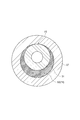
- the motor rotor 25 is an assembly including an inner sleeve 31, a permanent magnet 37, end rings 39 and 41, a protective layer 43, and a resin portion 50.
- the inner sleeve 31, the permanent magnet 37, the end rings 39, 41, the protective layer 43, and the resin portion 50 have a rotating body shape with the rotation axis H as the central axis.
- the inner sleeve 31 has a large diameter portion 33.
- the large diameter portion 33 is provided at a central portion in the axial direction of the inner sleeve 31 and has a slightly large diameter.
- the permanent magnet 37 has a cylindrical shape and is installed around the large diameter portion 33.
- the protective layer 43 is a cylindrical member and is sometimes called an "armor ring" or the like.
- the protective layer 43 has a cylindrical shape and is installed around the permanent magnet 37.
- the protective layer 43 prevents debris from scattering in the radial direction when the permanent magnet 37 is damaged. Further, the protective layer 43 needs to have a certain degree of rigidity in order to suppress the distortion of the permanent magnet 37 and reduce the possibility of damage to the permanent magnet 37.
- the permanent magnet 37 and the protective layer 43 may be connected by filling the gap between the permanent magnet 37 and the protective layer 43 with resin.
- the end rings 39 and 41 may be connected to the inner sleeve 31 and the protective layer 43 via a resin portion to be filled.
- a steel material such as SCM435H can be adopted.
- a neodymium magnet (Nd-Fe-B), a samarium cobalt magnet, or the like can be adopted.
- a metal material or a resin material can be adopted.
- a non-magnetic metal such as titanium (for example, Ti-6Al-4V) can be adopted.
- CFRP carbon fiber reinforced plastic
- the material of the end rings 39 and 41 for example, a non-magnetic metal such as SUS, a thermosetting resin, a thermoplastic resin, or the like can be adopted.
- thermosetting resin As the material of the resin portion 50 , a thermosetting resin, a thermoplastic resin, or the like can be adopted. More specifically, as the material of the resin portion 50, a phenol resin or an epoxy resin which is a thermosetting resin, or an LCP (liquid crystal polymer) which is a thermoplastic resin can be adopted. According to the tests of the present inventors, LCP is preferable as a material for the resin portion 50 in that it has higher fluidity during injection molding than the phenol resin. In addition, LCP is preferable as a material for the resin portion 50 in that it is relatively easy to obtain as compared with a phenol resin.
- the phenol resin is preferable as the material of the resin portion 50 in that it is superior in heat resistance, rigidity, and environmental resistance as compared with LCP. Further, the epoxy resin is preferable as the material of the resin portion 50 because the material itself has adhesiveness.
- FIG. 3 is a side view showing only the inner sleeve 31 and the permanent magnet 37 of the motor rotor 25.
- the feature portion according to the description is exaggerated and depicted, and the dimensional ratio of each portion may not match with other figures.
- the inner peripheral surface 38 of the permanent magnet 37 is a cylindrical inner peripheral surface.
- the inner peripheral surface 38a the inner peripheral surface of the end portion of the permanent magnet 37 in the axial direction
- the inner peripheral surface 38b the inner peripheral surface of the central portion of the permanent magnet 37 in the axial direction
- the inner sleeve 31 has a small diameter portion 61.
- the small diameter portion 61 is formed at a position facing the inner peripheral surface 38a in the radial direction.
- the small diameter portion 61 is formed to have a smaller diameter than the central portion 63 of the inner sleeve 31.
- the central portion 63 is a portion facing the inner peripheral surface 38b of the permanent magnet 37.
- the small diameter portion 61 is a tapered portion 62a.
- the tapered portion 62a is formed so that the diameter is reduced as the distance from the central portion 63 in the axial direction increases.
- the outer peripheral surface of the tapered portion 62a forms a conical surface.
- the small diameter portion 61 is not limited to the tapered portion 62a.
- the small diameter portion 61 may be a step small diameter portion 62b formed with a step between the central portion 63 and the small diameter portion 61.
- the outer peripheral surface of the step small diameter portion 62b is a cylindrical surface.
- a groove 65 extending in a direction including a circumferential component is formed on the outer peripheral surface 31a of the inner sleeve 31.
- the groove 65 includes a circumferential groove 66a and a knurled groove 66b.
- the circumferential groove 66a extends in the circumferential direction on the outer peripheral surface 31a.
- the knurled groove 66b extends spirally in two directions intersecting each other on the outer peripheral surface 31a.
- the groove 65 it is not essential that both the circumferential groove 66a and the knurled groove 66b are provided, and only one of them may be provided.
- a knurled groove formed of a spiral groove extending in one direction may be adopted.
- FIG. 5 is a cross-sectional view showing an example of the state of the mold 70 when the resin portion 50 is formed by injection molding.
- the inner sleeve 31 and the permanent magnet 37 are housed in the mold 70.
- the permanent magnet 37 is arranged around the inner sleeve 31.
- the flow state of the molten resin 71 may become non-uniform in the circumferential direction. Then, as shown in FIG. 6, the molten resin 71 may be cured in a state where the inner sleeve 31 and the permanent magnet 37 are misaligned. In this case, the resin may not spread to the portion where the gap 69 is narrowed (reference numeral 73 in the figure), resulting in a defect. Then, the above-mentioned defect may cause peeling of the resin portion 50.
- the inner sleeve 31 has a small diameter portion 61.
- the gap 69 expands in the radial direction at the position of the end portion of the permanent magnet 37 which is the inlet of the molten resin 71.
- the molten resin 71 can easily spread in the entire circumferential direction in the gap between the small diameter portion 61 and the inner peripheral surface 38a. Then, the molten resin 71 spreads in the entire circumferential direction and flows in the axial direction to fill the gap 69.
- the molten resin 71 can easily spread evenly in the circumferential direction with respect to the gap 69. As a result, the inner sleeve 31 and the permanent magnet 37 are aligned.
- the inner sleeve 31 and the permanent magnet 37 can be aligned by a simple method such as providing the inner sleeve 31 with a small diameter portion 61.
- the groove 65 formed on the outer peripheral surface 31a of the inner sleeve 31 extends in the direction including the circumferential component.
- the groove 65 guides the flow of the molten resin 71 in the direction including the circumferential component. Therefore, the groove 65 promotes the flow of the molten resin 71 in the circumferential direction in the gap 69. Therefore, the presence of the groove 65 also makes it easy for the molten resin 71 to spread evenly in the circumferential direction with respect to the gap 69.
- a space 75 is formed between the left end surface 37a of the permanent magnet 37 and the mold 70 at the time of injection molding. This space 75 functions as a resin pool and spreads the molten resin 71 in the circumferential direction. Therefore, the flow of the molten resin 71 in the circumferential direction in the gap 69 is further promoted.
- connection between the inner sleeve 31 having a hollow structure and the permanent magnet 37 has been described, but the above-mentioned structure can also be applied to, for example, connecting the permanent magnet 37 to the shaft portion of the solid structure.
Landscapes
- Engineering & Computer Science (AREA)
- Power Engineering (AREA)
- Chemical & Material Sciences (AREA)
- Combustion & Propulsion (AREA)
- Mechanical Engineering (AREA)
- General Engineering & Computer Science (AREA)
- Chemical Kinetics & Catalysis (AREA)
- General Chemical & Material Sciences (AREA)
- Permanent Field Magnets Of Synchronous Machinery (AREA)
- Iron Core Of Rotating Electric Machines (AREA)
Priority Applications (4)
| Application Number | Priority Date | Filing Date | Title |
|---|---|---|---|
| JP2021513548A JP7264238B2 (ja) | 2019-04-10 | 2020-03-24 | モーターローター |
| CN202080026173.4A CN113661636B (zh) | 2019-04-10 | 2020-03-24 | 马达转子 |
| DE112020001824.5T DE112020001824T5 (de) | 2019-04-10 | 2020-03-24 | Motorrotor |
| US17/491,560 US11664694B2 (en) | 2019-04-10 | 2021-10-01 | Motor rotor |
Applications Claiming Priority (2)
| Application Number | Priority Date | Filing Date | Title |
|---|---|---|---|
| JP2019074828 | 2019-04-10 | ||
| JP2019-074828 | 2019-04-10 |
Related Child Applications (1)
| Application Number | Title | Priority Date | Filing Date |
|---|---|---|---|
| US17/491,560 Continuation US11664694B2 (en) | 2019-04-10 | 2021-10-01 | Motor rotor |
Publications (1)
| Publication Number | Publication Date |
|---|---|
| WO2020209050A1 true WO2020209050A1 (ja) | 2020-10-15 |
Family
ID=72750684
Family Applications (1)
| Application Number | Title | Priority Date | Filing Date |
|---|---|---|---|
| PCT/JP2020/013110 Ceased WO2020209050A1 (ja) | 2019-04-10 | 2020-03-24 | モーターローター |
Country Status (5)
| Country | Link |
|---|---|
| US (1) | US11664694B2 (https=) |
| JP (1) | JP7264238B2 (https=) |
| CN (1) | CN113661636B (https=) |
| DE (1) | DE112020001824T5 (https=) |
| WO (1) | WO2020209050A1 (https=) |
Cited By (2)
| Publication number | Priority date | Publication date | Assignee | Title |
|---|---|---|---|---|
| CN115479031A (zh) * | 2021-05-31 | 2022-12-16 | 日本电产三协株式会社 | 泵装置 |
| WO2025032816A1 (ja) * | 2023-08-10 | 2025-02-13 | 三菱重工エンジン&ターボチャージャ株式会社 | 回転体および回転電機並びに電動圧縮機 |
Families Citing this family (2)
| Publication number | Priority date | Publication date | Assignee | Title |
|---|---|---|---|---|
| KR102759703B1 (ko) * | 2019-11-26 | 2025-02-03 | 삼성전자주식회사 | Bldc모터 |
| DE112021002656T5 (de) * | 2020-09-30 | 2023-03-16 | Ihi Corporation | Motorrotor und verfahren zum herstellen eines motorrotors |
Citations (8)
| Publication number | Priority date | Publication date | Assignee | Title |
|---|---|---|---|---|
| US2488729A (en) * | 1946-10-18 | 1949-11-22 | Int Harvester Co | Magneto rotor |
| JPH0294444U (https=) * | 1989-01-10 | 1990-07-26 | ||
| JPH1014147A (ja) * | 1996-06-24 | 1998-01-16 | Fuji Electric Co Ltd | 周方向着磁形回転子を持つ回転機及びその製造方法 |
| JP2002010545A (ja) * | 2000-06-23 | 2002-01-11 | Mitsubishi Electric Corp | 永久磁石回転子 |
| JP2007159191A (ja) * | 2005-12-01 | 2007-06-21 | Denso Corp | 電動機 |
| JP2011239546A (ja) * | 2010-05-10 | 2011-11-24 | Makita Corp | Dcブラシレスモータ |
| WO2012089470A2 (en) * | 2010-12-29 | 2012-07-05 | Arcelik Anonim Sirketi | Rotor part of a permanent magnet synchronous motor |
| JP2013074736A (ja) * | 2011-09-28 | 2013-04-22 | Toyota Motor Corp | 回転電機のロータ、および、これを用いた回転電機 |
Family Cites Families (24)
| Publication number | Priority date | Publication date | Assignee | Title |
|---|---|---|---|---|
| JPS6165839A (ja) | 1984-09-07 | 1986-04-04 | Nippon Petrochem Co Ltd | α−(p−イソブチルフエニル)プロピオン酸の製法 |
| JPS6165839U (https=) * | 1984-10-04 | 1986-05-06 | ||
| JPH0294444A (ja) | 1988-09-30 | 1990-04-05 | Toshiba Corp | 半導体装置の製造方法 |
| JP3398977B2 (ja) * | 1992-07-14 | 2003-04-21 | 株式会社安川電機 | 永久磁石界磁ロータ |
| JPH0799743A (ja) * | 1993-09-27 | 1995-04-11 | Hitachi Metals Ltd | 永久磁石型ロータ |
| JP3287113B2 (ja) * | 1994-05-23 | 2002-05-27 | 株式会社安川電機 | 永久磁石形回転子の製造方法 |
| JPH10201152A (ja) * | 1997-01-17 | 1998-07-31 | Mitsubishi Electric Corp | 永久磁石回転子およびその製造方法 |
| JP2000014062A (ja) | 1998-06-16 | 2000-01-14 | Denso Corp | トルクモータ |
| JP2000324769A (ja) * | 1999-05-13 | 2000-11-24 | Matsushita Electric Ind Co Ltd | ステッピングモータ |
| JP2002209352A (ja) * | 2001-01-12 | 2002-07-26 | Mitsubishi Electric Corp | 回転電機の永久磁石回転子およびその製造方法 |
| ATE418809T1 (de) * | 2002-07-26 | 2009-01-15 | Ms Technologie Gmbh | Hochgeschwindigkeitsrotor |
| JP4352766B2 (ja) * | 2003-06-09 | 2009-10-28 | 三菱電機株式会社 | 電動パワーステアリング装置用ブラシレスモータの製造方法 |
| JP3810074B2 (ja) | 2004-01-09 | 2006-08-16 | 日本サーボ株式会社 | 回転子 |
| JP2006109676A (ja) * | 2004-10-08 | 2006-04-20 | Jtekt Corp | 回転子及びこれの製造方法 |
| JP4222310B2 (ja) | 2005-01-13 | 2009-02-12 | 三菱マテリアルシ−エムアイ株式会社 | ステッピングモータ |
| KR100683595B1 (ko) * | 2005-06-21 | 2007-02-20 | 주식회사 대우일렉트로닉스 | 모터의 회전자 구조 |
| JP4893991B2 (ja) | 2005-09-06 | 2012-03-07 | 株式会社デンソー | 燃料ポンプ |
| DE102006000447A1 (de) | 2005-09-06 | 2007-03-08 | Denso Corp., Kariya | Fluidpumpe mit Lagerloch |
| JP2007116767A (ja) | 2005-10-18 | 2007-05-10 | Denso Corp | 燃料ポンプ |
| DE102006000446B4 (de) | 2005-09-06 | 2013-04-18 | Denso Corporation | Fluidpumpe und Elektromotor und deren Herstellungsverfahren |
| US9664050B2 (en) * | 2013-10-25 | 2017-05-30 | Ecomotors, Inc. | Bearings for a turbomachine having an electric motor |
| JP5820046B2 (ja) * | 2013-12-27 | 2015-11-24 | ファナック株式会社 | 磁石保持構造を備えた電動機の回転子及びそれを備える電動機 |
| JP2016208724A (ja) | 2015-04-24 | 2016-12-08 | 株式会社豊田自動織機 | ロータおよびその製造方法、ならびに電動機および圧縮機 |
| JP6402231B2 (ja) | 2017-11-09 | 2018-10-10 | 日本電産テクノモータ株式会社 | モータおよびモータの製造方法 |
-
2020
- 2020-03-24 DE DE112020001824.5T patent/DE112020001824T5/de active Pending
- 2020-03-24 JP JP2021513548A patent/JP7264238B2/ja active Active
- 2020-03-24 CN CN202080026173.4A patent/CN113661636B/zh active Active
- 2020-03-24 WO PCT/JP2020/013110 patent/WO2020209050A1/ja not_active Ceased
-
2021
- 2021-10-01 US US17/491,560 patent/US11664694B2/en active Active
Patent Citations (8)
| Publication number | Priority date | Publication date | Assignee | Title |
|---|---|---|---|---|
| US2488729A (en) * | 1946-10-18 | 1949-11-22 | Int Harvester Co | Magneto rotor |
| JPH0294444U (https=) * | 1989-01-10 | 1990-07-26 | ||
| JPH1014147A (ja) * | 1996-06-24 | 1998-01-16 | Fuji Electric Co Ltd | 周方向着磁形回転子を持つ回転機及びその製造方法 |
| JP2002010545A (ja) * | 2000-06-23 | 2002-01-11 | Mitsubishi Electric Corp | 永久磁石回転子 |
| JP2007159191A (ja) * | 2005-12-01 | 2007-06-21 | Denso Corp | 電動機 |
| JP2011239546A (ja) * | 2010-05-10 | 2011-11-24 | Makita Corp | Dcブラシレスモータ |
| WO2012089470A2 (en) * | 2010-12-29 | 2012-07-05 | Arcelik Anonim Sirketi | Rotor part of a permanent magnet synchronous motor |
| JP2013074736A (ja) * | 2011-09-28 | 2013-04-22 | Toyota Motor Corp | 回転電機のロータ、および、これを用いた回転電機 |
Cited By (2)
| Publication number | Priority date | Publication date | Assignee | Title |
|---|---|---|---|---|
| CN115479031A (zh) * | 2021-05-31 | 2022-12-16 | 日本电产三协株式会社 | 泵装置 |
| WO2025032816A1 (ja) * | 2023-08-10 | 2025-02-13 | 三菱重工エンジン&ターボチャージャ株式会社 | 回転体および回転電機並びに電動圧縮機 |
Also Published As
| Publication number | Publication date |
|---|---|
| CN113661636A (zh) | 2021-11-16 |
| JP7264238B2 (ja) | 2023-04-25 |
| JPWO2020209050A1 (https=) | 2020-10-15 |
| US11664694B2 (en) | 2023-05-30 |
| DE112020001824T5 (de) | 2021-12-23 |
| CN113661636B (zh) | 2024-04-16 |
| US20220021255A1 (en) | 2022-01-20 |
Similar Documents
| Publication | Publication Date | Title |
|---|---|---|
| US11664694B2 (en) | Motor rotor | |
| CN113678343B (zh) | 马达转子 | |
| CN101460723B (zh) | 电动增压器 | |
| CN101473515B (zh) | 马达转子以及其旋转平衡修正方法 | |
| EP3300219B1 (en) | Motor and method for manufacturing same | |
| CN101720524A (zh) | 具有同心设置的转子的电机以及具有该电机的驱动装置 | |
| US20190027979A1 (en) | Salient-pole rotor and rotor manufacturing method | |
| US12424912B2 (en) | Motor rotor with end ring | |
| JP7131457B2 (ja) | 電動機の製造方法 | |
| CN107269546A (zh) | 电子水泵 | |
| US10781823B2 (en) | Impeller and supercharger | |
| JP6255861B2 (ja) | ロータおよび電動モータ | |
| JP2007205246A (ja) | ウォータポンプおよびハイブリッド車両 | |
| US20230231431A1 (en) | Motor rotor with fractured magnet | |
| US20250183756A1 (en) | Rotor, rotary electrical machine, electric compressor, and method for producing rotor | |
| WO2022202077A1 (ja) | モータロータ及び過給機 | |
| US20250343452A1 (en) | Motor rotor with cylindrical magnet | |
| US20250167608A1 (en) | Rotor, rotary electrical machine, electric compressor, and method for producing rotor | |
| CN210431058U (zh) | 旋转电机 | |
| JP2020084939A (ja) | インペラホイール、モータ及び過給機 | |
| WO2025129571A1 (zh) | 转子总成和电机 | |
| EP3629456A1 (en) | Method for manufacturing a rotor of an electric motor | |
| WO2025032816A1 (ja) | 回転体および回転電機並びに電動圧縮機 | |
| KR20260026216A (ko) | 계자권선 형 동기모터의 샤프트 |
Legal Events
| Date | Code | Title | Description |
|---|---|---|---|
| 121 | Ep: the epo has been informed by wipo that ep was designated in this application |
Ref document number: 20787485 Country of ref document: EP Kind code of ref document: A1 |
|
| ENP | Entry into the national phase |
Ref document number: 2021513548 Country of ref document: JP Kind code of ref document: A |
|
| 122 | Ep: pct application non-entry in european phase |
Ref document number: 20787485 Country of ref document: EP Kind code of ref document: A1 |