WO2020203423A1 - 画像診断用カテーテル - Google Patents
画像診断用カテーテル Download PDFInfo
- Publication number
- WO2020203423A1 WO2020203423A1 PCT/JP2020/012777 JP2020012777W WO2020203423A1 WO 2020203423 A1 WO2020203423 A1 WO 2020203423A1 JP 2020012777 W JP2020012777 W JP 2020012777W WO 2020203423 A1 WO2020203423 A1 WO 2020203423A1
- Authority
- WO
- WIPO (PCT)
- Prior art keywords
- housing
- sheath
- transmission
- diagnostic imaging
- distal end
- Prior art date
- Legal status (The legal status is an assumption and is not a legal conclusion. Google has not performed a legal analysis and makes no representation as to the accuracy of the status listed.)
- Ceased
Links
Images


Classifications
-
- A—HUMAN NECESSITIES
- A61—MEDICAL OR VETERINARY SCIENCE; HYGIENE
- A61B—DIAGNOSIS; SURGERY; IDENTIFICATION
- A61B8/00—Diagnosis using ultrasonic, sonic or infrasonic waves
- A61B8/44—Constructional features of the ultrasonic, sonic or infrasonic diagnostic device
- A61B8/4444—Constructional features of the ultrasonic, sonic or infrasonic diagnostic device related to the probe
- A61B8/4461—Features of the scanning mechanism, e.g. for moving the transducer within the housing of the probe
- A61B8/4466—Features of the scanning mechanism, e.g. for moving the transducer within the housing of the probe involving deflection of the probe
-
- A—HUMAN NECESSITIES
- A61—MEDICAL OR VETERINARY SCIENCE; HYGIENE
- A61B—DIAGNOSIS; SURGERY; IDENTIFICATION
- A61B8/00—Diagnosis using ultrasonic, sonic or infrasonic waves
- A61B8/12—Diagnosis using ultrasonic, sonic or infrasonic waves in body cavities or body tracts, e.g. by using catheters
-
- A—HUMAN NECESSITIES
- A61—MEDICAL OR VETERINARY SCIENCE; HYGIENE
- A61B—DIAGNOSIS; SURGERY; IDENTIFICATION
- A61B1/00—Instruments for performing medical examinations of the interior of cavities or tubes of the body by visual or photographical inspection, e.g. endoscopes; Illuminating arrangements therefor
- A61B1/00147—Holding or positioning arrangements
- A61B1/00154—Holding or positioning arrangements using guiding arrangements for insertion
-
- A—HUMAN NECESSITIES
- A61—MEDICAL OR VETERINARY SCIENCE; HYGIENE
- A61B—DIAGNOSIS; SURGERY; IDENTIFICATION
- A61B8/00—Diagnosis using ultrasonic, sonic or infrasonic waves
- A61B8/08—Clinical applications
- A61B8/0891—Clinical applications for diagnosis of blood vessels
-
- A—HUMAN NECESSITIES
- A61—MEDICAL OR VETERINARY SCIENCE; HYGIENE
- A61B—DIAGNOSIS; SURGERY; IDENTIFICATION
- A61B8/00—Diagnosis using ultrasonic, sonic or infrasonic waves
- A61B8/44—Constructional features of the ultrasonic, sonic or infrasonic diagnostic device
- A61B8/4444—Constructional features of the ultrasonic, sonic or infrasonic diagnostic device related to the probe
- A61B8/445—Details of catheter construction
-
- A—HUMAN NECESSITIES
- A61—MEDICAL OR VETERINARY SCIENCE; HYGIENE
- A61B—DIAGNOSIS; SURGERY; IDENTIFICATION
- A61B8/00—Diagnosis using ultrasonic, sonic or infrasonic waves
- A61B8/44—Constructional features of the ultrasonic, sonic or infrasonic diagnostic device
- A61B8/4444—Constructional features of the ultrasonic, sonic or infrasonic diagnostic device related to the probe
- A61B8/4455—Features of the external shape of the probe, e.g. ergonomic aspects
-
- A—HUMAN NECESSITIES
- A61—MEDICAL OR VETERINARY SCIENCE; HYGIENE
- A61B—DIAGNOSIS; SURGERY; IDENTIFICATION
- A61B8/00—Diagnosis using ultrasonic, sonic or infrasonic waves
- A61B8/44—Constructional features of the ultrasonic, sonic or infrasonic diagnostic device
- A61B8/4483—Constructional features of the ultrasonic, sonic or infrasonic diagnostic device characterised by features of the ultrasound transducer
- A61B8/4494—Constructional features of the ultrasonic, sonic or infrasonic diagnostic device characterised by features of the ultrasound transducer characterised by the arrangement of the transducer elements
-
- A—HUMAN NECESSITIES
- A61—MEDICAL OR VETERINARY SCIENCE; HYGIENE
- A61B—DIAGNOSIS; SURGERY; IDENTIFICATION
- A61B1/00—Instruments for performing medical examinations of the interior of cavities or tubes of the body by visual or photographical inspection, e.g. endoscopes; Illuminating arrangements therefor
- A61B1/00064—Constructional details of the endoscope body
- A61B1/00071—Insertion part of the endoscope body
- A61B1/0008—Insertion part of the endoscope body characterised by distal tip features
- A61B1/00087—Tools
-
- A—HUMAN NECESSITIES
- A61—MEDICAL OR VETERINARY SCIENCE; HYGIENE
- A61B—DIAGNOSIS; SURGERY; IDENTIFICATION
- A61B1/00—Instruments for performing medical examinations of the interior of cavities or tubes of the body by visual or photographical inspection, e.g. endoscopes; Illuminating arrangements therefor
- A61B1/00064—Constructional details of the endoscope body
- A61B1/00071—Insertion part of the endoscope body
- A61B1/0008—Insertion part of the endoscope body characterised by distal tip features
- A61B1/00096—Optical elements
-
- A—HUMAN NECESSITIES
- A61—MEDICAL OR VETERINARY SCIENCE; HYGIENE
- A61B—DIAGNOSIS; SURGERY; IDENTIFICATION
- A61B1/00—Instruments for performing medical examinations of the interior of cavities or tubes of the body by visual or photographical inspection, e.g. endoscopes; Illuminating arrangements therefor
- A61B1/00163—Optical arrangements
- A61B1/00174—Optical arrangements characterised by the viewing angles
- A61B1/00177—Optical arrangements characterised by the viewing angles for 90 degrees side-viewing
-
- A—HUMAN NECESSITIES
- A61—MEDICAL OR VETERINARY SCIENCE; HYGIENE
- A61B—DIAGNOSIS; SURGERY; IDENTIFICATION
- A61B1/00—Instruments for performing medical examinations of the interior of cavities or tubes of the body by visual or photographical inspection, e.g. endoscopes; Illuminating arrangements therefor
- A61B1/06—Instruments for performing medical examinations of the interior of cavities or tubes of the body by visual or photographical inspection, e.g. endoscopes; Illuminating arrangements therefor with illuminating arrangements
- A61B1/07—Instruments for performing medical examinations of the interior of cavities or tubes of the body by visual or photographical inspection, e.g. endoscopes; Illuminating arrangements therefor with illuminating arrangements using light-conductive means, e.g. optical fibres
Definitions
- This disclosure relates to a catheter for diagnostic imaging.
- Patent Document 1 describes this type of diagnostic imaging catheter.
- Patent Document 1 describes an ultrasonic transducer as a signal transmitting / receiving member, which is mounted on a terminal housing as a housing.
- the housing to which the signal transmission / reception member is mounted is made of a hard and hard-to-deform material in order to stabilize the rotation axis of the transmission / reception member with respect to the rotation of the drive shaft.
- the housing is required to have a followability that can easily follow a bent blood vessel shape and move forward.
- An object of the present disclosure is to provide a diagnostic imaging catheter provided with a housing capable of improving followability to a blood vessel shape.
- the diagnostic imaging catheter as the first aspect of the present disclosure includes a sheath inserted into a living body, a drive shaft rotatable in the sheath, and an imaging core portion attached to the drive shaft in the sheath.
- the imaging core portion includes a transmission / reception member capable of transmitting / receiving signals and a housing for holding the transmission / reception member, and a side surface of the housing facing the radial direction of the sheath reaches a distal end.
- the inclined portion is provided so as to be inclined toward the central axis of the drive shaft toward the distal side, and the inclined portion is distal to the transmitting and receiving member from a side proximal to the distal end of the transmitting and receiving member. It extends to the distal side of the edge.
- the side surface of the housing includes a support surface for supporting the transmission / reception member, and the housing is viewed from the support surface side at least on one side of the transmission / reception member.
- the inclined portion is formed on the side surface of the housing located at.
- the side surface of the housing includes a support surface for supporting the transmission / reception member, and the inclined portion is formed at a position on the back side of the support surface of the side surface of the housing.
- the back side of the support surface is composed of a peripheral surface.
- the side surface of the housing is raised on the proximal side with respect to the support surface toward the inner surface of the sheath from the transmission / reception member supported by the support surface.
- Proximal ridges are provided.
- the side surface distal to the support surface is raised toward the inner surface of the sheath from the transmission / reception member supported by the support surface.
- the angle of the inclined portion with respect to the central axis increases toward the distal side.
- the transmitting / receiving member is an ultrasonic vibrator capable of transmitting / receiving ultrasonic waves on an ultrasonic transmitting / receiving surface, and the distal end surface of the ultrasonic vibrator is formed of a convex curved surface. ing.
- a diagnostic imaging catheter provided with a housing capable of improving followability to a blood vessel shape.
- FIG. 5 is a cross-sectional view showing a cross section parallel to the longitudinal direction at the distal end portion of the diagnostic imaging catheter shown in FIG. It is a lateral side view of the vicinity of the imaging core portion of the diagnostic imaging catheter shown in FIG. It is a top side view of the vicinity of the imaging core portion of the diagnostic imaging catheter shown in FIG. It is a perspective view of the vicinity of the imaging core portion of the diagnostic imaging catheter shown in FIG. It is a usage state diagram which shows the state which the image diagnostic catheter shown in FIG. 1 is inserted into a blood vessel. It is a figure which shows a specific example of an ultrasonic oscillator whose outer shape is an elliptical shape of an ultrasonic transmission / reception surface.
- the longitudinal direction of the diagnostic imaging catheter will be referred to as "longitudinal direction A".
- the side on which the diagnostic imaging catheter is inserted into the living body is described as the "distal side”
- the opposite side is described as the "proximal side”.
- the direction from the proximal side to the distal side of the diagnostic imaging catheter according to the present disclosure may be simply described as "insertion direction A1”.
- the direction from the distal side to the proximal side of the diagnostic imaging catheter 1 may be simply described as "removal direction A2".
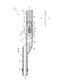
- FIG. 1 is a diagram showing a diagnostic imaging system 100 including a diagnostic imaging catheter 1 as an embodiment of the present disclosure.
- the diagnostic imaging system 100 includes a diagnostic imaging catheter 1 and a diagnostic imaging device 120.
- FIG. 1 shows a state in which the diagnostic imaging catheter 1 is connected to the diagnostic imaging apparatus 120.
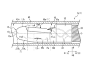
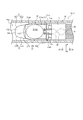
- FIG. 2 is a cross-sectional view showing a cross section parallel to the longitudinal direction A at the distal end portion which is the distal end portion of the diagnostic imaging catheter 1.
- FIG. 3 is an upper side view of the vicinity of the imaging core portion 10 of the diagnostic imaging catheter 1.
- FIG. 4 is a lateral side view of the vicinity of the imaging core portion 10 of the diagnostic imaging catheter 1.
- FIG. 5 is a perspective view of the vicinity of the imaging core portion 10 of the diagnostic imaging catheter 1. In FIG. 5, the sheath 40 is omitted.
- the diagnostic imaging catheter 1 of the present embodiment is applicable to IVUS. As shown in FIG. 1, the diagnostic imaging catheter 1 is driven by being connected to the diagnostic imaging apparatus 120. More specifically, the diagnostic imaging catheter 1 of the present embodiment is connected to the drive unit 120a of the diagnostic imaging apparatus 120.
- the diagnostic imaging catheter 1 includes an insertion portion 1a and an operation portion 1b.
- the insertion portion 1a is a portion of the diagnostic imaging catheter 1 that is inserted into the living body and used.
- the operation unit 1b is a portion of the diagnostic imaging catheter 1 that is operated in vitro with the insertion unit 1a inserted into the living body.
- the portion distal to the distal connector 62 (see FIG. 1) described later is the insertion portion 1a, and the portion proximal to the distal connector 62 is operated. Part 1b.
- the insertion portion 1a includes an imaging core portion 10, a drive shaft 20, a signal line 30, and a sheath 40.
- the imaging core portion 10 is connected to the distal side of the drive shaft 20.
- the sheath 40 is inserted and used in a living body (see FIG. 6).
- the imaging core portion 10, the drive shaft 20, and the signal line 30 are located in the sheath 40 and are inserted into the living body together with the sheath 40 for use (see FIG. 6).
- the operation unit 1b includes an inner pipe member 50 and an outer pipe member 60.
- the inner tube member 50 holds the proximal end of the drive shaft 20.
- the outer tube member 60 holds the proximal end of the sheath 40.
- the drive shaft 20 and the signal line 30 shown in FIG. 2 can move in the sheath 40 in the longitudinal direction A. it can.
- the drive shaft 20 and the signal line 30 extend through the inside of the inner pipe member 50 and the outer pipe member 60 not only in the region of the insertion portion 1a but also in the region of the operation portion 1b in the longitudinal direction A.
- Imaging core unit 10 As shown in FIG. 2, the imaging core portion 10 is located in the sheath 40 inserted into the living body.
- the imaging core unit 10 of the present embodiment includes a transmission / reception member 11 capable of transmitting / receiving signals, a housing 12 holding the transmission / reception member 11, and a contrast marker 13.
- the transmission / reception member 11 of the present embodiment is an ultrasonic vibrator 11a capable of transmitting / receiving an ultrasonic signal.
- the ultrasonic vibrator 11a as the transmission / reception member 11 will be described as an example, but the transmission / reception member 11 is not limited to the ultrasonic vibrator 11a, and may be, for example, an optical element capable of transmitting and receiving an optical signal.
- the optical element capable of transmitting and receiving an optical signal include a ball lens provided at the distal end of an optical fiber and having a lens function for condensing light and a reflection function for reflecting light.
- the ultrasonic vibrator 11a as the transmission / reception member 11 of the present embodiment includes a piezoelectric element 14, a support member 15, and an acoustic matching member 16.
- the piezoelectric element 14 is laminated on a flat piezoelectric body, a first electrode laminated on at least one side in the thickness direction of the piezoelectric body, and at least the other side in the thickness direction of the piezoelectric body. It consists of a second electrode.
- the side in which the ultrasonic wave transmitting / receiving surface 11a1 capable of transmitting / receiving ultrasonic waves of the ultrasonic vibrator 11a is located is referred to as “surface side” in the thickness direction of the piezoelectric body, and is described in the thickness direction of the piezoelectric body.
- the side of the ultrasonic transducer 11a opposite to the ultrasonic transmission / reception surface 11a1 is referred to as the "back surface side".
- the piezoelectric body of the piezoelectric element 14 is composed of, for example, a piezoelectric ceramic sheet.
- the material of the piezoelectric ceramic sheet include piezoelectric ceramic materials such as lead titanate (PZT) and lithium niobate.
- the piezoelectric material may be formed of quartz instead of the piezoelectric ceramic material.
- the first electrode and the second electrode of the piezoelectric element 14 can be formed by laminating as electrode layers on both sides of the piezoelectric body in the thickness direction by, for example, an ion plating method using a mask material, a vapor deposition method, or a sputtering method. ..
- Examples of the material of the first electrode and the second electrode include metals such as silver, chromium, copper, nickel, and gold, and laminates of these metals.
- the first electrode is laminated only on the surface side of the piezoelectric body.
- the second electrode is laminated on the back surface side of the piezoelectric body, and a part of the second electrode is folded back on the front surface side of the piezoelectric body. That is, the second electrode of the present embodiment is composed of a folded electrode.
- the first electrode and the second electrode may not be folded electrodes.
- the second electrode may not be a folded electrode, but a part of the first electrode may be composed of a folded electrode folded back to the back surface side.
- the support member 15 supports the piezoelectric element 14 from the back surface side of the piezoelectric element. Specifically, the support member 15 is laminated on the piezoelectric element 14 so as to cover the entire area on the back surface side of the piezoelectric element 14. As a result, ultrasonic waves from the piezoelectric element 14 that become noise can be absorbed. That is, the support member 15 of the present embodiment constitutes a sound absorbing layer that absorbs ultrasonic waves of the piezoelectric element 14.
- the sound absorbing layer as the support member 15 can be formed by a method of laminating a sheet material forming the sound absorbing layer to the piezoelectric element 14, a method of applying a liquid sound absorbing material forming the sound absorbing layer and curing it, or the like. ..
- Examples of the material of the support member 15 include rubber and an epoxy resin in which a metal powder such as tungsten powder is dispersed.
- the acoustic matching member 16 is laminated so as to cover the surface side of the piezoelectric element 14. More specifically, the acoustic matching member 16 of the present embodiment covers the entire surface side of the piezoelectric element 14 except for the portion of the piezoelectric element 14 where the signal line 30 is connected to the first electrode and the second electrode. It is laminated on.
- the propagation efficiency of ultrasonic waves to the subject can be improved. That is, the acoustic matching member 16 of the present embodiment constitutes an acoustic matching layer that enhances the propagation efficiency of ultrasonic waves.
- the acoustic matching layer as the acoustic matching member 16 is formed by a method in which a sheet material forming the acoustic matching layer is attached to the piezoelectric element 14, a method in which a liquid acoustic matching material forming the acoustic matching layer is applied and cured, and the like. Can be formed.
- the material of the acoustic matching member 16 include a resin material such as an epoxy resin.
- the acoustic matching member 16 may be composed of a laminated body of resin layers made of a resin material.
- the ultrasonic transmission / reception surface 11a1 of the ultrasonic vibrator 11a as the transmission / reception member 11 of the present embodiment is composed of the surface of the ultrasonic vibrator 11a. That is, in the ultrasonic vibrator 11a of the present embodiment, the acoustic matching member 16 constitutes a planar ultrasonic transmission / reception surface 11a1.
- the ultrasonic oscillator 11a as the transmission / reception member 11 of the present embodiment has an elliptical outer shape in a plan view in the thickness direction of the piezoelectric body, that is, in a plan view of the ultrasonic wave transmission / reception surface 11a1. .. The details will be described later.
- the housing 12 holds the ultrasonic vibrator 11a as the transmission / reception member 11 in the sheath 40.
- the proximal side of the housing 12 is connected to the drive shaft 20.
- the side surface of the housing 12 facing the radial direction B of the sheath 40 is inclined so as to approach the central axis O of the drive shaft 20 toward the distal side up to the distal end.
- the inclined portion 71 is provided.
- the “side surface of the housing” means a surface of the housing that faces the radial direction B of the sheath and constitutes the entire periphery of the radial direction B of the sheath.
- the side surface of the housing 12 of the present embodiment includes a support surface 12a that supports the ultrasonic vibrator 11a as the transmission / reception member 11. Details of the side surface of the housing 12 will be described later.
- the housing 12 of the present embodiment includes a main body portion 12b, a distal end portion 12c, and a proximal end portion 12d.
- the main body 12b includes the support surface 12a described above.
- the distal end 12c is located distal to the body 12b and includes the distal end.
- the proximal end portion 12d is located proximal to the main body portion 12b and is connected to the contrast marker 13. Details of each part of the housing 12 will be described later.
- the housing 12 can be made of a resin such as polycarbonate.
- the housing 12 is formed, for example, by injection molding a resin material.
- the housing 12 may be made of metal.
- Such a housing 12 can be made of, for example, stainless steel, gold-plated stainless steel, a platinum iridium alloy, a platinum zirconia alloy, or the like.
- such a housing 12 is formed by carving from a metal block, MIM (metal powder injection molding), or the like.
- the housing 12 may be composed of ceramics prepared by firing zirconia or the like.
- the contrast marker 13 has a substantially cylindrical outer shape and is connected to the proximal end 12d of the housing 12 on the distal side.
- the proximal end portion 12d of the housing 12 is inserted into the contrast marker 13, and the two are adhered to each other with an adhesive or the like.
- the connection configuration of the housing 12 and the contrast marker 13 is not limited to the above configuration.
- the contrast marker 13 can be configured by, for example, a metal coil or a metal pipe having high X-ray impermeableness such as platinum, gold, iridium, and tungsten.
- an absorption member 18 formed of the same material as the support member 15 described above is arranged inside the substantially cylindrical contrast marker 13 of the present embodiment.
- an absorption member 18 formed of the same material as the support member 15 described above is arranged inside the substantially cylindrical contrast marker 13 of the present embodiment.
- the imaging core portion 10 of the present embodiment is configured to include the contrast marker 13 on the proximal side of the housing 12, but may be an imaging core portion without the contrast marker 13. That is, the proximal end portion 12d of the housing 12 may be connected to the drive shaft 20 described later without the intervention of the contrast marker 13.
- the housing 12 itself may be formed of a material having contrast, such as a metal, a resin containing a material having high X-ray opacity, or ceramics. ..
- the drive shaft 20 is rotatable around the central axis O within the sheath 40. Further, the above-mentioned imaging core portion 10 is attached to the drive shaft 20 in the sheath 40. Therefore, the drive shaft 20 rotates the imaging core portion 10 around the central axis O in the sheath 40. More specifically, the drive shaft 20 rotates around the central axis O in the sheath to rotate the connected transmission / reception member 11, the housing 12, and the contrast marker 13 around the central axis O.
- the power source for rotating the drive shaft 20 is the motor 121 (see FIG. 1) of the diagnostic imaging apparatus 120, which will be described later.
- the drive shaft 20 is made of a flexible tubular body. Inside the drive shaft 20, a signal line 30 connected to the ultrasonic vibrator 11a as the transmission / reception member 11 is arranged.
- the drive shaft 20 is composed of, for example, a multi-layer coil having different winding directions around the shaft. Examples of the coil material include stainless steel and Ni—Ti (nickel / titanium) alloys.
- the drive shaft 20 passes through the inside of the inner pipe member 50 and the outer pipe member 60, and extends to a hub 52, which will be described later, located at the proximal end of the inner pipe member 50. That is, the drive shaft 20 extends from the distal end of the insertion portion 1a to the proximal end of the operation portion 1b in the longitudinal direction A.
- the signal line 30 extends in the drive shaft 20 and electrically or optically connects the transmission / reception member 11 and the diagnostic imaging apparatus 120.
- the signal line 30 of the present embodiment is an electric signal line that electrically connects the ultrasonic vibrator 11a as the transmission / reception member 11 and the diagnostic imaging apparatus 120.
- the electric signal line as the signal line 30 of the present embodiment extends from the distal end of the insertion portion 1a to the proximal end of the operation portion 1b in the longitudinal direction A.
- a plurality of electric signal lines (two in this embodiment) as the signal lines 30 of the present embodiment are provided, and are connected to the first electrode and the second electrode of the ultrasonic oscillator 11a described above, respectively.
- the plurality of electric signal lines as the signal lines 30 are composed of, for example, a twisted pair cable in which two electric signal lines are twisted.
- the signal line 30 of the present embodiment is an electric signal line, but when the transmission / reception member 11 has a configuration capable of transmitting / receiving an optical signal, the signal line 30 can be configured by, for example, an optical fiber line.
- the sheath 40 partitions the first hollow portion 41a and the second hollow portion 41b.
- the imaging core portion 10, the drive shaft 20, and the signal line 30 are housed in the first hollow portion 41a.
- the imaging core portion 10, the drive shaft 20, and the signal line 30 can move forward and backward in the longitudinal direction A in the first hollow portion 41a.
- a guide wire W can be inserted into the second hollow portion 41b.
- the tubular guide wire insertion portion 40b that partitions the second hollow portion 41b is substantially parallel to each other with respect to the distal end portion of the tubular main body portion 40a that partitions the first hollow portion 41a. It is located so that it becomes.
- the main body portion 40a and the guide wire insertion portion 40b can be formed by joining different pipe members by heat fusion or the like, but the forming method is not limited to this.
- the main body 40a is provided with a marker portion 42 having X-ray contrast property, which is formed of a material that is opaque to X-rays. Further, the guide wire insertion portion 40b is also provided with a marker portion 43 having X-ray contrast property.
- the marker portions 42 and 43 can be configured by, for example, a metal coil or a metal pipe having high X-ray impermeable properties such as platinum, gold, iridium, and tungsten.
- a window portion 44 formed in which the transparency of ultrasonic waves is higher than that of other parts is formed. More specifically, the window portion 44 of the present embodiment is formed on the main body portion 40a of the sheath 40.
- the window portion 44 of the main body portion 40a and the guide wire insertion portion 40b are formed of a flexible material, and the material is not particularly limited.
- the constituent material include various thermoplastic elastomers such as polyethylene, styrene, polyolefin, polyurethane, polyester, polyamide, polyimide, polybutadiene, transpolyisoprene, fluororubber, and chlorinated polyethylene, and one of them.
- a polymer alloy in which two or more kinds are combined, a polymer blend, a laminate, or the like can also be used.
- the proximal side of the main body 40a with respect to the window 44 has a reinforcing portion reinforced with a material having a higher rigidity than the window 44.
- the reinforcing portion is formed by disposing a reinforcing material in which a metal wire such as stainless steel is braided in a mesh shape on a flexible tubular member such as a resin.
- the tubular member can be formed of the same material as the window portion 44.
- hydrophilic lubricating coating layer that exhibits lubricity when wet on the outer surface of the sheath 40.
- a communication hole 46 that communicates the inside and the outside of the first hollow portion 41a is formed. At the time of priming, the gas in the main body 40a can be discharged through the communication hole 46.
- the inner pipe member 50 includes an inner pipe 51 and a hub 52.
- the inner pipe 51 is inserted in the outer pipe member 60 so as to be movable back and forth.
- the hub 52 is provided on the proximal side of the inner tube 51.
- the outer tube member 60 includes an outer tube 61, a distal connector 62, and a proximal connector 63.
- the outer pipe 61 is located outside the inner pipe 51 in the radial direction (the same direction as the radial direction B of the sheath 40), and the inner pipe 51 moves back and forth in the outer pipe 61.
- the distal connector 62 connects the proximal end of the sheath 40 body 40a to the distal end of the outer tube 61.
- the proximal side connector 63 is provided at the proximal end of the outer tube 61 and is configured to receive the inner tube 51 into the outer tube 61.
- the drive shaft 20 and the signal line 30 described above are the inside of the outer tube member 60 connected to the proximal side of the main body 40a from the first hollow portion 41a of the main body 40a of the sheath 40, and the outer tube member. It extends through the interior of the inner tube member 50, which is partially inserted into the 60, to the hub 52 located at the proximal end of the inner tube member 50.
- the above-mentioned imaging core portion 10 is integrally connected to the inner tube member 50 via a drive shaft 20. Therefore, when the inner pipe member 50 is pushed in the insertion direction A1, the inner pipe member 50 is pushed into the outer pipe member 60 in the insertion direction A1. When the inner tube member 50 is pushed into the outer tube member 60 in the insertion direction A1, the imaging core portion 10 connected to the inner tube member 50 via the drive shaft 20 is connected to the main body portion 40a of the sheath 40. The inside is moved in the insertion direction A1. On the contrary, when the inner pipe member 50 is pulled in the pulling direction A2, the inner pipe member 50 is pulled out from the outer pipe member 60 in the pulling direction A2. When the inner tube member 50 is pulled out from the outer tube member 60 in the removal direction A2, the imaging core portion 10 connected to the inner tube member 50 via the drive shaft 20 moves into the main body portion 40a of the sheath 40. Move in the removal direction A2.
- a connector portion that is mechanically and electrically connected to the diagnostic imaging apparatus 120 is provided. That is, the diagnostic imaging catheter 1 is mechanically and electrically connected to the diagnostic imaging apparatus 120 by a connector portion provided on the hub 52 of the inner tube member 50. More specifically, the electric signal line as the signal line 30 of the diagnostic imaging catheter 1 extends from the ultrasonic vibrator 11a to the connector portion of the hub 52. The electric signal line as the signal line 30 electrically connects the ultrasonic vibrator 11a and the diagnostic imaging device 120 with the connector portion of the hub 52 connected to the diagnostic imaging device 120. The received signal in the ultrasonic vibrator 11a is transmitted to the diagnostic imaging apparatus 120 via the connector portion of the hub 52, subjected to predetermined processing, and displayed as an image.
- the diagnostic imaging apparatus 120 includes a motor 121 which is a power source for rotating the drive shaft 20 and a motor 122 which is a power source for moving the drive shaft 20 in the longitudinal direction A. Have. The rotational motion of the motor 122 is converted into axial motion by the ball screw 123 connected to the motor 122.
- the diagnostic imaging apparatus 120 of the present embodiment includes a drive unit 120a, a control device 120b, and a monitor 120c.
- the control device 120b is electrically connected to the drive unit 120a by wire or wirelessly.
- the monitor 120c can display an image generated by the control device 120b based on the received signal received from the diagnostic imaging catheter 1.
- the motor 121, the motor 122, and the ball screw 123 described above in this embodiment are provided in the drive unit 120a.
- the operation of the drive unit 120a is controlled by the control device 120b.
- the control device 120b can be configured by a processor including a CPU and a memory.
- the diagnostic imaging apparatus 120 is not limited to the configuration shown in this embodiment, and may be configured to further include, for example, an external input unit such as a keyboard.
- FIG. 6 is a usage state diagram showing a state in which the diagnostic imaging catheter 1 of the present embodiment is inserted into the blood vessel BV.
- the features of the housing 12 of the imaging core portion 10 of the diagnostic imaging catheter 1 will be described with reference to FIGS. 2 to 6.
- the sheath 40 of the diagnostic imaging catheter 1 is inserted into a living body and used.
- the imaging core portion 10 and the drive shaft 20 are housed in the sheath 40, and the imaging core portion 10 and the drive shaft 20 are inserted into the living body together with the sheath 40 for use.
- the side surface of the housing 12 facing the radial direction B of the sheath 40 approaches the central axis O of the drive shaft 20 toward the distal end until it reaches the distal end.
- the inclined portion 71 is provided.
- the inclined portion 71 extends from the proximal side of the distal end 11a2 of the ultrasonic vibrator 11a as the transmission / reception member 11 to the distal side of the distal end 11a2 of the ultrasonic vibrator 11a as the transmission / reception member 11. Exists.
- the side surface of the housing 12 of the present embodiment includes the inclined portion 71, so that the housing 12 extends along the bent blood vessel shape. Easy to make surface contact with the inner surface of the housing. As a result, the housing 12 tends to move back and forth along the inner wall of the blood vessel BV (see FIG. 6).
- the housing 12 of the present embodiment includes a main body portion 12b, a distal end portion 12c, and a proximal end portion 12d.
- a substantially elliptical columnar recess is formed in the main body 12b.
- the ultrasonic vibrator 11a as the transmission / reception member 11 is held in the housing 12 by accommodating the back surface side on which the support member 15 is arranged in the recess and supporting the ultrasonic vibrator 11a on the bottom surface of the recess. Therefore, the support surface 12a of the transmission / reception member 11 of the housing 12 of the present embodiment is composed of the bottom surface of the recess.
- the ultrasonic vibrator 11a of the present embodiment is adhered to the housing 12 with an adhesive or the like while being housed in the recess.
- a through hole 12b1 penetrating to the outside is formed in the vicinity of the bottom surface of the recess formed in the main body portion 12b of the housing 12.
- the excess adhesive that adheres the ultrasonic vibrator 11a and the housing 12 leaks to the outside through the through hole 12b1. Therefore, it is possible to prevent the adhesive from leaking from the side wall of the recess to the surface side of the ultrasonic vibrator 11a. Therefore, it is possible to prevent the adhesive from adhering to the ultrasonic transmission / reception surface 11a1 of the ultrasonic vibrator 11a.
- the upper side view (see FIG. 4) of the housing 12 viewed from the support surface 12a side means a side view of the housing 12 viewed from the support surface 12a side in the radial direction B of the sheath 40.
- the upper side view of the housing 12 as viewed from the support surface 12a side is simply referred to as "upper side view of the housing 12".
- inclined portions 71 are formed on the side surfaces of the housing 12 located on both sides of the transmission / reception member 11, but the present invention is not limited to this configuration.
- the inclined portion 71 may be formed on the side surface of the housing 12 located on at least one side of the transmission / reception member 11.
- the side surfaces of the housing 12 located on both sides of the transmission / reception member 11 in the upper side view (see FIG. 4) of the housing 12 as in the present embodiment it is preferable that the inclined portion 71 is formed therein.
- the inclined portion 71 is also formed at the position on the back side of the support surface 12a among the side surfaces of the housing 12. Specifically, in the lateral view of the housing 12 shown in FIG. 3, an inclined portion 71 is formed at a position on the back side of the support surface 12a on the side surface of the housing 12. By providing such an inclined portion 71, it is possible to improve the followability of the housing 12 to the blood vessel shape.
- the lateral side view of the housing 12 means a side view seen from a viewpoint in which the support surface 12a of the housing 12 looks linear in the radial direction B of the sheath 40.
- the ultrasonic transmission / reception surface 11a1 of the ultrasonic vibrator 11a as the transmission / reception member 11 looks linear in the lateral view of the housing 12.
- inclined portions 71 are provided at positions on both sides of the housing 12 so as to sandwich the ultrasonic vibrator 11a as the transmission / reception member 11 in the upper side view (see FIG. 4). ing. Further, on the side surface of the housing 12 of the present embodiment, an inclined portion 71 is provided at a position on the back side of the support surface 12a in a lateral view of the housing 12 (see FIG. 3).
- the inclined portion 71 is formed in the entire circumferential region of the housing 12 from the position on the back side of the support surface 12a to the position on the other side sandwiching the ultrasonic vibrator 11a in the upper side view (see FIG. 4) of the housing 12. It is formed. By doing so, the followability of the housing 12 to the blood vessel shape can be further improved.
- the angle of the inclined portion 71 with respect to the central axis O of the drive shaft 20 increases toward the distal side in the side view of the housing 12 (see FIGS. 3 and 4).
- the inclined portion 71 of the present embodiment has the proximal inclined portion 71a and the inclined portion 71 with respect to the central axis O of the drive shaft 20 rather than the proximal inclined portion 71a in the side view shown in FIGS.
- the distal inclined portion 71b which increases the angle of the above, is provided.
- the proximal inclined portion 71a extends substantially linearly in the side view (see FIGS. 3 and 4) of the housing 12.
- proximal inclined portion 71a extends over the proximal side and the distal side of the distal end 11a2 of the transmission / reception member 11.
- the distal inclined portion 71b is curved and extends in a convex shape in a lateral view (see FIGS. 3 and 4) of the housing 12.
- the distal tilted portion 71b is continuous with the distal end of the proximal tilted portion 71a and extends to the distal end face 12e of the housing 12.
- the distal end surface 12e of the housing 12 is configured by a plane orthogonal to the central axis O of the drive shaft 20, but is not limited to this configuration, and may be, for example, a curved surface projecting radially to the distal side. Good.
- the inclined portion 71 on the side surface of the housing 12 is formed by a proximal inclined portion 71a extending linearly and a distal inclined portion 71b curved in a convex shape in a side view (see FIGS. 3 and 4). It is configured, but is not limited to this configuration.
- the inclined portion may be curved and extended so that the angle of the drive shaft 20 with respect to the central axis O gradually increases toward the distal side.
- the inclined portion 71 of the present embodiment is formed from the main body portion 12b of the housing 12 to the distal end portion 12c. More specifically, the inclined portion 71 of the present embodiment is formed only on the distal side of the proximal end 11a3 of the transmission / reception member 11, and is formed on the proximal side from the proximal end 11a3 of the transmission / reception member 11. Not. That is, the inclined portion 71 on the side surface of the housing 12 of the present embodiment is not formed at the proximal end portion 12d of the housing 12. However, the inclined portion may extend from the distal end of the housing 12 to the proximal side of the proximal end 11a3 of the transmission / reception member 11.
- the back side of the support surface 12a is composed of a peripheral surface. More specifically, of the side surfaces of the housing 12 of the present embodiment, the back side of the support surface 12a is formed by a peripheral surface along the inner peripheral surface of the sheath 40. Therefore, it is easy to make surface contact with the inner surface of the sheath 40, it is difficult to damage the inner surface of the sheath 40, and it is difficult to get caught in the inner surface of the sheath 40, and it is possible to improve the followability of the housing 12 to the blood vessel shape. Further, as described above, in the present embodiment, from the position of one side of the side surface of the housing 12 that sandwiches the ultrasonic vibrator 11a in the upper side view (see FIG.
- the lateral side view of the housing 12 In the entire circumferential region of the housing 12 from the position on the back side of the support surface 12a (see FIG. 3) to the position on the other side sandwiching the ultrasonic vibrator 11a in the upper side view of the housing 12 (see FIG. 4).
- An inclined portion 71 is formed. That is, of the side surfaces of the housing 12 of the present embodiment, the back side of the support surface 12a is a peripheral surface and an inclined portion 71 is formed. Therefore, the followability of the housing 12 to the blood vessel shape can be further improved.
- the distal end 12c of the housing 12 of the present embodiment has a substantially truncated cone shape.
- the side surface of the distal end 12c is a tapered surface that shrinks in diameter from the proximal side to the distal side. Then, a part of the tapered surface of the distal end portion 12c extends continuously in the main body portion 12b and extends to the proximal side of the distal end 11a2 of the ultrasonic vibrator 11a as the transmission / reception member 11.
- the above-mentioned inclined portion 71 on the side surface of the housing 12 is formed.
- the housing 12 of the present embodiment is located on the distal side of the main body portion 12b having a support surface 12a for supporting the transmission / reception member 11 and the main body portion 12b, and includes the distal end. It comprises a distal end 12c.
- the side surface of the housing 12 extends over the main body portion 12b and the distal end portion 12c, and includes a peripheral surface portion formed by a peripheral surface along the inner surface of the sheath 40. This peripheral surface portion is formed by the above-mentioned inclined portion 71 that approaches the central axis O of the drive shaft 20 from the proximal side to the distal side.
- the side proximal to the support surface 12a is raised toward the inner surface of the sheath 40 from the transmission / reception member 11 supported by the support surface 12a.
- a proximal ridge 17a is provided.
- the transmission / reception member 11 supported by the support surface 12a is raised toward the inner surface of the sheath 40.
- a distal ridge 17b is provided.
- the distal ridge 17b is more bulged toward the inner surface of the sheath 40 than the proximal ridge 17a.
- the distal ridge portion 17b of the present embodiment is inclined so as to approach the central axis O of the drive shaft 20 toward the distal side in the lateral view of the housing 12 (see FIG. 3). Further, in the lateral view of the housing 12 (see FIG. 3), the angle of the distal ridge 17b with respect to the central axis O of the drive shaft 20 increases toward the distal side and extends to the distal end surface 12e of the housing 12. Exists. By providing such a distal ridge portion 17b, the followability of the housing 12 to the blood vessel shape can be further improved.
- the transmission / reception member 11 of the present embodiment is an ultrasonic vibrator 11a capable of transmitting / receiving ultrasonic waves on the ultrasonic transmission / reception surface 11a1.
- the distal end surface 11a4 including the distal end 11a2 of the ultrasonic vibrator 11a is preferably formed of a convex curved surface.
- the ultrasonic vibrator 11a of the present embodiment has an elliptical outer shape when viewed from the front of the ultrasonic transmission / reception surface 11a1, but is not limited to this configuration.
- the ultrasonic oscillator may have an outer shape such as a circular shape when viewed from the front of the ultrasonic transmitting and receiving surface, and a substantially quadrangular shape where only the distal end surface is a convex curved surface when viewed from the front of the ultrasonic transmitting and receiving surface. ..
- the outer shape of the ultrasonic transmission / reception surface 11a1 is preferably elliptical or circular, and particularly preferably circular.
- the area of the ultrasonic transmission / reception surface 11a1 of the ultrasonic vibrator 11a is to realize a high output of ultrasonic waves. It is preferable to increase. Therefore, in the upper side view of the housing 12 (see FIG. 4), the side surfaces of the housing 12 on both sides of the ultrasonic vibrator 11a as the transmission / reception member 11 tend to be located close to the inner surface of the sheath 40.
- the distal end faces 11a4 of the ultrasonic transducer 11a are formed of a convex curved surface, and the housings on both sides sandwiching the ultrasonic transducer 11a in the upper side view of the housing 12 (see FIG. 4).
- An inclined portion 71 is provided on the side surface of the ultrasonic vibrator 11a so as to be along the curved surface of the distal end surface 11a4 of the ultrasonic vibrator 11a.
- the outer shape of the ultrasonic transmission / reception surface 211a1 has an elliptical shape.
- a part of the ultrasonic transducer 211a on the proximal side of the piezoelectric element 214 is located at a position that does not overlap with the ultrasonic transmission / reception surface 211a1 in the front view of the ultrasonic transmission / reception surface 211a1.
- a contact portion between the first electrode and the second electrode to which the signal line 30 is electrically connected is provided in a portion of the piezoelectric element 214 that does not overlap with the ultrasonic transmission / reception surface 211a1.
- the convergence performance of the ultrasonic waves from the ultrasonic transmission / reception surface 211a1 can be improved as compared with the ultrasonic vibrator 11a described above.
- the diagnostic imaging catheter according to the present disclosure is not limited to the specific configuration specified in the above-described embodiment, and can be variously modified or modified as long as it does not deviate from the description of the claims.
- the imaging core unit 10 of the above-described embodiment has a configuration in which only the ultrasonic vibrator 11a capable of transmitting and receiving ultrasonic signals is provided as the transmission / reception member 11, but the configuration is not limited to this.
- the transmission / reception member 11 may be, for example, an optical element capable of transmitting / receiving an optical signal, which enables optical coherence tomography (abbreviated as “OCT”).
- This disclosure relates to a catheter for diagnostic imaging.
- Imaging catheter 1a Insertion unit 1b: Operation unit 10: Imaging core unit 11: Transmission / reception member 11a: Ultrasonic transducer 11a 1: Ultrasonic transmission / reception surface 11a2: Distal end of transmission / reception member 11a3: Proximal to transmission / reception member End 11a4: Distal end surface of ultrasonic transducer 12: Housing 12a: Support surface 12b: Main body 12b1: Through hole 12c: Distal end 12d: Proximal end 12e: Distal end surface 13: Contrast marker 14: Piezoelectric Element 15: Support member 16: Acoustic matching member 17a: Proximal ridge 17b: Distal ridge 18: Absorption member 20: Drive shaft 30: Signal line 40: Sheath 40a: Main body 40b: Guide wire insertion portion 41a: First 1 Hollow part 41b: Second hollow part 42: Marker part 43: Marker part 44: Window part 46: Communication hole 50: Inner pipe member 51: Inner pipe 52: Hub 60: Outer pipe member 61:
Landscapes
- Health & Medical Sciences (AREA)
- Life Sciences & Earth Sciences (AREA)
- Surgery (AREA)
- Medical Informatics (AREA)
- Biophysics (AREA)
- Pathology (AREA)
- Radiology & Medical Imaging (AREA)
- Engineering & Computer Science (AREA)
- Biomedical Technology (AREA)
- Heart & Thoracic Surgery (AREA)
- Physics & Mathematics (AREA)
- Molecular Biology (AREA)
- Nuclear Medicine, Radiotherapy & Molecular Imaging (AREA)
- Animal Behavior & Ethology (AREA)
- General Health & Medical Sciences (AREA)
- Public Health (AREA)
- Veterinary Medicine (AREA)
- Vascular Medicine (AREA)
- Optics & Photonics (AREA)
- Gynecology & Obstetrics (AREA)
- Ultra Sonic Daignosis Equipment (AREA)
Priority Applications (4)
| Application Number | Priority Date | Filing Date | Title |
|---|---|---|---|
| JP2021511483A JP7313431B2 (ja) | 2019-03-29 | 2020-03-23 | 画像診断用カテーテル |
| CN202080024728.1A CN113631099B (zh) | 2019-03-29 | 2020-03-23 | 图像诊断用导管 |
| EP20784417.6A EP3932325B1 (en) | 2019-03-29 | 2020-03-23 | Image diagnosis catheter |
| US17/488,983 US20220015740A1 (en) | 2019-03-29 | 2021-09-29 | Diagnostic imaging catheter |
Applications Claiming Priority (2)
| Application Number | Priority Date | Filing Date | Title |
|---|---|---|---|
| JP2019-068660 | 2019-03-29 | ||
| JP2019068660 | 2019-03-29 |
Related Child Applications (1)
| Application Number | Title | Priority Date | Filing Date |
|---|---|---|---|
| US17/488,983 Continuation US20220015740A1 (en) | 2019-03-29 | 2021-09-29 | Diagnostic imaging catheter |
Publications (1)
| Publication Number | Publication Date |
|---|---|
| WO2020203423A1 true WO2020203423A1 (ja) | 2020-10-08 |
Family
ID=72668900
Family Applications (1)
| Application Number | Title | Priority Date | Filing Date |
|---|---|---|---|
| PCT/JP2020/012777 Ceased WO2020203423A1 (ja) | 2019-03-29 | 2020-03-23 | 画像診断用カテーテル |
Country Status (5)
| Country | Link |
|---|---|
| US (1) | US20220015740A1 (https=) |
| EP (1) | EP3932325B1 (https=) |
| JP (1) | JP7313431B2 (https=) |
| CN (1) | CN113631099B (https=) |
| WO (1) | WO2020203423A1 (https=) |
Cited By (1)
| Publication number | Priority date | Publication date | Assignee | Title |
|---|---|---|---|---|
| JP2023144742A (ja) * | 2022-03-28 | 2023-10-11 | テルモ株式会社 | 画像診断用カテーテル |
Families Citing this family (2)
| Publication number | Priority date | Publication date | Assignee | Title |
|---|---|---|---|---|
| US12495974B2 (en) | 2021-12-31 | 2025-12-16 | Boston Scientific Scimed, Inc. | Systems and methods for vascular image co-registration |
| CN119522073A (zh) | 2022-05-06 | 2025-02-25 | 波士顿科学国际有限公司 | 血管内成像装置 |
Citations (4)
| Publication number | Priority date | Publication date | Assignee | Title |
|---|---|---|---|---|
| JP2002005822A (ja) * | 2000-06-21 | 2002-01-09 | Olympus Optical Co Ltd | 光プローブ装置 |
| JP2006198425A (ja) | 1994-10-13 | 2006-08-03 | Boston Scientific Ltd | 内部照明超音波像形成カテーテル |
| JP2015515918A (ja) * | 2012-05-11 | 2015-06-04 | ヴォルカノ コーポレイションVolcano Corporation | 撮像及び血流測定のための超音波カテーテル |
| JP2017153621A (ja) * | 2016-02-29 | 2017-09-07 | テルモ株式会社 | 医療用デバイス |
Family Cites Families (14)
| Publication number | Priority date | Publication date | Assignee | Title |
|---|---|---|---|---|
| US6036648A (en) * | 1998-10-23 | 2000-03-14 | Scimed Life Systems, Inc. | Machine tilt transducer and methods of making |
| JP2003169806A (ja) * | 2001-12-05 | 2003-06-17 | Olympus Optical Co Ltd | 超音波探触子 |
| JP3894092B2 (ja) * | 2002-10-18 | 2007-03-14 | フジノン株式会社 | 超音波内視鏡 |
| CN113520315A (zh) * | 2007-01-19 | 2021-10-22 | 桑尼布鲁克健康科学中心 | 具有组合的超声和光学成像装置的成像探头 |
| JP5399301B2 (ja) * | 2010-03-12 | 2014-01-29 | テルモ株式会社 | カテーテル |
| WO2013145689A1 (ja) * | 2012-03-28 | 2013-10-03 | テルモ株式会社 | プローブ及び画像診断装置 |
| US20140257102A1 (en) * | 2013-03-07 | 2014-09-11 | Volcano Corporation | Devices, Systems, and Methods for Dual Image Intravascular Ultrasound |
| JP6606171B2 (ja) * | 2014-08-28 | 2019-11-13 | コーニンクレッカ フィリップス エヌ ヴェ | 補強高速交換ポートを有する血管内装置及び関連システム |
| JP6010259B1 (ja) * | 2014-11-21 | 2016-10-19 | オリンパス株式会社 | 超音波振動子、超音波内視鏡 |
| US10973491B2 (en) * | 2015-06-12 | 2021-04-13 | Koninklijke Philips N.V. | Interconnects for intravascular ultrasound (IVUS) devices |
| JP6542102B2 (ja) * | 2015-11-09 | 2019-07-10 | 富士フイルム株式会社 | 内視鏡 |
| JP6663997B2 (ja) * | 2016-08-04 | 2020-03-13 | オリンパス株式会社 | 超音波振動子モジュールの製造方法および超音波内視鏡 |
| US11819360B2 (en) * | 2017-08-15 | 2023-11-21 | Koninklijke Philips N.V. | Intraluminal rotational ultrasound for diagnostic imaging and therapy |
| CA3108429A1 (en) * | 2018-08-08 | 2020-02-13 | Craniovation, Inc. | Tissue treatment with sensitizer and light and/or sound |
-
2020
- 2020-03-23 CN CN202080024728.1A patent/CN113631099B/zh active Active
- 2020-03-23 WO PCT/JP2020/012777 patent/WO2020203423A1/ja not_active Ceased
- 2020-03-23 JP JP2021511483A patent/JP7313431B2/ja active Active
- 2020-03-23 EP EP20784417.6A patent/EP3932325B1/en active Active
-
2021
- 2021-09-29 US US17/488,983 patent/US20220015740A1/en active Pending
Patent Citations (4)
| Publication number | Priority date | Publication date | Assignee | Title |
|---|---|---|---|---|
| JP2006198425A (ja) | 1994-10-13 | 2006-08-03 | Boston Scientific Ltd | 内部照明超音波像形成カテーテル |
| JP2002005822A (ja) * | 2000-06-21 | 2002-01-09 | Olympus Optical Co Ltd | 光プローブ装置 |
| JP2015515918A (ja) * | 2012-05-11 | 2015-06-04 | ヴォルカノ コーポレイションVolcano Corporation | 撮像及び血流測定のための超音波カテーテル |
| JP2017153621A (ja) * | 2016-02-29 | 2017-09-07 | テルモ株式会社 | 医療用デバイス |
Cited By (2)
| Publication number | Priority date | Publication date | Assignee | Title |
|---|---|---|---|---|
| JP2023144742A (ja) * | 2022-03-28 | 2023-10-11 | テルモ株式会社 | 画像診断用カテーテル |
| JP7825482B2 (ja) | 2022-03-28 | 2026-03-06 | テルモ株式会社 | 画像診断用カテーテル |
Also Published As
| Publication number | Publication date |
|---|---|
| EP3932325A1 (en) | 2022-01-05 |
| JP7313431B2 (ja) | 2023-07-24 |
| JPWO2020203423A1 (https=) | 2020-10-08 |
| EP3932325A4 (en) | 2022-04-20 |
| CN113631099A (zh) | 2021-11-09 |
| US20220015740A1 (en) | 2022-01-20 |
| EP3932325B1 (en) | 2025-02-12 |
| CN113631099B (zh) | 2023-09-19 |
Similar Documents
| Publication | Publication Date | Title |
|---|---|---|
| US20220015740A1 (en) | Diagnostic imaging catheter | |
| JPWO2012157513A1 (ja) | 医療用チューブ、カテーテルおよび医療用チューブの製造方法 | |
| US11596310B2 (en) | Image diagnosis catheter | |
| WO2013077275A1 (ja) | 医療用チューブおよびカテーテル | |
| JP7511059B2 (ja) | 画像診断用カテーテル | |
| JP2022009133A (ja) | 画像診断用カテーテル | |
| JP6805009B2 (ja) | 画像診断用カテーテル | |
| JP7403358B2 (ja) | 超音波探触子 | |
| US11406356B2 (en) | Image diagnosis catheter | |
| CN113453627B (zh) | 超声波振子 | |
| JP7405833B2 (ja) | 超音波探触子の製造方法、及び、超音波探触子 | |
| JP3514876B2 (ja) | 超音波カテーテル | |
| JP7825482B2 (ja) | 画像診断用カテーテル | |
| US20160015362A1 (en) | Intravascular devices, systems, and methods having motors | |
| JPH0970403A (ja) | 超音波カテーテル | |
| JP7398990B2 (ja) | 超音波探触子 | |
| JP2020162844A (ja) | カッティングデバイス | |
| CN221903616U (zh) | 声光集成探头 | |
| WO2024176636A1 (ja) | 画像診断用カテーテルの製造方法、及び、画像診断用カテーテル | |
| WO2025142241A1 (ja) | 画像診断用カテーテル |
Legal Events
| Date | Code | Title | Description |
|---|---|---|---|
| 121 | Ep: the epo has been informed by wipo that ep was designated in this application |
Ref document number: 20784417 Country of ref document: EP Kind code of ref document: A1 |
|
| ENP | Entry into the national phase |
Ref document number: 2021511483 Country of ref document: JP Kind code of ref document: A |
|
| NENP | Non-entry into the national phase |
Ref country code: DE |
|
| ENP | Entry into the national phase |
Ref document number: 2020784417 Country of ref document: EP Effective date: 20210930 |