WO2020196596A1 - Development support device, development support method, and computer program - Google Patents
Development support device, development support method, and computer program Download PDFInfo
- Publication number
- WO2020196596A1 WO2020196596A1 PCT/JP2020/013248 JP2020013248W WO2020196596A1 WO 2020196596 A1 WO2020196596 A1 WO 2020196596A1 JP 2020013248 W JP2020013248 W JP 2020013248W WO 2020196596 A1 WO2020196596 A1 WO 2020196596A1
- Authority
- WO
- WIPO (PCT)
- Prior art keywords
- power storage
- deterioration
- storage device
- simulation
- development support
- Prior art date
Links
Images


Classifications
-
- G—PHYSICS
- G06—COMPUTING; CALCULATING OR COUNTING
- G06F—ELECTRIC DIGITAL DATA PROCESSING
- G06F30/00—Computer-aided design [CAD]
- G06F30/20—Design optimisation, verification or simulation
-
- H—ELECTRICITY
- H01—ELECTRIC ELEMENTS
- H01M—PROCESSES OR MEANS, e.g. BATTERIES, FOR THE DIRECT CONVERSION OF CHEMICAL ENERGY INTO ELECTRICAL ENERGY
- H01M10/00—Secondary cells; Manufacture thereof
- H01M10/42—Methods or arrangements for servicing or maintenance of secondary cells or secondary half-cells
- H01M10/4285—Testing apparatus
-
- H—ELECTRICITY
- H01—ELECTRIC ELEMENTS
- H01M—PROCESSES OR MEANS, e.g. BATTERIES, FOR THE DIRECT CONVERSION OF CHEMICAL ENERGY INTO ELECTRICAL ENERGY
- H01M10/00—Secondary cells; Manufacture thereof
- H01M10/42—Methods or arrangements for servicing or maintenance of secondary cells or secondary half-cells
- H01M10/48—Accumulators combined with arrangements for measuring, testing or indicating the condition of cells, e.g. the level or density of the electrolyte
-
- G—PHYSICS
- G01—MEASURING; TESTING
- G01R—MEASURING ELECTRIC VARIABLES; MEASURING MAGNETIC VARIABLES
- G01R31/00—Arrangements for testing electric properties; Arrangements for locating electric faults; Arrangements for electrical testing characterised by what is being tested not provided for elsewhere
- G01R31/36—Arrangements for testing, measuring or monitoring the electrical condition of accumulators or electric batteries, e.g. capacity or state of charge [SoC]
- G01R31/392—Determining battery ageing or deterioration, e.g. state of health
-
- G—PHYSICS
- G06—COMPUTING; CALCULATING OR COUNTING
- G06F—ELECTRIC DIGITAL DATA PROCESSING
- G06F2119/00—Details relating to the type or aim of the analysis or the optimisation
- G06F2119/04—Ageing analysis or optimisation against ageing
Definitions
- the present invention relates to a development support device, a development support method, and a computer program mounted on a computer.
- the amount of elements used for battery electrodes is small, and it is thought that reuse will progress in the future. However, reuse may be difficult depending on the deterioration state, and it is important to grasp the deterioration behavior based on the deterioration mechanism in order to grasp the recovery rate and perform appropriate recycling.
- An object of the present invention is to provide a development support device, a development support method, and a computer program capable of providing a deterioration simulation result or a simulation program of a power storage device in consideration of a deterioration mechanism to a user via a network.
- the development support device is a receiving unit that receives selection information regarding the deterioration mechanism of the power storage device from the terminal device after user authentication of the terminal device, and deterioration selected based on the received selection information.
- a simulation execution unit that simulates the deterioration of the power storage device using a mechanism, a simulation result by the simulation execution unit, or a simulation program that is executed when simulating the deterioration of the power storage device is transmitted to the terminal device.
- a transmitter is provided.
- the development support method presents a plurality of options regarding the deterioration mechanism of the power storage device by using the development support device communicably connected to the terminal device, and presents selection information regarding the selected deterioration mechanism. Is received from the terminal device, and based on the received selection information, the deterioration of the power storage device is simulated using the selected deterioration mechanism, and the simulation result or the deterioration of the power storage device is simulated. The simulation program to be generated is transmitted to the terminal device.
- the computer program according to another aspect of the present invention presents the computer with a plurality of options regarding the deterioration mechanism of the power storage device, accepts the selection regarding the deterioration mechanism of the power storage device based on the presented options, and selects the deterioration mechanism. Is used to simulate the deterioration of the power storage device, and the process of outputting the simulation result or the simulation program executed when simulating the deterioration of the power storage device is executed.
- the result of the deterioration simulation of the power storage device considering the deterioration mechanism can be provided to the user via the network.
- OCP open circuit potential
- the development support device is a receiving unit that receives selection information about the deterioration mechanism of the power storage device from the terminal device after user authentication of the terminal device, and the power storage device using the deterioration mechanism selected based on the received selection information. It includes a simulation execution unit that simulates the deterioration of the storage device, and a transmission unit that transmits a simulation result by the simulation execution unit or a simulation program executed when simulating the deterioration of the power storage device to the terminal device. Therefore, even if the user is not familiar with the deterioration mechanism of the power storage device, the development support device can provide the user with the result of the deterioration simulation of the power storage device only by accepting the selection information regarding the deterioration mechanism.
- the development support device may provide a simulation program executed when simulating the deterioration of the power storage device.
- the user can acquire the result of the deterioration simulation of the power storage device by executing the simulation program in the terminal device.
- the simulation execution unit may execute a simulation using a physical model representing the power storage device. According to this configuration, since the simulation is executed using the physical model of the power storage device, it is possible to obtain a simulation result that accurately reflects the physical phenomenon inside the power storage device.
- the deterioration mechanism includes an increase in electrical resistance in each element constituting the power storage device, isolation of active material particles (the meaning of isolation will be described later), a decrease in conductivity in an electrolytic solution, and charges involved in charging and discharging. It may include at least one reduction in carrier. According to this configuration, deterioration of the power storage device can be simulated by using an increase in electrical resistance in each element, isolation of active material particles, a decrease in conductivity in an electrolytic solution, and a decrease in charge carriers as deterioration mechanisms.
- the active material particles refer to secondary particles in which primary particles are aggregated, particles composed of only primary particles, and the like.
- An active material is a substance that transfers electrons
- a typical active material of a lithium ion battery is a lithium metal composite oxide or a carbon material.
- the charge carrier refers to a charge carrier existing in a solid phase or a liquid phase, for example, in the case of a lithium ion battery, it is lithium ion Li + .
- the increase in electrical resistance is due to an increase in electrical resistance at the junction between the current collecting foil and the porous electrode, an increase in electrical resistance due to a decrease in the conductive path in the active material particles, or an increase in the resistor coating on the particle surface. It may include an increase in electrical resistance associated with it. According to this configuration, the electric resistance at the bonding portion between the current collecting foil and the porous electrode is increased, the electric resistance is increased due to the decrease of the conductive path in the active material particles, or the resistance coating on the particle surface is increased. Considering the accompanying increase in electrical resistance, deterioration of the power storage device can be simulated.
- the increase in electrical resistance, the isolation of the active material particles, and the decrease in conductivity may be represented by a function of the upper and lower limits of SOC during discharge. According to this configuration, deterioration of the power storage device can be simulated in consideration of the usage status of the device equipped with the power storage device.
- SOC is an abbreviation for State Of Charge, and represents a fully charged state as 100% and a fully discharged state as 0%.
- the increase in electrical resistance, the isolation of the active material particles, the decrease in conductivity, and the decrease in charge carriers may be represented by at least one function of elapsed time, number of cycles, and temperature.
- the deterioration of the power storage device can be presented as a function of elapsed time, number of cycles, or temperature.
- the number of cycles represents the number of times of charging / discharging.
- the decrease in the charge carrier may be represented by a stoichiometric coefficient of the charge transfer process on the surface of the negative electrode during charging. According to this configuration, the decrease in charge carriers can be represented by stoichiometric coefficients.
- the simulation results show the value of electrical resistance in each element constituting the power storage device, the volume ratio of the isolated region of the active material particles, the diffusion coefficient or ionic conductivity of the electrolytic solution, the amount of charge carriers, and the expansion rate of the power storage device.
- any one of them may include a time change or a cycle change.
- the value of electrical resistance, the volume ratio of the isolated region of the active material particles, the diffusion coefficient or ionic conductivity of the electrolytic solution, the amount of charge carriers, and the expansion rate of the storage device are functions of the elapsed time or the number of cycles. Can be presented as.
- the development support device includes a reception unit that receives selection information regarding the deterioration mechanism of the power storage device, a simulation execution unit that simulates the deterioration of the power storage device using the selected deterioration mechanism based on the received selection information, and the simulation. It includes an output unit that outputs a simulation result by the execution unit or a simulation program that is executed when simulating the deterioration of the power storage device. According to this configuration, even if the user is not familiar with the deterioration mechanism of the power storage device, the development support device simply accepts the selection information regarding the deterioration mechanism and provides the user with the result of the deterioration simulation of the power storage device. it can. According to the above configuration, since the development support device can provide the simulation program to the user, the user can acquire the result of the deterioration simulation of the power storage device by executing the simulation program using the terminal device.
- the development support method presents a plurality of options regarding the deterioration mechanism of the power storage device by using the development support device communicably connected to the terminal device, receives selection information regarding the selected deterioration mechanism from the terminal device, and receives the selection information. Based on the received selection information, the terminal device simulates the deterioration of the power storage device by using the selected deterioration mechanism, and executes the simulation result or the simulation program executed when simulating the deterioration of the power storage device. Send to.
- the development support device simply accepts the selection information regarding the deterioration mechanism and provides the user with the result of the deterioration simulation of the power storage device. it can.
- the development support device can provide the simulation program to the user, the user can acquire the result of the deterioration simulation of the power storage device by executing the simulation program using the terminal device.
- the development support method presents a plurality of options regarding the deterioration mechanism of the power storage device using a computer, accepts the selection regarding the deterioration mechanism of the power storage device based on the presented options, and uses the selected deterioration mechanism to describe the above.
- the deterioration of the power storage device is simulated, and the simulation result or the simulation program executed when simulating the deterioration of the power storage device is output.
- the development support device simply accepts the selection information regarding the deterioration mechanism and provides the user with the result of the deterioration simulation of the power storage device. it can.
- the development support device can provide the simulation program to the user, the user can acquire the result of the deterioration simulation of the power storage device by executing the simulation program using the terminal device.
- the computer program presents the computer with multiple options for the degradation mechanism of the power storage device, receives selection information about the selected degradation mechanism from the terminal device, and uses the selected degradation mechanism based on the received selection information.
- the process of simulating the deterioration of the power storage device and transmitting the simulation result or the simulation program executed when simulating the deterioration of the power storage device to the terminal device is executed.
- the development support device simply accepts the selection information regarding the deterioration mechanism and provides the user with the result of the deterioration simulation of the power storage device. it can.
- the development support device can provide the simulation program to the user, the user can acquire the result of the deterioration simulation of the power storage device by executing the simulation program using the terminal device.
- the computer program presents the computer with a plurality of options regarding the deterioration mechanism of the power storage device, accepts the selection regarding the deterioration mechanism of the power storage device based on the presented options, and uses the selected deterioration mechanism to obtain the power storage device. Deterioration is simulated, and a process of outputting a simulation result or a simulation program executed when simulating deterioration of the power storage device is executed.
- the development support device simply accepts the selection information regarding the deterioration mechanism and provides the user with the result of the deterioration simulation of the power storage device. it can.
- the development support device can provide the simulation program to the user, the user can acquire the result of the deterioration simulation of the power storage device by executing the simulation program using the terminal device.
- the computer program presents the computer with a plurality of options regarding the deterioration mechanism of the power storage device, accepts the selection regarding the deterioration mechanism of the power storage device based on the presented options, and uses the selected deterioration mechanism to deteriorate the power storage device. Is executed by the server device to transmit the selection information of the deterioration mechanism to the server device. According to this configuration, the selection information of the deterioration mechanism is transmitted to the server device that simulates the deterioration of the power storage device based on the deterioration mechanism, so that the simulation result based on the selected deterioration mechanism can be obtained.
- the simulation program provided to the user may include not only a calculation program for calculating deterioration but also a calculation program based on an electrochemical model described later.
- FIG. 1 is a block diagram illustrating an overall configuration of a simulation system according to an embodiment.
- the simulation system according to the embodiment includes a server device 10 and a client device 20 that are communicably connected to each other via a communication network N.
- the server device 10 simulates the deterioration of the power storage device in response to the request from the client device 20, and provides the simulation result to the client device 20.
- the deterioration of the power storage device represents, for example, an event in which the charge / discharge capacity decreases when the power storage device is used repeatedly, and the discharge does not last long. Deterioration is divided into aged deterioration that occurs only with the passage of time and cycle deterioration that occurs according to the number of times of use (the number of times of charging and discharging).
- the power storage device to be simulated is a wound lithium-ion battery having a liquid electrolyte.
- the energy storage device to be simulated is a laminated type lithium ion battery, a lithium ion battery having an ion liquid electrolyte, a gel lithium ion battery having an electrolyte, an all-solid lithium ion battery, or a bipolar lithium ion battery (electrode). Is electrically connected in series), may be any battery such as a zinc air battery, a sodium ion battery, a lead battery, and the like.
- the power storage device may include a module in which a plurality of cells are connected in series, a bank in which a plurality of modules are connected in series, a domain in which a plurality of banks are connected in parallel, and the like.
- the power storage device is also simply referred to as a battery.
- the client device 20 is a terminal device such as a personal computer, a smartphone, or a tablet terminal used by a user.
- Software (application program) for accessing the server device 10 is installed in the client device 20.
- the server device 10 performs user authentication based on, for example, a user ID and password when receiving access from the client device 20, and if the user authentication is successful, provides an appropriate service to the client device 20.
- the user may be an engineer of a manufacturer who designs a product of a power storage device, or may be an end user who uses a product equipped with the power storage device.
- the server device 10 After user authentication, the server device 10 according to the embodiment transmits an interface screen 100 (see FIG. 5) for accepting various inputs by the user of the client device 20 to the client device 20.
- the interface screen 100 is configured to accept the conditions necessary for simulating the deterioration of the power storage device. The details of the interface screen 100 will be described in detail later.
- the server device 10 executes a simulation based on the conditions received through the interface screen 100, and transmits the simulation result, which is the execution result, to the client device 20.
- the simulation result transmitted by the server device 10 to the client device 20 includes numerical data, graphs, and other data obtained as the execution result of the simulation.
- the simulation result transmitted by the server device 10 to the client device 20 may include a mathematical model obtained as a result of executing the simulation, or may include a simulation model.
- the mathematical model or simulation model provided by the server device 10 may be provided in a state in which the user can edit it. In this case, the user can change the parameters in the mathematical model or the simulation model (for example, the coefficient related to the ionic conductivity and the deterioration rate of the electrolytic solution described later) and execute the simulation using the changed mathematical model or the simulation model. ..
- the mathematical model or simulation model may be provided in a non-editable state at the will of the provider, or some parameters may be provided in an editable state.
- the client device 20 may have an application program for displaying the interface screen 100 as shown in FIG.
- the client device 20 may accept the conditions necessary for simulating the deterioration of the power storage device and transmit the accepted conditions to the server device 10 through the interface screen 100 displayed by executing the application program. ..
- FIG. 2 is a block diagram illustrating the internal configuration of the server device 10.
- the server device 10 includes a control unit 11, a storage unit 12, a communication unit 13, an operation unit 14, and a display unit 15.
- the control unit 11 is composed of a CPU (Central Processing Unit), a ROM (Read Only Memory), a RAM (Random Access Memory), and the like.
- the CPU included in the control unit 11 expands and executes various computer programs stored in the ROM or the storage unit 12 on the RAM, thereby causing the entire device to function as the development support device of the present application.
- the server device 10 is only one embodiment of the development support device, and may be any information processing device that is communicably connected to the client device 20.
- the control unit 11 is not limited to the above configuration, and may be an arbitrary processing circuit or arithmetic circuit including a plurality of CPUs, a multi-core CPU, a GPU (Graphics Processing Unit), a microcomputer, a volatile or non-volatile memory, and the like. There may be.
- the control unit 11 may have functions such as a timer for measuring the elapsed time from giving the measurement start instruction to the measurement end instruction, a counter for counting the number, and a clock for outputting the date and time information.
- the storage unit 12 includes a storage device that uses an HDD (Hard Disk Drive), SSD (Solid State Drive), or the like.
- the storage unit 12 stores various computer programs executed by the control unit 11, data necessary for executing the computer programs, and the like.
- the computer program stored in the storage unit 12 includes a simulation program that simulates the behavior of the power storage device.
- the simulation program is, for example, an execution binary.
- the theoretical formula on which the simulation program is based is described by an algebraic equation or a differential equation representing the deterioration mechanism of the power storage device.
- the simulation program may be prepared for each deterioration mechanism or may be prepared as one computer program.
- Simulation programs include MATLAB (registered trademark), Amesim (registered trademark), Twin Builder (registered trademark), MATLAB & Simulink (registered trademark), Sampler (registered trademark), ANSYS (registered trademark), Abaqus (registered trademark), Modelica (registered trademark) It may be described by commercially available numerical analysis software or programming language such as Trademark), VHDL-AMS®, C language, C ++, Java®.
- the numerical analysis software may be a circuit simulator called 1D-CAE, or a simulator such as a finite element method or a finite volume method performed in a 3D shape. Alternatively, a degenerate model (ROM: Reduced-Order Model) based on these may be used.
- the program stored in the storage unit 12 may be provided by the non-temporary recording medium M1 in which the program is readablely recorded.
- the recording medium M1 is, for example, a portable memory such as a CD-ROM, a USB (Universal Serial Bus) memory, an SD (Secure Digital) card, a micro SD card, and a compact flash (registered trademark).
- the control unit 11 reads a program from the recording medium M1 using a reading device (not shown), and installs the read program in the storage unit 12.
- the program stored in the storage unit 12 may be provided by communication via the communication unit 13. In this case, the control unit 11 acquires the program through the communication unit 13, and installs the acquired program in the storage unit 12.
- the storage unit 12 may store a mathematical model obtained as a result of the simulation.
- a mathematical model is, for example, an executable code executed by a programming language or numerical analysis software.
- the mathematical model may be definition information or a library file referenced by a programming language or numerical analysis software.
- the storage unit 12 may have a battery table that stores information of a power storage device (also simply referred to as a battery) in association with a user ID.
- FIG. 3 is a conceptual diagram showing an example of a battery table.
- the battery table stores, for example, a battery ID that identifies a battery, a user ID that identifies a user, and battery information in association with each other.
- the battery information registered in the battery table includes, for example, positive electrode and negative electrode information, electrolytic solution information, tab information, and the like.
- the information on the positive electrode and the negative electrode is information such as the material name, thickness, width, depth, and open circuit potential of the positive electrode and the negative electrode.
- the electrolyte and tab information is information such as ion species, transport number, mass diffusivity, and conductivity.
- the battery table may include links that refer to information such as physical properties, operating conditions, and circuit configurations of the power storage device.
- the information stored in the battery table may be registered by the administrator of the server device 10 or may be registered by the user via the client device 20.
- the information stored in the battery table is used as part of the simulation conditions when simulating the deterioration of the power storage device.
- the communication unit 13 includes an interface for communicating with the client device 20 through the communication network N.
- the communication unit 13 transmits the input information to the client device 20 and controls the information received from the client device 20 through the communication network N. Output to unit 11.
- the operation unit 14 is provided with an input interface such as a keyboard and a mouse, and accepts operations by the user.
- the display unit 15 includes a liquid crystal display device and the like, and displays information to be notified to the user.
- the server device 10 is configured to include the operation unit 14 and the display unit 15, but the operation unit 14 and the display unit 15 are not indispensable, and the operation is received through a computer connected to the outside of the server device 10. The information to be notified may be output to an external computer.
- FIG. 4 is a block diagram illustrating the internal configuration of the client device 20.
- the client device 20 is a personal computer, a smartphone, a tablet terminal, or the like, and includes a control unit 21, a storage unit 22, a communication unit 23, an operation unit 24, and a display unit 25.
- the control unit 21 is composed of a CPU, ROM, RAM, and the like.
- the CPU included in the control unit 21 expands and executes various computer programs stored in the ROM or the storage unit 22 on the RAM, thereby causing the entire device to function as the terminal device of the present application.
- the control unit 21 is not limited to the above configuration, and may be an arbitrary processing circuit or arithmetic circuit including a plurality of CPUs, a multi-core CPU, a microcomputer, and the like.
- the control unit 21 may have functions such as a timer for measuring the elapsed time from giving the measurement start instruction to the measurement end instruction, a counter for counting the number, and a clock for outputting the date and time information.
- the storage unit 22 is composed of a non-volatile memory such as EEPROM (Electronically Erasable Programmable Read Only Memory), and stores various computer programs and data.
- the computer program stored in the storage unit 22 includes a dedicated or general-purpose application used for exchanging information with the server device 10.
- An example of a dedicated application program presents the user with a plurality of options regarding the deterioration mechanism of the power storage device, accepts the selection regarding the deterioration mechanism of the power storage device, and uses the selected deterioration mechanism to transmit the deterioration of the power storage device to the server device 10.
- This is a computer program for causing the client device 20 to execute a process of transmitting the deterioration mechanism selection information to the server device 10 in order to simulate it.
- An example of a general-purpose application program is a web browser.
- the program stored in the storage unit 22 may be provided by a non-temporary recording medium M2 in which the program is readablely recorded.
- the recording medium M2 is, for example, a portable memory such as a CD-ROM, a USB memory, an SD card, a micro SD card, and a compact flash (registered trademark).
- the control unit 21 reads a program from the recording medium M2 using a reading device (not shown), and installs the read program in the storage unit 22.
- the program stored in the storage unit 22 may be provided by communication via the communication unit 23. In this case, the control unit 21 acquires various programs through the communication unit 23, and installs the acquired various programs in the storage unit 22.
- the communication unit 23 includes an interface for communicating with the server device 10 through the communication network N.
- the communication unit 23 transmits the input information to the server device 10 and controls the information received from the server device 10 through the communication network N. Output to unit 21.
- the operation unit 24 is provided with an input interface such as a keyboard, mouse, and touch panel, and accepts operations by the user.
- the display unit 25 includes a liquid crystal display device and the like, and displays information to be notified to the user.
- the client device 20 is provided with the operation unit 24, but the client device 20 may be connected to an input interface such as a keyboard or a mouse.
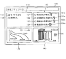
- FIG. 5 is a schematic diagram showing an example of the interface screen 100.
- the interface screen 100 shown in FIG. 5 shows an example of a screen displayed on the display unit 25 of the client device 20 after the client device 20 accesses the server device 10 and is authenticated as a legitimate user. ..
- the client device 20 communicates with the server device 10 and acquires data for the display screen from the server device 10, so that the interface screen 100 as shown in FIG. 5 can be displayed on the display unit 25.
- the interface screen 100 is a screen provided with various display fields and operation buttons arranged as components of the UI (User Interface), and is configured to accept operations by the user through the operation unit 24.
- UI User Interface
- the interface screen 100 shown as an example in FIG. 5 has a selection field 110 that accepts selection of cycle deterioration or deterioration over time, a selection field 120 that accepts selection of deterioration mechanism, a display field 130 that displays a calculation process during simulation, and battery information.
- the input field 140 for accepting the input of is provided.
- the selection field 110 includes a radio button 111 selected when giving a simulation execution instruction for cycle deterioration, and a radio button 112 selected when giving a simulation execution instruction for aging deterioration.
- the example of FIG. 5 shows a state in which the radio button 111 instructing the simulation of cycle deterioration is selected.
- the radio buttons 112 may be selected, or both the radio buttons 111 and 112 may be selected.
- the selection field 120 is selected when the deterioration mechanism of the power storage device is specified as an increase in electrical resistance, an isolation of active material particles, a decrease in conductivity of an electrolytic solution, and a decrease in charge carriers. It includes 124.
- the example of FIG. 5 shows a state in which the radio button 124, which specifies the reduction of charge carriers, is selected as the deterioration mechanism.
- any one of the radio buttons 121 to 123 may be selected, or two or more of the radio buttons 121 to 124 may be selected.
- edit buttons 121a to 124a are arranged corresponding to the radio buttons 121 to 124. When the edit buttons 121a to 124a are operated, the setting screen for accepting the setting change of various parameters is displayed for the corresponding deterioration mechanism.
- the calculation process during the simulation is displayed in the display field 130.
- the calculation process in the case of simulating cycle deterioration and aging deterioration for the decrease of charge carriers is shown by a graph.
- numerical data indicating the calculation process may be displayed.
- a download button 131 is arranged in the display field 130 so that the simulation result can be downloaded.
- the simulation result may be a graph or numerical data.
- the simulation results may be provided by a mathematical model.
- the mathematical model represents a model in which the deterioration process of the power storage device is mathematically described using algebraic equations, differential equations, and characteristic parameters, and is a model obtained by executing a simulation.
- Mathematical models include, for example, MATLAB (registered trademark), Amesim (registered trademark), TwinBiller (registered trademark), MATLAB & Simulink (registered trademark), Sampler (registered trademark), ANSYS (registered trademark), Abaqus (registered trademark), and Moderna. It is provided in the form of libraries, modules, etc. used in commercially available numerical analysis software such as (registered trademark), VHDL-AMS (registered trademark), C language, C ++, Java (registered trademark), or programming languages.
- an edit button 141 for editing information (battery information) of the power storage device is arranged in the input field 140.
- the client device 20 causes the display unit 25 to display a reception screen for receiving battery information.
- the client device 20 transmits the received battery information to the server device 10.
- the server device 10 registers the battery information received from the client device 20 in the battery table of the storage unit 12.
- the battery information is received through the input field 140.
- battery information is prepared in advance for each type and model number of the power storage device, and the battery information may be automatically set by accepting selection for the type and model number of the power storage device.
- the server device 10 When various conditions are set through the interface screen displayed on the display unit 25 of the client device 20, the server device 10 starts a simulation of deterioration of the power storage device.
- the server device 10 executes a simulation of deterioration using a physical model of a battery.
- the physical model represents a first-principles model, and is a model that expresses a phenomenon inside a power storage device by a mathematical formula or the like in accordance with an established natural phenomenon (physical law or chemical law).
- the physical model is also called a white box. Since it is considered difficult among those skilled in the art to express the deterioration mechanism of a power storage device by a physical model, deterioration simulation using the physical model has not been performed so far.
- the physical model used for the simulation of deterioration is a physical model represented by the Newman model.
- the Newman model assumes that homogeneous, single-diameter spheres are closely aligned at each of the positive and negative electrodes.
- the Newman model is described by the Nernst-Planck equation, the charge conservation equation, the diffusion equation, the Butler-Volmer equation, and the Nernst equation described below.
- the Nernst-Planck equation is an equation for solving ion electrophoresis and ion diffusion in an electrolyte or a porous electrode, and is expressed by the following equation.
- i l is the liquid phase current density (A / m 2 )
- ⁇ l and eff are the liquid phase effective conductivity (S / m)
- ⁇ l is the liquid phase potential (V)
- R is the gas constant (J / m).
- T is temperature (K)
- F is the Faraday constant (C / mol)
- f is the activity coefficient
- t + is a cation transport number
- Itot is the reaction current density per volume (A / m 3 ).
- the liquid-phase effective conductivity ⁇ l, eff is the apparent conductivity in the porous body, and is often expressed as a function of the liquid-phase bulk conductivity and the solid-phase volume ratio ⁇ s .
- the charge conservation formula is a formula that expresses electron conduction in active material particles and a current collector foil, and is expressed by the following formula.
- i s is the solid phase current density (A / m 2)
- ⁇ s is the solid phase potential (v)
- sigma s is the solid phase conductivity (S / m)
- i tot the reaction current density per volume A / m 3 ).
- the diffusion equation is an equation that expresses the diffusion of the active material in the active material particles, and is expressed by the following equation.
- c s is the charge carrier concentration in the solid phase (mol / m 3 )
- t is the time (s)
- D s is the diffusion coefficient in the solid phase (m 2 / s).
- the Butler-Volmer equation is an equation that expresses the activation overvoltage in the charge transfer reaction that occurs at the interface between the solid phase and the liquid phase
- the Nernst equation is the definition equation of the open circuit potential, which are expressed by the following equations.
- i loc is the reaction current density (A / m 2 )
- io is the exchange current density (A / m 2 )
- ⁇ a and ⁇ c are the transition coefficients of the oxidation reaction and the reduction reaction
- ⁇ is the activation overvoltage.
- V E eq is the equilibrium potential (V)
- E 0 is the standard equilibrium potential (V)
- z is the valence
- a Ox is the oxidizing agent concentration (mol / m 3 )
- a Red is the reducing agent concentration (mol / m /).
- m 3 As the Butler-Volmer equation and the Nernst equation, alternative equations modified based on experimental values are often used.
- the exchange current density may be made a function of the charge carrier concentration or the ion concentration, or the SOC and the measured data of the open circuit potential may be used as the open circuit potential.
- the open circuit potential In particular, in a lithium ion secondary battery, measured data of SOC and open circuit potential are often used, so a description will be added later.
- Each parameter in the above-mentioned equations 1 to 4 may be a function of other physical values.
- Equation 5 shows the relational expression between the charge carrier concentration in the solid phase and the charge carrier flux involved in the charge transfer reaction on the surface of the active material particles.
- r 0 represents the radius (m) of the active material particles
- J s is the flux of the charge carrier (mol / m 2 s).
- J s is the amount of charge carriers per unit area and unit time that is annihilated by the charge transfer reaction.
- Equation 6 is an equation expressing the relationship between the flux J s of the charge carrier and the reaction current density i loc .
- Equation 7 is an equation expressing the relationship between the reaction current density i loc and the reaction current density i tot per volume.
- S v represents the surface area per unit volume, that is, the specific surface area (m 2 / m 3 ).
- S v may be expressed as a function of the radius r 0 of the active material particle.
- FIG. 6 is a graph showing the relationship between the charge carrier concentration in the solid phase and the open circuit potential (OCP) in a typical positive electrode material.
- the horizontal axis of the graph is the dimensionless charge carriers is defined by the number 8 concentration theta, it is a function of charge carrier concentration c s.
- the vertical axis of the graph is the open circuit potential (OCP).
- the open circuit potential OCP of the positive electrode is expressed as a function of the dimensionless charge carrier concentration ⁇ in the positive electrode.
- the open circuit potential OCP of the negative electrode is expressed as a function of the nondimensionalized charge carrier concentration ⁇ in the negative electrode.
- the control unit 11 may use different open-circuit potential OCP values for discharging and charging.
- OCP open circuit potential
- FIG. 7 is a graph showing the relationship between the non-dimensionalized charge carrier concentration ⁇ of the electrode material having a high energy density and the open circuit potential OCP.
- the horizontal axis of the graph is the non-dimensionalized charge carrier concentration ⁇
- the vertical axis is the open circuit potential OCP.
- the value of the open circuit potential OCP differs between charging and discharging.
- Such properties are called OCP hysteresis or OCP history phenomena and are often found in electrode materials with high energy densities.
- the control unit 11 calculates such an electrode material, a precise simulation can be realized by using different open circuit potential OCP values between the time of discharge and the time of charge.
- the Newman model is shown as an example of the physical model of the lithium ion battery.
- a single particle model may be used in which the electrodes are represented by a single active particle.
- the non-patent document "Single-Particle Model for a Lithium-Ion Cell: Thermal Behavior, Meng Guo, Godfrey Sikha, and Ralph E. White, Journal of The Electrochemical Society, 158 (2) 122- The model disclosed in "132 (2011)" can be referred to.
- a model other than the physical model, such as an equivalent circuit model or a polynomial model, may be used instead as long as it expresses the charge / discharge characteristics.
- system identification that estimates the model from the measured input / output data may be used.
- the system identification may be black box modeling that estimates the model only from the input / output data, and when a part of the system structure is known, the known system structure is reflected and the model is estimated based on the input / output data. Gray box modeling may be performed.
- the polynomial model for example, the non-patent document “Modeling the Dependence of the Discharge Behavior of a Lithium-Ion Battery on the Environmental Temperature, Ui Seong Kim, a Jaesin Yi, a Chee Burm Shin, Tae The model disclosed in "Journal of The Electrochemical Society, 158 (5) 611-618 (2011)” can be referred to.
- the deterioration mechanism of the power storage device As the first deterioration mechanism, an increase in electrical resistance in each element constituting the power storage device will be described.
- the deterioration mechanism due to an increase in electrical resistance is a phenomenon in which the internal resistance of a battery increases due to an increase in the resistivity of an electrolytic solution or an electron conductive member, and the capacity of the battery decreases.
- the factors that increase the electrical resistance are (positive electrode, negative electrode) ⁇ (peeling between the current collector foil and the electrode, disconnection of the conductive path of the conductive auxiliary agent, formation of a resistor film).
- FIG. 8 is an explanatory diagram for explaining the peeling between the current collector foil and the electrode.
- the current collector foil and the electrode positive electrode or negative electrode
- the electrical resistance between the current collector foil and the electrode is relatively small.
- the current collecting foil and the electrode do not have a good bondability, cracks are formed between the particles (active material particles constituting the electrode) due to the expansion and contraction of the particles (active material particles constituting the electrode), the adhesion is lowered, and the particles are separated. ..
- the path through which the current flows decreases and the electrical resistance increases.
- FIG. 9 is an explanatory diagram for explaining the disconnection of the conduction path of the conductive auxiliary agent.
- the conductivity is maintained by adding a small amount of a conductive conductive auxiliary agent such as acetylene black.
- the conductive auxiliary agent itself is cut due to the expansion and contraction of the particles (active material particles constituting the electrode) due to charging and discharging, and the contact between the conductive auxiliary agent and other conductive auxiliary agents, active material particles, etc. is maintained. It may disappear. Alternatively, the conductive auxiliary agent may disappear due to a chemical reaction. As a result, the path through which the current flows decreases and the electrical resistance increases.
- FIG. 10 is an explanatory diagram illustrating the formation of the resistor coating.
- a film of a resistor is formed on the surface of the active material particles as the battery is charged and discharged.
- a film composed of a compound composed of an organic substance and lithium ions in the electrolytic solution is formed.
- Such a coating is inferior in conductivity and therefore has increased electrical resistance.
- the control unit 11 of the server device 10 calculates, for example, the speed at which the electrical resistance increases, that is, the speed at which the electrical conductivity decreases, according to the following equation (9) or (10).
- r cycle and res represent the speed (S / m / number of cycles) at which the electric conductivity decreases depending on the number of cycles.
- r cycle, res ⁇ 0. k 0, res is the reaction rate constant, for example a function of the number of cycles.
- E a0, res represents the activation energy (J / mol) of cycle deterioration, and is a coefficient representing the influence of temperature.
- i is the current density (A / m 2 ), and
- the magnitude of the current density i is a coefficient related to the expansion / contraction rate of the electrode and representing a strain rate-dependent fracture phenomenon such as creep.
- ⁇ res is a constant.
- rt and res represent the speed at which the electric conductivity decreases with the elapsed time (S / m / s).
- rt, res ⁇ 0.
- k 1 and res are reaction rate constants, for example a function of time.
- k 1, res may be defined by any function based on experimental data.
- E a1 and res represent the activation energy (J / mol) of deterioration over time, and are coefficients representing the influence of temperature.
- ⁇ t is the elapsed time (s).
- the values of k 1, res and E a 1, res may be input by the user or may be preset in the server device 10.
- ⁇ s (N + 1) is expressed by the equation of number 11 which is the sum of ⁇ s (N), the cycle deterioration rate, and the aging deterioration rate of one cycle.
- r cycle, res ⁇ 0 and rt , res ⁇ 0 are typically ⁇ s (N + 1) ⁇ s (N), and the conductivity decreases with increasing number of cycles and the passage of time. ..
- the configuration in which the speed at which the electric conductivity decreases is calculated by the equations of the equations 9 and 10, but the arithmetic equation is merely an example and can be freely modified based on the experimental results and literature data. You may.
- the control unit 11 may calculate the rate at which the electrical resistance increases using the number 12 as a function of the upper and lower limits of the SOC.
- the upper limit and the lower limit of the SOC represent the upper limit and the lower limit in the usage range of the battery.
- the control unit 11 can calculate the speed at which the electrical resistance increases depending on the number of cycles by the number 12 multiplied by a function having the upper limit value SOC max and the lower limit value SOC min of the SOC as arguments.
- the upper limit value SOC max and the lower limit value SOC min values may be input by the user or may be preset in the server device 10. In many cases, it is known that the higher the value of (SOC max- SOC min ), the faster the rate of increase in electrical resistance. Therefore, there is a function in which the reaction speed increases as (SOC max- SOC min ) increases. It is preferable to be used.
- k 0, res , E a0, res , ⁇ res , k 1, res , E a1, res , SOC max , and SOC min were used in the velocity equations that determine the increase in electrical resistance.
- different values may be used for the positive electrode and the negative electrode with respect to peeling between the current collector foil and the electrode, breaking the conduction path of the conductive auxiliary agent, and forming a resistor film. Alternatively, some or all of these values may be the same, if desired. These values may be different in the charging process and the discharging process.
- the deterioration mechanism due to the isolation of the active material particles is that the active material particles crack due to repeated expansion and contraction due to charging and discharging, the area where the charge carrier cannot be removed and inserted gradually increases, and the charge carrier of the active material particles is stored and released. This is a phenomenon in which the number of places that can be performed decreases and the amount of electricity that can be stored, that is, the battery capacity decreases. Occlusion is a phenomenon in which charge carriers are retained in a solid phase, that is, in active material particles. Release is a phenomenon in which charge carriers are discharged out of active material particles.
- the control unit 11 of the server device 10 calculates the speed at which the isolation of the active material particles progresses by the formula of the equation 13 or 14.
- r cycle and iso represent the rate (1 / number of cycles) at which the isolation of the active material particles progresses depending on the number of cycles.
- k 0, iso is the reaction rate constant, for example a function of the number of cycles.
- E a0, iso represents the activation energy (J / mol) of cycle deterioration, and is a coefficient representing the influence of temperature.
- i is the current density (A / m 2 ).
- the magnitude of the current density i is a coefficient related to the expansion / contraction rate of the electrode and representing a strain rate-dependent rupture phenomenon such as creep or crack growth.
- ⁇ iso is a constant.
- the values of k 0, iso , E a0, iso , and ⁇ iso may be input by the user or may be preset in the server device 10.
- rt and iso represent the rate at which the isolation of the active material particles progresses with the elapsed time (1 / s).
- rt, iso ⁇ 0.
- k 1 and iso are reaction rate constants, for example a function of time.
- k 1, iso may be defined by any function based on experimental data.
- E a1 and iso represent the activation energy (J / mol) of deterioration over time, and are coefficients representing the influence of temperature.
- ⁇ t is the elapsed time (s). When the stress inside the battery is low, isolation rarely progresses only with time, but it cannot be ignored when it is in a high stress state due to strong external restraint.
- the values of k 1, iso and E a 1, iso may be input by the user or may be preset in the server device 10.
- ⁇ s (N + 1) is the number 15 obtained by adding the cycle deterioration rate and the aging deterioration rate of one cycle to ⁇ s (N). It is expressed by the formula of.
- the reason why the storage device deteriorates when the solid-phase volume ratio ⁇ s of the active material particles decreases that is, the number of places where the charge carrier can be occluded in the storage device decreases, and the amount of electricity that can be stored, that is, the electric capacity decreases. ..
- the decrease in electrical capacity will be described using the minimum and maximum concentrations of c smin and c smax of the occluded charge carriers.
- the maximum concentration is at the end of discharge, and the minimum concentration is at full charge.
- the volume required to calculate the concentration of these charge carriers is the volume of the phase in which the occluded charge carriers can exist.
- the apparent volume of the electrode for example, coating area x coating thickness
- the solid-phase volume ratio of the active material particles in the electrode at the time of manufacture is ⁇ s0
- the volume of the phases that can is V app ⁇ s0.
- the battery capacity at the time of manufacture is Q 0 (C or Ah)
- the configuration for calculating the rate at which the isolation of the active material particles progresses as a function of the number of cycles or the elapsed time has been described.
- the control unit 11 uses the same equation as the equation 12 factorized by the function of the upper and lower limits of the SOC when the energization direction is switched, and the isolation of the active material particles proceeds. You may calculate the speed to do.
- the upper limit value SOC max and the lower limit value SOC min values may be input by the user or may be preset in the server device 10. In many cases, it is known that the larger the value of (SOC max- SOC min ), the faster the isolation progresses. Therefore, the function that the reaction speed increases as (SOC max- SOC min ) increases. It is preferable to be used.
- the total amount of electricity may be used instead of the number of cycles.
- the deterioration mechanism due to the decrease in conductivity in the electrolytic solution is the decrease in conductivity due to the disappearance of charge carriers, the decrease in conductivity due to the generation of minute bubbles in the electrode, the change in the molecular structure of solvation, the clogging of the separator, etc. This is a phenomenon in which the resistivity of the electrolytic solution increases, the internal resistance of the battery increases, and the capacity decreases. Charge carrier loss occurs primarily when a resistor coating is formed on the surface of the active material particles.
- FIG. 11 is a graph showing the relationship between the lithium ion concentration in the electrolytic solution and the ionic conductivity.
- the horizontal axis of the graph shown in FIG. 11 shows the lithium ion concentration in the electrolytic solution, and the vertical axis shows the ion conductivity.
- the relationship between the lithium ion concentration in the electrolytic solution and the ionic conductivity is often as shown in FIG.
- the control unit 11 of the server device 10 can calculate the rate of decrease in conductivity by the same function as in equations 5 and 6.
- the control unit 11 may calculate the rate of decrease in conductivity using the same equation as in Equation 8 factorized by the functions of the upper and lower limits of SOC.
- the conductivity of the ions may be changed.
- the reason why the lithium ion concentration of the electrolytic solution decreases is that the electrolyte salt is precipitated as an insoluble matter due to the product of the oxidation reaction of the electrolytic solution at the positive electrode in a very small amount. As a result, a reaction that traps more lithium ions than the number of electrons consumed in the reduction decomposition of the electrolytic solution at the negative electrode has occurred. As this reaction proceeds, the lithium ion concentration in the electrolytic solution gradually decreases, leading to a decrease in conductivity.
- the deterioration mechanism due to the decrease in charge carriers is a phenomenon in which ions in the electrolytic solution disappear due to a side reaction on the surface of the electrode during charging.
- a lithium ion battery when the lithium ion in the electrolyte solution enters the graphite (i.e. during charging), the main reaction - in addition to (Li + + e + 6C ⁇ LiC 6), and the reaction LiC 6 and an organic substance A side reaction occurs that adheres to the surface of the electrode active material particles as a resistor film.
- a main reaction is reversible reaction, when a voltage is applied in the reverse, Li ⁇ Li + + e - of the reaction takes place, side reactions are irreversible. That is, the lithium ion once formed as a resistor coating cannot participate in charging / discharging thereafter, and the capacity decreases.
- the fourth deterioration mechanism is caused by a decrease in the lithium ion concentration of the electrolytic solution, and does not mean that the electrode material is deteriorated. That is, the fourth deterioration mechanism has room for reuse after dismantling and cleaning.
- the fourth degradation mechanism is known to be accelerated by both time and cycle in the case of lithium-ion batteries.
- P is a substance that is the source of by-products.
- x: (1-x) is the stoichiometric ratio of the main reaction: the side reaction, but it is usually (1-x) / x ⁇ 1, and the stoichiometric coefficient of the side reaction is very small.
- Lithium ions which are obtained by multiplying the stoichiometric coefficient of the side reaction by the current density and the surface area of the electrode and dividing by the Faraday constant, disappear from the electrolytic solution.
- the amount of Li + disappeared in the liquid phase is J Li + (mol / m 2 s)
- x may be a function of the upper limit value SOC max, the lower limit value SOC min , the temperature T, and the current density i as appropriate. For example, it may be a function as described in Equation 20.
- h is an arbitrary function defined to fit the experimental data. Note that 0.0 ⁇ x ⁇ 1.0.
- the decrease in charge carriers involved in charging and discharging in the fourth deterioration mechanism is related to the formation of a resistor coating in the first deterioration mechanism and the decrease in conductivity in the electrolytic solution in the third deterioration mechanism. That is, the cause is that the lithium ions in the electrolytic solution are not used due to the irreversible reaction and are deposited on the electrode surface. In the simulation of the present application, it is possible to correlate and calculate these phenomena, which have been treated separately in the past.
- Equation 21 M is the molecular weight (kg / mol) of the coating substance.
- Equation 22 represents the total amount (mol) of lithium ions lost from the electrolytic solution due to the formation of a film over the surface area S (m 2 ) of the electrode active material particles up to time t (s).
- Equation 23 The ohm overvoltage generated by the resistor coating is expressed as Equation 23.
- r film is the resistivity ( ⁇ m 2 ) of the resistor coating.
- FIG. 12 is a flowchart illustrating a procedure of processing executed by the server device 10 and the client device 20.
- the control unit 21 of the client device 20 receives the data for the display screen transmitted from the server device 10 after the user authentication, and displays the interface screen 100 on the display unit 25 (step S101).
- the control unit 21 accepts the simulation conditions through the interface screen 100 displayed on the display unit 25 (step S102).
- the interface screen 100 accepts, for example, selection of cycle deterioration or deterioration over time, selection of deterioration mechanism, and input of battery information.
- the control unit 21 transmits the simulation conditions received through the interface screen 100 to the server device 10 through the communication unit 23 (step S103).
- the server device 10 receives the simulation conditions transmitted from the client device 20 in the communication unit 13 (step S104).
- the control unit 11 of the server device 10 executes the simulation based on the simulation conditions received through the communication unit 13 (step S105). At this time, the control unit 11 selects a simulation program corresponding to the simulation conditions and applies the simulation conditions to the selected simulation program to simulate the deterioration of the power storage device.
- the control unit 11 may store the simulation condition received in step S104 in the storage unit 12 in association with the user ID input at the time of user authentication.
- the control unit 11 transmits the calculation result to the client device 20 through the communication unit 13 (step S106).
- step S106 each time a value to be calculated in a certain time step or a certain cycle (electrical resistance for each component, volume ratio of isolated region, diffusion coefficient or ionic conductivity of electrolytic solution, expansion rate of battery, etc.) is obtained. , The calculation result may be transmitted to the client device 20 at any time.
- the client device 20 receives the calculation result transmitted from the server device 10 in the communication unit 23 (step S107).
- the control unit 21 of the client device 20 displays the received calculation result in the display field 130 of the interface screen 100 as the calculation process during the simulation (step S108).
- the user can grasp whether or not the simulation by the server device 10 is completed by referring to the calculation process displayed in the display field 130.
- control unit 21 transmits a download request for the simulation result to the server device 10 through the communication unit 23 (step S109).
- the server device 10 When the server device 10 receives the download request from the client device 20 (step S110), the server device 10 transmits the simulation result to the client device 20 (step S111).
- the simulation result transmitted by the server device 10 in step S111 was compared with the value of the electric resistance for each component, the volume ratio of the isolated region, the diffusion coefficient or ionic conductivity of the electrolytic solution, the reduced amount of charge carriers, and the initial state. It is data showing how the expansion rate of the battery changes with the elapsed time and the number of cycles.
- the simulation result may be numerical data in three columns of elapsed time, number of cycles, and physical value. Alternatively, it may be a graph, contour diagram or moving image generated from numerical data.
- the file format to be downloaded may be selected by the user depending on the numerical analysis software or programming language used by the user.
- the client device 20 receives the simulation result transmitted from the server device 10 in the communication unit 23 (step S112).
- the control unit 21 of the client device 20 causes the display unit 25 to display the received simulation result (step S113). Knowing the value of the electrical resistance of each component and the diffusion coefficient or ionic conductivity of the electrolytic solution, the calorific value at the time of energization can be calculated, so that the client can perform, for example, a temperature simulation. Therefore, cooling design and heat management design can be performed. Knowing the volume ratio of the isolated region and the reduced amount of charge carriers, the deterioration of the electrode material can be known, so that the client can predict, for example, the life cycle and the reuse rate. Knowing the expansion coefficient of the battery as compared to the initial state enables the client to design the strength of, for example, a module case or a battery can housing.
- Expansion of the battery due to deterioration includes expansion due to gas generation inside the battery, volume expansion due to cracking of the electrode, and expansion / contraction of the electrode due to charging / discharging.
- expansion due to gas generation and volume expansion due to cracking of the electrode are irreversible expansion and contraction that become larger than the original volume by one charge and discharge.
- the expansion and contraction of the electrode accompanying charge and discharge is a reversible expansion and contraction that returns to the original volume after performing one charge and discharge.
- the formula expressing the expansion can be, for example, several 24 to several 26.
- Equation 24 is an equation expressing the expansion due to gas generation as a function of the temperature T. That is, since the vapor pressure rises as the temperature rises, evaporation of the electrolytic solution and desorption of gas from the electrodes are likely to occur.
- alpha crack coefficient of linear expansion of the original volume by the electrode cracking epsilon s0 effective active material particle volume fraction during manufacture of the electrode
- epsilon s is the effective active material particle volume ratio of the electrode at any time.
- the effective active material particle volume ratio is the volume ratio of the non-isolated portion of the volume of the solid portion of the electrode.
- the number 26 represents the total linear expansion coefficient, and is a function with the expansion due to gas generation and the expansion due to electrode cracking as arguments.
- the expansion formula can be changed as appropriate depending on the battery type and battery material, and is not limited to the above-mentioned number 24 to number 26.
- FIG. 13 is a graph showing the change over time in the expansion coefficient.
- the horizontal axis of the graph shown in FIG. 13 represents time (or the number of cycles), and the vertical axis represents the coefficient of expansion.
- the expansion rate of the battery is the sum of the component that monotonically increases while gradually decreasing and the component that expands and contracts with charging and discharging.
- the former is an irreversible (plastic) expansion and the latter is a reversible (elastic) expansion. Irreversible expansion is given to increase as a function of time and number of cycles, and the relationship between expansion rate and elapsed time and number of cycles should be obtained experimentally.
- the expansion coefficient by a geometric progression with the elapsed time and the number of cycles as arguments. For example, assuming that the increase in the expansion rate in one cycle is r (typically 0 ⁇ r ⁇ 1), the expansion rate after the N cycle is represented by the equation 27 with ⁇ 0 as a constant.
- the deterioration simulation model may include a stress strain model and a fatigue model. It is known that most of the electrode materials change in volume with charge and discharge. In particular, in the electrode material of a lithium ion battery, the volume change due to the removal and insertion of lithium in the charge carrier is remarkable. Normally, since the battery is restrained by a resin material, a metal material, high-tensile steel, or the like, a large internal stress is generated when the electrode material expands, and minute cracks (cracks) may occur in the active material particles. This crack causes the isolation of the active material particles described above. Therefore, a design that does not increase the stress in the active material particles is desired.
- the part that calculates the electrochemical of this model is connected to the electrical network of the numerical analysis software, and the part that calculates the stress strain is connected to the commercially available numerical analysis software (such as structural analysis simulation software of the finite element method). May be good. This makes it possible to calculate the deterioration and stress strain of the battery while simultaneously coupling them.
- the deterioration simulation model may include a heat transfer model. Batteries with advanced deterioration, especially batteries with increased electrical resistance and decreased conductivity in the electrolytic solution, tend to generate a large amount of heat. In general, the higher the temperature, the faster the deterioration progresses, and temperature control is also an important factor in suppressing the deterioration of the battery.
- the part that calculates the electrochemical of this model may be connected to the electric network of the numerical analysis software, and the part that calculates the heat may be connected to the thermal network calculation part of the commercially available numerical analysis software. This makes it possible to calculate the deterioration and heat generation of the battery while simultaneously coupling them.
- the deterioration of the power storage device can be simulated in consideration of the deterioration mechanism, and the simulation result can be provided to the user. If necessary, a mathematical model obtained as a result of simulating the deterioration of the power storage device can be provided to the user. Therefore, in the client device 20, the power storage device is used under desired conditions by using the mathematical model downloaded from the server device 10. Alternatively, the simulation result of the system including the power storage device can be acquired. The client device 20 may download the simulation program used for calculating the simulation result from the server device 10.
- the simulation program downloaded to the client device 20 When using the simulation program downloaded to the client device 20, it may be a requirement to communicate with the server device 10 and receive user authentication. At that time, the simulation conditions input to the client device 20 may be transmitted to the server device 10.
- a wound lithium ion battery in which the electrolyte is a liquid is taken as an example.
- the simulation method of the present application is not limited to battery types such as all-solid-state lithium-ion batteries, bipolar lithium-ion batteries (electrodes connected in series electrically), zinc air batteries, sodium ion batteries, and lead batteries. Can be applied.
- a mode in which a simulation is performed by communication between the server device 10 and the client device 20 is illustrated.
- the server administrator may provide the simulation program to the client user by means of a storage medium such as a DVD-ROM, and the simulation may be performed locally on the client terminal.
- a download format via communication may be used. That is, when the control unit 21 of the client device 20 executes the simulation program, the client device 20 receives the selection information regarding the deterioration mechanism of the power storage device, and executes the deterioration simulation of the power storage device using the selected deterioration mechanism. , It is configured to function as a development support device of the present application that outputs simulation results.
Abstract
A development support device that comprises: a reception unit that, after user authentication at a terminal device, receives selection information about a degradation mechanism for a power storage device from the terminal device; a simulation execution unit that, on the basis of the received selection information, simulates degradation of the power storage device using the selected degradation mechanism; and a transmission unit that sends the terminal device simulation results from the simulation execution unit or a simulation program that is to be executed when degradation of the power storage device is simulated.
Description
本発明は、コンピュータに実装される開発支援装置、開発支援方法、及びコンピュータプログラムに関する。
The present invention relates to a development support device, a development support method, and a computer program mounted on a computer.
近年、自動車業界を始めとした各業界で、MBD(モデルベース開発)が盛んに導入されており、シミュレーションに基づいた製品開発が浸透している(例えば、特許文献1を参照)。
In recent years, MBD (model-based development) has been actively introduced in various industries including the automobile industry, and product development based on simulation has become widespread (see, for example, Patent Document 1).
開発要素の1つである電池に関して劣化予測を行えることは、電池筐体の強度設計、ライフサイクル設計、冷却装置設計および維持管理など、電池を購入して組み立てる自動車メーカ、蓄電システムメーカなどの企業にとって重要である。しかしながら、電池の劣化挙動を専門家以外が把握することは困難である。
One of the development factors that can predict deterioration of batteries is companies such as automobile manufacturers and power storage system manufacturers that purchase and assemble batteries, such as battery housing strength design, life cycle design, cooling device design and maintenance management. Is important for. However, it is difficult for anyone other than an expert to grasp the deterioration behavior of the battery.
電池の電極に用いられる元素の産出量は少なく、今後はリユースが進むと考えられている。しかしながら、劣化状態によってはリユースが困難である場合もあり、回収率を把握し、適切なリサイクルを行うためには、劣化メカニズムに基づいた劣化挙動の把握が重要である。
The amount of elements used for battery electrodes is small, and it is thought that reuse will progress in the future. However, reuse may be difficult depending on the deterioration state, and it is important to grasp the deterioration behavior based on the deterioration mechanism in order to grasp the recovery rate and perform appropriate recycling.
本発明は、劣化メカニズムを考慮した蓄電デバイスの劣化シミュレーションの結果またはシミュレーションプログラムをネットワーク経由でユーザに提供できる開発支援装置、開発支援方法、及びコンピュータプログラムを提供することを目的とする。
An object of the present invention is to provide a development support device, a development support method, and a computer program capable of providing a deterioration simulation result or a simulation program of a power storage device in consideration of a deterioration mechanism to a user via a network.
本発明の一局面に係る開発支援装置は、端末装置のユーザ認証後に、前記端末装置から、蓄電デバイスの劣化メカニズムに関する選択情報を受信する受信部と、受信した選択情報に基づき、選択された劣化メカニズムを用いて前記蓄電デバイスの劣化をシミュレートするシミュレーション実行部と、該シミュレーション実行部によるシミュレーション結果、または、前記蓄電デバイスの劣化をシミュレートする際に実行されるシミュレーションプログラムを前記端末装置へ送信する送信部とを備える。
The development support device according to one aspect of the present invention is a receiving unit that receives selection information regarding the deterioration mechanism of the power storage device from the terminal device after user authentication of the terminal device, and deterioration selected based on the received selection information. A simulation execution unit that simulates the deterioration of the power storage device using a mechanism, a simulation result by the simulation execution unit, or a simulation program that is executed when simulating the deterioration of the power storage device is transmitted to the terminal device. A transmitter is provided.
本発明の他の局面に係る開発支援方法は、端末装置と通信可能に接続される開発支援装置を用いて、蓄電デバイスの劣化メカニズムに関する複数の選択肢を提示し、選択された劣化メカニズムに関する選択情報を前記端末装置から受信し、受信した選択情報に基づき、選択された劣化メカニズムを用いて前記蓄電デバイスの劣化をシミュレートし、シミュレーション結果、または、前記蓄電デバイスの劣化をシミュレートする際に実行されるシミュレーションプログラムを前記端末装置へ送信する。
The development support method according to another aspect of the present invention presents a plurality of options regarding the deterioration mechanism of the power storage device by using the development support device communicably connected to the terminal device, and presents selection information regarding the selected deterioration mechanism. Is received from the terminal device, and based on the received selection information, the deterioration of the power storage device is simulated using the selected deterioration mechanism, and the simulation result or the deterioration of the power storage device is simulated. The simulation program to be generated is transmitted to the terminal device.
本発明の他の局面に係るコンピュータプログラムは、コンピュータに、蓄電デバイスの劣化メカニズムに関する複数の選択肢を提示し、提示した選択肢に基づき、前記蓄電デバイスの劣化メカニズムに関する選択を受付け、選択された劣化メカニズムを用いて、前記蓄電デバイスの劣化をシミュレートし、シミュレーション結果、または、前記蓄電デバイスの劣化をシミュレートする際に実行されるシミュレーションプログラムを出力する処理を実行させる。
The computer program according to another aspect of the present invention presents the computer with a plurality of options regarding the deterioration mechanism of the power storage device, accepts the selection regarding the deterioration mechanism of the power storage device based on the presented options, and selects the deterioration mechanism. Is used to simulate the deterioration of the power storage device, and the process of outputting the simulation result or the simulation program executed when simulating the deterioration of the power storage device is executed.
上記構成によれば、劣化メカニズムを考慮した蓄電デバイスの劣化シミュレーションの結果をネットワーク経由でユーザに提供できる。
According to the above configuration, the result of the deterioration simulation of the power storage device considering the deterioration mechanism can be provided to the user via the network.
開発支援装置は、端末装置のユーザ認証後に、前記端末装置から、蓄電デバイスの劣化メカニズムに関する選択情報を受信する受信部と、受信した選択情報に基づき、選択された劣化メカニズムを用いて前記蓄電デバイスの劣化をシミュレートするシミュレーション実行部と、該シミュレーション実行部によるシミュレーション結果、または、前記蓄電デバイスの劣化をシミュレートする際に実行されるシミュレーションプログラムを前記端末装置へ送信する送信部とを備える。
したがって、ユーザが蓄電デバイスの劣化メカニズムに精通していない場合であっても、開発支援装置は、劣化メカニズムに関する選択情報を受付けるだけで、蓄電デバイスの劣化シミュレーションの結果をユーザに提供できる。ユーザは提供される劣化シミュレーションの結果に基づき、製品のライフサイクル予測、取り替え時期予測、リユース目的の回収率予測、発熱量等を把握できる。開発支援装置は、蓄電デバイスの劣化をシミュレートする際に実行されるシミュレーションプログラムを提供してもよい。ユーザは端末装置においてシミュレーションプログラムを実行することによって、蓄電デバイスの劣化シミュレーションの結果を取得できる。 The development support device is a receiving unit that receives selection information about the deterioration mechanism of the power storage device from the terminal device after user authentication of the terminal device, and the power storage device using the deterioration mechanism selected based on the received selection information. It includes a simulation execution unit that simulates the deterioration of the storage device, and a transmission unit that transmits a simulation result by the simulation execution unit or a simulation program executed when simulating the deterioration of the power storage device to the terminal device.
Therefore, even if the user is not familiar with the deterioration mechanism of the power storage device, the development support device can provide the user with the result of the deterioration simulation of the power storage device only by accepting the selection information regarding the deterioration mechanism. Based on the results of the deterioration simulation provided, the user can grasp the product life cycle prediction, replacement time prediction, recovery rate prediction for reuse purpose, heat generation amount, and the like. The development support device may provide a simulation program executed when simulating the deterioration of the power storage device. The user can acquire the result of the deterioration simulation of the power storage device by executing the simulation program in the terminal device.
前記シミュレーション実行部は、前記蓄電デバイスを表す物理モデルを用いて、シミュレーションを実行してもよい。この構成によれば、蓄電デバイスの物理モデルを用いてシミュレーションを実行するので、蓄電デバイス内部の物理現象を的確に反映させたシミュレーション結果を得ることができる。
The simulation execution unit may execute a simulation using a physical model representing the power storage device. According to this configuration, since the simulation is executed using the physical model of the power storage device, it is possible to obtain a simulation result that accurately reflects the physical phenomenon inside the power storage device.
前記劣化メカニズムは、前記蓄電デバイスを構成する各要素における電気抵抗の増加、活物質粒子の孤立化(孤立化の意味は後述する)、電解液における導電性の低下、及び充放電に関与する電荷担体の減少の少なくとも1つを含んでもよい。この構成によれば、各要素における電気抵抗の増加、活物質粒子の孤立化、電解液における導電性の低下、電荷担体の減少を劣化メカニズムとして、蓄電デバイスの劣化をシミュレートできる。本明細書中において、活物質粒子は、一次粒子が凝集した二次粒子や、一次粒子のみからなるものなどを指す。活物質は電子の授受を行う物質のことであり、リチウムイオン電池の代表的な活物質はリチウム金属複合酸化物や炭素材料である。本明細書中において、電荷担体とは、固相内又は液相内に存在する電荷のキャリアのことを指し、例えばリチウムイオン電池であればリチウムイオンLi+ のことである。
The deterioration mechanism includes an increase in electrical resistance in each element constituting the power storage device, isolation of active material particles (the meaning of isolation will be described later), a decrease in conductivity in an electrolytic solution, and charges involved in charging and discharging. It may include at least one reduction in carrier. According to this configuration, deterioration of the power storage device can be simulated by using an increase in electrical resistance in each element, isolation of active material particles, a decrease in conductivity in an electrolytic solution, and a decrease in charge carriers as deterioration mechanisms. In the present specification, the active material particles refer to secondary particles in which primary particles are aggregated, particles composed of only primary particles, and the like. An active material is a substance that transfers electrons, and a typical active material of a lithium ion battery is a lithium metal composite oxide or a carbon material. In the present specification, the charge carrier refers to a charge carrier existing in a solid phase or a liquid phase, for example, in the case of a lithium ion battery, it is lithium ion Li + .
前記電気抵抗の増加は、集電箔と多孔体電極との接着部における電気抵抗の増加、活物質粒子中の導電経路の減少に伴う電気抵抗の増加、または、粒子表面の抵抗体被膜の増加に伴う電気抵抗の増加を含んでもよい。この構成によれば、集電箔と多孔体電極との接着部における電気抵抗の増加、活物質粒子中の導電経路の減少に伴う電気抵抗の増加、または、粒子表面の抵抗体被膜の増加に伴う電気抵抗の増加を考慮して、蓄電デバイスの劣化をシミュレートできる。
The increase in electrical resistance is due to an increase in electrical resistance at the junction between the current collecting foil and the porous electrode, an increase in electrical resistance due to a decrease in the conductive path in the active material particles, or an increase in the resistor coating on the particle surface. It may include an increase in electrical resistance associated with it. According to this configuration, the electric resistance at the bonding portion between the current collecting foil and the porous electrode is increased, the electric resistance is increased due to the decrease of the conductive path in the active material particles, or the resistance coating on the particle surface is increased. Considering the accompanying increase in electrical resistance, deterioration of the power storage device can be simulated.
前記電気抵抗の増加、前記活物質粒子の孤立化、及び前記導電性の低下は、放電時のSOCの上限及び下限の関数により表されてもよい。この構成によれば、蓄電デバイスが搭載された機器の使用状況を考慮して、蓄電デバイスの劣化をシミュレートできる。SOCとはState Of Chargeの略称であり、満充電状態を100%、完全放電状態を0%として表す。
The increase in electrical resistance, the isolation of the active material particles, and the decrease in conductivity may be represented by a function of the upper and lower limits of SOC during discharge. According to this configuration, deterioration of the power storage device can be simulated in consideration of the usage status of the device equipped with the power storage device. SOC is an abbreviation for State Of Charge, and represents a fully charged state as 100% and a fully discharged state as 0%.
前記電気抵抗の増加、前記活物質粒子の孤立化、前記導電性の低下、及び前記電荷担体の減少は、経過時間、サイクル数、及び温度の少なくとも1つの関数により表されてもよい。この構成によれば、蓄電デバイスの劣化を経過時間、サイクル数、又は温度の関数として提示できる。本明細書中において、サイクル数とは充放電を行った回数を表す。
The increase in electrical resistance, the isolation of the active material particles, the decrease in conductivity, and the decrease in charge carriers may be represented by at least one function of elapsed time, number of cycles, and temperature. According to this configuration, the deterioration of the power storage device can be presented as a function of elapsed time, number of cycles, or temperature. In the present specification, the number of cycles represents the number of times of charging / discharging.
前記電荷担体の減少は、充電時における負極表面での電荷移動過程の量論係数により表されてもよい。この構成によれば、電荷担体の減少を、量論係数により表すことができる。
The decrease in the charge carrier may be represented by a stoichiometric coefficient of the charge transfer process on the surface of the negative electrode during charging. According to this configuration, the decrease in charge carriers can be represented by stoichiometric coefficients.
前記シミュレーション結果は、前記蓄電デバイスを構成する各要素における電気抵抗の値、活物質粒子の孤立化領域の体積割合、電解液の拡散係数又はイオン導電率、電荷担体量、及び蓄電デバイスの膨張率のうち、何れか1つの時間変化又はサイクル変化を含んでもよい。この構成によれば、電気抵抗の値、活物質粒子の孤立化領域の体積割合、電解液の拡散係数又はイオン導電率、電荷担体量、及び蓄電デバイスの膨張率を経過時間又はサイクル数の関数として提示できる。
The simulation results show the value of electrical resistance in each element constituting the power storage device, the volume ratio of the isolated region of the active material particles, the diffusion coefficient or ionic conductivity of the electrolytic solution, the amount of charge carriers, and the expansion rate of the power storage device. Of these, any one of them may include a time change or a cycle change. According to this configuration, the value of electrical resistance, the volume ratio of the isolated region of the active material particles, the diffusion coefficient or ionic conductivity of the electrolytic solution, the amount of charge carriers, and the expansion rate of the storage device are functions of the elapsed time or the number of cycles. Can be presented as.
開発支援装置は、蓄電デバイスの劣化メカニズムに関する選択情報を受付ける受付部と、受付けた選択情報に基づき、選択された劣化メカニズムを用いて前記蓄電デバイスの劣化をシミュレートするシミュレーション実行部と、該シミュレーション実行部によるシミュレーション結果、または、前記蓄電デバイスの劣化をシミュレートする際に実行されるシミュレーションプログラムを出力する出力部とを備える。この構成によれば、ユーザが蓄電デバイスの劣化メカニズムに精通していない場合であっても、開発支援装置は、劣化メカニズムに関する選択情報を受付けるだけで、蓄電デバイスの劣化シミュレーションの結果をユーザに提供できる。上記構成によれば、開発支援装置は、シミュレーションプログラムをユーザに提供できるので、ユーザは端末装置を用いてシミュレーションプログラムを実行することによって、蓄電デバイスの劣化シミュレーションの結果を取得できる。
The development support device includes a reception unit that receives selection information regarding the deterioration mechanism of the power storage device, a simulation execution unit that simulates the deterioration of the power storage device using the selected deterioration mechanism based on the received selection information, and the simulation. It includes an output unit that outputs a simulation result by the execution unit or a simulation program that is executed when simulating the deterioration of the power storage device. According to this configuration, even if the user is not familiar with the deterioration mechanism of the power storage device, the development support device simply accepts the selection information regarding the deterioration mechanism and provides the user with the result of the deterioration simulation of the power storage device. it can. According to the above configuration, since the development support device can provide the simulation program to the user, the user can acquire the result of the deterioration simulation of the power storage device by executing the simulation program using the terminal device.
開発支援方法は、端末装置と通信可能に接続される開発支援装置を用いて、蓄電デバイスの劣化メカニズムに関する複数の選択肢を提示し、選択された劣化メカニズムに関する選択情報を前記端末装置から受信し、受信した選択情報に基づき、選択された劣化メカニズムを用いて前記蓄電デバイスの劣化をシミュレートし、シミュレーション結果、または、前記蓄電デバイスの劣化をシミュレートする際に実行されるシミュレーションプログラムを前記端末装置へ送信する。この構成によれば、ユーザが蓄電デバイスの劣化メカニズムに精通していない場合であっても、開発支援装置は、劣化メカニズムに関する選択情報を受付けるだけで、蓄電デバイスの劣化シミュレーションの結果をユーザに提供できる。上記構成によれば、開発支援装置は、シミュレーションプログラムをユーザに提供できるので、ユーザは端末装置を用いてシミュレーションプログラムを実行することによって、蓄電デバイスの劣化シミュレーションの結果を取得できる。
The development support method presents a plurality of options regarding the deterioration mechanism of the power storage device by using the development support device communicably connected to the terminal device, receives selection information regarding the selected deterioration mechanism from the terminal device, and receives the selection information. Based on the received selection information, the terminal device simulates the deterioration of the power storage device by using the selected deterioration mechanism, and executes the simulation result or the simulation program executed when simulating the deterioration of the power storage device. Send to. According to this configuration, even if the user is not familiar with the deterioration mechanism of the power storage device, the development support device simply accepts the selection information regarding the deterioration mechanism and provides the user with the result of the deterioration simulation of the power storage device. it can. According to the above configuration, since the development support device can provide the simulation program to the user, the user can acquire the result of the deterioration simulation of the power storage device by executing the simulation program using the terminal device.
開発支援方法は、コンピュータを用いて、蓄電デバイスの劣化メカニズムに関する複数の選択肢を提示し、提示した選択肢に基づき、前記蓄電デバイスの劣化メカニズムに関する選択を受付け、選択された劣化メカニズムを用いて、前記蓄電デバイスの劣化をシミュレーションし、シミュレーション結果、または、前記蓄電デバイスの劣化をシミュレートする際に実行されるシミュレーションプログラムを出力する。この構成によれば、ユーザが蓄電デバイスの劣化メカニズムに精通していない場合であっても、開発支援装置は、劣化メカニズムに関する選択情報を受付けるだけで、蓄電デバイスの劣化シミュレーションの結果をユーザに提供できる。上記構成によれば、開発支援装置は、シミュレーションプログラムをユーザに提供できるので、ユーザは端末装置を用いてシミュレーションプログラムを実行することによって、蓄電デバイスの劣化シミュレーションの結果を取得できる。
The development support method presents a plurality of options regarding the deterioration mechanism of the power storage device using a computer, accepts the selection regarding the deterioration mechanism of the power storage device based on the presented options, and uses the selected deterioration mechanism to describe the above. The deterioration of the power storage device is simulated, and the simulation result or the simulation program executed when simulating the deterioration of the power storage device is output. According to this configuration, even if the user is not familiar with the deterioration mechanism of the power storage device, the development support device simply accepts the selection information regarding the deterioration mechanism and provides the user with the result of the deterioration simulation of the power storage device. it can. According to the above configuration, since the development support device can provide the simulation program to the user, the user can acquire the result of the deterioration simulation of the power storage device by executing the simulation program using the terminal device.
コンピュータプログラムは、コンピュータに、蓄電デバイスの劣化メカニズムに関する複数の選択肢を提示し、選択された劣化メカニズムに関する選択情報を端末装置から受信し、受信した選択情報に基づき、選択された劣化メカニズムを用いて前記蓄電デバイスの劣化をシミュレートし、シミュレーション結果、または、前記蓄電デバイスの劣化をシミュレートする際に実行されるシミュレーションプログラムを前記端末装置へ送信する処理を実行させる。この構成によれば、ユーザが蓄電デバイスの劣化メカニズムに精通していない場合であっても、開発支援装置は、劣化メカニズムに関する選択情報を受付けるだけで、蓄電デバイスの劣化シミュレーションの結果をユーザに提供できる。上記構成によれば、開発支援装置は、シミュレーションプログラムをユーザに提供できるので、ユーザは端末装置を用いてシミュレーションプログラムを実行することによって、蓄電デバイスの劣化シミュレーションの結果を取得できる。
The computer program presents the computer with multiple options for the degradation mechanism of the power storage device, receives selection information about the selected degradation mechanism from the terminal device, and uses the selected degradation mechanism based on the received selection information. The process of simulating the deterioration of the power storage device and transmitting the simulation result or the simulation program executed when simulating the deterioration of the power storage device to the terminal device is executed. According to this configuration, even if the user is not familiar with the deterioration mechanism of the power storage device, the development support device simply accepts the selection information regarding the deterioration mechanism and provides the user with the result of the deterioration simulation of the power storage device. it can. According to the above configuration, since the development support device can provide the simulation program to the user, the user can acquire the result of the deterioration simulation of the power storage device by executing the simulation program using the terminal device.
コンピュータプログラムは、コンピュータに、蓄電デバイスの劣化メカニズムに関する複数の選択肢を提示し、提示した選択肢に基づき、前記蓄電デバイスの劣化メカニズムに関する選択を受付け、選択された劣化メカニズムを用いて、前記蓄電デバイスの劣化をシミュレートし、シミュレーション結果、または、前記蓄電デバイスの劣化をシミュレートする際に実行されるシミュレーションプログラムを出力する処理を実行させる。この構成によれば、ユーザが蓄電デバイスの劣化メカニズムに精通していない場合であっても、開発支援装置は、劣化メカニズムに関する選択情報を受付けるだけで、蓄電デバイスの劣化シミュレーションの結果をユーザに提供できる。上記構成によれば、開発支援装置は、シミュレーションプログラムをユーザに提供できるので、ユーザは端末装置を用いてシミュレーションプログラムを実行することによって、蓄電デバイスの劣化シミュレーションの結果を取得できる。
The computer program presents the computer with a plurality of options regarding the deterioration mechanism of the power storage device, accepts the selection regarding the deterioration mechanism of the power storage device based on the presented options, and uses the selected deterioration mechanism to obtain the power storage device. Deterioration is simulated, and a process of outputting a simulation result or a simulation program executed when simulating deterioration of the power storage device is executed. According to this configuration, even if the user is not familiar with the deterioration mechanism of the power storage device, the development support device simply accepts the selection information regarding the deterioration mechanism and provides the user with the result of the deterioration simulation of the power storage device. it can. According to the above configuration, since the development support device can provide the simulation program to the user, the user can acquire the result of the deterioration simulation of the power storage device by executing the simulation program using the terminal device.
コンピュータプログラムは、コンピュータに、蓄電デバイスの劣化メカニズムに関する複数の選択肢を提示し、提示した選択肢に基づき、前記蓄電デバイスの劣化メカニズムに関する選択を受付け、選択された劣化メカニズムを用いて前記蓄電デバイスの劣化をサーバ装置にシミュレートさせるべく、前記劣化メカニズムの選択情報を前記サーバ装置へ送信する処理を実行させる。この構成によれば、劣化メカニズムに基づいて蓄電デバイスの劣化をシミュレートするサーバ装置に対して、劣化メカニズムの選択情報を送信するので、選択した劣化メカニズムに基づくシミュレーション結果が得られる。
The computer program presents the computer with a plurality of options regarding the deterioration mechanism of the power storage device, accepts the selection regarding the deterioration mechanism of the power storage device based on the presented options, and uses the selected deterioration mechanism to deteriorate the power storage device. Is executed by the server device to transmit the selection information of the deterioration mechanism to the server device. According to this configuration, the selection information of the deterioration mechanism is transmitted to the server device that simulates the deterioration of the power storage device based on the deterioration mechanism, so that the simulation result based on the selected deterioration mechanism can be obtained.
ユーザに提供されるシミュレーションプログラムは、劣化を計算する計算プログラムだけでなく、後述する電気化学モデルに基づく計算プログラムを含んでもよい。
The simulation program provided to the user may include not only a calculation program for calculating deterioration but also a calculation program based on an electrochemical model described later.
以下、本発明をその実施の形態を示す図面に基づいて具体的に説明する。
図1は実施の形態に係るシミュレーションシステムの全体構成を説明するブロック図である。実施の形態に係るシミュレーションシステムは、通信網Nを介して互いに通信可能に接続されるサーバ装置10とクライアント装置20とを備える。サーバ装置10は、クライアント装置20からの要求に応じて、蓄電デバイスの劣化をシミュレートし、シミュレーション結果をクライアント装置20へ提供する。ここで、蓄電デバイスの劣化とは、例えば蓄電デバイスを繰り返し使用していると充放電容量が低下するようになり、放電が長持ちしなくなる事象を表す。劣化は、時間が経過するだけで生じる経年劣化と、使用回数(充放電を行った回数)に応じて生じるサイクル劣化とに区別される。 Hereinafter, the present invention will be specifically described with reference to the drawings showing the embodiments thereof.
FIG. 1 is a block diagram illustrating an overall configuration of a simulation system according to an embodiment. The simulation system according to the embodiment includes aserver device 10 and a client device 20 that are communicably connected to each other via a communication network N. The server device 10 simulates the deterioration of the power storage device in response to the request from the client device 20, and provides the simulation result to the client device 20. Here, the deterioration of the power storage device represents, for example, an event in which the charge / discharge capacity decreases when the power storage device is used repeatedly, and the discharge does not last long. Deterioration is divided into aged deterioration that occurs only with the passage of time and cycle deterioration that occurs according to the number of times of use (the number of times of charging and discharging).
図1は実施の形態に係るシミュレーションシステムの全体構成を説明するブロック図である。実施の形態に係るシミュレーションシステムは、通信網Nを介して互いに通信可能に接続されるサーバ装置10とクライアント装置20とを備える。サーバ装置10は、クライアント装置20からの要求に応じて、蓄電デバイスの劣化をシミュレートし、シミュレーション結果をクライアント装置20へ提供する。ここで、蓄電デバイスの劣化とは、例えば蓄電デバイスを繰り返し使用していると充放電容量が低下するようになり、放電が長持ちしなくなる事象を表す。劣化は、時間が経過するだけで生じる経年劣化と、使用回数(充放電を行った回数)に応じて生じるサイクル劣化とに区別される。 Hereinafter, the present invention will be specifically described with reference to the drawings showing the embodiments thereof.
FIG. 1 is a block diagram illustrating an overall configuration of a simulation system according to an embodiment. The simulation system according to the embodiment includes a
実施の形態において、シミュレーション対象の蓄電デバイスは、電解質が液体の巻回式リチウムイオン電池である。代替的には、シミュレーション対象の蓄電デバイスは、ラミネートタイプのリチウムイオン電池、電解質がイオン液体のリチウムイオン電池、電解質がゲル状のリチウムイオン電池、全固体リチウムイオン電池、バイポーラ型リチウムイオン電池(電極が電気的直列に接続されたもの)、亜鉛空気電池、ナトリウムイオン電池、鉛電池などの任意の電池であってもよい。蓄電デバイスは、複数のセルを直列に接続したモジュール、複数のモジュールを直列に接続したバンク、複数のバンクを並列に接続したドメイン等を含んでもよい。以下の説明において、蓄電デバイスを単に電池とも称する。
In the embodiment, the power storage device to be simulated is a wound lithium-ion battery having a liquid electrolyte. Alternatively, the energy storage device to be simulated is a laminated type lithium ion battery, a lithium ion battery having an ion liquid electrolyte, a gel lithium ion battery having an electrolyte, an all-solid lithium ion battery, or a bipolar lithium ion battery (electrode). Is electrically connected in series), may be any battery such as a zinc air battery, a sodium ion battery, a lead battery, and the like. The power storage device may include a module in which a plurality of cells are connected in series, a bank in which a plurality of modules are connected in series, a domain in which a plurality of banks are connected in parallel, and the like. In the following description, the power storage device is also simply referred to as a battery.
クライアント装置20は、ユーザによって利用されるパーソナルコンピュータ、スマートフォン、タブレット端末などの端末装置である。クライアント装置20には、サーバ装置10にアクセスするためのソフトウェア(アプリケーションプログラム)がインストールされている。サーバ装置10は、クライアント装置20からのアクセスを受付けた際に例えばユーザID及びパスワードに基づくユーザ認証を行い、ユーザ認証に成功した場合、クライアント装置20に対して適宜のサービスを提供する。ユーザは、蓄電デバイスの製品設計を行うメーカの技術者であってもよく、蓄電デバイスが搭載された製品を使用するエンドユーザであってもよい。
The client device 20 is a terminal device such as a personal computer, a smartphone, or a tablet terminal used by a user. Software (application program) for accessing the server device 10 is installed in the client device 20. The server device 10 performs user authentication based on, for example, a user ID and password when receiving access from the client device 20, and if the user authentication is successful, provides an appropriate service to the client device 20. The user may be an engineer of a manufacturer who designs a product of a power storage device, or may be an end user who uses a product equipped with the power storage device.
実施の形態に係るサーバ装置10は、ユーザ認証の後、クライアント装置20のユーザによる各種入力を受付けるためのインタフェース画面100(図5を参照)をクライアント装置20へ送信する。インタフェース画面100は、蓄電デバイスの劣化をシミュレートするために必要な条件を受付けるように構成されている。インタフェース画面100の詳細については後に詳述する。サーバ装置10は、インタフェース画面100を通じて受付けた条件に基づいてシミュレーションを実行し、実行結果であるシミュレーション結果をクライアント装置20へ送信する。サーバ装置10がクライアント装置20に対して送信するシミュレーション結果は、シミュレーションの実行結果として得られる数値データ、グラフ等のデータを含む。サーバ装置10がクライアント装置20に対して送信するシミュレーション結果は、シミュレーションの実行結果として得られる数理モデルを含んでもよく、シミュレーションモデルを含んでもよい。サーバ装置10が提供する数理モデル又はシミュレーションモデルは、ユーザによる編集が可能な状態で提供されてもよい。この場合、ユーザは、数理モデル又はシミュレーションモデルにおけるパラメータ(例えば、後述する電解液のイオン導電率や劣化速度に関する係数など)を変更し、変更後の数理モデル又はシミュレーションモデルを用いてシミュレーションを実行できる。代替的に、数理モデル又はシミュレーションモデルは、提供者の意思によって、編集不可の状態で提供されてもよく、一部のパラメータが編集可能な状態で提供されてもよい。
After user authentication, the server device 10 according to the embodiment transmits an interface screen 100 (see FIG. 5) for accepting various inputs by the user of the client device 20 to the client device 20. The interface screen 100 is configured to accept the conditions necessary for simulating the deterioration of the power storage device. The details of the interface screen 100 will be described in detail later. The server device 10 executes a simulation based on the conditions received through the interface screen 100, and transmits the simulation result, which is the execution result, to the client device 20. The simulation result transmitted by the server device 10 to the client device 20 includes numerical data, graphs, and other data obtained as the execution result of the simulation. The simulation result transmitted by the server device 10 to the client device 20 may include a mathematical model obtained as a result of executing the simulation, or may include a simulation model. The mathematical model or simulation model provided by the server device 10 may be provided in a state in which the user can edit it. In this case, the user can change the parameters in the mathematical model or the simulation model (for example, the coefficient related to the ionic conductivity and the deterioration rate of the electrolytic solution described later) and execute the simulation using the changed mathematical model or the simulation model. .. Alternatively, the mathematical model or simulation model may be provided in a non-editable state at the will of the provider, or some parameters may be provided in an editable state.
代替的に、クライアント装置20は、図5に示すようなインタフェース画面100を表示させるためのアプリケーションプログラムを有していてもよい。クライアント装置20は、前記アプリケーションプログラムが実行されることによって表示されるインタフェース画面100を通じて、蓄電デバイスの劣化をシミュレートするために必要な条件を受付け、受付けた条件をサーバ装置10へ送信すればよい。
Alternatively, the client device 20 may have an application program for displaying the interface screen 100 as shown in FIG. The client device 20 may accept the conditions necessary for simulating the deterioration of the power storage device and transmit the accepted conditions to the server device 10 through the interface screen 100 displayed by executing the application program. ..
図2はサーバ装置10の内部構成を説明するブロック図である。サーバ装置10は、制御部11、記憶部12、通信部13、操作部14及び表示部15を備える。
FIG. 2 is a block diagram illustrating the internal configuration of the server device 10. The server device 10 includes a control unit 11, a storage unit 12, a communication unit 13, an operation unit 14, and a display unit 15.
制御部11は、CPU(Central Processing Unit)、ROM(Read Only Memory)、RAM(Random Access Memory)などにより構成されている。制御部11が備えるCPUは、ROM又は記憶部12に記憶されている各種コンピュータプログラムをRAM上に展開して実行することにより、装置全体を本願の開発支援装置として機能させる。サーバ装置10は、開発支援装置の一実施形態に過ぎず、クライアント装置20と通信可能に接続された任意の情報処理装置であればよい。
The control unit 11 is composed of a CPU (Central Processing Unit), a ROM (Read Only Memory), a RAM (Random Access Memory), and the like. The CPU included in the control unit 11 expands and executes various computer programs stored in the ROM or the storage unit 12 on the RAM, thereby causing the entire device to function as the development support device of the present application. The server device 10 is only one embodiment of the development support device, and may be any information processing device that is communicably connected to the client device 20.
制御部11は、上記の構成に限定されるものではなく、複数のCPU、マルチコアCPU、GPU(Graphics Processing Unit)、マイコン、揮発性又は不揮発性のメモリ等を備える任意の処理回路又は演算回路であってもよい。制御部11は、計測開始指示を与えてから計測終了指示を与えるまでの経過時間を計測するタイマ、数をカウントするカウンタ、日時情報を出力するクロック等の機能を備えていてもよい。
The control unit 11 is not limited to the above configuration, and may be an arbitrary processing circuit or arithmetic circuit including a plurality of CPUs, a multi-core CPU, a GPU (Graphics Processing Unit), a microcomputer, a volatile or non-volatile memory, and the like. There may be. The control unit 11 may have functions such as a timer for measuring the elapsed time from giving the measurement start instruction to the measurement end instruction, a counter for counting the number, and a clock for outputting the date and time information.
記憶部12は、HDD(Hard Disk Drive)、SSD(Solid State Drive)等を用いた記憶装置を備える。記憶部12には、制御部11によって実行される各種コンピュータプログラム、及びコンピュータプログラムの実行に必要なデータ等が記憶される。記憶部12に記憶されるコンピュータプログラムは、蓄電デバイスの挙動をシミュレートするシミュレーションプログラムを含む。シミュレーションプログラムは、例えば実行バイナリである。シミュレーションプログラムの元となる理論式は、蓄電デバイスの劣化メカニズムを表す代数方程式又は微分方程式によって記述される。シミュレーションプログラムは、劣化メカニズム毎に用意してもよく、1つのコンピュータプログラムとして用意してもよい。シミュレーションプログラムは、MATLAB(登録商標)、Amesim(登録商標)、Twin Builder(登録商標)、MATLAB&Simulink(登録商標)、Simplorer(登録商標)、ANSYS(登録商標)、Abaqus(登録商標)、Modelica(登録商標)、VHDL-AMS(登録商標)、C言語、C++、Java(登録商標)などの市販の数値解析ソフトウェア又はプログラミング言語によって記述されてもよい。数値解析ソフトウェアは、1D-CAEと称される回路シミュレータであってもよく、3D形状で行う有限要素法や有限体積法などのシミュレータであってもよい。代替的に、これらに基づいた縮退モデル(ROM : Reduced-Order Model)を用いてもよい。
The storage unit 12 includes a storage device that uses an HDD (Hard Disk Drive), SSD (Solid State Drive), or the like. The storage unit 12 stores various computer programs executed by the control unit 11, data necessary for executing the computer programs, and the like. The computer program stored in the storage unit 12 includes a simulation program that simulates the behavior of the power storage device. The simulation program is, for example, an execution binary. The theoretical formula on which the simulation program is based is described by an algebraic equation or a differential equation representing the deterioration mechanism of the power storage device. The simulation program may be prepared for each deterioration mechanism or may be prepared as one computer program. Simulation programs include MATLAB (registered trademark), Amesim (registered trademark), Twin Builder (registered trademark), MATLAB & Simulink (registered trademark), Sampler (registered trademark), ANSYS (registered trademark), Abaqus (registered trademark), Modelica (registered trademark) It may be described by commercially available numerical analysis software or programming language such as Trademark), VHDL-AMS®, C language, C ++, Java®. The numerical analysis software may be a circuit simulator called 1D-CAE, or a simulator such as a finite element method or a finite volume method performed in a 3D shape. Alternatively, a degenerate model (ROM: Reduced-Order Model) based on these may be used.
記憶部12に記憶されるプログラムは、当該プログラムを読み取り可能に記録した非一時的な記録媒体M1により提供されてもよい。記録媒体M1は、例えば、CD-ROM、USB(Universal Serial Bus)メモリ、SD(Secure Digital)カード、マイクロSDカード、コンパクトフラッシュ(登録商標)などの可搬型メモリである。この場合、制御部11は、不図示の読取装置を用いて記録媒体M1からプログラムを読み取り、読み取ったプログラムを記憶部12にインストールする。記憶部12に記憶されるプログラムは、通信部13を介した通信により提供されてもよい。この場合、制御部11は、通信部13を通じてプログラムを取得し、取得したプログラムを記憶部12にインストールする。
The program stored in the storage unit 12 may be provided by the non-temporary recording medium M1 in which the program is readablely recorded. The recording medium M1 is, for example, a portable memory such as a CD-ROM, a USB (Universal Serial Bus) memory, an SD (Secure Digital) card, a micro SD card, and a compact flash (registered trademark). In this case, the control unit 11 reads a program from the recording medium M1 using a reading device (not shown), and installs the read program in the storage unit 12. The program stored in the storage unit 12 may be provided by communication via the communication unit 13. In this case, the control unit 11 acquires the program through the communication unit 13, and installs the acquired program in the storage unit 12.
記憶部12には、シミュレーションの結果として得られる数理モデルが記憶されてもよい。数理モデルは、例えば、プログラミング言語又は数値解析ソフトウェアにより実行される実行コードである。数理モデルは、プログラミング言語又は数値解析ソフトウェアにより参照される、定義情報若しくはライブラリファイルであってもよい。
The storage unit 12 may store a mathematical model obtained as a result of the simulation. A mathematical model is, for example, an executable code executed by a programming language or numerical analysis software. The mathematical model may be definition information or a library file referenced by a programming language or numerical analysis software.
記憶部12は、蓄電デバイス(単に電池ともいう)の情報をユーザIDに関連付けて記憶する電池テーブルを有していてもよい。図3は電池テーブルの一例を示す概念図である。電池テーブルは、例えば、電池を識別する電池ID、ユーザを識別するユーザID、及び電池情報を関連付けて記憶する。電池テーブルに登録される電池情報は、例えば、正極及び負極の情報、電解液の情報、タブの情報などを含む。正極及び負極の情報とは、正極及び負極の材料名、厚み、幅、奥行き、開回路電位などの情報である。電解液及びタブの情報とは、イオン種、輸率、拡散係数、導電率などの情報である。電池テーブルには、蓄電デバイスの物理的性質、動作状態、回路構成等の情報を参照するリンクが含まれてもよい。電池テーブルに記憶される情報は、サーバ装置10の管理者によって登録されてもよく、クライアント装置20を介してユーザによって登録されてもよい。電池テーブルに記憶されている情報は、蓄電デバイスの劣化をシミュレートする際に、シミュレーション条件の一部として利用される。
The storage unit 12 may have a battery table that stores information of a power storage device (also simply referred to as a battery) in association with a user ID. FIG. 3 is a conceptual diagram showing an example of a battery table. The battery table stores, for example, a battery ID that identifies a battery, a user ID that identifies a user, and battery information in association with each other. The battery information registered in the battery table includes, for example, positive electrode and negative electrode information, electrolytic solution information, tab information, and the like. The information on the positive electrode and the negative electrode is information such as the material name, thickness, width, depth, and open circuit potential of the positive electrode and the negative electrode. The electrolyte and tab information is information such as ion species, transport number, mass diffusivity, and conductivity. The battery table may include links that refer to information such as physical properties, operating conditions, and circuit configurations of the power storage device. The information stored in the battery table may be registered by the administrator of the server device 10 or may be registered by the user via the client device 20. The information stored in the battery table is used as part of the simulation conditions when simulating the deterioration of the power storage device.
通信部13は、通信網Nを通じてクライアント装置20と通信を行うためのインタフェースを備える。通信部13は、クライアント装置20へ送信すべき情報が制御部11から入力された場合、入力された情報をクライアント装置20へ送信する共に、通信網Nを通じて受信したクライアント装置20からの情報を制御部11へ出力する。
The communication unit 13 includes an interface for communicating with the client device 20 through the communication network N. When the information to be transmitted to the client device 20 is input from the control unit 11, the communication unit 13 transmits the input information to the client device 20 and controls the information received from the client device 20 through the communication network N. Output to unit 11.
操作部14は、キーボード、マウスなどの入力インタフェースを備えており、ユーザによる操作を受付ける。表示部15は、液晶ディスプレイ装置などを備えており、ユーザに対して報知すべき情報を表示する。実施の形態では、サーバ装置10が操作部14及び表示部15を備える構成としたが、操作部14及び表示部15は必須ではなく、サーバ装置10の外部に接続されたコンピュータを通じて操作を受付け、通知すべき情報を外部のコンピュータへ出力する構成であってもよい。
The operation unit 14 is provided with an input interface such as a keyboard and a mouse, and accepts operations by the user. The display unit 15 includes a liquid crystal display device and the like, and displays information to be notified to the user. In the embodiment, the server device 10 is configured to include the operation unit 14 and the display unit 15, but the operation unit 14 and the display unit 15 are not indispensable, and the operation is received through a computer connected to the outside of the server device 10. The information to be notified may be output to an external computer.
図4はクライアント装置20の内部構成を説明するブロック図である。クライアント装置20は、パーソナルコンピュータ、スマートフォン、タブレット端末等であり、制御部21、記憶部22、通信部23、操作部24及び表示部25を備える。
FIG. 4 is a block diagram illustrating the internal configuration of the client device 20. The client device 20 is a personal computer, a smartphone, a tablet terminal, or the like, and includes a control unit 21, a storage unit 22, a communication unit 23, an operation unit 24, and a display unit 25.
制御部21は、CPU、ROM、RAMなどにより構成されている。制御部21が備えるCPUは、ROM又は記憶部22に記憶されている各種コンピュータプログラムをRAM上に展開して実行することにより、装置全体を本願の端末装置として機能させる。
The control unit 21 is composed of a CPU, ROM, RAM, and the like. The CPU included in the control unit 21 expands and executes various computer programs stored in the ROM or the storage unit 22 on the RAM, thereby causing the entire device to function as the terminal device of the present application.
制御部21は、上記の構成に限定されるものではなく、複数のCPU、マルチコアCPU、マイコン等を含む任意の処理回路又は演算回路であってもよい。制御部21は、計測開始指示を与えてから計測終了指示を与えるまでの経過時間を計測するタイマ、数をカウントするカウンタ、日時情報を出力するクロック等の機能を備えていてもよい。
The control unit 21 is not limited to the above configuration, and may be an arbitrary processing circuit or arithmetic circuit including a plurality of CPUs, a multi-core CPU, a microcomputer, and the like. The control unit 21 may have functions such as a timer for measuring the elapsed time from giving the measurement start instruction to the measurement end instruction, a counter for counting the number, and a clock for outputting the date and time information.
記憶部22は、EEPROM(Electronically Erasable Programmable Read Only Memory)などの不揮発性メモリにより構成されており、各種コンピュータプログラム及びデータを記憶する。記憶部22に記憶されるコンピュータプログラムは、サーバ装置10と情報の授受を行うために用いられる専用又は汎用のアプリケーションを含む。専用のアプリケーションプログラムの一例は、蓄電デバイスの劣化メカニズムに関する複数の選択肢をユーザに提示し、蓄電デバイスの劣化メカニズムに関する選択を受付け、選択された劣化メカニズムを用いて蓄電デバイスの劣化をサーバ装置10にシミュレートさせるべく、劣化メカニズムの選択情報をサーバ装置10へ送信する処理をクライアント装置20に実行させるためのコンピュータプログラムである。汎用のアプリケーションプログラムの一例は、ウェブブラウザである。ウェブブラウザを用いてサーバ装置10にアクセスする場合、ユーザID及び認証コードを用いたユーザ認証を行うことが好ましく、ユーザ認証に成功した場合にのみ、サーバ装置10とクライアント装置20との間の通信を許可すればよい。
The storage unit 22 is composed of a non-volatile memory such as EEPROM (Electronically Erasable Programmable Read Only Memory), and stores various computer programs and data. The computer program stored in the storage unit 22 includes a dedicated or general-purpose application used for exchanging information with the server device 10. An example of a dedicated application program presents the user with a plurality of options regarding the deterioration mechanism of the power storage device, accepts the selection regarding the deterioration mechanism of the power storage device, and uses the selected deterioration mechanism to transmit the deterioration of the power storage device to the server device 10. This is a computer program for causing the client device 20 to execute a process of transmitting the deterioration mechanism selection information to the server device 10 in order to simulate it. An example of a general-purpose application program is a web browser. When accessing the server device 10 using a web browser, it is preferable to perform user authentication using the user ID and the authentication code, and communication between the server device 10 and the client device 20 only when the user authentication is successful. Should be allowed.
記憶部22に記憶されるプログラムは、当該プログラムを読み取り可能に記録した非一時的な記録媒体M2により提供されてもよい。記録媒体M2は、例えば、CD-ROM、USBメモリ、SDカード、マイクロSDカード、コンパクトフラッシュ(登録商標)などの可搬型メモリである。この場合、制御部21は、不図示の読取装置を用いて記録媒体M2からプログラムを読み取り、読み取ったプログラムを記憶部22にインストールする。記憶部22に記憶されるプログラムは、通信部23を介した通信により提供されてもよい。この場合、制御部21は、通信部23を通じて各種プログラムを取得し、取得した各種プログラムを記憶部22にインストールする。
The program stored in the storage unit 22 may be provided by a non-temporary recording medium M2 in which the program is readablely recorded. The recording medium M2 is, for example, a portable memory such as a CD-ROM, a USB memory, an SD card, a micro SD card, and a compact flash (registered trademark). In this case, the control unit 21 reads a program from the recording medium M2 using a reading device (not shown), and installs the read program in the storage unit 22. The program stored in the storage unit 22 may be provided by communication via the communication unit 23. In this case, the control unit 21 acquires various programs through the communication unit 23, and installs the acquired various programs in the storage unit 22.
通信部23は、通信網Nを通じてサーバ装置10と通信を行うためのインタフェースを備える。通信部23は、サーバ装置10へ送信すべき情報が制御部21から入力された場合、入力された情報をサーバ装置10へ送信する共に、通信網Nを通じて受信したサーバ装置10からの情報を制御部21へ出力する。
The communication unit 23 includes an interface for communicating with the server device 10 through the communication network N. When the information to be transmitted to the server device 10 is input from the control unit 21, the communication unit 23 transmits the input information to the server device 10 and controls the information received from the server device 10 through the communication network N. Output to unit 21.
操作部24は、キーボード、マウス、タッチパネルなどの入力インタフェースを備えており、ユーザによる操作を受付ける。表示部25は、液晶ディスプレイ装置などを備えており、ユーザに対して報知すべき情報を表示する。実施の形態では、クライアント装置20が操作部24を備える構成としたが、クライアント装置20にキーボード、マウス等の入力インタフェースが接続される構成であってもよい。
The operation unit 24 is provided with an input interface such as a keyboard, mouse, and touch panel, and accepts operations by the user. The display unit 25 includes a liquid crystal display device and the like, and displays information to be notified to the user. In the embodiment, the client device 20 is provided with the operation unit 24, but the client device 20 may be connected to an input interface such as a keyboard or a mouse.
以下、クライアント装置20の表示部25に表示されるインタフェース画面100を参照しながら、実施の形態に係るシミュレーションシステムの動作について説明する。
Hereinafter, the operation of the simulation system according to the embodiment will be described with reference to the interface screen 100 displayed on the display unit 25 of the client device 20.
図5はインタフェース画面100の一例を示す模式図である。図5に示すインタフェース画面100は、クライアント装置20からサーバ装置10にアクセスし、正当なユーザであることが認証された後に、クライアント装置20の表示部25に表示される画面の一例を示している。クライアント装置20は、サーバ装置10と通信を行い、サーバ装置10から表示画面用のデータを取得することにより、図5に示すようなインタフェース画面100を表示部25に表示させることができる。
FIG. 5 is a schematic diagram showing an example of the interface screen 100. The interface screen 100 shown in FIG. 5 shows an example of a screen displayed on the display unit 25 of the client device 20 after the client device 20 accesses the server device 10 and is authenticated as a legitimate user. .. The client device 20 communicates with the server device 10 and acquires data for the display screen from the server device 10, so that the interface screen 100 as shown in FIG. 5 can be displayed on the display unit 25.
インタフェース画面100は、UI(User Interface)のコンポーネントとして配置される各種表示欄及び操作ボタンを備えた画面であり、操作部24を通じてユーザによる操作を受付けるように構成されている。
The interface screen 100 is a screen provided with various display fields and operation buttons arranged as components of the UI (User Interface), and is configured to accept operations by the user through the operation unit 24.
図5に一例として示すインタフェース画面100は、サイクル劣化又は経時劣化の選択を受付ける選択欄110、劣化メカニズムの選択を受付ける選択欄120、シミュレーション中の計算過程が表示される表示欄130、及び電池情報の入力を受付ける入力欄140を備える。
The interface screen 100 shown as an example in FIG. 5 has a selection field 110 that accepts selection of cycle deterioration or deterioration over time, a selection field 120 that accepts selection of deterioration mechanism, a display field 130 that displays a calculation process during simulation, and battery information. The input field 140 for accepting the input of is provided.
選択欄110は、サイクル劣化についてシミュレーションの実行指示を与える際に選択されるラジオボタン111と、経時劣化についてシミュレーションの実行指示を与える際に選択されるラジオボタン112とを備える。図5の例では、サイクル劣化のシミュレーションを指示するラジオボタン111が選択されている状態を示している。代替的には、ラジオボタン112が選択されてもよく、ラジオボタン111,112の双方が選択されてもよい。
The selection field 110 includes a radio button 111 selected when giving a simulation execution instruction for cycle deterioration, and a radio button 112 selected when giving a simulation execution instruction for aging deterioration. The example of FIG. 5 shows a state in which the radio button 111 instructing the simulation of cycle deterioration is selected. Alternatively, the radio buttons 112 may be selected, or both the radio buttons 111 and 112 may be selected.
選択欄120は、蓄電デバイスの劣化メカニズムとして、電気抵抗の増加、活物質粒子の孤立化、電解液の導電性の低下、および、電荷担体の減少を指定する際に選択されるラジオボタン121~124を備える。図5の例では、劣化メカニズムとして電荷担体の減少を指定するラジオボタン124が選択されている状態を示している。代替的には、ラジオボタン121~123の何れか1つが選択されてもよく、ラジオボタン121~124のうち2つ以上が選択されてもよい。選択欄120には、各ラジオボタン121~124に対応して、編集ボタン121a~124aが配置されている。編集ボタン121a~124aが操作された場合、対応する劣化メカニズムについて、各種パラメータの設定変更を受付けるための設定画面が表示されるように構成されている。
The selection field 120 is selected when the deterioration mechanism of the power storage device is specified as an increase in electrical resistance, an isolation of active material particles, a decrease in conductivity of an electrolytic solution, and a decrease in charge carriers. It includes 124. The example of FIG. 5 shows a state in which the radio button 124, which specifies the reduction of charge carriers, is selected as the deterioration mechanism. Alternatively, any one of the radio buttons 121 to 123 may be selected, or two or more of the radio buttons 121 to 124 may be selected. In the selection field 120, edit buttons 121a to 124a are arranged corresponding to the radio buttons 121 to 124. When the edit buttons 121a to 124a are operated, the setting screen for accepting the setting change of various parameters is displayed for the corresponding deterioration mechanism.
表示欄130には、シミュレーション中の計算過程が表示される。図5の例では、電荷担体の減少について、サイクル劣化及び経時劣化をシミュレーションした場合の計算過程がグラフにより示されている。代替的には、計算過程を示す数値データを表示してもよい。表示欄130には、ダウンロードボタン131が配置されており、シミュレーション結果をダウンロードできるように構成されている。シミュレーション結果は、グラフであってもよく、数値データであってもよい。代替的には、シミュレーション結果は数理モデルにより提供されてもよい。ここで、数理モデルとは、蓄電デバイスの劣化過程を代数方程式、微分方程式及び特性パラメータを用いて数学的に記述したモデルを表し、シミュレーションを実行することによって得られるモデルである。数理モデルは、例えば、MATLAB(登録商標)、Amesim(登録商標)、Twin Builder(登録商標)、MATLAB&Simulink(登録商標)、Simplorer(登録商標)、ANSYS(登録商標)、Abaqus(登録商標)、Modelica(登録商標)、VHDL-AMS(登録商標)、C言語、C++、Java(登録商標)などの市販の数値解析ソフトウェア又はプログラミング言語において用いられるライブラリ、モジュール等のフォーマットにより提供される。
The calculation process during the simulation is displayed in the display field 130. In the example of FIG. 5, the calculation process in the case of simulating cycle deterioration and aging deterioration for the decrease of charge carriers is shown by a graph. Alternatively, numerical data indicating the calculation process may be displayed. A download button 131 is arranged in the display field 130 so that the simulation result can be downloaded. The simulation result may be a graph or numerical data. Alternatively, the simulation results may be provided by a mathematical model. Here, the mathematical model represents a model in which the deterioration process of the power storage device is mathematically described using algebraic equations, differential equations, and characteristic parameters, and is a model obtained by executing a simulation. Mathematical models include, for example, MATLAB (registered trademark), Amesim (registered trademark), TwinBiller (registered trademark), MATLAB & Simulink (registered trademark), Sampler (registered trademark), ANSYS (registered trademark), Abaqus (registered trademark), and Moderna. It is provided in the form of libraries, modules, etc. used in commercially available numerical analysis software such as (registered trademark), VHDL-AMS (registered trademark), C language, C ++, Java (registered trademark), or programming languages.
入力欄140には、蓄電デバイスの情報(電池情報)を編集するための編集ボタン141が配置されている。操作部24を用いて編集ボタン141が操作された場合、クライアント装置20は、電池情報を受付けるための受付画面を表示部25に表示させる。電池情報の受付けが完了した場合、クライアント装置20は、受付けた電池情報をサーバ装置10へ送信する。サーバ装置10は、クライアント装置20から受信した電池情報を記憶部12の電池テーブルに登録する。
In the input field 140, an edit button 141 for editing information (battery information) of the power storage device is arranged. When the edit button 141 is operated by using the operation unit 24, the client device 20 causes the display unit 25 to display a reception screen for receiving battery information. When the reception of the battery information is completed, the client device 20 transmits the received battery information to the server device 10. The server device 10 registers the battery information received from the client device 20 in the battery table of the storage unit 12.
図5の例では、入力欄140を通じて電池情報を受付ける構成とした。代替的には、蓄電デバイスの種別や型番毎に予め電池情報が用意されており、蓄電デバイスの種別や型番に対する選択を受付けることにより、電池情報が自動的に設定されてもよい。
In the example of FIG. 5, the battery information is received through the input field 140. Alternatively, battery information is prepared in advance for each type and model number of the power storage device, and the battery information may be automatically set by accepting selection for the type and model number of the power storage device.
クライアント装置20の表示部25に表示されるインタフェース画面を通じて、各種条件が設定された場合、サーバ装置10において、蓄電デバイスの劣化のシミュレーションが開始される。実施の形態に係るサーバ装置10は、電池の物理モデルを用いて、劣化のシミュレーションを実行する。物理モデルは、第一原理モデルを表し、確立されている自然現象(物理法則または化学法則)に則り、蓄電デバイス内部の現象を数式等により表現したモデルである。物理モデルはホワイトボックスともいう。蓄電デバイスの劣化メカニズムを物理モデルによって表現することは、当業者の間では困難と思われているため、これまでのところ、物理モデルを用いた劣化シミュレーションは行われていない。
When various conditions are set through the interface screen displayed on the display unit 25 of the client device 20, the server device 10 starts a simulation of deterioration of the power storage device. The server device 10 according to the embodiment executes a simulation of deterioration using a physical model of a battery. The physical model represents a first-principles model, and is a model that expresses a phenomenon inside a power storage device by a mathematical formula or the like in accordance with an established natural phenomenon (physical law or chemical law). The physical model is also called a white box. Since it is considered difficult among those skilled in the art to express the deterioration mechanism of a power storage device by a physical model, deterioration simulation using the physical model has not been performed so far.
以下、物理モデルの一例を説明する。
劣化のシミュレーションに用いる物理モデルは、Newmanモデルに代表される物理モデルである。Newmanモデルは、正極及び負極の各電極において、均質かつ単一径の球が近接して並んでいることを想定する。Newmanモデルは、以下において説明するNernst-Planck式、電荷保存式、拡散方程式、Butler-Volmer式、及びNernst式により記述される。 An example of the physical model will be described below.
The physical model used for the simulation of deterioration is a physical model represented by the Newman model. The Newman model assumes that homogeneous, single-diameter spheres are closely aligned at each of the positive and negative electrodes. The Newman model is described by the Nernst-Planck equation, the charge conservation equation, the diffusion equation, the Butler-Volmer equation, and the Nernst equation described below.
Nernst-Planck式は、電解質や多孔電極におけるイオン泳動とイオン拡散とを解くための方程式であり、次式により表される。
The Nernst-Planck equation is an equation for solving ion electrophoresis and ion diffusion in an electrolyte or a porous electrode, and is expressed by the following equation.
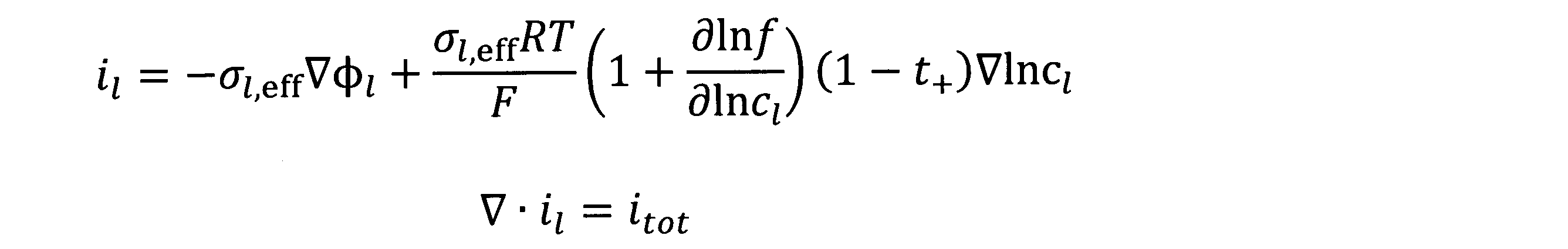
ここで、il は液相電流密度(A/m2 )、σl,effは液相有効伝導率(S/m)、φl は液相電位(V)、Rは気体定数(J/(K・mol))、Tは温度(K)、Fはファラデー定数(C/mol)、fは活量係数、cl は電解質のイオン濃度(mol/m3 )、t+ はカチオン輸率、itot は体積当たりの反応電流密度(A/m3 )である。液相有効伝導率σl,eff は、多孔体中の見かけの伝導率であり、液相バルクの伝導率と固相体積比率εs との関数で表すことが多い。
Here, i l is the liquid phase current density (A / m 2 ), σ l and eff are the liquid phase effective conductivity (S / m), φ l is the liquid phase potential (V), and R is the gas constant (J / m). (K · mol)), T is temperature (K), F is the Faraday constant (C / mol), f is the activity coefficient, c l ion concentration of the electrolyte (mol / m 3), t + is a cation transport number , Itot is the reaction current density per volume (A / m 3 ). The liquid-phase effective conductivity σ l, eff is the apparent conductivity in the porous body, and is often expressed as a function of the liquid-phase bulk conductivity and the solid-phase volume ratio ε s .
電荷保存式は、活物質粒子や集電箔での電子伝導を表す式であり、次式により表される。
The charge conservation formula is a formula that expresses electron conduction in active material particles and a current collector foil, and is expressed by the following formula.

ここで、is は固相電流密度(A/m2 )、φs は固相電位(v)、σs は固相伝導率(S/m)、itot は体積当たりの反応電流密度(A/m3 )である。
Here, i s is the solid phase current density (A / m 2), φ s is the solid phase potential (v), sigma s is the solid phase conductivity (S / m), i tot the reaction current density per volume ( A / m 3 ).
拡散方程式は、活物質粒子中での活物質の拡散を表す方程式であり、次式により表される。
The diffusion equation is an equation that expresses the diffusion of the active material in the active material particles, and is expressed by the following equation.

ここで、cs は固相中の電荷担体濃度(mol/m3 )、tは時間(s)、Ds は固相中の拡散係数(m2 /s)である。
Here, c s is the charge carrier concentration in the solid phase (mol / m 3 ), t is the time (s), and D s is the diffusion coefficient in the solid phase (m 2 / s).
Butler-Volmer式は、固相と液相との界面で起こる電荷移動反応での活性化過電圧を表す式、Nernst式は、開回路電位の定義式であり、それぞれ次式により表される。
The Butler-Volmer equation is an equation that expresses the activation overvoltage in the charge transfer reaction that occurs at the interface between the solid phase and the liquid phase, and the Nernst equation is the definition equation of the open circuit potential, which are expressed by the following equations.

ここで、iloc は反応電流密度(A/m2 )、io は交換電流密度(A/m2 )、αa ,αc は酸化反応、還元反応それぞれの移行係数、ηは活性化過電圧(V)、Eeqは平衡電位(V)、E0 は標準平衡電位(V)、zは価数、aOxは酸化剤濃度(mol/m3 )、aRed は還元剤濃度(mol/m3 )である。Butler-Volmer式およびNernst式は、代替的に実験値に基づき改変した式がしばしば用いられる。例えば、交換電流密度を電荷担体濃度やイオン濃度の関数にしたり、開回路電位としてSOCおよび開回路電位の実測データを用いるなど、適宜に改変してよい。特に、リチウムイオン二次電池においてはSOC及び開回路電位の実測データを用いることが多いので、この後で説明を加える。上述した数1~数4の式における各パラメータを、他の物理値の関数としてもよい。
Here, i loc is the reaction current density (A / m 2 ), io is the exchange current density (A / m 2 ), α a and α c are the transition coefficients of the oxidation reaction and the reduction reaction, and η is the activation overvoltage. (V), E eq is the equilibrium potential (V), E 0 is the standard equilibrium potential (V), z is the valence, a Ox is the oxidizing agent concentration (mol / m 3 ), and a Red is the reducing agent concentration (mol / m /). m 3 ). As the Butler-Volmer equation and the Nernst equation, alternative equations modified based on experimental values are often used. For example, the exchange current density may be made a function of the charge carrier concentration or the ion concentration, or the SOC and the measured data of the open circuit potential may be used as the open circuit potential. In particular, in a lithium ion secondary battery, measured data of SOC and open circuit potential are often used, so a description will be added later. Each parameter in the above-mentioned equations 1 to 4 may be a function of other physical values.
数5に活物質粒子の表面における、固相中の電荷担体濃度と電荷移動反応に関わる電荷担体フラックスの関係式を示す。r0 は活物質粒子の半径(m)を表し、Js は電荷担体のフラックス(mol/m2 s)である。換言すれば、Js は電荷移動反応によって消滅生成する、単位面積単位時間当たりの電荷担体の量である。
Equation 5 shows the relational expression between the charge carrier concentration in the solid phase and the charge carrier flux involved in the charge transfer reaction on the surface of the active material particles. r 0 represents the radius (m) of the active material particles, and J s is the flux of the charge carrier (mol / m 2 s). In other words, J s is the amount of charge carriers per unit area and unit time that is annihilated by the charge transfer reaction.

数6は、電荷担体のフラックスJs と反応電流密度iloc との関係を表す式である。
Equation 6 is an equation expressing the relationship between the flux J s of the charge carrier and the reaction current density i loc .
数7は、反応電流密度iloc と体積当たりの反応電流密度itot との関係を表す式である。Sv は単位体積あたりの表面積、すなわち比表面積(m2 /m3 )を表す。Sv は活物質粒子の半径r0 の関数で表されてもよい。
Equation 7 is an equation expressing the relationship between the reaction current density i loc and the reaction current density i tot per volume. S v represents the surface area per unit volume, that is, the specific surface area (m 2 / m 3 ). S v may be expressed as a function of the radius r 0 of the active material particle.
図6は、典型的な正極材料における固相中の電荷担体濃度と開回路電位(OCP)との関係を示すグラフである。グラフの横軸は、数8によって定義される無次元化電荷担体濃度θであり、電荷担体濃度cs の関数である。グラフの縦軸は、開回路電位(OCP)である。
FIG. 6 is a graph showing the relationship between the charge carrier concentration in the solid phase and the open circuit potential (OCP) in a typical positive electrode material. The horizontal axis of the graph is the dimensionless charge carriers is defined by the number 8 concentration theta, it is a function of charge carrier concentration c s. The vertical axis of the graph is the open circuit potential (OCP).

ここで、csmaxは、電池が全く劣化していない0サイクル時点(例えば電池製造時)における、放電末期(=下限電圧時)の固相中の電荷担体濃度(mol/m3 )である。一方、csminは、電池が全く劣化していない0サイクル時点(例えば電池製造時)における、放電初期(=上限電圧時もしくは満充電時)の固相中の電荷担体(mol/m3 )である。満充電時はcs =csminであるため、θ=0.0であり、放電末期はcs =csmaxであるため、θ=1.0である。電池の放電に伴い、θは平均的には0.0から1.0に変化する。このように、正極の開回路電位OCPは正極における無次元化電荷担体濃度θの関数として表される。同様にして、負極の開回路電位OCPは負極における無次元化電荷担体濃度θの関数として表される。負極において、Csmaxは、電池が全く劣化していない0サイクル時点(例えば電池製造時)における、放電初期(=上限電圧時または満充電時)の固相中の電荷担体濃度(mol/m3 )である。一方、Csminは、電池が全く劣化していない0サイクル時点(例えば電池製造時)における、放電末期(=下限電圧時)の固相中の電荷担体濃度(mol/m3 )である。サーバ装置10の制御部11は、正極のOCPと負極のOCPとを個別に計算することによって、後述する孤立化による劣化を詳細にシミュレーションできる。
Here, c smax is the charge carrier concentration (mol / m 3 ) in the solid phase at the end of discharge (= lower limit voltage) at the time of 0 cycle (for example, at the time of battery manufacturing) when the battery is not deteriorated at all. On the other hand, c smin is a charge carrier (mol / m 3 ) in the solid phase at the initial stage of discharge (= at the upper limit voltage or at the time of full charge) at the time of 0 cycle when the battery is not deteriorated at all (for example, at the time of battery manufacturing). is there. When fully charged, c s = c smin , so θ = 0.0, and at the end of discharge, c s = c smax , so θ = 1.0. As the battery discharges, θ changes from 0.0 to 1.0 on average. As described above, the open circuit potential OCP of the positive electrode is expressed as a function of the dimensionless charge carrier concentration θ in the positive electrode. Similarly, the open circuit potential OCP of the negative electrode is expressed as a function of the nondimensionalized charge carrier concentration θ in the negative electrode. In the negative electrode, C smax is the charge carrier concentration (mol / m 3 ) in the solid phase at the initial stage of discharge (= upper limit voltage or full charge) at the time of 0 cycle when the battery is not deteriorated at all (for example, at the time of battery manufacturing). ). On the other hand, C smin is the charge carrier concentration (mol / m 3 ) in the solid phase at the end of discharge (= lower limit voltage) at the time of 0 cycle (for example, at the time of battery manufacturing) when the battery is not deteriorated at all. By individually calculating the OCP of the positive electrode and the OCP of the negative electrode, the control unit 11 of the server device 10 can simulate the deterioration due to isolation described later in detail.
代替的に、制御部11は、放電時と充電時とで異なる開回路電位OCPの値を用いてもよい。例えば、高エネルギ密度を有する電極材料において、開回路電位OCPは無次元化電荷担体濃度θに対してヒステリシスを有することが確認されている。図7は高エネルギ密度を有する電極材料の無次元化電荷担体濃度θと開回路電位OCPとの関係を示すグラフである。グラフの横軸は無次元化電荷担体濃度θであり、縦軸は開回路電位OCPである。図7のグラフに示すように、同じ無次元化電荷担体濃度θであっても、充電時と放電時とでは開回路電位OCPの値が異なる。このような特性はOCPヒステリシスまたはOCP履歴現象と呼ばれ、しばしば高エネルギー密度を有する電極材料において確認されている。制御部11は、このような電極材料について計算を行う場合、放電時と充電時とで異なる開回路電位OCPの値を用いることにより、精緻なシミュレーションが実現できる。
Alternatively, the control unit 11 may use different open-circuit potential OCP values for discharging and charging. For example, in an electrode material having a high energy density, it has been confirmed that the open circuit potential OCP has hysteresis with respect to the nondimensionalized charge carrier concentration θ. FIG. 7 is a graph showing the relationship between the non-dimensionalized charge carrier concentration θ of the electrode material having a high energy density and the open circuit potential OCP. The horizontal axis of the graph is the non-dimensionalized charge carrier concentration θ, and the vertical axis is the open circuit potential OCP. As shown in the graph of FIG. 7, even if the non-dimensionalized charge carrier concentration θ is the same, the value of the open circuit potential OCP differs between charging and discharging. Such properties are called OCP hysteresis or OCP history phenomena and are often found in electrode materials with high energy densities. When the control unit 11 calculates such an electrode material, a precise simulation can be realized by using different open circuit potential OCP values between the time of discharge and the time of charge.
実施の形態では、リチウムイオン電池の物理モデルの一例としてNewmanモデルを示した。代替的に、電極を単一の活物質粒子によって表現する単粒子モデルが用いられてもよい。単粒子モデルについては、例えば、非特許文献「Single-Particle Model for a Lithium-Ion Cell : Thermal Behavior, Meng Guo, Godfrey Sikha, and Ralph E. White, Journal of The Electrochemical Society ,158 (2) 122-132 (2011)」に開示されたモデルを参照すればよい。充放電特性を表すのであれば、代替的に、等価回路モデルや多項式モデルなどの物理モデル以外のモデルを用いてもよい。すなわち、実測された入出力データからモデルを推定するシステム同定を用いてもよい。システム同定は、入出力データのみからモデルを推定するブラックボックスモデリングであってもよく、システム構造の一部が既知である場合に、既知のシステム構造を反映させ、入出力データに基づきモデルを推定するグレーボックスモデリングであってもよい。多項式モデルについては、例えば、非特許文献「Modeling the Dependence of the Discharge Behavior of a Lithium-Ion Battery on the Environmental Temperature, Ui Seong Kim,a Jaeshin Yi,a Chee Burm Shin, Taeyoung Han,b and Seongyong Park, Journal of The Electrochemical Society,158 (5) 611-618 (2011)」に開示されたモデルを参照すればよい。
In the embodiment, the Newman model is shown as an example of the physical model of the lithium ion battery. Alternatively, a single particle model may be used in which the electrodes are represented by a single active particle. Regarding the single particle model, for example, the non-patent document "Single-Particle Model for a Lithium-Ion Cell: Thermal Behavior, Meng Guo, Godfrey Sikha, and Ralph E. White, Journal of The Electrochemical Society, 158 (2) 122- The model disclosed in "132 (2011)" can be referred to. A model other than the physical model, such as an equivalent circuit model or a polynomial model, may be used instead as long as it expresses the charge / discharge characteristics. That is, system identification that estimates the model from the measured input / output data may be used. The system identification may be black box modeling that estimates the model only from the input / output data, and when a part of the system structure is known, the known system structure is reflected and the model is estimated based on the input / output data. Gray box modeling may be performed. Regarding the polynomial model, for example, the non-patent document “Modeling the Dependence of the Discharge Behavior of a Lithium-Ion Battery on the Environmental Temperature, Ui Seong Kim, a Jaesin Yi, a Chee Burm Shin, Tae The model disclosed in "Journal of The Electrochemical Society, 158 (5) 611-618 (2011)" can be referred to.
以下、蓄電デバイスの劣化メカニズムについて説明する。
第1の劣化メカニズムとして、蓄電デバイスを構成する各要素における電気抵抗の増加について説明する。電気抵抗の増加による劣化メカニズムとは、電解液や電子伝導部材の抵抗率が増加することで電池の内部抵抗が大きくなり、電池の容量が低下する現象である。 Hereinafter, the deterioration mechanism of the power storage device will be described.
As the first deterioration mechanism, an increase in electrical resistance in each element constituting the power storage device will be described. The deterioration mechanism due to an increase in electrical resistance is a phenomenon in which the internal resistance of a battery increases due to an increase in the resistivity of an electrolytic solution or an electron conductive member, and the capacity of the battery decreases.
実施の形態に係るサーバ装置10は、電気抵抗が増大する要因として、(正極、負極)×(集電箔と電極と間の剥離、導電助剤の伝導経路切れ、抵抗体被膜形成)の6種類を含むシミュレーションを実行する。
In the server device 10 according to the embodiment, the factors that increase the electrical resistance are (positive electrode, negative electrode) × (peeling between the current collector foil and the electrode, disconnection of the conductive path of the conductive auxiliary agent, formation of a resistor film). Run a simulation that includes types.
図8は集電箔と電極との間の剥離を説明する説明図である。使用開始直後における蓄電デバイスでは、集電箔と電極(正極又は負極)とが互いに密着した状態にあり、集電箔及び電極間の電気抵抗は比較的小さい。しかしながら、集電箔と電極とは結合性が良いわけではないので、充放電に伴う粒子(電極を構成する活物質粒子)の膨張収縮によって間に亀裂が入り、密着性が低下し、剥離する。この結果、電流の流れる経路が減少し、電気抵抗が増加する。
FIG. 8 is an explanatory diagram for explaining the peeling between the current collector foil and the electrode. In the power storage device immediately after the start of use, the current collector foil and the electrode (positive electrode or negative electrode) are in close contact with each other, and the electrical resistance between the current collector foil and the electrode is relatively small. However, since the current collecting foil and the electrode do not have a good bondability, cracks are formed between the particles (active material particles constituting the electrode) due to the expansion and contraction of the particles (active material particles constituting the electrode), the adhesion is lowered, and the particles are separated. .. As a result, the path through which the current flows decreases and the electrical resistance increases.
図9は導電助剤の伝導経路切れを説明する説明図である。蓄電デバイスにおける電極材料は電子伝導性に劣ることが多いので、アセチレンブラックなどの導電性の導電助剤を少量添加することで導電性を保っている。しかしながら、充放電に伴う粒子(電極を構成する活物質粒子)の膨張収縮によって導電助剤そのものが切断されてしまったり、導電助剤と他の導電助剤、活物質粒子などとの接触が保てなくなったりすることがある。または、導電助剤が化学反応により消失する場合もある。この結果、電流の流れる経路が減少し、電気抵抗が増大する。
FIG. 9 is an explanatory diagram for explaining the disconnection of the conduction path of the conductive auxiliary agent. Since the electrode material in the power storage device is often inferior in electron conductivity, the conductivity is maintained by adding a small amount of a conductive conductive auxiliary agent such as acetylene black. However, the conductive auxiliary agent itself is cut due to the expansion and contraction of the particles (active material particles constituting the electrode) due to charging and discharging, and the contact between the conductive auxiliary agent and other conductive auxiliary agents, active material particles, etc. is maintained. It may disappear. Alternatively, the conductive auxiliary agent may disappear due to a chemical reaction. As a result, the path through which the current flows decreases and the electrical resistance increases.
図10は抵抗体被膜形成を説明する説明図である。充放電に伴って、活物質粒子の表面に抵抗体の被膜が形成される。例えば、リチウムイオン電池の場合、電解液中の有機物とリチウムイオンとからなる化合物による被膜が形成される。このような被膜は、導電性に劣るため電気抵抗が増大する。
FIG. 10 is an explanatory diagram illustrating the formation of the resistor coating. A film of a resistor is formed on the surface of the active material particles as the battery is charged and discharged. For example, in the case of a lithium ion battery, a film composed of a compound composed of an organic substance and lithium ions in the electrolytic solution is formed. Such a coating is inferior in conductivity and therefore has increased electrical resistance.
サーバ装置10の制御部11は、例えば、以下の数9又は数10の式により電気抵抗が増大する速度、すなわち電気伝導率が減少する速度を計算する。
The control unit 11 of the server device 10 calculates, for example, the speed at which the electrical resistance increases, that is, the speed at which the electrical conductivity decreases, according to the following equation (9) or (10).

ここで、rcycle,res はサイクル数によって電気伝導率が減少する速度(S/m/サイクル数)を表す。典型的には、rcycle,res <0である。k0,res は反応速度定数であり、例えばサイクル数の関数である。Ea0,resはサイクル劣化の活性化エネルギ(J/mol)を表し、温度の影響を表す係数である。iは電流密度(A/m2 )であり、||は絶対値を表す。電流密度iの大きさは、電極の膨張収縮速度に関連し、クリープのような歪み速度依存の破壊現象を表す係数である。αres は定数である。k0,res 、Ea0,res、αres の値はユーザが入力してもよく、サーバ装置10において予め設定されてもよい。温度が低下するほど電気伝導率の減少が速くなることが多いため、Ea0,res<0.0であることが好ましい。活物質粒子の膨張収縮が極めて少ない場合、活物質粒子が一次粒子のみからなる場合、バインダによる密着強度が非常に高い場合、または、抵抗体被膜の比抵抗が無視できるほど小さい場合など、電気伝導率の減少を考慮する必要がない場合には、k0,res =0.0とするなど、適宜に無効化してよい。
Here, r cycle and res represent the speed (S / m / number of cycles) at which the electric conductivity decreases depending on the number of cycles. Typically, r cycle, res <0. k 0, res is the reaction rate constant, for example a function of the number of cycles. E a0, res represents the activation energy (J / mol) of cycle deterioration, and is a coefficient representing the influence of temperature. i is the current density (A / m 2 ), and || represents the absolute value. The magnitude of the current density i is a coefficient related to the expansion / contraction rate of the electrode and representing a strain rate-dependent fracture phenomenon such as creep. α res is a constant. The values of k 0, res , E a0, res , and α res may be input by the user or may be preset in the server device 10. Since the decrease in electrical conductivity often becomes faster as the temperature decreases, it is preferable that E a0, res <0.0. Electrical conductivity when the expansion and contraction of the active material particles is extremely small, when the active material particles consist only of primary particles, when the adhesion strength by the binder is very high, or when the specific resistance of the resistor coating is negligibly small. If it is not necessary to consider the decrease in the rate, it may be invalidated as appropriate, such as by setting k 0, res = 0.0.

ここで、rt,res は経過時間によって電気伝導率が減少する速度である(S/m/s)を表す。典型的には、rt,res <0である。k1,res は反応速度定数であり、例えば時間の関数である。代替的に、k1,res は実験データに基づく任意の関数により定義してもよい。Ea1,resは経時劣化の活性化エネルギ(J/mol)を表し、温度の影響を表す係数である。Δtは経過時間(s)である。k1,res 、Ea1,resの値はユーザが入力してもよく、サーバ装置10において予め設定されてもよい。
Here , rt and res represent the speed at which the electric conductivity decreases with the elapsed time (S / m / s). Typically , rt, res <0. k 1 and res are reaction rate constants, for example a function of time. Alternatively, k 1, res may be defined by any function based on experimental data. E a1 and res represent the activation energy (J / mol) of deterioration over time, and are coefficients representing the influence of temperature. Δt is the elapsed time (s). The values of k 1, res and E a 1, res may be input by the user or may be preset in the server device 10.
Nサイクル時点の伝導率をσs (N)とすると、σs (N+1)は、σs (N)にサイクル劣化速度と、1サイクルの経時劣化速度とを足した数11の式により表される。rcycle,res <0及びrt,res <0に注意すると、典型的には、σs (N+1)<σs (N)であり、サイクル数増加や時間の経過と共に、伝導率は低下する。
Assuming that the conductivity at the time of N cycles is σ s (N), σ s (N + 1) is expressed by the equation of number 11 which is the sum of σ s (N), the cycle deterioration rate, and the aging deterioration rate of one cycle. To. Note that r cycle, res <0 and rt , res <0 are typically σ s (N + 1) <σ s (N), and the conductivity decreases with increasing number of cycles and the passage of time. ..
実施の形態では、電気伝導率が減少する速度を数9及び数10の式により計算する構成について説明したが、演算式は例示に過ぎず、実験結果や文献データなどに基づいて自由に改変してもよい。
In the embodiment, the configuration in which the speed at which the electric conductivity decreases is calculated by the equations of the equations 9 and 10, but the arithmetic equation is merely an example and can be freely modified based on the experimental results and literature data. You may.
実施の形態では、電気伝導率が減少する速度をサイクル数または経過時間の関数として計算する構成について説明した。代替的に、制御部11は、SOCの上限及び下限の関数とした数12を用いて、電気抵抗が増加する速度を計算してもよい。ここで、SOCの上限及び下限とは、電池の使用範囲における上限及び下限を表す。
In the embodiment, the configuration in which the rate at which the electric conductivity decreases is calculated as a function of the number of cycles or the elapsed time has been described. Alternatively, the control unit 11 may calculate the rate at which the electrical resistance increases using the number 12 as a function of the upper and lower limits of the SOC. Here, the upper limit and the lower limit of the SOC represent the upper limit and the lower limit in the usage range of the battery.

電気抵抗の増加などの劣化が進行するのは、充放電による膨張収縮による応力が原因と言われている。膨張収縮の大きさはSOCの使用範囲と関係があることが知られており、特にSOCの下限まで使用することで膨張収縮が大きくなることが知られている。そこで、SOCの上限と下限との関数として劣化速度を与えるとよい。通電なしの場合は膨張収縮しないので、サイクル劣化のみを考慮すれば十分であることが多い。制御部11は、SOCの上限値SOCmax と下限値SOCmin とを引数とする関数を因数として乗じた数12により、サイクル数によって電気抵抗が増加する速度を計算できる。上限値SOCmax 及び下限値SOCmin の値はユーザが入力してもよく、サーバ装置10において予め設定されてもよい。多くの場合、(SOCmax -SOCmin )の値が大きくなるほど電気抵抗増大の速度が速くなることが知られているため、(SOCmax -SOCmin )が大きくなるにつれて反応速度が速くなる関数が用いられることが好ましい。
It is said that the progress of deterioration such as an increase in electrical resistance is caused by stress due to expansion and contraction due to charging and discharging. It is known that the magnitude of expansion and contraction is related to the range of use of SOC, and in particular, it is known that expansion and contraction increases when used up to the lower limit of SOC. Therefore, it is advisable to give the deterioration rate as a function of the upper limit and the lower limit of SOC. Since expansion and contraction do not occur when no electricity is applied, it is often sufficient to consider only cycle deterioration. The control unit 11 can calculate the speed at which the electrical resistance increases depending on the number of cycles by the number 12 multiplied by a function having the upper limit value SOC max and the lower limit value SOC min of the SOC as arguments. The upper limit value SOC max and the lower limit value SOC min values may be input by the user or may be preset in the server device 10. In many cases, it is known that the higher the value of (SOC max- SOC min ), the faster the rate of increase in electrical resistance. Therefore, there is a function in which the reaction speed increases as (SOC max- SOC min ) increases. It is preferable to be used.
電気抵抗の増大を決定する速度式の中で、k0,res 、Ea0,res、αres 、k1,res 、Ea1,res、SOCmax 、SOCmin のパラメータを用いたが、これらの値には、集電箔と電極との間の剥離、導電助剤の伝導経路切れ、抵抗体被膜形成に関し、正極及び負極において異なる値を用いてもよい。代替的に、これらの値は、必要に応じて一部または全部を同一の値としてもよい。これらの値は、充電過程と放電過程とで異なる値であってもよい。
The parameters of k 0, res , E a0, res , α res , k 1, res , E a1, res , SOC max , and SOC min were used in the velocity equations that determine the increase in electrical resistance. As the value, different values may be used for the positive electrode and the negative electrode with respect to peeling between the current collector foil and the electrode, breaking the conduction path of the conductive auxiliary agent, and forming a resistor film. Alternatively, some or all of these values may be the same, if desired. These values may be different in the charging process and the discharging process.
第2の劣化メカニズムとして、活物質粒子の孤立化について説明する。活物質粒子の孤立化による劣化メカニズムとは、充放電による膨張収縮を繰り返しにより活物質粒子が割れ、電荷担体の脱挿入ができない領域が徐々に増え、活物質粒子の電荷担体の吸蔵・放出を行える箇所が減り、貯蔵できる電気量、すなわち電池容量が減少する現象である。吸蔵とは、固相内、すなわち活物質粒子内において電荷担体が保持される現象のことである。放出とは、電荷担体が活物質粒子外に排出される現象のことである。
As the second deterioration mechanism, the isolation of active material particles will be explained. The deterioration mechanism due to the isolation of the active material particles is that the active material particles crack due to repeated expansion and contraction due to charging and discharging, the area where the charge carrier cannot be removed and inserted gradually increases, and the charge carrier of the active material particles is stored and released. This is a phenomenon in which the number of places that can be performed decreases and the amount of electricity that can be stored, that is, the battery capacity decreases. Occlusion is a phenomenon in which charge carriers are retained in a solid phase, that is, in active material particles. Release is a phenomenon in which charge carriers are discharged out of active material particles.
サーバ装置10の制御部11は、数13又は数14の式により、活物質粒子の孤立化が進行する速度を計算する。
The control unit 11 of the server device 10 calculates the speed at which the isolation of the active material particles progresses by the formula of the equation 13 or 14.

ここで、rcycle,iso はサイクル数によって活物質粒子の孤立化が進行する速度(1/サイクル数)を表す。典型的には、rcycle,iso <0である。k0,iso は反応速度定数であり、例えばサイクル数の関数である。Ea0,isoはサイクル劣化の活性化エネルギ(J/mol)を表し、温度の影響を表す係数である。iは電流密度(A/m2 )である。電流密度iの大きさは、電極の膨張収縮速度に関連し、クリープや亀裂進展のような歪み速度依存の破壊現象を表す係数である。αiso は定数である。k0,iso 、Ea0,iso、αiso の値はユーザが入力してもよく、サーバ装置10において予め設定されてもよい。
Here, r cycle and iso represent the rate (1 / number of cycles) at which the isolation of the active material particles progresses depending on the number of cycles. Typically, r cycle, iso <0. k 0, iso is the reaction rate constant, for example a function of the number of cycles. E a0, iso represents the activation energy (J / mol) of cycle deterioration, and is a coefficient representing the influence of temperature. i is the current density (A / m 2 ). The magnitude of the current density i is a coefficient related to the expansion / contraction rate of the electrode and representing a strain rate-dependent rupture phenomenon such as creep or crack growth. α iso is a constant. The values of k 0, iso , E a0, iso , and α iso may be input by the user or may be preset in the server device 10.

ここで、rt,iso は経過時間によって活物質粒子の孤立化が進行する速度である(1/s)を表す。典型的には、rt,iso <0である。k1,iso は反応速度定数であり、例えば時間の関数である。代替的に、k1,iso は実験データに基づく任意の関数により定義してもよい。Ea1,isoは経時劣化の活性化エネルギ(J/mol)を表し、温度の影響を表す係数である。Δtは経過時間(s)である。電池内部の応力が低い場合、経時のみによって孤立化が進行することは少ないが、外部から強力な拘束を受けて高応力状態にある場合は無視しがたい。k1,iso 、Ea1,isoの値はユーザが入力してもよく、サーバ装置10において予め設定されてもよい。
Here , rt and iso represent the rate at which the isolation of the active material particles progresses with the elapsed time (1 / s). Typically , rt, iso <0. k 1 and iso are reaction rate constants, for example a function of time. Alternatively, k 1, iso may be defined by any function based on experimental data. E a1 and iso represent the activation energy (J / mol) of deterioration over time, and are coefficients representing the influence of temperature. Δt is the elapsed time (s). When the stress inside the battery is low, isolation rarely progresses only with time, but it cannot be ignored when it is in a high stress state due to strong external restraint. The values of k 1, iso and E a 1, iso may be input by the user or may be preset in the server device 10.
Nサイクル時点の活物質粒子の固相体積比率をεs (N)とすると、εs (N+1)は、εs (N)にサイクル劣化速度と1サイクルの経時劣化速度とを足した数15の式により表される。
Assuming that the solid-state volume ratio of the active material particles at the time of N cycles is ε s (N), ε s (N + 1) is the number 15 obtained by adding the cycle deterioration rate and the aging deterioration rate of one cycle to ε s (N). It is expressed by the formula of.
ここで、活物質粒子の固相体積比率εs が低下すると蓄電デバイスが劣化する、すなわち蓄電デバイスに電荷担体の吸蔵が行える箇所が減り、貯蔵できる電気量すなわち電気容量が減少する理由を説明する。
Here, the reason why the storage device deteriorates when the solid-phase volume ratio ε s of the active material particles decreases, that is, the number of places where the charge carrier can be occluded in the storage device decreases, and the amount of electricity that can be stored, that is, the electric capacity decreases. ..
吸蔵された電荷担体の最小濃度csminと最大濃度csmaxを用いて電気容量の減少を説明する。正極の場合、最大濃度となる放電末期、最小濃度となるのは満充電時である。これらの電荷担体濃度を算出するために必要な体積は、吸蔵された電荷担体が存在できる相の体積である。電極の見かけ体積(例えば、塗工面積×塗工厚み)をVapp (m3 )、製造時の電極に占める活物質粒子の固相体積比率をεs0とすると、吸蔵された電荷担体が存在できる相の体積はVapp εs0である。製造時における電池容量をQ0 (CまたはAh)とすると、数16が成立する。
The decrease in electrical capacity will be described using the minimum and maximum concentrations of c smin and c smax of the occluded charge carriers. In the case of a positive electrode, the maximum concentration is at the end of discharge, and the minimum concentration is at full charge. The volume required to calculate the concentration of these charge carriers is the volume of the phase in which the occluded charge carriers can exist. Assuming that the apparent volume of the electrode (for example, coating area x coating thickness) is V app (m 3 ) and the solid-phase volume ratio of the active material particles in the electrode at the time of manufacture is ε s0 , there is an occluded charge carrier. the volume of the phases that can is V app ε s0. Assuming that the battery capacity at the time of manufacture is Q 0 (C or Ah), the equation 16 holds.
この電池が劣化し、電極の孤立化が進行すると、蓄電に寄与する活物質粒子の固相体積比率εs はεs0よりも低下する。活物質粒子の固相体積比率がεs となったときの電池容量をQとすると、数17が成立する。
This battery is deteriorated, the isolation of the electrodes progresses, solid phase volume ratio epsilon s contributing active material particles in the electric storage is lower than epsilon s0. Assuming that the battery capacity when the solid-state volume ratio of the active material particles is ε s is Q, the equation 17 holds.
数16と数17とから不要な文字を消去し、数18を得る。
Erase unnecessary characters from the numbers 16 and 17 to obtain the number 18.

すなわち、εs がεs0よりも小さくなると、QはQ0 よりも小さくなることが示された。これが、孤立化によって電池容量が低下する理由である。
That is, when epsilon s is smaller than epsilon s0, Q has been shown to be smaller than Q 0. This is the reason why the battery capacity decreases due to isolation.
実施の形態では、活物質粒子の孤立化が進行する速度を数13及び数14の式により計算する構成について説明したが、演算式は例示に過ぎず、実験結果や文献データなどに基づいて自由に改変してもよい。
In the embodiment, the configuration for calculating the speed at which the isolation of the active material particles progresses by the equations of the equations 13 and 14 has been described, but the arithmetic equation is merely an example and is free based on experimental results and literature data. May be modified to.
実施の形態では、活物質粒子の孤立化が進行する速度をサイクル数または経過時間の関数として計算する構成について説明した。代替的にまたは追加的に、制御部11は、通電方向の切り替えが生じるときのSOCの上限及び下限の関数を因数とした数12と同様の式を用いて、活物質粒子の孤立化が進行する速度を計算してもよい。上限値SOCmax 及び下限値SOCmin の値はユーザが入力してもよく、サーバ装置10において予め設定されてもよい。多くの場合、(SOCmax -SOCmin )の値が大きくなるほど孤立化の進行速度が速くなることが知られているため、(SOCmax -SOCmin )が大きくなるにつれて反応速度が速くなる関数が用いられることが好ましい。サイクル数の代わりに、総通電電気量を用いてもよい。
In the embodiment, the configuration for calculating the rate at which the isolation of the active material particles progresses as a function of the number of cycles or the elapsed time has been described. Alternatively or additionally, the control unit 11 uses the same equation as the equation 12 factorized by the function of the upper and lower limits of the SOC when the energization direction is switched, and the isolation of the active material particles proceeds. You may calculate the speed to do. The upper limit value SOC max and the lower limit value SOC min values may be input by the user or may be preset in the server device 10. In many cases, it is known that the larger the value of (SOC max- SOC min ), the faster the isolation progresses. Therefore, the function that the reaction speed increases as (SOC max- SOC min ) increases. It is preferable to be used. The total amount of electricity may be used instead of the number of cycles.

孤立化の進展を決定する速度式の中で、k0,iso 、Ea0,iso、αiso 、k1,iso 、Ea1,iso、SOCmax 、SOCmin のパラメータを用いたが、これらの値は、正極及び負極において異なる値を用いることが望ましい。そのため、電池全体での孤立化の原因のうち、正極の寄与分と負極の寄与分とを分離してシミュレーションできる。活物質粒子の膨張収縮が極めて少ない場合、活物質粒子が一次粒子のみからなる場合など、孤立化を考慮する必要がない場合には、k0,iso =0.0とするなど、適宜に無効化してよい。上記の値は、充電過程と放電過程とで異なる値であってもよい。
In the rate equations that determine the progress of isolation, the parameters k 0, iso , E a0, iso , α iso , k 1, iso , E a1, iso , SOC max , and SOC min were used. It is desirable to use different values for the positive electrode and the negative electrode. Therefore, among the causes of isolation in the entire battery, the contribution of the positive electrode and the contribution of the negative electrode can be separated and simulated. When it is not necessary to consider isolation, such as when the expansion and contraction of the active material particles is extremely small, or when the active material particles consist only of primary particles, it is appropriately invalid such as setting k 0, iso = 0.0. It may be changed. The above values may be different in the charging process and the discharging process.
第3の劣化メカニズムとして、電解液における導電性の低下について説明する。電解液における導電性の低下による劣化メカニズムとは、電荷のキャリアが消失することによる導電性低下、電極体内の微小な気泡発生による導電性の低下、溶媒和の分子構造変化、セパレータの目詰まりなどによって、電解液の抵抗率が増加し、電池の内部抵抗が大きくなり、容量が低下する現象である。電荷のキャリア消失は、主として活物質粒子の表面に抵抗体被膜が形成された場合に生じる。
As the third deterioration mechanism, the decrease in conductivity in the electrolytic solution will be described. The deterioration mechanism due to the decrease in conductivity in the electrolytic solution is the decrease in conductivity due to the disappearance of charge carriers, the decrease in conductivity due to the generation of minute bubbles in the electrode, the change in the molecular structure of solvation, the clogging of the separator, etc. This is a phenomenon in which the resistivity of the electrolytic solution increases, the internal resistance of the battery increases, and the capacity decreases. Charge carrier loss occurs primarily when a resistor coating is formed on the surface of the active material particles.
充放電を繰り返すと、電解液中のリチウムイオンが減少することが知られている。電解液の導電率は、リチウムイオン濃度の関数であり、一般的に初期製造時に最大であるが、リチウムイオン濃度の低下と共に低下することが知られている。図11は電解液中のリチウムイオン濃度とイオン導電率との関係を示すグラフである。図11に示すグラフの横軸は電解液中のリチウムイオン濃度を示し、縦軸はイオン導電率を示している。電解液中のリチウムイオン濃度とイオン導電率との関係は、図11に示すような関係になることが多い。サーバ装置10の制御部11は、導電性の低下速度を、数5及び数6と同様の関数により計算することができる。代替的に、制御部11は、SOCの上限及び下限の関数を因数とした数8と同様の式を用いて、導電性の低下速度を計算してもよい。代替的に、イオンの導電率だけではなく、拡散係数を変更してもよい。
It is known that the lithium ions in the electrolytic solution decrease when charging and discharging are repeated. The conductivity of the electrolytic solution is a function of the lithium ion concentration, and is generally the maximum at the time of initial production, but it is known that the conductivity decreases as the lithium ion concentration decreases. FIG. 11 is a graph showing the relationship between the lithium ion concentration in the electrolytic solution and the ionic conductivity. The horizontal axis of the graph shown in FIG. 11 shows the lithium ion concentration in the electrolytic solution, and the vertical axis shows the ion conductivity. The relationship between the lithium ion concentration in the electrolytic solution and the ionic conductivity is often as shown in FIG. The control unit 11 of the server device 10 can calculate the rate of decrease in conductivity by the same function as in equations 5 and 6. Alternatively, the control unit 11 may calculate the rate of decrease in conductivity using the same equation as in Equation 8 factorized by the functions of the upper and lower limits of SOC. Alternatively, not only the conductivity of the ions but also the diffusion coefficient may be changed.
電解液のリチウムイオン濃度が減少する要因は、ごく微量の電解液の正極での酸化反応の生成物などによって、電解質塩が不溶物として析出することが考えられる。その結果として、負極での電解液の還元分解で消費された電子数よりも多くのリチウムイオンをトラップする反応が生じている。この反応が進むことによって、徐々に電解液中のリチウムイオン濃度が低下し、電導度の低下に繋がる。
It is considered that the reason why the lithium ion concentration of the electrolytic solution decreases is that the electrolyte salt is precipitated as an insoluble matter due to the product of the oxidation reaction of the electrolytic solution at the positive electrode in a very small amount. As a result, a reaction that traps more lithium ions than the number of electrons consumed in the reduction decomposition of the electrolytic solution at the negative electrode has occurred. As this reaction proceeds, the lithium ion concentration in the electrolytic solution gradually decreases, leading to a decrease in conductivity.
第4の劣化メカニズムとして、充放電に関与する電荷担体の減少について説明する。電荷担体の減少による劣化メカニズムとは、充電時に電極の表面で電解液中のイオンが副反応によって消失する現象である。
As the fourth deterioration mechanism, the reduction of charge carriers involved in charging / discharging will be described. The deterioration mechanism due to the decrease in charge carriers is a phenomenon in which ions in the electrolytic solution disappear due to a side reaction on the surface of the electrode during charging.
例えば、リチウムイオン電池の場合、電解液中のリチウムイオンが黒鉛に入る際(すなわち充電の際)、主反応(Li+ +e- +6C→LiC6)以外に、LiC6 が有機物などと反応して抵抗体被膜として電極活物質粒子表面に付着する副反応が生じる。主反応は可逆反応であり、電圧を逆に印加すれば、Li→Li+ +e- の反応が起こるが、副反応は不可逆である。すなわち、一旦抵抗体被膜となってしまったリチウムイオンは以後充放電に参加することができなくなり、容量が低下する。このメカニズムを充放電に関与する電荷担体の減少(若しくは容量バランスずれ)と呼ぶ。第4の劣化メカニズムは、電解液のリチウムイオン濃度が低下することが原因であり、電極材料が劣化するわけではない。すなわち、第4の劣化メカニズムは、解体洗浄後に再利用する余地がある。
For example, a lithium ion battery, when the lithium ion in the electrolyte solution enters the graphite (i.e. during charging), the main reaction - in addition to (Li + + e + 6C → LiC 6), and the reaction LiC 6 and an organic substance A side reaction occurs that adheres to the surface of the electrode active material particles as a resistor film. A main reaction is reversible reaction, when a voltage is applied in the reverse, Li → Li + + e - of the reaction takes place, side reactions are irreversible. That is, the lithium ion once formed as a resistor coating cannot participate in charging / discharging thereafter, and the capacity decreases. This mechanism is called reduction of charge carriers (or capacitance imbalance) involved in charge / discharge. The fourth deterioration mechanism is caused by a decrease in the lithium ion concentration of the electrolytic solution, and does not mean that the electrode material is deteriorated. That is, the fourth deterioration mechanism has room for reuse after dismantling and cleaning.
第4の劣化メカニズムは、リチウムイオン電池の場合、経時及びサイクルの両方によって加速されることが知られている。充電時には、Li+ +e- +6C+P→xLiC6 +(1-x)LiSEI の反応式によって表されるように、Liが生成される主反応(理想的にはx=1)以外に、LiSEI という副生成物が生成される。Pは副生成物の元となる物質である。ここで、x:(1-x)は主反応:副反応の量論比であるが、通常は(1-x)/x<<1であり、副反応の量論係数は非常に小さい。副反応の量論係数に電流密度と電極の表面積を乗じてファラデー定数で割ったリチウムイオンが電解液から消失する。本メカニズムを表現するためには、液相でのLi+ の消失量をJLi+ (mol/m2 s)としたとき、固相へのLiの流入量JLi(mol/m2 s)を、JLi=xJLi+ とすればよい。
The fourth degradation mechanism is known to be accelerated by both time and cycle in the case of lithium-ion batteries. During charging, Li + + e - + 6C + P → xLiC 6 + as represented by (1-x) Li SEI reaction formula, in addition to the main reaction which Li is generated (ideally x = 1), Li SEI By-product is generated. P is a substance that is the source of by-products. Here, x: (1-x) is the stoichiometric ratio of the main reaction: the side reaction, but it is usually (1-x) / x << 1, and the stoichiometric coefficient of the side reaction is very small. Lithium ions, which are obtained by multiplying the stoichiometric coefficient of the side reaction by the current density and the surface area of the electrode and dividing by the Faraday constant, disappear from the electrolytic solution. To express this mechanism, when the amount of Li + disappeared in the liquid phase is J Li + (mol / m 2 s), the amount of Li inflow into the solid phase J Li (mol / m 2 s) , J Li = xJ Li + .
xは適宜に上限値SOCmax 及び下限値SOCmin 、温度T、電流密度iの関数としてよい。例えば、数20に記載するような関数としてもよい。hは実験データに適合するよう定められた任意の関数である。0.0≦x≦1.0であることに注意する。
x may be a function of the upper limit value SOC max, the lower limit value SOC min , the temperature T, and the current density i as appropriate. For example, it may be a function as described in Equation 20. h is an arbitrary function defined to fit the experimental data. Note that 0.0 ≦ x ≦ 1.0.
副反応は充電時以外に、通電をしていなくても生じるが、こちらは実測データを元に、リチウムイオンの消失速度rLiを時間の関数(rLi=g(t))として与えるとよい。関数gとして、時間tの平方根に比例する関数がしばしば用いられる。関数gは、さらに温度に関する因子を含んでもよい。
Side reactions occur even when the power is not supplied, except when charging, but here it is better to give the lithium ion disappearance rate r Li as a function of time (r Li = g (t)) based on the measured data. .. As the function g, a function proportional to the square root of time t is often used. The function g may further include factors relating to temperature.
第4の劣化メカニズムにおける充放電に関与する電荷担体の減少は、第1の劣化メカニズムにおける抵抗体被膜の形成、及び第3の劣化メカニズムにおける電解液における導電性の低下に関係する。すなわち、いずれも電解液中のリチウムイオンが不可逆反応により使われなくなり、電極表面に堆積してしまうことが原因である。本願のシミュレーションでは、従来ばらばらに扱われていたこれらの現象を、関連付けて計算することが可能である。
The decrease in charge carriers involved in charging and discharging in the fourth deterioration mechanism is related to the formation of a resistor coating in the first deterioration mechanism and the decrease in conductivity in the electrolytic solution in the third deterioration mechanism. That is, the cause is that the lithium ions in the electrolytic solution are not used due to the irreversible reaction and are deposited on the electrode surface. In the simulation of the present application, it is possible to correlate and calculate these phenomena, which have been treated separately in the past.
例えば、抵抗体被膜の厚みをδ(m)、質量密度をρfilm(kg/m3 )とした場合に、数21のようになる。Mは被膜物質の分子量(kg/mol)である。
For example, when the thickness of the resistor coating is δ (m) and the mass density is ρ film (kg / m 3 ), the result is as shown in Equation 21. M is the molecular weight (kg / mol) of the coating substance.

数22に示す式は、時刻t(s)までの、電極活物質粒子表面積S(m2 )に亘る被膜形成のために電解液から消失したリチウムイオンの総量(mol)を表す。この式と、第3の劣化メカニズムで述べた電解液中のリチウムイオン濃度低下とを結び付ければ、抵抗体被膜の成長、電解液における導電性の低下、電荷担体の減少を関連付けて計算できる。
The formula shown in Equation 22 represents the total amount (mol) of lithium ions lost from the electrolytic solution due to the formation of a film over the surface area S (m 2 ) of the electrode active material particles up to time t (s). By combining this equation with the decrease in lithium ion concentration in the electrolytic solution described in the third deterioration mechanism, it is possible to calculate the growth of the resistor film, the decrease in conductivity in the electrolytic solution, and the decrease in charge carriers in association with each other.

抵抗体被膜で生じるオーム過電圧は、数23のように表される。ここで、rfilmは抵抗体被膜の抵抗率(Ωm2 )である。
The ohm overvoltage generated by the resistor coating is expressed as Equation 23. Here, r film is the resistivity (Ωm 2 ) of the resistor coating.
以下、サーバ装置10及びクライアント装置20の動作について説明する。
図12はサーバ装置10及びクライアント装置20が実行する処理の手順を説明するフローチャートである。クライアント装置20の制御部21は、ユーザ認証の後にサーバ装置10から送信される表示画面用のデータを受信し、インタフェース画面100を表示部25に表示する(ステップS101)。制御部21は、表示部25に表示したインタフェース画面100を通じて、シミュレーション条件を受付ける(ステップS102)。インタフェース画面100では、例えば、サイクル劣化又は経時劣化の選択、劣化メカニズムの選択、及び電池情報の入力を受付ける。 Hereinafter, the operations of theserver device 10 and the client device 20 will be described.
FIG. 12 is a flowchart illustrating a procedure of processing executed by theserver device 10 and the client device 20. The control unit 21 of the client device 20 receives the data for the display screen transmitted from the server device 10 after the user authentication, and displays the interface screen 100 on the display unit 25 (step S101). The control unit 21 accepts the simulation conditions through the interface screen 100 displayed on the display unit 25 (step S102). The interface screen 100 accepts, for example, selection of cycle deterioration or deterioration over time, selection of deterioration mechanism, and input of battery information.
図12はサーバ装置10及びクライアント装置20が実行する処理の手順を説明するフローチャートである。クライアント装置20の制御部21は、ユーザ認証の後にサーバ装置10から送信される表示画面用のデータを受信し、インタフェース画面100を表示部25に表示する(ステップS101)。制御部21は、表示部25に表示したインタフェース画面100を通じて、シミュレーション条件を受付ける(ステップS102)。インタフェース画面100では、例えば、サイクル劣化又は経時劣化の選択、劣化メカニズムの選択、及び電池情報の入力を受付ける。 Hereinafter, the operations of the
FIG. 12 is a flowchart illustrating a procedure of processing executed by the
制御部21は、インタフェース画面100を通じて受付けたシミュレーション条件を、通信部23を通じてサーバ装置10へ送信する(ステップS103)。
The control unit 21 transmits the simulation conditions received through the interface screen 100 to the server device 10 through the communication unit 23 (step S103).
サーバ装置10は、クライアント装置20から送信されるシミュレーション条件を通信部13にて受信する(ステップS104)。
The server device 10 receives the simulation conditions transmitted from the client device 20 in the communication unit 13 (step S104).
サーバ装置10の制御部11は、通信部13を通じて受信したシミュレーション条件に基づき、シミュレーションを実行する(ステップS105)。このとき、制御部11は、シミュレーション条件に対応するシミュレーションプログラムを選択し、選択したシミュレーションプログラムにシミュレーション条件を適用することによって、蓄電デバイスの劣化をシミュレートする。制御部11は、ステップS104で受信したシミュレーション条件を、ユーザ認証の際に入力されたユーザIDに関連付けて、記憶部12に記憶させてもよい。シミュレーションを実行した場合、制御部11は、通信部13を通じて、計算結果をクライアント装置20へ送信する(ステップS106)。ステップS106では、ある時間ステップ又はあるサイクルにおける計算対象の値(構成部材毎の電気抵抗、孤立化領域の体積割合、電解液の拡散係数またはイオン導電率、電池の膨張率など)が得られる都度、随時計算結果をクライアント装置20へ送信してもよい。
The control unit 11 of the server device 10 executes the simulation based on the simulation conditions received through the communication unit 13 (step S105). At this time, the control unit 11 selects a simulation program corresponding to the simulation conditions and applies the simulation conditions to the selected simulation program to simulate the deterioration of the power storage device. The control unit 11 may store the simulation condition received in step S104 in the storage unit 12 in association with the user ID input at the time of user authentication. When the simulation is executed, the control unit 11 transmits the calculation result to the client device 20 through the communication unit 13 (step S106). In step S106, each time a value to be calculated in a certain time step or a certain cycle (electrical resistance for each component, volume ratio of isolated region, diffusion coefficient or ionic conductivity of electrolytic solution, expansion rate of battery, etc.) is obtained. , The calculation result may be transmitted to the client device 20 at any time.
クライアント装置20は、サーバ装置10から送信される計算結果を通信部23にて受信する(ステップS107)。クライアント装置20の制御部21は、受信した計算結果をシミュレーション中の計算過程として、インタフェース画面100の表示欄130に表示する(ステップS108)。ユーザは、表示欄130に表示される計算過程を参照することにより、サーバ装置10によるシミュレーションが完了したか否かを把握できる。
The client device 20 receives the calculation result transmitted from the server device 10 in the communication unit 23 (step S107). The control unit 21 of the client device 20 displays the received calculation result in the display field 130 of the interface screen 100 as the calculation process during the simulation (step S108). The user can grasp whether or not the simulation by the server device 10 is completed by referring to the calculation process displayed in the display field 130.
次いで、インタフェース画面100においてダウンロードボタン131が操作された場合、制御部21は、通信部23を通じて、シミュレーション結果のダウンロード要求をサーバ装置10へ送信する(ステップS109)。
Next, when the download button 131 is operated on the interface screen 100, the control unit 21 transmits a download request for the simulation result to the server device 10 through the communication unit 23 (step S109).
サーバ装置10は、クライアント装置20からダウンロード要求を受信した場合(ステップS110)、シミュレーション結果をクライアント装置20へ送信する(ステップS111)。ステップS111においてサーバ装置10が送信するシミュレーション結果は、構成部材毎の電気抵抗の値、孤立化領域の体積割合、電解液の拡散係数またはイオン導電率、減少した電荷担体量、初期状態と比較した電池の膨張率などが経過時間やサイクル数と共にどのように変化するのかを示すデータである。シミュレーション結果は、経過時間、サイクル数、及び物理値の3列の数値データであってもよい。代替的に、数値データから生成したグラフ、コンター図又は動画であってもよい。代替的に、商用シミュレーションソフトウェアの形式に従ったライブラリの形式であってもよい。代替的に、電気化学を含む劣化シミュレーション用のシミュレーションプログラムを含んでもよい。ダウンロードするファイル形式は、ユーザが使用する数値解析ソフトウェアやプログラム言語によって、ユーザが希望選択できるようにしてもよい。
When the server device 10 receives the download request from the client device 20 (step S110), the server device 10 transmits the simulation result to the client device 20 (step S111). The simulation result transmitted by the server device 10 in step S111 was compared with the value of the electric resistance for each component, the volume ratio of the isolated region, the diffusion coefficient or ionic conductivity of the electrolytic solution, the reduced amount of charge carriers, and the initial state. It is data showing how the expansion rate of the battery changes with the elapsed time and the number of cycles. The simulation result may be numerical data in three columns of elapsed time, number of cycles, and physical value. Alternatively, it may be a graph, contour diagram or moving image generated from numerical data. Alternatively, it may be in the form of a library that follows the format of commercial simulation software. Alternatively, a simulation program for degradation simulation including electrochemical may be included. The file format to be downloaded may be selected by the user depending on the numerical analysis software or programming language used by the user.
クライアント装置20は、サーバ装置10から送信されるシミュレーション結果を通信部23にて受信する(ステップS112)。クライアント装置20の制御部21は、受信したシミュレーション結果を表示部25に表示させる(ステップS113)。構成部材毎の電気抵抗の値と、電解液の拡散係数またはイオン導電率とが分かると、通電時の発熱量を計算できるので、クライアントは例えば温度のシミュレーションを実施することができる。そのため、冷却設計や熱マネジメントの設計を行うことができる。孤立化領域の体積割合と、減少した電荷担体量とが分かると、電極材料の劣化が分かるので、クライアントは例えばライフサイクル予測や再利用率の予測が可能になる。初期状態と比較した場合の電池の膨張率が分かると、クライアントは例えばモジュールケースや電池の缶筐体などの強度設計が可能になる。
The client device 20 receives the simulation result transmitted from the server device 10 in the communication unit 23 (step S112). The control unit 21 of the client device 20 causes the display unit 25 to display the received simulation result (step S113). Knowing the value of the electrical resistance of each component and the diffusion coefficient or ionic conductivity of the electrolytic solution, the calorific value at the time of energization can be calculated, so that the client can perform, for example, a temperature simulation. Therefore, cooling design and heat management design can be performed. Knowing the volume ratio of the isolated region and the reduced amount of charge carriers, the deterioration of the electrode material can be known, so that the client can predict, for example, the life cycle and the reuse rate. Knowing the expansion coefficient of the battery as compared to the initial state enables the client to design the strength of, for example, a module case or a battery can housing.
劣化に伴う電池の膨張には、電池内部でのガス発生による膨張、電極の割れによる体積膨張、および、充放電に伴う電極の膨張収縮が含まれる。このうち、ガス発生による膨張と、電極の割れによる体積膨張とは、一回の充放電により元の体積より大きくなるような不可逆的な膨張収縮である。一方、充放電に伴う電極の膨張収縮は、一回の充放電を行った後に元の体積に戻るような可逆的な膨張収縮である。
Expansion of the battery due to deterioration includes expansion due to gas generation inside the battery, volume expansion due to cracking of the electrode, and expansion / contraction of the electrode due to charging / discharging. Of these, expansion due to gas generation and volume expansion due to cracking of the electrode are irreversible expansion and contraction that become larger than the original volume by one charge and discharge. On the other hand, the expansion and contraction of the electrode accompanying charge and discharge is a reversible expansion and contraction that returns to the original volume after performing one charge and discharge.
膨張を表す式は、例えば、数24~数26が考えられる。
The formula expressing the expansion can be, for example, several 24 to several 26.
ここで、αgas はガス発生による元の体積に対する線膨張係数である。数24は、ガス発生による膨張を温度Tの関数として表した式である。すなわち、高温ほど蒸気圧が上がるので、電解液の蒸発や電極からの気体の脱離が生じやすい。
Here, α gas is the coefficient of linear expansion with respect to the original volume due to gas generation. Equation 24 is an equation expressing the expansion due to gas generation as a function of the temperature T. That is, since the vapor pressure rises as the temperature rises, evaporation of the electrolytic solution and desorption of gas from the electrodes are likely to occur.
ここで、αcrack は電極割れによる元の体積に対する線膨張係数、εs0は製造時の電極の有効活物質粒子体積割合、εs は任意時点での電極の有効活物質粒子体積割合である。有効活物質粒子体積割合とは、電極の固体部分の体積のうち、孤立化していない部分の体積割合である。活物質粒子が割れて、有効活物質粒子体積割合εs が低下すると、(εs0-εs )は増加する。数25は、電極割れによる膨張を、電極の割れ量を表す(εs0-εs )の関数として表した式である。
Here, alpha crack coefficient of linear expansion of the original volume by the electrode cracking, epsilon s0 effective active material particle volume fraction during manufacture of the electrode, epsilon s is the effective active material particle volume ratio of the electrode at any time. The effective active material particle volume ratio is the volume ratio of the non-isolated portion of the volume of the solid portion of the electrode. When the active material particles are cracked and the effective active material particle volume ratio ε s decreases, (ε s0 −ε s ) increases. Equation 25 is an equation expressing the expansion due to electrode cracking as a function of (ε s0 −ε s ) representing the amount of electrode cracking.
数26は、総線膨張係数を表しており、ガス発生による膨張と、電極割れによる膨張とを引数とした関数である。
The number 26 represents the total linear expansion coefficient, and is a function with the expansion due to gas generation and the expansion due to electrode cracking as arguments.
電池種や電池材料に応じて膨張の式は適宜変更され得るので、上述の数24~数26に限定されるものではない。
The expansion formula can be changed as appropriate depending on the battery type and battery material, and is not limited to the above-mentioned number 24 to number 26.
図13は膨張率の経時変化を示すグラフである。図13に示すグラフの横軸は時間(又はサイクル数)を表し、縦軸は膨張率を表す。電池の膨張率は、図13のグラフに示すように、逓減しつつ単調増加する成分と、充放電に伴い膨張収縮する成分との和になる。前者は不可逆的(塑性的)な膨張であり、後者は可逆的(弾性的)な膨張である。不可逆的な膨張は、経時時間やサイクル数の関数として増加するように与えられ、膨張率と経過時間やサイクル数との関係は実験により取得しておくとよい。実験データを直接用いずに、簡易に行う場合には、経過時間やサイクル数を引数とする等比数列で膨張率を定義することも可能である。例えば、1サイクルでの膨張率の増加分をr(典型的には0<r<1)とすると、Nサイクル後の膨張率はα0 を定数として数27により表される。
FIG. 13 is a graph showing the change over time in the expansion coefficient. The horizontal axis of the graph shown in FIG. 13 represents time (or the number of cycles), and the vertical axis represents the coefficient of expansion. As shown in the graph of FIG. 13, the expansion rate of the battery is the sum of the component that monotonically increases while gradually decreasing and the component that expands and contracts with charging and discharging. The former is an irreversible (plastic) expansion and the latter is a reversible (elastic) expansion. Irreversible expansion is given to increase as a function of time and number of cycles, and the relationship between expansion rate and elapsed time and number of cycles should be obtained experimentally. If the experiment is to be performed simply without using the experimental data directly, it is possible to define the expansion coefficient by a geometric progression with the elapsed time and the number of cycles as arguments. For example, assuming that the increase in the expansion rate in one cycle is r (typically 0 <r <1), the expansion rate after the N cycle is represented by the equation 27 with α 0 as a constant.

劣化シミュレーションモデルは、応力歪みモデルや疲労モデルを含んでもよい。電極材料の多くは、充放電に伴って体積変化を起こすことが知られている。特に、リチウムイオン電池の電極材料においては電荷担体のリチウムの脱挿入に伴う体積変化が顕著である。通常、電池は樹脂材、金属材およびハイテン鋼などで拘束されているため、電極材料が膨張した際には大きな内部応力が発生し、活物質粒子に微小なクラック(亀裂)が生じうる。このクラックは前述の活物質粒子の孤立化の原因となる。そのため、活物質粒子内の応力を高めない設計が望まれる。
The deterioration simulation model may include a stress strain model and a fatigue model. It is known that most of the electrode materials change in volume with charge and discharge. In particular, in the electrode material of a lithium ion battery, the volume change due to the removal and insertion of lithium in the charge carrier is remarkable. Normally, since the battery is restrained by a resin material, a metal material, high-tensile steel, or the like, a large internal stress is generated when the electrode material expands, and minute cracks (cracks) may occur in the active material particles. This crack causes the isolation of the active material particles described above. Therefore, a design that does not increase the stress in the active material particles is desired.
そこで、構造シミュレーションを行う際に、活物質粒子中の電荷担体濃度の関数として歪みを応力-歪み関係式に加えることで、充放電を考慮した電極の膨張収縮による応力歪み計算が可能となる。電荷担体濃度及び歪みの関数形は比例であってもよいし、その他任意の関数であってよい。
Therefore, when performing a structural simulation, by adding strain to the stress-strain relational expression as a function of the charge carrier concentration in the active material particles, it is possible to calculate the stress strain due to expansion and contraction of the electrode in consideration of charge and discharge. The functional form of charge carrier concentration and strain may be proportional or any other function.
例えば、本モデルの電気化学を計算する部分は数値解析ソフトウェアの電気回路網と接続され、応力歪みを計算する部分は市販の数値解析ソフトウェア(有限要素法の構造解析シミュレーションソフトなど)と接続されてもよい。これにより、電池の劣化と応力歪みを同時に連成しつつ計算することも可能となる。
For example, the part that calculates the electrochemical of this model is connected to the electrical network of the numerical analysis software, and the part that calculates the stress strain is connected to the commercially available numerical analysis software (such as structural analysis simulation software of the finite element method). May be good. This makes it possible to calculate the deterioration and stress strain of the battery while simultaneously coupling them.
劣化シミュレーションモデルは、伝熱モデルを含んでもよい。劣化が進行した電池、中でも電気抵抗の増加や電解液における導電性の低下が進行した電池は、発熱量が大きくなる傾向がある。一般には、高温であるほど劣化進行が速くなることが多く、温度管理も電池の劣化を抑制する上で重要な因子である。
The deterioration simulation model may include a heat transfer model. Batteries with advanced deterioration, especially batteries with increased electrical resistance and decreased conductivity in the electrolytic solution, tend to generate a large amount of heat. In general, the higher the temperature, the faster the deterioration progresses, and temperature control is also an important factor in suppressing the deterioration of the battery.
発熱量は、以下の式で算出できる。
(発熱量)=(電流)×(オーム過電圧+活性化過電圧)
=(電流)×(端子間開回路電圧-端子間電圧) The calorific value can be calculated by the following formula.
(Chemical generation) = (Current) x (Ohm overvoltage + Activation overvoltage)
= (Current) x (Terminal open circuit voltage-Terminal voltage)
(発熱量)=(電流)×(オーム過電圧+活性化過電圧)
=(電流)×(端子間開回路電圧-端子間電圧) The calorific value can be calculated by the following formula.
(Chemical generation) = (Current) x (Ohm overvoltage + Activation overvoltage)
= (Current) x (Terminal open circuit voltage-Terminal voltage)
例えば、本モデルの電気化学を計算する部分は数値解析ソフトウェアの電気回路網と接続され、熱を計算する部分は市販の数値解析ソフトウェアの熱回路網計算部分と接続されてもよい。これにより、電池の劣化と発熱を同時に連成しつつ計算することも可能となる。
For example, the part that calculates the electrochemical of this model may be connected to the electric network of the numerical analysis software, and the part that calculates the heat may be connected to the thermal network calculation part of the commercially available numerical analysis software. This makes it possible to calculate the deterioration and heat generation of the battery while simultaneously coupling them.
以上のように、実施の形態では、劣化メカニズムを考慮して蓄電デバイスの劣化をシミュレートし、シミュレーション結果をユーザに提供できる。必要に応じて、蓄電デバイスの劣化をシミュレートした結果として得られる数理モデルをユーザに提供できるので、クライアント装置20では、サーバ装置10からダウンロードした数理モデルを用いて、所望の条件にて蓄電デバイス若しくは蓄電デバイスを含むシステムのシミュレーション結果を取得することができる。クライアント装置20は、シミュレーション結果を算出する際に用いられたシミュレーションプログラムをサーバ装置10からダウンロードしてもよい。
As described above, in the embodiment, the deterioration of the power storage device can be simulated in consideration of the deterioration mechanism, and the simulation result can be provided to the user. If necessary, a mathematical model obtained as a result of simulating the deterioration of the power storage device can be provided to the user. Therefore, in the client device 20, the power storage device is used under desired conditions by using the mathematical model downloaded from the server device 10. Alternatively, the simulation result of the system including the power storage device can be acquired. The client device 20 may download the simulation program used for calculating the simulation result from the server device 10.
クライアント装置20にダウンロードしたシミュレーションプログラムを使用する際、サーバ装置10と通信し、ユーザ認証を受けることを要件としてもよい。その際、クライアント装置20に入力されたシミュレーションの条件はサーバ装置10に送信されてもよい。
When using the simulation program downloaded to the client device 20, it may be a requirement to communicate with the server device 10 and receive user authentication. At that time, the simulation conditions input to the client device 20 may be transmitted to the server device 10.
開示された実施形態は、全ての点において例示であって、制限的なものではない。本発明の範囲は、特許請求の範囲によって示され、特許請求の範囲と均等の意味及び範囲内での全ての変更が含まれる。
The disclosed embodiments are exemplary in all respects and are not restrictive. The scope of the present invention is indicated by the scope of claims and includes all modifications within the meaning and scope equivalent to the scope of claims.
例えば、本実施形態では、電解質が液体の巻回式リチウムイオン電池を例に挙げた。代替的には、全固体リチウムイオン電池、バイポーラ型リチウムイオン電池(電極が電気的直列に接続されたもの)、亜鉛空気電池、ナトリウムイオン電池、鉛電池など電池種に限らず、本願のシミュレーション手法を適用できる。
For example, in the present embodiment, a wound lithium ion battery in which the electrolyte is a liquid is taken as an example. Alternatively, the simulation method of the present application is not limited to battery types such as all-solid-state lithium-ion batteries, bipolar lithium-ion batteries (electrodes connected in series electrically), zinc air batteries, sodium ion batteries, and lead batteries. Can be applied.
本明細書では、サーバ装置10とクライアント装置20との間の通信により、シミュレーションを実施する形態を例示した。代替的に、サーバ管理者がシミュレーションプログラムをDVD-ROMなどの記憶媒体の手段でクライアント利用者に提供し、クライアント端末ローカルでシミュレーションが実施される形態であってもよい。提供手段として、通信を介したダウンロード形式であってもよい。すなわち、クライアント装置20の制御部21が前記シミュレーションプログラムを実行した場合、クライアント装置20は、蓄電デバイスの劣化メカニズムに関する選択情報を受付け、選択された劣化メカニズムを用いて蓄電デバイスの劣化シミュレーションを実行し、シミュレーション結果を出力する本願の開発支援装置として機能するように構成される。
In this specification, a mode in which a simulation is performed by communication between the server device 10 and the client device 20 is illustrated. Alternatively, the server administrator may provide the simulation program to the client user by means of a storage medium such as a DVD-ROM, and the simulation may be performed locally on the client terminal. As a means of providing, a download format via communication may be used. That is, when the control unit 21 of the client device 20 executes the simulation program, the client device 20 receives the selection information regarding the deterioration mechanism of the power storage device, and executes the deterioration simulation of the power storage device using the selected deterioration mechanism. , It is configured to function as a development support device of the present application that outputs simulation results.
10 サーバ装置
11 制御部
12 記憶部
13 通信部
14 操作部
15 表示部
20 クライアント装置
21 制御部
22 記憶部
23 通信部
24 操作部
25 表示部
N 通信網 10Server device 11 Control unit 12 Storage unit 13 Communication unit 14 Operation unit 15 Display unit 20 Client device 21 Control unit 22 Storage unit 23 Communication unit 24 Operation unit 25 Display unit N Communication network
11 制御部
12 記憶部
13 通信部
14 操作部
15 表示部
20 クライアント装置
21 制御部
22 記憶部
23 通信部
24 操作部
25 表示部
N 通信網 10
Claims (14)
- 端末装置のユーザ認証後に、前記端末装置から、蓄電デバイスの劣化メカニズムに関する選択情報を受信する受信部と、
受信した選択情報に基づき、選択された劣化メカニズムを用いて前記蓄電デバイスの劣化をシミュレートするシミュレーション実行部と、
該シミュレーション実行部によるシミュレーション結果、または、前記蓄電デバイスの劣化をシミュレートする際に実行されるシミュレーションプログラムを前記端末装置へ送信する送信部と
を備える開発支援装置。 After user authentication of the terminal device, a receiving unit that receives selection information regarding the deterioration mechanism of the power storage device from the terminal device, and
A simulation execution unit that simulates the deterioration of the power storage device using the selected deterioration mechanism based on the received selection information.
A development support device including a transmission unit that transmits a simulation result by the simulation execution unit or a simulation program executed when simulating deterioration of the power storage device to the terminal device. - 前記シミュレーション実行部は、前記蓄電デバイスを表す物理モデルを用いて、シミュレーションを実行する
請求項1に記載の開発支援装置。 The development support device according to claim 1, wherein the simulation execution unit executes a simulation using a physical model representing the power storage device. - 前記劣化メカニズムは、前記蓄電デバイスを構成する各要素における電気抵抗の増加、活物質粒子の孤立化、電解液における導電性の低下、及び充放電に関与する電荷担体の減少の少なくとも1つを含む
請求項1又は請求項2に記載の開発支援装置。 The deterioration mechanism includes at least one of an increase in electrical resistance in each element constituting the power storage device, isolation of active material particles, a decrease in conductivity in an electrolytic solution, and a decrease in charge carriers involved in charging / discharging. The development support device according to claim 1 or 2. - 前記電気抵抗の増加は、集電箔と多孔体電極との接着部における電気抵抗の増加、活物質粒子中の導電経路の減少に伴う電気抵抗の増加、または、粒子表面の抵抗体被膜の増加に伴う電気抵抗の増加を含む
請求項3に記載の開発支援装置。 The increase in electrical resistance is due to an increase in electrical resistance at the junction between the current collecting foil and the porous electrode, an increase in electrical resistance due to a decrease in the conductive path in the active material particles, or an increase in the resistor coating on the particle surface. The development support device according to claim 3, which includes an increase in electrical resistance accompanying the increase in electrical resistance. - 前記電気抵抗の増加、前記活物質粒子の孤立化、及び前記導電性の低下は、放電時のSOCの上限及び下限の関数により表される
請求項3に記載の開発支援装置。 The development support device according to claim 3, wherein the increase in electrical resistance, the isolation of the active material particles, and the decrease in conductivity are represented by a function of an upper limit and a lower limit of SOC at the time of discharge. - 前記電気抵抗の増加、前記活物質粒子の孤立化、前記導電性の低下、及び前記電荷担体の減少は、経過時間、サイクル数、及び温度の少なくとも1つの関数により表される
請求項3に記載の開発支援装置。 The increase in electrical resistance, the isolation of the active material particles, the decrease in conductivity, and the decrease in charge carriers are expressed by at least one function of elapsed time, number of cycles, and temperature according to claim 3. Development support device. - 前記電荷担体の減少は、充電時における負極表面での電荷移動過程の量論係数により表される
請求項3に記載の開発支援装置。 The development support device according to claim 3, wherein the decrease in the charge carrier is represented by a stoichiometric coefficient of a charge transfer process on the surface of the negative electrode during charging. - 前記シミュレーション結果は、前記蓄電デバイスを構成する各要素における電気抵抗の値、活物質粒子の孤立化領域の体積割合、電解液の拡散係数又はイオン導電率、電荷担体量、及び蓄電デバイスの膨張率のうち、何れか1つの時間変化又はサイクル変化を含む
請求項1から請求項7の何れか1つに記載の開発支援装置。 The simulation results show the value of electrical resistance in each element constituting the power storage device, the volume ratio of the isolated region of the active material particles, the diffusion coefficient or ionic conductivity of the electrolytic solution, the amount of charge carriers, and the expansion rate of the power storage device. The development support device according to any one of claims 1 to 7, which includes any one of the time changes or cycle changes. - 蓄電デバイスの劣化メカニズムに関する選択情報を受付ける受付部と、
受付けた選択情報に基づき、選択された劣化メカニズムを用いて前記蓄電デバイスの劣化をシミュレートするシミュレーション実行部と、
該シミュレーション実行部によるシミュレーション結果、または、前記蓄電デバイスの劣化をシミュレートする際に実行されるシミュレーションプログラムを出力する出力部と
を備える開発支援装置。 The reception department that accepts selection information about the deterioration mechanism of the power storage device,
A simulation execution unit that simulates the deterioration of the power storage device using the selected deterioration mechanism based on the received selection information.
A development support device including an output unit that outputs a simulation result by the simulation execution unit or a simulation program executed when simulating deterioration of the power storage device. - 端末装置と通信可能に接続される開発支援装置を用いて、
蓄電デバイスの劣化メカニズムに関する複数の選択肢を提示し、選択された劣化メカニズムに関する選択情報を前記端末装置から受信し、
受信した選択情報に基づき、選択された劣化メカニズムを用いて前記蓄電デバイスの劣化をシミュレートし、
シミュレーション結果、または、前記蓄電デバイスの劣化をシミュレートする際に実行されるシミュレーションプログラムを前記端末装置へ送信する
開発支援方法。 Using a development support device that is communicatively connected to the terminal device,
A plurality of options regarding the deterioration mechanism of the power storage device are presented, and selection information regarding the selected deterioration mechanism is received from the terminal device.
Based on the received selection information, the deterioration of the power storage device is simulated using the selected deterioration mechanism.
A development support method for transmitting a simulation result or a simulation program executed when simulating deterioration of the power storage device to the terminal device. - コンピュータを用いて、
蓄電デバイスの劣化メカニズムに関する複数の選択肢を提示し、
提示した選択肢に基づき、前記蓄電デバイスの劣化メカニズムに関する選択を受付け、
選択された劣化メカニズムを用いて、前記蓄電デバイスの劣化をシミュレートし、
シミュレーション結果、または、前記蓄電デバイスの劣化をシミュレートする際に実行されるシミュレーションプログラムを出力する
開発支援方法。 Using a computer
Presenting multiple options regarding the deterioration mechanism of power storage devices,
Based on the options presented, accept the selection regarding the deterioration mechanism of the power storage device,
Using the selected degradation mechanism, the degradation of the power storage device is simulated.
A development support method that outputs a simulation result or a simulation program executed when simulating the deterioration of the power storage device. - コンピュータに、
蓄電デバイスの劣化メカニズムに関する複数の選択肢を提示し、選択された劣化メカニズムに関する選択情報を端末装置から受信し、
受信した選択情報に基づき、選択された劣化メカニズムを用いて前記蓄電デバイスの劣化をシミュレートし、
シミュレーション結果、または、前記蓄電デバイスの劣化をシミュレートする際に実行されるシミュレーションプログラムを前記端末装置へ送信する
処理を実行させるためのコンピュータプログラム。 On the computer
It presents multiple options for the deterioration mechanism of the power storage device, receives selection information on the selected deterioration mechanism from the terminal device, and receives the selection information.
Based on the received selection information, the deterioration of the power storage device is simulated using the selected deterioration mechanism.
A computer program for executing a process of transmitting a simulation result or a simulation program executed when simulating deterioration of the power storage device to the terminal device. - コンピュータに、
蓄電デバイスの劣化メカニズムに関する複数の選択肢を提示し、
提示した選択肢に基づき、前記蓄電デバイスの劣化メカニズムに関する選択を受付け、
選択された劣化メカニズムを用いて、前記蓄電デバイスの劣化をシミュレートし、
シミュレーション結果、または、前記蓄電デバイスの劣化をシミュレートする際に実行されるシミュレーションプログラムを出力する
処理を実行させるためのコンピュータプログラム。 On the computer
Presenting multiple options regarding the deterioration mechanism of power storage devices,
Based on the options presented, accept the selection regarding the deterioration mechanism of the power storage device,
Using the selected degradation mechanism, the degradation of the power storage device is simulated.
A computer program for executing a process of outputting a simulation result or a simulation program executed when simulating deterioration of the power storage device. - コンピュータに、
蓄電デバイスの劣化メカニズムに関する複数の選択肢を提示し、
提示した選択肢に基づき、前記蓄電デバイスの劣化メカニズムに関する選択を受付け、
選択された劣化メカニズムを用いて前記蓄電デバイスの劣化をサーバ装置にシミュレートさせるべく、前記劣化メカニズムの選択情報を前記サーバ装置へ送信する
処理を実行させるためのコンピュータプログラム。 On the computer
Presenting multiple options regarding the deterioration mechanism of power storage devices,
Based on the options presented, accept the selection regarding the deterioration mechanism of the power storage device,
A computer program for executing a process of transmitting selection information of the deterioration mechanism to the server device so that the server device can simulate the deterioration of the power storage device using the selected deterioration mechanism.
Priority Applications (3)
| Application Number | Priority Date | Filing Date | Title |
|---|---|---|---|
| EP20777965.3A EP3951995A4 (en) | 2019-03-28 | 2020-03-25 | Development support device, development support method, and computer program |
| CN202080025156.9A CN113646947A (en) | 2019-03-28 | 2020-03-25 | Development support device, development support method, and computer program |
| US17/598,727 US20220188481A1 (en) | 2019-03-28 | 2020-03-25 | Development support device, development support method, and computer program |
Applications Claiming Priority (4)
| Application Number | Priority Date | Filing Date | Title |
|---|---|---|---|
| JP2019-064218 | 2019-03-28 | ||
| JP2019064218 | 2019-03-28 | ||
| JP2020-048369 | 2020-03-18 | ||
| JP2020048369A JP2020167155A (en) | 2019-03-28 | 2020-03-18 | Development support device, development support method, and computer program |
Publications (1)
| Publication Number | Publication Date |
|---|---|
| WO2020196596A1 true WO2020196596A1 (en) | 2020-10-01 |
Family
ID=72609902
Family Applications (1)
| Application Number | Title | Priority Date | Filing Date |
|---|---|---|---|
| PCT/JP2020/013248 WO2020196596A1 (en) | 2019-03-28 | 2020-03-25 | Development support device, development support method, and computer program |
Country Status (3)
| Country | Link |
|---|---|
| US (1) | US20220188481A1 (en) |
| EP (1) | EP3951995A4 (en) |
| WO (1) | WO2020196596A1 (en) |
Citations (8)
| Publication number | Priority date | Publication date | Assignee | Title |
|---|---|---|---|---|
| JPH1114507A (en) | 1997-06-19 | 1999-01-22 | Denso Corp | Vehicle simulation device |
| JP2014077785A (en) * | 2012-09-20 | 2014-05-01 | Sekisui Chem Co Ltd | Storage battery management apparatus, storage battery managing method, and program |
| WO2014132332A1 (en) * | 2013-02-26 | 2014-09-04 | 株式会社 日立製作所 | Degradation estimation device and degradation estimation method |
| WO2014155726A1 (en) * | 2013-03-29 | 2014-10-02 | 株式会社日立製作所 | Method for estimating cell characteristics, device for estimating cell characteristics, and program |
| JP2015215169A (en) * | 2014-05-07 | 2015-12-03 | カルソニックカンセイ株式会社 | Parameter calculation device, parameter calculation method, and program |
| WO2017002292A1 (en) * | 2015-06-30 | 2017-01-05 | ソニー株式会社 | Power storage system, controller, and storage battery charging and discharging method |
| US20180088181A1 (en) * | 2015-07-02 | 2018-03-29 | Huawei Technologies Co., Ltd. | Apparatus and method for detecting battery state of health |
| WO2018147194A1 (en) * | 2017-02-07 | 2018-08-16 | 日本電気株式会社 | Storage battery control device, charging/discharging control method, and recording medium |
Family Cites Families (3)
| Publication number | Priority date | Publication date | Assignee | Title |
|---|---|---|---|---|
| JP4893703B2 (en) * | 2008-07-11 | 2012-03-07 | トヨタ自動車株式会社 | Storage device deterioration display system and storage device deterioration display method |
| JP5586219B2 (en) * | 2009-12-25 | 2014-09-10 | 株式会社東芝 | Diagnostic device, battery pack, and battery value index manufacturing method |
| JP5403191B2 (en) * | 2011-11-08 | 2014-01-29 | 新神戸電機株式会社 | Battery status monitoring system |
-
2020
- 2020-03-25 US US17/598,727 patent/US20220188481A1/en active Pending
- 2020-03-25 EP EP20777965.3A patent/EP3951995A4/en active Pending
- 2020-03-25 WO PCT/JP2020/013248 patent/WO2020196596A1/en unknown
Patent Citations (8)
| Publication number | Priority date | Publication date | Assignee | Title |
|---|---|---|---|---|
| JPH1114507A (en) | 1997-06-19 | 1999-01-22 | Denso Corp | Vehicle simulation device |
| JP2014077785A (en) * | 2012-09-20 | 2014-05-01 | Sekisui Chem Co Ltd | Storage battery management apparatus, storage battery managing method, and program |
| WO2014132332A1 (en) * | 2013-02-26 | 2014-09-04 | 株式会社 日立製作所 | Degradation estimation device and degradation estimation method |
| WO2014155726A1 (en) * | 2013-03-29 | 2014-10-02 | 株式会社日立製作所 | Method for estimating cell characteristics, device for estimating cell characteristics, and program |
| JP2015215169A (en) * | 2014-05-07 | 2015-12-03 | カルソニックカンセイ株式会社 | Parameter calculation device, parameter calculation method, and program |
| WO2017002292A1 (en) * | 2015-06-30 | 2017-01-05 | ソニー株式会社 | Power storage system, controller, and storage battery charging and discharging method |
| US20180088181A1 (en) * | 2015-07-02 | 2018-03-29 | Huawei Technologies Co., Ltd. | Apparatus and method for detecting battery state of health |
| WO2018147194A1 (en) * | 2017-02-07 | 2018-08-16 | 日本電気株式会社 | Storage battery control device, charging/discharging control method, and recording medium |
Non-Patent Citations (3)
| Title |
|---|
| MENG GUOGODFREY SIKHARALPH E. WHITE: "Single-Particle Model for a Lithium-Ion Cell: Thermal Behavior", JOURNAL OF THE ELECTROCHEMICAL SOCIETY, vol. 158, no. 2, 2011, pages 122 - 132 |
| See also references of EP3951995A4 |
| UI SEONG KIMJAESHIN YICHEE BURM SHINTAEYOUNG HANB AND SEONGYONG PARK: "Modeling the Dependence of the Discharge Behavior of a Lithium-Ion Battery on the Environmental Temperature", JOURNAL OF THE ELECTROCHEMICAL SOCIETY, vol. 158, no. 5, 2011, pages 611 - 618 |
Also Published As
| Publication number | Publication date |
|---|---|
| EP3951995A1 (en) | 2022-02-09 |
| US20220188481A1 (en) | 2022-06-16 |
| EP3951995A4 (en) | 2022-10-26 |
Similar Documents
| Publication | Publication Date | Title |
|---|---|---|
| Liu et al. | Electrochemical modeling and parameterization towards control-oriented management of lithium-ion batteries | |
| Liu et al. | A thermal-electrochemical model that gives spatial-dependent growth of solid electrolyte interphase in a Li-ion battery | |
| Purkayastha et al. | An integrated 2-D model of a lithium ion battery: the effect of material parameters and morphology on storage particle stress | |
| CN111505502B (en) | Lithium ion battery aging test method under time-varying cycle working condition based on micro mechanism | |
| US10686321B2 (en) | Secondary battery management | |
| Li et al. | Physics-based CFD simulation of lithium-ion battery under the FUDS driving cycle | |
| Li et al. | Electrochemical and thermal characteristics of prismatic lithium-ion battery based on a three-dimensional electrochemical-thermal coupled model | |
| Tran et al. | A Padé approximate model of lithium ion batteries | |
| JP2020167155A (en) | Development support device, development support method, and computer program | |
| Crawford et al. | Lithium-ion battery physics and statistics-based state of health model | |
| Timms et al. | Asymptotic reduction of a lithium-ion pouch cell model | |
| Zhang et al. | Numerical investigation on the thermal behavior of cylindrical lithium-ion batteries based on the electrochemical-thermal coupling model | |
| CN111999665B (en) | Lithium ion battery aging test method based on micro-mechanism automobile driving condition | |
| WO2020189730A1 (en) | Simulation method, simulation device, and simulation program | |
| Luo et al. | Coupled electrochemical-thermal-mechanical modeling and simulation of lithium-ion batteries | |
| Jiang et al. | A user-friendly lithium battery simulator based on open-source CFD | |
| Liu et al. | Non-uniform heat generation model of pouch lithium-ion battery based on regional heat generation rate | |
| KR20210014000A (en) | Method of Predicting Battery Performance by Mathematical Modeling and Simulation | |
| Bansal et al. | Multiphysics Modeling on the Capacity Degradation of Silicon Anode | |
| WO2020196596A1 (en) | Development support device, development support method, and computer program | |
| Lin et al. | Physics-based and control-oriented modeling of diffusion-induced stress in Li-ion batteries | |
| US11579205B2 (en) | Estimation device, energy storage device, method for estimation, and computer program | |
| JP6699795B1 (en) | Simulation method, simulation device, and computer program | |
| Boovaragavan et al. | A quick and efficient method for consistent initialization of battery models | |
| Same et al. | Effect of thermal parameters on behaviour of A lithium-ion battery: simulation study |
Legal Events
| Date | Code | Title | Description |
|---|---|---|---|
| 121 | Ep: the epo has been informed by wipo that ep was designated in this application |
Ref document number: 20777965 Country of ref document: EP Kind code of ref document: A1 |
|
| NENP | Non-entry into the national phase |
Ref country code: DE |
|
| ENP | Entry into the national phase |
Ref document number: 2020777965 Country of ref document: EP Effective date: 20211028 |