WO2020195032A1 - 電池用集電体、電池、電池用集電体の製造方法、および、電池の製造方法 - Google Patents
電池用集電体、電池、電池用集電体の製造方法、および、電池の製造方法 Download PDFInfo
- Publication number
- WO2020195032A1 WO2020195032A1 PCT/JP2020/001202 JP2020001202W WO2020195032A1 WO 2020195032 A1 WO2020195032 A1 WO 2020195032A1 JP 2020001202 W JP2020001202 W JP 2020001202W WO 2020195032 A1 WO2020195032 A1 WO 2020195032A1
- Authority
- WO
- WIPO (PCT)
- Prior art keywords
- current collector
- region
- battery
- insulating material
- power generation
- Prior art date
- Legal status (The legal status is an assumption and is not a legal conclusion. Google has not performed a legal analysis and makes no representation as to the accuracy of the status listed.)
- Ceased
Links
Images


Classifications
-
- H—ELECTRICITY
- H01—ELECTRIC ELEMENTS
- H01M—PROCESSES OR MEANS, e.g. BATTERIES, FOR THE DIRECT CONVERSION OF CHEMICAL ENERGY INTO ELECTRICAL ENERGY
- H01M4/00—Electrodes
- H01M4/02—Electrodes composed of, or comprising, active material
- H01M4/64—Carriers or collectors
- H01M4/66—Selection of materials
- H01M4/668—Composites of electroconductive material and synthetic resins
-
- H—ELECTRICITY
- H01—ELECTRIC ELEMENTS
- H01M—PROCESSES OR MEANS, e.g. BATTERIES, FOR THE DIRECT CONVERSION OF CHEMICAL ENERGY INTO ELECTRICAL ENERGY
- H01M10/00—Secondary cells; Manufacture thereof
- H01M10/04—Construction or manufacture in general
-
- H—ELECTRICITY
- H01—ELECTRIC ELEMENTS
- H01M—PROCESSES OR MEANS, e.g. BATTERIES, FOR THE DIRECT CONVERSION OF CHEMICAL ENERGY INTO ELECTRICAL ENERGY
- H01M10/00—Secondary cells; Manufacture thereof
- H01M10/05—Accumulators with non-aqueous electrolyte
- H01M10/056—Accumulators with non-aqueous electrolyte characterised by the materials used as electrolytes, e.g. mixed inorganic/organic electrolytes
- H01M10/0561—Accumulators with non-aqueous electrolyte characterised by the materials used as electrolytes, e.g. mixed inorganic/organic electrolytes the electrolyte being constituted of inorganic materials only
- H01M10/0562—Solid materials
-
- H—ELECTRICITY
- H01—ELECTRIC ELEMENTS
- H01M—PROCESSES OR MEANS, e.g. BATTERIES, FOR THE DIRECT CONVERSION OF CHEMICAL ENERGY INTO ELECTRICAL ENERGY
- H01M10/00—Secondary cells; Manufacture thereof
- H01M10/05—Accumulators with non-aqueous electrolyte
- H01M10/058—Construction or manufacture
-
- H—ELECTRICITY
- H01—ELECTRIC ELEMENTS
- H01M—PROCESSES OR MEANS, e.g. BATTERIES, FOR THE DIRECT CONVERSION OF CHEMICAL ENERGY INTO ELECTRICAL ENERGY
- H01M10/00—Secondary cells; Manufacture thereof
- H01M10/05—Accumulators with non-aqueous electrolyte
- H01M10/058—Construction or manufacture
- H01M10/0585—Construction or manufacture of accumulators having only flat construction elements, i.e. flat positive electrodes, flat negative electrodes and flat separators
-
- H—ELECTRICITY
- H01—ELECTRIC ELEMENTS
- H01M—PROCESSES OR MEANS, e.g. BATTERIES, FOR THE DIRECT CONVERSION OF CHEMICAL ENERGY INTO ELECTRICAL ENERGY
- H01M4/00—Electrodes
- H01M4/02—Electrodes composed of, or comprising, active material
- H01M4/64—Carriers or collectors
- H01M4/66—Selection of materials
- H01M4/661—Metal or alloys, e.g. alloy coatings
-
- H—ELECTRICITY
- H01—ELECTRIC ELEMENTS
- H01M—PROCESSES OR MEANS, e.g. BATTERIES, FOR THE DIRECT CONVERSION OF CHEMICAL ENERGY INTO ELECTRICAL ENERGY
- H01M4/00—Electrodes
- H01M4/02—Electrodes composed of, or comprising, active material
- H01M4/64—Carriers or collectors
- H01M4/66—Selection of materials
- H01M4/663—Selection of materials containing carbon or carbonaceous materials as conductive part, e.g. graphite, carbon fibres
-
- H—ELECTRICITY
- H01—ELECTRIC ELEMENTS
- H01M—PROCESSES OR MEANS, e.g. BATTERIES, FOR THE DIRECT CONVERSION OF CHEMICAL ENERGY INTO ELECTRICAL ENERGY
- H01M4/00—Electrodes
- H01M4/02—Electrodes composed of, or comprising, active material
- H01M4/64—Carriers or collectors
- H01M4/66—Selection of materials
- H01M4/665—Composites
- H01M4/667—Composites in the form of layers, e.g. coatings
-
- H—ELECTRICITY
- H01—ELECTRIC ELEMENTS
- H01M—PROCESSES OR MEANS, e.g. BATTERIES, FOR THE DIRECT CONVERSION OF CHEMICAL ENERGY INTO ELECTRICAL ENERGY
- H01M6/00—Primary cells; Manufacture thereof
- H01M6/14—Cells with non-aqueous electrolyte
- H01M6/18—Cells with non-aqueous electrolyte with solid electrolyte
-
- Y—GENERAL TAGGING OF NEW TECHNOLOGICAL DEVELOPMENTS; GENERAL TAGGING OF CROSS-SECTIONAL TECHNOLOGIES SPANNING OVER SEVERAL SECTIONS OF THE IPC; TECHNICAL SUBJECTS COVERED BY FORMER USPC CROSS-REFERENCE ART COLLECTIONS [XRACs] AND DIGESTS
- Y02—TECHNOLOGIES OR APPLICATIONS FOR MITIGATION OR ADAPTATION AGAINST CLIMATE CHANGE
- Y02E—REDUCTION OF GREENHOUSE GAS [GHG] EMISSIONS, RELATED TO ENERGY GENERATION, TRANSMISSION OR DISTRIBUTION
- Y02E60/00—Enabling technologies; Technologies with a potential or indirect contribution to GHG emissions mitigation
- Y02E60/10—Energy storage using batteries
-
- Y—GENERAL TAGGING OF NEW TECHNOLOGICAL DEVELOPMENTS; GENERAL TAGGING OF CROSS-SECTIONAL TECHNOLOGIES SPANNING OVER SEVERAL SECTIONS OF THE IPC; TECHNICAL SUBJECTS COVERED BY FORMER USPC CROSS-REFERENCE ART COLLECTIONS [XRACs] AND DIGESTS
- Y02—TECHNOLOGIES OR APPLICATIONS FOR MITIGATION OR ADAPTATION AGAINST CLIMATE CHANGE
- Y02P—CLIMATE CHANGE MITIGATION TECHNOLOGIES IN THE PRODUCTION OR PROCESSING OF GOODS
- Y02P70/00—Climate change mitigation technologies in the production process for final industrial or consumer products
- Y02P70/50—Manufacturing or production processes characterised by the final manufactured product
Definitions
- the present disclosure relates to a battery current collector, a battery, a method for manufacturing a battery current collector, and a method for manufacturing a battery.
- the current collector for batteries is composed of a material containing an electron conductive material such as metal.
- the battery current collector may be simply referred to as a "current collector” below.
- Patent Document 1 discloses a current collector having an organic structure as a skeleton and a conductive material and having electron conductivity in the film thickness direction.
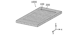
- FIG. 1 is a diagram showing a current collector described in Patent Document 1.
- the current collector 11 is filled in a porous organic structure 1 having a large number of communicating pores in the film thickness direction and a pore portion of the porous organic structure 1. It is composed of the conductive material 2.
- the conductive material 2 is a binder polymer 2b for binding a conductive filler 2a such as a metal powder and the conductive filler 2a to each other, or binding and fixing the conductive filler 2a to the organic structure 1. Consists of.
- the structure is such that it is difficult to short-circuit between the positive electrode and the negative electrode, but the conductive material has an organic structure when the current collector is cut to adjust the shape. There is a possibility that the battery will be exposed from the body, and the electrode layer and the current collector may be displaced during the manufacture or use of the battery, and further improvement in the reliability of the battery using the current collector is desired.
- a current collector for a battery or the like that can improve the reliability of the battery is provided.
- the current collector for a battery includes a first region having electronic conductivity and a second region having insulation properties located around the first region in a plan view.
- the first region contains an insulating material and an electronically conductive material
- the second region contains the insulating material and is located between the first region and the second region in a plan view.
- the third region further includes the insulating material and the solid electrolyte.
- the battery according to one aspect of the present disclosure includes at least one first electrode current collector, at least one second electrode current collector, and at least one power generation element, and the power generation element is the first.
- the first electrode current collector and the second electrode current collector include an electrode layer, a second electrode layer, and a solid electrolyte layer arranged between the first electrode layer and the second electrode layer. It is laminated so as to be arranged in contact with the body, and at least one of the first electrode current collector and the second electrode current collector is the battery current collector.
- the method for manufacturing a current collector for a battery includes a step of preparing a thin film which is an insulating material in which at least one through hole is formed, and an electron conductive material in a region including the through hole.
- a step of preparing a thin film which is an insulating material in which at least one through hole is formed, and an electron conductive material in a region including the through hole.
- the method for manufacturing a battery includes a step of forming a first electrode layer and a second electrode layer, the first electrode layer, the second electrode layer, and the first electrode layer.
- the battery current collector according to the present disclosure can improve the reliability of the battery.
- FIG. 1 is a diagram showing a current collector described in Patent Document 1.
- FIG. 2A is a perspective view showing an example of the current collector according to the first embodiment.
- FIG. 2B is a perspective view showing another example of the current collector according to the first embodiment.
- FIG. 2C is a plan view and a cross-sectional view showing another example of the current collector according to the first embodiment.
- FIG. 2D is a cross-sectional view showing another example of the current collector according to the first embodiment.
- FIG. 3A is a perspective view showing an example of an insulating material used for the current collector according to the first modification of the first embodiment.
- FIG. 3B is a plan view and a cross-sectional view showing an example of the current collector according to the first modification of the first embodiment.
- FIG. 3A is a perspective view showing an example of an insulating material used for the current collector according to the first modification of the first embodiment.
- FIG. 3B is a plan view and a cross-sectional view showing an example of the
- FIG. 3C is a cross-sectional view showing another example of the current collector according to the first modification of the first embodiment.
- FIG. 4A is a perspective view showing an example of an insulating material used for the current collector according to the second modification of the first embodiment.
- FIG. 4B is a plan view and a cross-sectional view showing an example of the current collector according to the second modification of the first embodiment.
- FIG. 5 is a plan view and a cross-sectional view showing an example of the current collector according to the third modification of the first embodiment.
- FIG. 6 is a plan view and a cross-sectional view showing an example of the battery according to the second embodiment.
- FIG. 7 is a plan view and a cross-sectional view showing an example of the battery according to the first modification of the second embodiment.
- FIG. 8 is a plan view and a cross-sectional view showing an example of the battery according to the second modification of the second embodiment.
- FIG. 9 is a cross-sectional view showing an example of the battery according to the modified example 3 of the second embodiment and a diagram showing an example of external connection.
- FIG. 10 is a cross-sectional view showing an example of the battery according to the modified example 4 of the second embodiment.
- FIG. 11A is a cross-sectional view showing an example of the battery according to the modified example 5 of the second embodiment.
- FIG. 11B is a cross-sectional view showing another example of the battery according to the modified example 5 of the second embodiment.
- the current collector for a battery in one aspect of the present disclosure includes a first region having electron conductivity and a second region having insulation properties located around the first region in a plan view.
- the first region includes an insulating material and an electron conductive material, and the second region contains the insulating material.
- an insulating second region is arranged on the outer periphery of the battery current collector, so that the second region of the battery current collector Does not short-circuit even if it comes into contact with another current collector for batteries, so that short-circuiting of the battery is suppressed. Further, even when the second region of the outer peripheral portion of the battery current collector is cut in order to adjust the shape of the current collector, the portion exposed by the cutting is also insulated. Further, since the first region contains an electron conductive material and an insulating material, the electron conductive material is supported on the structure filled with the insulating material or on the insulating material when viewed in the thickness direction.
- the contact area between the insulating material and the electron conductive material is large and the bonding is strong, so that the shape of the current collector can be easily maintained even when it receives an impact or the like. Therefore, the reliability of the battery can be improved.
- the battery current collector is located between the first region and the second region in a plan view, and further includes a third region including the insulating material and the solid electrolyte.
- the battery current collector according to the present disclosure when used for the battery and the third region and the solid electrolyte layer contained in the power generation element are in contact with each other, the solid electrolyte and the solid electrolyte layer contained in the third region are included. Since the solid electrolyte easily adheres to each other, the laminated structure of the battery becomes strong, and the battery current collector and the power generation element are less likely to be displaced from each other. Therefore, the reliability of the battery can be further improved.
- the insulating material may be a thermoplastic resin.
- the insulating material can be processed by heating and cooling, which facilitates the manufacture and post-processing of the current collector for the battery.
- thermoplastic resin may be polyethylene, polypropylene, or polyethylene terephthalate.
- a plurality of through holes may be formed in at least a part of the insulating material in the first region.
- the first region is formed only by filling the through hole with the electron conductive material, and the electron conductivity in the thickness direction can be easily secured.
- the electron conductive material may be a metal foil.
- the first region is formed by attaching the metal foil to the insulating material or sandwiching the insulating material with the metal foil, so that the bonding state between the electron conductive material and the insulating material can be adjusted. It will be easier.
- the electron conductive material may be an aggregate of particulate metal or particulate carbon material.
- the degree of freedom in the shape of the electronically conductive material is increased, so that even when an insulating material having a complicated shape is used, it can be easily manufactured.
- the battery according to one aspect of the present disclosure includes at least one first electrode current collector, at least one second electrode current collector, and at least one power generation element, and the power generation element is the first.
- the first electrode current collector and the second electrode current collector include an electrode layer, a second electrode layer, and a solid electrolyte layer arranged between the first electrode layer and the second electrode layer. It is laminated so as to be arranged in contact with the body, and at least one of the first electrode current collector and the second electrode current collector is the battery current collector.
- the battery uses the above-mentioned current collector for batteries. Therefore, since at least one outer end of the first electrode current collector and the second electrode current collector has an insulating second region, the first electrode current collector and the second electrode current collector come into contact with each other. Even in this case, the short circuit is suppressed. Therefore, the reliability of the battery can be improved.
- the at least one power generation element includes a plurality of power generation elements, and the plurality of power generation elements are located between the first electrode current collector and the second electrode current collector, respectively. They may be laminated so as to be arranged in contact with each other.
- a stacked battery is formed, so a high voltage or high capacity battery can be realized by connecting in series or in parallel.
- the first electrode current collector and the second electrode current collector are the battery current collectors, respectively, and the second region and the second electrode current collector of the first electrode current collector, respectively. At least a part of the second region of the electric body may be bonded.
- the side surface of the power generation element is also covered with the insulating material, so that the power generation element can be prevented from coming into contact with other batteries. Therefore, the reliability of the battery can be further improved.
- An insulating layer made of the insulating material may be formed on the lower surface of the electric body.
- an insulating layer is formed on the upper surface of the current collector laminated on the uppermost layer or the lower surface of the current collector laminated on the lowermost layer. Therefore, it is possible to further reduce the region having electron conductivity on the outer circumference of the battery. Therefore, the possibility of a short circuit due to contact between the batteries is further reduced, and the reliability of the batteries can be further improved.
- the method for manufacturing a current collector for a battery includes a step of preparing a thin film which is an insulating material in which at least one through hole is formed, and an electron conductive material in a region including the through hole.
- a step of preparing a thin film which is an insulating material in which at least one through hole is formed, and an electron conductive material in a region including the through hole.
- the at least one through hole is composed of a plurality of through holes
- the first region is formed by applying a paste containing the electron conductive material to the plurality of through holes. You may.
- the method for manufacturing a battery includes a step of forming a first electrode layer and a second electrode layer, the first electrode layer, the second electrode layer, and the first electrode layer.
- the first electrode current collector and the second electrode current collector are the battery current collectors, respectively, and the second region and the second electrode current collector of the first electrode current collector, respectively. It may include a step of heat-welding at least a part of the electric body with the second region.
- the second region of the first electrode current collector and the second region of the second electrode current collector are heat-welded to each other, and a bonded battery can be manufactured. Since the side surface of the power generation element of the battery manufactured in this manner is also covered with the insulating material, it is possible to prevent the power generation element from coming into contact with other batteries. Therefore, the reliability of the battery can be further improved.
- each figure is a schematic view and is not necessarily exactly illustrated. Therefore, for example, the scales and the like do not always match in each figure. Further, in each figure, substantially the same configuration is designated by the same reference numerals, and duplicate description will be omitted or simplified.
- the x-axis, y-axis and z-axis indicate the three axes of the three-dimensional Cartesian coordinate system.
- the z-axis direction is the thickness direction of the current collector and the battery.
- the "thickness direction” is a direction perpendicular to the main surface of the current collector and each layer constituting the battery.
- plane view means a case where the current collector or the battery is viewed along the thickness direction.
- FIG. 2A is a perspective view showing an example of the current collector according to the first embodiment.
- FIG. 2B is a perspective view showing another example of the current collector according to the first embodiment.
- FIG. 2C is a plan view and a cross-sectional view showing another example of the current collector according to the first embodiment.
- FIG. 2D is a cross-sectional view showing another example of the current collector according to the first embodiment.
- the current collector 1000 is a flat plate-shaped current collector for batteries.
- the shape of the current collector 1000 is not limited as long as it can be used as a current collector for a battery, but it may be any shape as long as each layer of the battery can be laminated on the current collector such as a flat plate or a film. ..
- the current collector 1000 includes a first region 100 having electron conductivity and a second region 200 having insulation properties located around the first region 100 in a plan view.
- the first region 100 contains an insulating material and an electronically conductive material
- the second region 200 contains an insulating material.
- the periphery of the first region 100 is completely surrounded by the second region 200, and the outer circumference of the current collector 1000 is the second region 200.
- the first region 100 has electron conductivity in at least the thickness direction of the current collector 1000, and when the current collector 1000 is used in a battery, a current from the electrode layer can flow at least in the thickness direction. That is, the first region 100 is a region in contact with the electrode layer when the current collector 1000 is used in the battery, and the current from the electrode layer is taken out to the outside or is electrically connected to another electrode layer. Used for connection.
- the insulating material is a material having insulating performance against electrons and ions. Insulation is a property that has insulation performance against electrons and ions.
- the insulating material for example, an inorganic material such as ceramics and glass having no electron and ionic conductivity, and an organic polymer material having no electron and ionic conductivity are used. Since the current collector is preferably lightweight and thin in order to increase the energy density of the battery, the insulating material is easy to process and can be easily reduced in weight and thickness. It is preferable to use an organic polymer material having no electron and ionic conductivity.
- the organic polymer material is preferably a thermoplastic resin from the viewpoint of easy processing and easy heat welding of the insulating materials between the current collectors 1000.
- thermoplastic resin examples include polyethylene, polypropylene, polyethylene terephthalate, polystyrene, vinyl chloride resin, acrylic resin and the like.
- thermoplastic resin is preferably a crystalline polymer material such as polyethylene, polypropylene and polyethylene terephthalate from the viewpoint of toughness, rigidity, processability and the like. The shape of the insulating material will be described later.
- the insulating material a single material may be used, or a mixture of a plurality of materials may be used. Further, the insulating material contained in the first region 100 and the insulating material contained in the second region 200 may have the same shape and material type, or may have different shapes and material types. From the viewpoint of firmly forming the first region 100 and the second region 200, it is said that the insulating material contained in the first region 100 and the insulating material contained in the second region 200 are integrally formed. Good.
- the electron conductive material for example, metals such as aluminum, copper and stainless steel, and carbon materials such as acetylene black, carbon black, graphite, carbon fiber, graphene and carbon nanotubes are used.
- the metal used for the electron conductive material is preferably copper or stainless steel when the current collector 1000 is used as the current collector for the negative electrode, and the current collector 1000 is used as the current collector for the positive electrode. In some cases, it may be aluminum or stainless steel. The shape of the electron conductive material will be described later.
- the thickness of the current collector 1000 is, for example, 5 ⁇ m or more and 100 ⁇ m or less, but is not limited to this.
- the current collector 1001 does not have the second region 200 in a part around the first region 100 in a plan view, and is a part of the first region 100. Is formed up to the end of the current collector 1001.
- the current collector 1001 has electron conductivity at least in the direction perpendicular to the thickness direction, and when used in a battery, draws current from the end of the current collector 1001 in which a part of the first region 100 is formed. be able to.
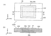
- FIG. 2C (a) is a plan view of the current collector 1002 according to the first embodiment.
- FIG. 2C (b) is a cross-sectional view of the current collector 1002, and represents a cross-sectional view at the position indicated by the line II-II of FIG. 2C (a).
- the current collector 1002 includes a first region 100 and a second region 200 located around the first region 100 in a plan view.
- the current collector 1002 and the first region 100 are rectangular in a plan view, and the second region 200 is a rectangular ring.
- the first region 100 and the second region 200 are formed from the upper surface to the lower surface in the thickness direction (z-axis direction) of the current collector 1002.
- the insulating material 20 in which a plurality of through holes are formed as a whole is filled with the particulate electron conductive material 30 on the central side in a plan view, whereby the first region 100 and the first region 100 and the first Two regions 200 are formed.
- the insulating material 20 has a structure in which a plurality of through holes penetrating from the upper surface to the lower surface in the thickness direction (z-axis direction) are formed.
- the electron conductive material 30 fills the through holes of the insulating material 20.
- the first region 100 has electron conductivity at least in the thickness direction.
- the electron conductive material 30 is preferably an aggregate of particulate metal or particulate carbon material.
- the electron conductive material does not need to be filled in the insulating material, and may be supported on the insulating material when viewed from the thickness direction. That is, the first region is a region in which the insulating material and the electronically conductive material exist when viewed in the thickness direction. Further, in the first region, the electron conductive material is exposed on at least one surface of the upper surface and the lower surface in the thickness direction.
- the insulating material 20 for example, an insulating material in the form of mesh, porous or non-woven fabric is preferably used.
- the through holes are not complicatedly intertwined, so that the first region 100 has a mesh shape. It should be a material.
- the current collector 1001 shown in FIG. 2B when the first region 100 is formed up to the end of the current collector 1001 in a plan view and the current is taken out from the end of the current collector 1001.
- the insulating material is porous in the three-dimensional direction so that the electron conductive material can be easily filled in the direction perpendicular to the thickness direction. It should be a quality shape.
- the insulating material 20 is formed with a plurality of through holes penetrating from the upper surface to the lower surface in the thickness direction (z-axis direction).
- the current collector 1003 includes a first region 100 and a second region 200 located around the first region 100 in a plan view.
- the first region 100 includes two different types of electron conductive materials 30a and electron conductive materials 30b.
- the insulating material 20 and the electron conductive material 30a are contained on the upper surface side in the thickness direction, and the insulating material 20 and the electrons are contained on the lower surface side in the thickness direction.
- the conductive material 30b and the like are included.
- the current collector according to the first embodiment is manufactured by, for example, the following method.
- a paste containing an electron conductive material such as a metal or a carbon material to the region where a plurality of through holes are formed, a plan view is performed, for example, as in the current collector 1002 shown in FIG. 2B.
- the first region 100 which has electron conductivity and contains an insulating material and an electron conductive material, and the insulating material, which has insulation properties and is located around the first region 100 in a plan view, are used.
- a second region 200 containing is formed.
- the paste containing the metal or carbon material is, for example, a paste in which the particulate metal or the particulate carbon material is dispersed in an organic solvent or an adhesive polymer.
- a paste containing an electron conductive material By applying a paste containing an electron conductive material to an insulating material having a plurality of through holes, the inside of the plurality of through holes is filled with the electron conductive material.
- the obtained battery current collector may be dried if necessary.
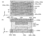
- FIG. 3A is a perspective view showing an example of an insulating material used for the current collector according to the first modification of the first embodiment.
- FIG. 3B is a plan view and a cross-sectional view showing an example of the current collector according to the first modification of the first embodiment.
- FIG. 3C is a cross-sectional view showing another example of the current collector according to the first modification of the first embodiment.
- the current collector according to the first modification of the first embodiment has a different form of through holes of the insulating material used for the current collector as compared with the current collector according to the first embodiment.
- a plurality of through holes are formed in the entire insulating material, but as shown in FIG. 3A, in the first modification of the first embodiment, the frame-shaped (frame-shaped) insulation is formed.
- the sex material 21 is used. That is, the insulating material 21 has a structure in which one through hole 22 is formed.
- the first region is formed so that the through hole 22 is inside the first region in a plan view.
- FIG. 3B (a) is a plan view of the current collector 1100 according to the first modification of the first embodiment. Further, FIG. 3B (b) is a cross-sectional view of the current collector 1100, and represents a cross-sectional view at the position indicated by lines III-III in FIG. 3B (a).
- the current collector 1100 includes a first region 101 having electron conductivity and a second region 201 located around the first region 101 in a plan view and having insulating properties.
- the first region 101 contains the insulating material 23 and the electronically conductive material 31, and the second region 201 contains the insulating material 23.
- the first region 101 of the current collector 1100 is two film-shaped electron conductive materials 31, and includes a region including a through-hole portion of the frame-shaped insulating material 23. It is formed so as to sandwich it.
- the electron conductive material 31 may be a metal foil.
- the electron conductivity in the first region 101 can be enhanced.
- the insulating material 23 does not have a through hole.
- the current collector 1101 includes a first region 101 and a second region 201 located around the first region 101 in a plan view.
- the first region 101 includes two different types of electron conductive material 31a and electron conductive material 31b.
- the first region 101 of the current collector 1101 is formed by two film-shaped electron conductive materials 31a and electron conductive material 31b so as to sandwich a region including a through hole portion of the frame-shaped insulating material 23. There is. Specifically, in the first region 101, the electron conductive material 31a is supported on a part of the insulating material 23 on the upper surface side in the thickness direction, and the insulating material 23 is supported on the lower surface side in the thickness direction. The electron conductive material 31b is supported on a part of the above.
- the current collector according to the first modification of the first embodiment is manufactured by, for example, the following method.
- a thin film such as the insulating material 21 shown in FIG. 3A, which is a frame-shaped insulating material having one through hole formed in the center, is prepared.
- the current collector 1100 shown in FIG. 3B has electron conductivity in a plan view. It forms a first region 101 containing an insulating material and an electronically conductive material, and a second region 201 having insulating properties and located around the first region 101 in a plan view and containing the insulating material.
- a method for bonding metal foils known methods such as resistance welding, ultrasonic welding, a method using conductive double-sided tape or a conductive paste can be used.
- FIG. 4A is a perspective view showing an example of an insulating material used for the current collector according to the second modification of the first embodiment.
- FIG. 4B is a plan view and a cross-sectional view showing an example of the current collector according to the second modification of the first embodiment.
- the current collector according to the second modification of the first embodiment has a different form of through holes of the insulating material used for the current collector as compared with the current collector according to the first embodiment.
- a plurality of through holes are formed in the entire insulating material forming the current collector, but as shown in FIG. 4A, in the second modification of the first embodiment, a plan view is obtained.
- the insulating material 24 in which a plurality of through holes are formed only in the central region 25 is used.
- the first region is formed so that the region 25 is inside the first region in a plan view.
- FIG. 4B (a) is a plan view of the current collector 1200 according to the second modification of the first embodiment. Further, FIG. 4B (b) is a cross-sectional view of the current collector 1200, and represents a cross-sectional view at the position indicated by the IV-IV line of FIG. 4B (a).
- the current collector 1200 is located around the first region 102 having electron conductivity and the first region 102 in a plan view, and has an insulating property second region 202. And.
- the first region 101 contains the insulating material 26, the electron conductive material 30a, and the electron conductive material 30b, and the second region contains the insulating material 26.
- the insulating material 26 and the electron conductive material 30a are contained on the upper surface side in the thickness direction, and the lower surface side in the thickness direction. , Insulating material 26 and electron conductive material 30b are included.
- the electron conductive material 30a and the electron conductive material 30b are filled in a plurality of through holes formed in the insulating material 26. Further, a part of the electron conductive material 30a and the electron conductive material 30b is supported in a region 27 in which a plurality of through holes of the insulating material 26 are formed and a region outside the region 27 when viewed from the thickness direction.
- the electron conductive material 30a and the electron conductive material 30b are, for example, a particulate metal or a particulate carbon material.
- the first modification of the first embodiment and the second modification of the first embodiment when the current collector is used for the battery,
- the outermost peripheral end of the battery contains an insulating material, and a second region having an insulating property is arranged so that the battery does not short-circuit even if it comes into contact with the first region of an adjacent current collector. ..
- the electron conductive material in the first region has a structure filled with the insulating material or a structure supported on the insulating material when viewed in the thickness direction, the insulating material and the electron conduction Since the area of contact with the material is large and the bonding is strong, the shape of the current collector can be easily maintained even when it receives an impact or the like. Therefore, the reliability of the battery can be improved.
- FIG. 5 is a plan view and a cross-sectional view showing an example of the current collector according to the third modification of the first embodiment.
- the current collector according to the third modification of the first embodiment is different from the current collector according to the first embodiment in that it includes a third region including an insulating material and a solid electrolyte.
- FIG. 5A is a plan view of the current collector 1300 according to the third modification of the first embodiment. Further, FIG. 5B is a cross-sectional view of the current collector 1300, and represents a cross-sectional view at a position indicated by a line VV in FIG. 5A.
- the current collector 1300 has electron conductivity, and includes a first region 100 including an insulating material 20 and an electron conductive material 30. It has an insulating property, is located around the first region 100 in a plan view, and includes a second region 200 including an insulating material 20. Further, the current collector 1300 is located between the first region 100 and the second region 200 in a plan view, and includes a third region 300 including the insulating material 20 and the solid electrolyte 40. As shown in FIG. 5B, the third region 300 is formed from the upper surface to the lower surface in the thickness direction (z-axis direction). The third region 300 of the current collector 1300 is formed by filling a plurality of through holes formed in the insulating material 20 with the particulate solid electrolyte 40.
- the third region 300 is formed by filling the plurality of through holes of the insulating material 20 with the solid electrolyte 40.
- the solid electrolyte 40 does not need to be filled in the insulating material, and may be supported on the insulating material when viewed from the thickness direction. That is, the third region is a region where the insulating material and the solid electrolyte are present when viewed in the thickness direction. Further, in the third region 300, the solid electrolyte 40 is exposed on at least one surface of the upper surface and the lower surface in the thickness direction.
- the solid electrolyte 40 is a material having conduction performance with respect to ions and insulation performance with respect to electrons.
- a solid electrolyte such as an inorganic solid electrolyte can be used.
- an inorganic solid electrolyte a sulfide solid electrolyte, an oxide solid electrolyte, a halide solid electrolyte and the like can be used.
- a sulfide solid electrolyte for example, a mixture of lithium sulfide (Li 2 S) and diphosphorus pentasulfide (P 2 S 5 ) can be used.
- the insulating material contained in the first region 100 and the second region 200 and the insulating material contained in the third region 300 may have the same shape and material type, or may have different shapes and material types. Good. From the viewpoint of firmly forming the first region 100, the second region 200, and the third region 300, the insulating materials contained in the first region 100, the second region 200, and the third region 300 are integrally formed. It is good to have.
- the third region 300 uses the same method as the method for forming the first region in the method for producing the current collector according to each of the first and first modifications, and the electron conductive material is made into a solid electrolyte.
- a third region can be formed by modifying and placing a solid electrolyte between the first and second regions.
- the adhesiveness between the power generation element of the battery, particularly the solid electrolyte layer, and the solid electrolyte 40 in the third region 300 is improved when used in the battery, and the battery It is possible to reduce the possibility that the power generation element and the current collector are displaced during manufacturing or use. Therefore, the current collector 1300 can further improve the reliability of the battery.
- FIG. 6 is a plan view and a cross-sectional view showing an example of the battery according to the second embodiment.
- the battery according to the second embodiment is a battery including the current collector according to the first embodiment and each modification described above. That is, the current collector of the battery according to the second embodiment includes a first region and a second region, or a first region, a second region, and a third region.
- FIG. 6A is a plan view of the battery 2000 according to the second embodiment.
- FIG. 6B is a cross-sectional view of the battery 2000, and represents a cross-sectional view at a position indicated by the VI-VI line in FIG. 6A.
- the battery 2000 includes a current collector 1300a, a current collector 1300b, and a power generation element 500.
- the power generation element 500 includes a positive electrode layer 510, a negative electrode layer 520, and a solid electrolyte layer 530 arranged between the positive electrode layer 510 and the negative electrode layer 520.
- the power generation elements 500 are laminated so as to be arranged so as to be in contact with the current collector 1300a and the current collector 1300b.
- the solid electrolyte layer 530 is also arranged outside the positive electrode layer 510 and the negative electrode layer 520 in a plan view, and a part of the solid electrolyte layer 530 is in contact with the current collector 1300a and the current collector 1300b.
- the current collector 1300a and the current collector 1300b are current collectors having the same structure as the current collector 1300 according to the third modification of the first embodiment.
- the electron conductive material 30a contained in the first region 100a of the current collector 1300a and the electron conductive material 30b contained in the first region 100b of the current collector 1300b are electron conductive materials composed of different materials. is there.
- the current collector 1300a is an example of a first electrode current collector
- the current collector 1300b is an example of a second electrode current collector.
- the positive electrode layer 510 is an example of the first electrode layer
- the negative electrode layer 520 is an example of the second electrode layer.
- both the current collector 1300a and the current collector 1300b were current collectors having the same structure as the current collector 1300 according to the third modification of the first embodiment, but only one of them was implemented. It may be a current collector having the same structure as the current collector 1300 according to the third modification of the first embodiment.
- the positive electrode layer 510 is laminated so as to be in contact with the first region 100a of the current collector 1300a, and all of the positive electrode layer 510 is located inside the first region 100a in a plan view.
- the negative electrode layer 520 is laminated so as to be in contact with the first region 100b of the current collector 1300b, and all of the negative electrode layer 520 is located inside the first region 100b in a plan view.
- the solid electrolyte layer 530 is also arranged in contact with the side surfaces of the positive electrode layer 510 and the negative electrode layer 520 when viewed from the thickness direction. That is, the solid electrolyte layer 530 is also arranged outside the positive electrode layer 510 and the negative electrode layer 520 in a plan view. Therefore, a part of the solid electrolyte layer 530 is laminated so as to be in contact with the first region 100a and the third region 300a of the current collector 1300a and the first region 100b and the third region 300b of the current collector 1300b. ..
- an insulating second region 200a and a second region 200b are arranged at the outer end of the battery 2000 in a plan view.
- the positive electrode layer 510 is a layer containing a positive electrode material such as an active material.
- the positive electrode layer 510 contains, for example, a positive electrode active material.
- the material of the positive electrode active material various materials capable of separating and inserting ions such as lithium, sodium, potassium and magnesium can be used.
- Examples of the positive electrode active material contained in the positive electrode layer 510 include materials capable of releasing and inserting lithium ions, for example, lithium cobalt oxide composite oxide (LCO), lithium nickel oxide composite oxide (LNO), and manganese.
- Lithium Acid Lithium Composite Oxide (LMO), Lithium-manganese-Nickel Composite Oxide (LMNO), Lithium-Manga-Cobalt Composite Oxide (LMCO), Lithium-Nickel-Cobalt Composite Oxide (LNCO), Lithium-Nickel-Manganes -Positive electrode active materials such as cobalt composite oxide (LNMCO) can be used.
- a solid electrolyte such as an inorganic solid electrolyte may be used.
- an inorganic solid electrolyte a sulfide solid electrolyte, an oxide solid electrolyte, or the like can be used.
- a sulfide solid electrolyte for example, a compound composed of lithium sulfide (Li 2 S) and diphosphorus pentasulfide (P 2 S 5 ) can be used.
- Li 2 S-SiS 2, Li 2 S-B 2 S 3, Li 2 S-GeS 2 may sulfide is used, such as, as an additive to the sulfide Sulfide to which at least one of 3 N, LiCl, LiBr, Li 3 PO 4 and Li 4 SiO 4 has been added may be used.
- oxide-based solid electrolyte examples include Li 7 La 3 Zr 2 O 12 (LLZ), Li 1.3 Al 0.3 Ti 1.7 (PO 4 ) 3 (LATP), (La, Li) TiO 3 (LLTO) and the like can be used.
- the surface of the positive electrode active material may be coated with a solid electrolyte.
- a conductive material such as acetylene black, carbon black, graphite or carbon fiber, or a binder for binding such as polyvinylidene fluoride may be used.
- the positive electrode layer 510 can be produced, for example, by applying and drying a paste-like paint in which the material contained in the positive electrode layer 510 is kneaded together with a solvent on the surface of the current collector. In order to increase the density of the positive electrode layer 510, the positive electrode plate containing the positive electrode layer 510 and the current collector may be pressed after drying.
- the thickness of the positive electrode layer 510 is, for example, 5 ⁇ m or more and 300 ⁇ m or less, but is not limited to this.
- the negative electrode layer 520 is a layer containing a negative electrode material such as an active material.
- the negative electrode layer 520 contains, for example, a negative electrode active material as an electrode material.
- a negative electrode active material such as graphite or metallic lithium can be used.
- various materials capable of separating and inserting ions such as lithium, sodium, potassium and magnesium can be used.
- a solid electrolyte such as an inorganic solid electrolyte may be used.
- the inorganic solid electrolyte the material exemplified as the inorganic solid electrolyte used for the above-mentioned positive electrode layer 510 can be used.
- a conductive material such as acetylene black, carbon black, graphite or carbon fiber, or a binder for binding such as polyvinylidene fluoride may be used.
- the negative electrode layer 520 can be produced, for example, by applying and drying a paste-like paint in which the material contained in the negative electrode layer 520 is kneaded together with a solvent on the surface of the current collector. In order to increase the density of the negative electrode layer 520, the negative electrode plate containing the negative electrode layer 520 and the current collector may be pressed after drying.
- the thickness of the negative electrode layer 520 is, for example, 5 ⁇ m or more and 300 ⁇ m or less, but is not limited to this.
- the solid electrolyte layer 530 is a layer containing an electrolyte material.
- the electrolyte material a generally known electrolyte for batteries can be used.
- the thickness of the solid electrolyte layer 530 may be 5 ⁇ m or more and 300 ⁇ m or less, or 5 ⁇ m or more and 100 ⁇ m or less.
- the solid electrolyte layer 530 may contain a solid electrolyte.
- the battery 2000 may be, for example, an all-solid-state battery.
- the solid electrolyte for example, a solid electrolyte such as an inorganic solid electrolyte can be used.
- the inorganic solid electrolyte the material exemplified as the inorganic solid electrolyte used for the above-mentioned positive electrode layer 510 can be used.
- the solid electrolyte layer 530 may contain, for example, a binder such as polyvinylidene fluoride.
- the solid electrolyte layer 530 is formed, for example, by forming a paste-like paint obtained by kneading the material contained in the solid electrolyte layer 530 together with a solvent on the positive electrode layer 510 formed on the current collector and / or on the current collector. It can be produced by coating and drying on the negative electrode layer 520.
- the above-mentioned solid electrolyte layer 530 is laminated so as to be arranged between the positive electrode layer 510 formed on the current collector and the negative electrode layer 520 formed on the current collector.
- the power generation elements 500 are stacked so as to be arranged between the current collectors.
- the second region 200a and the second region 200b having insulation properties are arranged at the outer ends of the battery 2000, a short circuit is suppressed even when the current collectors come into contact with each other. Further, since the third region 300a and the third region 300b containing the solid electrolyte are in contact with the solid electrolyte layer 530, the solid electrolyte of the third region 300a and the third region 300b and the solid electrolyte of the solid electrolyte layer 530 can be separated from each other. Since it is easy to adhere, the battery 2000 has a structure in which the batteries are firmly laminated. Therefore, a battery with further improved reliability can be realized.
- FIG. 7 is a plan view and a cross-sectional view showing an example of the battery according to the first modification of the second embodiment.
- the battery according to the first modification of the second embodiment is different from the battery according to the first embodiment in that the second region of the two current collectors is joined.
- FIG. 7A is a plan view of the battery 2100 according to the first modification of the second embodiment. Further, FIG. 7 (b) is a cross-sectional view of the battery 2100, and represents a cross-sectional view at the position indicated by the line VII-VII of FIG. 7 (a).
- the battery 2100 includes a current collector 1300c, a current collector 1300d, and a power generation element 500a.
- the current collector 1300c is an example of a first electrode current collector
- the current collector 1300d is an example of a second electrode current collector.
- the second region 200c of the current collector 1300c and the second region 200d of the current collector 1300d are joined.
- the side surface of the power generation element 500a of the battery 2100 when viewed from the thickness direction is covered with the insulating material 250 contained in the second region 200c and the second region 200.
- a part of the first region 100c of the current collector 1300c is formed up to the end of the current collector 1300c, and a part of the first region 100d of the current collector 1300d reaches the end of the current collector 1300d. It is formed. That is, except for the portions of the first region 100c and the first region 100d formed for extracting the current, the outer periphery of the side surface of the battery 2100 as viewed from the thickness direction is covered with the insulating material 250.
- the battery 2100 according to the first modification of the second embodiment is manufactured by, for example, the following method.
- the power generation element 500a including the positive electrode layer 510, the negative electrode layer 520, and the solid electrolyte layer 530 is placed between the current collector 1300c and the current collector 1300d in the same manner as the battery 2000 of the second embodiment. Laminate so that they are arranged in.
- the battery 2100 is obtained by heat-welding (heat-sealing) the second region 200c and the second region 200d of the obtained laminate.
- the insulating material contained in the second region 200c and the second region 200d is preferably a thermoplastic resin from the viewpoint of facilitating heat welding.
- the side surface of the power generation element 500a is also covered with an insulating material, it is possible to prevent the power generation element 500a from coming into contact with another battery. Therefore, a battery with further improved reliability can be realized.
- FIG. 8 is a plan view and a cross-sectional view showing an example of the battery according to the second modification of the second embodiment.
- the battery according to the second modification of the second embodiment is different from the battery according to the first embodiment in that it includes two power generation elements.
- FIG. 8A is a plan view of the battery 2200 according to the second modification of the second embodiment. Further, FIG. 8B is a cross-sectional view of the battery 2200, and represents a cross-sectional view at the position indicated by the line VIII-VIII in FIG. 8A.
- the battery 2200 includes a current collector 1300e, a current collector 1300f, a current collector 1300g, a power generation element 500b, and a power generation element 500c.
- the current collector 1300f is an example of a first electrode current collector
- the current collector 1300e and the current collector 1300g are examples of a second electrode current collector.
- the battery includes a plurality of first electrode current collectors or a plurality of second electrode current collectors
- the plurality of first electrode current collectors and the plurality of second electrode current collectors have the same structure. It may be a body or a current collector having a different structure.
- the power generation element 500b is laminated in contact with the upper surface of the current collector 1300f, and the power generation element 500c is laminated in contact with the lower surface of the current collector 1300f.
- the power generation element 500b is arranged between the current collector 1300e and the current collector 1300f, and the power generation element 500c is arranged between the current collector 1300f and the current collector 1300g.
- the positive electrode layer 510 of the power generation element 500b and the positive electrode layer 510 of the power generation element 500c are both laminated so as to be in contact with the first region 100f of the current collector 1300f.
- the solid electrolyte layer 530 of the power generation element 500b and the solid electrolyte layer 530 of the power generation element 500c are both laminated so as to be in contact with the third region 300f of the current collector 1300f. That is, in the battery 2200, the power generation element 500b has a laminated structure in which the power generation element 500b and the power generation element 500c are laminated in a vertically inverted stacking order. As a result, the battery 2200 has a laminated structure formed as a parallel-connected laminated battery.
- the first as a current collector located in contact between the two power generation elements.
- a current collector having a region, a second region, and a third region in FIG. 8, a current collector having the first region 100f, the second region 200f, and the third region 300f
- Batteries can be configured.
- the solid electrolyte in the third region of the current collector located between the two power generation elements contacts the adjacent solid electrolyte layer and functions like a liquid junction that conducts ions between the two power generation elements. To do.
- the capacity of the batteries can be increased.
- the second insulating region is arranged at the outer end of the current collector when viewed from the thickness direction, short circuits are suppressed even when the current collectors come into contact with each other. Will be done.
- the third region containing the solid electrolyte is in contact with the solid electrolyte layer, the solid electrolyte in the third region and the solid electrolyte in the solid electrolyte layer are easily adhered to each other, so that the laminated battery is firmly laminated.
- the structure makes it difficult for the power generation element and the current collector to shift. Therefore, a battery with further improved reliability can be realized.
- FIG. 9 is a cross-sectional view showing an example of the battery according to the modified example 3 of the second embodiment and a diagram showing an example of external connection.
- the battery according to the third modification of the second embodiment is the same as the battery according to the second modification of the second embodiment in that it has two power generation elements, but is connected in series and in parallel by external connection. The difference is that any of the above connection forms is possible.
- FIG. 9A is a cross-sectional view of the battery 2300 according to the third modification of the second embodiment.
- (B) and (c) of FIG. 9 show an example of external connection of the battery 2300.
- the battery 2300 includes a current collector 1200a, a current collector 1200b, a current collector 1200c, a power generation element 500d, and a power generation element 500e.
- the current collector 1200b is an example of a first electrode current collector
- the current collector 1200a and the current collector 1200c are examples of a second electrode current collector.
- the power generation element 500d is laminated in contact with the upper surface of the current collector 1200b, and the power generation element 500e is laminated in contact with the lower surface of the current collector 1200b.
- the power generation element 500d is arranged between the current collector 1200a and the current collector 1200b, and the power generation element 500e is arranged between the current collector 1200b and the current collector 1200c.
- the positive electrode layer 510 of the power generation element 500d and the positive electrode layer 510 of the power generation element 500e are both laminated so as to be in contact with the first region 102b of the current collector 1200b.
- the current collector 1200b includes a third region 302b in which a solid electrolyte is supported on the insulating material 28, outside the first region 102b in a plan view.
- the first region 102a of the current collector 1200a, the first region 102b of the current collector 1200b, and the first region 102c of the current collector 1200c are the first shown in FIG. 7A. Similar to the region 100c and the first region 100d, the first region is formed up to the end of the current collector, and has a structure in which current can be taken out from the side end of the current collector. Further, the current collector 1200b includes an insulating material 28 in which a through hole penetrating in the thickness direction is not formed, and is a current collector in which no current flows between the power generation element 500d and the power generation element 500e. ..
- the first region 102b has a structure in which both the upper side and the lower side of the insulating material 28 can take out the current from the side end portion of the current collector in order to take out the current.
- 9 (b) and 9 (c) are diagrams schematically showing a portion formed up to the end of the current collector in each of the first region 102a, the first region 102b, and the first region 102c. ..
- the portion formed up to the end of the current collector in the first region 102a is the end portion A
- the portion formed up to the end of the current collector in the first region 102b is the end portion B1 and the end portion B2.
- the portion formed up to the end of the current collector in the region 102c is the end C.
- the end A is electrically connected to the negative electrode layer 520 of the power generation element 500d
- the end B1 is electrically connected to the positive electrode layer 510 of the power generation element 500d
- the end portion B2 is electrically connected to the positive electrode layer 510 of the power generation element 500e
- the end portion C is electrically connected to the negative electrode layer 520 of the power generation element 500e. Therefore, as shown in FIG. 9B, the batteries 2300 are connected in series by being connected in the order of end B1, end A, end B2, and end C by external connection. It becomes a laminated battery. Further, as shown in FIG. 9C, the batteries 2300 are connected in parallel by connecting the end A and the end C and connecting the end B1 and the end B2 by an external connection. It becomes a connected laminated battery. As a result, the capacity of the battery can be increased when connected in parallel, and the voltage of the battery can be increased when connected in series.
- the first as a current collector located in contact between the two power generation elements.
- a current collector having a first region, a second region, and a third region in which a solid electrolyte is supported on an insulating material, while the upper surface and the lower surface of the region are insulated (in FIG. 9).
- the second insulating region is arranged at the outer end of the battery when viewed from the thickness direction, a short circuit is suppressed even when the current collectors come into contact with each other. .. Further, since the third region in which the solid electrolyte is supported on the insulating material is arranged outside the first region in a plan view, the conductive material in the first region comes into contact with other current collectors and the like. However, short circuits are suppressed.
- the solid electrolyte layer of the power generation element and the solid electrolyte of the third region are integrated to cover the upper surface and the side surface of the conductive material in the first region of the current collector, the current collector and the power generation element are not easily displaced. Become. Therefore, a battery with further improved reliability can be realized.
- FIG. 10 is a cross-sectional view showing an example of the battery according to the modified example 4 of the second embodiment.
- the battery according to the modified example 4 of the second embodiment is the same as the battery according to the modified example 3 of the second embodiment in that it has two power generation elements, but can be connected in series without external connection. The difference is that it is a bipolar type laminated battery.
- the battery 2400 includes a current collector 1200d, a current collector 1200e, a current collector 1200f, a power generation element 500f, and a power generation element 500g.
- the current collector 1200e is an example of a first electrode current collector
- the current collector 1200d and the current collector 1200f are examples of a second electrode current collector.
- the power generation element 500f is laminated in contact with the upper surface of the current collector 1200e, and the power generation element 500g is laminated in contact with the lower surface of the current collector 1200e.
- the power generation element 500f is arranged between the current collector 1200d and the current collector 1200e, and the power generation element 500g is arranged between the current collector 1200e and the current collector 1200f.
- the negative electrode layer 520 of the power generation element 500f is laminated so as to be in contact with the upper surface of the first region 102e of the current collector 1200e, and the positive electrode layer 510 of the power generation element 500g is the first region 102e of the current collector 1200e. It is laminated so as to be in contact with the lower surface.
- electrode layers having different polarities are laminated on the upper surface and the lower surface of the current collector 1200e.
- the power generation element 500f and the power generation element 500g have a laminated structure in which they are laminated so that the stacking order from above is the same.
- the solid electrolyte layer 530 of the power generation element 500f and the solid electrolyte layer 530 of the power generation element 500g are separated by the current collector 1200e and exist independently, and have a structure in which ions do not conduct with each other. Therefore, a bipolar type laminated battery connected in series is constructed.
- the first as a current collector located in contact between the two power generation elements.
- a current collector having a region, a second region, and a third region in which a solid electrolyte is supported on an insulating material (in FIG. 10, a current collector 1200e having a first region 102e, a second region 202e, and a third region 302e).
- the battery 2400 shown in FIG. 10 may have a configuration in which a current is taken out from the upper and lower surfaces of the battery 2400, and a part of the first region is a current collector in order to take out the current as shown in FIG. It may be formed up to the end of the.
- FIG. 11A is a cross-sectional view showing an example of the battery according to the modified example 5 of the second embodiment.
- FIG. 11B is a cross-sectional view showing another example of the battery according to the modified example 5 of the second embodiment.
- the battery according to the modified example 5 of the second embodiment is the same as the battery according to the modified example 4 of the second embodiment in that it is a bipolar type series-connected laminated battery, but the number of power generation elements. The difference is that it has an insulating layer.
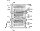
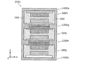
- the battery 2500 includes a current collector 1200 g, a current collector 1200 h, a current collector 1400a, a current collector 1400 b, a power generation element 500 h, a power generation element 500i, and a power generation element 500 j.
- An insulating layer 600a made of an insulating material is formed on the upper surface of the current collector 1400a laminated on the uppermost layer, and an insulating material is formed on the lower surface of the current collector 1400b laminated on the lowermost layer.
- An insulating layer 600b made of the above is formed.
- the current collector 1400a and the current collector 1200h are examples of the first electrode current collector
- the current collector 1200g and the current collector 1400b are examples of the second electrode current collector.
- the electron conductive material and the solid electrolyte are supported on the lower side of the insulating layer 600a, and in the current collector 1400b, the electron conductive material and the solid electrolyte are supported on the upper side of the insulating layer 600b. ..
- the first region 104a of the current collector 1400a and the first region 104b of the current collector 1400b are similar to the first region 100c and the first region 100d shown in FIG. 7A.
- the first region is formed up to the end of the current collector, and current can be taken out from the side end of the current collector.
- the power generation element 500h is arranged in contact with the current collector 1400a and the current collector 1200g, the power generation element 500i is arranged in contact with the current collector 1200g and the current collector 1200h, and the power generation element 500j is arranged.
- the current collector 1200h and the current collector 1400b are arranged in contact with each other.
- the power generation element 500h, the power generation element 500i, and the power generation element 500g each have a laminated structure in which they are laminated so that the stacking order from above is the same.
- the power generation element 500h, the power generation element 500i, and the power generation element 500j are separated by a current collector arranged between them, and each solid electrolyte layer 530 exists independently, and ions do not conduct with each other. Therefore, a bipolar type laminated battery connected in series is constructed.
- an insulating layer is formed on the upper surface of the current collector laminated on the uppermost layer and the lower surface of the current collector laminated on the lowermost layer, and the outer ends of the other current collectors.
- a second insulating region is arranged in the portion. That is, the outer circumference of the battery is made of a material having no electron conductivity except for a place where the first region is formed up to the end of the current collector. Therefore, the possibility of a short circuit is further reduced, and a battery with further improved reliability can be realized.
- the battery 2501 shown in FIG. 11B has a second region 204a of the current collector 1400a, a second region 202g of the current collector 1200g, and a second region 202h of the current collector 1200h in the battery 2500 shown in FIG. 11A.
- the outer periphery of the side surface of the power generation element 500h, the power generation element 500i, and the power generation element 500j in a plan view is covered with the insulating material 260.
- an insulating layer 600a and an insulating layer 600b are formed on the uppermost portion and the lowermost portion of the battery 2500 shown in FIG. 11A. Therefore, the battery 2501 shown in FIG. 11B is entirely covered with an insulating material except for a place where the first region is formed up to the end of the current collector.
- the battery 2501 is the second region 204a of the current collector 1400a, the second region 202g of the current collector 1200g, the second region 202h of the current collector 1200h, and the current collector 1400b in the battery 2500 shown in FIG. 11A. It is manufactured by heat-welding (heat-sealing) the second region 204b.
- the insulating material constituting the insulating layer 600a and the insulating layer 600b is preferably a thermoplastic resin, and is preferably the same kind of material as the insulating material used for the current collector 1200 g and the current collector 1200 h. .. The reason is that there is no difference in melting temperature, stress, etc. at the time of heat welding, and it is unlikely to cause strain, warpage, poor adhesion, or the like.
- thermoplastic resin used as the insulating material has a certain degree of moisture permeability, it is preferable that the battery is further incorporated in a laminate pack, a metal case, or the like.
- the solid electrolyte layer provided in the battery is also arranged on the side surfaces of the positive electrode layer and the negative electrode layer, but the present invention is not limited to this.
- the positive electrode layer, the negative electrode layer, and the solid electrolyte layer may be laminated so as to overlap each other in a plan view.
- the second region and the third region are formed outside each side of the rectangular first region in a plan view, but the present invention is not limited to this.
- the second region and the third region may be formed outside at least one side of the first region, and may be formed only outside the two opposite sides of the first region, for example.
- the battery current collector according to the present disclosure can be used, for example, as a current collector for an all-solid-state lithium secondary battery.
Landscapes
- Chemical & Material Sciences (AREA)
- Engineering & Computer Science (AREA)
- Chemical Kinetics & Catalysis (AREA)
- Electrochemistry (AREA)
- General Chemical & Material Sciences (AREA)
- Materials Engineering (AREA)
- Manufacturing & Machinery (AREA)
- Composite Materials (AREA)
- Physics & Mathematics (AREA)
- Inorganic Chemistry (AREA)
- General Physics & Mathematics (AREA)
- Condensed Matter Physics & Semiconductors (AREA)
- Cell Electrode Carriers And Collectors (AREA)
Priority Applications (3)
| Application Number | Priority Date | Filing Date | Title |
|---|---|---|---|
| CN202080008262.6A CN113302767A (zh) | 2019-03-27 | 2020-01-16 | 电池用集电体、电池、电池用集电体的制造方法和电池的制造方法 |
| JP2021508114A JPWO2020195032A1 (https=) | 2019-03-27 | 2020-01-16 | |
| US17/388,339 US20210359309A1 (en) | 2019-03-27 | 2021-07-29 | Battery current collector, battery, and method for producing battery |
Applications Claiming Priority (2)
| Application Number | Priority Date | Filing Date | Title |
|---|---|---|---|
| JP2019061265 | 2019-03-27 | ||
| JP2019-061265 | 2019-03-27 |
Related Child Applications (1)
| Application Number | Title | Priority Date | Filing Date |
|---|---|---|---|
| US17/388,339 Continuation US20210359309A1 (en) | 2019-03-27 | 2021-07-29 | Battery current collector, battery, and method for producing battery |
Publications (1)
| Publication Number | Publication Date |
|---|---|
| WO2020195032A1 true WO2020195032A1 (ja) | 2020-10-01 |
Family
ID=72610419
Family Applications (1)
| Application Number | Title | Priority Date | Filing Date |
|---|---|---|---|
| PCT/JP2020/001202 Ceased WO2020195032A1 (ja) | 2019-03-27 | 2020-01-16 | 電池用集電体、電池、電池用集電体の製造方法、および、電池の製造方法 |
Country Status (4)
| Country | Link |
|---|---|
| US (1) | US20210359309A1 (https=) |
| JP (1) | JPWO2020195032A1 (https=) |
| CN (1) | CN113302767A (https=) |
| WO (1) | WO2020195032A1 (https=) |
Cited By (3)
| Publication number | Priority date | Publication date | Assignee | Title |
|---|---|---|---|---|
| WO2022176318A1 (ja) * | 2021-02-19 | 2022-08-25 | パナソニックIpマネジメント株式会社 | 電池 |
| WO2022270141A1 (ja) * | 2021-06-24 | 2022-12-29 | パナソニックIpマネジメント株式会社 | 電池及び電池の製造方法 |
| CN115939504A (zh) * | 2021-08-13 | 2023-04-07 | 通用汽车环球科技运作有限责任公司 | 用于固态电池组的凝胶电解质体系 |
Families Citing this family (3)
| Publication number | Priority date | Publication date | Assignee | Title |
|---|---|---|---|---|
| CN114388883B (zh) * | 2020-10-16 | 2024-12-20 | 通用汽车环球科技运作有限责任公司 | 包含离子凝胶的固态双极型电池组 |
| CN114843519A (zh) * | 2022-05-26 | 2022-08-02 | 东莞锂威能源科技有限公司 | 集流体、正极片、负极片、叠片电芯、电池及制备方法 |
| KR20250158565A (ko) * | 2024-04-30 | 2025-11-06 | 삼성에스디아이 주식회사 | 전고체 이차 전지 |
Citations (4)
| Publication number | Priority date | Publication date | Assignee | Title |
|---|---|---|---|---|
| JP2004014151A (ja) * | 2002-06-03 | 2004-01-15 | Sony Corp | 電池 |
| JP2010073500A (ja) * | 2008-09-18 | 2010-04-02 | Nissan Motor Co Ltd | 有機構造体を含む双極型リチウムイオン二次電池用集電体 |
| WO2011033702A1 (ja) * | 2009-09-17 | 2011-03-24 | 株式会社村田製作所 | 電池間分離構造体とそれを備えた積層型固体二次電池 |
| JP2017208250A (ja) * | 2016-05-19 | 2017-11-24 | マクセルホールディングス株式会社 | 全固体リチウム二次電池及びその製造方法 |
Family Cites Families (6)
| Publication number | Priority date | Publication date | Assignee | Title |
|---|---|---|---|---|
| JP2011192540A (ja) * | 2010-03-15 | 2011-09-29 | Nissan Motor Co Ltd | 双極型二次電池 |
| FR2961637B1 (fr) * | 2010-06-16 | 2012-07-27 | Commissariat Energie Atomique | Collecteur de courant avec moyens d'etancheite integres, batterie bipolaire comprenant un tel collecteur |
| JP5888730B2 (ja) * | 2012-01-27 | 2016-03-22 | 三洋電機株式会社 | 角形二次電池 |
| FR2996360B1 (fr) * | 2012-10-01 | 2014-10-17 | Commissariat Energie Atomique | Collecteur de courant avec moyens d'etancheite integres, batterie bipolaire comprenant un tel collecteur, procede de realisation d'une telle batterie. |
| JP2018055898A (ja) * | 2016-09-28 | 2018-04-05 | 株式会社日立製作所 | 全固体電池 |
| CN109935783B (zh) * | 2019-02-21 | 2021-02-19 | 宁德新能源科技有限公司 | 电化学装置和电子装置 |
-
2020
- 2020-01-16 JP JP2021508114A patent/JPWO2020195032A1/ja not_active Withdrawn
- 2020-01-16 CN CN202080008262.6A patent/CN113302767A/zh active Pending
- 2020-01-16 WO PCT/JP2020/001202 patent/WO2020195032A1/ja not_active Ceased
-
2021
- 2021-07-29 US US17/388,339 patent/US20210359309A1/en not_active Abandoned
Patent Citations (4)
| Publication number | Priority date | Publication date | Assignee | Title |
|---|---|---|---|---|
| JP2004014151A (ja) * | 2002-06-03 | 2004-01-15 | Sony Corp | 電池 |
| JP2010073500A (ja) * | 2008-09-18 | 2010-04-02 | Nissan Motor Co Ltd | 有機構造体を含む双極型リチウムイオン二次電池用集電体 |
| WO2011033702A1 (ja) * | 2009-09-17 | 2011-03-24 | 株式会社村田製作所 | 電池間分離構造体とそれを備えた積層型固体二次電池 |
| JP2017208250A (ja) * | 2016-05-19 | 2017-11-24 | マクセルホールディングス株式会社 | 全固体リチウム二次電池及びその製造方法 |
Cited By (8)
| Publication number | Priority date | Publication date | Assignee | Title |
|---|---|---|---|---|
| WO2022176318A1 (ja) * | 2021-02-19 | 2022-08-25 | パナソニックIpマネジメント株式会社 | 電池 |
| JPWO2022176318A1 (https=) * | 2021-02-19 | 2022-08-25 | ||
| JP7801688B2 (ja) | 2021-02-19 | 2026-01-19 | パナソニックIpマネジメント株式会社 | 電池 |
| WO2022270141A1 (ja) * | 2021-06-24 | 2022-12-29 | パナソニックIpマネジメント株式会社 | 電池及び電池の製造方法 |
| JPWO2022270141A1 (https=) * | 2021-06-24 | 2022-12-29 | ||
| JP7833689B2 (ja) | 2021-06-24 | 2026-03-23 | パナソニックIpマネジメント株式会社 | 電池及び電池の製造方法 |
| CN115939504A (zh) * | 2021-08-13 | 2023-04-07 | 通用汽车环球科技运作有限责任公司 | 用于固态电池组的凝胶电解质体系 |
| US12412928B2 (en) | 2021-08-13 | 2025-09-09 | GM Global Technology Operations LLC | Gel electrolyte system for solid state battery |
Also Published As
| Publication number | Publication date |
|---|---|
| CN113302767A (zh) | 2021-08-24 |
| JPWO2020195032A1 (https=) | 2020-10-01 |
| US20210359309A1 (en) | 2021-11-18 |
Similar Documents
| Publication | Publication Date | Title |
|---|---|---|
| WO2020195032A1 (ja) | 電池用集電体、電池、電池用集電体の製造方法、および、電池の製造方法 | |
| JP6493057B2 (ja) | 金属空気電池の負極複合体及び金属空気電池 | |
| CN104170151B (zh) | 电极组件的制造方法及包括由该方法制造的电极组件的电化学元件 | |
| CN104584307B (zh) | 电极组件及其制造方法 | |
| JP5233435B2 (ja) | 双極型二次電池 | |
| JP2018181451A (ja) | 積層型全固体電池およびその製造方法 | |
| CN110416630A (zh) | 全固体电池 | |
| CN103069614A (zh) | 具有内置的密封装置的集电体、和包括这种集电体的双极电池 | |
| JP2019207840A (ja) | 全固体電池 | |
| JP7437710B2 (ja) | 積層電池 | |
| WO2018092640A1 (ja) | 高出力電池および電池ケース | |
| CN108695556A (zh) | 层叠电池 | |
| JP2004047239A (ja) | 薄型電池、組電池、複合組電池及びそれを搭載した車両 | |
| JP2020095871A (ja) | 積層型電池および積層型電池の製造方法 | |
| JP2017152247A (ja) | 全固体型電極体及び電気化学セル | |
| JP2005251617A (ja) | 二次電池及び組電池 | |
| CN110635175A (zh) | 一种内部串联式电芯和内部串联式电池 | |
| CN108335915B (zh) | 电极组件的制造方法及包括该电极组件的电化学电池 | |
| JP2017152284A (ja) | 袋状セパレータ及び非水電解質二次電池 | |
| JP2019197677A (ja) | 積層型電池 | |
| JP7238757B2 (ja) | 全固体電池 | |
| JP6832477B2 (ja) | 積層型電池および積層型電池の製造方法 | |
| JP2020170667A (ja) | 積層型電池の製造方法および積層型電池 | |
| JP2019220333A (ja) | 積層型電池及び積層型電池の製造方法 | |
| JP2019207746A (ja) | 積層型電池用電極及び積層型電池 |
Legal Events
| Date | Code | Title | Description |
|---|---|---|---|
| 121 | Ep: the epo has been informed by wipo that ep was designated in this application |
Ref document number: 20778030 Country of ref document: EP Kind code of ref document: A1 |
|
| ENP | Entry into the national phase |
Ref document number: 2021508114 Country of ref document: JP Kind code of ref document: A |
|
| NENP | Non-entry into the national phase |
Ref country code: DE |
|
| 122 | Ep: pct application non-entry in european phase |
Ref document number: 20778030 Country of ref document: EP Kind code of ref document: A1 |