WO2020189614A1 - 液体タンク - Google Patents
液体タンク Download PDFInfo
- Publication number
- WO2020189614A1 WO2020189614A1 PCT/JP2020/011382 JP2020011382W WO2020189614A1 WO 2020189614 A1 WO2020189614 A1 WO 2020189614A1 JP 2020011382 W JP2020011382 W JP 2020011382W WO 2020189614 A1 WO2020189614 A1 WO 2020189614A1
- Authority
- WO
- WIPO (PCT)
- Prior art keywords
- tank body
- tank
- opening
- fuel
- pipe
- Prior art date
- Legal status (The legal status is an assumption and is not a legal conclusion. Google has not performed a legal analysis and makes no representation as to the accuracy of the status listed.)
- Ceased
Links
Images




Classifications
-
- B—PERFORMING OPERATIONS; TRANSPORTING
- B60—VEHICLES IN GENERAL
- B60K—ARRANGEMENT OR MOUNTING OF PROPULSION UNITS OR OF TRANSMISSIONS IN VEHICLES; ARRANGEMENT OR MOUNTING OF PLURAL DIVERSE PRIME-MOVERS IN VEHICLES; AUXILIARY DRIVES FOR VEHICLES; INSTRUMENTATION OR DASHBOARDS FOR VEHICLES; ARRANGEMENTS IN CONNECTION WITH COOLING, AIR INTAKE, GAS EXHAUST OR FUEL SUPPLY OF PROPULSION UNITS IN VEHICLES
- B60K15/00—Arrangement in connection with fuel supply of combustion engines or other fuel consuming energy converters, e.g. fuel cells; Mounting or construction of fuel tanks
- B60K15/03—Fuel tanks
- B60K15/035—Fuel tanks characterised by venting means
-
- F—MECHANICAL ENGINEERING; LIGHTING; HEATING; WEAPONS; BLASTING
- F02—COMBUSTION ENGINES; HOT-GAS OR COMBUSTION-PRODUCT ENGINE PLANTS
- F02M—SUPPLYING COMBUSTION ENGINES IN GENERAL WITH COMBUSTIBLE MIXTURES OR CONSTITUENTS THEREOF
- F02M37/00—Apparatus or systems for feeding liquid fuel from storage containers to carburettors or fuel-injection apparatus; Arrangements for purifying liquid fuel specially adapted for, or arranged on, internal-combustion engines
Definitions
- the present disclosure relates to a liquid tank, and more particularly to a liquid tank suitable for storing a liquid such as a fuel for an internal combustion engine in a vehicle.
- the fuel of an internal combustion engine which is a liquid
- the fuel tank includes a tank body which is a container for substantially storing fuel, a filler pipe for injecting a liquid into the tank body, and a breather pipe for discharging gas in the tank body when the liquid is injected. ..
- the outlet of the breather pipe is connected to the inlet of the filler pipe, and the gas through the breather pipe is released to the atmosphere from the outlet of the breather pipe via the inlet of the filler pipe.
- this disclosure was devised in view of such circumstances, and the purpose is to provide a liquid tank capable of suppressing the liquid from being ejected from the inlet of the filler pipe.
- a filler pipe connected to the tank body and for injecting a liquid into the tank body
- a breather pipe connected to the tank body and the filler pipe for discharging gas in the tank body when a liquid is injected.
- the breather pipe includes an inlet portion arranged downward in the tank body and an opening provided on a peripheral side surface portion of the inlet portion.
- a liquid tank is provided, characterized in that the cross-sectional area of the opening decreases upward.
- the cross-sectional area of the opening is continuously reduced toward the upper side.
- the opening is a triangle having a base at the lower end of the entrance.
- FIG. 1 is a schematic view showing a part of the fuel tank according to the embodiment of the present disclosure.
- FIG. 2 is an enlarged view showing a main part of the fuel tank.
- FIG. 3 is a diagram showing a decrease in the cross-sectional area of the opening.
- FIG. 4A is a diagram showing a decrease in the cross-sectional area of the opening.
- FIG. 4B is a diagram showing a decrease in the cross-sectional area of the opening.
- FIG. 4C is a diagram showing a decrease in the cross-sectional area of the opening.
- FIG. 5 is a diagram showing a first modification.
- FIG. 6 is a diagram showing a second modification.
- FIG. 1 is a schematic view showing a part of the liquid tank according to the present embodiment.
- the liquid tank of the present embodiment is applied as a fuel tank 1 for storing fuel of an internal combustion engine (engine) in a vehicle, and the liquid to be stored is fuel.
- the vehicle is a large vehicle such as a truck
- the internal combustion engine is a diesel engine
- the fuel is light oil.
- the type, application, etc. of the vehicle, internal combustion engine, and fuel are not particularly limited.
- the vehicle may be a small vehicle such as a passenger car
- the engine may be a gasoline engine
- the fuel may be gasoline. You may.
- the engine may be mounted on a moving body other than a vehicle, for example, a ship, a construction machine, or an industrial machine. Further, the engine does not have to be mounted on a moving body, and may be a stationary engine.
- the fuel tank 1 is connected to a tank body 2 which is a container for substantially storing fuel (not shown), a filler pipe 3 which is connected to the tank body 2 and for injecting fuel into the tank body 2, and a tank body 2. And a breather pipe 4 connected to the filler pipe 3 and for discharging the gas in the tank body 2 at the time of fuel injection.
- the tank body 2 of this embodiment is made of resin.
- the material is arbitrary and may be made of metal.
- the filler pipe 3 has an outlet portion 5 as one end portion inserted and fixed to the tank body 2 from the side, and extends upward (obliquely upward in the illustrated example) from the outlet portion 5. Further, the filler pipe 3 has an inlet portion 6 as the other end portion located above the outlet portion 5.
- the filler pipe 3 is supplied with fuel from the refueling nozzle Z inserted into the inlet portion 6 from the outside, guides the supplied fuel and discharges the supplied fuel into the tank body 2 from the outlet portion 5, and discharges the fuel into the tank body 2. Inject into 2.
- the filler pipe 3 is capable of efficiently injecting fuel by utilizing the head between the inlet portion 6 and the outlet portion 5.
- a tapered nozzle insertion pipe 7 is provided inside the inlet portion 6 of the filler pipe 3 to insert and position the refueling nozzle Z and prevent fuel from blowing back as much as possible.
- a filler cap 8 is detachably attached to the inlet portion 6 of the filler pipe 3.
- the breather pipe 4 has an inlet portion 9 as one end portion inserted and fixed to the tank body 2 from above, and extends upward (obliquely upward in the illustrated example) from the inlet portion 9. Further, the breather pipe 4 has an outlet portion 10 as the other end portion located above the inlet portion 9. The outlet portion 10 is connected to the inlet portion 6 of the filler pipe 3 on the outer peripheral side of the nozzle insertion pipe 7.
- the breather pipe 4 has a smaller diameter than the filler pipe 3 and has a circular cross section. For example, the inner diameter of the filler pipe 3 is about 30 to 40 mm, and the inner diameter of the breather pipe 4 is about 12 mm.
- the breather pipe 4 is sometimes referred to as a breather tube, a vent pipe, a vent tube, or the like.
- FIG. 2 shows in detail the main parts of the fuel tank 1.
- the breather pipe 4 is divided into three parts in the longitudinal direction, and the inlet portion 9 formed of the L-shaped pipe, the outlet portion 10 formed of the same L-shaped pipe, and these inlet portions 6 It also has an intermediate portion 11 that connects the outlet portion 10.
- the intermediate portion 11 is formed by a flexible hose.
- the inlet end portion of the intermediate portion 11 is closely fitted to the outside of the inlet portion 9, and is tightened and fixed from the outer peripheral side by the fastening band 12.
- the outlet end portion of the intermediate portion 11 is closely fitted to the outside of the outlet portion 10, and is tightened and fixed from the outer peripheral side by the fastening band 12.
- Other methods are also possible for connecting the intermediate portion 11. For example, when connecting the intermediate portion 11 to the inlet portion 9, a connection method using a quick connector or a connection method by press fitting can also be adopted.
- the entrance portion 9 has a vertical portion 13 located on the inlet side thereof and extending in the vertical direction, and a horizontal portion 14 located on the exit side thereof and curved from the upper end of the vertical portion 13 and extending in the horizontal direction or the horizontal direction.
- the lateral portion 14 is located outside the tank body 2, and the inlet end portion of the intermediate portion 11 is connected.
- An insertion hole 15 is provided in the upper surface portion 2A of the tank body 2, and the vertical portion 13 of the inlet portion 9 is inserted into the insertion hole 15 from above.
- a mounting flange 16 is fixed to the outer peripheral portion of the vertical portion 13, and the mounting flange 16 is fixed to the upper surface portion 2A of the tank body 2 so that the inlet portion 9 is fixed to the tank body 2.
- the inlet portion 9 and the mounting flange 16 are made of the same resin as the tank body 2.
- the mounting flange 16 has a shape like an inverted ring plate, and is integrally molded on the outer peripheral portion of the vertical portion 13. Further, the lower end surface 17 of the mounting flange 16 is integrally fixed to the upper surface portion 2A of the tank body 2 by heat welding or the like. As a result, the inlet portion 9 is fixed to the tank body 2 while preventing fuel leakage and gas leakage from the tank body 2.
- the mounting flange 16 is welded to the inlet 9 and the tank body 2.
- the inlet portion 9 When the inlet portion 9 is fixed in this way, the lower half portion of the vertical portion 13 is arranged downward in the tank body 2. That is, the inlet portion 9 is arranged in the tank main body 2 with the circular inlet opening 19 (see FIG. 3) located at the lower end 18 thereof facing downward. As shown in FIG. 1, the height position H2 of the lower end 18 to the inlet opening 19 is higher than the height position H1 of the upper end of the outlet opening 20 of the filler pipe 3. The lower end 18 is perpendicular to the axial direction of the vertical portion 13.
- an opening 22 is provided in the peripheral side surface portion 21 of the vertical portion 13 arranged in the tank body 2.
- the cross-sectional area of the opening 22 decreases toward the upper side, and particularly continuously decreases in the present embodiment.
- the opening 22 is a triangle having a base at the position of the lower end 18 of the vertical portion 13, particularly an isosceles triangle, and extends upward from the position of the lower end 18 of the vertical portion 13.
- the opening 22 has a shape such that the peripheral side surface portion 21 is cut out upward from the lower end 18 of the vertical portion 13, and communicates with the entrance opening 19 at the position of the lower end 18.
- the opening 22 has a predetermined apex angle ⁇ and a pair of hypotenuses 24 extending obliquely upward from the lower end 18 and intersecting at the apex 23.
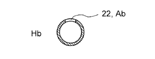
- FIGS. 4A to 4C show a cross section (cross section) of the vertical portion 13 at each height position Ha, Hb, Hc that increases in order from the bottom.
- the highest height position Hc is the height position near the top 23, and Hb is the height position in between. Note that FIG. 4C shows a state when the lower end 18 is viewed from below.
- the cross-sectional area of the opening 22 means, for example, in the case of FIGS. 4A to 4C, the areas Aa, Ab, and Ac of the portion representing the opening 22. As can be seen from this figure, the cross-sectional area of the opening 22 is continuously reduced toward the upper side. Further, the width W of the opening 22 is also continuously reduced toward the upper side.
- the rate at which the cross-sectional area of the opening 22 decreases with respect to the height from the lower end 18, that is, the cross-sectional area reduction rate can be changed according to the size of the apex angle ⁇ . For example, if the apex angle ⁇ is increased, the cross-section reduction rate can be increased, and conversely, if the apex angle ⁇ is decreased, the cross-section reduction rate can be reduced.
- this comparative example has the following problems.
- the refueling nozzle Z of the refueling gun is inserted into the nozzle insertion pipe 7 at the inlet 6 of the filler pipe 3 to start refueling.
- the liquid level in the tank body 2 gradually rises, and eventually the liquid level reaches the height position H1 at the upper end of the outlet opening 20 of the filler pipe 3. In that case, the outlet opening 20 of the filler pipe 3 is closed with fuel. After that, the liquid level rises in the tank body 2 and in the filler pipe 3. At this time, the gas (referred to as the gas in the tank) in the space above the liquid level (referred to as the space in the tank) in the tank body 2 is released to the atmosphere through the breather pipe 4.
- the gas in the tank is a mixture of air and fuel vapor.
- the gas in the tank is pushed into the breather pipe 4 from the inlet 9 of the breather pipe 4 due to the rise in the liquid level.
- the gas in the tank flows through the gap between the nozzle insertion pipe 7 and the refueling nozzle Z in the reverse flow direction opposite to the refueling direction, and is discharged from the inlet portion 6 of the filler pipe 3 to the atmosphere.
- the liquid level reaches the height position H2 of the lower end 18 of the inlet portion 9 of the breather pipe 4. In that case, the inlet opening 19 of the breather pipe 4 is closed with fuel.
- the flow rate of the fuel supplied to the filler pipe 3 is sufficiently small (that is, the refueling speed is sufficiently slow).
- the rise of the liquid level in the tank body 2 stops. Instead, the fuel penetrates into the breather pipe 4 through the inlet opening 19 and the liquid level rises in the filler pipe 3 and in the breather pipe 4.
- the gas in the tank above the liquid level is pushed upward and released to the atmosphere.
- the flow rate of the fuel supplied to the filler pipe 3 is large (that is, the refueling speed is high)
- the rise in the liquid level in the tank body 2 should stop, but the fuel flow rate is high. Therefore, the liquid level rises slightly, the gas in the tank in the tank body 2 is compressed, and the pressure of the gas in the tank rises sharply.
- the gas in the tank rapidly pushes the fuel in the tank body 2 into the breather pipe 4.
- the extruded fuel soars in the breather pipe 4, and is ejected from the inlet portion 6 of the filler pipe 3 to the outside at substantially the same timing as, for example, when the refueling is automatically stopped.
- the fuel that has risen sharply in the breather pipe 4 is discharged from the outlet portion 10 into the inlet portion 6 of the filler pipe 3, and then in the nozzle insertion pipe 7 and the refueling nozzle Z, as in the above-mentioned gas discharge path. Through the gap, it flows in the reverse flow direction opposite to the refueling direction, and is ejected from the inlet portion 6 of the filler pipe 3 to the outside.
- this fuel ejection occurs when (i) the breather pipe 4 has a smaller diameter than the filler pipe 3 and the fuel rising speed tends to increase, and (ii) the filler pipe 3 becomes long or has a complicated shape due to the vehicle layout. Another cause is that the fuel rising speed in the filler pipe 3 is difficult to increase.
- an opening 22 is provided at the inlet 9 of the breather pipe 4.
- the following effects can be obtained. It is assumed that the flow rate of the fuel supplied to the filler pipe 3 is large.
- the cross-sectional area of the opening 22 is reduced toward the upper side. In this way, as the liquid level rises from the height position H2, the area of the substantial opening 22 that communicates the space inside the tank with the inside of the breather pipe 4 can be reduced. Then, it is possible to make it difficult for the gas in the tank to escape as the liquid level rises, and to make it easier to raise the pressure of the gas in the tank. As a result, it becomes possible to realize the planned fuel rise in the filler pipe 3 and automatic refueling stop.
- the opening 22 whose cross-sectional area decreases toward the upper side is provided, at the same time when the liquid level reaches the height position H2, the space inside the tank and the inside of the breather pipe 4 are communicated with each other.
- the communication area can be gradually reduced as the liquid level rises from the height position H2, rather than immediately shutting off.
- the pressure rise of the gas in the tank after the liquid level reaches the high position H2 can be suppressed, and the fuel is ejected from the inlet portion 6 of the filler pipe 3 even when the refueling speed is high. Refueling can be reliably and automatically stopped. Therefore, it is possible to prevent the fuel from being ejected from the inlet portion 6 of the filler pipe 3.
- the shape of the opening 22 is changed to a right triangle.
- the opening 22 is a right triangle having a base at the position of the lower end 18 of the vertical portion 13, and extends upward from the position of the lower end 18 of the vertical portion 13.
- the opening 22 has a predetermined apex angle ⁇ , a apex 23, a vertical side 26 extending vertically upward from the lower end 18, and a hypotenuse 27 intersecting the vertical side 26 at the apex 23.
- the opening 22 is formed by a plurality of holes 28 instead of notches. And the number of holes 28 decreases toward the top. Therefore, the cross-sectional area of the opening 22 of this modification is reduced toward the upper side, and in particular, it is generally gradually reduced. Even with such a modified example, it is possible to exert substantially the same effect as that of the basic embodiment.
- the cross-sectional area of the opening 22 as used herein means the total area of one or more holes 28 in a specific cross section.
- holes 28 are arranged side by side in a row at the bottom.
- the number of holes 28 is reduced one by one as the row goes up.
- the number of holes 28 in the uppermost stage is one, and the total number of stages is five.
- the holes 28 are circular and are arranged in a staggered pattern. The dimensions of the holes 28 are all the same.
- the present disclosure is applicable to a liquid tank other than a fuel tank, which stores a liquid other than fuel.
- a liquid tank other than a fuel tank, which stores a liquid other than fuel.
- some vehicles equipped with a diesel engine are equipped with an SCR (Selective Catalyst Reduction) device for reducing and purifying NOx in the exhaust.
- Liquid urea water is used as a reducing agent in the SCR device, and a urea water tank for storing the urea water is mounted on the vehicle.
- the urea water is injected into the urea water tank, the same urea water as described above may be ejected.
- the present disclosure can be applied to the urea water tank to suppress the ejection of urea water.
- the shape of the opening may be a shape other than a triangle, for example, a semicircle, as long as the cross-sectional area decreases toward the upper side.
- the exhaust gas purification device and the control device of the exhaust gas purification device according to the present disclosure can suppress the occurrence of clogging of the filter while saving the power consumption of the heater.
Landscapes
- Engineering & Computer Science (AREA)
- Chemical & Material Sciences (AREA)
- Combustion & Propulsion (AREA)
- Mechanical Engineering (AREA)
- General Engineering & Computer Science (AREA)
- Life Sciences & Earth Sciences (AREA)
- Sustainable Development (AREA)
- Sustainable Energy (AREA)
- Transportation (AREA)
- Cooling, Air Intake And Gas Exhaust, And Fuel Tank Arrangements In Propulsion Units (AREA)
Abstract
液体タンク1は、タンク本体2と、タンク本体に接続され、タンク本体に液体を注入するためのフィラーパイプ3と、タンク本体およびフィラーパイプに接続され、液体の注入時にタンク本体内のガスを排出するためのブリーザパイプ4とを備える。ブリーザパイプは、タンク本体内に下向きに配置された入口部9と、入口部の周側面部21に設けられた開口部22とを備える。開口部の断面積は、上方に向かうほど減少される。
Description
本開示は液体タンクに係り、特に、車両における内燃機関の燃料等の液体を貯留するのに適した液体タンクに関する。
例えば車両では、液体である内燃機関の燃料を、液体タンクとしての燃料タンクに貯留する。燃料タンクは、燃料を実質的に貯留する容器であるタンク本体と、タンク本体に液体を注入するためのフィラーパイプと、液体の注入時にタンク本体内のガスを排出するためのブリーザパイプとを備える。
ブリーザパイプの出口部はフィラーパイプの入口部に接続され、ブリーザパイプを通じたガスが、ブリーザパイプの出口部からフィラーパイプの入口部を経由して大気に開放されるようになっている。
ここで、給油時にフィラーパイプに供給される燃料の流量が少ない場合には特に問題がない。しかし、その流量が多いと、タンク本体内のガスの圧力が上昇し、タンク本体内の燃料がブリーザパイプ内に押し出されてしまう。そしてその燃料が、ブリーザパイプの出口部から排出された後にフィラーパイプ内を逆流し、フィラーパイプの入口部から外部に噴き出してしまうという問題がある。
そこで本開示は、かかる事情に鑑みて創案され、その目的は、フィラーパイプの入口部から液体が噴き出すことを抑制できる液体タンクを提供することにある。
本開示の一の態様によれば、
タンク本体と、
前記タンク本体に接続され、前記タンク本体に液体を注入するためのフィラーパイプと、
前記タンク本体および前記フィラーパイプに接続され、液体の注入時に前記タンク本体内のガスを排出するためのブリーザパイプと、
を備え、
前記ブリーザパイプは、前記タンク本体内に下向きに配置された入口部と、前記入口部の周側面部に設けられた開口部とを備え、
前記開口部の断面積は、上方に向かうほど減少される
ことを特徴とする液体タンクが提供される。
タンク本体と、
前記タンク本体に接続され、前記タンク本体に液体を注入するためのフィラーパイプと、
前記タンク本体および前記フィラーパイプに接続され、液体の注入時に前記タンク本体内のガスを排出するためのブリーザパイプと、
を備え、
前記ブリーザパイプは、前記タンク本体内に下向きに配置された入口部と、前記入口部の周側面部に設けられた開口部とを備え、
前記開口部の断面積は、上方に向かうほど減少される
ことを特徴とする液体タンクが提供される。
好ましくは、前記開口部の断面積は、上方に向かうほど連続的に減少される。
好ましくは、前記開口部は、前記入口部の下端の位置に底辺を有する三角形とされる。
本開示によれば、フィラーパイプの入口から液体が噴き出すことを抑制できる。
以下、添付図面を参照して本開示の実施形態を説明する。なお本開示は以下の実施形態に限定されない点に留意されたい。
図1は、本実施形態に係る液体タンクの一部を示す概略図である。本実施形態の液体タンクは、車両において内燃機関(エンジン)の燃料を貯留する燃料タンク1として適用され、貯留対象の液体は燃料である。車両はトラック等の大型車両であり、内燃機関はディーゼルエンジンであり、燃料は軽油である。しかしながら、車両、内燃機関および燃料の種類、用途等に特に限定はなく、例えば車両は乗用車等の小型車両であってもよいし、エンジンはガソリンエンジンであってもよいし、燃料はガソリンであってもよい。
なおエンジンは、車両以外の移動体、例えば船舶、建設機械、または産業機械に搭載されたものであってもよい。またエンジンは、移動体に搭載されたものでなくてもよく、定置式のものであってもよい。
燃料タンク1は、燃料(図示せず)を実質的に貯留する容器であるタンク本体2と、タンク本体2に接続され、タンク本体2に燃料を注入するためのフィラーパイプ3と、タンク本体2およびフィラーパイプ3に接続され、燃料の注入時にタンク本体2内のガスを排出するためのブリーザパイプ4とを備える。
本実施形態のタンク本体2は樹脂製とされている。但し材質は任意であり、金属製とされても構わない。
フィラーパイプ3は、タンク本体2に側方から挿入され固定された一端部としての出口部5を有し、この出口部5から上方(図示例では斜め上方)に向かって延びている。またフィラーパイプ3は、出口部5よりも上方に位置された他端部としての入口部6を有する。フィラーパイプ3は、外部から入口部6に差し込まれた給油ノズルZから燃料を供給されると共に、その供給された燃料を案内して出口部5からタンク本体2内に排出し、燃料をタンク本体2内に注入する。フィラーパイプ3は、入口部6と出口部5の落差を利用して効率的に燃料を注入できるようになっている。
任意ではあるが、フィラーパイプ3の入口部6の内側には、給油ノズルZを挿入させて位置決めすると共に燃料の吹き返しを極力防止するテーパ状のノズル挿入管7が設けられる。またフィラーパイプ3の入口部6にはフィラーキャップ8が着脱可能に取り付けられる。
ブリーザパイプ4は、タンク本体2に上方から挿入され固定された一端部としての入口部9を有し、この入口部9から上方(図示例では斜め上方)に向かって延びている。またブリーザパイプ4は、入口部9よりも上方に位置された他端部としての出口部10を有する。出口部10は、ノズル挿入管7の外周側にて、フィラーパイプ3の入口部6に接続されている。ブリーザパイプ4はフィラーパイプ3より小径で断面円形のパイプとされる。例えばフィラーパイプ3の内径は30~40mm程度、ブリーザパイプ4の内径は12mm程度である。
なおブリーザパイプ4は、ブリーザチューブ、ベントパイプまたはベントチューブ等と称されることもある。
図2に、燃料タンク1の要部を詳細に示す。図示するようにブリーザパイプ4は、長手方向に三分割の構成とされ、L字状パイプにより形成された入口部9と、同じくL字状パイプにより形成された出口部10と、これら入口部6および出口部10を連結する中間部11とを有する。
中間部11は柔軟なホースにより形成される。中間部11の入口端部は入口部9の外側に密着嵌合され、締結バンド12で外周側から締め付けられ固定される。同様に、中間部11の出口端部は出口部10の外側に密着嵌合され、締結バンド12で外周側から締め付けられ固定される。なお中間部11の接続方法は他の方法も可能である。例えば入口部9に中間部11を接続する場合、クイックコネクタを使った接続方法や、圧入による接続方法も採用できる。
入口部9は、その入口側に位置され鉛直方向に延びる縦部13と、その出口側に位置され縦部13上端から湾曲して横方向もしくは水平方向に延びる横部14とを有する。横部14はタンク本体2の外部に位置され、中間部11の入口端部が接続される。
タンク本体2の上面部2Aに挿通穴15が設けられ、この挿通穴15に入口部9の縦部13が上方から挿通される。縦部13の外周部には取付フランジ16が固定され、この取付フランジ16がタンク本体2の上面部2Aに固定されることで、入口部9がタンク本体2に固定される。
本実施形態では、入口部9と取付フランジ16がタンク本体2と同様の樹脂製とされている。取付フランジ16は、上下反転した円環皿のような形状とされ、縦部13の外周部に一体成形されている。また、取付フランジ16の下端面17は、タンク本体2の上面部2Aに熱溶着等により一体的に固定される。これにより、タンク本体2からの燃料漏れおよびガス漏れを防止しつつ入口部9がタンク本体2に固定される。
なお、タンク本体2と入口部9と取付フランジ16が金属製の場合だと、取付フランジ16は入口部9とタンク本体2に溶接される。
このように入口部9が固定されると、縦部13の下半部は、タンク本体2内に下向きに配置される。すなわち、入口部9は、その下端18に位置する円形の入口開口19(図3参照)を下に向けた状態で、タンク本体2内に配置される。この下端18ないし入口開口19の高さ位置H2は、図1に示すように、フィラーパイプ3の出口開口20の上端の高さ位置H1より高い。なお下端18は縦部13の軸方向に垂直である。
加えて本実施形態では、タンク本体2内に配置された縦部13の周側面部21に開口部22が設けられている。開口部22の断面積は、上方に向かうほど減少され、特に本実施形態では連続的に減少される。
本実施形態において開口部22は、縦部13の下端18の位置に底辺を有する三角形、特に二等辺三角形とされ、縦部13の下端18の位置から上方に向かって延びている。開口部22は、縦部13の下端18から上方に向かって周側面部21を切り欠いたような形状となっており、下端18の位置で入口開口19と連通する。開口部22は、所定の頂角θと、下端18から斜め上方に延びて頂部23で交わる一対の斜辺部24とを有する。
図4A~図4Cには、下方から順に高くなる各高さ位置Ha,Hb,Hcでの縦部13の断面(横断面)を示す。最も低い高さ位置Haは下端18での高さ位置である(Ha=H2)。最も高い高さ位置Hcは頂部23付近の高さ位置であり、Hbはそれらの中間の高さ位置である。なお図4Cは下端18を下方から見たときの様子を表す。
開口部22の断面積とは、例えば図4A~図4Cの場合、開口部22を表す部分の面積Aa,Ab,Acを意味する。この図から分かるように、開口部22の断面積は上方に向かうほど連続的に減少される。また開口部22の幅Wも、上方に向かうほど連続的に減少される。
下端18からの高さに対して開口部22の断面積が減少する割合、すなわち断面積減少率を、頂角θの大きさに応じて変えることができる。例えば頂角θを大きくすれば断面積減少率を大きくすることができ、逆に頂角θを小さくすれば断面積減少率を小さくすることができる。
さて、仮に開口部22がない比較例を想定した場合、この比較例には次のような問題がある。
図1に示すように、例えば空の燃料タンク1に満タンまで給油する場合、フィラーパイプ3の入口部6におけるノズル挿入管7に給油ガンの給油ノズルZを差し込み、給油を開始する。
タンク本体2内の液面レベルは次第に上昇し、やがて液面レベルは、フィラーパイプ3の出口開口20の上端の高さ位置H1に達する。そうなるとフィラーパイプ3の出口開口20が燃料で塞がれる。この後、タンク本体2内とフィラーパイプ3内とで、液面レベルが上昇する。このとき、タンク本体2内で液面の上方の空間(タンク内空間という)にあるガス(タンク内ガスという)は、ブリーザパイプ4を通じて大気に開放される。ここでタンク内ガスは、空気と燃料蒸気との混合気である。
詳しくは、液面レベルの上昇によりタンク内ガスが、ブリーザパイプ4の入口部9からブリーザパイプ4内に押し込まれる。この押し込まれたタンク内ガスは、ブリーザパイプ4内を上昇し、その出口部10からフィラーパイプ3の入口部6内に排出される。そしてそのタンク内ガスは、ノズル挿入管7と給油ノズルZの隙間を通じて、給油方向とは逆の逆流方向に流れ、フィラーパイプ3の入口部6から大気へと排出される。
その後、液面レベルは、図2にも示すように、ブリーザパイプ4の入口部9の下端18の高さ位置H2に達する。そうなると、ブリーザパイプ4の入口開口19が燃料で塞がれる。
ここで、フィラーパイプ3に供給される燃料の流量は十分に少ない(すなわち給油速度は十分に遅い)と仮定する。この場合、ブリーザパイプ4の入口開口19が燃料で塞がれてからは、タンク本体2内の液面レベルの上昇が停止する。代わりに、燃料は入口開口19からブリーザパイプ4内に浸入し、フィラーパイプ3内とブリーザパイプ4内とで、液面レベルが上昇する。ブリーザパイプ4内の液面上昇と共に、その液面の上方にあるタンク内ガスが上方に押し出され、大気開放される。
そして液面レベルが、給油ノズルZの先端に取り付けられた燃料検知センサ(例えば圧力センサ)Sの高さ位置H3に達すると、給油が自動的に停止される。この高さ位置H3は、ブリーザパイプ4の出口開口25より十分に低い位置であるため、ブリーザパイプ4の出口部10からフィラーパイプ3内への燃料排出は防止される。
ところが、フィラーパイプ3に供給される燃料の流量が多い(すなわち給油速度が速い)と、次の問題が発生し得る。液面レベルが高さ位置H2に達してブリーザパイプ4の入口開口19が燃料で塞がれた直後、本来であればタンク本体2内の液面レベル上昇が停止するはずだが、燃料流量が多いため、僅かに液面レベル上昇が起こり、タンク本体2内のタンク内ガスが圧縮され、タンク内ガスの圧力が急上昇する。その結果、タンク内ガスはタンク本体2内の燃料をブリーザパイプ4内に急激に押し出す。すると押し出された燃料が、ブリーザパイプ4内を急上昇し、例えば給油が自動停止するのとほぼ同じタイミングで、フィラーパイプ3の入口部6から外部に噴き出してしまう。
すなわち、前述のガス排出時の経路と同様、ブリーザパイプ4内を急上昇した燃料は、その出口部10からフィラーパイプ3の入口部6内に排出された後、ノズル挿入管7と給油ノズルZの隙間を通じて、給油方向とは逆の逆流方向に流れ、フィラーパイプ3の入口部6から外部へと噴き出してしまう。
なおこの燃料噴き出しは、(i)ブリーザパイプ4がフィラーパイプ3より小径で燃料上昇速度が上がり易いこと、(ii)フィラーパイプ3が車両レイアウト上の理由で長くなったり複雑形状となったりした場合に、フィラーパイプ3内での燃料上昇速度が上がり難いこと、なども原因とされる。
そこで本実施形態では、このような燃料噴き出しを抑制もしくは防止するため、ブリーザパイプ4の入口部9に開口部22を設けている。この場合、次のような作用効果を得られる。なおフィラーパイプ3に供給される燃料の流量は多いものとする。
液面レベルが高さ位置H2に達してブリーザパイプ4の入口開口19が燃料で塞がれた直後でも、タンク本体2内の液面より上方のタンク内空間は、開口部22を通じて、ブリーザパイプ4の内部と連通している。このため、液面レベルが高さ位置H2より僅かに上昇しても、タンク内ガスが開口部22を通じてブリーザパイプ4内に逃げることができるため、タンク内ガスの圧縮および圧力上昇を抑えることができる。これにより、燃料をブリーザパイプ4内に押し出してフィラーパイプ3の入口部6から外部に噴き出させるのを抑制もしくは防止できる。
もっとも、このような開口部22を通じたタンク内ガスの逃げを許容すると、タンク本体2内の液面レベルの上昇も許容されるため、結果的にブリーザパイプ4の入口開口19の位置が上方に移動したのと同じとなり、予定していたフィラーパイプ3内での燃料上昇と給油自動停止とを阻害する虞がある。
そこで本実施形態では、開口部22の断面積を上方に向かうほど減少させている。こうすると、液面レベルが高さ位置H2から上昇するにつれ、タンク内空間とブリーザパイプ4内部とを連通する実質的な開口部22の面積を減少することができる。すると、液面レベルの上昇に応じてタンク内ガスを逃げ難くし、タンク内ガスの圧力を上昇させ易くすることができる。その結果、予定していたフィラーパイプ3内での燃料上昇と給油自動停止とを実現することが可能となる。
このとき、液面レベルの上昇に対する圧力上昇の仕方を、頂角θの大きさに応じて変えることができるので、便利である。
このように本実施形態では、上方に向かうほど断面積が減少する開口部22を設けたので、液面レベルが高さ位置H2に達したのと同時にタンク内空間とブリーザパイプ4内部との連通を直ちに遮断するのではなく、その連通面積を、液面レベルが高さ位置H2から上昇するにつれ徐々に減少することができる。これにより、液面レベルが高さ位置H2に達した後のタンク内ガスの圧力上昇を抑制でき、給油速度が速い場合であっても、フィラーパイプ3の入口部6から燃料を噴き出させることなく給油を確実に自動停止することができる。よって、フィラーパイプ3の入口部6から燃料が噴き出すことを抑制することができる。
次に、本実施形態の変形例を述べる。なお前記基本実施形態と同様の部分には図中同一符号を付して説明を割愛し、以下、基本実施形態との相違点を主に説明する。
図5に示す第1変形例では、開口部22の形状が直角三角形に変更されている。開口部22は、縦部13の下端18の位置に底辺を有する直角三角形とされ、縦部13の下端18の位置から上方に向かって延びている。開口部22は、所定の頂角θと、頂部23と、下端18から垂直に上方に延びる垂直辺部26と、頂部23にて垂直辺部26と交わる斜辺部27とを有する。
この開口部22の断面積も、上方に向かうほど連続的に減少される。従って本変形例は、基本実施形態と同様の作用効果を発揮する。
図6に示す第2変形例では、開口部22が切り欠きではなく複数の穴28により形成されている。そして穴28の数は、上方に向かうほど減少される。よって本変形例の開口部22の断面積は、上方に向かうほど減少され、特に、概ね段階的に減少される。このような本変形例によっても、基本実施形態と略同様の作用効果を発揮できる。なおここでいう開口部22の断面積とは、特定断面における一乃至複数の穴28の合計面積を意味する。
あくまで一例であるが、本変形例の場合、最下段に5個の穴28が横並びで一列に配置されている。そして上段の列にいくほど、穴28の数は一つずつ減少される。最上段の穴28の数は一つであり、総段数は5である。穴28は円形とされ、千鳥状に配置されている。穴28の寸法は全て同じである。
もっとも、これら穴28の数、段数、配置方法、形状、寸法等は任意に変更可能である。
以上、本開示の実施形態を詳細に述べたが、本開示の実施形態および変形例は他にも様々考えられる。
(1)例えば本開示は、燃料以外の液体を貯留する、燃料タンク以外の液体タンクにも適用可能である。例えばディーゼルエンジンを搭載した車両では、排気中のNOxを還元浄化するためのSCR(Selective Catalytic Reduction)装置を搭載したものがある。SCR装置では還元剤として液体の尿素水が使用され、この尿素水を貯留する尿素水タンクが車両に搭載される。尿素水タンクへの尿素水の注入時にも、前記同様の尿素水の噴き出しが生じることがある。この場合、本開示を尿素水タンクに適用して尿素水の噴き出しを抑制することができる。
(2)開口部の形状は、上方に向かうほど断面積が減少するものであれば、三角形以外の形状であってもよく、例えば半円形等であってもよい。
本開示の実施形態は前述の実施形態のみに限らず、特許請求の範囲によって規定される本開示の思想に包含されるあらゆる変形例や応用例、均等物が本開示に含まれる。従って本開示は、限定的に解釈されるべきではなく、本開示の思想の範囲内に帰属する他の任意の技術にも適用することが可能である。
本出願は、2019年3月18日付で出願された日本国特許出願(特願2019-049959)に基づくものであり、その内容はここに参照として取り込まれる。
本開示に係る排気浄化装置及び排気浄化装置の制御装置は、ヒータの電力消費量の節約を図りつつ、フィルタに詰まりが発生することを抑制することができる。
1 燃料タンク
2 タンク本体
3 フィラーパイプ
4 ブリーザパイプ
9 入口部
21 周側面部
22 開口部
2 タンク本体
3 フィラーパイプ
4 ブリーザパイプ
9 入口部
21 周側面部
22 開口部
Claims (3)
- タンク本体と、
前記タンク本体に接続され、前記タンク本体に液体を注入するためのフィラーパイプと、
前記タンク本体および前記フィラーパイプに接続され、液体の注入時に前記タンク本体内のガスを排出するためのブリーザパイプと、
を備え、
前記ブリーザパイプは、前記タンク本体内に下向きに配置された入口部と、前記入口部の周側面部に設けられた開口部とを備え、
前記開口部の断面積は、上方に向かうほど減少される
ことを特徴とする液体タンク。 - 前記開口部の断面積は、上方に向かうほど連続的に減少される
請求項1に記載の液体タンク。 - 前記開口部は、前記入口部の下端の位置に底辺を有する三角形とされる
請求項1または2に記載の液体タンク。
Applications Claiming Priority (2)
| Application Number | Priority Date | Filing Date | Title |
|---|---|---|---|
| JP2019049959A JP2020152152A (ja) | 2019-03-18 | 2019-03-18 | 液体タンク |
| JP2019-049959 | 2019-03-18 |
Publications (1)
| Publication Number | Publication Date |
|---|---|
| WO2020189614A1 true WO2020189614A1 (ja) | 2020-09-24 |
Family
ID=72520858
Family Applications (1)
| Application Number | Title | Priority Date | Filing Date |
|---|---|---|---|
| PCT/JP2020/011382 Ceased WO2020189614A1 (ja) | 2019-03-18 | 2020-03-16 | 液体タンク |
Country Status (2)
| Country | Link |
|---|---|
| JP (1) | JP2020152152A (ja) |
| WO (1) | WO2020189614A1 (ja) |
Cited By (1)
| Publication number | Priority date | Publication date | Assignee | Title |
|---|---|---|---|---|
| CN115539262A (zh) * | 2022-11-03 | 2022-12-30 | 江西鑫通机械制造有限公司 | 一种用于柴油箱加油的独立排气装置 |
Citations (2)
| Publication number | Priority date | Publication date | Assignee | Title |
|---|---|---|---|---|
| JPS5078819U (ja) * | 1973-11-26 | 1975-07-08 | ||
| JPH02107522U (ja) * | 1989-02-15 | 1990-08-27 |
-
2019
- 2019-03-18 JP JP2019049959A patent/JP2020152152A/ja active Pending
-
2020
- 2020-03-16 WO PCT/JP2020/011382 patent/WO2020189614A1/ja not_active Ceased
Patent Citations (2)
| Publication number | Priority date | Publication date | Assignee | Title |
|---|---|---|---|---|
| JPS5078819U (ja) * | 1973-11-26 | 1975-07-08 | ||
| JPH02107522U (ja) * | 1989-02-15 | 1990-08-27 |
Cited By (1)
| Publication number | Priority date | Publication date | Assignee | Title |
|---|---|---|---|---|
| CN115539262A (zh) * | 2022-11-03 | 2022-12-30 | 江西鑫通机械制造有限公司 | 一种用于柴油箱加油的独立排气装置 |
Also Published As
| Publication number | Publication date |
|---|---|
| JP2020152152A (ja) | 2020-09-24 |
Similar Documents
| Publication | Publication Date | Title |
|---|---|---|
| US7992379B2 (en) | Exhaust purification device for engine | |
| US8522535B2 (en) | Breather device, liquid tank, and exhaust gas purifying apparatus to be adapted for engine | |
| US8443595B2 (en) | Additive-agent diffusion plate in exhaust passage, structure of additive-agent diffusion plate, and exhaust system including additive-agent diffusion plate | |
| US20120325837A1 (en) | Breather pipe structure for liquid reducing agent storage tank | |
| US10464698B2 (en) | Filling head for filling a tank with a liquid | |
| JP2020152152A (ja) | 液体タンク | |
| US20090100827A1 (en) | Exhaust gas purification apparatus for internal combustion engine | |
| JP7587586B2 (ja) | 早期のノズル遮断を回避する充填機ヘッド | |
| KR100904217B1 (ko) | 분사노즐 및 이를 구비한 도우징 시스템 | |
| JP7274054B2 (ja) | スピッティングのない信頼性の高い補給が可能な充填ヘッド | |
| WO2020189558A1 (ja) | 液体タンク | |
| US20230060731A1 (en) | Filter arrangement for a selective catalytic reduction system | |
| JP7769835B2 (ja) | 飛び散りのない確実な補充を可能にする充填ヘッド | |
| CN206781529U (zh) | 汽车注油管 | |
| US10632838B2 (en) | Leveling nipple for tank capable of preventing spit-back | |
| JP5485682B2 (ja) | 液体還元剤増設タンクの大気開放構造 | |
| KR101595825B1 (ko) | 디젤엔진 질소산화물 저감장치용 요소수 균등무화 및 고압분사 분사시스템 | |
| JP2007270729A (ja) | 液体貯蔵タンク及びエンジンの排気浄化装置 | |
| JP6680621B2 (ja) | 内燃機関の排気浄化装置 | |
| JP2019002315A (ja) | 還元剤供給装置 |
Legal Events
| Date | Code | Title | Description |
|---|---|---|---|
| 121 | Ep: the epo has been informed by wipo that ep was designated in this application |
Ref document number: 20774833 Country of ref document: EP Kind code of ref document: A1 |
|
| NENP | Non-entry into the national phase |
Ref country code: DE |
|
| 122 | Ep: pct application non-entry in european phase |
Ref document number: 20774833 Country of ref document: EP Kind code of ref document: A1 |