WO2020188728A1 - 検品装置、検品方法、及び非一時的なコンピュータ可読媒体 - Google Patents
検品装置、検品方法、及び非一時的なコンピュータ可読媒体 Download PDFInfo
- Publication number
- WO2020188728A1 WO2020188728A1 PCT/JP2019/011346 JP2019011346W WO2020188728A1 WO 2020188728 A1 WO2020188728 A1 WO 2020188728A1 JP 2019011346 W JP2019011346 W JP 2019011346W WO 2020188728 A1 WO2020188728 A1 WO 2020188728A1
- Authority
- WO
- WIPO (PCT)
- Prior art keywords
- inspected
- powder
- vibration frequency
- inspection device
- image information
- Prior art date
- Legal status (The legal status is an assumption and is not a legal conclusion. Google has not performed a legal analysis and makes no representation as to the accuracy of the status listed.)
- Ceased
Links
Images


Classifications
-
- G—PHYSICS
- G01—MEASURING; TESTING
- G01N—INVESTIGATING OR ANALYSING MATERIALS BY DETERMINING THEIR CHEMICAL OR PHYSICAL PROPERTIES
- G01N21/00—Investigating or analysing materials by the use of optical means, i.e. using sub-millimetre waves, infrared, visible or ultraviolet light
- G01N21/84—Systems specially adapted for particular applications
- G01N21/88—Investigating the presence of flaws or contamination
- G01N21/90—Investigating the presence of flaws or contamination in a container or its contents
- G01N21/9018—Dirt detection in containers
- G01N21/9027—Dirt detection in containers in containers after filling
-
- G—PHYSICS
- G06—COMPUTING OR CALCULATING; COUNTING
- G06T—IMAGE DATA PROCESSING OR GENERATION, IN GENERAL
- G06T7/00—Image analysis
- G06T7/0002—Inspection of images, e.g. flaw detection
- G06T7/0004—Industrial image inspection
- G06T7/001—Industrial image inspection using an image reference approach
-
- B—PERFORMING OPERATIONS; TRANSPORTING
- B06—GENERATING OR TRANSMITTING MECHANICAL VIBRATIONS IN GENERAL
- B06B—METHODS OR APPARATUS FOR GENERATING OR TRANSMITTING MECHANICAL VIBRATIONS OF INFRASONIC, SONIC, OR ULTRASONIC FREQUENCY, e.g. FOR PERFORMING MECHANICAL WORK IN GENERAL
- B06B1/00—Methods or apparatus for generating mechanical vibrations of infrasonic, sonic, or ultrasonic frequency
- B06B1/02—Methods or apparatus for generating mechanical vibrations of infrasonic, sonic, or ultrasonic frequency making use of electrical energy
- B06B1/0207—Driving circuits
-
- G—PHYSICS
- G01—MEASURING; TESTING
- G01N—INVESTIGATING OR ANALYSING MATERIALS BY DETERMINING THEIR CHEMICAL OR PHYSICAL PROPERTIES
- G01N21/00—Investigating or analysing materials by the use of optical means, i.e. using sub-millimetre waves, infrared, visible or ultraviolet light
- G01N21/84—Systems specially adapted for particular applications
- G01N21/88—Investigating the presence of flaws or contamination
- G01N21/94—Investigating contamination, e.g. dust
-
- G—PHYSICS
- G06—COMPUTING OR CALCULATING; COUNTING
- G06V—IMAGE OR VIDEO RECOGNITION OR UNDERSTANDING
- G06V10/00—Arrangements for image or video recognition or understanding
- G06V10/70—Arrangements for image or video recognition or understanding using pattern recognition or machine learning
- G06V10/74—Image or video pattern matching; Proximity measures in feature spaces
- G06V10/75—Organisation of the matching processes, e.g. simultaneous or sequential comparisons of image or video features; Coarse-fine approaches, e.g. multi-scale approaches; using context analysis; Selection of dictionaries
- G06V10/751—Comparing pixel values or logical combinations thereof, or feature values having positional relevance, e.g. template matching
-
- H—ELECTRICITY
- H04—ELECTRIC COMMUNICATION TECHNIQUE
- H04N—PICTORIAL COMMUNICATION, e.g. TELEVISION
- H04N23/00—Cameras or camera modules comprising electronic image sensors; Control thereof
- H04N23/70—Circuitry for compensating brightness variation in the scene
- H04N23/74—Circuitry for compensating brightness variation in the scene by influencing the scene brightness using illuminating means
Definitions
- This disclosure relates to an inspection device, an inspection method, and a non-temporary computer-readable medium.
- a general inspection device is configured to determine whether or not an inspected object is a non-defective product by determining whether or not a foreign substance is mixed in the inspected object in which an inspected object is contained in a container. ..
- the powder comes into contact with the inner surface while circulating and flowing the powder by applying vertical vibration and horizontal vibration to the object to be inspected in which the powder is stored in a transparent container.
- the powder that circulates and flows is imaged through the wall surface of the transparent container, and it is determined whether or not foreign matter is mixed based on the acquired image information.
- a general inspection device may not be able to detect foreign substances having different volumes satisfactorily, and has a problem that the inspection accuracy of the inspected object is low.
- One of the objectives to be achieved by the embodiments disclosed herein is to provide an inspection device, an inspection method, and a non-temporary computer-readable medium that contributes to the solution of the problem. It should be noted that this object is only one of the purposes that the embodiments disclosed herein seek to achieve. Other objectives or issues and novel features will be apparent from the description or accompanying drawings herein.
- the inspection device of the first aspect is A vibrating part that vibrates the object to be inspected in which the powder is contained in the container by changing the vibration frequency stepwise.
- a light source that irradiates the upper surface of the powder with light
- An imaging unit that images the upper surface of the powder at a frame rate equal to or higher than the maximum vibration frequency of the vibrating unit.
- a determination unit that determines whether or not the object to be inspected is a non-defective product based on the image information captured by the imaging unit. To be equipped.
- the inspection method of the second aspect is By changing the vibration frequency step by step, the powder vibrates the object to be inspected contained in the container. Irradiate the upper surface of the powder with light to The upper surface of the powder is imaged at a frame rate equal to or higher than the maximum vibration frequency of the vibration frequency to be changed stepwise. Based on the captured image information, it is determined whether or not the inspected object is a non-defective product.
- the non-transitory computer-readable medium of the third aspect is By changing the vibration frequency step by step, the powder vibrates the object to be inspected contained in the container.
- the upper surface of the powder is irradiated with light to
- the upper surface of the powder is imaged at a frame rate equal to or higher than the maximum vibration frequency of the vibration frequency to be changed stepwise.
- a program is stored that causes a computer to determine whether or not the object to be inspected is a non-defective product based on the captured image information.
- an inspection device an inspection method, and a non-temporary computer-readable medium that can contribute to the improvement of the detection accuracy of the object to be inspected.
- FIG. It is a block diagram which shows the minimum structure of the inspection apparatus of Embodiment 1.
- FIG. It is a flowchart which shows the inspection method of Embodiment 1.
- FIG. It is a figure which shows the specific structure of the inspection apparatus of Embodiment 1.
- FIG. It is a flowchart which shows the specific flow of the inspection method of Embodiment 1.
- FIG. It is a figure which shows the image information which imaged the upper surface of the powder. It is a figure which shows an example of the hardware composition included in a processing apparatus.
- the inspection device and inspection method of the present embodiment vibrate the object to be inspected in which the powder is sealed in a container to cause foreign matter to float in the powder and expose the foreign matter from the upper surface of the powder. Detects foreign matter mixed in the inspection body.
- a powdered drug such as a swallowing drug or an injection drug is suitable.
- the powder may be in the form of powder, and may be a food product or the like.
- the container is a light-transmitting vial, ampoule, test tube, or the like.
- Foreign substances are objects different from powders, such as fiber fragments such as clothing, hair falling out of the human body, metal fragments that are parts of production lines such as objects to be inspected, resin fragments and glass fragments that are fragments such as containers. And so on.
- FIG. 1 is a block diagram showing a minimum configuration of the inspection device of the present embodiment.
- the inspection device 1 includes a vibration unit 2, a light source 3, an image pickup unit 4, and a determination unit 5.
- the vibrating unit 2 changes the vibration frequency stepwise to vibrate the object to be inspected in which the powder is contained in the container.
- the vibration frequency at which the foreign matter floats differs depending on the relationship (for example, the ratio) between the average particle size of the powder and the volume of the foreign matter that is expected to be mixed in the object to be inspected.
- a plurality of vibration frequencies are set in advance based on the average particle size and the volume of foreign matter that is expected to be mixed in the object to be inspected.
- the light source 3 irradiates the upper surface of the powder with light.
- the imaging unit 4 images the upper surface of the powder at a frame rate equal to or higher than the maximum vibration frequency of the vibrating unit 2.
- the determination unit 5 determines whether or not the inspected object is a non-defective product based on the image information captured by the imaging unit 4.
- FIG. 2 is a flowchart showing the inspection method of the present embodiment.
- the vibration unit 2 starts vibrating the object to be inspected (S1).
- one vibration frequency is selected from the set plurality of vibration frequencies, and the object to be inspected is vibrated at the selected vibration frequency.
- the upper surface of the vibrating powder of the object to be inspected is imaged to acquire image information (S2). Specifically, the upper surface of the powder to be inspected vibrated by the light source 3 is irradiated with light, and the upper surface of the powder is imaged by the imaging unit 4.
- the determination unit 5 determines whether or not the inspected object is a non-defective product based on the acquired image information (S3).
- the foreign substance when a foreign substance having a volume that floats at the vibration frequency when the object to be inspected is vibrated is mixed in the powder, the foreign substance floats in the powder and is exposed from the upper surface of the powder.
- the determination unit 5 detects a foreign substance on the upper surface of the powder based on the acquired image information, it determines that the foreign substance is mixed in the inspected object, and determines that the inspected object is a defective product. (NO in S3). On the other hand, if the determination unit 5 does not detect a foreign substance on the upper surface of the powder based on the acquired image information, it determines that the object to be inspected is free of foreign substances and determines that the object to be inspected is a good product. (YES in S3).
- the inspection device 1 and the inspection method of the present embodiment can detect the mixing of foreign substances having different volumes by vibrating the object to be inspected by changing the vibration frequency stepwise. Therefore, the inspection device 1 and the inspection method of the present embodiment can improve the inspection accuracy of the inspected object.
- FIG. 3 is a diagram showing a specific configuration of the inspection device of the present embodiment.
- the object 6 to be inspected has a configuration in which the powder 6b is contained inside the transparent container 6a and is sealed by the stopper 6c.
- the object 6 to be inspected may have a structure in which the powder 6b is sealed inside the container 6a, and the container 6a may have light transmittance.
- the vibrating unit 2 vibrates the inspected body 6 in the vertical direction when the direction of gravity is on the lower side.
- the vibrating unit 2 is provided with, for example, a stage 2a on which the inspected body 6 is placed, and is configured to vibrate the stage 2a in the vertical direction.
- the stage 2a may be configured to rotate about a rotation axis extending in the vertical direction.
- the light source 3 irradiates substantially the entire upper surface of the powder 6b with light in the wavelength range transmitted through the container 6a. At this time, one light source 3 may irradiate substantially the entire upper surface of the powder 6b from one direction, or a plurality of light sources 3 may irradiate substantially the entire upper surface of the powder 6b from multiple directions. Further, a ring light or the like may be used as the light source 3 to irradiate substantially the entire upper surface of the powder 6b.
- the image pickup unit 4 is provided with an image sensor such as CMOS (Complementary Metal Oxide Semiconductor) or CCD (Charge Coupled Device), and images substantially the entire upper surface of the powder 6b. Then, the image pickup unit 4 outputs the acquired image information to the determination unit 5.
- CMOS Complementary Metal Oxide Semiconductor
- CCD Charge Coupled Device
- the determination unit 5 determines whether or not the inspected body 6 is a non-defective product based on the image information acquired as described above, and is provided in, for example, the processing device 7.
- the processing device 7 includes a control unit 8 in addition to the determination unit 5. Although the details will be described later, the control unit 8 controls the vibration unit 2, the light source 3, and the image pickup unit 4.
- the control unit 8 may control the display unit 9 so that the acquired image information is displayed on the display unit 9.
- the display unit 9 includes a display device such as a general liquid crystal display panel or an organic EL (Electro Luminescence) panel.
- the inspector sets various settings (for example, a plurality of vibration frequencies are set and the amplitude when the inspected body 6 is vibrated) via the display unit 9. Settings, etc.) can be realized.
- the inspector may be provided with an input unit for realizing various settings.
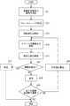
- FIG. 4 is a flowchart showing a specific flow of the inspection method of the present embodiment.
- the inspector sets a plurality of vibration frequencies and an amplitude when the inspected body 6 is vibrated via the display unit 9 (S11).
- the vibration frequency at which the foreign matter floats differs depending on, for example, the relationship between the average particle size of the powder 6b and the volume of the foreign matter expected to be mixed in the object 6 to be inspected.
- a plurality of vibration frequencies are set based on the average particle size of 6b and the volume of foreign matter expected to be mixed in the object 6 to be inspected.
- the vibration frequency is set between 10 Hz and 500 Hz or less.
- the amplitude when the object to be inspected 6 is vibrated is set to be 10 times or more the average particle size of the powder 6b.
- the amplitude when the object to be inspected 6 is vibrated may be any amplitude as long as the foreign matter floats.
- the average particle size can be calculated in advance by an image analysis method, a shading method, a Coulter method, a precipitation method, a laser analysis, a scattering method, or the like. That is, the average particle size can be calculated by using a general method for calculating the particle size.
- the control unit 8 sets the frame rate of the imaging unit 4 based on the set vibration frequencies (S12). ..
- the control unit 8 sets the frame rate to be equal to or higher than the maximum vibration frequency of the set vibration frequency. For example, the control unit 8 sets the frame rate of the imaging unit 4 to 100 fps.
- control unit 8 sets the rotation speed of the stage 2a of the vibration unit 2 based on the set frame rate (S13). For example, when the fineness of a long and thin foreign matter such as hair is smaller than one pixel of the imaging unit 4, the foreign matter may not be captured well even if the foreign matter is imaged from the longitudinal direction of the foreign matter.
- control unit 8 is set so that three or more images of the inspected body 6 can be captured while the stage 2a of the vibrating unit 2 goes around based on the set frame rate.
- the rotation speed of the stage 2a of the vibrating unit 2 may not be the rotation speed at which only the facing portion of the inspected body 6 is imaged by the rotation of the stage 2a.
- the vibrating unit 2 is arranged in a state where the inspected body 6 is arranged on the stage 2a so that the center of the inspected body 6 is generally arranged on the rotation axis of the vibrating unit 2. Is controlled to rotate the stage 2a while vibrating (S14).
- control unit 8 selects one of the set vibration frequencies, and vibrates the stage 2a with the selected vibration frequency and the set amplitude, and the set stage 2a.
- the stage 2a is rotated at the rotation speed.
- the body 6 to be inspected can be vibrated and rotated (that is, rotated) about the rotation axis of the vibrating portion 2.
- the control unit 8 controls the light source 3 to irradiate substantially the entire upper surface of the powder 6b of the object 6 to be inspected rotating while vibrating, and controls the imaging unit 4 to control the powder 6b.
- the entire upper surface of the above surface is imaged (S15).
- the imaging unit 4 acquires image information of three or more images at substantially equal intervals in the circumferential direction of the object 6 to be inspected, and outputs the acquired image information to the determination unit 5.
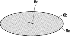
- FIG. 5 is a diagram showing image information obtained by imaging the upper surface of the powder.
- the speed of ascending inside the powder 6b differs depending on the specific gravity of the foreign matter 6d that is expected to be mixed in the object 6 to be inspected. Therefore, the period during which the foreign matter 6d, which is expected to be mixed in the object 6 to be inspected, reaches from the bottom surface of the container 6a to the top surface of the powder 6b is acquired in advance by simulation or experiment, and is the longest of the acquired periods. It is preferable to rotate the object to be inspected 6 while vibrating it for a period of more than one period. As a result, as shown in FIG. 5, the foreign matter 6d is exposed on the upper surface of the powder 6b.
- the period for rotating the object to be inspected 6 while vibrating may be set in advance, or may be set by the inspector via the display unit 9.
- the determination unit 5 determines whether or not the foreign matter 6d is detected based on the image information (S16). Specifically, the determination unit 5 calculates the difference in pixel values (that is, the difference between frames) of the corresponding pixels (that is, equal pixels) in the adjacent image information in time series, and the frame is equal to or larger than a preset threshold value. Determine if there is a difference between them. The difference between frames and the threshold value are absolute values.
- the determination unit 5 determines that the foreign matter 6d has been detected (YES in S16), and determines that the inspected body 6 is a defective product. Output to 8 (S17).
- the control unit 8 controls, for example, a robot arm (not shown) to carry the inspected body 6 to the defective product lane and perform an inspection operation. To finish.
- the determination unit 5 determines that the foreign matter 6d has not been detected (NO in S16), and determines that the inspected object 6 is a good product. Output to the control unit 8 (S18).
- the control unit 8 determines whether or not the inspected body 6 is vibrated at all the set vibration frequencies (S19). When the control unit 8 determines that the inspected body 6 is vibrated at all the set vibration frequencies (YES in S19), for example, the control unit 8 controls the robot arm (not shown) to carry the inspected body 6 to the non-defective lane. Then, the inspection work is completed.
- the control unit 8 determines that the inspected body 6 is not vibrating at all the set vibration frequencies (NO in S19)
- the control unit 8 executes the steps S14 to S19 at different vibration frequencies.
- the average value of the inter-frame difference of each pixel when the object 6 to be inspected was vibrated last time was calculated (S20), and the average value of the inter-frame difference of the pixels calculated last time was calculated this time. It may be subtracted from the frame-to-frame difference in the pixel.
- the inspection device 1 and the inspection method of the present embodiment can detect the inclusion of foreign matter 6d having a different volume by vibrating the inspected body 6 by changing the vibration frequency stepwise. Therefore, the inspection device 1 and the inspection method of the present embodiment can improve the inspection accuracy of the inspected body 6.
- the object to be inspected 6 is rotated to image a plurality of parts in the circumferential direction of the object to be inspected 6 (that is, the object to be inspected 6 is imaged from different directions), a foreign object is formed. Even if 6d is a long and thin object such as hair and one image information cannot capture the foreign matter 6d, the other image information can capture the foreign matter 6d. Therefore, the inspection accuracy of the inspected body 6 can be improved.
- the upper surface of the powder 6b is imaged at a frame rate equal to or higher than the maximum vibration frequency, there is a high possibility that the moment when the foreign matter 6d is exposed on the upper surface of the powder 6b can be imaged.
- the pixel group corresponding to the portion where the shadow appears on the upper surface of the powder 6b corresponds to the adjacent image information in time series as compared with the pixel group corresponding to the portion where the shadow does not appear on the upper surface of the powder 6b.
- the difference between pixel frames is small.
- the steps S11 to S15 are executed in advance using the object 6 to be inspected as a sample, and based on the acquired image information, the first pixel group corresponding to the portion where the shadow appears on the upper surface of the powder 6b and the shadow do not appear. It is discriminated from the second pixel group corresponding to the portion.
- the frame-to-frame difference of the corresponding pixel in the adjacent image information in time series is calculated, and the average value of the frame-to-frame difference in the first pixel group and the average value of the frame-to-frame difference in the second pixel group are calculated. To do.
- the first The calculated ratio may be integrated with the pixel values of the pixels of the pixel group to correct the pixel values.
- the threshold value used for detecting the foreign matter 6d in the first pixel group may be set to a value divided by the calculated ratio. That is, the threshold value used for detecting the foreign matter 6d in the first pixel group may be reduced by the calculated ratio to the threshold value used for detecting the foreign matter 6d in the second pixel group.
- the present invention has been described as a hardware configuration, but the present invention is not limited thereto.
- the present invention can also be realized by causing a CPU (Central Processing Unit) to execute a computer program to process each component.
- a CPU Central Processing Unit
- FIG. 6 is a diagram showing an example of the hardware configuration included in the processing device 7.
- the device 70 shown in FIG. 6 includes a processor 72 and a memory 73 together with the interface 71.
- the processing device 7 described in the above-described embodiment is realized by the processor 72 reading and executing the program stored in the memory 73. That is, this program is a program for causing the processor 72 to function as the processing device 7 of FIG.
- Non-temporary computer-readable media include various types of tangible storage media.
- Examples of non-transitory computer-readable media include magnetic recording media (eg, flexible disks, magnetic tapes, hard disk drives), magneto-optical recording media (eg, magneto-optical disks).
- this example includes a CD-ROM (Read Only Memory), a CD-R, and a CD-R / W.
- semiconductor memories eg, mask ROM, PROM, EPROM, flash ROM, RAM.
- the program may also be supplied to the computer by various types of temporary computer readable media. Examples of temporary computer-readable media include electrical, optical, and electromagnetic waves.
- the temporary computer-readable medium can supply the program to the computer via a wired communication path such as an electric wire and an optical fiber, or a wireless communication path.
- a plurality of parts having different circumferential directions of the inspected body 6 are imaged by rotating the inspected body 6, but the inspected body 6 is not rotated.
- a plurality of imaging units 4 By arranging a plurality of imaging units 4 around the body 6, a plurality of portions of the inspected body 6 having different circumferential directions may be imaged.
- the inspected body 6 is rotated around the rotation axis of the vibrating portion 2, the inspected body 6 may be arranged so that the inspected body 6 revolves around the rotation axis of the vibrating portion 2. Good. In short, it suffices if different parts can be imaged in the circumferential direction of the object 6 to be inspected.
- the vibration frequency is set according to the average particle size of the powder 6b and the volume of the foreign matter 6d that is expected to be mixed in the object 6 to be inspected.
- the particle size distribution of the powder 6b The vibration frequency may be set according to the volume of the foreign matter 6d that is expected to be mixed in the object 6 to be inspected. Further, the vibration frequency may be set according to the surface area or volume of the powder 6b and the volume of the foreign matter 6d that is expected to be mixed in the object 6 to be inspected. Further, the vibration frequency may be set according to the friction between the powder 6b and the object to be inspected 6.
- the vibrating unit 2 of the above-described embodiment has a configuration in which the inspected body 6 is placed, but it may also have a configuration in which the inspected body 6 is gripped to vibrate or rotate the inspected body 6. .. Further, the vibrating unit 2 may be, for example, a transfer table of the inspected body 6 arranged on the transfer line of the inspected body 6. In short, the vibrating unit 2 may have at least a configuration capable of vibrating the inspected body 6.
- Inspection device Vibration unit, 2a Stage 3 Light source 4 Imaging unit 5 Judgment unit 6 Inspected object, 6a container, 6b powder, 6c plug, 6d Foreign matter 7 Processing device 8 Control unit 9 Display unit 70 device, 71 interface, 72 Processor, 73 memory
Landscapes
- Engineering & Computer Science (AREA)
- General Physics & Mathematics (AREA)
- Physics & Mathematics (AREA)
- Computer Vision & Pattern Recognition (AREA)
- Theoretical Computer Science (AREA)
- General Health & Medical Sciences (AREA)
- Health & Medical Sciences (AREA)
- Multimedia (AREA)
- Chemical & Material Sciences (AREA)
- Life Sciences & Earth Sciences (AREA)
- Pathology (AREA)
- Immunology (AREA)
- Biochemistry (AREA)
- Analytical Chemistry (AREA)
- Quality & Reliability (AREA)
- Evolutionary Computation (AREA)
- Mechanical Engineering (AREA)
- Artificial Intelligence (AREA)
- Computing Systems (AREA)
- Databases & Information Systems (AREA)
- Software Systems (AREA)
- Medical Informatics (AREA)
- Signal Processing (AREA)
- Investigating Materials By The Use Of Optical Means Adapted For Particular Applications (AREA)
Priority Applications (4)
| Application Number | Priority Date | Filing Date | Title |
|---|---|---|---|
| JP2021506875A JP7238964B2 (ja) | 2019-03-19 | 2019-03-19 | 検品装置、検品方法、及びプログラム |
| EP19920093.2A EP3943921B1 (en) | 2019-03-19 | 2019-03-19 | Inspection device, inspection method, and non-transitory computer-readable medium |
| US17/437,631 US11972555B2 (en) | 2019-03-19 | 2019-03-19 | Product-inspection apparatus, product-inspection method, and non-transitory computer readable medium |
| PCT/JP2019/011346 WO2020188728A1 (ja) | 2019-03-19 | 2019-03-19 | 検品装置、検品方法、及び非一時的なコンピュータ可読媒体 |
Applications Claiming Priority (1)
| Application Number | Priority Date | Filing Date | Title |
|---|---|---|---|
| PCT/JP2019/011346 WO2020188728A1 (ja) | 2019-03-19 | 2019-03-19 | 検品装置、検品方法、及び非一時的なコンピュータ可読媒体 |
Publications (1)
| Publication Number | Publication Date |
|---|---|
| WO2020188728A1 true WO2020188728A1 (ja) | 2020-09-24 |
Family
ID=72519278
Family Applications (1)
| Application Number | Title | Priority Date | Filing Date |
|---|---|---|---|
| PCT/JP2019/011346 Ceased WO2020188728A1 (ja) | 2019-03-19 | 2019-03-19 | 検品装置、検品方法、及び非一時的なコンピュータ可読媒体 |
Country Status (4)
| Country | Link |
|---|---|
| US (1) | US11972555B2 (https=) |
| EP (1) | EP3943921B1 (https=) |
| JP (1) | JP7238964B2 (https=) |
| WO (1) | WO2020188728A1 (https=) |
Citations (11)
| Publication number | Priority date | Publication date | Assignee | Title |
|---|---|---|---|---|
| JPS537459B2 (https=) | 1976-04-12 | 1978-03-17 | ||
| JPH01272948A (ja) * | 1988-04-26 | 1989-10-31 | Mitsubishi Heavy Ind Ltd | 実ビン内異物検査方法 |
| JP2000298103A (ja) * | 1999-04-15 | 2000-10-24 | Nittetsu Mining Co Ltd | 透明容器内粉末の異物検査装置 |
| JP2001004549A (ja) * | 1999-06-24 | 2001-01-12 | Dai Ichi Seiyaku Co Ltd | 粉体中の異物検出装置 |
| JP2004257937A (ja) * | 2003-02-27 | 2004-09-16 | Japan System Kk | 異物検査装置および検査方法 |
| JP2005030810A (ja) * | 2003-07-08 | 2005-02-03 | Asahi Shuzo Kk | 異物検査装置 |
| JP2010008339A (ja) * | 2008-06-30 | 2010-01-14 | Decsys:Kk | 透明容器内粉末中の異物検査方法及び異物検査装置 |
| JP2011080936A (ja) * | 2009-10-09 | 2011-04-21 | Eisai Machinery Co Ltd | 異物検査装置及び方法 |
| JP2014006186A (ja) * | 2012-06-26 | 2014-01-16 | Fuji Electric Co Ltd | 異物検査装置 |
| JP2014145652A (ja) * | 2013-01-29 | 2014-08-14 | Fuji Electric Co Ltd | 異物検査装置 |
| WO2018002049A1 (en) * | 2016-06-28 | 2018-01-04 | F. Hoffmann-La Roche Ag | Inspection device |
Family Cites Families (6)
| Publication number | Priority date | Publication date | Assignee | Title |
|---|---|---|---|---|
| JP2719410B2 (ja) * | 1989-07-19 | 1998-02-25 | 日鉄鉱業株式会社 | 粉末密封透明容器の自動検査装置 |
| JP2012220453A (ja) * | 2011-04-13 | 2012-11-12 | Eisai Machinery Co Ltd | 異物検出装置 |
| JP5994416B2 (ja) * | 2012-06-18 | 2016-09-21 | ニプロ株式会社 | テラヘルツパルス波を用いた粉末中の異物検出装置および異物検出方法 |
| JPWO2014064897A1 (ja) * | 2012-10-25 | 2016-09-08 | 日本電気株式会社 | 情報処理装置、情報処理方法および情報処理プログラム |
| CN106312062B (zh) * | 2016-08-02 | 2018-09-25 | 西安铂力特增材技术股份有限公司 | 一种检验铺粉质量的方法及增材制造设备 |
| US11344949B2 (en) * | 2018-06-08 | 2022-05-31 | General Electric Company | Powder removal floating structures |
-
2019
- 2019-03-19 WO PCT/JP2019/011346 patent/WO2020188728A1/ja not_active Ceased
- 2019-03-19 JP JP2021506875A patent/JP7238964B2/ja active Active
- 2019-03-19 EP EP19920093.2A patent/EP3943921B1/en active Active
- 2019-03-19 US US17/437,631 patent/US11972555B2/en active Active
Patent Citations (11)
| Publication number | Priority date | Publication date | Assignee | Title |
|---|---|---|---|---|
| JPS537459B2 (https=) | 1976-04-12 | 1978-03-17 | ||
| JPH01272948A (ja) * | 1988-04-26 | 1989-10-31 | Mitsubishi Heavy Ind Ltd | 実ビン内異物検査方法 |
| JP2000298103A (ja) * | 1999-04-15 | 2000-10-24 | Nittetsu Mining Co Ltd | 透明容器内粉末の異物検査装置 |
| JP2001004549A (ja) * | 1999-06-24 | 2001-01-12 | Dai Ichi Seiyaku Co Ltd | 粉体中の異物検出装置 |
| JP2004257937A (ja) * | 2003-02-27 | 2004-09-16 | Japan System Kk | 異物検査装置および検査方法 |
| JP2005030810A (ja) * | 2003-07-08 | 2005-02-03 | Asahi Shuzo Kk | 異物検査装置 |
| JP2010008339A (ja) * | 2008-06-30 | 2010-01-14 | Decsys:Kk | 透明容器内粉末中の異物検査方法及び異物検査装置 |
| JP2011080936A (ja) * | 2009-10-09 | 2011-04-21 | Eisai Machinery Co Ltd | 異物検査装置及び方法 |
| JP2014006186A (ja) * | 2012-06-26 | 2014-01-16 | Fuji Electric Co Ltd | 異物検査装置 |
| JP2014145652A (ja) * | 2013-01-29 | 2014-08-14 | Fuji Electric Co Ltd | 異物検査装置 |
| WO2018002049A1 (en) * | 2016-06-28 | 2018-01-04 | F. Hoffmann-La Roche Ag | Inspection device |
Non-Patent Citations (1)
| Title |
|---|
| See also references of EP3943921A4 |
Also Published As
| Publication number | Publication date |
|---|---|
| JP7238964B2 (ja) | 2023-03-14 |
| EP3943921A1 (en) | 2022-01-26 |
| EP3943921A4 (en) | 2022-03-16 |
| JPWO2020188728A1 (https=) | 2020-09-24 |
| US20220148144A1 (en) | 2022-05-12 |
| EP3943921B1 (en) | 2024-10-16 |
| US11972555B2 (en) | 2024-04-30 |
Similar Documents
| Publication | Publication Date | Title |
|---|---|---|
| JP7216146B2 (ja) | 流体中の非溶解粒子の非破壊的検出のための方法および装置 | |
| JP5918508B2 (ja) | 液相中の固形物検出用の装置および方法 | |
| CN107664644A (zh) | 一种基于机器视觉的物件表观自动检测装置及方法 | |
| CN109827974B (zh) | 一种树脂滤光片膜裂检测设备及检测方法 | |
| WO2017104662A1 (ja) | 粒子分析装置及び粒子分析方法 | |
| CN104122264A (zh) | 外观瑕疵检测系统及方法 | |
| CN103119395A (zh) | 玻璃瓶检查装置 | |
| JP2020139749A (ja) | 粉体封入容器の製造方法 | |
| JP2022122072A (ja) | 異物検出方法、異物検出システムおよびプログラム | |
| US20220146437A1 (en) | Product-inspection apparatus, product-inspection method, and non-transitory computer readable medium | |
| WO2020188728A1 (ja) | 検品装置、検品方法、及び非一時的なコンピュータ可読媒体 | |
| JP4906602B2 (ja) | 多結晶シリコン基板の欠陥検査装置および欠陥検査方法 | |
| US11977208B2 (en) | Removal of liquid drops from optical element | |
| JP4163039B2 (ja) | 容器内気泡判定方法及びその装置 | |
| US11325157B2 (en) | Device and method for capturing movement patterns of tumbler screening machines | |
| US12148143B2 (en) | Product-inspection apparatus, product-inspection method, and non-transitory computer readable medium | |
| JP2019219310A (ja) | 塗布膜評価装置、及び塗布膜評価方法 | |
| JPH11337470A (ja) | フロー式粒子画像分析装置 | |
| CN108401441A (zh) | 对待检测物质进行拉曼检测的方法和终端 | |
| JP2021143983A (ja) | 状態量測定装置、状態量測定方法及びコンピュータプログラム | |
| JP2005127790A (ja) | 粒子画像分析方法と装置およびそのプログラムと記録媒体 | |
| JP2006194788A (ja) | 粒子画像処理方法と装置およびそのプログラム | |
| WO2025062844A1 (ja) | 検査システム、検査方法、およびプログラム | |
| JP2000074816A (ja) | 粒子解析装置 | |
| JP2025109507A (ja) | 外観検査装置及び外観検査方法 |
Legal Events
| Date | Code | Title | Description |
|---|---|---|---|
| 121 | Ep: the epo has been informed by wipo that ep was designated in this application |
Ref document number: 19920093 Country of ref document: EP Kind code of ref document: A1 |
|
| ENP | Entry into the national phase |
Ref document number: 2021506875 Country of ref document: JP Kind code of ref document: A |
|
| NENP | Non-entry into the national phase |
Ref country code: DE |
|
| ENP | Entry into the national phase |
Ref document number: 2019920093 Country of ref document: EP Effective date: 20211019 |