WO2020184370A1 - 燃料噴射弁の作動検出装置及び作動検出方法 - Google Patents
燃料噴射弁の作動検出装置及び作動検出方法 Download PDFInfo
- Publication number
- WO2020184370A1 WO2020184370A1 PCT/JP2020/009368 JP2020009368W WO2020184370A1 WO 2020184370 A1 WO2020184370 A1 WO 2020184370A1 JP 2020009368 W JP2020009368 W JP 2020009368W WO 2020184370 A1 WO2020184370 A1 WO 2020184370A1
- Authority
- WO
- WIPO (PCT)
- Prior art keywords
- fuel injection
- injection valve
- timing
- valve
- vibration
- Prior art date
- Legal status (The legal status is an assumption and is not a legal conclusion. Google has not performed a legal analysis and makes no representation as to the accuracy of the status listed.)
- Ceased
Links
Images



Classifications
-
- F—MECHANICAL ENGINEERING; LIGHTING; HEATING; WEAPONS; BLASTING
- F02—COMBUSTION ENGINES; HOT-GAS OR COMBUSTION-PRODUCT ENGINE PLANTS
- F02D—CONTROLLING COMBUSTION ENGINES
- F02D45/00—Electrical control not provided for in groups F02D41/00 - F02D43/00
Definitions
- the present invention relates to a fuel injection valve operation detection device and an operation detection method for detecting the opening / closing timing of the fuel injection valve.
- Patent Document 1 For the purpose of acquiring the injection characteristics of the fuel injection valve, as described in Japanese Patent Application Laid-Open No. 2009-57924 (Patent Document 1), fuel injection is performed according to a change in the fuel pressure supplied to the fuel injection valve. A technique for detecting the opening / closing timing of a valve has been proposed.
- the change in the fuel pressure is small because the injection time is short, and in the conventional technique, the fuel injection valve is used. It was difficult to detect the opening / closing timing of the fuel with high accuracy. Further, even when the split injection is not performed, when the load of the internal combustion engine is small, the change in fuel pressure is small because one injection time is short, and the opening / closing timing of the fuel injection valve is adjusted as in the split injection. It was difficult to detect with high accuracy.
- an object of the present invention is to provide an operation detection device and an operation detection method for a fuel injection valve, which can detect the opening / closing timing of the fuel injection valve with high accuracy regardless of the magnitude of the fuel injection amount. ..
- the operation detection device of the fuel injection valve capable of reading the output signal of the vibration sensor that detects the vibration of the internal combustion engine is fuel based on the vibration parameter obtained from the output signal of the vibration sensor and the rotation angle of the internal combustion engine. At least one of the valve opening timing and the valve closing timing of the injection valve is detected.
- an electronic control unit capable of reading the output signal of the vibration sensor that detects the vibration of the internal combustion engine opens the fuel injection valve based on the vibration parameter obtained from the output signal of the vibration sensor and the rotation angle of the internal combustion engine. Detects at least one of timing and valve closing timing.
- At least one of the fuel injection valve opening timing and the valve closing timing is detected by the vibration of the internal combustion engine, so that the opening / closing timing of the fuel injection valve can be performed with high accuracy regardless of the amount of fuel injection. Can be detected.
- FIG. 1 shows an example of an engine system in which an operation detection device for a fuel injection valve according to the present embodiment is incorporated.
- the intake pipe 120 connected to the intake manifold 110 of the internal combustion engine 100 has an air cleaner 130 that filters and removes dust and the like in the intake along the intake flow direction, a throttle valve 140 that adjusts the intake flow, and an intake flow. Hot wire type air flow meters 150 for detecting the intake air temperature are arranged in this order. Further, the intake pipe 120 is provided with an auxiliary intake passage 120A that bypasses the throttle valve 140. The auxiliary intake passage 120A is provided with an idle control valve 160 that increases the intake flow rate according to, for example, a warm-up state and an operating state of an air conditioner.
- the intake manifold 110 is equipped with a fuel injection valve 170 that injects fuel into an intake port that communicates with each cylinder.
- the valve spring urges the plunger toward the valve seat to close the valve, and when the solenoid is energized, the fuel injection valve 170 separates the plunger from the valve seat against the urging force of the valve spring.
- It is an electronically controlled injector that moves in the direction to open the valve.
- the fuel injection valve 170 is provided with a stopper that regulates the movement of the plunger when the valve is opened.
- the plunger when the valve is changed from the closed state to the valve open state, the plunger hits the stopper and vibration of the first predetermined frequency is generated, and when the valve is changed from the valve open state to the valve closed state, the plunger is moved. It has the characteristic that it hits the valve seat and vibrates at a second predetermined frequency.
- the first predetermined frequency and the second predetermined frequency are determined according to, for example, the material and shape of the plunger, the valve seat, and the stopper.
- the fuel stored in the fuel tank 180 is sucked up by the fuel pump 190 and supplied to the pressure regulator 210 via the fuel supply pipe 200.
- the fuel supplied to the pressure regulator 210 is supplied to the fuel injection valve 170 while being adjusted to a predetermined fuel pressure. Therefore, the fuel injection valve 170 can inject a fuel injection amount substantially proportional to the valve opening time into the intake port. Further, among the fuel supplied to the fuel injection valve 170, the fuel not used for injection is returned to the fuel tank 180 via the fuel return pipe 220.
- the exhaust pipe 240 connected to the exhaust manifold 230 of the internal combustion engine 100 is provided with a three-way catalytic converter 250 that simultaneously reduces carbon monoxide, hydrocarbons, and nitrogen oxides in the exhaust along the exhaust flow direction, and exhaust noise.
- the muffler 260 to be reduced is arranged in this order.
- oxygen concentration sensors 270 and 280 for detecting the oxygen concentration in the exhaust gas are attached to the upstream and downstream sides of the exhaust gas of the three-way catalyst converter 250, respectively.
- an ignition plug 320 is attached to the cylinder head 290 of the internal combustion engine 100 so as to face the combustion chamber 310 formed in the cylinder block 300.
- the spark plug 320 ignites the air-fuel mixture injected from the fuel injection valve 170 and the intake air (air) to push down the piston 330 toward the crankshaft to generate a rotational driving force.
- the throttle opening sensor 340 for detecting the opening degree of the throttle valve 140, a predetermined position (for example, the top dead point)
- a crank angle sensor 350 for detecting the crank angle and the number of rotations based on the above
- a cam angle sensor 360 for determining the cylinder
- a water temperature sensor 370 for detecting the water temperature
- a vibration sensor 380 for detecting the vibration of the internal combustion engine 100 are provided. ..
- the vibration sensor 380 a knock sensor that detects knocking can be diverted.
- the output signals of the air flow meter 150, the oxygen concentration sensors 270 and 280, the throttle opening sensor 340, the crank angle sensor 350, the cam angle sensor 360, the water temperature sensor 370, and the vibration sensor 380 are sent to the electronic control unit 390 having a built-in microcomputer. It has been entered. Further, the idle control valve 160, the fuel injection valve 170, the fuel pump 190, and the ignition plug 320 are electrically connected to the electronic control device 390 and operate appropriately according to the operation signal output from the electronic control device 390. ..
- the electronic control device 390 includes a clock generation circuit 390A, a CPU (Central Processing Unit) 390B, a ROM (Read Only Memory) 390C, a RAM (Random Access Memory) 390D, and a timer counter 390E.
- the output circuit 390F, the digital input circuit 390G, the analog input circuit 390H, the internal bus 390I, the input / output interface (I / O) 390J, and the conversion circuit 390K are built-in.
- the clock generation circuit 390A generates a clock pulse for synchronizing each circuit, and supplies the clock pulse to the CPU 390B.
- the CPU 390B processes data for achieving a required object by reading, interpreting, and executing a control program or the like in synchronization with the clock pulse supplied from the clock generation circuit 390A.
- the ROM 390C is a non-volatile memory capable of holding data even when the power supply is cut off, and stores a control program, control data, learning values, failure information, and the like.
- the RAM 390D is a volatile memory in which data is lost when the power supply is cut off, and temporarily stores the calculation result of the CPU 390B and the like.
- the timer counter 390E performs timekeeping and counting related to control.
- the CPU 390B, ROM 390C, RAM 390D, and timer counter 390E are each connected to the internal bus 390I.
- the output circuit 390F provides an output port for outputting an analog signal or a digital signal to an external device or the like.
- the digital input circuit 390G provides an input port for receiving a digital signal from an external device or the like.
- the analog input circuit 390H provides an input port for receiving an analog signal from an external device or the like.
- the output circuit 390F and the digital input circuit 390G are connected to the internal bus 390I via an input / output interface 390J that converts the output signal of the CPU 390B into a signal that can be processed by the CPU 390B or a signal suitable for an external device or the like. ing.
- the analog input circuit 390H is internally provided via a conversion circuit 390K having an analog-to-digital conversion function for converting an analog signal into a digital signal and a fast Fourier transform (FFT) function for converting an analog signal into a high-speed Fourier transform. It is connected to bus 390I. Therefore, the CPU 390B, ROM 390C, RAM 390D, timer counter 390E, output circuit 390F, digital input circuit 390G, and analog input circuit 390H can transmit and receive arbitrary data via the internal bus 390I.
- FFT fast Fourier transform
- the electronic control device 390 electronically controls the idle control valve 160, the fuel injection valve 170, the fuel pump 190, and the spark plug 320 according to various control programs stored in the ROM 390C. Specifically, the electronic control unit 390 needs to determine whether or not it is necessary to increase the intake air flow rate according to the output signal of the water temperature sensor 370 and the operating state of the air conditioner, and increase the intake air flow rate. When it is determined that there is, an operation signal is output to the idle control valve 160 to increase the opening area of the auxiliary intake passage 120A. Further, the electronic control unit 390 obtains a basic fuel injection amount according to the intake flow rate signal output from the air flow meter 150 and the rotation speed signal output from the crank angle sensor 350.
- the electronic control unit 390 obtains a fuel injection amount obtained by appropriately correcting the basic fuel injection amount according to the output signals of the water temperature sensor 370, the oxygen concentration sensors 270 and 280, and sends an operation signal to the fuel injection valve 170 at a predetermined timing. Is output, and fuel is injected into the intake port according to the fuel injection amount from the nozzle at the tip. At this time, the electronic control unit 390 outputs an operation signal to the spark plug 320 at a predetermined timing when the fuel injection is completed to ignite the air-fuel mixture. Further, the electronic control unit 390 outputs an operation signal to the fuel pump 190, and causes the fuel pump 190 to supply the fuel stored in the fuel tank 180 to the fuel injection valve 170.
- the principle of detecting the opening / closing timing of the fuel injection valve 170 will be described with reference to FIG.
- vibration of the first predetermined frequency is generated
- the fuel injection valve 170 has a second predetermined frequency. It has the characteristic of generating vibration.
- the plunger causes the plunger in the process of converging the drive current of the fuel injection valve 170 to the target current by feedback control.
- vibration of the first predetermined frequency is generated.
- the plunger hits the valve seat and vibration of a second predetermined frequency is generated in the process of reducing the drive current of the fuel injection valve 170 to zero.
- a window that specifies the period for sampling vibration (start timing to end timing) is introduced, and vibration is sampled during the period specified by this window. Then, the sampled vibration is subjected to a fast Fourier transform (FFT) to convert it into a frequency, and the power spectrum (signal strength) of that frequency is analyzed to open / close the fuel injection valve 170, that is, the valve opening timing and the valve closing timing.
- FFT fast Fourier transform
- the power spectrum signal strength
- Detect timing if the power spectrum decreases due to a change in fuel pressure, it becomes difficult to analyze the power spectrum. Therefore, by changing the drive current of the fuel injection valve 170 to secure the power spectrum, the opening / closing timing of the fuel injection valve 170 can be determined. The detection accuracy can be improved.
- the CPU 390B of the electronic control unit 390 implements each function as shown in FIG. 4 according to the control program stored in the ROM 390C in order to detect the opening / closing timing of the fuel injection valve 170.
- the electronic control unit 390 calculates the fuel injection amount and the retardation state of the ignition timing in real time according to the operating state of the internal combustion engine 100 (the same applies hereinafter). ..
- the electronic control unit 390 has, as each function, a rotation time calculation unit 400, an injection time calculation unit 410, an injection start timing calculation unit 420, a window number calculation unit 430, a sampling execution unit 440, a frequency conversion unit 450, and a valve opening timing detection unit. 460, a valve closing timing detection unit 470, and an actual injection time calculation unit 480 are mounted.
- the predetermined angle is not limited to 1 degree, but may be any angle such as 0.5 degree, 1.5 degree, or 2 degree in consideration of the required detection accuracy and the like.
- the injection time calculation unit 410 calculates the fuel injection time TIOUT [ ⁇ s] required for the fuel injection valve 170 to inject the fuel corresponding to the fuel injection amount based on the fuel injection amount, the load, and the fuel pressure.
- the fuel pressure can be a predetermined fuel pressure adjusted by the pressure regulator 210. That is, the injection time calculation unit 410 considers that the time required to inject a constant amount of fuel changes according to the load and the fuel pressure, and the fuel injection required to inject the fuel corresponding to the fuel injection amount. Calculate the time TIOUT.
- the injection time calculation unit 410 may calculate at least the fuel injection time TIOUT according to the fuel injection amount and the fuel pressure.
- the injection start timing calculation unit 420 calculates the fuel injection start timing INJ_ST [deg] at which the fuel injection valve 170 starts fuel injection based on the retardation state of the rotation speed, the load, and the ignition timing.
- the injection start timing calculation unit 420 may calculate the fuel injection start timing INJ_ST based on the rotation speed and the load without using the retardation state of the ignition timing as one of the parameters.
- the fuel injection start timing INJ_ST can be defined as the rotation angle [deg] of the crankshaft from the reference position (the same applies to other timings).
- the number of windows calculation unit 430 calculates the number of windows (number of windows) INJ_CT having a predetermined fixed width necessary for detecting the opening / closing timing of the fuel injection valve 170 based on the rotation time CA1 and the fuel injection time TIOUT. .. Specifically, the window number calculation unit 430 calculates the window number INJ_CT by dividing the fuel injection time TIOUT by the rotation time CA1. Here, if the value obtained by dividing the fuel injection time TIOUT by the rotation time CA1 has a decimal point, it can be rounded up to an integer value.
- the fixed width can be appropriately determined in consideration of, for example, the injection characteristics of the fuel injection valve 170.
- the sampling execution unit 440 starts sampling the vibration by the window 1 when the crank angle reaches the fuel injection start timing INJ_ST or a predetermined timing on the advance side from this, and then the vibration by the windows 2 to INJ_CT at each predetermined angle. Sampling is started in sequence. Then, the sampling execution unit 440 samples the vibration VIB of the internal combustion engine 100 in each of the windows 1 to INJ_CT.
- the frequency conversion unit 450 uses the function of the conversion circuit 390K to convert the vibration VIB sampled using each window 1 to INJ_CT into a frequency FRQ [Hz], and converts the frequency FRQ into each window 1 to INJ_CT. Associate with. As shown in FIG. 3, the vibration VIB converted into the frequency FEQU is information indicating the relationship between the frequency and the power spectrum. Therefore, when the fuel injection valve 170 opens or closes, vibration is generated, and the peak of the power spectrum appears at the frequency corresponding to the vibration.
- the valve opening timing detection unit 460 detects the valve opening timing INJ_OP by sequentially referring to the frequency FEQU associated with each window 1 to INJ_CT. The method of detecting the opening timing of the fuel injection valve 170 will be described in detail in the flowchart described later.
- the valve closing timing detection unit 470 detects the valve closing timing INJ_CL by sequentially referring to the frequency FRQ associated with each window 1 to INJ_CT. The method of detecting the closing timing of the fuel injection valve 170 will be described in detail in the flowchart described later.
- the actual injection time calculation unit 480 subtracts the valve opening timing INJ_OP from the valve closing timing INJ_CL of the fuel injection valve 170 to obtain the actual fuel injection time [deg] in which the fuel injection valve 170 actually injects fuel. calculate.
- the actual fuel injection time may be not the angle of the crankshaft but the actual injection pulse width converted by a known method.
- the electronic control unit 390 opens and closes the fuel injection valve 170 based on the vibration parameters obtained from the output signal of the vibration sensor 380 and the rotation angle of the crankshaft of the internal combustion engine 100. At least one of can be detected. At this time, since the opening / closing timing of the fuel injection valve 170 is mainly detected by the vibration generated in the internal combustion engine 100, the influence of the magnitude of the fuel injection amount is small, and the opening / closing timing of the fuel injection valve 170 is detected with high accuracy. can do. Therefore, the opening / closing timing of the fuel injection valve 170 can be detected with high accuracy even in the divided injection in which the fuel is divided and injected a plurality of times in order to promote the mixing and vaporization of the fuel. If the processing capacity of the electronic control unit 390 has a margin, vibration sampling by the windows may be sequentially executed for each predetermined rotation of the crankshaft without calculating the number of windows INJ_CT and the fuel injection start timing INJ_ST. Good.
- FIGS. 5 and 6 show an example of the opening / closing timing detection process of the fuel injection valve 170, which is repeatedly executed by the CPU 390B of the electronic control unit 390 at predetermined time intervals when the electronic control unit 390 is activated. ..
- the opening / closing timing detection process shown in FIGS. 5 and 6 in addition to detecting the opening / closing timing of the fuel injection valve 170, the fuel injection valve 170 is also diagnosed.
- step 1 abbreviated as "S1" in the figure; the same applies hereinafter
- the CPU 390B reads the rotation speed signal output from the crank angle sensor 350 and calculates the rotation time CA1 required for the crankshaft to rotate by a predetermined angle. To do.
- the rotation time calculation unit 400 is implemented by the process of step 1.
- step 2 the CPU 390B reads the intake flow rate signal output from the air flow meter 150, which can be cited as an example of the load, and corresponds to the fuel injection amount in consideration of the fuel injection amount and the fuel pressure calculated by another process.
- the fuel injection time TIOUT required to inject the fuel to be injected from the fuel injection valve 170 is calculated.
- the load is not limited to the intake flow rate, but is a state quantity closely related to torque, such as the opening degree of the throttle valve 140 detected by the throttle opening degree sensor 340, the accelerator opening degree, the intake negative pressure, and the supercharging pressure. It can also be.
- the injection time calculation unit 410 is mounted by the process of step 2.
- step 3 the CPU 390B reads the intake flow rate signal output from the air flow meter 150 and the rotation speed signal output from the crank angle sensor 350, and considers the retardation state of the ignition timing calculated by another process, and fuel injection.
- the start timing INJ_ST is calculated.
- the injection start timing calculation unit 420 is implemented by the process of step 3.
- step 4 the CPU 390B calculates the number of windows INJ_CT based on the rotation time CA1 and the fuel injection time TIOUT.
- the number of windows INJ_CT may be reduced in order to reduce the processing load (the same applies hereinafter).
- the number of windows calculation unit 430 is implemented by the process of step 4.
- step 5 the CPU 390B reads the crank angle output from the crank angle sensor 350, and when the crank angle reaches the fuel injection start timing INJ_ST or a predetermined timing on the advance angle side, sampling of vibration by the window 1 is performed. After that, the sampling of vibrations by windows 2 to INJ_CT is sequentially started at predetermined angles. Then, the CPU 390B reads and samples the vibration output from the vibration sensor 380 in each of the windows 1 to INJ_CT.
- the sampling execution unit 440 is implemented by the process of step 5.
- step 6 the CPU 390B uses the function of the conversion circuit 390K to convert the vibrations sampled using each window 1 to INJ_CT into frequencies, respectively.
- the CPU 390B may convert the vibration into a frequency by software without using the function of the conversion circuit 390K.
- the frequency conversion unit 450 is mounted by the process of step 6.
- step 7 the CPU 390B sequentially refers to the frequencies associated with each window 1 to INJ_CT, and when the vibration of the first predetermined frequency generated by opening the fuel injection valve 170 disappears, immediately before that.
- the start timing of sampling using the window is detected as the valve opening timing INJ_OP.
- the valve opening timing detection unit 460 is mounted.
- step 8 the CPU 390B sequentially refers to the frequencies associated with each window 1 to INJ_CT, and when the vibration of the second predetermined frequency generated by closing the fuel injection valve 170 appears, that window is used.
- the start timing of the sampling is detected as the valve closing timing INJ_CL.
- the valve closing timing detection unit 470 is mounted by the process of step 8.
- step 9 the CPU 390B subtracts the valve opening timing INJ_OP from the valve closing timing INJ_CL of the fuel injection valve 170 to calculate the actual fuel injection time during which the fuel injection valve 170 actually injected fuel.
- the actual injection time calculation unit 480 is implemented by the process of step 9.
- step 10 the CPU 390B compares the actual fuel injection time calculated in step 9 with the fuel injection time TIOUT (instructed fuel injection time) calculated in step 2 to determine whether or not the actual fuel injection time is abnormal. judge. Specifically, the CPU 390B determines whether or not the actual fuel injection time is abnormal based on whether or not the actual fuel injection time deviates from the fuel injection time TIOUT by a predetermined time or more. Then, if the CPU 390B determines that the actual fuel injection time is abnormal (Yes), the process proceeds to step 12. On the other hand, if the CPU 390B determines that the actual fuel injection time is not abnormal, that is, the actual fuel injection time is normal (No), the process proceeds to step 11.
- step 11 the CPU 390B compares the fuel injection start timing specified by the valve opening timing INJ_OP detected in step 7 with the fuel injection start timing INJ_ST (instructed injection start timing) calculated in step 3 to start fuel injection. Determine if the timing is abnormal. Specifically, the CPU 390B determines whether or not the injection start timing is abnormal depending on whether or not the fuel injection start timing specified by the valve opening timing INJ_OP deviates from the fuel injection start timing INJ_ST by a predetermined angle or more. To judge. Then, if the CPU 390B determines that the fuel injection start timing is abnormal (Yes), the process proceeds to step 12. On the other hand, if the CPU 390B determines that the fuel injection start timing is not abnormal, that is, the fuel injection start timing is normal (No), the process proceeds to step 13.
- step 12 the CPU 390B determines that the fuel injection valve 170 is abnormal.
- the CPU 390B can turn on the MIL (Malfunction Indicator Lamp) to notify the driver or the like, or store the failure information or the like in the ROM 390C. ..
- the CPU 390B determines that the fuel injection valve 170 is normal.
- the CPU 390B of the electronic control unit 390 uses a window that defines a period for sampling the output signal of the vibration sensor 380, and is retarded from the fuel injection start timing INJ_ST of the fuel injection valve 170 or a predetermined timing on the advance side.
- the output signal of the vibration sensor 380 is sampled a plurality of times and frequency-converted while gradually shifting toward the side.
- the CPU 390B of the electronic control unit 390 opens the fuel injection valve 170 based on the signal strength (power spectrum) of the frequency at the predetermined frequency (the first predetermined frequency and the second predetermined frequency) and the sampling start timing. Detects at least one of valve timing and valve closing timing.
- the CPU 390B of the electronic control unit 390 compares the valve opening timing INJ_OP of the fuel injection valve 170 with the fuel injection start timing INJ_ST to diagnose whether or not the fuel injection valve 170 is operating normally. Further, the CPU 390B of the electronic control unit 390 compares the actual fuel injection time and the fuel injection time TIOUT obtained by the valve opening timing and the valve closing timing of the fuel injection valve 170, and the fuel injection valve 170 operates normally. Diagnose whether or not.
- the CPU 390B of the electronic control unit 390 can determine that the fuel injection valve 170 has an abnormality when the power spectrum at a predetermined frequency is equal to or lower than a predetermined level. Further, in the CPU 390B of the electronic control unit 390, if there is an abnormality in the vibration sensor 380 or the power spectrum at a predetermined frequency is less than the allowable level smaller than the predetermined level, whether the fuel injection valve 170 is operating normally or not. You can also stop the diagnosis.
- the fuel injection valve 170 is assumed to open at 65 degrees from top dead center (TDC) and close at 90 degrees.
- TDC top dead center
- Window 1 samples vibrations in the range of 61 degrees to 76 degrees from top dead center. Since the fuel injection valve 170 opens at 65 degrees from the top dead center, the vibration sampling result using the window 1 shows the first predetermined value generated by the opening of the fuel injection valve 170 as shown in FIG. Frequency vibrations appear.
- Window 2 samples vibrations in the range of 63 to 78 degrees from top dead center. Since the fuel injection valve 170 opens at 65 degrees from the top dead center, the vibration sampling result using the window 2 shows the first predetermined value generated by the opening of the fuel injection valve 170 as shown in FIG. Frequency vibrations appear.
- the window 3 samples vibrations in the range of 65 to 80 degrees from top dead center. Since the fuel injection valve 170 opens at 65 degrees from the top dead center, the vibration sampling result using the window 3 shows the first predetermined value generated by the opening of the fuel injection valve 170 as shown in FIG. Frequency vibrations appear.
- Window 4 samples vibrations in the range of 67 to 82 degrees from top dead center. Since the fuel injection valve 170 opens at 65 degrees from top dead center and closes at 90 degrees, the vibration sampling result using the window 4 shows that the fuel injection valve 170 is opened as shown in FIG. Alternatively, the vibration of the first predetermined frequency or the second predetermined frequency generated by the valve closing does not appear. Therefore, it can be considered that the start timing of sampling using the window 3 immediately before the window 4 in which the vibration due to the valve opening does not appear is the valve opening timing INJ_OP of the fuel injection valve 170.
- the vibration of the first predetermined frequency or the second predetermined frequency generated by the opening or closing of the fuel injection valve 170 does not appear as in the window 4. ..
- the window 9 samples vibrations in the range of 75 to 90 degrees from top dead center. Since the fuel injection valve 170 closes at 90 degrees from the top dead center, the vibration sampling result using the window 9 shows the second predetermined value generated by the closing of the fuel injection valve 170 as shown in FIG. Frequency vibrations appear. Therefore, the sampling start timing of the window 9 in which the vibration due to the valve closing appears can be regarded as the valve closing timing INJ_CL of the fuel injection valve 170.
- the CPU 390B of the electronic control unit 390 can also implement each function as shown in FIG. 9 according to the control program stored in the ROM 390C in order to detect the opening / closing timing of the fuel injection valve 170.
- the electronic control unit 390 has, as each function, an injection start timing calculation unit 500, an injection time calculation unit 510, a window width calculation unit 520, a sampling execution unit 530, a frequency conversion unit 540, a valve opening timing detection unit 550, and a valve closing timing detection.
- a unit 560 and an actual injection time calculation unit 570 are mounted. Regarding the functions similar to the functions shown in FIG. 4, the explanations will be simplified in order to eliminate duplicate explanations. If necessary, refer to the description of the previous embodiment.
- the injection start timing calculation unit 500 calculates the fuel injection start timing INJ_ST [deg] at which the fuel injection valve 170 starts fuel injection based on the retardation state of the rotation speed, the load, and the ignition timing.
- the injection time calculation unit 510 determines the fuel injection time TIOUT [, which is required for the fuel injection valve 170 to inject fuel corresponding to the fuel injection amount, based on the fuel injection amount, the rotation speed, the load, the water temperature, the intake air temperature, and the fuel pressure. ⁇ s] is calculated. That is, the injection time calculation unit 510 considers that the time required to inject a constant amount of fuel changes according to the rotation speed, load, water temperature, intake air temperature, and fuel pressure, and the fuel corresponding to the fuel injection amount. The fuel injection time TIOUT required for injecting the fuel is calculated. The injection time calculation unit 510 may calculate at least the fuel injection time TIOUT according to the fuel injection amount and the fuel pressure.
- the window width calculation unit 520 calculates the variable width (window width) WIDTH [deg] of the window required to detect the opening / closing timing of the fuel injection valve 170 based on the fuel injection time TIOUT. Specifically, the window width calculation unit 520 calculates the fuel injection time TIOUT as the window width WIDTH. In this way, when vibration sampling using a window having a window width WIDTH is started at an appropriate timing, a first predetermined frequency and a first predetermined frequency generated by opening and closing the fuel injection valve 170 by one window are performed. Vibration of a predetermined frequency of 2 can be detected.
- the sampling execution unit 530 starts sampling of vibration using the window 1 when the crank angle reaches the fuel injection start timing INJ_ST or a predetermined timing on the advance angle side thereof, and then determines it in consideration of detection accuracy and the like.
- Sampling of vibrations using windows 2 to N (N: 3 or more natural numbers) is sequentially started at each predetermined angle.
- the number N of windows used for sampling the vibration can be an arbitrary fixed number, unlike the previous embodiment.
- the sampling execution unit 530 samples the vibration VIB of the internal combustion engine 100 in each of the windows 1 to N.
- the frequency conversion unit 540 uses the function of the conversion circuit 390K to convert the vibration VIB sampled using each of the windows 1 to N into the frequency FRQ [Hz], respectively, and converts the frequency FEQU into the frequencies 1 to N of each window 1 to N. Associate with.
- the valve opening timing detection unit 550 detects the valve opening timing INJ_OP by sequentially referring to the frequency FEQU associated with each of the windows 1 to N. The method of detecting the opening timing of the fuel injection valve 170 will be described in detail in the flowchart described later.
- the valve closing timing detection unit 560 detects the valve closing timing INJ_CL by sequentially referring to the frequency FEQU associated with each of the windows 1 to N. The method of detecting the closing timing of the fuel injection valve 170 will be described in detail in the flowchart described later.
- the actual injection time calculation unit 570 calculates the actual fuel injection time [deg] in which the fuel injection valve 170 actually injected fuel by subtracting the valve opening timing INJ_OP from the valve closing timing INJ_CL of the fuel injection valve 170. To do.
- the electronic control unit 390 uses the fuel injection valve 170 based on the vibration parameters obtained from the output signal of the vibration sensor 380 and the rotation angle of the crankshaft of the internal combustion engine 100, as in the previous embodiment. At least one of the valve opening timing and the valve closing timing can be detected. At this time, since the window width WIDTH of the window used for sampling the vibration is dynamically changed according to the fuel injection time TIOUT, the number of windows for sampling the vibration can be reduced, for example. The processing load of the electronic control unit 390 can be reduced. Since other actions and effects are the same as those in the previous embodiment, detailed description thereof will be omitted. If necessary, refer to the description of the previous embodiment.
- FIG. 10 shows another example of the opening / closing timing detection process of the fuel injection valve 170, which is repeatedly executed by the CPU 390B of the electronic control unit 390 at predetermined time intervals when the electronic control unit 390 is activated.
- the opening / closing timing detection process shown in FIG. 10 in addition to detecting the opening / closing timing of the fuel injection valve 170, the fuel injection valve 170 is also diagnosed, as in the previous embodiment. It should be noted that the same processing as that of the previous embodiment will be simplified in order to eliminate duplicate explanations. If necessary, refer to the description of the previous embodiment.
- step 21 the CPU 390B reads the intake flow rate output from the air flow meter 150 and the rotation speed signal output from the crank angle sensor 350, which can be cited as an example of the load, and the retard angle of the ignition timing calculated by another process.
- the fuel injection start timing INJ_ST is calculated in consideration of the state.
- the injection start timing calculation unit 500 is implemented by the process of step 21.
- step 22 the CPU 390B reads the intake flow signal and the intake temperature signal output from the air flow meter 150, the rotation speed signal output from the crank angle sensor 350, and the water temperature signal output from the water temperature sensor 370, and performs another process. Taking into consideration the calculated fuel injection amount and fuel pressure, the fuel injection time TIOUT required to inject the fuel corresponding to the fuel injection amount from the fuel injection valve 170 is calculated.
- the injection time calculation unit 510 is mounted by the process of step 22.
- step 23 the CPU 390B calculates the window width WIDTH required to detect the opening / closing timing of the fuel injection valve 170 based on the fuel injection time TIOUT.
- the window width calculation unit 520 is implemented by the process of step 23.
- step 24 the CPU 390B reads the crank angle output from the crank angle sensor 350, and when the crank angle reaches the fuel injection start timing INJ_ST or a predetermined timing on the advance angle side, the vibration using the window 1 is performed. Sampling is started, and then vibration sampling using windows 2 to N is sequentially started at predetermined angles. Then, the CPU 390B reads and samples the vibration VIB output from the vibration sensor 380 in each of the windows 1 to N.
- the sampling execution unit 530 is implemented by the process of step 24.
- step 25 the CPU 390B uses the function of the conversion circuit 390K to convert the vibration VIB sampled using each of the windows 1 to N into the frequency FEQU, respectively.
- the frequency conversion unit 540 is mounted by the process of step 25.
- step 26 the CPU 390B sequentially refers to the frequency FEQU associated with each of the windows 1 to N, and the fuel injection valve 170 opens and closes the vibration sampling result using the specific window.
- the start timing of sampling using the window is detected as the valve opening timing INJ_OP.
- the valve opening timing detection unit 550 is mounted.
- step 27 the CPU 390B sequentially refers to the frequency FEQU associated with each of the windows 1 to N, and the fuel injection valve 170 opens and closes the vibration sampling result using the specific window.
- the vibration of the predetermined frequency of 1 and the vibration of the second predetermined frequency appear together, the end timing of sampling using the window is detected as the valve closing timing INJ_CL.
- the valve closing timing detection unit 560 is mounted.
- step 28 the CPU 390B calculates the actual fuel injection time during which the fuel injection valve 170 was actually injecting fuel by subtracting the valve opening timing INJ_OP from the valve closing timing INJ_CL of the fuel injection valve 170.
- the CPU 390B can also use the fuel injection time TIOUT calculated in step 22 as the actual fuel injection time.
- the actual injection time calculation unit 570 is implemented by the process of step 28.
- step 29 the CPU 390B compares the actual fuel injection time calculated in step 28 with the fuel injection time TIOUT (instructed fuel injection time) calculated in step 22 to determine whether or not the actual fuel injection time is abnormal. judge. Specifically, the CPU 390B determines whether or not the actual fuel injection time is abnormal based on whether or not the actual fuel injection time deviates from the fuel injection time TIOUT by a predetermined time or more. Then, if the CPU 390B determines that the actual fuel injection time is abnormal (Yes), the process proceeds to step 31. On the other hand, if the CPU 390B determines that the actual fuel injection time is not abnormal, that is, the actual fuel injection time is normal (No), the process proceeds to step 30.
- step 30 the CPU 390B compares the fuel injection start timing specified by the valve opening timing INJ_OP detected in step 26 with the fuel injection start timing INJ_ST (instructed injection start timing) calculated in step 21 to start fuel injection. Determine if the timing is abnormal. Specifically, the CPU 390B determines whether the fuel injection start timing is abnormal depending on whether the fuel injection start timing specified by the valve opening timing INJ_OP deviates from the fuel injection start timing INJ_ST by a predetermined angle or more. Is determined. Then, if the CPU 390B determines that the fuel injection start timing is abnormal (Yes), the process proceeds to step 31. On the other hand, if the CPU 390B determines that the fuel injection start timing is not abnormal, that is, the fuel injection start timing is normal (No), the process proceeds to step 32.
- step 31 the CPU 390B determines that the fuel injection valve 170 is abnormal.
- the CPU 390B can turn on the MIL to notify the driver or the like, or store failure information or the like in the ROM 390C.
- step 32 the CPU 390B determines that the fuel injection valve 170 is normal.
- the fuel injection valve 170 is assumed to open at 70 degrees from top dead center and close at 90 degrees.
- Window 1 samples vibrations in the range of 60 to 80 degrees from top dead center. Since the fuel injection valve 170 opens at 70 degrees from top dead center and closes at 90 degrees, the vibration sampling result using the window 1 shows the opening of the fuel injection valve 170 as shown in FIG. Only the vibration of the first predetermined frequency generated by the above appears.
- Window 2 samples vibrations in the range of 70 to 90 degrees from top dead center. Since the fuel injection valve 170 opens at 70 degrees from top dead center and closes at 90 degrees, the vibration sampling result using the window 2 shows the opening of the fuel injection valve 170 as shown in FIG. And the vibration of the first predetermined frequency and the vibration of the second predetermined frequency generated by the valve closing appear together.
- the sampling start timing (70 degrees) is the valve opening timing INJ_OP of the fuel injection valve 170
- the sampling end timing (90 degrees) is the fuel. It can be regarded as the valve closing timing INJ_CL of the injection valve 170.
- Window 3 samples vibrations in the range of 80 to 100 degrees from top dead center. Since the fuel injection valve 170 opens at 70 degrees from top dead center and closes at 90 degrees, the vibration sampling result using the window 3 shows that the fuel injection valve 170 is closed as shown in FIG. Only the vibration of the second predetermined frequency generated by the above appears.
- Window 4 samples vibrations in the range of 90 to 110 degrees from top dead center. Since the fuel injection valve 170 opens at 70 degrees from top dead center and closes at 90 degrees, the vibration sampling result using the window 4 shows the fuel as shown in the window 3, as shown in FIG. Only the vibration of the second predetermined frequency generated by closing the injection valve 170 appears.
- Window 5 samples vibrations in the range of 100 to 120 degrees from top dead center.
- the vibration sampling result using the window 5 shows that the fuel injection valve 170 is opened as shown in FIG. And the vibration of the first predetermined frequency and the vibration of the second predetermined frequency generated by the valve closing do not appear.
Landscapes
- Engineering & Computer Science (AREA)
- Chemical & Material Sciences (AREA)
- Combustion & Propulsion (AREA)
- Mechanical Engineering (AREA)
- General Engineering & Computer Science (AREA)
- Combined Controls Of Internal Combustion Engines (AREA)
Abstract
内燃機関の振動を検出する振動センサの出力信号を読み込み可能な電子制御装置が、振動センサの出力信号から求められる振動パラメータと内燃機関の回転角とに基づいて、燃料噴射弁の開弁タイミング及び閉弁タイミングの少なくとも一方を検出する。
Description
本発明は、燃料噴射弁の開閉タイミングを検出する、燃料噴射弁の作動検出装置及び作動検出方法に関する。
燃料噴射弁の噴射特性を取得することを目的として、特開2009-57924号公報(特許文献1)に記載されるように、燃料噴射弁に供給される燃料圧力の変化に応じて、燃料噴射弁の開閉タイミングを検出する技術が提案されている。
しかしながら、燃料のミキシング及び気化などを促進させるために燃料を複数回分割して噴射する分割噴射では、1回の噴射時間が短いことから燃料圧力の変化が小さく、従来の技術では、燃料噴射弁の開閉タイミングを高精度で検出することが困難であった。また、分割噴射を行わない場合であっても、内燃機関の負荷が小さいときには、1回の噴射時間が短いことから燃料圧力の変化が小さく、分割噴射と同様に、燃料噴射弁の開閉タイミングを高精度で検出することが困難であった。
そこで、本発明は、燃料噴射量の大小にかかわらず、燃料噴射弁の開閉タイミングを高精度で検出することができる、燃料噴射弁の作動検出装置及び作動検出方法を提供することを目的とする。
このため、内燃機関の振動を検出する振動センサの出力信号を読み込み可能な燃料噴射弁の作動検出装置は、振動センサの出力信号から求められる振動パラメータと内燃機関の回転角とに基づいて、燃料噴射弁の開弁タイミング及び閉弁タイミングの少なくとも一方を検出する。
また、内燃機関の振動を検出する振動センサの出力信号を読み込み可能な電子制御装置が、振動センサの出力信号から求められる振動パラメータと内燃機関の回転角とに基づいて、燃料噴射弁の開弁タイミング及び閉弁タイミングの少なくとも一方を検出する。
本発明によれば、内燃機関の振動により燃料噴射弁の開弁タイミング及び閉弁タイミングの少なくとも一方が検出されるため、燃料噴射量の大小にかかわらず、燃料噴射弁の開閉タイミングを高精度で検出することができる。
以下、添付された図面を参照し、本発明を実施するための実施形態について詳述する。
図1は、本実施形態に係る燃料噴射弁の作動検出装置が組み込まれた、エンジンシステムの一例を示している。
図1は、本実施形態に係る燃料噴射弁の作動検出装置が組み込まれた、エンジンシステムの一例を示している。
内燃機関100の吸気マニフォールド110に接続された吸気管120には、吸気流通方向に沿って、吸気中の埃などを濾過して除去するエアクリーナ130、吸気流量を調整するスロットルバルブ140、吸気流量及び吸気温を検出するホットワイヤー式のエアフローメータ150がこの順番で配設されている。また、吸気管120には、スロットルバルブ140をバイパスする補助吸気通路120Aが併設されている。補助吸気通路120Aには、例えば、暖機状態及びエアコンディショナの作動状態などに応じて吸気流量を増量させる、アイドル制御弁160が取り付けられている。
吸気マニフォールド110には、各気筒に連通される吸気ポートに燃料を噴射する燃料噴射弁170が取り付けられている。燃料噴射弁170は、非作動時には、バルブスプリングによりプランジャをバルブシートに向けて付勢して閉弁させ、ソレノイドに通電した作動時には、バルブスプリングの付勢力に抗してプランジャをバルブシートから離れる方向に移動させて開弁させる、電子制御式インジェクターである。また、燃料噴射弁170には、開弁時にプランジャの移動を規制するストッパーが設けられている。従って、燃料噴射弁170においては、閉弁状態から開弁状態へと変化すると、プランジャがストッパーに当たって第1の所定周波数の振動が発生し、開弁状態から閉弁状態へと変化すると、プランジャがバルブシートに当たって第2の所定周波数の振動が発生するという特性がある。ここで、第1の所定周波数及び第2の所定周波数は、例えば、プランジャ、バルブシート及びストッパーの材質及び形状などに応じて決まる。
燃料タンク180に貯蔵された燃料は、燃料ポンプ190により吸い上げられ、燃料供給配管200を介してプレッシャーレギュレータ210に供給される。プレッシャーレギュレータ210に供給された燃料は、所定の燃料圧力に調整されつつ燃料噴射弁170に供給される。従って、燃料噴射弁170は、開弁時間に略比例した燃料噴射量を吸気ポートに噴射することができる。また、燃料噴射弁170に供給された燃料のうち噴射に供されなかった燃料は、燃料リターン配管220を介して燃料タンク180に戻される。
内燃機関100の排気マニフォールド230に接続された排気管240には、排気流通方向に沿って、排気中の一酸化炭素、炭化水素及び窒素酸化物を同時に低減させる三元触媒コンバータ250、排気音を低減させるマフラー260がこの順番で配設されている。また、三元触媒コンバータ250の排気上流及び下流には、排気中の酸素濃度を検出する酸素濃度センサ270及び280が夫々取り付けられている。
さらに、内燃機関100のシリンダヘッド290には、シリンダブロック300に形成された燃焼室310を臨むように、イグニッションプラグ320が取り付けられている。イグニッションプラグ320は、燃料噴射弁170から噴射された燃料と吸気(空気)との混合気を着火することで、ピストン330をクランクシャフトに向かって押し下げて回転駆動力を発生させる。
内燃機関100の運転状態を検出する各種センサとして、エアフローメータ150並びに酸素濃度センサ270及び280に加え、スロットルバルブ140の開度を検出するスロットル開度センサ340、所定位置(例えば、上死点)を基点としたクランク角及び回転数を検出するクランク角センサ350、気筒判別を行うカム角センサ360、水温を検出する水温センサ370、内燃機関100の振動を検出する振動センサ380が設けられている。ここで、振動センサ380としては、ノッキングを感知するノックセンサを流用することができる。
エアフローメータ150、酸素濃度センサ270及び280、スロットル開度センサ340、クランク角センサ350、カム角センサ360、水温センサ370並びに振動センサ380の各出力信号は、マイクロコンピュータを内蔵した電子制御装置390に入力されている。また、アイドル制御弁160、燃料噴射弁170、燃料ポンプ190、イグニッションプラグ320は、電子制御装置390に電気的に接続されており、電子制御装置390から出力された作動信号に応じて適宜作動する。
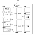
電子制御装置390は、図2に示すように、クロック発生回路390Aと、CPU(Central Processing Unit)390Bと、ROM(Read Only Memory)390Cと、RAM(Random Access Memory)390Dと、タイマカウンタ390Eと、出力回路390Fと、デジタル入力回路390Gと、アナログ入力回路390Hと、内部バス390Iと、入出力インタフェース(I/O)390Jと、変換回路390Kと、を内蔵している。
クロック発生回路390Aは、各回路の同期をとるためのクロックパルスを発生し、クロックパルスをCPU390Bに供給する。CPU390Bは、クロック発生回路390Aから供給されたクロックパルスに同期して、制御プログラムなどを読み込んで解釈及び実行することで、所要の目的を達成するためのデータを加工する。ROM390Cは、電源供給を遮断してもデータを保持可能な不揮発性メモリであって、制御プログラム、制御データ、学習値及び故障情報などを格納する。RAM390Dは、電源供給を遮断するとデータが消失する揮発性メモリであって、CPU390Bによる演算結果などを一時的に格納する。タイマカウンタ390Eは、制御に係る計時及び計数を行う。そして、CPU390B、ROM390C、RAM390D及びタイマカウンタ390Eは、内部バス390Iに夫々接続されている。
出力回路390Fは、外部機器などにアナログ信号又はデジタル信号を出力する出力ポートを提供する。デジタル入力回路390Gは、外部機器などからデジタル信号を受信する入力ポートを提供する。アナログ入力回路390Hは、外部機器などからアナログ信号を受信するための入力ポートを提供する。そして、出力回路390F及びデジタル入力回路390Gは、CPU390Bで処理可能な信号に変換又はCPU390Bの出力信号を外部機器などに適合した信号に変換する入出力インタフェース390Jを介して、内部バス390Iに接続されている。また、アナログ入力回路390Hは、アナログ信号をデジタル信号に変換するアナログ-デジタル変換機能及びアナログ信号を高速フーリエ変換する高速フーリエ変換(FFT;Fast Fourier Transform)機能を有する変換回路390Kを介して、内部バス390Iに接続されている。従って、CPU390B、ROM390C、RAM390D、タイマカウンタ390E、出力回路390F、デジタル入力回路390G及びアナログ入力回路390Hは、内部バス390Iを介して、任意のデータを送受信できるようになっている。
電子制御装置390は、ROM390Cに格納された各種の制御プログラムに従って、アイドル制御弁160、燃料噴射弁170、燃料ポンプ190及びイグニッションプラグ320を電子制御する。具体的には、電子制御装置390は、水温センサ370の出力信号及びエアコンディショナの作動状態などに応じて吸気流量を増量させる必要があるか否かを判定し、吸気流量を増量させる必要があると判定したときにアイドル制御弁160に作動信号を出力し、補助吸気通路120Aの開口面積を増加させる。また、電子制御装置390は、エアフローメータ150から出力された吸気流量信号及びクランク角センサ350から出力された回転数信号に応じた基本燃料噴射量を求める。そして、電子制御装置390は、水温センサ370、酸素濃度センサ270及び280などの出力信号に応じて基本燃料噴射量を適宜補正した燃料噴射量を求め、所定のタイミングで燃料噴射弁170に作動信号を出力し、その先端のノズルから燃料噴射量に応じた燃料を吸気ポートに噴射させる。このとき、電子制御装置390は、燃料噴射が完了した所定のタイミングでイグニッションプラグ320に作動信号を出力して混合気を着火させる。さらに、電子制御装置390は、燃料ポンプ190に作動信号を出力し、燃料ポンプ190により燃料タンク180に貯蔵されている燃料を燃料噴射弁170に供給させる。
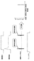
ここで、図3を参照し、燃料噴射弁170の開閉タイミングを検出する原理について説明する。
燃料噴射弁170は、上述したように、閉弁状態から開弁状態へと変化すると第1の所定周波数の振動が発生し、開弁状態から閉弁状態へと変化すると第2の所定周波数の振動が発生するという特性を有している。具体的には、図3に示すように、燃料噴射弁170の駆動電圧がローレベルからハイレベルに変化すると、燃料噴射弁170の駆動電流がフィードバック制御によって目標電流に収束する過程において、プランジャがストッパーに当たって第1の所定周波数の振動が発生する。また、燃料噴射弁170の駆動電圧がハイレベルからローレベルに変化すると、燃料噴射弁170の駆動電流が0まで低下する過程において、プランジャがバルブシートに当たって第2の所定周波数の振動が発生する。
燃料噴射弁170は、上述したように、閉弁状態から開弁状態へと変化すると第1の所定周波数の振動が発生し、開弁状態から閉弁状態へと変化すると第2の所定周波数の振動が発生するという特性を有している。具体的には、図3に示すように、燃料噴射弁170の駆動電圧がローレベルからハイレベルに変化すると、燃料噴射弁170の駆動電流がフィードバック制御によって目標電流に収束する過程において、プランジャがストッパーに当たって第1の所定周波数の振動が発生する。また、燃料噴射弁170の駆動電圧がハイレベルからローレベルに変化すると、燃料噴射弁170の駆動電流が0まで低下する過程において、プランジャがバルブシートに当たって第2の所定周波数の振動が発生する。
従って、振動をサンプリングする期間(開始タイミング~終了タイミング)を規定するウィンドウを導入し、このウィンドウによって規定された期間に振動をサンプリングする。そして、サンプリングされた振動を高速フーリエ変換(FFT)して周波数に変換し、その周波数のパワースペクトル(信号強度)を解析して、燃料噴射弁170の開閉タイミング、即ち、開弁タイミング及び閉弁タイミングを検出する。ここで、燃料圧力の変化によってパワースペクトルが低下するとパワースペクトルの解析が困難となるため、燃料噴射弁170の駆動電流を変化させてパワースペクトルを確保することで、燃料噴射弁170の開閉タイミングの検出精度を向上させることができる。
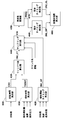
電子制御装置390のCPU390Bは、燃料噴射弁170の開閉タイミングを検出するために、ROM390Cに格納された制御プログラムに従って、図4に示すような各機能を実装する。なお、各機能を実装する前提として、電子制御装置390は、内燃機関100の運転状態に応じて、燃料噴射量及び点火時期の遅角状態をリアルタイムに算出しているものとする(以下同様)。
電子制御装置390は、各機能として、回転時間算出部400、噴射時間算出部410、噴射開始タイミング算出部420、ウィンドウ数算出部430、サンプリング実行部440、周波数変換部450、開弁タイミング検出部460、閉弁タイミング検出部470及び実噴射時間算出部480を実装している。
回転時間算出部400は、内燃機関100の回転数に基づいて、クランクシャフトが所定角度(例えば、1度)回転するのに要する回転時間CA1[μs/deg]を算出する。具体的には、回転時間算出部400は、回転数をNeとすると、「CA1=60000000/(Ne/360)」という式から回転時間CA1を算出する。なお、所定角度としては、1度に限らず、必要な検出精度などを考慮して、0.5度、1.5度、2度など任意の角度とすることができる。
噴射時間算出部410は、燃料噴射量、負荷及び燃料圧力に基づいて、燃料噴射弁170が燃料噴射量に相当する燃料を噴射するのに要する燃料噴射時間TIOUT[μs]を算出する。ここで、燃料圧力としては、プレッシャーレギュレータ210によって調整される所定の燃料圧力とすることができる。即ち、噴射時間算出部410は、負荷及び燃料圧力に応じて一定量の燃料を噴射するのに要する時間が変化することを考慮し、燃料噴射量に相当する燃料を噴射するのに要する燃料噴射時間TIOUTを算出する。なお、噴射時間算出部410は、少なくとも燃料噴射量及び燃料圧力に応じた燃料噴射時間TIOUTを算出すればよい。
噴射開始タイミング算出部420は、回転数、負荷及び点火時期の遅角状態に基づいて、燃料噴射弁170が燃料噴射を開始する燃料噴射開始タイミングINJ_ST[deg]を算出する。ここで、点火時期が遅角している場合には、燃焼ノイズが低減して周波数の検出精度が向上するため、点火時期の遅角状態をパラメータとして導入することで精度向上を図っている。従って、噴射開始タイミング算出部420は、パラメータの1つとして点火時期の遅角状態を用いずに、回転数及び負荷に基づいて燃料噴射開始タイミングINJ_STを算出するようにしてもよい。なお、燃料噴射開始タイミングINJ_STは、クランクシャフトの基準位置からの回転角[deg]として規定することができる(他のタイミングについても同様)。
ウィンドウ数算出部430は、回転時間CA1及び燃料噴射時間TIOUTに基づいて、燃料噴射弁170の開閉タイミングを検出するために必要な所定の固定幅を有するウィンドウの個数(ウィンドウ数)INJ_CTを算出する。具体的には、ウィンドウ数算出部430は、燃料噴射時間TIOUTを回転時間CA1で除算することで、ウィンドウ数INJ_CTを算出する。ここで、燃料噴射時間TIOUTを回転時間CA1で除算した値が小数点を有している場合、これを切り上げた整数値とすることができる。なお、固定幅は、例えば、燃料噴射弁170の噴射特性などを考慮して適宜決定することができる。
サンプリング実行部440は、クランク角が燃料噴射開始タイミングINJ_ST又はこれより進角側の所定タイミングになったとき、ウィンドウ1による振動のサンプリングを開始し、その後、所定角度ごとにウィンドウ2~INJ_CTによる振動のサンプリングを順次開始する。そして、サンプリング実行部440は、各ウィンドウ1~INJ_CTにおいて、内燃機関100の振動VIBをサンプリングする。
周波数変換部450は、変換回路390Kの機能を利用して、各ウィンドウ1~INJ_CTを使用してサンプリングされた振動VIBを周波数FREQ[Hz]に夫々変換し、その周波数FREQを各ウィンドウ1~INJ_CTに関連付ける。周波数FREQに変換された振動VIBは、図3に示すように、周波数とパワースペクトルとの関連を示す情報となる。従って、燃料噴射弁170が開弁又は閉弁したときには振動が発生するので、その振動に対応した周波数にパワースペクトルのピークが現れることとなる。
開弁タイミング検出部460は、各ウィンドウ1~INJ_CTに関連付けられた周波数FREQを順次参照して、開弁タイミングINJ_OPを検出する。なお、燃料噴射弁170の開弁タイミングの検出方法については、後述するフローチャートで詳細に説明する。
閉弁タイミング検出部470は、各ウィンドウ1~INJ_CTに関連付けられた周波数FREQを順次参照して、閉弁タイミングINJ_CLを検出する。なお、燃料噴射弁170の閉弁タイミングの検出方法については、後述するフローチャートで詳細に説明する。
実噴射時間算出部480は、燃料噴射弁170の閉弁タイミングINJ_CLからその開弁タイミングINJ_OPを減算することで、燃料噴射弁170が実際に燃料を噴射していた実燃料噴射時間[deg]を算出する。ここで、実燃料噴射時間は、クランクシャフトの角度ではなく、公知の手法によって変換した実噴射パルス幅としてもよい。
このようにすれば、電子制御装置390は、振動センサ380の出力信号から求められる振動パラメータと内燃機関100のクランクシャフトの回転角とに基づいて、燃料噴射弁170の開弁タイミング及び閉弁タイミングの少なくとも一方を検出することができる。このとき、燃料噴射弁170の開閉タイミングは、主に、内燃機関100に発生する振動によって検出されるため、燃料噴射量の大小による影響が少なく、燃料噴射弁170の開閉タイミングを高精度で検出することができる。従って、燃料のミキシング及び気化などを促進させるために燃料を複数回分割して噴射する分割噴射においても、燃料噴射弁170の開閉タイミングを高精度で検出することができる。なお、電子制御装置390の処理能力に余裕がある場合、ウィンドウ数INJ_CT及び燃料噴射開始タイミングINJ_STを算出せずに、クランクシャフトの所定回転ごとにウィンドウによる振動のサンプリングを順次実行するようにしてもよい。
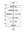
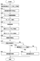
図5及び図6は、電子制御装置390が起動されたことを契機として、電子制御装置390のCPU390Bが所定時間ごとに繰り返し実行する、燃料噴射弁170の開閉タイミング検出処理の一例を示している。なお、図5及び図6に示す開閉タイミング検出処理においては、燃料噴射弁170の開閉タイミングの検出に加え、燃料噴射弁170の診断も行っている。
ステップ1(図では「S1」と略記する。以下同様。)では、CPU390Bが、クランク角センサ350から出力された回転数信号を読み込み、クランクシャフトが所定角度回転するのに要する回転時間CA1を算出する。なお、ステップ1の処理により、回転時間算出部400が実装される。
ステップ2では、CPU390Bが、負荷の一例として挙げることができる、エアフローメータ150から出力された吸気流量信号を読み込み、別処理により算出した燃料噴射量及び燃料圧力を考慮して、燃料噴射量に相当する燃料を燃料噴射弁170から噴射するのに要する燃料噴射時間TIOUTを算出する。ここで、負荷としては、吸気流量に限らず、スロットル開度センサ340により検出されたスロットルバルブ140の開度、アクセル開度、吸気負圧、過給圧力など、トルクと密接に関連する状態量とすることもできる。なお、ステップ2の処理により、噴射時間算出部410が実装される。
ステップ3では、CPU390Bが、エアフローメータ150から出力された吸気流量信号及びクランク角センサ350から出力された回転数信号を読み込み、別処理により算出した点火時期の遅角状態を考慮して、燃料噴射開始タイミングINJ_STを算出する。なお、ステップ3の処理により、噴射開始タイミング算出部420が実装される。
ステップ4では、CPU390Bが、回転時間CA1及び燃料噴射時間TIOUTに基づいて、ウィンドウ数INJ_CTを算出する。ここで、内燃機関100が所定回転数以上で作動している高回転時には、処理負荷を軽減するために、ウィンドウ数INJ_CTを減らしてもよい(以下同様)。なお、ステップ4の処理により、ウィンドウ数算出部430が実装される。
ステップ5では、CPU390Bが、クランク角センサ350から出力されたクランク角を読み込み、そのクランク角が燃料噴射開始タイミングINJ_ST又はこれより進角側の所定タイミングになったとき、ウィンドウ1による振動のサンプリングを開始し、その後、所定角度ごとにウィンドウ2~INJ_CTによる振動のサンプリングを順次開始する。そして、CPU390Bは、各ウィンドウ1~INJ_CTにおいて、振動センサ380から出力された振動を読み込んでサンプリングする。なお、ステップ5の処理により、サンプリング実行部440が実装される。
ステップ6では、CPU390Bが、変換回路390Kの機能を利用して、各ウィンドウ1~INJ_CTを使用してサンプリングされた振動を周波数に夫々変換する。ここで、CPU390Bは、変換回路390Kの機能を利用せずに、ソフトウエアによって振動を周波数に変換してもよい。なお、ステップ6の処理により、周波数変換部450が実装される。
ステップ7では、CPU390Bが、各ウィンドウ1~INJ_CTに関連付けられた周波数を順次参照し、燃料噴射弁170が開弁することにより発生する第1の所定周波数の振動が現れなくなったとき、その直前のウィンドウを使用したサンプリングの開始タイミングを開弁タイミングINJ_OPとして検出する。なお、ステップ7の処理により、開弁タイミング検出部460が実装される。
ステップ8では、CPU390Bが、各ウィンドウ1~INJ_CTに関連付けられた周波数を順次参照し、燃料噴射弁170が閉弁することにより発生する第2の所定周波数の振動が現れたとき、そのウィンドウを使用したサンプリングの開始タイミングを閉弁タイミングINJ_CLとして検出する。なお、ステップ8の処理により、閉弁タイミング検出部470が実装される。
ステップ9では、CPU390Bが、燃料噴射弁170の閉弁タイミングINJ_CLから開弁タイミングINJ_OPを減算することで、燃料噴射弁170が実際に燃料を噴射していた実燃料噴射時間を算出する。なお、ステップ9の処理により、実噴射時間算出部480が実装される。
ステップ10では、CPU390Bが、ステップ9で算出した実燃料噴射時間とステップ2で算出した燃料噴射時間TIOUT(指示燃料噴射時間)とを比較して、実燃料噴射時間が異常であるか否かを判定する。具体的には、CPU390Bは、実燃料噴射時間が燃料噴射時間TIOUTから所定時間以上逸脱しているか否かを介して、実燃料噴射時間が異常であるか否かを判定する。そして、CPU390Bは、実燃料噴射時間が異常であると判定したならば(Yes)、処理をステップ12へと進める。一方、CPU390Bは、実燃料噴射時間が異常でない、即ち、実燃料噴射時間が正常であると判定したならば(No)、処理をステップ11へと進める。
ステップ11では、CPU390Bが、ステップ7で検出した開弁タイミングINJ_OPにより特定される燃料噴射開始タイミングとステップ3で算出した燃料噴射開始タイミングINJ_ST(指示噴射開始タイミング)とを比較して、燃料噴射開始タイミングが異常であるか否かを判定する。具体的には、CPU390Bは、開弁タイミングINJ_OPにより特定される燃料噴射開始タイミングが燃料噴射開始タイミングINJ_STより所定角度以上逸脱しているか否かを介して、噴射開始タイミングが異常であるか否かを判定する。そして、CPU390Bは、燃料噴射開始タイミングが異常であると判定したならば(Yes)、処理をステップ12へと進める。一方、CPU390Bは、燃料噴射開始タイミングが異常でない、即ち、燃料噴射開始タイミングが正常であると判定したならば(No)、処理をステップ13へと進める。
ステップ12では、CPU390Bが、燃料噴射弁170が異常であると判定する。燃料噴射弁170が異常であると判定された場合、CPU390Bは、これを運転者などに報知すべくMIL(Malfunction Indicator Lamp)を点灯したり、故障情報などをROM390Cに格納したりすることができる。
ステップ13では、CPU390Bが、燃料噴射弁170が正常であると判定する。
ステップ13では、CPU390Bが、燃料噴射弁170が正常であると判定する。
要するに、電子制御装置390のCPU390Bは、振動センサ380の出力信号をサンプリングする期間を規定するウィンドウを使用し、燃料噴射弁170の燃料噴射開始タイミングINJ_ST又はこれより進角側の所定タイミングから遅角側へと向かって徐々にずらしながら、振動センサ380の出力信号を複数回サンプリングして周波数変換する。そして、電子制御装置390のCPU390Bは、所定周波数(第1の所定周波数及び第2の所定周波数)における周波数の信号強度(パワースペクトル)とサンプリングの開始タイミングとに基づいて、燃料噴射弁170の開弁タイミング及び閉弁タイミングの少なくとも一方を検出する。
また、電子制御装置390のCPU390Bは、燃料噴射弁170の開弁タイミングINJ_OPと燃料噴射開始タイミングINJ_STとを比較して、燃料噴射弁170が正常に作動しているか否かを診断する。さらに、電子制御装置390のCPU390Bは、燃料噴射弁170の開弁タイミング及び閉弁タイミングにより求められる実燃料噴射時間と燃料噴射時間TIOUTとを比較して、燃料噴射弁170が正常に作動しているか否かを診断する。
図5及び図6に示す開閉タイミング検出処理において、電子制御装置390のCPU390Bは、所定周波数におけるパワースペクトルが所定レベル以下である場合、燃料噴射弁170に異常があると判定することができる。また、電子制御装置390のCPU390Bは、振動センサ380に異常があるか、又は、所定周波数におけるパワースペクトルが所定レベルより小さい許容レベル未満である場合、燃料噴射弁170が正常に作動しているか否かの診断を中止することもできる。
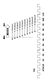
ここで、燃料噴射弁170の開閉タイミングの検出方法について、その理解を容易ならしめることを目的として、図7に示すような具体的な一例を挙げて説明する。この一例においては、燃料噴射弁170は上死点(TDC)から65度で開弁して90度で閉弁するものとする。また、15度の固定幅を有するウィンドウが10個あり(ウィンドウ1~10)、各ウィンドウは、上死点から61度でウィンドウ1を使用したサンプリングを開始し、その後、2度ごとウィンドウ2~10を使用したサンプリングを順次開始するものとする。
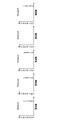
ウィンドウ1は、上死点から61度~76度の範囲で振動をサンプリングする。燃料噴射弁170は上死点から65度で開弁するため、ウィンドウ1を使用した振動のサンプリング結果には、図8に示すように、燃料噴射弁170の開弁により発生する第1の所定周波数の振動が現れる。ウィンドウ2は、上死点から63度~78度の範囲で振動をサンプリングする。燃料噴射弁170は上死点から65度で開弁するため、ウィンドウ2を使用した振動のサンプリング結果には、図8に示すように、燃料噴射弁170の開弁により発生する第1の所定周波数の振動が現れる。ウィンドウ3は、上死点から65度~80度の範囲で振動をサンプリングする。燃料噴射弁170は上死点から65度で開弁するため、ウィンドウ3を使用した振動のサンプリング結果には、図8に示すように、燃料噴射弁170の開弁により発生する第1の所定周波数の振動が現れる。
ウィンドウ4は、上死点から67度~82度の範囲で振動をサンプリングする。燃料噴射弁170は上死点から65度で開弁して90度で閉弁するため、ウィンドウ4を使用した振動のサンプリング結果には、図8に示すように、燃料噴射弁170の開弁又は閉弁により発生する第1の所定周波数又は第2の所定周波数の振動が現れない。従って、開弁による振動が現れなくなったウィンドウ4の直前のウィンドウ3を使用したサンプリングの開始タイミングは、燃料噴射弁170の開弁タイミングINJ_OPであると見做すことができる。
その後、ウィンドウ5~ウィンドウ8による振動のサンプリング結果においても、ウィンドウ4と同様に、燃料噴射弁170の開弁又は閉弁により発生する第1の所定周波数又は第2の所定周波数の振動が現れない。ウィンドウ9は、上死点から75度~90度の範囲で振動をサンプリングする。燃料噴射弁170は上死点から90度で閉弁するため、ウィンドウ9を使用した振動のサンプリング結果には、図8に示すように、燃料噴射弁170の閉弁により発生する第2の所定周波数の振動が現れる。従って、閉弁による振動が現れたウィンドウ9のサンプリング開始タイミングは、燃料噴射弁170の閉弁タイミングINJ_CLであると見做すことができる。
電子制御装置390のCPU390Bは、燃料噴射弁170の開閉タイミングを検出するために、ROM390Cに格納された制御プログラムに従って、図9に示すような各機能を実装することもできる。
電子制御装置390は、各機能として、噴射開始タイミング算出部500、噴射時間算出部510、ウィンドウ幅算出部520、サンプリング実行部530、周波数変換部540、開弁タイミング検出部550、閉弁タイミング検出部560及び実噴射時間算出部570を実装している。なお、図4に示す機能と同様である機能については、重複説明を排除するために、その説明を簡単にすることとする。必要があれば、先の実施形態の説明を参照されたい。
噴射開始タイミング算出部500は、回転数、負荷及び点火時期の遅角状態に基づいて、燃料噴射弁170が燃料噴射を開始する燃料噴射開始タイミングINJ_ST[deg]を算出する。
噴射時間算出部510は、燃料噴射量、回転数、負荷、水温、吸気温及び燃料圧力に基づいて、燃料噴射弁170が燃料噴射量に相当する燃料を噴射するのに要する燃料噴射時間TIOUT[μs]を算出する。即ち、噴射時間算出部510は、回転数、負荷、水温、吸気温及び燃料圧力に応じて一定量の燃料を噴射するのに要する時間が変化することを考慮し、燃料噴射量に相当する燃料を噴射するのに要する燃料噴射時間TIOUTを算出する。なお、噴射時間算出部510は、少なくとも燃料噴射量及び燃料圧力に応じた燃料噴射時間TIOUTを算出すればよい。
ウィンドウ幅算出部520は、燃料噴射時間TIOUTに基づいて、燃料噴射弁170の開閉タイミングを検出するために必要なウィンドウの可変幅(ウィンドウ幅)WIDTH[deg]を算出する。具体的には、ウィンドウ幅算出部520は、燃料噴射時間TIOUTをウィンドウ幅WIDTHとして算出する。このようにすれば、ウィンドウ幅WIDTHを有するウィンドウを使用した振動のサンプリングを適切なタイミングで開始すると、1つのウィンドウによって燃料噴射弁170の開弁及び閉弁によって発生する第1の所定周波数及び第2の所定周波数の振動を検出することができる。
サンプリング実行部530は、クランク角が燃料噴射開始タイミングINJ_ST又はこれより進角側の所定タイミングになったとき、ウィンドウ1を使用した振動のサンプリングを開始し、その後、検出精度などを考慮して決定された所定角度ごとにウィンドウ2~N(N:3以上の自然数)を使用した振動のサンプリングを順次開始する。ここで、振動をサンプリングするために使用するウィンドウの数Nは、先の実施形態とは異なり、任意の固定数とすることができる。そして、サンプリング実行部530は、各ウィンドウ1~Nにおいて、内燃機関100の振動VIBをサンプリングする。
周波数変換部540は、変換回路390Kの機能を利用して、各ウィンドウ1~Nを使用してサンプリングされた振動VIBを周波数FREQ[Hz]に夫々変換し、その周波数FREQを各ウィンドウ1~Nに関連付ける。
開弁タイミング検出部550は、各ウィンドウ1~Nに関連付けられた周波数FREQを順次参照して、開弁タイミングINJ_OPを検出する。なお、燃料噴射弁170の開弁タイミングの検出方法については、後述するフローチャートで詳細に説明する。
閉弁タイミング検出部560は、各ウィンドウ1~Nに関連付けられた周波数FREQを順次参照して、閉弁タイミングINJ_CLを検出する。なお、燃料噴射弁170の閉弁タイミングの検出方法については、後述するフローチャートで詳細に説明する。
実噴射時間算出部570は、燃料噴射弁170の閉弁タイミングINJ_CLから開弁タイミングINJ_OPを減算することで、燃料噴射弁170が実際に燃料を噴射していた実燃料噴射時間[deg]を算出する。
このようにすれば、電子制御装置390は、先の実施形態と同様に、振動センサ380の出力信号から求められる振動パラメータと内燃機関100のクランクシャフトの回転角とに基づいて、燃料噴射弁170の開弁タイミング及び閉弁タイミングの少なくとも一方を検出することができる。このとき、振動をサンプリングするために使用するウィンドウのウィンドウ幅WIDTHは、燃料噴射時間TIOUTに応じて動的に変更されるため、振動をサンプリングするためのウィンドウの数を減らすことができ、例えば、電子制御装置390の処理負荷を軽減することができる。なお、他の作用及び効果については、先の実施形態と同様であるので、その詳細な説明を省略する。必要があれば、先の実施形態の説明を参照されたい。
図10は、電子制御装置390が起動されたことを契機として、電子制御装置390のCPU390Bが所定時間ごとに繰り返し実行する、燃料噴射弁170の開閉タイミング検出処理の他の例を示している。図10に示す開閉タイミング検出処理においては、先の実施形態と同様に、燃料噴射弁170の開閉タイミングの検出に加え、燃料噴射弁170の診断も行っている。なお、先の実施形態と同様な処理については、重複説明を排除するために、その説明を簡単にする。必要があれば、先の実施形態の説明を参照されたい。
ステップ21では、CPU390Bが、負荷の一例として挙げることができるエアフローメータ150から出力された吸気流量、及びクランク角センサ350から出力された回転数信号を読み込み、別処理により算出した点火時期の遅角状態を考慮して、燃料噴射開始タイミングINJ_STを算出する。なお、ステップ21の処理により、噴射開始タイミング算出部500が実装される。
ステップ22では、CPU390Bが、エアフローメータ150から出力された吸気流量信号及び吸気温信号、クランク角センサ350から出力された回転数信号、並びに水温センサ370から出力された水温信号を読み込み、別処理により算出した燃料噴射量及び燃料圧力を考慮して、燃料噴射量に相当する燃料を燃料噴射弁170から噴射するのに要する燃料噴射時間TIOUTを算出する。なお、ステップ22の処理により、噴射時間算出部510が実装される。
ステップ23では、CPU390Bが、燃料噴射時間TIOUTに基づいて、燃料噴射弁170の開閉タイミングを検出するために必要なウィンドウ幅WIDTHを算出する。なお、ステップ23の処理により、ウィンドウ幅算出部520が実装される。
ステップ24では、CPU390Bが、クランク角センサ350から出力されたクランク角を読み込み、そのクランク角が燃料噴射開始タイミングINJ_ST又はこれより進角側の所定タイミングになったとき、ウィンドウ1を使用した振動のサンプリングを開始し、その後、所定角度ごとにウィンドウ2~Nを使用した振動のサンプリングを順次開始する。そして、CPU390Bは、各ウィンドウ1~Nにおいて、振動センサ380から出力された振動VIBを読み込んでサンプリングする。なお、ステップ24の処理により、サンプリング実行部530が実装される。
ステップ25では、CPU390Bが、変換回路390Kの機能を利用して、各ウィンドウ1~Nを使用してサンプリングされた振動VIBを周波数FREQに夫々変換する。なお、ステップ25の処理により、周波数変換部540が実装される。
ステップ26では、CPU390Bが、各ウィンドウ1~Nに関連付けられた周波数FREQを順次参照し、特定のウィンドウを使用した振動のサンプリング結果に燃料噴射弁170が開弁及び閉弁することにより発生する第1の所定周波数及び第2の所定周波数の振動が共に現れたとき、そのウィンドウを使用したサンプリングの開始タイミングを開弁タイミングINJ_OPとして検出する。なお、ステップ26の処理により、開弁タイミング検出部550が実装される。
ステップ27では、CPU390Bが、各ウィンドウ1~Nに関連付けられた周波数FREQを順次参照し、特定のウィンドウを使用した振動のサンプリング結果に燃料噴射弁170が開弁及び閉弁することにより発生する第1の所定周波数及び第2の所定周波数の振動が共に現れたとき、そのウィンドウを使用したサンプリングの終了タイミングを閉弁タイミングINJ_CLとして検出する。なお、ステップ27の処理により、閉弁タイミング検出部560が実装される。
ステップ28では、CPU390Bが、燃料噴射弁170の閉弁タイミングINJ_CLから開弁タイミングINJ_OPを減算することで、燃料噴射弁170が実際に燃料を噴射していた実燃料噴射時間を算出する。ここで、CPU390Bは、ステップ22で算出した燃料噴射時間TIOUTを実燃料噴射時間とすることもできる。なお、ステップ28の処理により、実噴射時間算出部570が実装される。
ステップ29では、CPU390Bが、ステップ28で算出した実燃料噴射時間とステップ22で算出した燃料噴射時間TIOUT(指示燃料噴射時間)とを比較して、実燃料噴射時間が異常であるか否かを判定する。具体的には、CPU390Bは、実燃料噴射時間が燃料噴射時間TIOUTより所定時間以上逸脱しているか否かを介して、実燃料噴射時間が異常であるか否かを判定する。そして、CPU390Bは、実燃料噴射時間が異常であると判定したならば(Yes)、処理をステップ31へと進める。一方、CPU390Bは、実燃料噴射時間が異常でない、即ち、実燃料噴射時間が正常であると判定したならば(No)、処理をステップ30へと進める。
ステップ30では、CPU390Bが、ステップ26で検出した開弁タイミングINJ_OPにより特定される燃料噴射開始タイミングとステップ21で算出した燃料噴射開始タイミングINJ_ST(指示噴射開始タイミング)とを比較して、燃料噴射開始タイミングが異常であるか否かを判定する。具体的には、CPU390Bは、開弁タイミングINJ_OPにより特定される燃料噴射開始タイミングが燃料噴射開始タイミングINJ_STより所定角度以上逸脱しているか否かを介して、燃料噴射開始タイミングが異常であるか否かを判定する。そして、CPU390Bは、燃料噴射開始タイミングが異常であると判定したならば(Yes)、処理をステップ31へと進める。一方、CPU390Bは、燃料噴射開始タイミングが異常でない、即ち、燃料噴射開始タイミングが正常であると判定したならば(No)、処理をステップ32へと進める。
ステップ31では、CPU390Bが、燃料噴射弁170が異常であると判定する。燃料噴射弁170が異常であると判定された場合、CPU390Bは、これを運転者などに報知すべくMILを点灯したり、故障情報などをROM390Cに格納したりすることができる。
ステップ32では、CPU390Bが、燃料噴射弁170が正常であると判定する。
ステップ32では、CPU390Bが、燃料噴射弁170が正常であると判定する。
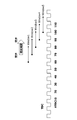
ここで、燃料噴射弁170の開閉タイミングの検出方法について、その理解を容易ならしめることを目的として、図11に示すような具体的な一例を挙げて説明する。この一例においては、燃料噴射弁170は上死点から70度で開弁して90度で閉弁するものとする。また、20度の可変幅を有するウィンドウが5個あり(ウィンドウ1~5)、各ウィンドウは、上死点から60度でウィンドウ1を使用したサンプリングを開始し、その後、10度ごとにウィンドウ2~5を使用したサンプリングを順次開始するものとする。
ウィンドウ1は、上死点から60度~80度の範囲で振動をサンプリングする。燃料噴射弁170は上死点から70度で開弁して90度で閉弁するため、ウィンドウ1を使用した振動のサンプリング結果には、図12に示すように、燃料噴射弁170の開弁により発生する第1の所定周波数の振動のみが現れる。ウィンドウ2は、上死点から70度~90度の範囲で振動をサンプリングする。燃料噴射弁170は上死点から70度で開弁して90度で閉弁するため、ウィンドウ2を使用した振動のサンプリング結果には、図12に示すように、燃料噴射弁170の開弁及び閉弁により発生する第1の所定周波数の振動及び第2の所定周波数の振動が共に現れる。
従って、開弁及び閉弁による振動が共に現れたウィンドウ2を使用したサンプリングにおいて、そのサンプリング開始タイミング(70度)が燃料噴射弁170の開弁タイミングINJ_OP、そのサンプリング終了タイミング(90度)が燃料噴射弁170の閉弁タイミングINJ_CLであると見做すことができる。
ウィンドウ3は、上死点から80度~100度の範囲で振動をサンプリングする。燃料噴射弁170は上死点から70度で開弁して90度で閉弁するため、ウィンドウ3を使用した振動のサンプリング結果には、図12に示すように、燃料噴射弁170の閉弁により発生する第2の所定周波数の振動のみが現れる。ウィンドウ4は、上死点から90度~110度の範囲で振動をサンプリングする。燃料噴射弁170は上死点から70度で開弁して90度で閉弁するため、ウィンドウ4を使用した振動のサンプリング結果には、図12に示すように、ウィンドウ3と同様に、燃料噴射弁170の閉弁により発生する第2の所定周波数の振動のみが現れる。ウィンドウ5は、上死点から100度~120度の範囲で振動をサンプリングする。燃料噴射弁170は上死点から70度で開弁して90度で閉弁するため、ウィンドウ5を使用した振動のサンプリング結果には、図12に示すように、燃料噴射弁170の開弁及び閉弁により発生する第1の所定周波数の振動及び第2の所定周波数の振動が共に現れない。
要するに、少なくとも燃料噴射量及び燃料圧力に応じたウィンドウ幅WIDTHを有するウィンドウを使用し、そのウィンドウによる振動のサンプリング結果に燃料噴射弁170の開弁及び閉弁により発生する2つの振動が現れているか否かに応じて、燃料噴射弁170の開閉タイミングを検出することができる。
なお、当業者であれば、様々な上記実施形態の技術的思想について、その一部を省略したり、その一部を適宜組み合わせたり、その一部を置換したりすることで、新たな実施形態を生み出せることを容易に理解できるであろう。
100 内燃機関
170 燃料噴射弁
350 クランク角センサ
380 振動センサ
390 電子制御装置
170 燃料噴射弁
350 クランク角センサ
380 振動センサ
390 電子制御装置
Claims (16)
- 内燃機関の振動を検出する振動センサの出力信号を読み込み可能な燃料噴射弁の作動検出装置であって、
前記振動センサの出力信号から求められる振動パラメータと前記内燃機関の回転角とに基づいて、前記燃料噴射弁の開弁タイミング及び閉弁タイミングの少なくとも一方を検出する、
燃料噴射弁の作動検出装置。 - 前記燃料噴射弁の燃料噴射開始タイミング又はこれより進角側の所定タイミングから遅角側へと向かって、前記振動センサの出力信号を所定期間に亘ってサンプリングして周波数変換し、所定周波数における周波数の信号強度と前記サンプリングの開始タイミングとに基づいて、前記燃料噴射弁の開弁タイミング及び閉弁タイミングの少なくとも一方を検出する、
請求項1に記載の燃料噴射弁の作動検出装置。 - 前記サンプリングは、前記燃料噴射開始タイミング又は前記所定タイミングから遅角側へと向かって徐々にずらしながら複数回実行される、
請求項2に記載の燃料噴射弁の作動検出装置。 - 前記検出された開弁タイミングと前記燃料噴射弁への指示噴射開始タイミングとを比較して、前記燃料噴射弁が正常に作動しているか否かを診断する、
請求項1に記載の燃料噴射弁の作動検出装置。 - 前記検出された開弁タイミング及び閉弁タイミングにより求められる実燃料噴射時間と前記燃料噴射弁への指示燃料噴射時間とを比較して、前記燃料噴射弁が正常に作動しているか否かを診断する、
請求項1に記載の燃料噴射弁の作動検出装置。 - 前記所定周波数における信号強度が所定レベル以下である場合、前記燃料噴射弁に異常があると判定する、
請求項2に記載の燃料噴射弁の作動検出装置。 - 前記振動センサに異常、又は前記所定周波数における信号強度が前記所定レベルより小さい許容レベル未満である場合、前記燃料噴射弁が正常に作動しているか否かの診断を中止する、
請求項6に記載の燃料噴射弁の作動検出装置。 - 前記燃料噴射弁の駆動電流を変化させて前記振動パラメータを確保する、
請求項1に記載の燃料噴射弁の作動検出装置。 - 内燃機関の振動を検出する振動センサの出力信号を読み込み可能な電子制御装置が、前記振動センサの出力信号から求められる振動パラメータと前記内燃機関の回転角とに基づいて、燃料噴射弁の開弁タイミング及び閉弁タイミングの少なくとも一方を検出する、
燃料噴射弁の作動検出方法。 - 前記電子制御装置が、前記燃料噴射弁の燃料噴射開始タイミング又はこれより進角側の所定タイミングから遅角側へと向かって、前記振動センサの出力信号を所定期間に亘ってサンプリングして周波数変換し、所定周波数における周波数の信号強度と前記サンプリングの開始タイミングとに基づいて、前記燃料噴射弁の開弁タイミング及び閉弁タイミングの少なくとも一方を検出する、
請求項9に記載の燃料噴射弁の作動検出方法。 - 前記電子制御装置が、前記燃料噴射開始タイミング又は前記所定タイミングから遅角側へと向かって徐々にずらしながら前記サンプリングを複数回実行する、
請求項10に記載の燃料噴射弁の作動検出方法。 - 前記電子制御装置が、前記検出された開弁タイミングと前記燃料噴射弁への指示噴射開始タイミングとを比較して、前記燃料噴射弁が正常に作動しているか否かを診断する、
請求項9に記載の燃料噴射弁の作動検出方法。 - 前記電子制御装置が、前記検出された開弁タイミング及び閉弁タイミングにより求められる実燃料噴射時間と前記燃料噴射弁への指示燃料噴射時間とを比較して、前記燃料噴射弁が正常に作動しているか否かを診断する、
請求項9に記載の燃料噴射弁の作動検出方法。 - 前記電子制御装置が、前記所定周波数における信号強度が所定レベル以下である場合、前記燃料噴射弁に異常があると判定する、
請求項10に記載の燃料噴射弁の作動検出方法。 - 前記電子制御装置が、前記振動センサに異常、又は前記所定周波数における信号強度が前記所定レベルより小さい許容レベル未満である場合、前記燃料噴射弁が正常に作動しているか否かの診断を中止する、
請求項14に記載の燃料噴射弁の作動検出方法。 - 前記電子制御装置が、前記燃料噴射弁の駆動電流を変化させて前記振動パラメータを確保する、
請求項9に記載の燃料噴射弁の作動検出方法。
Applications Claiming Priority (2)
| Application Number | Priority Date | Filing Date | Title |
|---|---|---|---|
| JP2019-042765 | 2019-03-08 | ||
| JP2019042765A JP2020143651A (ja) | 2019-03-08 | 2019-03-08 | 燃料噴射弁の作動検出装置及び作動検出方法 |
Publications (1)
| Publication Number | Publication Date |
|---|---|
| WO2020184370A1 true WO2020184370A1 (ja) | 2020-09-17 |
Family
ID=72353854
Family Applications (1)
| Application Number | Title | Priority Date | Filing Date |
|---|---|---|---|
| PCT/JP2020/009368 Ceased WO2020184370A1 (ja) | 2019-03-08 | 2020-03-05 | 燃料噴射弁の作動検出装置及び作動検出方法 |
Country Status (2)
| Country | Link |
|---|---|
| JP (1) | JP2020143651A (ja) |
| WO (1) | WO2020184370A1 (ja) |
Citations (3)
| Publication number | Priority date | Publication date | Assignee | Title |
|---|---|---|---|---|
| JPH10318027A (ja) * | 1997-05-15 | 1998-12-02 | Nippon Soken Inc | 内燃機関の燃料噴射弁異常検出装置 |
| JP2000348668A (ja) * | 1999-06-08 | 2000-12-15 | Jeol Ltd | 飛行時間型質量分析装置用データ収集方法 |
| JP2013171010A (ja) * | 2012-02-23 | 2013-09-02 | Furukawa Electric Co Ltd:The | レーダ装置およびレーダ装置の演算方法 |
-
2019
- 2019-03-08 JP JP2019042765A patent/JP2020143651A/ja not_active Withdrawn
-
2020
- 2020-03-05 WO PCT/JP2020/009368 patent/WO2020184370A1/ja not_active Ceased
Patent Citations (3)
| Publication number | Priority date | Publication date | Assignee | Title |
|---|---|---|---|---|
| JPH10318027A (ja) * | 1997-05-15 | 1998-12-02 | Nippon Soken Inc | 内燃機関の燃料噴射弁異常検出装置 |
| JP2000348668A (ja) * | 1999-06-08 | 2000-12-15 | Jeol Ltd | 飛行時間型質量分析装置用データ収集方法 |
| JP2013171010A (ja) * | 2012-02-23 | 2013-09-02 | Furukawa Electric Co Ltd:The | レーダ装置およびレーダ装置の演算方法 |
Also Published As
| Publication number | Publication date |
|---|---|
| JP2020143651A (ja) | 2020-09-10 |
Similar Documents
| Publication | Publication Date | Title |
|---|---|---|
| US9175627B2 (en) | Fuel injection control apparatus for an internal combustion engine | |
| JP2011185159A (ja) | 過給機付き内燃機関の異常診断装置 | |
| CN103547783B (zh) | 内燃机的空燃比失衡检测装置 | |
| JPH03164537A (ja) | 内燃機関のバルブタイミング制御装置 | |
| US20130197786A1 (en) | Control apparatus and control method for multi-cylinder internal combustion engine | |
| US20070084442A1 (en) | Engine combustion state determining apparatus and method | |
| JPH0215010B2 (ja) | ||
| JPH04214947A (ja) | 内燃機関のトルク変動制御装置 | |
| JP2017002878A (ja) | 内燃機関の制御装置 | |
| JPH04187845A (ja) | 多種燃料内燃エンジンの空燃比フィードバック制御方法 | |
| US9404431B2 (en) | Method and device for operating an internal combustion engine | |
| US9217384B2 (en) | Diagnosis method and device for operating an internal combustion engine | |
| US10337437B2 (en) | Abnormality diagnosis device and abnormality diagnosis method for internal combustion engine | |
| JP2012112253A (ja) | エンジン制御装置 | |
| JP2007231883A (ja) | 内燃機関の空燃比制御装置 | |
| JP3959781B2 (ja) | 直噴式火花点火機関の失火検出装置及び制御装置 | |
| JP2009191650A (ja) | 内燃機関の制御装置 | |
| JP5187537B2 (ja) | 内燃機関の燃料噴射制御装置 | |
| JP2020143651A (ja) | 燃料噴射弁の作動検出装置及び作動検出方法 | |
| JP2013015105A (ja) | 内燃機関のノック判定装置 | |
| JP7575873B2 (ja) | 点火制御式内燃エンジンにおけるリッチネスを調整する方法 | |
| JP7758583B2 (ja) | エンジンの制御装置 | |
| Burkhard | Individual cylinder fuel control for a turbocharged engine | |
| JP7614909B2 (ja) | エンジン制御システム | |
| US20260139637A1 (en) | Control device for internal combustion engine |
Legal Events
| Date | Code | Title | Description |
|---|---|---|---|
| 121 | Ep: the epo has been informed by wipo that ep was designated in this application |
Ref document number: 20770449 Country of ref document: EP Kind code of ref document: A1 |
|
| NENP | Non-entry into the national phase |
Ref country code: DE |
|
| 122 | Ep: pct application non-entry in european phase |
Ref document number: 20770449 Country of ref document: EP Kind code of ref document: A1 |