WO2020184265A1 - 画像復号装置、画像復号方法及びプログラム - Google Patents
画像復号装置、画像復号方法及びプログラム Download PDFInfo
- Publication number
- WO2020184265A1 WO2020184265A1 PCT/JP2020/008775 JP2020008775W WO2020184265A1 WO 2020184265 A1 WO2020184265 A1 WO 2020184265A1 JP 2020008775 W JP2020008775 W JP 2020008775W WO 2020184265 A1 WO2020184265 A1 WO 2020184265A1
- Authority
- WO
- WIPO (PCT)
- Prior art keywords
- prediction
- mode
- intra
- subdivision
- identification flag
- Prior art date
- Legal status (The legal status is an assumption and is not a legal conclusion. Google has not performed a legal analysis and makes no representation as to the accuracy of the status listed.)
- Ceased
Links
Images








Classifications
-
- H—ELECTRICITY
- H04—ELECTRIC COMMUNICATION TECHNIQUE
- H04N—PICTORIAL COMMUNICATION, e.g. TELEVISION
- H04N19/00—Methods or arrangements for coding, decoding, compressing or decompressing digital video signals
- H04N19/10—Methods or arrangements for coding, decoding, compressing or decompressing digital video signals using adaptive coding
- H04N19/102—Methods or arrangements for coding, decoding, compressing or decompressing digital video signals using adaptive coding characterised by the element, parameter or selection affected or controlled by the adaptive coding
- H04N19/103—Selection of coding mode or of prediction mode
- H04N19/11—Selection of coding mode or of prediction mode among a plurality of spatial predictive coding modes
-
- H—ELECTRICITY
- H04—ELECTRIC COMMUNICATION TECHNIQUE
- H04N—PICTORIAL COMMUNICATION, e.g. TELEVISION
- H04N19/00—Methods or arrangements for coding, decoding, compressing or decompressing digital video signals
- H04N19/10—Methods or arrangements for coding, decoding, compressing or decompressing digital video signals using adaptive coding
- H04N19/134—Methods or arrangements for coding, decoding, compressing or decompressing digital video signals using adaptive coding characterised by the element, parameter or criterion affecting or controlling the adaptive coding
- H04N19/136—Incoming video signal characteristics or properties
-
- H—ELECTRICITY
- H04—ELECTRIC COMMUNICATION TECHNIQUE
- H04N—PICTORIAL COMMUNICATION, e.g. TELEVISION
- H04N19/00—Methods or arrangements for coding, decoding, compressing or decompressing digital video signals
- H04N19/10—Methods or arrangements for coding, decoding, compressing or decompressing digital video signals using adaptive coding
- H04N19/134—Methods or arrangements for coding, decoding, compressing or decompressing digital video signals using adaptive coding characterised by the element, parameter or criterion affecting or controlling the adaptive coding
- H04N19/157—Assigned coding mode, i.e. the coding mode being predefined or preselected to be further used for selection of another element or parameter
-
- H—ELECTRICITY
- H04—ELECTRIC COMMUNICATION TECHNIQUE
- H04N—PICTORIAL COMMUNICATION, e.g. TELEVISION
- H04N19/00—Methods or arrangements for coding, decoding, compressing or decompressing digital video signals
- H04N19/10—Methods or arrangements for coding, decoding, compressing or decompressing digital video signals using adaptive coding
- H04N19/169—Methods or arrangements for coding, decoding, compressing or decompressing digital video signals using adaptive coding characterised by the coding unit, i.e. the structural portion or semantic portion of the video signal being the object or the subject of the adaptive coding
- H04N19/17—Methods or arrangements for coding, decoding, compressing or decompressing digital video signals using adaptive coding characterised by the coding unit, i.e. the structural portion or semantic portion of the video signal being the object or the subject of the adaptive coding the unit being an image region, e.g. an object
- H04N19/176—Methods or arrangements for coding, decoding, compressing or decompressing digital video signals using adaptive coding characterised by the coding unit, i.e. the structural portion or semantic portion of the video signal being the object or the subject of the adaptive coding the unit being an image region, e.g. an object the region being a block, e.g. a macroblock
-
- H—ELECTRICITY
- H04—ELECTRIC COMMUNICATION TECHNIQUE
- H04N—PICTORIAL COMMUNICATION, e.g. TELEVISION
- H04N19/00—Methods or arrangements for coding, decoding, compressing or decompressing digital video signals
- H04N19/46—Embedding additional information in the video signal during the compression process
-
- H—ELECTRICITY
- H04—ELECTRIC COMMUNICATION TECHNIQUE
- H04N—PICTORIAL COMMUNICATION, e.g. TELEVISION
- H04N19/00—Methods or arrangements for coding, decoding, compressing or decompressing digital video signals
- H04N19/50—Methods or arrangements for coding, decoding, compressing or decompressing digital video signals using predictive coding
- H04N19/593—Methods or arrangements for coding, decoding, compressing or decompressing digital video signals using predictive coding involving spatial prediction techniques
-
- H—ELECTRICITY
- H04—ELECTRIC COMMUNICATION TECHNIQUE
- H04N—PICTORIAL COMMUNICATION, e.g. TELEVISION
- H04N19/00—Methods or arrangements for coding, decoding, compressing or decompressing digital video signals
- H04N19/70—Methods or arrangements for coding, decoding, compressing or decompressing digital video signals characterised by syntax aspects related to video coding, e.g. related to compression standards
Definitions
- the present invention relates to an image decoding device, an image decoding method, and a program.
- Non-Patent Document 1 discloses a method for decoding a prediction mode for an intra-prediction method, and describes a method for decoding a prediction mode using a total of three methods for constructing a maximum likelihood mode (MPM: Most Problem Mode) list. ing.
- MPM Most Problem Mode
- Non-Patent Document 2 discloses a technique called multiple reference line prediction (MRL: Multi-Reference-Line prediction).
- MRL is a kind of intra prediction method
- the reference pixel used at the time of generating the prediction pixel is the closest pixel adjacent to the prediction target block (0th line), or is adjacent to the prediction target block. This is a technique for improving prediction performance by adaptively switching whether to use adjacent pixels that are one or more lines away from the closest pixel.
- Non-Patent Document 3 discloses a technique called intra-sub-partitions prediction (ISP).
- ISP is a kind of intra-prediction method, and is a technique for improving prediction performance by dividing a prediction target block into smaller block sizes (sub-blocks) and performing intra-prediction for each sub-block.
- VTM3 Intra Sub-Partitions Coding Mode (Tests 1.1.1 and 1.1.2) ITU-T H.265 High Efficiency Video Coding
- the method of decoding the prediction mode of the intra-prediction method disclosed in Non-Patent Document 1 includes the concept of MRL disclosed in Non-Patent Document 2 and the concept of ISP disclosed in Non-Patent Document 3. There was a problem that the MPM list construction considering both MRL and ISP was not considered.
- the present invention has been made in view of the above-mentioned problems, and provides an image decoding device, an image decoding method, and a program capable of realizing a prediction mode decoding method in consideration of a plurality of intra prediction methods. With the goal.
- the first feature of the present invention is the image decoding device, which decodes the prediction mode of the prediction target block based on the control data included in the coding data sent from the image coding device and the reference image signal of the reference block.
- the control data includes a prediction mode decoding unit and a prediction pixel generation unit that generates a prediction image signal of the prediction target block based on the prediction mode and the reference image signal, and the control data includes a plurality of reference line predictions and intra-details.
- the prediction mode decoding unit includes an identification flag indicating whether the division prediction, the direction prediction, the planar prediction, and the most probable mode are valid or invalid, respectively, and the prediction mode decoding unit uses the identification flag to determine a decoding method of the prediction mode.
- the gist is to determine and decode the prediction mode using the most likely mode list when the decoding method satisfies a predetermined condition.
- the second feature of the present invention is an image decoding method, in which the prediction mode of the prediction target block is decoded based on the control data included in the coding data sent from the image coding device and the reference image signal of the reference block.
- the control data includes a step A for generating a prediction image signal of the prediction target block based on the prediction mode and the reference image signal, and the control data includes a plurality of reference line predictions and an intra-subdivision prediction. It includes an identification flag indicating whether the direction prediction, the planar prediction, and the most likely mode are valid or invalid, respectively.
- the identification flag is used to determine a decoding method of the prediction mode, and the decoding is performed.
- the gist is to decode the prediction mode using the most likely mode list when the method satisfies a predetermined condition.
- a third feature of the present invention is a program that causes a computer to function as an image decoding device, and the image decoding device is a reference image of control data and a reference block included in the coding data sent from the image coding device. It includes a prediction mode decoding unit that decodes the prediction mode of the prediction target block based on the signal, and a prediction pixel generation unit that generates a prediction image signal of the prediction target block based on the prediction mode and the reference image signal.
- the control data includes identification flags indicating whether the multiple reference line prediction, the intra-subdivision prediction, the direction prediction, the planar prediction, and the maximum likelihood mode are valid or invalid, respectively. It is characterized in that the decoding method of the prediction mode is determined by using the identification flag, and when the decoding method satisfies a predetermined condition, the prediction mode is decoded by using the maximum likelihood mode list.
- an image decoding device an image decoding method, and a program capable of realizing a prediction mode decoding method in consideration of a plurality of intra prediction methods.
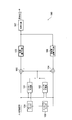
- FIG. 1 is a diagram showing an image processing system 1 according to the present embodiment.
- the image processing system 1 includes an image coding device 100 and an image decoding device 300.
- the image coding device 100 is configured to generate coded data by coding the input image signal.
- the image decoding device 300 is configured to generate an output image signal by decoding the encoded data.
- the coded data may be transmitted from the image coding device 10 to the image decoding device 30 via a transmission line.
- the coded data may be stored in the storage medium and then provided from the image coding device 10 to the image decoding device 30.
- FIG. 2 is a diagram showing an example of a functional block of the image coding apparatus 100 according to the present embodiment.
- the image coding device 100 includes an inter-prediction unit 101, an intra-prediction unit 102, a subtractor 103, an adder 104, a conversion / quantization unit 105, and an inverse conversion / inverse quantization. It has a unit 106, an encoding unit 107, an in-loop filter 108, and a frame buffer 109.
- the inter-prediction unit 101 is configured to generate a prediction signal by inter-prediction (inter-frame prediction).
- the inter-prediction unit 101 identifies and identifies the reference block included in the reference frame by comparing the frame to be encoded (hereinafter referred to as the target frame) with the reference frame stored in the frame buffer 109. It is configured to determine the predicted motion vector for the reference block.
- the reference frame is a frame different from the target frame.
- the reference block is a block that is referred to for the block to be predicted (hereinafter referred to as the target block).
- the inter-prediction unit 101 is configured to generate a prediction signal for each prediction block based on the prediction block and the prediction motion vector. Further, the inter-prediction unit 101 is configured to output the prediction signal to the subtractor 103 and the adder 104.
- the intra prediction unit 102 is configured to generate a prediction signal by intra prediction (in-frame prediction).
- the intra prediction unit 102 is configured to specify a reference block included in the target frame and generate a prediction signal for each prediction block based on the specified reference block.
- the reference block is a block adjacent to the target block.
- the intra prediction unit 102 is configured to output a prediction signal to the subtractor 103 and the adder 104.
- the subtractor 103 is configured to subtract the prediction signal from the input image signal and output the prediction residual signal to the conversion / quantization unit 105.
- the subtractor 103 is configured to generate a prediction residual signal which is a difference between the prediction signal generated by the intra prediction or the inter prediction and the input image signal.
- the adder 104 is configured to add a prediction signal to the prediction residual signal output from the inverse conversion / inverse quantization unit 106 and output the pre-filter decoding signal to the intra prediction unit 102 and the in-loop filter 108.
- the pre-filter decoding signal constitutes a reference block used in the intra prediction unit.
- the conversion / quantization unit 105 is configured to perform conversion processing of the predicted residual signal and acquire a coefficient level value. Further, the conversion / quantization unit 105 may be configured to quantize the coefficient level value.
- the conversion process is a process of converting the predicted residual signal into a frequency component signal.
- a base pattern (transformation matrix) corresponding to the discrete cosine transform (DCT; Discrete Cosine Transform) may be used, and a base pattern (transformation matrix) corresponding to the discrete sine transform (DST) is used. It may be used.
- the inverse conversion / inverse quantization unit 106 is configured to perform an inverse conversion process of the coefficient level value output from the conversion / quantization unit 105.
- the inverse conversion / inverse quantization unit 106 may be configured to perform inverse quantization of the coefficient level value prior to the inverse conversion process.
- the inverse conversion process and the inverse quantization are performed in the reverse procedure of the conversion process and the quantization performed by the conversion / quantization unit 105.
- the coding unit 107 is configured to encode the coefficient level value output from the conversion / quantization unit 105 and output the coded data.
- coding is entropy coding, which assigns codes of different lengths based on the probability of occurrence of coefficient level values.
- the coding unit 107 is configured to encode the control data used in the decoding process in addition to the coefficient level value.
- the control data may include size data such as a coded block size, a predicted block size, and a conversion block size.
- the in-loop filter 108 is configured to filter the pre-filter decoding signal output from the adder 104 and output the post-filter decoding signal to the frame buffer 109.
- the filtering process is a deblocking filtering process that reduces the distortion generated at the boundary portion of a block (predicted block or transformed block).
- the frame buffer 109 is configured to store reference frames used by the inter-prediction unit 101.
- the filtered decoding signal constitutes a reference frame used by the inter-prediction unit 101.
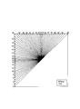
- the intra prediction mode of Versatile Video Coding is selected from a plurality of intra prediction modes.
- VVC For VVC, DC prediction, Planar prediction, and directional prediction, which are also used in High Efficiency Video Coding of Non-Patent Document 4, are still used. Regarding directional prediction, 2 in order to improve prediction performance. The number is doubled.
- the numbers shown in FIG. 3 are uniquely associated with the intra prediction mode number, "0" for planar prediction, "1" for DC prediction, and "2" to "66” for direction prediction. Numbers up to are assigned.
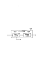
- FIG. 4 is a diagram showing an example of a functional block of the intra prediction unit 102 according to the present embodiment.
- the intra prediction unit 102 includes a prediction mode determination unit 102A and a prediction pixel generation unit 102B.
- the prediction mode determination unit 102A is configured to determine the prediction mode based on the reference image signal of the reference block adjacent to the prediction target pixel.
- the prediction pixel generation unit 102B is configured to generate and output a prediction image signal.
- the prediction mode determined by the prediction mode determination unit 102A is sent to the coding unit 107, included in the coding data as control data (identification flag, hereinafter referred to as “syntax element”), and image decoding. It is configured to be transmitted to the device 300.
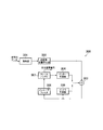
- FIG. 5 is a diagram showing an example of a functional block of the image decoding apparatus 300 according to the present embodiment.
- the image decoding device 300 includes a decoding unit 301, an inverse conversion / inverse quantization unit 302, an adder 303, an inter-prediction unit 304, an intra-prediction unit 305, and an in-loop filter 306. , And a frame buffer 307.
- the decoding unit 301 is configured to decode the coded data generated by the image coding device 100 and decode the coefficient level value.
- the decoding is the entropy decoding in the reverse procedure of the entropy coding performed by the coding unit 107 of the image coding apparatus 100.
- the decoding unit 301 may be configured to acquire control data by decoding the encoded data.
- the control data may include size data such as a coded block size, a predicted block size, and a converted block size.
- the control data may also include an information element indicating an input source used to generate a prediction sample of the second component.
- the second component refers to, for example, a color difference signal other than the luminance signal constituting the image signal.
- the inverse conversion / inverse quantization unit 302 is configured to perform an inverse conversion process of the coefficient level value output from the decoding unit 301.
- the inverse conversion / inverse quantization unit 302 may be configured to perform inverse quantization of the coefficient level value prior to the inverse conversion process.
- the inverse conversion process and the inverse quantization are performed in the reverse procedure of the conversion process and the quantization performed by the conversion / quantization unit 105 of the image coding apparatus 100.
- the adder 303 is configured to add a prediction signal to the prediction residual signal output from the inverse conversion / inverse quantization unit 302 and output the pre-filter decoding signal to the intra prediction unit 305 and the in-loop filter 306. There is.
- the pre-filter decoding signal constitutes a reference block used in the intra prediction unit 395.
- the inter-prediction unit 304 is configured to generate a prediction signal by inter-prediction (inter-frame prediction), similarly to the inter-prediction unit 101 of the image coding device 100.
- the inter-prediction unit 304 identifies the reference block included in the reference frame by comparing the target frame with the reference frame stored in the frame buffer 307, and determines the predicted motion vector for the specified reference block. It is configured to do.
- the inter-prediction unit 304 is configured to generate a prediction signal for each prediction block based on the prediction block and the prediction motion vector.
- the inter-prediction unit 304 is configured to output a prediction signal to the adder 303.
- the intra prediction unit 305 is configured to generate a prediction signal by intra prediction (in-frame prediction), similarly to the intra prediction unit 102 of the image coding device 100.
- the intra prediction unit 305 is configured to specify a reference block included in the target frame and generate a prediction signal for each prediction block based on the specified reference block.
- the intra prediction unit 305 is configured to output a prediction signal to the adder 303.
- the in-loop filter 306 performs filtering processing on the pre-filter decoding signal output from the adder 303, and outputs the post-filter decoding signal to the frame buffer 307. It is configured to do.
- the filtering process is a deblocking filtering process that reduces the distortion generated at the boundary portion of a block (predicted block or transformed block).
- the frame buffer 307 is configured to store reference frames used by the inter-prediction unit 101, similarly to the frame buffer 109 of the image coding device 100.
- the decoded signal after filtering constitutes a reference frame used by the inter-prediction unit 101.
- FIG. 6 is a diagram showing an example of a functional block of the intra prediction unit according to the embodiment.
- the intra prediction unit 305 includes a prediction mode decoding unit 305A and a prediction pixel generation unit 305B.
- the prediction mode decoding unit 305A is configured to decode the prediction mode of the prediction target block based on the control data included in the coding data sent from the image coding device 100 and the reference image signal of the reference block.
- identification flags indicating invalidity and validity of the plurality of intra prediction methods specifically, multiple reference line prediction (MRL), intra subdivision prediction (ISP), direction prediction, and planar prediction are effective, respectively.
- MDL multiple reference line prediction
- ISP intra subdivision prediction
- direction prediction direction prediction
- planar prediction planar prediction
- the prediction mode decoding unit 305A is configured to decode the prediction mode of the prediction target block from the syntax element, the reference image signal of the reference block adjacent to the target block, and the prediction mode.
- the prediction mode decoding unit 305A determines the decoding method of the prediction mode using the above-mentioned syntax element, and when the decoding method satisfies a predetermined condition, the prediction mode is determined by using the MPM list (maximum likelihood mode list). Is configured to decrypt.
- the prediction pixel generation unit 305B is configured to generate and output a prediction image signal of a prediction target block based on the above-mentioned prediction mode and reference image signal.
- the plurality of intra-prediction methods are, for example, MRL and ISP, and the technical contents are shown in Non-Patent Document 1 and Non-Patent Document 2.
- the prediction modes that can be used to generate the predicted image signal are limited to directional prediction, and the use of planar prediction and DC prediction is prohibited. Further, when ISP is valid, the prediction mode that can be used to generate the predicted image signal is limited to planar prediction or directional prediction, and the use of DC prediction is prohibited. The method of determining the prediction mode in the prediction mode decoding unit 305A will be described later.
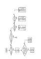
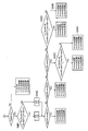
- FIG. 7 is a flowchart showing an example of an operation of decoding various syntax elements sent from the image coding device 100 in the image decoding device 300 according to the present embodiment.
- step S101 the image decoding device 300 decodes the syntax (ref_idx) indicating whether the MRL is invalid or valid.
- the values that "ref_idx” can take are “0”, “1”, and "2".
- step S102 the image decoding device 300 determines whether or not the predetermined condition 1 is satisfied. Here, if the predetermined condition 1 is satisfied, this operation proceeds to step S103, and if the predetermined condition 1 is not satisfied, this operation proceeds to step S107.
- Predetermined condition 1 may include a condition that the decoding result of "ref_idx" is "0".
- the predetermined condition 1 may include a condition that the block to be predicted has a block size that can be predicted by intra-subdivision.
- the block size capable of intra-subdivision prediction means that the width or height of the prediction target block is equal to or less than the maximum size of the conversion block, and the product (area) of the width and height of the prediction target block is It can be set to exceed the minimum area of the conversion block (the number of pixels included in the block). For example, if the maximum size of the conversion block is "64" and the minimum size of the conversion block is "4", 4x8, 8x8, 64x64, 128x32, etc. are the block sizes that can be predicted to be subdivided into intra. Although it is determined, the intra-subdivision prediction is not applied to the block size such as 4x4 or 128x128.
- step S103 the image decoding device 300 decodes "isp_flag", which is a syntax element indicating whether the ISP is invalid or valid.
- the value that "isp_flag” can take is “0" or "1".
- the image decoding device 300 does not apply the ISP to the target block.
- the image decoding apparatus 300 applies the ISP to the target block.
- step S104 the image decoding device 300 determines whether or not the predetermined condition 2 is satisfied. Here, if the predetermined condition 2 is satisfied, this operation proceeds to step S105, and if the predetermined condition 2 is not satisfied, this operation proceeds to step S106.
- Predetermined condition 2 may include a condition that the decoding result of "isp_flag" is "1".
- the predetermined condition 2 may include a condition that the intra subdivision direction is not trivial.
- the intra-subdivision direction is not obvious, it can be set that the target block width and height are equal to or less than the maximum size of the conversion block.
- 4x8, 8x8, 64x64, etc. are intra-fine in either the vertical direction or the horizontal direction.
- 128x32 can be divided in the vertical direction, that is, intra-subblocking can be performed only in the direction in which the intra-subblock becomes 32x32, so that the intra-subdivision direction can be determined to be obvious, and the ISP described later. It is not necessary to decode "ISP_split_flag" which is a syntax element for identifying the division direction of.
- step S105 the image decoding device 300 decodes "isp_split_flag", which is a syntax element that identifies the division direction of the ISP.
- the value that "isp_split_flag” can take is “0” or "1".
- step S106 the image decoding device 300 decodes "angular_flag" which is a syntax element for identifying the invalidity and validity of the direction prediction.
- the value that "angular_flag” can take is “0" or "1".
- the image decoding device 300 does not apply the direction prediction to the target block.
- the image decoding device 300 applies the direction prediction to the target block.
- step S107 the image decoding device 300 determines whether or not the predetermined condition 3 is satisfied. Here, if the predetermined condition 3 is satisfied, this operation proceeds to step S108, and if the predetermined condition 3 is not satisfied, this operation proceeds to step S111.
- the predetermined condition 3 may include a condition that the decoding result of "angular_flag" is "0".
- step S108 the image decoding device 300 determines whether or not the predetermined condition 4 is satisfied. Here, if the predetermined condition 4 is satisfied, this operation proceeds to step S109, and if the predetermined condition 4 is not satisfied, the image decoding apparatus 300 sets the decoding result of the prediction mode to the planar prediction mode. After deciding, this operation is terminated.
- the predetermined condition 4 may include a condition that the decoding result of "isp_flag" is "0".
- step S109 the image decoding device 300 decodes "planar_flag", which is a syntax element that identifies invalidity and validity of the planar prediction.
- the value that "planar_flag” can take is “0” or "1".
- step S110 the image decoding device 300 determines whether or not the predetermined condition 5 is satisfied. Here, if the predetermined condition 5 is satisfied, this operation proceeds to step S111, and if the predetermined condition 5 is not satisfied, this operation proceeds to step S112.
- the predetermined condition 5 may include a condition that "isp_flag” is “0" and “ref_idx” is “0".
- ISP or MRL When either ISP or MRL is valid, it is obvious to decode the prediction mode from the prediction mode of the adjacent reference block, that is, to determine the prediction mode from the prediction mode in the MPM list, which will be described later. It is not necessary to decode the flag "mpm_flag” that identifies whether to decode and determine the prediction mode from the MPM list to be used.
- step S111 the image decoding device 300 decodes "mpm_flag" that identifies whether to select the decoding result of the intra prediction mode from the prediction modes existing in the MPM list.
- the value that "mpm_flag” can take is “0" or "1".
- step S112 the image decoding device 300 determines whether or not the predetermined condition 6 is satisfied. Here, if the predetermined condition 6 is satisfied, this operation proceeds to step S114, and if the predetermined condition 6 is not satisfied, this operation proceeds to step S113.
- the predetermined condition 6 may include a condition that the decoding result of "mpm_flag" is "1".
- step S113 the image decoding device 300 decodes "mpm_idx", which is a syntax element indicating the list number of the prediction mode included in the MPM list, and ends this operation.
- the value that "mpm_idx” can take is determined by the number of MPMs. For example, when there are 6 MPMs, “mpm_idx” is “0", “1", “2", “3", “ It can take values of "4" and "5".
- the priority of the list is devised in the MPM list construction method described later. The effect of improving the coding efficiency can be obtained.
- step S114 the image decoding device 300 decodes "mpm_reminder", which is a syntax element indicating the adopted prediction mode number among all prediction modes excluding the prediction mode included in the MPM list, and ends this operation. ..
- the method for determining the prediction mode using "mpm_reminder" may be determined by comparison with the prediction mode included in the MPM list, as in the method described in Non-Patent Document 1, for example.
- FIG. 8 shows an example of modification 1 regarding the decoding order of the syntax elements for predictive mode decoding.
- the number of syntax elements (code amount) that need to be decoded increases when MRL is valid, while DC prediction or planar prediction is valid when MRL is invalid. If this is the case, or if the ISP is valid and the direction prediction is valid, the effect of reducing the number of syntax elements (code amount) that need to be decoded can be obtained.
- the predetermined condition 1' is different from the predetermined condition 1.
- the predetermined conditions 2'to 4' are the same as the predetermined conditions 2 to 4, respectively.
- the predetermined condition 5' is different from the predetermined condition 5.
- the predetermined condition 6' is a new determination that is not in the above-mentioned decoding order.
- the predetermined condition 7' is the same as the predetermined condition 6.
- FIG. 9 shows a modification 2 regarding the decoding order of the syntax elements for predictive mode decoding.
- Intra-prediction mode decoding method MPM list construction method
- Decoding of the VVC intra-prediction mode is performed by a method of constructing an MPM list using a plurality of MPMs. As shown in FIG. 10, such an MPM list construction method is roughly classified into three types according to the prediction modes of the two reference blocks A and B adjacent to the lower left end and the upper right end of the prediction target block. The three types of cases will be described later.
- the positions of the reference blocks are the lower left end and the upper right end, but they may be the center positions of the left end and the upper end of the prediction target block or the positions adjacent to the upper left end. Moreover, you may use a plurality of reference blocks instead of two reference blocks.
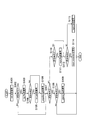
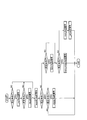
- FIGS. 13 and 14 are diagrams showing an example of a method for constructing an MPM list according to the present embodiment.
- six MPMs are used in constructing the MPM list, but as in Non-Patent Document 1, three MPMs may be used, or another number of MPMs may be used. Good.
- the MPM list construction method shown in FIGS. 13 and 14 is first divided into the following three types according to the prediction modes A / B of the two blocks A / B adjacent to the prediction target block.
- the difference between the MPM list construction method according to the present embodiment and the conventional MPM list construction method is the following two points.
- --First difference DC prediction and planer prediction are uniquely selected by the newly defined syntax elements "angular_flag” and "planar_flag” as described above, and thus are selected from the candidate prediction mode of the MPM list. Points that are always excluded.
- --Second difference Due to the addition of a new syntax element and the devising of the decoding order of the syntax element, the prediction mode candidates that can be included in the MPM list are limited to the direction prediction. Therefore, the MPM list construction method. In, the branch of whether MRL is invalid or valid, that is, the judgment condition by MRL (ref_idx) becomes unnecessary (always excluded from the list).
- step S201 of FIG. 13 when step S201 of FIG. 13 is satisfied, in the conventional MPM construction method, there may be a case where DC prediction or planar prediction is included in the MPM list under the MPM list tree. For example, as such a case, a case where MRL and ISP are invalid is assumed.
- DC prediction and planar prediction are always excluded from the MPM list under step S201. This is because the new syntax element can be used to uniquely identify whether the DC and planar predictions are invalid or valid outside the MPM list, thus adding the DC and planar predictions to the MPM list. This is because it does not need to be included.
- the prediction mode candidates included in the MPM list are limited to the direction prediction. To.
- the branch for determining whether MRL is invalid or valid can always be excluded from the MPM list according to the present embodiment.
- the conventional MPM list construction method since the possibility of selecting DC prediction and planar prediction is left in the MPM list, it is necessary to include a condition for determining invalidity and validity of MRL, and the MPM list is branched. However, as a result, it has increased.
- the determination of the MRL can always be excluded from the MPM list, and as a result, the MPM list tree is simplified.
- step S902 shown in FIG. 11 will be supplementarily described.
- step S902 the prediction modes in the vicinity of A and A are entered, respectively.
- the method of calculating the prediction mode in the vicinity of A is calculated as follows using division in the same manner as the method described in Non-Patent Document 1.
- the prediction mode opposite to A by 180 ° C. is included in the MPM list.
- A 65
- step S209 the image decoding device 300 determines whether or not the difference between "minAB” and "maxAB” is "1".
- the image decoding device 300 confirms whether the prediction modes of A and B are adjacent to each other.
- step S210 when the condition of step S209 is satisfied, that is, because the prediction modes of A and B are adjacent to each other, in step S210, the neighborhood of A and B entering the MPM list [2] [3] [4] [5].
- the value of the prediction mode of is calculated as follows.
- [4] 2+ ((“minAB” +60) / 64) ⁇ It means a prediction mode that is two smaller than “minAB”.
- [5] 2+ (“maxAB” / 64) ⁇ means a prediction mode that is two larger than “maxAB”.
- each proximity mode can be accurately included in the MPM list.
- step S211 the image decoding apparatus 300 determines whether or not the difference between "maxAB” and "minAB” is "2".
- the image decoding device 300 confirms whether or not the prediction modes of A and B are adjacent to each other with one directional prediction mode in between.
- step S211 when the condition of step S211 is satisfied, that is, when the prediction modes of A and B are adjacent to each other with one directional prediction mode in between, in step S212, the MPM list [2] [3] [4] [
- the proximity modes of A and B including the prediction mode between A and B, can be accurately included in the MPM list.
- step S214, step S215, step S216, step S404, and step S406 can be accurately included in the MPM list by using the division of the neighborhood mode of "maxAB” or "minAB” in the same design concept. ..
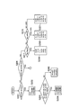
- FIG. 12 shows a determination diagram of the default mode of the MPM list in consideration of the division direction of the ISP.
- ispD1 indicates three default modes.
- three default modes are used, but the number of default modes may be changed according to the number of MPMs included in the MPM list.
- step S301 the image decoding device 300 determines whether or not the decoded “isp_split” is “0”.
- the direction of the ISP and the prediction mode of the adjacent block are far apart, if these three default modes are included in the MPM list, the direction is the same as the division direction that was not selected by the conventional MPM construction method. Since there is a possibility that the prediction mode will be selected, the effect of improving the prediction performance can be obtained as a result.
- step S203 when the condition of step S203 is satisfied, it can be seen from the determination result that the division direction by the ISP is close to A, so that the image decoding apparatus 300 sets the prediction mode in the vicinity of A to the MPM list. You may include it as it is.
- the sub-candidates [3] [4] [5] of the MPM list should include the default mode determined in consideration of the division direction of the ISP.
- step S206 when the condition of step S206 is not satisfied, that is, when A and B are either DC prediction or planar prediction, in the conventional MPM list construction method, DC prediction and DC prediction are performed at the top of the list.
- the planar prediction was included, as described above, when the MPM list construction method according to the present embodiment is adopted, the DC prediction and the planar prediction are always excluded from the MPM list, so that the DC is included in the MPM list.
- Directional predictions other than predictions and planar predictions (A and B) will be selected.
- step S217 the invalidity and validity of the ISP are determined, and when the condition of step S217 is satisfied, that is, when the ISP is invalid, the MPM list includes the vertical mode and the horizontal mode, and then diagonally. Modes will be included in order.
- step S219 When the condition of step S219 is satisfied, that is, when horizontal division is performed, a horizontal mode and a mode close to the horizontal direction (in FIG. 13, a prediction mode "-7" and "+8" away from the horizontal mode are inserted. Is placed at the top of the MPM list and the vertical mode is placed at the bottom of the MPM list, making it easier to select the horizontal mode and making it difficult to select the vertical mode.
- step S219 when the condition of step S219 is not satisfied, that is, when the vertical division is performed, the vertical mode and the mode close to the vertical direction (in FIG. 13, the prediction mode "-7" and “+8" away from the vertical mode are selected. (Insert) is placed at the top of the MPM list, and the horizontal mode is placed at the bottom to make it easier to select the vertical mode while making it difficult to select the horizontal mode.
- the prediction modes relatively far from the lowest prediction mode (in the example of FIG. 12, "-15" and "+15" from the lowest prediction mode.
- the lower prediction mode is set as described above.
- the designer can freely set how far the mode number from the top or bottom is included as the candidate mode other than the top or bottom of the MPM list, but the top of the MPM list is easily selected.
- the code word of "mpm_idx" indicating the predicted mode selected as a result can be reduced, that is, the code amount can be reduced, so that the coding performance can be reduced. Can be expected to improve.
- steps S401, S403, and S405 are added to the method of constructing the MPM list shown in FIGS. 13 and 14 described above.
- step S401 the image decoding apparatus 300 compares the absolute value difference of A and B with respect to "ispD1" when the ISP is valid (the absolute value difference of B with respect to "ispD1" is the absolute value of A with respect to "ispD1". Determine if the difference is small).
- step S401 when the condition of step S401 is not satisfied, that is, when B is the default mode (prediction mode closer to the division direction of the ISP) assigned to "ispD1" than A, the MPM list [0] [1].
- the order of entry is modified from B to A, as shown in step S402.
- step S403 and step S405 the image decoding device 300 compares the absolute value differences of "minAB” and “maxAB” with respect to "ispD1" when the ISP is valid.
- the MPM list tree is simplified by sharing a part of the MPM list tree (steps S902 and S916 in FIG. 11) as compared with the method for constructing the MPM list shown in FIG. There is.
- step S1001 which is the first determination condition, is different from that in FIG.
- step S1001 of FIG. 17 in addition to the condition that A and B are in the same mode and A is larger than DC, A and B are in different modes, and either A or B is in a different mode.
- the condition that the other is DC or planar prediction is added.
- step S1001 A and the MPM list can be displayed. Since it becomes possible to fill in the neighborhood mode of A, the branching of step S902 and step S916 which were branched in FIG. 11 can be shared, and the MPM list tree can be further simplified.
- FIG. 18 is a hybrid MPM list construction method of the above-mentioned modification 1 and modification 2.
- the MPM list construction method according to the third modification is such that the MPM list does not complicate the priority correction of the prediction mode in the MPM list in consideration of the intra-subdivision direction when the ISP described in the modification 1 is valid.
- the invalidity of the ISP and the modification of the prediction mode in consideration of the division direction are applied only to the list construction portion that does not depend on the modes of A and B).
- the syntax that identifies the invalidity and validity of MRL, ISP, direction prediction, and planar prediction By newly defining the tax element, it is possible to simplify the method of constructing the MPM list, which is complicated by the combination of the three types of the conventional MPM list construction method and the determination of validity / invalidity of MRL and ISP.
- the image processing system 1 by devising the decoding order of the above-mentioned syntax elements, it is possible to avoid decoding (signaling) of unnecessary syntax elements.
Landscapes
- Engineering & Computer Science (AREA)
- Multimedia (AREA)
- Signal Processing (AREA)
- Compression Or Coding Systems Of Tv Signals (AREA)
Abstract
本発明に係る画像復号装置300は、画像符号化装置100から送られる符号化データに含まれる制御データ及び参照ブロックの参照画像信号に基づいて、予測対象ブロックの予測モードを復号する予測モード復号部305Aと、予測モードと参照画像信号に基づいて、予測対象ブロックの予測画像信号を生成する予測画素生成部305Bとを備え、制御データは、複数参照ライン予測、イントラ細分割予測、方向性予測、プレーナ予測、最尤モードがそれぞれ有効であるか無効であるかについて示す識別フラグを含み、予測モード復号部305Aは、識別フラグを用いて予測モードの復号方法を決定し、復号方法が所定条件を満たす場合に、最尤モードリストを用いて予測モードを復号する。
Description
本発明は、画像復号装置、画像復号方法及びプログラムに関する。
非特許文献1に、イントラ予測方式に対する予測モードの復号方法が開示されており、計3個の最尤モード(MPM:Most Probable Mode)リストの構築方法を用いた予測モードの復号方法が記されている。
また、非特許文献2に、複数参照ライン予測(MRL:Multi-Reference-Line prediction)という技術が開示されている。
ここで、MRLは、イントラ予測方式の一種で、予測画素生成時に使用する参照画素を、予測対象ブロックに隣接する最近接(0ライン目)の隣接画素を用いるか、或いは、予測対象ブロックに隣接する最近接から1ライン以上離れた隣接画素を用いるかを、適応的に切り替えて予測性能を向上させる技術である。
さらに、非特許文献3に、イントラ細分割予測(ISP:Intra-sub-partitions prediction)いう技術が開示されている。ISPは、イントラ予測方式の一種で、予測対象ブロックをより小さなブロックサイズ(サブブロック)に分割して、サブブロックごとにイントラ予測を行い、予測性能を向上させる技術である。
Versatile Video Coding and Draft 2
Algorithm description for Versatile Video Coding and Test Model 3(VTM3)
CE3:Intra Sub-Partitions Coding Mode(Tests 1.1.1 and 1.1.2)
ITU-T H.265 High Efficiency Video Coding
しかしながら、非特許文献1に開示されているイントラ予測方式の予測モードの復号方法には、非特許文献2に開示されているMRLという概念や非特許文献3に開示されているISPという概念が入っておらず、MRL及びISPの双方を考慮したMPMリスト構築は考慮されていないという問題点があった。
そこで、本発明は、上述の課題に鑑みてなされたものであり、複数のイントラ予測方式を考慮した予測モードの復号方法を実現することができる画像復号装置、画像復号方法及びプログラムを提供することを目的とする。
本発明の第1の特徴は、画像復号装置であって、画像符号化装置から送られる符号化データに含まれる制御データ及び参照ブロックの参照画像信号に基づいて、予測対象ブロックの予測モードを復号する予測モード復号部と、前記予測モードと前記参照画像信号に基づいて、前記予測対象ブロックの予測画像信号を生成する予測画素生成部とを備え、前記制御データは、複数参照ライン予測、イントラ細分割予測、方向性予測、プレーナ予測、最尤モードがそれぞれ有効であるか無効であるかについて示す識別フラグを含み、前記予測モード復号部は、前記識別フラグを用いて前記予測モードの復号方法を決定し、前記復号方法が所定条件を満たす場合に、最尤モードリストを用いて前記予測モードを復号することを要旨とする。
本発明の第2の特徴は、画像復号方法であって、画像符号化装置から送られる符号化データに含まれる制御データ及び参照ブロックの参照画像信号に基づいて、予測対象ブロックの予測モードを復号する工程Aと、前記予測モードと前記参照画像信号に基づいて、前記予測対象ブロックの予測画像信号を生成する工程Bとを有し、前記制御データは、複数参照ライン予測、イントラ細分割予測、方向性予測、プレーナ予測、最尤モードがそれぞれ有効であるか無効であるかについて示す識別フラグを含み、前記工程Aにおいて、前記識別フラグを用いて前記予測モードの復号方法を決定し、前記復号方法が所定条件を満たす場合に、最尤モードリストを用いて前記予測モードを復号することを要旨とする。
本発明の第3の特徴は、コンピュータを、画像復号装置として機能させるプログラムであって、前記画像復号装置は、画像符号化装置から送られる符号化データに含まれる制御データ及び参照ブロックの参照画像信号に基づいて、予測対象ブロックの予測モードを復号する予測モード復号部と、前記予測モードと前記参照画像信号に基づいて、前記予測対象ブロックの予測画像信号を生成する予測画素生成部とを備え、前記制御データは、複数参照ライン予測、イントラ細分割予測、方向性予測、プレーナ予測、最尤モードがそれぞれ有効であるか無効であるかについて示す識別フラグを含み、前記予測モード復号部は、前記識別フラグを用いて前記予測モードの復号方法を決定し、前記復号方法が所定条件を満たす場合に、最尤モードリストを用いて前記予測モードを復号することを特徴とする。
本発明によれば、複数のイントラ予測方式を考慮した予測モードの復号方法を実現することができる画像復号装置、画像復号方法及びプログラムを提供することができる。
以下、図1を参照して、本発明の実施形態に係る画像処理システム1について説明する。図1は、本実施形態に係る画像処理システム1について示す図である。
図1に示すように、本実施形態に係る画像処理システム1は、画像符号化装置100及び画像復号装置300を有する。
画像符号化装置100は、入力画像信号を符号化することによって符号化データを生成するように構成されている。画像復号装置300は、符号化データを復号することによって出力画像信号を生成するように構成されている。
符号化データは、画像符号化装置10から画像復号装置30に対して伝送路を介して送信されてもよい。符号化データは、記憶媒体に格納された上で、画像符号化装置10から画像復号装置30に提供されてもよい。
(画像符号化装置100)
以下、図2を参照して、本実施形態に係る画像符号化装置100について説明する。図2は、本実施形態に係る画像符号化装置100の機能ブロックの一例について示す図である。
以下、図2を参照して、本実施形態に係る画像符号化装置100について説明する。図2は、本実施形態に係る画像符号化装置100の機能ブロックの一例について示す図である。
図2に示すように、画像符号化装置100は、インター予測部101と、イントラ予測部102と、減算器103と、加算器104と、変換・量子化部105と、逆変換・逆量子化部106と、符号化部107と、インループフィルタ108と、フレームバッファ109とを有する。
インター予測部101は、インター予測(フレーム間予測)によって予測信号を生成するように構成されている。
具体的には、インター予測部101は、符号化対象のフレーム(以下、対象フレーム)とフレームバッファ109に格納される参照フレームとの比較によって、参照フレームに含まれる参照ブロックを特定し、特定された参照ブロックに対する予測動きベクトルを決定するように構成されている。
ここで、参照フレームは、対象フレームとは異なるフレームである。参照ブロックは、予測対象のブロック(以下、対象ブロック)について参照されるブロックである。
また、インター予測部101は、予測ブロック及び予測動きベクトルに基づいて予測信号を予測ブロック毎に生成するように構成されている。さらに、インター予測部101は、予測信号を減算器103及び加算器104に出力するように構成されている。
イントラ予測部102は、イントラ予測(フレーム内予測)によって予測信号を生成するように構成されている。
具体的には、イントラ予測部102は、対象フレームに含まれる参照ブロックを特定し、特定された参照ブロックに基づいて予測信号を予測ブロック毎に生成するように構成されている。例えば、参照ブロックは、対象ブロックに隣接するブロックである。
また、イントラ予測部102は、予測信号を減算器103及び加算器104に出力するように構成されている。
減算器103は、入力画像信号から予測信号を減算し、予測残差信号を変換・量子化部105に出力するように構成されている。ここで、減算器103は、イントラ予測又はインター予測によって生成される予測信号と入力画像信号との差分である予測残差信号を生成するように構成されている。
加算器104は、逆変換・逆量子化部106から出力される予測残差信号に予測信号を加算し、フィルタ前復号信号をイントラ予測部102及びインループフィルタ108に出力するように構成されている。ここで、フィルタ前復号信号は、イントラ予測部で用いる参照ブロックを構成する。
変換・量子化部105は、予測残差信号の変換処理を行うとともに、係数レベル値を取得するように構成されている。さらに、変換・量子化部105は、係数レベル値の量子化を行うように構成されていてもよい。
ここで、変換処理は、予測残差信号を周波数成分信号に変換する処理である。変換処理では、離散コサイン変換(DCT;Discrete Cosine Transform)に対応する基底パターン(変換行列)が用いられてもよく、離散サイン変換(DST;Discrete Sine Transform)に対応する基底パターン(変換行列)が用いられてもよい。
逆変換・逆量子化部106は、変換・量子化部105から出力される係数レベル値の逆変換処理を行うように構成されている。ここで、逆変換・逆量子化部106は、逆変換処理に先立って、係数レベル値の逆量子化を行うように構成されていてもよい。逆変換処理及び逆量子化は、変換・量子化部105で行われる変換処理及び量子化とは逆の手順で行われる。
符号化部107は、変換・量子化部105から出力された係数レベル値を符号化し、符号化データを出力するように構成されている。例えば、符号化は、係数レベル値の発生確率に基づいて異なる長さの符号を割り当てるエントロピー符号化である。
また、符号化部107は、係数レベル値に加えて、復号処理で用いる制御データを符号化するように構成されている。ここで、制御データは、符号化ブロックサイズ、予測ブロックサイズ、変換ブロックサイズ等のサイズデータを含んでもよい。
インループフィルタ108は、加算器104から出力されるフィルタ前復号信号に対してフィルタ処理を行うとともに、フィルタ後復号信号をフレームバッファ109に出力するように構成されている。例えば、フィルタ処理は、ブロック(予測ブロック又は変換ブロック)の境界部分で生じる歪みを減少するデブロッキングフィルタ処理である。
フレームバッファ109は、インター予測部101で用いる参照フレームを蓄積するように構成されている。ここで、フィルタ後復号信号は、インター予測部101で用いる参照フレームを構成する。
(イントラ予測モード)
Versatile Video Coding(VVC)のイントラ予測モードは、非特許文献1に記載がある通り、複数のイントラ予測モードから構成されて選択される。
Versatile Video Coding(VVC)のイントラ予測モードは、非特許文献1に記載がある通り、複数のイントラ予測モードから構成されて選択される。
VVCは、非特許文献4のHigh Efficiency Video Codingでも使用されているDC予測やプレーナ(Planar)予測や方向性予測が引き続き使用されており、方向性予測については、予測性能を向上させるために2倍の数となっている。
図3に記載されている数字は、イントラ予測モード番号と一意に対応づいており、プレーナ予測には「0」、DC予測には「1」、方向性予測には「2」~「66」までの番号が割り当てられている。
(画像符号化装置100のイントラ予測部102)
以下、図4を参照して、本実施形態に係る画像符号化装置100のイントラ予測部102について説明する。図4は、本実施形態に係るイントラ予測部102の機能ブロックの一例を示す図である。
以下、図4を参照して、本実施形態に係る画像符号化装置100のイントラ予測部102について説明する。図4は、本実施形態に係るイントラ予測部102の機能ブロックの一例を示す図である。
イントラ予測部102は、予測モード決定部102Aと予測画素生成部102Bとを備えている。
予測モード決定部102Aは、予測対象画素に隣接する参照ブロックの参照画像信号に基づいて、予測モードを決定するように構成されている。予測画素生成部102Bは、予測画像信号を生成して出力するように構成されている。
ここで、予測モード決定部102Aで決定した予測モードは、符号化部107に送られて、制御データ(識別フラグ、以降では「シンタックス要素」と記す)として符号化データに包含され、画像復号装置300に伝送されるように構成されている。
(画像復号装置300)
以下、図5を参照して、本実施形態に係る画像復号装置300について説明する。図5は、本実施形態に係る画像復号装置300の機能ブロックの一例を示す図である。
以下、図5を参照して、本実施形態に係る画像復号装置300について説明する。図5は、本実施形態に係る画像復号装置300の機能ブロックの一例を示す図である。
図5に示すように、画像復号装置300は、復号部301と、逆変換・逆量子化部302と、加算器303と、インター予測部304と、イントラ予測部305と、インループフィルタ306と、フレームバッファ307とを有する。
復号部301は、画像符号化装置100によって生成される符号化データを復号し、係数レベル値を復号するように構成されている。例えば、復号は、画像符号化装置100の符号化部107で行われるエントロピー符号化とは逆の手順のエントロピー復号である。
また、復号部301は、符号化データの復号処理によって制御データを取得するように構成されていてもよい。上述したように、制御データは、符号化ブロックサイズや予測ブロックサイズや変換ブロックサイズ等のサイズデータを含んでもよい。また、制御データは、第2成分の予測サンプルの生成に用いる入力ソースを示す情報要素を含んでもよい。ここで、第2成分とは、例えば、画像信号を構成する輝度信号以外の色差信号を指す。
逆変換・逆量子化部302は、復号部301から出力される係数レベル値の逆変換処理を行うように構成されている。ここで、逆変換・逆量子化部302は、逆変換処理に先立って、係数レベル値の逆量子化を行うように構成されていてもよい。なお、逆変換処理及び逆量子化は、画像符号化装置100の変換・量子化部105で行われる変換処理及び量子化とは逆の手順で行われる。
加算器303は、逆変換・逆量子化部302から出力される予測残差信号に予測信号を加算し、フィルタ前復号信号をイントラ予測部305及びインループフィルタ306に出力するように構成されている。フィルタ前復号信号は、イントラ予測部395で用いる参照ブロックを構成する。
インター予測部304は、画像符号化装置100のインター予測部101と同様に、インター予測(フレーム間予測)によって予測信号を生成するように構成されている。
具体的には、インター予測部304は、対象フレームとフレームバッファ307に格納される参照フレームとの比較によって、参照フレームに含まれる参照ブロックを特定し、特定された参照ブロックに対する予測動きベクトルを決定するように構成されている。
また、インター予測部304は、予測ブロック及び予測動きベクトルに基づいて予測信号を予測ブロック毎に生成するように構成されている。インター予測部304は、予測信号を加算器303に出力するように構成されている。
イントラ予測部305は、画像符号化装置100のイントラ予測部102と同様に、イントラ予測(フレーム内予測)によって予測信号を生成するように構成されている。
具体的には、イントラ予測部305は、対象フレームに含まれる参照ブロックを特定し、特定された参照ブロックに基づいて予測信号を予測ブロック毎に生成するように構成されている。イントラ予測部305は、予測信号を加算器303に出力するように構成されている。
インループフィルタ306は、画像符号化装置100のインループフィルタ108と同様に、加算器303から出力されるフィルタ前復号信号に対してフィルタ処理を行うとともに、フィルタ後復号信号をフレームバッファ307に出力するように構成されている。例えば、フィルタ処理は、ブロック(予測ブロック又は変換ブロック)の境界部分で生じる歪みを減少するデブロッキングフィルタ処理である。
フレームバッファ307は、画像符号化装置100のフレームバッファ109と同様に、インター予測部101で用いる参照フレームを蓄積するように構成されている。フィルタ後復号信号は、インター予測部101で用いる参照フレームを構成する。
(画像復号装置300のイントラ予測部305)
以下、図6を参照して、本実施形態に係る画像復号装置300のイントラ予測部305について説明する。図6は、実施形態に係るイントラ予測部の機能ブロックの一例を示す図である。
以下、図6を参照して、本実施形態に係る画像復号装置300のイントラ予測部305について説明する。図6は、実施形態に係るイントラ予測部の機能ブロックの一例を示す図である。
イントラ予測部305は、予測モード復号部305Aと、予測画素生成部305Bとを備える。
予測モード復号部305Aは、画像符号化装置100から送られる符号化データに含まれる制御データ及び参照ブロックの参照画像信号に基づいて、予測対象ブロックの予測モードを復号するように構成されている。
ここで、制御データは、複数のイントラ予測方式の無効有効を示す識別フラグ、具体的には、複数参照ライン予測(MRL)、イントラ細分割予測(ISP)、方向性予測、プレーナ予測がそれぞれ有効であるか無効であるかについて示す識別フラグ(シンタックス要素)を含む。
予測モード復号部305Aは、かかるシンタックス要素や、対象ブロックに隣接する参照ブロックの参照画像信号及び予測モードから、予測対象ブロックの予測モードを復号するように構成されている。
すなわち、予測モード復号部305Aは、上述のシンタックス要素を用いて予測モードの復号方法を決定し、かかる復号方法が所定条件を満たす場合に、MPMリスト(最尤モードリスト)を用いて予測モードを復号するように構成されている。
予測画素生成部305Bは、上述の予測モード及び参照画像信号に基づいて、予測対象ブロックの予測画像信号を生成して出力するように構成されている。
ここで、複数のイントラ予測方式とは、例えば、MRLやISPであり、技術内容は、非特許文献1や非特許文献2に示されている。
MRLが有効な場合、予測画像信号の生成に利用できる予測モードは、方向性予測に限定されており、プレーナ予測及びDC予測の利用は、禁止されている。また、ISPが有効な場合は、予測画像信号の生成に利用できる予測モードはプレーナ予測又は方向性予測に限定されており、DC予測の利用は、禁止されている。また、予測モード復号部305Aでの予測モードの決定方法については、後述する。
(イントラ予測モードの復号方法:各種シンタックス要素の復号順序)
以下、図7を参照して、本実施形態に係る画像復号装置300(具体的には、イントラ予測部305)の動作について説明する。図7は、本実施形態に係る画像復号装置300において画像符号化装置100から送られる各種シンタックス要素を復号する動作の一例を示すフローチャートである。
以下、図7を参照して、本実施形態に係る画像復号装置300(具体的には、イントラ予測部305)の動作について説明する。図7は、本実施形態に係る画像復号装置300において画像符号化装置100から送られる各種シンタックス要素を復号する動作の一例を示すフローチャートである。
図7に示すように、ステップS101において、画像復号装置300は、MRLが無効であるか有効であるかについて示すシンタックス(ref_idx)を復号する。
ここで、「ref_idx」が取り得る値は、「0」、「1」、「2」である。「ref_idx=0」である場合は、MRLが無効であることを示し、画像復号装置300は、対象ブロックに隣接する参照ブロックのうちブロック境界に位置する最近接(0ライン目)の画素を参照して予測画素を生成する。「ref_idx=1」である場合は、MRLが有効であることを示し、画像復号装置300は、ブロック境界から1ライン離れた画素を参照して予測画素を生成する。「ref_idx=2」である場合は、MRLが有効であることを示し、画像復号装置300は、ブロック境界に位置する画素から3ライン離れた画素を参照して予測画素を生成する。
ステップS102において、画像復号装置300は、所定条件1が満たされているか否かについて判定する。ここで、所定条件1が満たされている場合は、本動作は、ステップS103に進み、所定条件1が満たされていない場合は、本動作は、ステップS107に進む。
所定条件1は、「ref_idx」の復号結果が「0」であることという条件を含んでもよい。
また、所定条件1は、予測対象ブロックがイントラ細分割予測可能なブロックサイズであることという条件を含んでもよい。例えば、イントラ細分割予測が可能なブロックサイズとは、予測対象ブロックの幅或いは高さが、変換ブロックの最大サイズ以下であり、且つ、予測対象ブロックの幅と高さとの積(面積)が、変換ブロックの最小面積(ブロック内に含まれる画素数)を超えることと設定することができる。例えば、変換ブロックの最大サイズが「64」であり且つ変換ブロックの最小サイズが「4」であると値を設定した場合、4x8、8x8、64x64、128x32等がイントラ細分割予測可能なブロックサイズと判定されるが、4x4や128x128といったブロックサイズではイントラ細分割予測が非適用となる。
ステップS103において、画像復号装置300は、ISPが無効であるか有効であるかについて示すシンタックス要素である「isp_flag」を復号する。
ここで、「isp_flag」が取り得る値は、「0」又は「1」である。「isp_flag=0」である場合(すなわち、ISPが無効であることを示す場合)、画像復号装置300は、対象ブロックにISPを適用しない。「isp_flag=1」である場合(すなわち、ISPが有効であることを示す場合)、画像復号装置300は、対象ブロックにISPを適用する。
ステップS104において、画像復号装置300は、所定条件2が満たされているか否かについて判定する。ここで、所定条件2が満たされている場合は、本動作は、ステップS105に進み、所定条件2が満たされていない場合は、本動作は、ステップS106に進む。
所定条件2は、「isp_flag」の復号結果が「1」であることという条件を含んでもよい。
また、所定条件2は、イントラ細分割方向が自明でないことという条件を含んでもよい。ここで、イントラ細分割方向が自明ではないとは、対象ブロック幅及び高さが、変換ブロックの最大サイズ以下であると設定できる。
例えば、変換ブロック最大サイズが「64」であり且つ変換ブロックの最小サイズが「4」であると値を設定した場合、4x8、8x8、64x64等は、垂直方向或いは水平方向のいずれにもイントラ細分割予測が可能と判定されるが、128x32は、垂直方向の分割、すなわち、イントラサブブロックが32x32となる方向にしかイントラ細分割ができないため、イントラ細分割方向が自明と判定でき、後述するISPの分割方向を識別するシンタックス要素である「isp_split_flag」を復号しなくてもよい。
ステップS105において、画像復号装置300は、ISPの分割方向を識別するシンタックス要素である「isp_split_flag」を復号する。
ここで、「isp_split_flag」が取り得る値は、「0」又は「1」である。「isp_split_flag=0」である場合は、水平分割であることを示し、「isp_split_flag=1」である場合は、垂直分割であることを示す。
ステップS106において、画像復号装置300は、方向性予測の無効有効を識別するシンタックス要素である「angular_flag」を復号する。
ここで、「angular_flag」が取り得る値は、「0」又は「1」である。「angular_flag=0」である場合、画像復号装置300は、対象ブロックに方向性予測を適用しない。「angular_flag=1」である場合、画像復号装置300は、対象ブロックに方向性予測を適用する。
なお、「isp_flag」が復号されていない場合、すなわち、所定条件2が満たされていない場合、画像復号装置300は、「isp_flag=0」且つ「angular_flag=1」であるとみなすことができる。
ステップS107において、画像復号装置300は、所定条件3が満たされているか否かについて判定する。ここで、所定条件3が満たされている場合は、本動作は、ステップS108に進み、所定条件3が満たされていない場合は、本動作は、ステップS111に進む。
ここで、所定条件3は、「angular_flag」の復号結果が「0」であることという条件を含んでもよい。
なお、「isp_flag」及び「angular_flag」が復号されていない場合、すなわち、所定条件1が満たされていない場合、画像復号装置300は、「isp_flag=0」且つ「angular_flag=1」であるとみなすことができる。
ステップS108において、画像復号装置300は、所定条件4が満たされているか否かについて判定する。ここで、所定条件4が満たされている場合は、本動作は、ステップS109に進み、所定条件4が満たされていない場合は、画像復号装置300は、予測モードの復号結果をプレーナ予測モードに決定して、本動作を終了する。
ここで、所定条件4は、「isp_flag」の復号結果が「0」であることという条件を含んでもよい。
所定条件4に対する判定を行うことで、「isp_flag=1」である場合は、プレーナ予測に予測モードが一意に決定されるため、後述する「planar_flag」のシンタックス要素の伝送が不要となり、符号量の削減に寄与することができる。
ステップS109において、画像復号装置300は、プレーナ予測の無効有効を識別するシンタックス要素である「planar_flag」を復号する。
ここで、「planar_flag」が取り得る値は、「0」又は「1」である。「planar_flag=0」である場合、画像復号装置300は、対象ブロックにDC予測を適用し、「planar_flag=1」である場合、画像復号装置300は、対象ブロックにプレーナ予測を適用する。
ステップS110において、画像復号装置300は、所定条件5が満たされているか否かについて判定する。ここで、所定条件5が満たされている場合は、本動作は、ステップS111に進み、所定条件5が満たされていない場合は、本動作は、ステップS112に進む。
ここで、所定条件5は、「isp_flag」が「0」であり且つ「ref_idx」が「0」であることという条件を含んでもよい。ISP及びMRLのいずれかが有効である場合は、隣接の参照ブロックの予測モードから予測モードを復号すること、すなわち、MPMリスト内の予測モードから予測モードを決定することが自明であるため、後述するMPMリスト内から予測モードを復号して決定するかどうかを識別するフラグ「mpm_flag」を復号しなくてもよい。
ステップS111において、画像復号装置300は、イントラ予測モードの復号結果をMPMリスト内に存在する予測モードから選択するかどうかを識別する「mpm_flag」を復号する。
ここで、「mpm_flag」が取り得る値は、「0」又は「1」である。「mpm_flag=1」である場合、画像復号装置300は、後述するMPMリスト内に存在する予測モードから選択し、「mpm_flag=0」である場合、画像復号装置300は、MPMリスト内に存在しない予測モードを予測対象ブロックに適用する。
ステップS112において、画像復号装置300は、所定条件6が満たされているか否かについて判定する。ここで、所定条件6が満たされている場合は、本動作は、ステップS114に進み、所定条件6が満たされていない場合は、本動作は、ステップS113に進む。
ここで、所定条件6は、「mpm_flag」の復号結果が「1」であることという条件を含んでもよい。
なお、「mpm_flag」が復号されていない場合、すなわち、所定条件5が満たされていない場合は、画像復号装置300は、「mpm_flag=1」であるとみなすことができる。
ステップS113において、画像復号装置300は、MPMリストに入っている予測モードのリスト番号を示すシンタックス要素である「mpm_idx」を復号して本動作を終了する。
ここで、「mpm_idx」が取り得る値は、MPMの数によって決まり、例えば、MPMが6個である場合、「mpm_idx」は、「0」、「1」、「2」、「3」、「4」、「5」という値を取り得る。「mpm_idx」の値が小さいモードの方が、より少ない符号量で符号化できるように符号語が割り当てられている場合、後述するMPMリストの構築方法において、リストの優先順位を工夫することで、符号化効率が向上する効果が得られる。
ステップS114において、画像復号装置300は、MPMリストに入っている予測モードを省いた全予測モードの中の採用予測モード番号を示すシンタックス要素である「mpm_remainder」を復号して本動作を終了する。
なお、「mpm_remainder」を用いた予測モードの決定方法は、例えば、非特許文献1に記されている方法と同じように、MPMリストに入っている予測モードとの比較により決定されてもよい。
(シンタックス要素の復号順序の変更例1)
以下において、上述した予測モード復号のためのシンタックス要素の復号順序についての変更例1を説明する。図8は、予測モード復号のためのシンタックス要素の復号順序についての変更例1を示す。
以下において、上述した予測モード復号のためのシンタックス要素の復号順序についての変更例1を説明する。図8は、予測モード復号のためのシンタックス要素の復号順序についての変更例1を示す。
上述の復号順序との差異は、「ref_idx」の判定位置が復号順序の最初ではなく、「isp_flag」及び「angular_flag」の判定後に位置する点である。
このように復号順序を変更することで、MRLが有効な場合に復号が必要なシンタックス要素数(符号量)は増加してしまう一方、MRLが無効な場合で且つDC予測又はプレーナ予測が有効な場合、或いは、ISPが有効な場合で且つ方向性予測が有効な場合、復号が必要なシンタックス要素数(符号量)は減少する効果が得られる。
以下、図8を用いて、復号順序の変更例の詳細について説明する。
まず、所定条件1’は、所定条件1と異なる。所定条件1’には、所定条件1に含まれている「ref_idx=0」の判定が含まれない。これは、上述した通り、「ref_idx」による判定が復号順序の後段に位置するためである。
次に、所定条件2’~4’は、所定条件2~4とそれぞれ同じである。
さらに、所定条件5’は、所定条件5と異なる。所定条件5’には、所定条件5に含まれている「ref_idx=0」の判定が含まれない。これは、上述した通り、「ref_idx」による判定が復号順序の本所定条件の直後に位置するためである。
さらに、所定条件6’は、上述の復号順所にはない新規の判定である。所定条件6’には、「ref_idx=0」の判定が含まれる。これは、上述した通り、MRLが有効の場合は、MPMリスト内に含まれる予測モードから予測モードを復号することが自明であるため、「mpm_flag」の復号を省略するためである。
さらに、所定条件7’は、所定条件6と同じである。
(シンタックス要素の復号順序の変更例2)
以下において、上述した予測モード復号のためのシンタックス要素の復号順序についての変更例2を説明する。図9は、予測モード復号のためのシンタックス要素の復号順序についての変更例2を示す。
以下において、上述した予測モード復号のためのシンタックス要素の復号順序についての変更例2を説明する。図9は、予測モード復号のためのシンタックス要素の復号順序についての変更例2を示す。
上述の変更例1との違いは、「ref_idx」の復号位置をツリーの最終段に配置変更した点である。これにより、MRLが有効な場合に復号が必要なシンタックス要素数(符号量)は増加してしまう一方、MRLが無効の場合、特に、MRLが無効な場合で且つ「mpm_flag=0」である場合に必要なシンタックス(符号量)は、上述の変更例1と比較してさらに減少する効果が得られる。
(イントラ予測モードの復号方法:MPMリストの構築方法)
VVCのイントラ予測モードの復号は、複数のMPMを用いたMPMリストの構築方法によって実施される。かかるMPMリストの構築方法は、図10に示すように、予測対象ブロックの左下端と右上端に隣接する2つの参照ブロックA及びBが有する予測モードによって、大きく3種類に場合分けされる。かかる3種類の場合分けについては後述する。
VVCのイントラ予測モードの復号は、複数のMPMを用いたMPMリストの構築方法によって実施される。かかるMPMリストの構築方法は、図10に示すように、予測対象ブロックの左下端と右上端に隣接する2つの参照ブロックA及びBが有する予測モードによって、大きく3種類に場合分けされる。かかる3種類の場合分けについては後述する。
なお、図10では、参照ブロックの位置を左下端及び右上端としているが、予測対象ブロックの左端及び上端の中央位置や、左上端に隣接する位置にしてもよい。また、2つの参照ブロックではなく、複数の参照ブロックを用いてもよい。
以降で説明するMPMリストの構築方法では、非特許文献1とは異なり、MPMリストの中からDC予測及びプレーナ予測が常に除外されている。その理由は、上述した通り、DC予測及びプレーナ予測は、シンタックス要素によって一意に無効であるか有効であるかが識別されるためである。これにより、DC予測及びプレーナ予測をMPMリストの構築方法から除外して、DC予測及びプレーナ予測以外の予測モードを優先的にMPMリストに入れられるため、非特許文献1に記されているようなMPMリストの構築方法と比較して、MPMリストの構築方法を簡素化できる効果が得られる。
以降で、上述のシンタックス要素の復号結果に基づいたMPMリスト構築方法の詳細について説明する。
(イントラ予測モードの復号方法:DC予測及びプレーな予測を除外したMPMリストの構築方法)
以下、図13及び図14を参照して、本実施形態に係るMPMリストの構築方法について説明する。図13及び図14は、本実施形態に係るMPMリストの構築方法の一例について示す図である。図13及び図14の例では、MPMリストの構築にあたって、6個のMPMを用いているが、非特許文献1のように、3個のMPMを使う等、他の個数のMPMを用いてもよい。
以下、図13及び図14を参照して、本実施形態に係るMPMリストの構築方法について説明する。図13及び図14は、本実施形態に係るMPMリストの構築方法の一例について示す図である。図13及び図14の例では、MPMリストの構築にあたって、6個のMPMを用いているが、非特許文献1のように、3個のMPMを使う等、他の個数のMPMを用いてもよい。
図13及び図14に示すMPMリストの構築方法は、予測対象ブロックに隣接する2つのブロックA/Bの予測モードA/Bに応じて、まず初めに、以下の3種類に場合分けを行うが、かかる方法は、非特許文献1及び4記されているMPMリストの構築方法(以下、従来MPMリスト構築方法と記す)の3種類の場合分け(下記参照)と同じである。
1)A及びBが同じ予測モードで、且つ、Aが1よりも大きい場合(A=Bが、DC予測又はプレーナ予測ではない場合)、
2)A及びBが違う予測モードで、且つ、A又はBが1よりも大きい場合(A及びBのいずれかがDC予測又はプレーナ予測である場合)、
3)A及びB違う予測モードで、且つ、A及びBが1よりも大きい場合(A及びBのいずれもDC予測又はプレーナ予測ではない場合)、
ここで、(1)についての判定は、図13のステップS201に対応し、(2)及び(3)についての判定は、図13のステップS206及び図14のS207に対応する。
1)A及びBが同じ予測モードで、且つ、Aが1よりも大きい場合(A=Bが、DC予測又はプレーナ予測ではない場合)、
2)A及びBが違う予測モードで、且つ、A又はBが1よりも大きい場合(A及びBのいずれかがDC予測又はプレーナ予測である場合)、
3)A及びB違う予測モードで、且つ、A及びBが1よりも大きい場合(A及びBのいずれもDC予測又はプレーナ予測ではない場合)、
ここで、(1)についての判定は、図13のステップS201に対応し、(2)及び(3)についての判定は、図13のステップS206及び図14のS207に対応する。
本実施形態に係るMPMリストの構築方法と従来MPMリスト構築方法との相違点は、以下の2点である。
- 第1相違点: DC予測及びプレーナ予測は、上述のように、新たに定義されたシンタックス要素である「angular_flag」及び「planar_flag」で一意に選択されるため、MPMリストの候補予測モードから常に除外される点。
- 第2相違点: 新規のシンタックス要素の追加及び当該シンタックス要素の復号順序の工夫により、MPMリスト内に入る予測モードの候補は、方向性予測に限定されるため、MPMリストの構築方法において、MRLが無効であるか有効であるかの分岐、すなわち、MRL(ref_idx)による判定条件が不要となる(常にリストから除外される)。
- 第1相違点: DC予測及びプレーナ予測は、上述のように、新たに定義されたシンタックス要素である「angular_flag」及び「planar_flag」で一意に選択されるため、MPMリストの候補予測モードから常に除外される点。
- 第2相違点: 新規のシンタックス要素の追加及び当該シンタックス要素の復号順序の工夫により、MPMリスト内に入る予測モードの候補は、方向性予測に限定されるため、MPMリストの構築方法において、MRLが無効であるか有効であるかの分岐、すなわち、MRL(ref_idx)による判定条件が不要となる(常にリストから除外される)。
上述の第1~2相違点の作用として、MPMリストの構築方法が従来MPM構築方法と比較して簡素化されるという効果を得ることができる。以下で、第1~2相違点のそれぞれの詳細について説明する。
(第1の相違点)
以下、上述の第1相違点について説明する。
以下、上述の第1相違点について説明する。
例えば、図13のステップS201が満たされる場合、従来MPM構築方法では、かかるMPMリストツリーの配下で、MPMリスト内にDC予測或いはプレーナ予測が含まれるケースが存在し得た。例えば、かかるケースとして、MRL及びISPが無効であるケースが想定される。
A及びBが共に、DC予測及びプレーナ予測ではない場合であっても、DC予測及びプレーナ予測は、方向性予測と比較して、一般に選択されやすい予測モードであるため、従来MPM構築方法では、MPMリスト内に選択される可能性が残していた。
一方で、本実施形態に係る技術を適用した場合、ステップS201配下で、MPMリスト内からDC予測及びプレーナ予測が常に除外される。これは、新規のシンタックス要素を用いてDC予測及びプレーナ予測が無効であるか有効であるかどうかを、MPMリストの外で一意に識別可能なことから、MPMリストにDC予測及びプレーナ予測を含める必要がないためである。
MPMリスト内からDC予測及びプレーナ予測を常に除外できることは、MPMリスト内の予測モードの候補を方向性予測で全て埋められることに繋がるため、結果的に、DC予測及びプレーナ予測の選択可能性を残していたリストのツリー部を削除でき、MPMリストツリーが簡素化される。
(第2相違点)
以下、第2相違点について説明する。
以下、第2相違点について説明する。
上述のように、図8又は図9で示した新規のシンタックス要素の追加及び当該シンタックス要素の復号順序の工夫により、MPMリスト内に含まれる予測モードの候補は、方向性予測に限定される。
そのため、本実施形態に係るMPMリストからはMRLが無効であるか有効であるかを判定する分岐を常に除外することができる。従来のMPMリスト構築方法では、上述の通り、MPMリスト内にDC予測及びプレーナ予測の選択の可能性を残していたために、MRLの無効有効を判定する条件を入れる必要があり、MPMリストの分岐が、結果的に増大してしまっていた。
本実施形態に係るMPMリストの構築方法は、MPMリストの外でMRLの無効有効を判定するため、MPMリストからMRLの判定を常に除外することができ、結果的にMPMリストツリーが簡素化される。
(MPMリスト内の方向性予測の近傍モードの算出方法)
ここで、図11に示すステップS902について補足して説明する。
ここで、図11に示すステップS902について補足して説明する。
ステップS902のMPMリスト[0][1][2][3][4][5]には、それぞれA、Aの近傍の予測モードが入るようになっている。ここでAの近傍の予測モードの算出方法は、非特許文献1に記載がある方法と同じく、除算を用いて以下のように算出される。
[0]=A
[1]=2+((「A」+61)/64)
[2]=2+((「A」-1)/64)
[3]=2+((「A」+60)/64)
[4]=2+((「A」/64)
[5]=2+((「A」+58)/64)
このように除算を用いた算出方法により、いずれの方向性予測モードの番号でも、そのモードの近傍のモードがリストに入るようになっている。
[0]=A
[1]=2+((「A」+61)/64)
[2]=2+((「A」-1)/64)
[3]=2+((「A」+60)/64)
[4]=2+((「A」/64)
[5]=2+((「A」+58)/64)
このように除算を用いた算出方法により、いずれの方向性予測モードの番号でも、そのモードの近傍のモードがリストに入るようになっている。
例えば予測モードが10の場合、MPMリストは以下のように算出方法される。
[0]=10
[1]=9
[2]=11
[3]=8
[4]=12
[5]=7
[0]=10
[1]=9
[2]=11
[3]=8
[4]=12
[5]=7
また、Aが予測モードの3あるいは66付近の値を取る場合は、Aと180℃反対の予測モードがMPMリスト内に含まれることとなる。例えば、Aが65の場合は、以下のようにMPMリスト内の予測モードが算出される。
[0]=65
[1]=64
[2]=2
[3]=63
[4]=3
[5]=62
[0]=65
[1]=64
[2]=2
[3]=63
[4]=3
[5]=62
次に、図14に示すステップS209、ステップS210及びステップS211の処理について補足して説明する。
第1に、ステップS209において、画像復号装置300は、「minAB」と「maxAB」との差が「1」であるか否かについて判定する。
ここで、「minAB」及び「maxAB」について、AとBのモード番号を比較して、小さい方の予測モードを「minAB」とし、大きい方の予測モードを「maxAB」とするものである。
この結果、画像復号装置300は、A及びBの予測モードが隣接するかどうかについて確認する。
ここで、ステップS209の条件が満たされる場合、すなわち、A及びBの予測モードが隣接するため、ステップS210において、MPMリスト[2][3][4][5]に入るA及びBの近傍の予測モードの値が、以下のように算出される。なお、近傍の予測モードの算出方法は、前述で示したものと同じ設計思想である。
[2]=2+((「minAB」+61)/64) ⇒「minAB」に対して1つ小さい予測モードを意味する。
[3]=2+((「maxAB」-1)/64)⇒「maxAB」に対して1つ大きい予測モードを意味する。
[4]=2+((「minAB」+60)/64)⇒「minAB」に対して2つ小さい予測モードを意味する。
[5]=2+(「maxAB」/64)⇒「maxAB」に対して2つ大きい予測モードを意味する。
[2]=2+((「minAB」+61)/64) ⇒「minAB」に対して1つ小さい予測モードを意味する。
[3]=2+((「maxAB」-1)/64)⇒「maxAB」に対して1つ大きい予測モードを意味する。
[4]=2+((「minAB」+60)/64)⇒「minAB」に対して2つ小さい予測モードを意味する。
[5]=2+(「maxAB」/64)⇒「maxAB」に対して2つ大きい予測モードを意味する。
この結果、A及びBが隣接する予測モードであっても、それぞれの近接モードを正確にMPMリスト内に含めることができる。
第2に、ステップS211において、画像復号装置300は、「maxAB」と「minAB」との差が「2」であるか否かについて判定する。
この結果、画像復号装置300は、A及びBの予測モードが間に1つの方向性予測モードを挟んで隣接するかどうかについて確認する。
ここで、ステップS211の条件が満たされる場合、すなわち、A及びBの予測モードが1つの方向性予測モードを挟んで隣接する場合、ステップS212において、MPMリスト[2][3][4][5]に入るA及びBの近傍モードの値が、以下のようになる。
[2]=2+((「minAB」-1)/64)⇒ 「minAB」-1に対して1つ小さい予測モードを意味する。
[3]=2+((「minAB」+61)/64)⇒「minAB」-1に対して1つ大きい予測モードを意味する。
[4]=2+((「maxAB」-1)/64)⇒「maxAB」に対して1つ大きい予測モードを意味する。
[5]=2+((「minAB」+60)/64)⇒ 「minAB」に対して2つ小さい予測モードを意味する。
[2]=2+((「minAB」-1)/64)⇒ 「minAB」-1に対して1つ小さい予測モードを意味する。
[3]=2+((「minAB」+61)/64)⇒「minAB」-1に対して1つ大きい予測モードを意味する。
[4]=2+((「maxAB」-1)/64)⇒「maxAB」に対して1つ大きい予測モードを意味する。
[5]=2+((「minAB」+60)/64)⇒ 「minAB」に対して2つ小さい予測モードを意味する。
この結果、AとBとの間の予測モードを含めたA及びBの近接モードを正確にMPMリスト内に含めることができる。
その他、ステップS214、ステップS215、ステップS216、ステップS404及びステップS406についても、同じ設計思想で、「maxAB」或いは「minAB」の近傍モードの除算を用いることで、正確にMPMリストに含めることができる。
(変更例1)
以下、第3相違点のうち、ISPが有効である場合のMPMリストの構築方法におけるMPMリスト内の水平モード及び垂直モードの優先選択について説明する。
以下、第3相違点のうち、ISPが有効である場合のMPMリストの構築方法におけるMPMリスト内の水平モード及び垂直モードの優先選択について説明する。
ISPが有効な場合、ISPの分割方向に近い予測モードが選択されることが望ましい。すなわち、水平分割が行われる場合は、水平方向の予測モードが優先的に選択されることが望ましく、垂直分割が行われる場合は、垂直方向の予測モードが優先的に選択されることが望ましい。かかる要求を満たすために、ISP有効時にMPMリストに入る3個の候補パラメータ(デフォルトモード)を新たに定義した。
以下、図12を参照して、ISPの分割方向を考慮したMPMリストのデフォルトモードについて説明する。図12は、ISPの分割方向を考慮したMPMリストのデフォルトモードの判定図を示している。
ここで、「ispD1」、「ispD2」及び「ispD3」は、3個のデフォルトモードを示す。なお、図12の例では、3個のデフォルトモードを用いているが、MPMリストに入るMPMの数に応じて、デフォルトモードの数を変更してもよい。
図12に示すように、ステップS301において、画像復号装置300は、復号した「isp_split」が「0」であるか否かについて判定する。
ここで、「isp_split=0」である場合、上述のように、水平分割が行われるため、水平方向に近い予測モードが優先的に選択されることが望ましい。
したがって、「isp_split=0」である場合、ステップS302において、「ispD1」、「ispD2」及び「ispD3」には、水平予測モード(モード番号:18)、続いて水平方向に近い予測モード(モード番号:5、11)が代入される。
一方で、「isp_split=1」である場合、上述のように、垂直分割が行われるため、垂直方向に近い予測モードが優先的に選択されることが望ましい。
したがって、「isp_split=1」である場合、ステップS303において、「ispD1」、「ispD2」及び「ispD3」には、垂直予測モード(モード番号:50)、続いて垂直方向に近い予測モード(モード番号:63、57)が代入される。
ISPの分割方向及び隣接ブロックの予測モードが仮に大きく離れてしまう場合、かかる3個のデフォルトモードをMPMリスト内に含めるようにすれば、従来MPM構築方法では選択されなかった分割方向と同じ方向の予測モードが選択される可能性が残るため、結果的に予測性能向上という効果が得られる。
以下に、上述のケースの適用例について示す。
例えば、図13において、ステップS203の条件が満たされる場合は、かかる判定結果から、ISPによる分割方向がAに近いことが分かるため、画像復号装置300は、Aの近傍の予測モードをMPMリストにそのまま含めてもよい。
一方、図13において、ステップS203の条件が満たされない場合には、MPMリストの上位候補[0][1][2]には、分割方向とは異なる予測モードA及びその近傍の予測モードで埋められてしまう。したがって、分割方向を考慮した予測モードの選択可能性を残すために、MPMリストの下位候補[3][4][5]には、ISPの分割方向を考慮して決定したデフォルトモードを含めるようにすることで、仮に、ISPの分割方向に対して隣接ブロックの予測モードが極端に離れる場合であっても、MPMリスト内にISPの分割方向に近い予測モードが入れられる。
また、例えば、図13において、ステップS206の条件が満たされない場合、すなわち、A及びBがDC予測或いはプレーナ予測のいずれかである場合、従来のMPMリスト構築方法では、リストの上位にDC予測及びプレーナ予測が入っていたが、上述のように、本実施形態に係るMPMリスト構築方法を採る場合、MPMリストからはDC予測及びプレーナ予測が常に除外されているため、MPMリスト内には、DC予測及びプレーナ予測(A及びB)以外の方向性予測が選択されることとなる。
そのため、ステップS217では、ISPの無効有効が判定され、ステップS217の条件が満たされる場合、すなわち、ISPが無効である場合は、MPMリスト内には、垂直モード、水平モードが入った後、斜めモードが順に含まれるようになる。
一方で、図13のステップS217において、ISPが有効であると判定された場合には、上述のように、ISPの分割方向を考慮して予測モードを選択することが望ましいため、ステップS219で「isp_split=0」であるか否かについて判定される。
ステップS219の条件が満たされる場合、すなわち、水平分割が行われる場合は、水平モード及び水平方向に近いモード(図13では、水平モードから「-7」、「+8」離れた予測モードを入れている)をMPMリストの上位に配置し、垂直モードをMPMリストの最下位に配置することで、水平モードが選択されやすくしつつ、垂直モードが選択されにくくしている。
一方、ステップS219の条件が満たされない場合、すなわち、垂直分割が行われる場合は、垂直モード及び垂直方向に近いモード(図13では、垂直モードから「-7」、「+8」離れた予測モードを入れている)をMPMリスト内の上位に配置し、水平モードを最下位に配置して、垂直モードが選択されやすくしつつ、水平モードが選択されにくくしている。
また、MPMリスト内の中間の位置[3][4]には、最下位の予測モードから比較的遠い予測モード(図12の例では、最下位の予測モードから「-15」、「+15」離れた予測モード)をそれぞれ含めるようにすることで、MPMリストを用いて決定する予測モードが、MPMリスト内の上位の予測モードから外れる場合であっても、下位の予測モードを上述のようにある程度幅を持たせた候補とすることで、本来選択されるべき予測モードから外れにくくすることができる。
MPMリストの最上位又は最下位以外の候補モードとして、それぞれ最上位又は最下位からどれだけ離れたモード番号を含めるかは、設計者が自由に設定可能だが、MPMリストの上位が選択されやすく、MPMリストの下位が選択されにくいモード番号を入れることで、結果的に選択される予測モードを表す「mpm_idx」の符号語を小さくする、すなわち、符号量を小さくすることができるため、符号化性能の向上が期待できるようになる。
以下、図15及び図16を参照して、変更例1のうち、ISPを考慮したMPMリスト内の候補予測モードの優先順位の変更について説明する。
図15及び図16には、上述の図13及び図14に示すMPMリストの構築方法に対して、ステップS401、ステップS403及びステップS405の判定が追加されている。
ステップS401において、画像復号装置300は、ISPが有効である場合、「ispD1」に対するA及びBの絶対値差を比較する(「ispD1」に対するBの絶対値差が「ispD1」に対するAの絶対値差が小さいか否かについて判定する)。
かかる比較を新たに入れることで、ISPの分割方向に対して、A又はBBのどちらの予測モードが近いかを比較することでき、近い方のMPMリスト内の優先度を修正することができる。
例えば、ステップS401の条件が満たされない場合、すなわち、BがAよりも「ispD1」に代入されているデフォルトモード(ISPの分割方向に近い予測モード)である場合、MPMリスト[0][1]に入る順序が、ステップS402に示すように、BからAという順序に修正される。
同様に、ステップS403及びステップS405においても、画像復号装置300は、ISPが有効である場合、「ispD1」に対する「minAB」及び「maxAB」の絶対値差を比較する。
「ispD1」に対する「minAB」及び「maxAB」の絶対値差を比較することで、ISPの分割方向に近い予測モードのMPMリスト内における優先度を、ステップS404及びステップS406に示すように修正することができる。
(変更例2:MPMリストの一部共通化による簡素化)
以下、図17を参照して、MPMリストの構築方法の簡素化例について示す。図17は、図11に示すMPMリストの構築方法と比較して、MPMリストツリーの一部(図11のステップS902及びステップS916)が共通化されることにより、MPMリストツリーが簡素化されている。
以下、図17を参照して、MPMリストの構築方法の簡素化例について示す。図17は、図11に示すMPMリストの構築方法と比較して、MPMリストツリーの一部(図11のステップS902及びステップS916)が共通化されることにより、MPMリストツリーが簡素化されている。
以下に、MPMリストの共通化したポイントを説明する。
まず、図17では、最初の判定条件であるステップS1001が、図11と異なっている。図17のステップS1001には、A及びBが同じモードであり、且つ、AがDCよりも大きいという条件に加えて、A及びBが異なるモードであり、且つ、A及びBのいずれか一方が方向性予測で、もう一方がDC又はプレーナ予測であるという条件が追加されている。
さらに、ステップS1001の直後で、Aを「maxAB」であると再定義することで、仮に、上述のステップS1001で、A及びBが異なるモードである場合であっても、MPMリスト内をA及びAの近傍モードで埋めることができるようになるため、図11で分岐していたステップS902及びステップS916の分岐を共通化することができ、MPMリストツリーを更に簡素化することができる。
(変更例3:変更例1と変更例2のハイブリッド型)
図18は、上述の変更例1及び変更例2のハイブリッド型のMPMリスト構築方法である。本変更例3に係るMPMリスト構築方法は、変更例1で説明したISPが有効である場合にイントラ細分割方向を考慮したMPMリスト内の予測モードの優先度修正をMPMリストが煩雑化しない程度(例えば、図18のステップS1201とステップS1202ように、AとBのモードに依存しないリスト構築部分にのみ、ISPの無効有効及び分割方向を考慮した予測モードの修正を適用)に抑えつつ、さらに、変更例2で説明したMPMリストの一部を共通化することで、符号化性能向上とMPMリストの簡素化双方の効果が期待できる手法である。
図18は、上述の変更例1及び変更例2のハイブリッド型のMPMリスト構築方法である。本変更例3に係るMPMリスト構築方法は、変更例1で説明したISPが有効である場合にイントラ細分割方向を考慮したMPMリスト内の予測モードの優先度修正をMPMリストが煩雑化しない程度(例えば、図18のステップS1201とステップS1202ように、AとBのモードに依存しないリスト構築部分にのみ、ISPの無効有効及び分割方向を考慮した予測モードの修正を適用)に抑えつつ、さらに、変更例2で説明したMPMリストの一部を共通化することで、符号化性能向上とMPMリストの簡素化双方の効果が期待できる手法である。
本実施形態に係る画像処理システム1によれば、複数のイントラ予測方式(MRLやISP)を考慮した予測モードの復号方法において、MRLやISPや方向性予測やプレーナ予測の無効有効を識別するシンタックス要素を新たに定義することで、従来MPMリスト構築方法の3種類と、MRL及びISPの有効・無効の判定との組み合わせで複雑化するMPMリストの構築方法を簡素化することができる。
さらに、本実施形態に係る画像処理システム1によれば、上述のシンタックス要素の復号順序を工夫することで、不要なシンタックス要素の復号(シグナリング)を回避できる。
1…画像処理システム
100…画像符号化装置
101、304…インター予測部
102、305…イントラ予測部
102A…予測モード決定部
102B、305B…予測画素生成部
103…減算器
104、303…加算器
105…変換・量子化部
106、302…逆変換・逆量子化部
107…符号化部
108、306…インループフィルタ
109、307…フレームバッファ
300…画像復号装置
301…復号部
305A…予測モード復号部
100…画像符号化装置
101、304…インター予測部
102、305…イントラ予測部
102A…予測モード決定部
102B、305B…予測画素生成部
103…減算器
104、303…加算器
105…変換・量子化部
106、302…逆変換・逆量子化部
107…符号化部
108、306…インループフィルタ
109、307…フレームバッファ
300…画像復号装置
301…復号部
305A…予測モード復号部
Claims (15)
- 画像符号化装置から送られる符号化データに含まれる制御データ及び参照ブロックの参照画像信号に基づいて、予測対象ブロックの予測モードを復号する予測モード復号部と、
前記予測モードと前記参照画像信号に基づいて、前記予測対象ブロックの予測画像信号を生成する予測画素生成部とを備え、
前記制御データは、複数参照ライン予測、イントラ細分割予測、方向性予測、プレーナ予測、最尤モードがそれぞれ有効であるか無効であるかについて示す識別フラグを含み、
前記予測モード復号部は、前記識別フラグを用いて前記予測モードの復号方法を決定し、前記復号方法が所定条件を満たす場合に、最尤モードリストを用いて前記予測モードを復号することを特徴とする画像復号装置。 - 前記予測モード復号部は、
前記予測対象ブロックが、イントラ細分割予測可能なブロックサイズである場合、前記イントラ細分割予測の識別フラグを復号し、
前記予測対象ブロックが、イントラ細分割予測可能なブロックサイズではない場合、前記イントラ細分割予測の識別フラグを復号せずに、前記イントラ細分割予測が無効であるとみなし、且つ、前記方向性予測が有効であるとみなすように、
前記予測モードの復号方法を決定することを特徴とする請求項1に記載の画像復号装置。 - 前記予測モード復号部は、
前記予測対象ブロックが、イントラ細分割予測可能なブロックサイズであり、且つ、前記複数参照ライン予測の識別フラグが、前記複数参照ライン予測が無効であることを示す場合、前記イントラ細分割予測の識別フラグを復号し、
前記予測対象ブロックがイントラ細分割予測可能なブロックサイズではないか、又は、前記複数参照ライン予測の識別フラグが、前記複数参照ライン予測が有効であることを示す場合、前記イントラ細分割予測の識別フラグを復号せずに、前記イントラ細分割予測が無効であるとみなし、且つ、前記方向性予測が有効であるとみなすように、
前記予測モードの復号方法を決定することを特徴とする請求項1に記載の画像復号装置。 - 前記予測モード復号部は、
前記イントラ細分割予測の識別フラグが、前記イントラ細分割予測が有効であることを示し、且つ、前記イントラ細分割方向が自明ではない場合、前記イントラ細分割予測の分割方向を識別する識別フラグを復号し、
前記イントラ細分割予測の識別フラグが、前記イントラ細分割予測が無効であることを示すか、又は、前記イントラ細分割予測が有効であっても前記イントラ細分割方向が自明である場合、前記イントラ細分割予測の分割方向を識別する識別フラグを復号せず、前記方向性予測の識別フラグを復号するように、
前記予測モードの復号方法を決定することを特徴とする請求項2又は3に記載の画像復号装置。 - 前記予測モード復号部は、
前記方向性予測の識別フラグが、前記方向性予測が無効であることを示す場合において、
前記イントラ細分割予測の識別フラグが、前記イントラ細分割予測が無効であることを示す場合は、前記プレーナ予測モードの識別フラグを復号するように、前記予測モードの復号方法を決定し、
前記イントラ細分割予測の識別フラグが、前記イントラ細分割予測が有効であることを示す場合は、前記プレーナ予測モードの識別フラグを復号せず、プレーナ予測モードに決定するように、
前記予測モードの復号方法を決定することを特徴とする請求項1~4のいずれか一項に記載の画像復号装置。 - 前記予測モード復号部は、
前記方向性予測の識別フラグが、前記方向性予測が有効であることを示す場合において、
前記イントラ細分割予測の識別フラグが、前記イントラ細分割予測が無効であることを示し、且つ、前記複数参照ライン予測の識別フラグが、前記複数参照ライン予測が無効であることを示す場合、前記最尤モードの識別フラグを復号し、
前記イントラ細分割予測の識別フラグが、前記イントラ細分割予測が有効であることを示す場合、前記最尤モードの識別フラグを復号しないように、
前記予測モードの復号方法を決定することを特徴とする請求項1、3、4又は5に記載の画像復号装置。 - 前記予測モード復号部は、
前記方向性予測の識別フラグが、前記方向性予測が有効であることを示す場合において、
前記イントラ細分割予測の識別フラグが、前記イントラ細分割予測が無効であることを示す場合、前記複数参照ラインを識別するフラグを復号し、
前記複数参照ライン予測の識別フラグが、前記複数参照ライン予測が有効であることを示す場合、前記最尤モードの識別フラグを復号し、
前記複数参照ライン予測の識別フラグが、前記複数参照ライン予測が無効であることを示す場合、前記最尤モードの識別フラグを復号せず、
前記イントラ細分割予測の識別フラグが、前記イントラ細分割予測が有効であることを示す場合、前記最尤モードの識別フラグを復号しないように、
前記予測モードの復号方法を決定することを特徴とする請求項1、2、4又は5に記載の画像復号装置。 - 前記予測モード復号部は、
前記最尤モードの識別フラグが、前記最尤モードが有効であることを示す場合において、前記複数参照ライン予測の識別フラグを復号するように、前記予測モードの復号方法を決定することを特徴とする請求項1、2、4、5、6に記載の画像復号装置。 - 前記予測モード復号部は、前記方向性予測の識別フラグが、前記方向性予測が有効であることを示す場合、前記最尤モードリストから前記プレーナ予測及びDC予測を除外して、前記予測モードを復号することを特徴とする請求項1~8のいずれか一項に記載の画像復号装置。
- 前記予測モード復号部は、前記複数参照ライン予測の識別フラグが、前記複数参照ライン予測が有効であることを示す場合、前記最尤モードリストから、前記複数参照ライン予測が無効であるか有効であるかについて判定する判定条件を除外して、前記予測モードを復号することを特徴とする請求項1~8のいずれか一項に記載の画像復号装置。
- 前記予測モード復号部は、前記イントラ細分割予測の識別フラグが、前記イントラ細分割予測が有効であることを示す場合、前記最尤モードリストにおいて、前記イントラ細分割予測の分割方向に応じて予め決定される最尤モードを、前記最尤モードリストに予め決定される順序に従って加えることを特徴とする請求項1~10のいずれか一項に記載の画像復号装置。
- 前記予測モード復号部は、前記イントラ細分割予測の識別フラグが、前記イントラ細分割予測が有効であることを示す場合、前記最尤モードリストにおいて、前記イントラ細分割予測の分割方向に応じて予め決定される最尤モードと、前記予測対象ブロックに隣接する前記参照ブロックの予測モードとの比較により、前記最尤モードリストに入る前記参照ブロックの予測モードの優先度を修正することを特徴とする請求項1~10のいずれか一項に記載の画像復号装置。
- 前記予測モード復号部は、前記プレーナ予測及びDC予測が除外され、且つ、前記複数参照ラインに基づく判定条件が除外された最尤モードリスト構築方法において、前記リスト構築方法の一部を共通化することを特徴とする請求項1~8のいずれか一項に記載の画像復号装置。
- 画像符号化装置から送られる符号化データに含まれる制御データ及び参照ブロックの参照画像信号に基づいて、予測対象ブロックの予測モードを復号する工程Aと、
前記予測モードと前記参照画像信号に基づいて、前記予測対象ブロックの予測画像信号を生成する工程Bとを有し、
前記制御データは、複数参照ライン予測、イントラ細分割予測、方向性予測、プレーナ予測、最尤モードがそれぞれ有効であるか無効であるかについて示す識別フラグを含み、
前記工程Aにおいて、前記識別フラグを用いて前記予測モードの復号方法を決定し、前記復号方法が所定条件を満たす場合に、最尤モードリストを用いて前記予測モードを復号することを特徴とする画像復号方法。 - コンピュータを、画像復号装置として機能させるプログラムであって、
前記画像復号装置は、
画像符号化装置から送られる符号化データに含まれる制御データ及び参照ブロックの参照画像信号に基づいて、予測対象ブロックの予測モードを復号する予測モード復号部と、
前記予測モードと前記参照画像信号に基づいて、前記予測対象ブロックの予測画像信号を生成する予測画素生成部とを備え、
前記制御データは、複数参照ライン予測、イントラ細分割予測、方向性予測、プレーナ予測、最尤モードがそれぞれ有効であるか無効であるかについて示す識別フラグを含み、
前記予測モード復号部は、前記識別フラグを用いて前記予測モードの復号方法を決定し、前記復号方法が所定条件を満たす場合に、最尤モードリストを用いて前記予測モードを復号することを特徴とするプログラム。
Applications Claiming Priority (2)
| Application Number | Priority Date | Filing Date | Title |
|---|---|---|---|
| JP2019044308A JP6974377B2 (ja) | 2019-03-11 | 2019-03-11 | 画像復号装置、画像復号方法及びプログラム |
| JP2019-044308 | 2019-03-11 |
Publications (1)
| Publication Number | Publication Date |
|---|---|
| WO2020184265A1 true WO2020184265A1 (ja) | 2020-09-17 |
Family
ID=72427397
Family Applications (1)
| Application Number | Title | Priority Date | Filing Date |
|---|---|---|---|
| PCT/JP2020/008775 Ceased WO2020184265A1 (ja) | 2019-03-11 | 2020-03-02 | 画像復号装置、画像復号方法及びプログラム |
Country Status (2)
| Country | Link |
|---|---|
| JP (1) | JP6974377B2 (ja) |
| WO (1) | WO2020184265A1 (ja) |
Families Citing this family (2)
| Publication number | Priority date | Publication date | Assignee | Title |
|---|---|---|---|---|
| US11197001B2 (en) * | 2020-02-05 | 2021-12-07 | Tencent America LLC | Method and apparatus for interactions between decoder-side intra mode derivation and adaptive intra prediction modes |
| WO2024136154A1 (ko) * | 2022-12-20 | 2024-06-27 | 현대자동차주식회사 | 적응적 참조라인 후보 리스트를 이용하는 비디오 코딩을 위한 방법 및 장치 |
Citations (1)
| Publication number | Priority date | Publication date | Assignee | Title |
|---|---|---|---|---|
| JP2020058025A (ja) * | 2018-09-28 | 2020-04-09 | 株式会社Jvcケンウッド | 画像復号装置、画像復号方法、及び画像復号プログラム |
-
2019
- 2019-03-11 JP JP2019044308A patent/JP6974377B2/ja active Active
-
2020
- 2020-03-02 WO PCT/JP2020/008775 patent/WO2020184265A1/ja not_active Ceased
Patent Citations (1)
| Publication number | Priority date | Publication date | Assignee | Title |
|---|---|---|---|---|
| JP2020058025A (ja) * | 2018-09-28 | 2020-04-09 | 株式会社Jvcケンウッド | 画像復号装置、画像復号方法、及び画像復号プログラム |
Non-Patent Citations (4)
| Title |
|---|
| F. BOSSEN ET AL.: "Non-CE3: A unified luma intra mode list construction process", JOINT VIDEO EXPERTS TEAM (JVET) OF ITU-T SG 16 WP 3 AND ISO/IEC JTC 1/SC 29/WG 11, JVET-M0528 R1, 13TH MEETING, January 2019 (2019-01-01), Marrakech, MA, pages 1 - 4, XP055716812 * |
| JIE YAO ET AL.: "Non-CE3: Intra prediction information coding", JOINT VIDEO EXPERTS TEAM (JVET) OF ITU-T SG 16 WP 3 AND ISO/IEC JTC 1/SC 29/WG 11, JVET- M0210_V3, 13TH MEETING, January 2019 (2019-01-01), Marrakech, MA, pages 1 - 7 , XP030253348 * |
| JIN HEO ET AL.: "CE3-1.3: Harmonization of Linear interpolation intra prediction (LIP) with Multiple reference line prediction (MRL)", JOINT VIDEO EXPERTS TEAM (JVET) OF ITU-T SG 16 WP 3 AND ISO/IEC JTC 1/SC 29/WG 11, JVET- M0252, 13TH MEETING, January 2019 (2019-01-01), Marrakech, MA, pages 1 - 2, XP030197874 * |
| YOSHITAKA KIDANI ET AL.: "CE3-related: Modification on the intra luma mode coding process", JOINT VIDEO EXPERTS TEAM (JVET) OF ITU-T SG 16 WP 3 AND ISO/IEC JTC 1/SC 29/WG 11, JVET-N0412, 14TH MEETING, March 2019 (2019-03-01), Geneva, CH, pages 1 - 8, XP030203042 * |
Also Published As
| Publication number | Publication date |
|---|---|
| JP6974377B2 (ja) | 2021-12-01 |
| JP2020150344A (ja) | 2020-09-17 |
Similar Documents
| Publication | Publication Date | Title |
|---|---|---|
| JP7731581B2 (ja) | 画像符号化/復号化方法、装置、及びビットストリームを保存した記録媒体 | |
| JP7654033B2 (ja) | インタ予測方法及びその装置 | |
| KR102741880B1 (ko) | 영상 부호화/복호화 방법, 장치 및 비트스트림을 저장한 기록 매체 | |
| KR102852767B1 (ko) | 문맥 적응적 이진 산술 부호화 방법 및 장치 | |
| KR102762371B1 (ko) | 지역 조명 보상을 통한 효과적인 비디오 부호화/복호화 방법 및 장치 | |
| US11265555B2 (en) | Video encoding and decoding method | |
| KR102853231B1 (ko) | 샘플 필터링을 이용한 영상 부호화/복호화 방법 및 장치 | |
| KR20250025667A (ko) | 영상 부호화/복호화 방법, 장치 및 비트스트림을 저장한 기록 매체 | |
| KR20250024021A (ko) | 영상 부호화/복호화 방법, 장치 및 비트스트림을 저장한 기록 매체 | |
| US20180242024A1 (en) | Methods and Apparatuses of Candidate Set Determination for Quad-tree Plus Binary-tree Splitting Blocks | |
| KR102939118B1 (ko) | 영상 부호화/복호화 방법, 장치 및 비트스트림을 저장한 기록 매체 | |
| US20210281873A1 (en) | Methods and apparatuses of candidate set determination for binary-tree splitting blocks | |
| US12309423B2 (en) | Image decoding method/apparatus and image encoding method/apparatus using combination of reconstructed pixel sample | |
| KR20260006502A (ko) | 영상 부호화/복호화 방법, 장치 및 비트스트림을 저장한 기록 매체 | |
| KR102902951B1 (ko) | 영상 부호화/복호화 방법, 장치 및 비트스트림을 저장한 기록 매체 | |
| KR102854677B1 (ko) | 영상 부호화/복호화 방법, 장치 및 비트스트림을 저장한 기록 매체 | |
| KR20200144509A (ko) | 화면 간 예측 정보 부호화/복호화 방법 및 장치 | |
| KR20250021510A (ko) | 영상 부호화/복호화 방법, 장치 및 비트스트림을 저장한 기록 매체 | |
| AU2018236766B2 (en) | Method for inducing a merge candidate block and device using same | |
| EP3152901B1 (en) | Apparatus and method to support encoding and decoding video data | |
| JP6974377B2 (ja) | 画像復号装置、画像復号方法及びプログラム | |
| US10630985B2 (en) | Method for scanning coding blocks inside a video frame by video codecs | |
| TW202137761A (zh) | 用於樣本區塊之經變換表示型態的寫碼概念 | |
| CN114342392A (zh) | 视频信号处理方法和装置 | |
| CN114303386A (zh) | 用于处理视频信号的方法和装置 |
Legal Events
| Date | Code | Title | Description |
|---|---|---|---|
| 121 | Ep: the epo has been informed by wipo that ep was designated in this application |
Ref document number: 20770219 Country of ref document: EP Kind code of ref document: A1 |
|
| NENP | Non-entry into the national phase |
Ref country code: DE |
|
| 122 | Ep: pct application non-entry in european phase |
Ref document number: 20770219 Country of ref document: EP Kind code of ref document: A1 |