WO2020184262A1 - 画像復号装置、画像復号方法及びプログラム - Google Patents
画像復号装置、画像復号方法及びプログラム Download PDFInfo
- Publication number
- WO2020184262A1 WO2020184262A1 PCT/JP2020/008772 JP2020008772W WO2020184262A1 WO 2020184262 A1 WO2020184262 A1 WO 2020184262A1 JP 2020008772 W JP2020008772 W JP 2020008772W WO 2020184262 A1 WO2020184262 A1 WO 2020184262A1
- Authority
- WO
- WIPO (PCT)
- Prior art keywords
- block
- motion vector
- unit
- refinement
- boundary
- Prior art date
- Legal status (The legal status is an assumption and is not a legal conclusion. Google has not performed a legal analysis and makes no representation as to the accuracy of the status listed.)
- Ceased
Links
Images




Classifications
-
- H—ELECTRICITY
- H04—ELECTRIC COMMUNICATION TECHNIQUE
- H04N—PICTORIAL COMMUNICATION, e.g. TELEVISION
- H04N19/00—Methods or arrangements for coding, decoding, compressing or decompressing digital video signals
- H04N19/10—Methods or arrangements for coding, decoding, compressing or decompressing digital video signals using adaptive coding
- H04N19/102—Methods or arrangements for coding, decoding, compressing or decompressing digital video signals using adaptive coding characterised by the element, parameter or selection affected or controlled by the adaptive coding
- H04N19/117—Filters, e.g. for pre-processing or post-processing
-
- H—ELECTRICITY
- H04—ELECTRIC COMMUNICATION TECHNIQUE
- H04N—PICTORIAL COMMUNICATION, e.g. TELEVISION
- H04N19/00—Methods or arrangements for coding, decoding, compressing or decompressing digital video signals
- H04N19/10—Methods or arrangements for coding, decoding, compressing or decompressing digital video signals using adaptive coding
- H04N19/134—Methods or arrangements for coding, decoding, compressing or decompressing digital video signals using adaptive coding characterised by the element, parameter or criterion affecting or controlling the adaptive coding
- H04N19/136—Incoming video signal characteristics or properties
- H04N19/137—Motion inside a coding unit, e.g. average field, frame or block difference
- H04N19/139—Analysis of motion vectors, e.g. their magnitude, direction, variance or reliability
-
- H—ELECTRICITY
- H04—ELECTRIC COMMUNICATION TECHNIQUE
- H04N—PICTORIAL COMMUNICATION, e.g. TELEVISION
- H04N19/00—Methods or arrangements for coding, decoding, compressing or decompressing digital video signals
- H04N19/10—Methods or arrangements for coding, decoding, compressing or decompressing digital video signals using adaptive coding
- H04N19/134—Methods or arrangements for coding, decoding, compressing or decompressing digital video signals using adaptive coding characterised by the element, parameter or criterion affecting or controlling the adaptive coding
- H04N19/157—Assigned coding mode, i.e. the coding mode being predefined or preselected to be further used for selection of another element or parameter
-
- H—ELECTRICITY
- H04—ELECTRIC COMMUNICATION TECHNIQUE
- H04N—PICTORIAL COMMUNICATION, e.g. TELEVISION
- H04N19/00—Methods or arrangements for coding, decoding, compressing or decompressing digital video signals
- H04N19/10—Methods or arrangements for coding, decoding, compressing or decompressing digital video signals using adaptive coding
- H04N19/169—Methods or arrangements for coding, decoding, compressing or decompressing digital video signals using adaptive coding characterised by the coding unit, i.e. the structural portion or semantic portion of the video signal being the object or the subject of the adaptive coding
- H04N19/17—Methods or arrangements for coding, decoding, compressing or decompressing digital video signals using adaptive coding characterised by the coding unit, i.e. the structural portion or semantic portion of the video signal being the object or the subject of the adaptive coding the unit being an image region, e.g. an object
- H04N19/176—Methods or arrangements for coding, decoding, compressing or decompressing digital video signals using adaptive coding characterised by the coding unit, i.e. the structural portion or semantic portion of the video signal being the object or the subject of the adaptive coding the unit being an image region, e.g. an object the region being a block, e.g. a macroblock
-
- H—ELECTRICITY
- H04—ELECTRIC COMMUNICATION TECHNIQUE
- H04N—PICTORIAL COMMUNICATION, e.g. TELEVISION
- H04N19/00—Methods or arrangements for coding, decoding, compressing or decompressing digital video signals
- H04N19/80—Details of filtering operations specially adapted for video compression, e.g. for pixel interpolation
- H04N19/82—Details of filtering operations specially adapted for video compression, e.g. for pixel interpolation involving filtering within a prediction loop
-
- H—ELECTRICITY
- H04—ELECTRIC COMMUNICATION TECHNIQUE
- H04N—PICTORIAL COMMUNICATION, e.g. TELEVISION
- H04N19/00—Methods or arrangements for coding, decoding, compressing or decompressing digital video signals
- H04N19/85—Methods or arrangements for coding, decoding, compressing or decompressing digital video signals using pre-processing or post-processing specially adapted for video compression
- H04N19/86—Methods or arrangements for coding, decoding, compressing or decompressing digital video signals using pre-processing or post-processing specially adapted for video compression involving reduction of coding artifacts, e.g. of blockiness
Definitions
- the present invention relates to an image decoding device, an image decoding method, and a program.
- DMVR decoding side motion vector refinement process
- the motion vector before the refinement process is also used for the block that performs the refinement process.
- a technique used for determining the application of a deblocking filter is disclosed.
- CE9 Results of DMVR retarded Tests CE9.2.1 and CE9.2.2, JVET-M0147
- CE4-related Simplified synchronous MVD based on CE4.4.3, JVET-M0444
- the deblocking filter when the motion vector before the refinement process is used for determining the application of the deblocking filter, the deblocking filter is not applied even when the value of the motion vector differs between adjacent blocks due to the refinement process. There is a problem that there is a possibility that block noise may occur at the boundary of such adjacent blocks.
- the present invention has been made in view of the above-mentioned problems, and even if the motion vector after the refinement process cannot be used for determining the application of the deblocking filter, the refined block is subjected to the refinement process. It is an object of the present invention to provide an image decoding device, an image decoding method, and a program capable of appropriately applying a deblocking filter to the boundary of the image, suppressing block noise, and improving subjective image quality.
- the first feature of the present invention is an image decoding device, which comprises a motion vector decoding unit configured to decode a motion vector from encoded data, and a refinement process for correcting the decoded motion vector.
- the refinement unit configured to be performed, the boundary strength determination unit configured to determine the boundary strength of the block boundary between the target block and the adjacent block, and the type of filter processing applied to the block boundary. It has a filter determination unit configured to determine, and the boundary strength determination unit is configured to determine the boundary strength based on the suitability of the refinement process for the target block and adjacent blocks.
- the gist is that.
- the second feature of the present invention is an image decoding device, which comprises a motion vector decoding unit configured to decode a motion vector from encoded data, and a refinement process for correcting the decoded motion vector. It has a refinement unit configured to perform the refinement process, and the refinement unit is configured to perform the refinement process only on a block satisfying a predetermined condition, and the predetermined condition is the motion.
- the gist is that the vector must be encoded in the Symmetric MVD mode.
- a third feature of the present invention is an image decoding device, which comprises a motion vector decoding unit configured to decode a motion vector from encoded data, and a refinement process for correcting the decoded motion vector. It has a refinement unit configured to perform the refinement process, and the refinement unit is configured to perform the refinement process only on a block satisfying a predetermined condition, and the predetermined condition is the motion.
- the gist is that the vector is encoded in the Symmetric MVD mode, and the magnitude of the differential motion vector transmitted in the Symmetric MVD mode is within a preset threshold.
- the fourth feature of the present invention is the step A of decoding the motion vector from the encoded data, the step B of performing the refinement process for modifying the decoded motion vector, and the block boundary between the target block and the adjacent block. It has a step C for determining the boundary strength and a step D for determining the type of filter processing applied to the block boundary, and in the step C, based on the suitability of the refinement treatment for the target block and the adjacent block.
- the gist is to determine the boundary strength.
- a fifth feature of the present invention is a program used in an image decoding apparatus, in which a computer is subjected to a step A of decoding a motion vector from encoded data and a step of performing a refinement process for correcting the decoded motion vector.
- B, step C for determining the boundary strength of the block boundary between the target block and the adjacent block, and step D for determining the type of filter processing applied to the block boundary are executed, and in the step C, the target block is executed.
- the gist is to determine the boundary strength based on the suitability of the refinement treatment for the adjacent block.
- the deblocking filter is appropriately applied to the boundary of the refined block. It is possible to provide an image decoding device, an image decoding method and a program capable of suppressing block noise and improving subjective image quality.
- FIG. 1 is a diagram showing an image processing system 10 according to an embodiment according to the present embodiment.
- the image processing system 10 includes an image coding device 100 and an image decoding device 200.
- the image coding device 100 is configured to generate coded data by coding the input image signal.
- the image decoding device 200 is configured to generate an output image signal by decoding the encoded data.
- the coded data may be transmitted from the image coding device 100 to the image decoding device 200 via a transmission line. Further, the coded data may be stored in the storage medium and then provided from the image coding device 100 to the image decoding device 200.
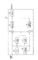
- FIG. 2 is a diagram showing an example of a functional block of the image coding apparatus 100 according to the present embodiment.
- the image coding device 100 includes an inter-prediction unit 111, an intra-prediction unit 112, a subtractor 121, an adder 122, a conversion / quantization unit 131, and an inverse conversion / inverse quantization. It has a unit 132, an encoding unit 140, an in-loop filter processing unit 150, and a frame buffer 160.
- the inter-prediction unit 111 is configured to generate a prediction signal by inter-prediction (inter-frame prediction).
- the inter-prediction unit 111 identifies and identifies the reference block included in the reference frame by comparing the frame to be encoded (hereinafter referred to as the target frame) with the reference frame stored in the frame buffer 160. It is configured to determine the motion vector for the reference block.
- the inter-prediction unit 111 is configured to generate a prediction signal included in the prediction block for each prediction block based on the reference block and the motion vector.
- the inter-prediction unit 111 is configured to output a prediction signal to the subtractor 121 and the adder 122.
- the reference frame is a frame different from the target frame.
- the intra prediction unit 112 is configured to generate a prediction signal by intra prediction (in-frame prediction).
- the intra prediction unit 112 is configured to specify a reference block included in the target frame and generate a prediction signal for each prediction block based on the specified reference block. Further, the intra prediction unit 112 is configured to output a prediction signal to the subtractor 121 and the adder 122.
- the reference block is a block referred to for the block to be predicted (hereinafter referred to as the target block).
- the reference block is a block adjacent to the target block.
- the subtractor 121 is configured to subtract the prediction signal from the input image signal and output the prediction residual signal to the conversion / quantization unit 131.
- the subtractor 121 is configured to generate a prediction residual signal, which is the difference between the prediction signal generated by the intra prediction or the inter prediction and the input image signal.
- the adder 122 adds a prediction signal to the prediction residual signal output from the inverse conversion / inverse quantization unit 132 to generate a pre-filter processing decoding signal, and the pre-filter processing decoding signal is combined with the intra prediction unit 112 and the input. It is configured to output to the loop filter processing unit 150.
- the pre-filtered decoding signal constitutes a reference block used by the intra prediction unit 112.
- the conversion / quantization unit 131 is configured to perform conversion processing of the predicted residual signal and acquire a coefficient level value. Further, the conversion / quantization unit 131 may be configured to quantize the coefficient level value.
- the conversion process is a process of converting the predicted residual signal into a frequency component signal.
- a base pattern (transformation matrix) corresponding to the discrete cosine transform (DCT) may be used, and a base pattern (transformation matrix) corresponding to the discrete sine transform (DST) may be used. May be used.
- the inverse conversion / inverse quantization unit 132 is configured to perform an inverse conversion process of the coefficient level value output from the conversion / quantization unit 131.
- the inverse conversion / inverse quantization unit 132 may be configured to perform inverse quantization of the coefficient level value prior to the inverse conversion process.
- the inverse conversion process and the inverse quantization are performed in the reverse procedure of the conversion process and the quantization performed by the conversion / quantization unit 131.
- the coding unit 140 is configured to encode the coefficient level value output from the conversion / quantization unit 131 and output the coded data.
- coding is entropy coding in which codes of different lengths are assigned based on the probability of occurrence of a coefficient level value.
- the coding unit 140 is configured to encode the control data used in the decoding process in addition to the coefficient level value.
- control data may include size data such as a coded block (CU: Coding Unit) size, a prediction block (PU: Precision Unit) size, and a conversion block (TU: Transfer Unit) size.
- CU Coding Unit
- PU prediction block
- TU Transfer Unit
- the in-loop filter processing unit 150 is configured to perform filter processing on the pre-filter processing decoding signal output from the adder 122 and output the post-filter processing decoding signal to the frame buffer 160.
- the filtering process is a deblocking filtering process that reduces the distortion that occurs at the boundary portion of the block (encoded block, prediction block, or conversion block).
- the frame buffer 160 is configured to store reference frames used by the inter-prediction unit 111.
- the decoded signal after the filter processing constitutes a reference frame used by the inter-prediction unit 111.
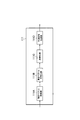
- FIG. 3 is a diagram showing an example of a functional block of the inter-prediction unit 111 of the image coding apparatus 100 according to the present embodiment.
- the inter-prediction unit 111 includes a motion vector search unit 111A, a motion vector coding unit 111B, a refinement unit 111C, and a prediction signal generation unit 111D.
- the inter-prediction unit 111 is an example of a prediction unit configured to generate a prediction signal included in a prediction block based on a motion vector.
- the motion vector search unit 111A is configured to identify the reference block included in the reference frame by comparing the target frame with the reference frame, and search for the motion vector for the specified reference block.
- the above-mentioned search process is performed on a plurality of reference frame candidates, and the reference frame and motion vector used for prediction in the prediction block are determined. Up to two reference frames and two motion vectors can be used for one block. The case where only one set of reference frame and motion vector is used for one block is called single prediction, and the case where two sets of reference frame and motion vector are used is called double prediction.
- L0 the first set will be referred to as L0
- L1 the second set will be referred to as L1.
- the motion vector search unit 111A is configured to determine the reference frame and the motion vector coding method.
- the coding method includes a merge mode described later, a Symmetric MVD mode described in Non-Patent Document 2, and the like.
- the reference frame determination method As for the motion vector search method, the reference frame determination method, and the reference frame and motion vector coding method determination method, known methods can be adopted, and details thereof will be omitted.
- the motion vector coding unit 111B is configured to encode the reference frame and motion vector information determined by the motion vector search unit 111A by using the coding method also determined by the motion vector search unit 111A.
- the merge list is a list in which a plurality of combinations of reference frames and motion vectors are listed. An index is assigned to each combination, and instead of individually encoding the reference frame and motion vector information, only the index is encoded and transmitted to the decoding side.
- the decoding side can decode the reference frame and motion vector information only from the index information.
- a known method can be adopted, so the details thereof will be omitted.
- the Symmetric MVD mode is a coding method that can be used only when performing bi-prediction in the block.
- the Symmetric MVD mode only the motion vector (difference motion vector) of L0 is coded out of the two (L0, L1) reference frames and the two motion vectors (L0, L1) that are the information to be transmitted to the decoding side. To become.
- the remaining motion vector of L1 and the information of the two reference frames are uniquely determined on the coding side and the decoding side by a predetermined method.
- the predicted motion vector which is the predicted value of the motion vector to be encoded
- the differential motion vector which is the difference value between the predicted motion vector and the motion vector to be actually encoded
- the code of the encoded difference motion vector of L0 is inverted as the difference motion vector of L1.
- the method described in Non-Patent Document 2 can be used.
- the refinement unit 111C is configured to perform a refinement process (for example, DMVR) for modifying the motion vector encoded by the motion vector coding unit 111B.
- a refinement process for example, DMVR
- the refinement unit 111C sets the search range with reference to the reference position specified by the motion vector encoded by the motion vector coding unit 111B, and corrects the search range with the smallest predetermined cost. It is configured to perform refinement processing that identifies the reference position and corrects the motion vector based on the correction reference position.
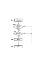
- FIG. 4 is a flowchart showing an example of the processing procedure of the refinement unit 111C.
- step S41 the refinement unit 111C determines whether or not the predetermined conditions for applying the refinement process are satisfied. When all the predetermined conditions are satisfied, this processing procedure proceeds to step S42. If any one of the predetermined conditions is not satisfied, the processing procedure proceeds to step S45 and ends the refining process.
- the predetermined condition includes the condition that the block is a block that performs double prediction.
- the predetermined condition may include the condition that the motion vector is encoded in the merge mode.
- the predetermined condition may include a condition that the motion vector is encoded in the Symmetric MVD mode.
- the predetermined condition includes a condition that the motion vector is encoded in the Symmetric MVD mode and the magnitude of the differential motion vector (MVD of L0) transmitted in the Symmetric MVD mode is within a preset threshold value. It may be.
- the magnitude of the differential motion vector can be defined, for example, by the absolute value of each of the horizontal and vertical components of the differential motion vector.
- the threshold value different threshold values may be used for the horizontal and vertical components of the motion vector, or a common threshold value may be used for the horizontal and vertical components. It is also possible to set the threshold value to 0. In this case, it means that the predicted motion vector and the encoded motion vector have the same value. Further, the threshold value may be defined by the minimum value and the maximum value. In this case, the predetermined condition includes a condition that the value or the absolute value of the differential motion vector is equal to or more than a predetermined minimum value and equal to or less than the maximum value.
- the predetermined condition may include a condition that the motion vector is encoded in the merge mode or the Symmetric MVD mode.
- the predetermined condition is that when the motion vector is encoded in the merge mode or the Symmetric MVD mode and encoded in the Symmetric MVD mode, the magnitude of the transmitted differential motion vector is a preset threshold value. It may include the condition that it is within.
- step S42 the refinement unit 111C generates a search image based on the information of the motion vector and the reference frame encoded by the motion vector coding unit 111B.
- the refinement unit 111C applies a filter to the pixel value of the reference frame to interpolate the pixel at the non-integer pixel position.
- the refinement unit 111C can reduce the amount of calculation by using the interpolation filter having a smaller number of taps than the interpolation filter used in the prediction signal generation unit 111D described later.
- the refinement unit 111C can interpolate pixel values at non-integer pixel positions by bilinear interpolation.
- step S43 the refinement unit 111C performs a search with integer pixel accuracy using the search image generated in step S42.
- the integer pixel accuracy means to search only the points at the integer pixel interval with reference to the motion vector encoded by the motion vector coding unit 111B.
- the refinement unit 111C determines the corrected motion vector at the integer pixel interval position by the search in step S42.
- a known method can be used as the search method.
- the refinement unit 111C can also search by a method of searching only a point where the difference motion vector on the L0 side and the L1 side is a combination in which only the sign is inverted.
- the search in step S43 there is a possibility that the value will be the same as the motion vector before the search.
- step S44 the refinement unit 111C searches for a motion vector with non-integer pixel accuracy, using the motion vector after correction with integer pixel accuracy determined in step S43 as an initial value.
- a motion vector search method a known method can be used.
- the refinement unit 111C can also determine a vector with non-integer pixel accuracy by using a parabolic fitting or the like parametric model as an input of the result of step S43 without actually performing a search.
- step S44 the refinement unit 111C determines the motion vector after correction with non-integer pixel accuracy, and then proceeds to step S45 to end the refinement process.
- the expression of the modified motion vector with non-integer pixel accuracy is used, but the search result in step S44 may result in the same value as the motion vector with integer pixel accuracy obtained in step S43. There is also.
- the refinement unit 111C may divide a block larger than a predetermined threshold into smaller subblocks and execute the refinement process for each subblock. For example, the refinement unit 111C sets the execution unit of the refinement process to 16 ⁇ 16 pixels, and when the size of the block in the horizontal direction or the vertical direction is larger than 16 pixels, it is divided so as to be 16 pixels or less. can do. At this time, as the motion vector that serves as the reference for the refinement process, the motion vector of the block encoded by the motion vector coding unit 111B is used for all the subblocks in the same block.
- the refinement unit 111C may execute all the procedures shown in FIG. 4 for each subblock. Further, the refinement unit 111C may process only a part of the process of FIG. 4 for each subblock. Specifically, the refinement unit 111C may process steps S41 and S42 in FIG. 4 for each block, and process only steps S43 and S44 for each subblock.
- the prediction signal generation unit 111D is configured to generate a prediction signal based on the modified motion vector output from the refinement unit 111C.
- the prediction signal generation unit 111D determines whether or not to perform BDOF processing for each block based on the information calculated in the process of the above-mentioned refinement processing (for example, search cost). It is configured as follows.
- the prediction signal generation unit 111D is configured to generate a prediction signal based on the motion vector encoded by the motion vector coding unit 111B when the motion vector is not modified.
- the prediction signal generation unit 111D is configured to generate a prediction signal based on the motion vector corrected by the refinement unit 111C when the motion vector is corrected.
- FIG. 5 is a flowchart showing an example of the processing procedure of the prediction signal generation unit 111D.
- the process of the prediction signal generation unit 111D is also executed in sub-block units.
- the word block in the following description can be appropriately read as a subblock.
- step S51 the prediction signal generation unit 111D generates a prediction signal.
- the prediction signal generation unit 111D takes a motion vector encoded by the motion vector coding unit 111B or a motion vector encoded by the refinement unit 111C as an input, and the position pointed to by the motion vector is a non-integer.
- a filter is applied to the pixel value of the reference frame to interpolate the pixel at the non-integer pixel position.
- a horizontal / vertical separable filter with a maximum of 8 taps disclosed in Non-Patent Document 3 can be applied.
- the block When the block is a block that performs bi-prediction, it is based on the first (hereinafter referred to as L0) reference frame and motion vector prediction signal and the second (hereinafter referred to as L1) reference frame and motion vector. Generate both prediction signals.
- step S52 the prediction signal generation unit 111D confirms whether or not the application conditions of BDOF (Bi-Directional Optical Flow) described later are satisfied.
- BDOF Bi-Directional Optical Flow
- the applicable condition includes at least the condition that the block is a block that performs bi-prediction. Further, the applicable condition may include a condition that the motion vector of the block is not encoded in the Symmetric MVD mode as described in Non-Patent Document 1.
- the application condition is that the motion vector of the block is not encoded in the Symmetric MVD mode, or when it is encoded in the Symmetric MVD mode, the size of the differential motion vector to be transmitted is preset. It may include the condition that it is within the threshold value.
- the magnitude of the differential motion vector can be determined by the same method as in step S41 described above.
- the threshold value can be set to 0 in the same manner as in step S41 described above.
- step S55 the prediction signal generation unit 111D outputs the prediction signal generated in step S51 as the final prediction signal.
- step S53 this processing procedure determines whether or not to actually execute the BDOF processing of step S54 for the block satisfying the applicable conditions.
- the prediction signal generation unit 111D calculates the absolute value difference sum of the prediction signal of L0 and the prediction signal of L1, and if the value is equal to or less than a predetermined threshold value, BDOF processing is not performed. Make a judgment.
- the prediction signal generation unit 111D can also use the result of the refinement processing depending on whether or not the BDOF is applied to the block for which the refinement process is executed by the refinement unit 111C.
- the prediction signal generation unit 111D can determine that the BDOF is not applied.
- a threshold value is set to "0" for both the horizontal and vertical components, it is determined that the BDOF is not applied when the motion vector does not change as a result of the refinement process as a result of the refinement process. It becomes equivalent.
- the prediction signal generation unit 111D uses the search cost calculated in the process of the above-mentioned refinement processing (for example, the absolute value difference sum of the pixel value of the reference block on the L0 side and the pixel value of the reference block on the L1 side). , It is also possible to determine whether or not to apply BDOF.
- the absolute value difference sum is used as the search cost as the search cost
- it may be an index value for determining the similarity between image signals, such as the sum of absolute value differences between signals after removing the local average value and the sum of squared errors.
- the prediction signal generation unit 111D determines that the absolute value difference sum of the search points at which the search cost (absolute value difference sum) is minimized is smaller than a predetermined threshold value. , It can be determined that the BDOF is not applied.
- the prediction signal generation unit 111D can also determine the suitability of the BFOF process by combining the method using the change of the motion vector before and after the refinement process described above and the method using the search cost of the refinement process described above. ..
- the prediction signal generation unit 111D determines that the BDOF process is not applied when the difference between the motion vectors before and after the refinement process is equal to or less than a predetermined threshold value and the search cost of the refinement process is equal to or less than a predetermined threshold value. be able to.
- the motion vector before the refinement process indicates the above-mentioned search cost. It is the sum of the absolute value differences between the reference blocks.
- the prediction signal generation unit 111D may determine by the method based on the result of the refinement processing in the block in which the refinement processing is executed, and by the method by the absolute value difference sum in the other blocks.
- the prediction signal generation unit 111D is obtained from the result of the refinement processing without newly performing the processing of calculating the absolute value difference sum of the prediction signal on the L0 side and the prediction signal on the L1 side as described above. It is also possible to use only the information to determine the suitability of the BDOF. In this case, in step S53, the prediction signal generation unit 111D determines that the BDOF is always applied to the block for which the refinement process has not been executed.
- the coding efficiency is improved by using the result of the refinement processing and preventing the BDOF processing from being executed in the block where the effect of the BDOF processing is presumed to be low. It is possible to reduce the processing time of the entire image while maintaining it.
- the determination process itself using the result of the above-mentioned refinement process is executed inside the refinement unit 111C, and the information indicating the result is transmitted to the prediction signal generation unit 111D, so that the prediction signal generation unit 111D , It is also possible to determine the suitability of BDOF processing.
- the motion vector and the value of the search cost before and after the refinement process are determined, and if the condition that the BDOF is not applied is satisfied, the value is "1". Is prepared, a flag that becomes "0" when is not applied, and the prediction signal generation unit 111D can determine the suitability of BDOF by referring to the value of such a flag.
- step S52 and step S53 have been described as different steps, but it is also possible to make determinations in steps S52 and S53 at the same time.
- step S55 For the block determined not to apply BDOF in the above determination, this processing procedure proceeds to step S55. For the other blocks, this processing procedure proceeds to step S54.
- step S54 the prediction signal generation unit 111D executes BDOF processing. Since a known method can be used for the BDOF processing itself, detailed description thereof will be omitted. After the BDOF process is performed, the process moves to step S55 to end the process.
- FIG. 6 is a diagram showing an in-loop filter processing unit 150 according to the present embodiment.
- the in-loop filter processing unit 150 includes a target block boundary detection unit 151, an adjacent block boundary detection unit 152, a boundary strength determination unit 153, a filter determination unit 154, and a filter processing unit 155. Have.
- the configuration with "A” at the end is the configuration related to the deblocking filter processing for the vertical block boundary
- the configuration with "B” at the end is the configuration for the horizontal block boundary. This is a configuration related to deblocking filtering.
- the following is an example of a case where the deblocking filter processing is performed on the vertical block boundary and then the deblocking filter processing is performed on the horizontal block boundary.
- the deblocking filter process may be applied to the coded block, the predicted block, or the converted block. Further, it may be applied to a sub-block obtained by dividing each of the above blocks. That is, the target block and the adjacent block may be a coded block, a prediction block, a conversion block, or a subblock obtained by dividing them.
- the definition of the sub-block includes the sub-block described as the processing unit of the refinement unit 111C and the prediction signal generation unit 111D.
- the block described below can be read as a subblock as appropriate.
- the target block boundary detection unit 151A is configured to detect the boundary of the target block based on the control data indicating the block size of the target block.
- the adjacent block boundary detection unit 152A is configured to detect the boundary of the adjacent block based on the control data indicating the block size of the adjacent block.
- the boundary strength determination unit 153A is configured to determine the boundary strength of the block boundary between the target block and the adjacent block.
- boundary strength determination unit 153A may be configured to determine the boundary strength of the block boundary based on the control data indicating whether or not the target block and the adjacent block are intra prediction blocks.
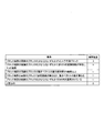
- the boundary strength determination unit 153A when at least one block of the target block and the adjacent block is an intra prediction block (that is, at least one of the blocks on both sides of the block boundary is intra. In the case of a prediction block), it may be configured to determine that the boundary strength of the block boundary is "2".
- the boundary strength determination unit 153A is based on control data indicating whether or not the target block and the adjacent block include a non-zero (zero) orthogonal conversion coefficient and whether or not the block boundary is the boundary of the conversion block. It may be configured to determine the boundary strength of the block boundary.
- the boundary strength determination unit 153A when at least one block of the target block and the adjacent block includes a non-zero orthogonal conversion coefficient and the block boundary is the boundary of the conversion block. It is configured to determine that the boundary strength of the block boundary is "1" (ie, if at least one of the blocks on either side of the block boundary has a non-zero conversion factor and is a TU boundary). May be.
- the boundary strength determination unit 153A determines the boundary strength of the block boundary based on the control data indicating whether or not the absolute value of the difference between the motion vectors of the target block and the adjacent block is equal to or greater than the threshold value (for example, 1 pixel). It may be configured to do so.
- the threshold value for example, 1 pixel
- the boundary strength determination unit 153A has a case where the absolute value of the difference between the motion vectors of the target block and the adjacent block is equal to or more than a threshold value (for example, 1 pixel) (that is, blocks on both sides of the block boundary).
- the boundary strength of the block boundary may be determined to be "1" when the absolute value of the difference between the motion vectors of is equal to or greater than the threshold value (for example, 1 pixel).
- the boundary strength determination unit 153A is configured to determine the boundary strength of the block boundary based on the control data indicating whether or not the reference blocks referred to in the prediction of the motion vectors of the target block and the adjacent block are different. You may.
- the boundary strength determination unit 153A has a case where the reference blocks referred to in the prediction of the motion vector of the target block and the adjacent block are different (that is, the reference images are different in the blocks on both sides of the block boundary). ) May be configured to determine that the boundary strength of the block boundary is "1".
- the boundary strength determination unit 153A may be configured to determine the boundary strength of the block boundary based on control data indicating whether or not the numbers of motion vectors of the target block and the adjacent block are different.
- the boundary strength determination unit 153A blocks when the numbers of motion vectors of the target block and the adjacent block are different (that is, when the numbers of motion vectors are different in the blocks on both sides of the block boundary). It may be configured to determine that the boundary strength of the boundary is "1".
- the boundary strength determination unit 153A may be configured to determine the boundary strength of the block boundary depending on whether or not the refinement processing by the refinement unit 111C is applied to the target block and the adjacent block.
- the boundary strength of the block boundary is "1". It may be configured to determine that.
- the boundary strength determination unit 153A may determine that "the refinement process has been applied" when all the predetermined conditions in step S41 of FIG. 4 are satisfied in the block. Further, a flag indicating the determination result of step S41 in FIG. 4 may be prepared, and the boundary strength determination unit 153A may be configured to determine whether or not the refinement process is applied based on the value of the flag.
- the boundary strength determination unit 153A determines that the boundary strength of the block boundary is "1" when at least one of the target block or the adjacent block is a block to which the refinement processing by the refinement unit 111C is applied. It may be configured to do so.
- the boundary strength determination unit 153A may be configured to determine that the boundary strength of the block boundary is "1" when the boundary is a sub-block boundary in the refinement process by the refinement unit 111C. Good.
- boundary strength determination unit 153A is configured to determine that the boundary strength of the block boundary is "1" when DMVR is applied to at least one of the blocks on both sides of the block boundary. Good.
- the boundary strength determination unit 153A may be configured to determine that the boundary strength of the block boundary is "0" when none of the above conditions are satisfied.
- the above-mentioned boundary strength determination method may be determined by a common method for the luminance signal and the color difference signal, or may be determined by using some different conditions.
- the above-mentioned conditions relating to the refinement process may be applied to both the luminance signal and the color difference signal, or may be applied only to the luminance signal or only the color difference signal.
- a flag for controlling whether or not the result of the refinement process is taken into consideration when determining the boundary strength may be provided in a header called SPS (Sequence Parameter Set) or PPS (Picture Parameter Set).
- the filter determination unit 154A is configured to determine the type of filter processing (for example, deblocking filter processing) applied to the block boundary.
- the filter determination unit 154A determines whether or not to apply the filter processing to the block boundary based on the boundary strength of the block boundary, the quantization parameter included in the target block and the adjacent block, and the weak filter processing and the strong. It may be configured to determine which of the filterings to apply.
- the filter determination unit 154A may be configured to determine that the filter processing is not applied when the boundary strength of the block boundary is "0".
- the filter processing unit 155A is configured to perform processing on the pre-deblocking image based on the determination of the filter determination unit 154A.
- the processing for the image before deblocking includes no filtering, weak filtering, strong filtering, and the like.
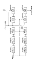
- FIG. 8 is a diagram showing an example of a functional block of the image decoding apparatus 200 according to the present embodiment.
- the image decoding device 200 includes a decoding unit 210, an inverse conversion / inverse quantization unit 220, an adder 230, an inter-prediction unit 241 and an intra-prediction unit 242, and an in-loop filter processing unit. It has 250 and a frame buffer 260.
- the decoding unit 210 is configured to decode the coded data generated by the image coding device 100 and decode the coefficient level value.
- the decoding is the entropy decoding in the reverse procedure of the entropy coding performed by the coding unit 140.
- the decoding unit 210 may be configured to acquire control data by decoding the encoded data.
- control data may include size data such as a coded block size, a predicted block size, and a conversion block size.
- the inverse conversion / inverse quantization unit 220 is configured to perform an inverse conversion process of the coefficient level value output from the decoding unit 210.
- the inverse conversion / inverse quantization unit 220 may be configured to perform inverse quantization of the coefficient level value prior to the inverse conversion process.
- the inverse conversion process and the inverse quantization are performed in the reverse procedure of the conversion process and the quantization performed by the conversion / quantization unit 131.
- the adder 230 adds a prediction signal to the prediction residual signal output from the inverse conversion / inverse quantization unit 220 to generate a pre-filter processing decoding signal, and uses the pre-filter processing decoding signal as an intra prediction unit 242 and an in-loop. It is configured to output to the filter processing unit 250.
- the pre-filtered decoding signal constitutes a reference block used in the intra prediction unit 242.
- the inter-prediction unit 241 is configured to generate a prediction signal by inter-prediction (inter-frame prediction).
- the inter-prediction unit 241 is configured to generate a prediction signal for each prediction block based on the motion vector decoded from the coded data and the reference signal included in the reference frame.
- the inter-prediction unit 241 is configured to output a prediction signal to the adder 230.
- the intra prediction unit 242 is configured to generate a prediction signal by intra prediction (in-frame prediction).
- the intra prediction unit 242 is configured to specify a reference block included in the target frame and generate a prediction signal for each prediction block based on the specified reference block.
- the intra prediction unit 242 is configured to output a prediction signal to the adder 230.
- the in-loop filter processing unit 250 performs filter processing on the pre-filter processing decoding signal output from the adder 230, and outputs the post-filter processing decoding signal to the frame buffer 260. It is configured to do.
- the filtering process is a deblocking filtering process that reduces the distortion generated at the boundary portion of blocks (encoded blocks, prediction blocks, conversion blocks, or sub-blocks obtained by dividing them).
- the frame buffer 260 is configured to store reference frames used by the inter-prediction unit 241.
- the decoded signal after the filter processing constitutes a reference frame used by the inter-prediction unit 241.
- FIG. 9 is a diagram showing an example of a functional block of the inter-prediction unit 241 according to the present embodiment.
- the inter-prediction unit 241 has a motion vector decoding unit 241B, a refinement unit 241C, and a prediction signal generation unit 241D.
- the inter prediction unit 241 is an example of a prediction unit configured to generate a prediction signal included in the prediction block based on a motion vector.
- the motion vector decoding unit 241B is configured to acquire the motion vector by decoding the control data received from the image coding device 100.
- the refinement unit 241C is configured to execute a refinement process for modifying the motion vector, similarly to the refinement unit 111C.
- the prediction signal generation unit 241D is configured to generate a prediction signal based on a motion vector, similarly to the prediction signal generation unit 111D.
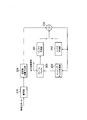
- FIG. 10 is a diagram showing an in-loop filter processing unit 250 according to the present embodiment.
- the in-loop filter processing unit 250 includes a target block boundary detection unit 251, an adjacent block boundary detection unit 252, a boundary strength determination unit 253, a filter determination unit 254, and a filter processing unit 255. Have.
- the configuration with "A” at the end is the configuration related to the deblocking filter processing for the vertical block boundary
- the configuration with "B” at the end is the configuration for the horizontal block boundary. This is a configuration related to deblocking filtering.
- the deblocking filter process may be applied to the coded block, the predicted block, or the converted block. Moreover, it may be applied to the sub-block which divided each block mentioned above. That is, the target block and the adjacent block may be a coded block, a prediction block, a conversion block, or a subblock obtained by dividing them.
- the target block boundary detection unit 251A is configured to detect the boundary of the target block based on the control data indicating the block size of the target block, similarly to the target block boundary detection unit 151A.
- the adjacent block boundary detection unit 252A is configured to detect the boundary of the adjacent block based on the control data indicating the block size of the adjacent block.
- the boundary strength determination unit 253A is configured to determine the boundary strength of the block boundary between the target block and the adjacent block, similarly to the boundary strength determination unit 153A.
- the method for determining the boundary strength of the block boundary is as described above.
- the filter determination unit 254A is configured to determine the type of deblocking filter processing applied to the block boundary, similarly to the filter determination unit 154A.
- the method for determining the type of deblocking filtering is as described above.
- the filter processing unit 255A is configured to perform processing on the image before deblocking based on the determination of the filter determination unit 254A.
- the processing for the image before deblocking includes no filtering, weak filtering, strong filtering, and the like.
- the refinement units 111C and 241C are used in the blocks adjacent to the boundary. Consider whether the refinement process has been applied.
- the boundary strength of the boundary is set to 1.
- the filter determination units 154 and 254 consider whether or not a deblocking filter is applied to the block boundary in consideration of parameters such as quantization parameters, and the deblocking filter. Determine the type.
- a deblocking filter can be applied, block noise can be suppressed, and subjective image quality can be improved.
- Patent Document 1 discloses a technique for omitting the application of a deblocking filter based on syntax information such as whether the block is in skip mode.
- Patent Document 2 discloses a technique of omitting the application of the deblocking filter by using the quantization parameter.
- the suitability of the refinement process is not considered.
- One of the problems solved by the present invention is that the corrected motion vector value cannot be used for determining the application of the deblocking filter in the refinement process in which the motion vector value decoded from the syntax is corrected on the decoding side. In this case, it is a problem peculiar to the refinement process that the application judgment cannot be made appropriately.
- a motion vector that is a reference of the process is encoded in the Symmetric MVD mode. Consider whether or not it has been done.
- the code amount related to the differential motion vector can be reduced by making the differential motion vector transmitted in the Symmetric MVD mode as small as possible.
- the difference motion vector is a specific value (0, etc.)
- the flag is transmitted, and in the case of other values, the difference value is directly encoded. Even if the difference between the motion vectors corrected by is small, the effect of reducing the code amount may be large.
- a motion vector that is a reference of the refinement process is encoded in the Symmetric MVD mode, and the value of the difference motion vector is equal to or less than a predetermined threshold value.
- the motion vector of the block is encoded in the Symmetric MVD mode under the application conditions of BDOF processing in the prediction signal generation units 111D and 241D, and the value of the differential motion vector is equal to or less than a predetermined threshold value.
- the condition it is possible to implicitly switch whether to apply the BDOF processing depending on the value of the differential motion vector.
- the result of the refinement processing is taken into consideration in determining whether or not the BDOF processing is executed in the prediction signal generation units 111D and 241D.
- the determination is performed using the absolute value difference value of the prediction signals of L0 and L1, but instead, the process of calculating the absolute value difference is performed by performing the determination based on the result of the refinement process. It can be reduced.
- image coding device 100 and image decoding device 200 may be realized by a program that causes a computer to execute each function (each process).
- the present invention has been described by taking application to the image coding device 100 and the image decoding device 200 as an example, but the present invention is not limited to this, and the coding device and The same applies to a coding / decoding system having each function of the decoding device.
- the deblocking filter is appropriately applied to the boundary of the refined block to suppress block noise.
- the subjective image quality can be improved.
Landscapes
- Engineering & Computer Science (AREA)
- Multimedia (AREA)
- Signal Processing (AREA)
- Compression Or Coding Systems Of Tv Signals (AREA)
Abstract
画像復号装置200は、符号化データから動きベクトルを復号するように構成されている動きベクトル復号部241Bと、復号された動きベクトルを修正する洗練化処理を行うように構成されている洗練化部241Cと、対象ブロックと隣接ブロックとのブロック境界の境界強度を判定するように構成されている境界強度判定部253と、ブロック境界に適用するフィルタ処理の種類を決定するように構成されているフィルタ決定部254とを有し、境界強度判定部253は、対象ブロック及び隣接ブロックに対する洗練化処理の適否に基づいて境界強度を判定するように構成されている。
Description
本発明は、画像復号装置、画像復号方法及びプログラムに関する。
従来、Decoder-side motion vector refinement(DMVR:復号側動きベクトル洗練化処理) という技術に関して、洗練化処理後の動きベクトルをデブロッキングフィルタの適用判定に用いる技術が開示されている(例えば、非特許文献1参照)。
また、ハードウェア設計上の都合で、洗練化処理後の動きベクトルをデブロッキングフィルタの適用判定に用いることが難しい場合、かかる洗練化処理を実施するブロックについても、洗練化処理前の動きベクトルをデブロッキングフィルタの適用判定に用いる技術が開示されている。
CE9: Results of DMVR related Tests CE9.2.1 and CE9.2.2、JVET-M0147
CE4-related: Simplified symmetric MVD based on CE4.4.3、JVET-M0444
しかしながら、上述した技術では、洗練化処理前の動きベクトルをデブロッキングフィルタの適用判定に用いる場合、洗練化処理によって隣接するブロック間で動きベクトルの値が異なる場合にも、デブロッキングフィルタが適用されない可能性があり、かかる隣接するブロックの境界においてブロックノイズが発生してしまう可能性があるという問題点があった。
そこで、本発明は、上述の課題に鑑みてなされたものであり、洗練化処理後の動きベクトルをデブロッキングフィルタの適用判定に用いることができない場合であっても、洗練化処理を行ったブロックの境界に適切にデブロッキングフィルタを適用し、ブロックノイズを抑制して主観画質を向上させることができる画像復号装置、画像復号方法及びプログラムを提供することを目的とする。
本発明の第1の特徴は、画像復号装置であって、符号化データから動きベクトルを復号するように構成されている動きベクトル復号部と、復号された前記動きベクトルを修正する洗練化処理を行うように構成されている洗練化部と、対象ブロックと隣接ブロックとのブロック境界の境界強度を判定するように構成されている境界強度判定部と、前記ブロック境界に適用するフィルタ処理の種類を決定するように構成されているフィルタ決定部とを有し、前記境界強度判定部は、前記対象ブロック及び隣接ブロックに対する前記洗練化処理の適否に基づいて、前記境界強度を判定するように構成されていることを要旨とする。
本発明の第2の特徴は、画像復号装置であって、符号化データから動きベクトルを復号するように構成されている動きベクトル復号部と、復号された前記動きベクトルを修正する洗練化処理を行うように構成されている洗練化部とを有し、前記洗練化部は、所定条件を満たすブロックに対してのみ前記洗練化処理を行うように構成されており、前記所定条件は、前記動きベクトルが、Symmetric MVDモードで符号化されていることという条件であることを要旨とする。
本発明の第3の特徴は、画像復号装置であって、符号化データから動きベクトルを復号するように構成されている動きベクトル復号部と、復号された前記動きベクトルを修正する洗練化処理を行うように構成されている洗練化部とを有し、前記洗練化部は、所定条件を満たすブロックに対してのみ前記洗練化処理を行うように構成されており、前記所定条件は、前記動きベクトルが、Symmetric MVDモードで符号化されており、前記Symmetric MVDモードにおいて伝送される差分動きベクトルの大きさが予め設定された閾値以内であるという条件であることを要旨とする。
本発明の第4の特徴は、符号化データから動きベクトルを復号する工程Aと、復号された前記動きベクトルを修正する洗練化処理を行う工程Bと、対象ブロックと隣接ブロックとのブロック境界の境界強度を判定する工程Cと、前記ブロック境界に適用するフィルタ処理の種類を決定する工程Dとを有し、前記工程Cにおいて、前記対象ブロック及び隣接ブロックに対する前記洗練化処理の適否に基づいて、前記境界強度を判定することを要旨とする。
本発明の第5の特徴は、画像復号装置で用いるプログラムであって、コンピュータに、符号化データから動きベクトルを復号する工程Aと、復号された前記動きベクトルを修正する洗練化処理を行う工程Bと、対象ブロックと隣接ブロックとのブロック境界の境界強度を判定する工程Cと、前記ブロック境界に適用するフィルタ処理の種類を決定する工程Dとを実行させ、前記工程Cにおいて、前記対象ブロック及び隣接ブロックに対する前記洗練化処理の適否に基づいて、前記境界強度を判定することを要旨とする。
本発明によれば、洗練化処理後の動きベクトルをデブロッキングフィルタの適用判定に用いることができない場合であっても、洗練化処理を行ったブロックの境界に適切にデブロッキングフィルタを適用し、ブロックノイズを抑制して主観画質を向上させることができる画像復号装置、画像復号方法及びプログラムを提供することができる。
以下、本発明の実施の形態について、図面を参照しながら説明する。なお、以下の実施形態における構成要素は、適宜、既存の構成要素等との置き換えが可能であり、また、他の既存の構成要素との組み合わせを含む様々なバリエーションが可能である。したがって、以下の実施形態の記載をもって、特許請求の範囲に記載された発明の内容を限定するものではない。
(第1実施形態)
以下、図1~図10を参照して、本発明の第1実施形態に係る画像処理システム10について説明する。図1は、本実施形態に係る実施形態に係る画像処理システム10を示す図である。
以下、図1~図10を参照して、本発明の第1実施形態に係る画像処理システム10について説明する。図1は、本実施形態に係る実施形態に係る画像処理システム10を示す図である。
図1に示すように、画像処理システム10は、画像符号化装置100及び画像復号装置200を有する。
画像符号化装置100は、入力画像信号を符号化することによって符号化データを生成するように構成されている。画像復号装置200は、符号化データを復号することによって出力画像信号を生成するように構成されている。
ここで、かかる符号化データは、画像符号化装置100から画像復号装置200に対して伝送路を介して送信されてもよい。また、符号化データは、記憶媒体に格納された上で、画像符号化装置100から画像復号装置200に提供されてもよい。
(画像符号化装置100)
以下、図2を参照して、本実施形態に係る画像符号化装置100について説明する。図2は、本実施形態に係る画像符号化装置100の機能ブロックの一例について示す図である。
以下、図2を参照して、本実施形態に係る画像符号化装置100について説明する。図2は、本実施形態に係る画像符号化装置100の機能ブロックの一例について示す図である。
図2に示すように、画像符号化装置100は、インター予測部111と、イントラ予測部112と、減算器121と、加算器122と、変換・量子化部131と、逆変換・逆量子化部132と、符号化部140と、インループフィルタ処理部150と、フレームバッファ160とを有する。
インター予測部111は、インター予測(フレーム間予測)によって予測信号を生成するように構成されている。
具体的には、インター予測部111は、符号化対象のフレーム(以下、対象フレーム)とフレームバッファ160に格納される参照フレームとの比較によって、参照フレームに含まれる参照ブロックを特定し、特定された参照ブロックに対する動きベクトルを決定するように構成されている。
また、インター予測部111は、参照ブロック及び動きベクトルに基づいて予測ブロックに含まれる予測信号を予測ブロック毎に生成するように構成されている。インター予測部111は、予測信号を減算器121及び加算器122に出力するように構成されている。ここで、参照フレームは、対象フレームとは異なるフレームである。
イントラ予測部112は、イントラ予測(フレーム内予測)によって予測信号を生成するように構成されている。
具体的には、イントラ予測部112は、対象フレームに含まれる参照ブロックを特定し、特定された参照ブロックに基づいて予測信号を予測ブロック毎に生成するように構成されている。また、イントラ予測部112は、予測信号を減算器121及び加算器122に出力するように構成されている。
ここで、参照ブロックは、予測対象のブロック(以下、対象ブロック)について参照されるブロックである。例えば、参照ブロックは、対象ブロックに隣接するブロックである。
減算器121は、入力画像信号から予測信号を減算し、予測残差信号を変換・量子化部131に出力するように構成されている。ここで、減算器121は、イントラ予測又はインター予測によって生成される予測信号と入力画像信号との差分である予測残差信号を生成するように構成されている。
加算器122は、逆変換・逆量子化部132から出力される予測残差信号に予測信号を加算してフィルタ処理前復号信号を生成し、かかるフィルタ処理前復号信号をイントラ予測部112及びインループフィルタ処理部150に出力するように構成されている。
ここで、フィルタ処理前復号信号は、イントラ予測部112で用いる参照ブロックを構成する。
変換・量子化部131は、予測残差信号の変換処理を行うとともに、係数レベル値を取得するように構成されている。さらに、変換・量子化部131は、係数レベル値の量子化を行うように構成されていてもよい。
ここで、変換処理は、予測残差信号を周波数成分信号に変換する処理である。かかる変換処理では、離散コサイン変換(DCT;Discrete Cosine Transform)に対応する基底パターン(変換行列)が用いられてもよく、離散サイン変換(DST;Discrete Sine Transform)に対応する基底パターン(変換行列)が用いられてもよい。
逆変換・逆量子化部132は、変換・量子化部131から出力される係数レベル値の逆変換処理を行うように構成されている。ここで、逆変換・逆量子化部132は、逆変換処理に先立って、係数レベル値の逆量子化を行うように構成されていてもよい。
ここで、逆変換処理及び逆量子化は、変換・量子化部131で行われる変換処理及び量子化とは逆の手順で行われる。
符号化部140は、変換・量子化部131から出力された係数レベル値を符号化し、符号化データを出力するように構成されている。
ここで、例えば、符号化は、係数レベル値の発生確率に基づいて異なる長さの符号を割り当てるエントロピー符号化である。
また、符号化部140は、係数レベル値に加えて、復号処理で用いる制御データを符号化するように構成されている。
ここで、制御データは、符号化ブロック(CU:Coding Unit)サイズ、予測ブロック(PU:Prediction Unit)サイズ、変換ブロック(TU:Transform Unit)サイズ等のサイズデータを含んでもよい。
インループフィルタ処理部150は、加算器122から出力されるフィルタ処理前復号信号に対してフィルタ処理を行うとともに、フィルタ処理後復号信号をフレームバッファ160に出力するように構成されている。
ここで、例えば、フィルタ処理は、ブロック(符号化ブロック、予測ブロック又は変換ブロック)の境界部分で生じる歪みを減少するデブロッキングフィルタ処理である。
フレームバッファ160は、インター予測部111で用いる参照フレームを蓄積するように構成されている。
ここで、フィルタ処理後復号信号は、インター予測部111で用いる参照フレームを構成する。
(インター予測部111)
以下、図3を参照して、本実施形態に係る画像符号化装置100のインター予測部111について説明する。図3は、本実施形態に係る画像符号化装置100のインター予測部111の機能ブロックの一例について示す図である。
以下、図3を参照して、本実施形態に係る画像符号化装置100のインター予測部111について説明する。図3は、本実施形態に係る画像符号化装置100のインター予測部111の機能ブロックの一例について示す図である。
図3に示すように、インター予測部111は、動きベクトル探索部111Aと、動きベクトル符号化部111Bと、洗練化部111Cと、予測信号生成部111Dとを有する。
インター予測部111は、動きベクトルに基づいて予測ブロックに含まれる予測信号を生成するように構成されている予測部の一例である。
動きベクトル探索部111Aは、対象フレームと参照フレームとの比較によって、参照フレームに含まれる参照ブロックを特定し、特定された参照ブロックに対する動きベクトルを探索するように構成されている。
また、上述の探索処理を複数の参照フレーム候補に対して行い、当該予測ブロックで予測に用いる参照フレーム及び動きベクトルを決定する。参照フレーム及び動きベクトルは、一つのブロックに対して最大二つずつ用いることができる。一つのブロックに対して参照フレームと動きベクトルを一組のみ用いる場合を片予測と呼び、参照フレームと動きベクトルを二組用いる場合を双予測と呼ぶ。以降、一組目をL0と呼び、二組目をL1と呼ぶ。
更に、動きベクトル探索部111Aは、参照フレーム及び動きベクトルの符号化方法を決定するように構成されている。符号化方法には、参照フレーム及び動きベクトルの情報をそれぞれ伝送する通常の方法に加え、後述するマージモードや非特許文献2に記載のSymmetric MVDモード等がある。
なお、動きベクトルの探索方法、参照フレームの決定方法及び参照フレーム及び動きベクトルの符号化方法の決定方法については、既知の手法を採用することが可能であるため、その詳細については省略する。
動きベクトル符号化部111Bは、動きベクトル探索部111Aで決定した参照フレームと動きベクトルの情報を、同じく動きベクトル探索部111Aで決定した符号化方法を用いて符号化するように構成されている。
当該ブロックの符号化方法がマージモードの場合、初めに、当該ブロックに対するマージリストを作成する。マージリストは、参照フレームと動きベクトルとの組み合わせが複数列挙されたリストである。各組み合わせには、インデックスが振られており、参照フレーム及び動きベクトルの情報を個別に符号化する代わりに、前記のインデックスのみを符号化し、復号側に伝送する。符号化側と復号側とでマージリストの作成方法を共通化しておくことで、復号側ではインデックス情報のみから参照フレームと動きベクトルの情報を復号することができる。マージリストの作成方法については、既知の手法を採用することが可能であるため、その詳細については省略する。
Symmetric MVDモードは、当該ブロックで双予測を行う場合にのみ使用可能な符号化方法である。Symmetric MVDモードでは、復号側に伝送すべき情報である二つ(L0、L1)の参照フレーム及び二つ(L0、L1)の動きベクトルのうち、L0の動きベクトル(差分動きベクトル)のみを符号化する。残りのL1の動きベクトル及び二つの参照フレームの情報については、予め決められた方法によって符号化側及び復号側でそれぞれ一意に決定する。
動きベクトル情報の符号化については、初めに符号化対象動きベクトルの予測値である予測動きベクトルを生成し、予測動きベクトルと実際に符号化したい動きベクトルとの差分値である差分動きベクトルを符号化する。
Symmetric MVDモードでは、L1の差分動きベクトルとして、符号化されたL0の差分動きベクトルの符号を反転したものを用いる。具体的な方法については、例えば、非特許文献2に記載されている方法を用いることができる。
洗練化部111Cは、動きベクトル符号化部111Bで符号化された動きベクトルを修正する洗練化処理(例えば、DMVR)を行うように構成されている。
具体的には、洗練化部111Cは、動きベクトル符号化部111Bで符号化された動きベクトルによって特定される参照位置を基準として探索範囲を設定し、探索範囲の中から所定コストが最も小さい修正参照位置を特定し、修正参照位置に基づいて動きベクトルを修正する洗練化処理を行うように構成されている。
図4は、洗練化部111Cの処理手順の一例を示すフローチャートである。
図4に示すように、ステップS41において、洗練化部111Cは、洗練化処理を適用するための所定条件が満足されているかどうかについて判定する。所定条件が全て満足されている場合に、本処理手順は、ステップS42へ進む。所定条件のどれか一つでも満足されていない場合は、本処理手順は、ステップS45へ進み、洗練化処理を終了する。
ここで、所定条件は、当該ブロックが双予測を行うブロックであるという条件を含む。
さらに、所定条件は、動きベクトルがマージモードで符号化されているという条件を含んでもよい。
また、所定条件は、動きベクトルがSymmetric MVDモードで符号化されているという条件を含んでもよい。
さらに、所定条件は、動きベクトルがSymmetric MVDモードで符号化されており、Symmetric MVDモードにおいて伝送される差分動きベクトル(L0のMVD)の大きさが予め設定された閾値以内であるという条件を含んでもよい。
ここで、差分動きベクトルの大きさは、例えば、差分動きベクトルの水平及び垂直方向成分それぞれの絶対値で定義することができる。
かかる閾値は、動きベクトルの水平及び垂直方向成分に対してそれぞれ別の閾値を用いてもよいし、水平及び垂直方向成分で共通の閾値を用いても良い。また、閾値の値を0に設定することも可能である。この場合、予測動きベクトル及び符号化される動きベクトルが同じ値であることを意味する。また、閾値について最小値と最大値で定義してもよい。この場合、所定条件として、差分動きベクトルの値又は絶対値が、予め定めた最小値以上かつ最大値以下であることという条件が含まれることになる。
また、所定条件は、動きベクトルがマージモード或いはSymmetric MVDモードで符号化されているという条件を含んでもよい。同様に、所定条件は、動きベクトルがマージモード或いはSymmetric MVDモードで符号化されており、Symmetric MVDモードで符号化されている場合は、伝送される差分動きベクトルの大きさが予め設定された閾値以内であるという条件を含んでいてもよい。
ステップS42において、洗練化部111Cは、動きベクトル符号化部111Bで符号化された動きベクトル及び参照フレームの情報に基づいて、探索用画像を生成する。
ここで、動きベクトルが非整数画素位置を指していた場合は、洗練化部111Cは、参照フレームの画素値にフィルタを適用して非整数画素位置の画素を内挿する。この時、洗練化部111Cは、後述する予測信号生成部111Dで用いる内挿フィルタより、少ないタップ数の内挿フィルタを用いることで、演算量を削減することができる。例えば、洗練化部111Cは、バイリニア補間によって非整数画素位置の画素値を内挿することができる。
ステップS43において、洗練化部111Cは、ステップS42で生成した探索用画像を用いて、整数画素精度での探索を行う。ここで、整数画素精度とは、動きベクトル符号化部111Bで符号化された動きベクトルを基準として、整数画素間隔となる点のみを探索することを意味する。
洗練化部111Cは、ステップS42の探索によって、整数画素間隔位置での修正後の動きベクトルを決定する。探索の方法としては、既知の手法を用いることができる。例えば、洗練化部111Cは、L0側及びL1側の差分動きベクトルが符号のみを反転した組み合わせとなる点のみを探索するという方法で探索することもできる。ここで、ステップS43における探索の結果、探索前の動きベクトルと同じ値になる可能性もある。
ステップS44において、洗練化部111Cは、ステップS43で決定した整数画素精度での修正後の動きベクトルを初期値として、非整数画素精度での動きベクトル探索を行う。動きベクトルの探索方法としては、既知の手法を用いることができる。
また、洗練化部111Cは、実際に探索を行わずに、ステップS43の結果を入力として、パラボラフィッティング等のパラメトリックなモデルを用いて非整数画素精度でのベクトルを決定することもできる。
洗練化部111Cは、ステップS44において、非整数画素精度での修正後の動きベクトルを決定した後、ステップS45へ移り洗練化処理を終了する。ここでは、便宜上、非整数画素精度の修正後動きベクトルという表現を用いたが、ステップS44の探索結果により、結果的に、ステップS43で求めた整数画素精度の動きベクトルと同じ値になる可能性もある。
洗練化部111Cは、予め定めた閾値より大きなブロックを、小さなサブブロックに分割してサブブロックごとに洗練化処理を実行してもよい。例えば、洗練化部111Cは、洗練化処理の実行単位を16×16画素と設定しておき、ブロックの水平方向又は垂直方向のサイズが16画素より大きい場合、それぞれ16画素以下となるように分割することができる。この時、洗練化処理の基準となる動きベクトルとしては、同一ブロック内の全てのサブブロックについて、動きベクトル符号化部111Bで符号化された当該ブロックの動きベクトルを用いる。
サブブロックごとに処理を行う場合、洗練化部111Cは、図4の全ての手順をサブブロックごとに実行してもよい。また、洗練化部111Cは、図4の処理の一部のみをサブブロックごとに処理してもよい。具体的には、洗練化部111Cは、図4のステップS41及びS42については、ブロック毎に処理を行い、ステップS43及びS44のみについて、サブブロックごとに処理してもよい。
予測信号生成部111Dは、洗練化部111Cから出力される修正された動きベクトルに基づいて予測信号を生成するように構成されている。
ここで、後述するように、予測信号生成部111Dは、上述の洗練化処理の過程で算出される情報(例えば、探索コスト)に基づいて、ブロック毎にBDOF処理を行うるか否かについて判定するように構成されている。
具体的には、予測信号生成部111Dは、動きベクトルが修正されない場合には、動きベクトル符号化部111Bで符号化された動きベクトルに基づいて予測信号を生成するように構成されている。一方で、予測信号生成部111Dは、動きベクトルが修正される場合には、洗練化部111Cで修正された動きベクトルに基づいて予測信号を生成するように構成されている。
図5は、予測信号生成部111Dの処理手順の一例を示すフローチャートである。ここで、洗練化部111Cにてサブブロック単位で洗練化処理が行われた場合、予測信号生成部111Dの処理もサブブロック単位で実行される。その場合、以下の説明のブロックという単語は、適宜、サブブロックに読み替えることができる。
図5に示すように、ステップS51において、予測信号生成部111Dは、予測信号を生成する。
具体的には、予測信号生成部111Dは、動きベクトル符号化部111Bで符号化された動きベクトル或いは洗練化部111Cで符号化された動きベクトルを入力として、かかる動きベクトルが指す位置が非整数画素位置の場合は参照フレームの画素値にフィルタを適用して非整数画素位置の画素を内挿する。ここで、具体的なフィルタについては、非特許文献3で開示されている最大8タップの水平垂直可分型のフィルタを適用することができる。
当該ブロックが双予測を行うブロックである場合は、一つ目(以後、L0と呼ぶ)の参照フレーム及び動きベクトルによる予測信号及び二つ目(以後、L1と呼ぶ)の参照フレーム及び動きベクトルによる予測信号の両方を生成する。
ステップS52において、予測信号生成部111Dは、後述するBDOF(Bi-Directional Optical Flow)の適用条件が満足されているかどうかについて確認する。
かかる適用条件としては、非特許文献3に記載の条件を適用できる。適用条件は、少なくとも当該ブロックが双予測を行うブロックであることという条件を含む。また、適用条件は、非特許文献1に記載のように、当該ブロックの動きベクトルがSymmetric MVDモードで符号化されていないことという条件を含んでもよい。
また、適用条件は、当該ブロックの動きベクトルがSymmetric MVDモードで符号化されていないこと、或いは、Symmetric MVDモードで符号化されている場合には伝送される差分動きベクトルの大きさが予め設定された閾値以内であることという条件を含んでもよい。ここで、差分動きベクトルの大きさは、上述のステップS41と同様の方法で判定することができる。閾値の値は、上述のステップS41と同様に0に設定することも可能である。
適用条件が満足されていない場合、本処理手順は、ステップS55に移って処理を終了する。この時、予測信号生成部111Dは、ステップS51で生成した予測信号を最終的な予測信号として出力する。
一方、適用条件が全て満足される場合、本処理手順は、ステップS53へ移る。ステップS53において、本処理手順は、適用条件を満足しているブロックについて、実際に、ステップS54のBDOF処理を実行するかどうかについて判定する。
例えば、予測信号生成部111Dは、L0の予測信号とL1の予測信号との絶対値差分和を算出し、その値が予め定めた閾値以下であった場合は、BDOF処理を行わないといったような判定を行う。
ここで、予測信号生成部111Dは、洗練化部111Cで洗練化処理を実行したブロックについては、BDOFの適用有無に洗練化処理の結果を用いることもできる。
例えば、洗練化処理を実施した結果、修正前後の動きベクトルの差分が予め定めた閾値以下の場合に、予測信号生成部111Dは、BDOFを適用しないと判断することができる。かかる閾値を水平及び垂直方向成分ともに「0」に設定した場合、洗練化処理を実施した結果、修正前と比べて動きベクトルが変化しなかった場合に、BDOFを適用しないという判定をすることと等価となる。
予測信号生成部111Dは、上述の洗練化処理の過程で算出された探索コスト(例えば、L0側の参照ブロックの画素値とL1側の参照ブロックの画素値との絶対値差分和)を用いて、BDOFを適用するか否かを判定することもできる。
なお、以下では探索コストとして絶対値差分和を用いた場合を例に説明するが、他の指標を探索コストに用いることもできる。例えば、局所的な平均値を除去した後の信号同士の絶対値差分和や、二乗誤差和等、画像信号同士の類似性を判断するための指標値であればよい。
例えば、予測信号生成部111Dは、ステップS43における整数画素位置探索において、上述の探索コスト(絶対値差分和)が最小となる探索点の絶対値差分和が、予め定めた閾値よりも小さい場合に、BDOFを適用しないという判定をすることができる。
また、予測信号生成部111Dは、上述の洗練化処理前後の動きベクトルの変化を用いる方法と上述の洗練化処理の探索コストを用いる方法とを組み合わせて、BFOF処理の適否を判定することもできる。
例えば、予測信号生成部111Dは、洗練化処理前後の動きベクトルの差分が予め定めた閾値以下で且つ洗練化処理の探索コストが予め定めた閾値以下の場合に、BDOF処理を適用しないと判定することができる。
ここで、洗練化処理前後の動きベクトルの差分の閾値を0にした場合、上述の探索コストとして判定されるのは、洗練化処理前の動きベクトル(=洗練化処理後の動きベクトル)が指し示す参照ブロック同士の絶対値差分和となる。
また、予測信号生成部111Dは、洗練化処理が実行されたブロックでは洗練化処理の結果による方法、それ以外のブロックでは絶対値差分和による方法でそれぞれ判断してもよい。
また、予測信号生成部111Dは、上述のように、新たにL0側の予測信号とL1側の予測信号との絶対値差分和を算出する処理について行わずに、洗練化処理の結果から得られる情報のみを用いて、BDOFの適否を判定するという構成をとることもできる。この場合、ステップS53においては、予測信号生成部111Dは、洗練化処理が実行されていないブロックについては常にBDOFを適用すると判断することになる。
かかる構成によれば、この場合、予測信号生成部111Dにおける絶対値差分和の算出処理を行う必要がないため、ハードウェア実装の観点で処理量及び処理遅延を削減することができる。
また、かかる構成によれば、ソフトウェア実装の観点において、洗練化処理の結果を用いて、BDOF処理の効果が低いと推測されるブロックにおいてBDOF処理を実行しないようにすることで、符号化効率は維持しつつ、画像全体での処理時間を短縮することができる。
また、上述の洗練化処理の結果を用いる判定処理自体は、洗練化部111Cの内部で実行され、その結果を示す情報が予測信号生成部111Dへ伝達されることで、予測信号生成部111Dは、BDOF処理の適否を判定することもできる。
例えば、上述のように、洗練化処理前後の動きベクトルや探索コストの値を判定し、BDOFを適用しない条件に当てはまる場合は「1」となり、BDOFを適用しない条件に当てはまらない場合及び洗練化処理が適用されなかった場合には「0」となるようなフラグを用意しておき、予測信号生成部111Dは、かかるフラグの値を参照してBDOFの適否を判定することができる。
また、ここでは、便宜上、ステップS52及びステップS53を異なるステップとして説明したが、ステップS52及びステップS53における判定を同時に行うことも可能である。
上述のような判定において、BDOFを適用しないと判定したブロックについては、本処理手順は、ステップS55へ移る。それ以外のブロックについては、本処理手順は、ステップS54へ移る。
ステップS54において、予測信号生成部111Dは、BDOF処理を実行する。BDOFの処理自体は、既知の手法を用いることができるため、詳細についての説明は省略する。BDOF処理が実施された後、本処理手順は、ステップS55に移り処理を終了する。
(インループフィルタ処理部150)
以下において、本実施形態に係るインループフィルタ処理部150について説明する。図6は、本実施形態に係るインループフィルタ処理部150を示す図である。
以下において、本実施形態に係るインループフィルタ処理部150について説明する。図6は、本実施形態に係るインループフィルタ処理部150を示す図である。
図6に示すように、インループフィルタ処理部150は、対象ブロック境界検出部151と、隣接ブロック境界検出部152と、境界強度判定部153と、フィルタ決定部154と、フィルタ処理部155とを有する。
ここで、末尾に「A」が付されている構成は、垂直方向のブロック境界に対するデブロッキングフィルタ処理に関する構成であり、末尾に「B」が付されている構成は、水平方向のブロック境界に対するデブロッキングフィルタ処理に関する構成である。
以下、垂直方向のブロック境界に対するデブロッキングフィルタ処理が行われた後に、水平方向のブロック境界に対するデブロッキングフィルタ処理が行われるケースについて例示する。
デブロッキングフィルタ処理は、上述したように、符号化ブロックに対して適用されてもよく、予測ブロックに対して適用されてもよく、変換ブロックに対して適用されてもよい。また、上記の各ブロックを分割したサブブロックに適用されても良い。すなわち、対象ブロック及び隣接ブロックは、符号化ブロックであってもよく、予測ブロックであってもよく、変換ブロックであってもよく、これらを分割したサブブロックでもよい。
サブブロックの定義には、洗練化部111C及び予測信号生成部111Dの処理単位として説明したサブブロックを含む。サブブロックにデブロッキングフィルタを適用する場合は、適宜、以下の説明のブロックをサブブロックに読み替えることができる。
垂直方向のブロック境界に対するデブロッキングフィルタ処理及び水平方向のブロック境界に対するデブロッキングフィルタ処理は、同様の処理であるため、以下においては、垂直方向のブロック境界に対するデブロッキングフィルタ処理について説明する。
対象ブロック境界検出部151Aは、対象ブロックのブロックサイズを示す制御データに基づいて、対象ブロックの境界を検出するように構成されている。
隣接ブロック境界検出部152Aは、隣接ブロックのブロックサイズを示す制御データに基づいて、隣接ブロックの境界を検出するように構成されている。
境界強度判定部153Aは、対象ブロックと隣接ブロックとのブロック境界の境界強度を判定するように構成されている。
また、境界強度判定部153Aは、対象ブロック及び隣接ブロックがイントラ予測ブロックであるか否かを示す制御データに基づいてブロック境界の境界強度を判定するように構成されていてもよい。
例えば、図7に示すように、境界強度判定部153Aは、対象ブロック及び隣接ブロックの少なくともいずれか1つのブロックがイントラ予測ブロックである場合(すなわち、ブロック境界の両側のブロックの少なくともいずれかがイントラ予測ブロックである場合)に、ブロック境界の境界強度が「2」であると判定ように構成されていてもよい。
また、境界強度判定部153Aは、対象ブロック及び隣接ブロックに非零(ゼロ)の直交変換係数が含まれるか否か及びブロック境界が変換ブロックの境界であるか否かを示す制御データに基づいてブロック境界の境界強度を判定するように構成されていてもよい。
例えば、図7に示すように、境界強度判定部153Aは、対象ブロック及び隣接ブロックの少なくともいずれか1つのブロックが非零の直交変換係数を含み、かつ、ブロック境界が変換ブロックの境界である場合(すなわち、ブロック境界の両側のブロックの少なくともいずれかに非零の変換係数が存在し、TUの境界である場合)に、ブロック境界の境界強度が「1」であると判定するように構成されていてもよい。
また、境界強度判定部153Aは、対象ブロック及び隣接ブロックの動きベクトルの差の絶対値が閾値(例えば、1画素)以上であるか否かを示す制御データに基づいてブロック境界の境界強度を判定するように構成されていてもよい。
例えば、図7に示すように、境界強度判定部153Aは、対象ブロック及び隣接ブロックの動きベクトルの差の絶対値が閾値(例えば、1画素)以上である場合(すなわち、ブロック境界の両側のブロックの動きベクトルの差の絶対値が閾値(例えば、1画素)以上である場合)に、ブロック境界の境界強度が「1」であると判定するように構成されていてもよい。
また、境界強度判定部153Aは、対象ブロック及び隣接ブロックの動きベクトルの予測で参照される参照ブロックが異なるか否かを示す制御データに基づいてブロック境界の境界強度を判定するように構成されていてもよい。
例えば、図7に示すように、境界強度判定部153Aは、対象ブロック及び隣接ブロックの動きベクトルの予測で参照される参照ブロックが異なる場合(すなわち、ブロック境界の両側のブロックで参照画像が異なる場合)に、ブロック境界の境界強度が「1」であると判定するように構成されていてもよい。
境界強度判定部153Aは、対象ブロック及び隣接ブロックの動きベクトルの数が異なるか否かを示す制御データに基づいてブロック境界の境界強度を判定するように構成されていてもよい。
例えば、図7に示すように、境界強度判定部153Aは、対象ブロック及び隣接ブロックの動きベクトルの数が異なる場合(すなわち、ブロック境界の両側のブロックで動きベクトルの数が異なる場合)に、ブロック境界の境界強度が「1」であると判定するように構成されていてもよい。
境界強度判定部153Aは、対象ブロックと隣接ブロックに対して洗練化部111Cによる洗練化処理が適用されているか否かによってブロック境界の境界強度を判定するように構成されていてもよいい。
例えば、図7に示すように、境界強度判定部153Aは、対象ブロック及び隣接ブロックがいずれも洗練化部111Cで洗練化処理が適用されたブロックである場合に、ブロック境界の境界強度が「1」であると判定するように構成されていてもよい。
ここで、境界強度判定部153Aは、当該ブロックにおいて図4のステップS41における所定条件を全て満足したことをもって、「洗練化処理が適用された」と判断してもよい。また、図4のステップS41の判定結果を示すフラグを用意しておき、境界強度判定部153Aは、フラグの値によって洗練化処理の適用有無を判断するように構成されていてもよい。
また、境界強度判定部153Aは、対象ブロック又は隣接ブロックの少なくともいずれかが洗練化部111Cによる洗練化処理が適用されたブロックである場合に、ブロック境界の境界強度が「1」であると判定するように構成されていてもよい。
或いは、境界強度判定部153Aは、当該境界が洗練化部111Cによる洗練化処理におけるサブブロック境界である場合に、ブロック境界の境界強度が「1」であると判定するように構成されていてもよい。
さらに、境界強度判定部153Aは、ブロック境界の両側のブロックの少なくともいずれかでDMVRが適用されている場合に、ブロック境界の境界強度が「1」であると判定するように構成されていてもよい。
例えば、図7に示すように、境界強度判定部153Aは、上述した条件がいずれも満たされない場合に、ブロック境界の境界強度が「0」であると判定するように構成されていてもよい。
なお、境界強度の値が大きいほど、ブロック境界で生じるブロック歪みが大きい可能性が高い。
上述の境界強度判定方法は、輝度信号及び色差信号に対して共通の方法で判定してもよいし、一部異なる条件を用いて判定してもよい。例えば、上述の洗練化処理に関する条件を輝度信号及び色差信号の両方に適用してもよいし、輝度信号のみ或いは色差信号のみに適用してもよい。
また、洗練化処理の結果を境界強度の判定時に考慮するかどうかについて制御するフラグを、SPS(Sequence Parameter Set)やPPS(Picture Parameter Set)と呼ばれるヘッダの中に備えてもよい。
フィルタ決定部154Aは、ブロック境界に適用するフィルタ処理(例えば、デブロッキングフィルタ処理)の種類を決定するように構成されている。
例えば、フィルタ決定部154Aは、ブロック境界の境界強度、対象ブロック及び隣接ブロックに含まれる量子化パラメータ等に基づいて、ブロック境界に対して、フィルタ処理を適用するか否か、弱フィルタ処理及び強フィルタ処理のいずれのフィルタ処理を適用するかについて決定するように構成されていてもよい。
フィルタ決定部154Aは、ブロック境界の境界強度が「0」である場合に、フィルタ処理を適用しないと決定するように構成されていてもよい。
フィルタ処理部155Aは、フィルタ決定部154Aの決定に基づいてデブロッキング前画像に対する処理を行うように構成されている。デブロッキング前画像に対する処理は、フィルタ処理なし、弱フィルタ処理、強フィルタ処理等である。
(画像復号装置200)
以下、図8を参照して、本実施形態に係る画像復号装置200について説明する。図8は、本実施形態に係る画像復号装置200の機能ブロックの一例について示す図である。
以下、図8を参照して、本実施形態に係る画像復号装置200について説明する。図8は、本実施形態に係る画像復号装置200の機能ブロックの一例について示す図である。
図8に示すように、画像復号装置200は、復号部210と、逆変換・逆量子化部220と、加算器230と、インター予測部241と、イントラ予測部242と、インループフィルタ処理部250と、フレームバッファ260とを有する。
復号部210は、画像符号化装置100によって生成される符号化データを復号し、係数レベル値を復号するように構成されている。
ここで、例えば、復号は、符号化部140で行われるエントロピー符号化とは逆の手順のエントロピー復号である。
また、復号部210は、符号化データの復号処理によって制御データを取得するように構成されていてもよい。
なお、上述したように、制御データは、符号化ブロックサイズ、予測ブロックサイズ、変換ブロックサイズ等のサイズデータを含んでもよい。
逆変換・逆量子化部220は、復号部210から出力される係数レベル値の逆変換処理を行うように構成されている。ここで、逆変換・逆量子化部220は、逆変換処理に先立って、係数レベル値の逆量子化を行うように構成されていてもよい。
ここで、逆変換処理及び逆量子化は、変換・量子化部131で行われる変換処理及び量子化とは逆の手順で行われる。
加算器230は、逆変換・逆量子化部220から出力される予測残差信号に予測信号を加算してフィルタ処理前復号信号を生成し、フィルタ処理前復号信号をイントラ予測部242及びインループフィルタ処理部250に出力するように構成されている。
ここで、フィルタ処理前復号信号は、イントラ予測部242で用いる参照ブロックを構成する。
インター予測部241は、インター予測部111と同様に、インター予測(フレーム間予測)によって予測信号を生成するように構成されている。
具体的には、インター予測部241は、符号化データから復号した動きベクトルと参照フレームに含まれる参照信号に基づいて予測信号を予測ブロック毎に生成するように構成されている。インター予測部241は、予測信号を加算器230に出力するように構成されている。
イントラ予測部242は、イントラ予測部112と同様に、イントラ予測(フレーム内予測)によって予測信号を生成するように構成されている。
具体的には、イントラ予測部242は、対象フレームに含まれる参照ブロックを特定し、特定された参照ブロックに基づいて予測信号を予測ブロック毎に生成するように構成されている。イントラ予測部242は、予測信号を加算器230に出力するように構成されている。
インループフィルタ処理部250は、インループフィルタ処理部150と同様に、加算器230から出力されるフィルタ処理前復号信号に対してフィルタ処理を行うとともに、フィルタ処理後復号信号をフレームバッファ260に出力するように構成されている。
ここで、例えば、フィルタ処理は、ブロック(符号化ブロック、予測ブロック、変換ブロック、あるいはそれらを分割したサブブロック)の境界部分で生じる歪みを減少するデブロッキングフィルタ処理である。
フレームバッファ260は、フレームバッファ160と同様に、インター予測部241で用いる参照フレームを蓄積するように構成されている。
ここで、フィルタ処理後復号信号は、インター予測部241で用いる参照フレームを構成する。
(インター予測部241)
以下、図9を参照して、本実施形態に係るインター予測部241について説明する。図9は、本実施形態に係るインター予測部241の機能ブロックの一例について示す図である。
以下、図9を参照して、本実施形態に係るインター予測部241について説明する。図9は、本実施形態に係るインター予測部241の機能ブロックの一例について示す図である。
図9に示すように、インター予測部241は、動きベクトル復号部241Bと、洗練化部241Cと、予測信号生成部241Dとを有する。
インター予測部241は、動きベクトルに基づいて予測ブロックに含まれる予測信号を生成するように構成されている予測部の一例である。
動きベクトル復号部241Bは、画像符号化装置100から受信する制御データの復号によって動きベクトルを取得するように構成されている。
洗練化部241Cは、洗練化部111Cと同様に、動きベクトルを修正する洗練化処理を実行するように構成されている。
予測信号生成部241Dは、予測信号生成部111Dと同様に、動きベクトルに基づいて予測信号を生成するように構成されている。
(インループフィルタ処理部250)
以下において、本実施形態に係るインループフィルタ処理部250について説明する。図10は、本実施形態に係るインループフィルタ処理部250を示す図である。
以下において、本実施形態に係るインループフィルタ処理部250について説明する。図10は、本実施形態に係るインループフィルタ処理部250を示す図である。
図10に示すように、インループフィルタ処理部250は、対象ブロック境界検出部251と、隣接ブロック境界検出部252と、境界強度判定部253と、フィルタ決定部254と、フィルタ処理部255とを有する。
ここで、末尾に「A」が付されている構成は、垂直方向のブロック境界に対するデブロッキングフィルタ処理に関する構成であり、末尾に「B」が付されている構成は、水平方向のブロック境界に対するデブロッキングフィルタ処理に関する構成である。
ここでは、垂直方向のブロック境界に対するデブロッキングフィルタ処理が行われた後に、水平方向のブロック境界に対するデブロッキングフィルタ処理が行われるケースについて例示する。
デブロッキングフィルタ処理は、上述したように、符号化ブロックに対して適用されてもよく、予測ブロックに対して適用されてもよく、変換ブロックに対して適用されてもよい。また、上述の各ブロックを分割したサブブロックに適用されてもよい。すなわち、対象ブロック及び隣接ブロックは、符号化ブロックであってもよく、予測ブロックであってもよく、変換ブロックであってもよく、これらを分割したサブブロックでもよい。
垂直方向のブロック境界に対するデブロッキングフィルタ処理及び水平方向のブロック境界に対するデブロッキングフィルタ処理は同様の処理であるため、以下においては、垂直方向のブロック境界に対するデブロッキングフィルタ処理について説明する。
対象ブロック境界検出部251Aは、対象ブロック境界検出部151Aと同様に、対象ブロックのブロックサイズを示す制御データに基づいて、対象ブロックの境界を検出するように構成されている。
隣接ブロック境界検出部252Aは、隣接ブロック境界検出部152Aと同様に、隣接ブロックのブロックサイズを示す制御データに基づいて、隣接ブロックの境界を検出するように構成されている。
境界強度判定部253Aは、境界強度判定部153Aと同様に、対象ブロックと隣接ブロックとのブロック境界の境界強度を判定するように構成されている。ブロック境界の境界強度の判定方法は上述した通りである。
フィルタ決定部254Aは、フィルタ決定部154Aと同様に、ブロック境界に適用するデブロッキングフィルタ処理の種類を決定するように構成されている。デブロッキングフィルタ処理の種類の決定方法は、上述した通りである。
フィルタ処理部255Aは、フィルタ処理部155Aと同様に、フィルタ決定部254Aの決定に基づいてデブロッキング前画像に対する処理を行うように構成されている。デブロッキング前画像に対する処理は、フィルタ処理なし、弱フィルタ処理、強フィルタ処理等である。
本実施形態に係る画像符号化装置100及び画像復号装置200によれば、境界強度判定部153、253において、境界強度を決定する際に、当該境界に隣接するブロックにおいて洗練化部111C、241Cによる洗練化処理が適用されたか否かを考慮する。
例えば、上述のように、当該境界に隣接する二つのブロックのうち、少なくとも一つのブロックで洗練化処理が適用された場合に、当該境界の境界強度を1に設定する。
境界強度が「1」以上の境界については、フィルタ決定部154及び254において、量子化パラメータ等のパラメータを考慮して当該ブロック境界にデブロッキングフィルタが適用されるか否かについて及びデブロッキングフィルタの種類を決定する。
このような構成とすることで、ハードウェア実装の制約上、洗練化後の動きベクトルの値が前記境界強度の判定に用いることができない場合も、洗練化処理を実施したブロックの境界で適切にデブロッキングフィルタを適用できるようになり、ブロックノイズを抑制して主観画質を向上させることができる。
デブロッキングフィルタの適否の判定や境界強度の決定方法は、種々提案されている。例えば、特許文献1では、当該ブロックがスキップモードであるか等のシンタックスの情報に基づいてデブロッキングフィルタの適用を省略する技術が開示されている。また、例えば、特許文献2では、量子化パラメータを用いてデブロッキングフィルタの適用を省略する技術が開示されている。
しかし、いずれについても、洗練化処理の適否については考慮されていない。本発明によって解決される課題の一つは、シンタックスから復号した動きベクトルの値を、復号側で修正する洗練化処理において、修正後の動きベクトルの値がデブロッキングフィルタの適用判定に使用できない場合、適切に適用判定ができないという洗練化処理に特有の課題である。
よって、洗練化処理の適否を考慮しない特許文献1や特許文献2の方法で、この課題を解決することはできない。一方、特許文献1や特許文献2の方法を、本発明のデブロッキングフィルタの適用判定と組み合わせることは可能である。
本実施形態に係る画像符号化装置100及び画像復号装置200によれば、前記洗練化部111C、241Cにおける洗練化処理の実行条件として、当該処理の基準となる動きベクトルがSymmetric MVDモードで符号化されているか否かを考慮する。
かかる洗練化処理において、L0側とL1側の差分動きベクトルの絶対値が同じで符号が反転した点のみを探索する場合、Symmetric MVDモードで動きベクトルを伝送する場合と同様の動きベクトルを得ることができる。
よって、上述の洗練化処理で本来伝送した動きベクトルが得られる場合、Symmetric MVDモードで伝送する差分動きベクトルを可能な限り小さくすることで、差分動きベクトルに関する符号量を削減することができる。
特に、差分動きベクトルが特定の値(0等)の際にフラグのみを伝送し、それ以外の値の場合は、差分値を直接符号化する符号化方法となっている場合、かかる洗練化処理で修正する動きベクトルの差分が微小でも、符号量の削減効果が大きくなる可能性がある。
また、上述の洗練化処理の実行条件として、かかる洗練化処理の基準となる動きベクトルがSymmetric MVDモードで符号化されており、さらに差分動きベクトルの値が予め定めた閾値以下であることという条件とすることで、差分動きベクトルの値によって洗練化処理を実行するかどうかを暗黙的に切り替えることも可能となる。
同様に、予測信号生成部111D、241DにおけるBDOF処理の適用条件に、当該ブロックの動きベクトルがSymmetric MVDモードで符号化されており、さらに差分動きベクトルの値が予め定めた閾値以下であることという条件を用いることで、差分動きベクトルの値によってBDOF処理を適用するかどうかを暗黙的に切り替えることが可能となる。
本実施形態に係る画像符号化装置100及び画像復号装置200によれば、予測信号生成部111D、241DにおいてBDOF処理を実行するか否かの判定に、前記洗練化処理の結果を考慮する。非特許文献3ではL0とL1の予測信号の絶対値差分値を用いて判定を行っているが、その代わりに洗練化処理の結果による判定を行うことで、前記絶対値差分を算出する処理を削減することができる。
また、上述の画像符号化装置100及び画像復号装置200は、コンピュータに各機能(各工程)を実行させるプログラムであって実現されていてもよい。
なお、上記の各実施形態では、本発明を画像符号化装置100及び画像復号装置200への適用を例にして説明したが、本発明はこれのみに限定されるものではなく、符号化装置および復号装置の各機能を備えた符号化/復号システムにも同様に適用できる。
本発明によれば、洗練化後の動きベクトルをデブロッキングフィルタの適用判定に用いることができない場合でも、洗練化処理を行ったブロックの境界に適切にデブロッキングフィルタを適用し、ブロックノイズを抑制して主観画質を向上させることができる。
10…画像処理システム
100…画像符号化装置
111、241…インター予測部
111A…動きベクトル探索部
111B…動きベクトル符号化部
111C、241C…洗練化部
111D、241D…予測信号生成部
112、242…イントラ予測部
121…減算器
122、230…加算器
131…変換・量子化部
132、220…逆変換・逆量子化部
140…符号化部
150、250…インループフィルタ処理部
151、251…対象ブロック境界検出部
152、252…隣接ブロック境界検出部
153、253…境界強度判定部
154、254…フィルタ決定部
155、255…フィルタ処理部
160、260…フレームバッファ
200…画像復号装置
210…復号部
241B…動きベクトル復号部
100…画像符号化装置
111、241…インター予測部
111A…動きベクトル探索部
111B…動きベクトル符号化部
111C、241C…洗練化部
111D、241D…予測信号生成部
112、242…イントラ予測部
121…減算器
122、230…加算器
131…変換・量子化部
132、220…逆変換・逆量子化部
140…符号化部
150、250…インループフィルタ処理部
151、251…対象ブロック境界検出部
152、252…隣接ブロック境界検出部
153、253…境界強度判定部
154、254…フィルタ決定部
155、255…フィルタ処理部
160、260…フレームバッファ
200…画像復号装置
210…復号部
241B…動きベクトル復号部
Claims (8)
- 画像復号装置であって、
符号化データから動きベクトルを復号するように構成されている動きベクトル復号部と、
復号された前記動きベクトルを修正する洗練化処理を行うように構成されている洗練化部と、
対象ブロックと隣接ブロックとのブロック境界の境界強度を判定するように構成されている境界強度判定部と、
前記ブロック境界に適用するフィルタ処理の種類を決定するように構成されているフィルタ決定部とを有し、
前記境界強度判定部は、前記対象ブロック及び隣接ブロックに対する前記洗練化処理の適否に基づいて、前記境界強度を判定するように構成されていることを特徴とする画像復号装置。 - 前記洗練化部は、前記洗練化処理として、DMVRを行うように構成されていることを特徴とする請求項1に記載の画像復号装置。
- 前記境界強度判定部は、前記対象ブロック及び隣接ブロックの少なくともいずれかで前記DMVRが適用されている場合に、前記境界強度として「1」を設定するように構成されていることを特徴とする請求項2に記載の画像復号装置。
- 前記境界強度判定部は、前記洗練化処理が適用されたブロックのサブブロック境界について、前記境界強度を「0」より大きな値に設定することを特徴とする請求項1又は2に記載の画像復号装置。
- 画像復号装置であって、
符号化データから動きベクトルを復号するように構成されている動きベクトル復号部と、
復号された前記動きベクトルを修正する洗練化処理を行うように構成されている洗練化部とを有し、
前記洗練化部は、所定条件を満たすブロックに対してのみ前記洗練化処理を行うように構成されており、
前記所定条件は、前記動きベクトルが、Symmetric MVDモードで符号化されていることという条件であることを特徴とする画像復号装置。 - 画像復号装置であって、
符号化データから動きベクトルを復号するように構成されている動きベクトル復号部と、
復号された前記動きベクトルを修正する洗練化処理を行うように構成されている洗練化部とを有し、
前記洗練化部は、所定条件を満たすブロックに対してのみ前記洗練化処理を行うように構成されており、
前記所定条件は、前記動きベクトルが、Symmetric MVDモードで符号化されており、前記Symmetric MVDモードにおいて伝送される差分動きベクトルの大きさが予め設定された閾値以内であるという条件であることを特徴とする画像復号装置。 - 符号化データから動きベクトルを復号する工程Aと、
復号された前記動きベクトルを修正する洗練化処理を行う工程Bと、
対象ブロックと隣接ブロックとのブロック境界の境界強度を判定する工程Cと、
前記ブロック境界に適用するフィルタ処理の種類を決定する工程Dとを有し、
前記工程Cにおいて、前記対象ブロック及び隣接ブロックに対する前記洗練化処理の適否に基づいて、前記境界強度を判定することを特徴とする画像復号方法。 - 画像復号装置で用いるプログラムであって、コンピュータに、
符号化データから動きベクトルを復号する工程Aと、
復号された前記動きベクトルを修正する洗練化処理を行う工程Bと、
対象ブロックと隣接ブロックとのブロック境界の境界強度を判定する工程Cと、
前記ブロック境界に適用するフィルタ処理の種類を決定する工程Dとを実行させ、
前記工程Cにおいて、前記対象ブロック及び隣接ブロックに対する前記洗練化処理の適否に基づいて、前記境界強度を判定することを特徴とするプログラム。
Applications Claiming Priority (2)
| Application Number | Priority Date | Filing Date | Title |
|---|---|---|---|
| JP2019043959A JP7134118B2 (ja) | 2019-03-11 | 2019-03-11 | 画像復号装置、画像復号方法及びプログラム |
| JP2019-043959 | 2019-03-11 |
Publications (1)
| Publication Number | Publication Date |
|---|---|
| WO2020184262A1 true WO2020184262A1 (ja) | 2020-09-17 |
Family
ID=72427393
Family Applications (1)
| Application Number | Title | Priority Date | Filing Date |
|---|---|---|---|
| PCT/JP2020/008772 Ceased WO2020184262A1 (ja) | 2019-03-11 | 2020-03-02 | 画像復号装置、画像復号方法及びプログラム |
Country Status (2)
| Country | Link |
|---|---|
| JP (1) | JP7134118B2 (ja) |
| WO (1) | WO2020184262A1 (ja) |
-
2019
- 2019-03-11 JP JP2019043959A patent/JP7134118B2/ja active Active
-
2020
- 2020-03-02 WO PCT/JP2020/008772 patent/WO2020184262A1/ja not_active Ceased
Non-Patent Citations (4)
| Title |
|---|
| CHEN, C. C. ET AL.: "CE9.2.13: MVD-based early-skip method and switchable MC filters for DMVR,", JOINT VIDEO EXPERTS TEAM (JVET) OF ITU-T SG 16 WP 3 AND ISO/IEC JTC 1/SC 29/WG 11 12TH MEETING, 1 October 2018 (2018-10-01), pages 1 - 6, XP030191531 * |
| LIAO, R. L. ET AL.: "Non-CE4: DMVR on SMVD and AMVP mode,", JOINT VIDEO EXPERTS TEAM (JVET) OF ITU-T SG 16 WP 3 AND ISO/IEC JTC 1/SC 29/WG 11 15TH MEETING, 5 July 2019 (2019-07-05), Gothenburg, SE, pages 1 - 4, XP030220115 * |
| TSAI, C. M. ET AL.: "CE5-related: DMVR deblocking by inheriting neighbouring boundary strength values,", JOINT VIDEO EXPERTS TEAM (JVET) OF ITU-T SG 16 WP 3 AND ISO/IEC JTC 1/SC 29/WG 11 16TH MEETING, 5 October 2019 (2019-10-05), Geneva, CH, pages 1 - 6, XP030216414 * |
| XIU, X. Y. ET AL.: "CE9-related: Addressing the decoding latency issue for decoder-side motion vector refinement (DMVR),", JOINT VIDEO EXPERTS TEAM (JVET) OF ITU-T SG 16 WP 3 AND ISO/IEC JTC 1/SC 29/WG 11 11TH MEETING, 14 July 2018 (2018-07-14), Ljubljana, SI, pages 1 - 5, XP055535942 * |
Also Published As
| Publication number | Publication date |
|---|---|
| JP2020150312A (ja) | 2020-09-17 |
| JP7134118B2 (ja) | 2022-09-09 |
Similar Documents
| Publication | Publication Date | Title |
|---|---|---|
| JP6961115B2 (ja) | 画像復号装置、画像復号方法及びプログラム | |
| US20250080765A1 (en) | Image decoding device, image decoding method, and program | |
| JP7076660B2 (ja) | 画像復号装置、画像復号方法及びプログラム | |
| JP6914462B2 (ja) | 画像復号装置、画像復号方法及びプログラム | |
| JP7026276B2 (ja) | 画像復号装置、画像復号方法及びプログラム | |
| JP7324899B2 (ja) | 画像復号装置、画像復号方法及びプログラム | |
| JP7061737B1 (ja) | 画像復号装置、画像復号方法及びプログラム | |
| JP7083971B1 (ja) | 画像復号装置、画像復号方法及びプログラム | |
| JP7034363B2 (ja) | 画像復号装置、画像復号方法及びプログラム | |
| JP7134118B2 (ja) | 画像復号装置、画像復号方法及びプログラム |
Legal Events
| Date | Code | Title | Description |
|---|---|---|---|
| 121 | Ep: the epo has been informed by wipo that ep was designated in this application |
Ref document number: 20770149 Country of ref document: EP Kind code of ref document: A1 |
|
| NENP | Non-entry into the national phase |
Ref country code: DE |
|
| 122 | Ep: pct application non-entry in european phase |
Ref document number: 20770149 Country of ref document: EP Kind code of ref document: A1 |