WO2020178065A1 - Method and apparatus for encoding and decoding a video bitstream for merging regions of interest - Google Patents
Method and apparatus for encoding and decoding a video bitstream for merging regions of interest Download PDFInfo
- Publication number
- WO2020178065A1 WO2020178065A1 PCT/EP2020/054831 EP2020054831W WO2020178065A1 WO 2020178065 A1 WO2020178065 A1 WO 2020178065A1 EP 2020054831 W EP2020054831 W EP 2020054831W WO 2020178065 A1 WO2020178065 A1 WO 2020178065A1
- Authority
- WO
- WIPO (PCT)
- Prior art keywords
- aps
- sub
- tile
- identification information
- parameter set
- Prior art date
- Legal status (The legal status is an assumption and is not a legal conclusion. Google has not performed a legal analysis and makes no representation as to the accuracy of the status listed.)
- Ceased
Links
Classifications
-
- H—ELECTRICITY
- H04—ELECTRIC COMMUNICATION TECHNIQUE
- H04N—PICTORIAL COMMUNICATION, e.g. TELEVISION
- H04N19/00—Methods or arrangements for coding, decoding, compressing or decompressing digital video signals
- H04N19/70—Methods or arrangements for coding, decoding, compressing or decompressing digital video signals characterised by syntax aspects related to video coding, e.g. related to compression standards
-
- H—ELECTRICITY
- H04—ELECTRIC COMMUNICATION TECHNIQUE
- H04N—PICTORIAL COMMUNICATION, e.g. TELEVISION
- H04N19/00—Methods or arrangements for coding, decoding, compressing or decompressing digital video signals
- H04N19/10—Methods or arrangements for coding, decoding, compressing or decompressing digital video signals using adaptive coding
- H04N19/102—Methods or arrangements for coding, decoding, compressing or decompressing digital video signals using adaptive coding characterised by the element, parameter or selection affected or controlled by the adaptive coding
- H04N19/103—Selection of coding mode or of prediction mode
- H04N19/114—Adapting the group of pictures [GOP] structure, e.g. number of B-frames between two anchor frames
-
- H—ELECTRICITY
- H04—ELECTRIC COMMUNICATION TECHNIQUE
- H04N—PICTORIAL COMMUNICATION, e.g. TELEVISION
- H04N19/00—Methods or arrangements for coding, decoding, compressing or decompressing digital video signals
- H04N19/10—Methods or arrangements for coding, decoding, compressing or decompressing digital video signals using adaptive coding
- H04N19/102—Methods or arrangements for coding, decoding, compressing or decompressing digital video signals using adaptive coding characterised by the element, parameter or selection affected or controlled by the adaptive coding
- H04N19/119—Adaptive subdivision aspects, e.g. subdivision of a picture into rectangular or non-rectangular coding blocks
-
- H—ELECTRICITY
- H04—ELECTRIC COMMUNICATION TECHNIQUE
- H04N—PICTORIAL COMMUNICATION, e.g. TELEVISION
- H04N19/00—Methods or arrangements for coding, decoding, compressing or decompressing digital video signals
- H04N19/10—Methods or arrangements for coding, decoding, compressing or decompressing digital video signals using adaptive coding
- H04N19/134—Methods or arrangements for coding, decoding, compressing or decompressing digital video signals using adaptive coding characterised by the element, parameter or criterion affecting or controlling the adaptive coding
- H04N19/167—Position within a video image, e.g. region of interest [ROI]
-
- H—ELECTRICITY
- H04—ELECTRIC COMMUNICATION TECHNIQUE
- H04N—PICTORIAL COMMUNICATION, e.g. TELEVISION
- H04N19/00—Methods or arrangements for coding, decoding, compressing or decompressing digital video signals
- H04N19/10—Methods or arrangements for coding, decoding, compressing or decompressing digital video signals using adaptive coding
- H04N19/169—Methods or arrangements for coding, decoding, compressing or decompressing digital video signals using adaptive coding characterised by the coding unit, i.e. the structural portion or semantic portion of the video signal being the object or the subject of the adaptive coding
- H04N19/17—Methods or arrangements for coding, decoding, compressing or decompressing digital video signals using adaptive coding characterised by the coding unit, i.e. the structural portion or semantic portion of the video signal being the object or the subject of the adaptive coding the unit being an image region, e.g. an object
- H04N19/174—Methods or arrangements for coding, decoding, compressing or decompressing digital video signals using adaptive coding characterised by the coding unit, i.e. the structural portion or semantic portion of the video signal being the object or the subject of the adaptive coding the unit being an image region, e.g. an object the region being a slice, e.g. a line of blocks or a group of blocks
-
- H—ELECTRICITY
- H04—ELECTRIC COMMUNICATION TECHNIQUE
- H04N—PICTORIAL COMMUNICATION, e.g. TELEVISION
- H04N19/00—Methods or arrangements for coding, decoding, compressing or decompressing digital video signals
- H04N19/10—Methods or arrangements for coding, decoding, compressing or decompressing digital video signals using adaptive coding
- H04N19/169—Methods or arrangements for coding, decoding, compressing or decompressing digital video signals using adaptive coding characterised by the coding unit, i.e. the structural portion or semantic portion of the video signal being the object or the subject of the adaptive coding
- H04N19/188—Methods or arrangements for coding, decoding, compressing or decompressing digital video signals using adaptive coding characterised by the coding unit, i.e. the structural portion or semantic portion of the video signal being the object or the subject of the adaptive coding the unit being a video data packet, e.g. a network abstraction layer [NAL] unit
-
- H—ELECTRICITY
- H04—ELECTRIC COMMUNICATION TECHNIQUE
- H04N—PICTORIAL COMMUNICATION, e.g. TELEVISION
- H04N19/00—Methods or arrangements for coding, decoding, compressing or decompressing digital video signals
- H04N19/85—Methods or arrangements for coding, decoding, compressing or decompressing digital video signals using pre-processing or post-processing specially adapted for video compression
- H04N19/88—Methods or arrangements for coding, decoding, compressing or decompressing digital video signals using pre-processing or post-processing specially adapted for video compression involving rearrangement of data among different coding units, e.g. shuffling, interleaving, scrambling or permutation of pixel data or permutation of transform coefficient data among different blocks
-
- H—ELECTRICITY
- H04—ELECTRIC COMMUNICATION TECHNIQUE
- H04N—PICTORIAL COMMUNICATION, e.g. TELEVISION
- H04N19/00—Methods or arrangements for coding, decoding, compressing or decompressing digital video signals
- H04N19/80—Details of filtering operations specially adapted for video compression, e.g. for pixel interpolation
- H04N19/82—Details of filtering operations specially adapted for video compression, e.g. for pixel interpolation involving filtering within a prediction loop
Definitions
- the present disclosure concerns a method and a device for encoding and decoding a video bitstream that facilitates the merge of regions of interest. It concerns more particularly the encoding and decoding of a video bitstream resulting of the merging of regions coming from different video bitstreams. In addition, it is proposed a corresponding method of generating such bitstream resulting from the merge of different regions coming from different video bitstreams.
- Figures 1a and 1 b illustrate two different application examples for the combination of regions of interest.
- Figure 1a illustrates an example where a picture (or frame) 100 from a first video bitstream and a picture 101 from a second video bitstream are merged into a picture 102 of the resulting bitstream.
- Each picture is composed of four regions of interest numbered from 1 to 4.
- the picture 100 has been encoded using encoding parameters resulting in a high quality encoding.
- the picture 101 has been encoded using encoding parameters resulting in a low quality encoding.
- the picture encoded with a low quality is associated with a lower bitrate than the picture encoded with a high quality.
- the resulting picture 102 combines the regions of interest 1 , 2 and 4 from the picture 101 , thus encoded with a low quality, with the region of interest 3 from picture 100 encoded with a high quality.
- the goal of such combination is generally to get a region of interest, here the region 3, in high quality, while keeping the resulting bitrate reasonable by having regions 1 , 2 and 4 encoded in low quality.
- Such kind of scenario may happen in particular in the context of omnidirectional content allowing a higher quality for the content actually visible while the remaining parts have a lower quality.
- Figure 1 b illustrates a second example where four different videos A, B, C and D are merged to form a resulting video.
- a picture 103 of video A is composed of regions of interest A1 , A2, A3, and A4.
- a picture 104 of video B is composed of regions of interest B1 , B2, B3, and B4.
- a picture 105 of video C is composed of regions of interest C1 , C2, C3, and C4.
- a picture 106 of video D is composed of regions of interest D1 , D2, D3, and D4.
- the picture 107 of the resulting video is composed by regions B4, A3, C3, and D1.
- the resulting video is a mosaic video of different regions of interest of each original video stream. The regions of interest of the original video streams are rearranged and combined in a new location of the resulting video stream.
- a video is composed of a sequence of frames or pictures or images or samples which may be displayed at several different times.
- a picture may be decoded to compose the resulting image to display at one instant.
- a picture can also be composed of different image components. For instance, for encoding the luminance, the chrominance or depth information.
- FIG. 2 illustrates some partitioning in encoding systems.
- the pictures 201 and 202 are divided in coded tree units (CTU) illustrated by the dotted lines.
- CTU coded tree units
- a CTU is the elementary unit of encoding and decoding.
- the CTU can encode an area of 128 by 128 pixels.
- a Coding Tree Unit could also be named block, macro block, coding unit. It can encode simultaneously the different image components or it can be limited to only one image component.
- the picture can be partitioned according to a grid of tiles, illustrated by the thin solid lines.
- the tiles are picture parts, thus rectangular regions of pixels that may be defined independently of the CTU partitioning.
- the boundaries of tiles and the boundaries of the CTU may be different.
- a tile may also correspond to a sequence of CTUs, as in the represented example, meaning that the boundaries of tiles and CTUs coincide.
- Tiles definition provides that tile boundaries break the spatial encoding dependencies. This means that encoding of a CTU in a tile is not based on pixel data from another tile in the picture.
- Some encoding systems like for example VVC, provide the notion of tile groups.
- This mechanism allows the partitioning of the picture into one or several groups of tiles.
- Each group of tiles is composed by one or several tiles.
- Two different kinds of tile groups are provided as illustrated by pictures 201 and 202.
- a first kind of tile group is restricted to tile groups forming a rectangular area in the picture.
- Picture 201 illustrates the portioning of a picture into five different rectangular tile groups.
- a second kind of tile group is restricted to successive tiles in raster scan order.
- Picture 202 illustrates the partitioning of a picture into three different tile groups composed of successive tiles in raster scan order. Rectangular tile groups is a structure of choice for dealing with regions of interest in a video.
- a tile group can be encoded in the bitstream as one or several NAL units.
- a NAL unit standing for a Network Abstraction Layer unit, is a logical unit of data for the encapsulation of data in the encoded bitstream.
- a tile group is encoded as a single NAL unit.
- each NAL unit of the Tile Group is a Tile Group Segment.
- a tile group segment includes a tile group segment header that contains the coding parameters of the tile group segment.
- the header of the first segment NAL unit of the tile group contains all the coding parameters of the tile group.
- the tile group segment header of the subsequent NAL unit of the tile group may contain fewer parameters than the first NAL units. In such a case, the first tile group segment is an independent tile group segment and the subsequent segments are dependent tile group segments.
- a sub-picture is a portion of a picture that represents a spatial subset of the original video content, which has been split into spatial subsets before video encoding at the content production side.
- a sub-picture is for example one or more Tile Groups.
- Figure 2b illustrates an example of partitioning of a picture in sub-pictures.
- a sub- picture represents a picture portion that covers a rectangular region of a picture.
- Each sub-picture may have different sizes and coding parameters. For instance, different tile grids and tile groups partitioning may be defined for each sub-picture.
- the picture 204 is subdivided in 24 sub-pictures including the sub-pictures 205 and 206. These two sub-pictures further describe a tile grid and a partitioning in tile group similar to the pictures 201 and 202 of figure 2.
- a picture is first decomposed in tiles and tile groups or slices. Then the subpictures are defined as sets of tile groups or slices with the constraints that each subpicture covers a rectangular area of a picture and the subpictures create a partition of the picture.
- a picture could be partitioned into several regions that may be independently coded as layers (e.g., a VVC or HEVC layers). We may refer to such layer as“sub-picture layer” or“region layer”. Each sub picture layer could be independently coded.
- the pictures of the sub picture layers may form a new picture of greater size equal to the size of the combination of the sub-picture layers.
- a picture may be spatially divided into sub-pictures, each sub-picture defining a grid of tiles and being spatially divided into tile groups.
- a picture may be divided into layers, each layer defining a grid of tiles and being spatially divided into tile groups. Tiles and tile groups may be defined at the picture level, at the sub-picture level, or at the layer level. The invention will apply to all these configurations.
- Figure 3 illustrates the organisation of the bitstream in the exemplary coding system VVC.
- a bitstream 300 according to the VVC coding system is composed of an ordered sequence of syntax elements and coded data.
- the syntax element and coded data are placed into NAL units 301-305.
- NAL units 301-305 There are different NAL unit types.
- the network abstraction layer provides the ability to encapsulate the bitstream into different protocols, like RTP/IP, standing for Real Time Protocol / Internet Protocol, ISO Base Media File Format, etc.
- the network abstraction layer also provides a framework for packet loss resilience.
- NAL units are divided into VCL NAL units and non-VCL NAL units, VCL standing for Video Coding Layer.
- the VCL NAL units contain the actual encoded video data.
- the non-VCL NAL units contain additional information. This additional information may be parameters needed for the decoding of the encoded video data or supplemental data that may enhance usability of the decoded video data.
- NAL units 305 correspond to tile groups and constitute the VCL NAL units of the bitstream. Different NAL units 301-304 correspond to different parameter sets, these NAL units are non-VCL NAL units.
- the VPS NAL unit 301 VPS standing for Video Parameter Set, contains parameters defined for the whole video, and thus the whole bitstream. The naming of VPS may change and for instance becomes DPS in VVC.
- the VPS and DPS are different Parameter Sets NAL Units.
- the DPS (that stands for Decoder Parameter Set) NAL unit may define parameters more static than the parameters in the VPS. In other words, the parameters of DPS change less frequently than the parameter of the VPS.
- the SPS NAL unit 302, SPS standing for Sequence Parameter Set contains parameters defined for a video sequence. In particular, the SPS NAL unit may define the sub-pictures of the video sequences.
- the syntax of the SPS contains for example the following syntax elements:
- the descriptor column gives the encoding of a syntax element, u(1) means that the syntax element is encoded using one bit, ue(v) means that the syntax element is encoded using unsigned integer 0-th order Exp-Golomb-coded syntax element with the left bit first that is a variable length encoding.
- the syntax element num_sub_pics_minus1 specifies the number of sub-pictures in a picture of the video sequence. Then, sub_pic_id_len_minus1 represents the number of bits used to encode the sub_pic_id[i] syntax elements. There are as many sub_pic_id[i] as sub-pictures in each picture of the video sequence.
- the sub_pic_id[i] syntax element is an identifier of sub-picture.
- the sub_pic_treated_as_pic_flag[i] syntax element indicates whether the sub-picture boundaries should be treated as picture boundaries except for the loop filtering process.
- the sub_pic_x_offset[i], sub_pic_y_offset[i] specifies the location of the first pixel of the sub-picture with reference to the picture referential.
- the sub_pic_width_in_luma_samples[i] and sub_pic_height_in_luma_samples[i] syntax elements indicate respectively the width and the height of the sub-picture.
- the decoding layout of the different layers could be described in a Parameter Set unit such as the VPS or the DPS NAL units or in an SEI NAL unit.
- the identifier of the sub-picture layer may be for example a NAL unit layer identifier.
- the embodiments described in this invention also apply to sub picture layers.
- the identification information described in Parameter Sets for sub pictures or tile group could be defined in the same NAL unit that specify the decoding layout.
- the PPS NAL unit 303, PPS standing for Picture Parameter Set contains parameters defined for a picture or a group of pictures.
- the APS NAL unit 304 APS standing for Adaptation Parameter Set, contains parameters for loop filters typically the Adaptive Loop Filter (ALF) and the reshaper model (or luma mapping with chroma scaling model) that are defined at the tile group level.
- the bitstream may also contain SEI, standing for Supplemental Enhancement Information, NAL units.
- SEI standing for Supplemental Enhancement Information
- the periodicity of occurrence of these parameter sets in the bitstream is variable.
- a VPS that is defined for the whole bitstream needs to occur only once in the bitstream.
- an APS that is defined for a tile group may occur once for each tile group in each picture. Actually, different tile groups may rely on the same APS and thus there are generally fewer APS than tile groups in each picture.
- a PPS may be defined for each sub-picture or a group of sub-pictures.
- the VCL NAL units 305 contain each a tile group.
- a tile group may correspond to the whole picture or sub-picture, a single tile or a plurality of tiles.
- a tile group is composed of a tile group header 310 and a raw byte sequence payload, RBSP, 311 that contains the tiles.
- the tile group index is the index of the tile group in the picture in raster scan order. For example, in Figure 2, the number in a round represents the tile group index for each tile group.
- Tile group 203 has a tile group index of 0.
- the tile group identifier is a value, meaning an integer or any bit sequence, which is associated to a tile group.
- the PPS contains the association for each tile group between the tile group index and the tile group identifier for one or several pictures.
- the tile group 203 with tile group index 0 can have a tile group identifier of‘345’.
- the tile group address is a syntax element present in the header of the tile group NAL unit.
- the tile group address may refer to the tile group index, to the tile group identifier or even to the tile index. In the latter case, it will be the index of the first tile in the tile group.
- the semantic of the tile group address is defined by several flags present in one of the Parameters Set NAL units. In the example of tile group 203 in Figure 2, the tile group address may be the tile group index 0, the tile group identifier 345 or the tile index 0.
- the tile group index, identifier and address are used to define the partitioning of the picture into tile groups.
- the tile group index is related with the location of the tile group in the picture.
- the decoder parses the tile group address in the tile group NAL unit header and uses it to locate the tile group in the picture and determine the location of the first sample in the NAL unit.
- the decoder uses the association indicated by the PPS to retrieve the tile group index associated with the tile group identifier and thus determine the location of the tile group and of the first sample in the NAL unit.
- the descriptor column gives the encoding of a syntax element
- u(1) means that the syntax element is encoded using one bit
- ue(v) means that the syntax element is encoded using unsigned integer 0-th order Exp-Golomb-coded syntax element with the left bit first that is a variable length encoding.
- the syntax elements num_tile_columns_minus1 and num_tile_rows_minus1 respectively indicate the number of tile columns and rows in the picture.
- the syntax element tile_column_width_minus1 [] and tile_row_height_minus1 [] specify the widths and heights of each column and rows of the tile grid.
- the tile group partitioning is expressed with the following syntax elements:
- the syntax element single_tile_in_pic_flag states whether the picture contains a single tile. In other words, there is only one tile and one tile group in the picture when this flag is true.
- single_tile_per_tile_group_flag states whether each tile group contains a single tile. In other words, all the tiles of the picture belong to a different tile group when this flag is true.
- the syntax element rect_tile_group_flag indicates that tile groups of the pictures form a rectangular shape as represented in the picture 201.
- the syntax element num_tile_groups_in_pic_minus1 is equal to the number of rectangular tile groups in the picture minus one.
- top_left_tile_idx[] and bottom_right_tile_idx[] are arrays that respectively specify the first tile (top left) tile and the last (bottom right) tile in a rectangular tile group. Theses arrays are indexed by tile group index.
- the tile group identifiers are specified when the signalled_tile_group_id_flag is equal to 1.
- the signalled_tile_group_id_length_minus1 syntax element indicates the number of bits used to code each tile group identifier value.
- the tile_group_id[] association table is indexed by tile group index and contains the identifier of the tile group. When the signalled_tile_group_id_flag equal to 0 the tile_group_id is indexed by tile group index and contains the tile group index of the tile group.
- the tile group header comprises the tile group address according to the following syntax in the current VVC version:
- the tile group header indicates the number of tiles in the tile group NAL unit with help of num_tiles_in_tile_group_minus1 syntax element.
- Each tile 320 may comprise a tile segment header 330 and a tile segment data 331.
- the tile segment data 331 comprises the encoded coding units 340.
- the tile segment header is not present and tile segment data contains the coding unit data 340.
- the video sequence includes sub-pictures;
- the syntax of the tile group header may be the following:
- the tile group header includes the tile_group_sub_pic_id syntax element which specifies the identifier (i.e. , corresponding to one of the sub_pic_id[ i ] defined in the SPS) of the sub-pictures it belongs to.
- the identifier i.e. , corresponding to one of the sub_pic_id[ i ] defined in the SPS
- Figure 4 illustrates the process of generating a video bitstream composed of different regions of interest from one or several original bitstreams.
- a step 400 the regions to be extracted from the original bitstreams are selected.
- the regions may correspond for instance to a specific region of interest or a specific viewing direction in an omnidirectional content.
- the tile groups comprising encoded samples present in the selected set of regions are selected in the original bitstreams.
- the identifier of each tile group in the original bitstreams is determined. For example, the identifiers of the tile groups 1 , 2, and 4 of picture 101 and of the tile group 3 of picture 100 in Figure 1 are determined.
- a new arrangement for the selected tile groups in the resulting video is determined. This consists in determining the size and location of each selected tile group in the resulting video. For instance, the new arrangement conforms to a predetermined ROI composition. Alternatively, a user defines a new arrangement.
- a step 402 the tile partitioning of the resulting video needs to be determined.
- the same tile partitioning is kept for the resulting video.
- the number of rows and columns of the tile grid with the width and height of the tiles is determined and, advantageously stored in memory.
- the location of a tile group in the video may change regarding its location in the original video.
- the new locations of the tile groups are determined.
- the tile group partitioning of the resulting video is determined.
- the location of the tile groups are determined in reference with the new tile grid as determined in step 402.
- new parameters sets are generated for the resulting bitstream.
- new PPS NAL units are generated.
- These new PPS contains syntax elements to encode the tile grid partitioning, the tile group partitioning and positioning and the association of the tile group identifier and the tile group index.
- the tile group identifier is extracted from each tile group and associated with the tile group index depending of the new decoding location of the tile group. It is reminded that each tile group, in the exemplary embodiment, is identified by an identifier in the tile group header and that each tile group identifier is associated with an index corresponding to the tile group index of the tile group in the picture in raster scan order. This association is stored in a PPS NAL unit.
- a step 405 the VCL NAL units, namely the tile groups, are extracted from the original bitstreams to be inserted in the resulting bitstream. It may happen that these VCL NAL units need to be amended. In particular, some parameters in the tile group header may not be compatible with the resulting bitstream and need to be amended. It would be advantageous to avoid this amending step, as decoding, amending and recoding the tile group header is resource consuming.
- APS NAL units may generate a need to amend tile group headers. It is reminded that APS stores the parameters needed for the adaptive loop filtering of the picture. Each APS comprises an identifier to identify this APS. Each tile group header comprises a flag that indicates if adaptive loop filtering is to be applied, and if this flag is true, the identifier of the APS containing the parameters to be used for adaptive loop filtering is stored in the tile header. In the current version of the standard, the APS identifier can take 32 values. Due to the low number of possible values, when merging tile groups from different bitstreams, there is a high risk of collision between these identifiers. Solving these collisions implies to change some APS identifiers and thus to amend the APS identifier in some tile group headers.
- the present invention has been devised to address one or more of the foregoing concerns. It concerns an encoding and decoding method for a bitstream that allows solving APS identifier collision when merging tile groups from different bitstreams without amending the tile group encoded data.
- a method of encoding video data comprising pictures into a bitstream of logical units, pictures being divided into picture portions, picture portions being spatially divided into sub-portions, the method comprising:
- the association between the second identification information and the sub-portion is an association between the second identification information and the picture portion the sub-portion belongs to.
- the second identification information is an extension identifier
- the parameter set identifier comprises the first identification information and the extension identifier.
- the second identification information is an offset
- the parameter set identifier is the addition of the first identification information and of the offset.
- the second identification information is an index of a parameter set.
- the association between the second identification information and the sub-portion is encoded into a third logical unit.
- the second and third logical units are parameter set logical units applying at different levels of the bitstream.
- the association between the second identification information and the sub-portion is encoded into the second logical unit.
- a plurality of parameter sets are determined, the method further comprising:
- each parameter set being associated with an index
- the second logical unit comprising for each picture portion, the association of an index of the picture portions and the index of a parameter set.
- the parameter set is a filter parameter set.
- the parameter set is a picture parameter set.
- a bitstream of logical units of video data comprising pictures, pictures being divided into picture portions, picture portions being spatially divided into sub-portions, the method comprising:
- the association between the second identification information and the sub-portion is an association between the second identification information and the picture portion the sub-portion belongs to.
- the second identification information is an extension identifier
- the parameter set identifier comprises the first identification information and the extension identifier.
- the second identification information is an offset
- the parameter set identifier is the addition of the first identification information and the offset.
- the second identification information is an index of a parameter set.
- the logical unit comprising the parameter set is a third logical unit.
- the second and third logical units are parameter set logical units applying at different levels of the bitstream.
- the logical unit comprising the parameter set is the second logical unit.
- a plurality of parameter sets are determined, the method further comprising:
- each parameter set being associated with an index
- the second logical unit comprising for each sub-portion, the association of an index of the sub portion and the index of a parameter set.
- the parameter set is a filter parameter set.
- the parameter set is a picture parameter set.
- bitstreams being composed of logical units comprising pictures, pictures being divided into picture portions, picture portions being spatially divided into sub-portions, the method comprising:
- each extracted logical unit comprising a parameter set into a logical unit comprising the parameter set and a parameter set identifier determined based on the first identification information and the second identification information;
- the encoded logical unit comprising the association of a second identification information with the sub-portions and the encoded logical units comprising the parameter sets.
- the association between the second identification information and the sub-portion is an association between the second identification information and the picture portion the sub-portion belongs to.
- the second identification information is an extension identifier; and - the parameter set identifier comprises the first identification information and the extension identifier.
- the second identification information is an offset
- the parameter set identifier is the addition of the first identification information and of the offset.
- the second identification information is an index of a parameter set.
- the parameter set is a filter parameter set.
- the parameter set is a picture parameter set.
- a method of generating a file comprising a bitstream of logical units of encoded video data comprising pictures, pictures being divided into picture portions, picture portions being spatially divided into sub-portions comprising:
- bitstream of logical units, the bitstream comprising encoded video data comprising pictures, pictures being divided into picture portions, picture portions being spatially divided into sub- portions, the bitstream comprising:
- a second logical unit comprising a parameter set applying to the sub portion and a parameter set identifier determined based on a first identification information of the parameter set and on a second identification information associated with the sub-portion;
- a computer program product for a programmable apparatus, the computer program product comprising a sequence of instructions for implementing a method according to the invention, when loaded into and executed by the programmable apparatus.
- a computer- readable storage medium storing instructions of a computer program for implementing a method according to the invention.
- the present invention may take the form of an entirely hardware embodiment, an entirely software embodiment (including firmware, resident software, microcode, etc.) or an embodiment combining software and hardware aspects that may all generally be referred to herein as a "circuit", "module” or "system”.
- the present invention may take the form of a computer program product embodied in any tangible medium of expression having computer usable program code embodied in the medium.
- a tangible, non-transitory carrier medium may comprise a storage medium such as a floppy disk, a CD-ROM, a hard disk drive, a magnetic tape device or a solid-state memory device and the like.
- a transient carrier medium may include a signal such as an electrical signal, an electronic signal, an optical signal, an acoustic signal, a magnetic signal or an electromagnetic signal, e.g., a microwave or RF signal.
- Figures 1a and 1 b illustrate two different application examples for the combination of regions of interest
- Figure 2a and 2b illustrate some partitioning in encoding systems
- Figure 3 illustrates the organisation of the bitstream in the exemplary coding system VVC
- Figure 4 illustrates an example of the process of generating a video bitstream composed of different regions of interest from one or several original bitstreams
- Figure 5 illustrates issues with APS NAL unit when merging tile groups from different bitstreams
- Figure 6 illustrates the encoding of an APS extension identifier according to an embodiment of the invention
- Figure 7 illustrates another embodiment where the second identification information is implemented as an offset to be applied to the APS identifier
- Figure 8 illustrates an embodiment where the APS associated with different tile groups are merged
- Figure 9 illustrates an embodiment where a plurality of APS can be associated with a tile group
- Figure 10 illustrates the main steps of an encoding process according to an embodiment of the invention
- Figure 11 illustrates the main steps of a decoding process according to an embodiment of the invention
- Figure 12 illustrates the extraction and merge operation of two bitstreams stored in a file to form a resulting bitstream stored in a resulting file in an embodiment of the invention
- Figure 13 illustrates the main step of the extraction and merge process at file format level in an embodiment of the invention
- Figure 14 the encoding of an APS extension identifier according to an embodiment of the invention.
- Figure 15 is a schematic block diagram of a computing device for implementation of one or more embodiments of the invention. DETAILED DESCRIPTION OF THE INVENTION
- Figure 5 illustrates issues with APS NAL unit when merging tile groups from different bitstreams.
- Adaptive loop filtering may be used as an in-loop filter for each picture.
- ALF requires the transmission of a set of parameters named ALF parameters.
- the ALF parameters are typically transmitted in a dedicated parameter set called APS for ALF Parameter Set.
- the APS is transmitted as a non-VCL NAL unit. It contains an identifier of the APS and the ALF parameters to be used in one or several tile groups of one or several pictures.
- the identifier is a value comprised in the range 0-31.
- the update mechanism is the following: when a new APS is received with a same identifier as a previous one, it replaces the previous one.
- the APS can change very rapidly, for each picture, the ALF parameters may be recomputed and new APS may be generated either as replacement or in addition to previous ones.
- the APS may typically take the following syntax:
- a tile group header comprises a flag, typically called tile_group_alf_enabled_flag, to indicate if the ALF filter is used.
- the tile group header comprises the identifier of the APS to be used. In each successive picture, a tile group with the same index is likely to change its APS identifier.
- the APS may comprise data for other loop filters such as the luma mapping chroma scaling filtering.
- Each APS includes a syntax element that specifies if the APS contains parameters for ALF or LMCS filters.
- the APS may typically take the following syntax:
- the tile group header may include several APS identifiers typically one for the
- the identifier for the ALF filter is named tile_group_alf_aps_id and tile_group_lmcs_aps_id. All the embodiments described below apply the same way to all the APS identifiers described in the tile group header.
- FIG. 5 illustrates an example of such collision.
- the tile group 3 of a first bitstream 500 refers to an APS 510 having an identifier with the value 0 in bitstream 500.
- the tile group 4 in a second bitstream 501 also refers to an APS 511 having an identifier having the value 0 in bitstream 501.
- APS 510 and APS 511 while having the same identifier“0”, are likely to contain different ALF parameters as they are defined in different bitstreams.
- APS 521 corresponds to APS 511 with an amended identifier now taking the value“1”. To do so, it is necessary to read, decode, amend and re-encode the APS 521 with the new identifier. This is not a too complex operation as APS are relatively small NAL units with mainly fixed variable length elements. It is also necessary to change the APS identifier referenced in the tile header group of the tile group 4 to correctly reference the APS 521 with its new identifier.
- tile header is a complex structure with a lot of variable length elements. This means that the complete header needs to be decoded, amended and re-encoded, especially since the APS identifier is encoded in the last part of the tile group header.
- the APS identifier may be encoded at the beginning of the tile group header using a fixed length syntax element. By doing so, the rewriting of the tile group header would only need to decode this first syntax element, to amend it and then to copy the rest of the tile group header. However, this copy would still be a costly operation due to the size of the tile group header and the tile group payload.
- APS identifier It may also be contemplated to increase the range of possible values for the APS identifier.
- the length of the APS identifier field could be indicated in the PPS.
- this improvement it would be possible for several communicating encoders to use different sub ranges of APS identifiers for encoding bitstreams in order to allow the merge of tile groups from these bitstreams with no collision in APS identifiers.
- this solution has some drawbacks. It increases the number of bits needed for the encoding of the APS identifier that is present in each tile group, so typically several times per picture. This implies a decrease of the compression ratio, which is not desirable.
- the APS identifier that is based on the original bitstream from which the APS and associated tile groups are issued forms a first identification information. It is completed with a second identification information.
- each APS comprises the APS identifier and this second identification information
- each tile group comprises only the APS identifier while the PPS, or another parameter set, comprises for each tile group, the second identification information.
- the merge operation comprises the insertion of the second identification information in each APS based on the original bitstream it comes from and the insertion in the PPS of the second identification information associated with each tile group.
- the tile group NAL unit is not modified, and the tile group header keeps its APS identifier.
- the decoder needs to identify the right APS corresponding to the tile group. This is done by obtaining the APS identifier from the tile group header. Then the second identification information associated with this tile group is obtained from the PPS. The right APS is then identified by both the APS identifier and the second identification information. It must be noted that collisions are solved as, even in case of APS identifier collision, as both APS come from two different original bitstreams, the associated second identification information is different, meaning that the identification based on both the APS identifier and the second identification information correctly identify the right APS. This solution does not imply the rewriting of the tile group header, thus simplifying the merging operation.
- the second identification information is implemented as an APS extension identifier.
- the syntax of the APS can be, for example
- the presence of the APS extension identifier in the APS is signalled using a flag, for example named aps_id_extension_flag, encoded on one bit.
- the APS extension identifier for example called aps_extension_id, is encoded on a fixed length for example 5 bits.
- the encoding length in bits is signalled in one of the Parameters Set NAL unit. For instance, the SPS or the PPS.
- the coding method (descriptor column) is u(v) for aps_extension_id.
- aps_id_extension_flag 1
- the aps_extension_id flag is preceded by an aps_extension_length syntax element that specifies the length in bits of aps_extension_id.
- Exp-Golomb coding is used and the new syntax element (aps_extension_id) is encoded for instance using ue(v) coding method.
- syntax elements are the following:
- adaptation_parameter_set_id provides an identifier for the APS for reference by other syntax elements.
- the value of adaptation_parameter_set_id shall be in the range of 0 to 31.
- aps_extension_flag 1 specifies the presence of aps_extension_id in the APS.
- aps_extension_flag 0 specifies the absence of the aps_extension_id.
- aps_extension_id when present, provides extended identifier for reference by other syntax elements.
- the value of aps_extension_id shall be in the range of 0 to 31. When not present the value of aps_extension_id is inferred to be equal 0.
- the replacement rule of APS becomes that a new APS replaces a previous one if it has the same APS identifier and the same APS extension identifier.
- the PPS contains an association for each tile group of the associated APS extension identifier, according, for example, to the following syntax:
- the presence of the APS extension identifier association table is indicated with the flag signalled_aps_id_extension_flag, encoded on one bit.
- the flag When present (the flag equals 1) a table associating each tile group index with an APS extension identifier is encoded using fixed length encoding.
- syntax elements are the following:
- signalled_aps_id_extension_flag 1 specifies the presence of tile_group_aps_extension_id[ i ] in the PPS.
- signalled_aps_id_extension_flag 0 specifies the absence of the tile_group_aps_extension_id[ i ] in the PPS.
- tile_group_aps_extension_id[ i ] specifies the tile group extension ID of the i-th tile group, when present.
- the tile_group_aps_extension_id[ i ] is inferred equal to 0, for each i in the range of 0 to num_tile_group_in_pic_minus1 inclusive.
- the length of the APS extension identifier field decreased by one is first encoded using variable length encoding before the table for example according to the following syntax:
- syntax elements are the following:
- signalled_aps_id_extension_flag 1 specifies the presence of signalled_aps_id_extension_length_minus1 and tile_group_aps_extension_id[ i ] in the PPS.
- signalled_aps_id_extension_flag 0 specifies the absence of the signalled_aps_id_extension_length_minus1 and tile_group_aps_extension_id[ i ] in the PPS.
- signalled_aps_id_extension_length_minus1 when present, specifies the number of bits used to represent the syntax element tile_group_extension_id and aps_extension_id of the PPS.
- the value of signalled_aps_id_extension_length_minus1 shall be in the range of 0 to 15, inclusive. When not present the value of signalled_aps_id_extension_length_minus1 is inferred to be equal to Ceil( Log2( num_tile_groups_in_pic_minus1 + 1 ) ) - 1.
- tile_group_aps_extension_id[ i ] specifies the tile group extension ID of the i-th tile group, when present.
- the tile_group_aps_extension_id[ i ] is inferred equal to 0, for each i in the range of 0 to num_tile_group_in_pic_minus1 inclusive.
- a variable length encoding of the extension identifier may have been used. This would have been more compact but more complex to parse.
- tile_group_aps_id specifies the identifier of the APS in use.
- variable tileGroupExtensionldx which specifies the index of the tile group APS extension identifier is derived as follows:
- tileGroupExtensionldx 0
- tile_group_address ! tile_group_id[ tileGroupExtensionldx] )
- tileGroupExtensionldx 0;
- the APS in use is the APS NAL unit having adaptation_parameter_set_id equal to tile_group_aps_id and the aps_extension_id equal to tile_group_aps_extension_id[tileGroupExtensionldx]
- the Temporalld an identifier indicative of the temporal level, of the APS NAL unit having adaptation_parameter_set_id equal to tile_group_aps_id and the aps_extension_id equal to tile_group_aps_extension_id[tileGroupExtensionldx] shall be less than or equal to the Temporalld of the coded tile group NAL unit.
- the multiple APSs with the same value of adaptation_parameter_set_id and aps_extension_id shall have the same content.
- Figure 6 illustrates this embodiment.
- Original bitstreams 600 and 601 with respective tile groups 3 and 4 to be merged, each referring to an APS, respectively 610 and 611 , having both an APS identifier with a value 0, are identical to those of Figure 5.
- both tile groups 3 and 4 are unmodified and continue to refer to the associated APS using the APS identifier with a value of 0.
- the APS originated from bitstream 600 and corresponding to APS 610 comprises both an APS identifier with a value 0 and an APS extension identifier with a value of 0.
- the APS 621 corresponding to APS 611 from bitstream 601 comprises an APS identifier with a value 0 and an APS extension identifier with a value 1.
- the PPS comprises a table 630 that associates the tile group 3 with the APS extension identifier 0 and the tile group 4 with the APS extension identifier 1.
- the decoder is therefore able to decode the tile group 3 with the correct identification of the associated APS 620 based on the APS identifier stored in the tile group 3 and the associated APS extension identifier form the PPS. The same is true for the decoding of the tile group 4.
- this mechanism works even if the APS identifier changes from a picture to another for the tile groups with the same identifier.
- the APS extension identifier will stay the same, still allowing the identification of the right APS.
- This proposed embodiment allows solving the APS identifier collisions while keeping the tile group structure intact. Accordingly, the merge process of tile group from different original bitstreams is simplified.
- the APS extension identifier is called an APS group identifier.
- the semantics are the same except the naming of syntax element for which extension is replaced with group.
- extension is replaced with extended.
- the syntax of the PPS is illustrated by the following syntax:
- Figure 7 illustrates another variant of this embodiment where the second identification information is implemented as an offset to be applied to the APS identifier.
- the APS contains an identifier field that is named adaptation_parameter_set_id. It corresponds to the original APS identifier as defined in the original bitstream the APS comes from.
- syntax elements are the following:
- adaptation_parameter_set_id provides an identifier for the APS for reference by other syntax elements.
- the value of adaptation_parameter_set_id shall be in the range of 0 to 31.
- the PPS associates each tile group with a signed offset that is computed to avoid APS identifier collision in the merged bitstream. This offset corresponds to the aps_offset syntax element described in the table below.
- syntax elements are the following: - signalled_aps_id_offset_flag equal to 1 specifies the presence of tile_group_aps_offset_id [ i ] in the PPS. signalled_aps_id_offset_flag equal to 0 specifies the absence of the tile_group_aps_offset_id[ i ] in the PPS.
- tile_group_aps_offset_id[ i ] specifies the tile group ID offset of the i-th tile group, when present.
- tile_group_aps_offset_id should be in range of -32 to 32.
- the tile_group_aps_offset_id[ i ] is inferred equal to i, for each i in the range of 0 to num_tile_group_in_pic_minus1 inclusive.
- the tile group header is left unchanged indicating the APS identifier associated with the tile group.
- the decoder identifies the APS for a tile group by adding the offset obtained from the PPS to the APS identifier obtained from the tile group header to obtain the actual APS identifier comprised in the APS.
- tile_group_aps_id specifies the identifier of the APS in use.
- variable tileGroupOffsetldx which specifies the index of the tile group APS offset identifier is derived as follows:
- tileGroupOffsetldx 0
- tile_group_address ! tile_group_id[ tileGroupOffsetldx] ) tileGroupOffsetldx ++
- tileGroupOffsetldx 0;
- the APS in use is the APS NAL unit having adaptation_parameter_set_id equal to tile_group_aps_id + tile_group_aps_offset_id[tileGroupOffsetldx]
- the Temporalld of the APS NAL unit having adaptation_parameter_set_id equal to tile_group_aps_ id + tile_group_aps_offset_id[tileGroupOffsetldx] shall be less than or equal to the Temporalld of the coded tile group NAL unit.
- FIG. 7 illustrates this embodiment.
- Original bitstreams 700 and 701 with respective tile groups 3 and 4 to be merged, each referring to an APS, respectively 710 and 711 , having both an APS identifier with a value 0, are identical to those of Figure 5.
- both tile groups 3 and 4 are unmodified and continue to refer to the associated APS using the APS identifier with a value of 0.
- the APS originated from bitstream 700 and corresponding to APS 710 comprises an APS identifier with a value 0 corresponding to the original APS identifier of 0 added to the offset 0.
- the APS 721 corresponding to APS 711 from bitstream 701 comprises an APS identifier with a value 3 corresponding to the original APS identifier of 0 added to the offset of 3.
- the PPS comprises a table 730 that associates the tile group 3 with the offset 0 and the tile group 4 with the offset 3.
- the decoder is therefore able to decode the tile group 3 with the correct identification of the associated APS 720 based on the APS identifier stored in the tile group 3 added to the offset from the PPS. The same is true for the decoding of the tile group 4.
- the PPS provides an additional field called tile_group_aps_base_id, which is an integer that will be added to the APS identifier to obtain the actual identifier.
- the goal is to keep the APS identifier stored in the APS structure and the offsets stored in the PPS association table smaller to save on the encoding.
- the PPS syntax according to this variant may be:
- the semantics of syntax elements are the following: - signalled_aps_id_offset_flag equal to 1 specifies the presence of tile_group_aps_id_base and tile_group_aps_offset_id[ i ] in the PPS. signalled_aps_id_offset_flag equal to 0 specifies the absence of the tile_group_aps_id_base and tile_group_aps_offset_id[ i ] in the PPS. - tile_group_aps_id_base is the base value of all the tile group APS identifiers. The range of tile_group_aps_id_base shall be in range of 0 to 31 , inclusive.
- tile_group_aps_offset_id[ i ] specifies the tile group ID offset of the i-th tile group, when present.
- tile_group_aps_offset_id should be in range of -32 to 32. .
- the tile_group_aps_offset_id[ i ] is inferred equal to i, for each i in the range of 0 to num_tile_group_in_pic_minus1 inclusive.
- the APS contains an identifier field that is named adaptation_parameter_set_id_minus_base that is a signed integer. It corresponds to the original APS identifier as defined in the original bitstream the APS comes from at which the aps_id_base has been removed.
- the descriptor encoding se(v) corresponds to a variable length encoding of a signed integer.
- syntax elements are the following:
- adaptation_parameter_set_id_minus_base provides an identifier for the APS for reference by other syntax elements.
- the value of adaptation_parameter_set_id_minus_base shall be in the range of -15 to +14, inclusive.
- the semantics of some syntax elements of the tile group header is the following: tile_group_aps_id specifies the identifier of the APS in use.
- variable tileGroupOffsetldx which specifies the index of the tile group APS offset identifier is derived as follows:
- tileGroupOffsetldx 0;
- the APS in use is the APS NAL unit having
- tile_group_aps_offset_id[tileGroupOffsetldx] shall be less than or equal to the
- the APS NAL unit syntax is modified in order to allow the APS to store several ALF parameter sets.
- the idea is to merge the APS from different bitstreams having the same APS identifier into a single APS in the resulting bitstream having the same identifier and storing the sets of ALF parameters that were included into the original APS.
- An additional table is included in the resulting APS to indicate for each tile group referring this APS identifier, which set of ALF parameters must be used.
- the syntax of the new APS may be as follows:
- syntax elements are the following:
- extended_aps_flag 1 specifies the presence of aps_num_tile_group_signaled_minus1 , aps_tile_group_address[ i ] and aps_tile_group_alf_idx[ i ].
- extended_aps_flag 0 specifies the absence of aps_num_tile_group_signaled_minus1 , aps_tile_group_address[ i ] and aps_tile_group_alf_idx[ i ].
- aps_num_tile_group_signaled_minus1 plus 1 specifies the number of aps_tile_group_address[ i ] and aps_tile_group_alf_idx[ i ] specified in the APS; aps_num_tile_group_signaled_minus1 shall be in the range of 0 to num_tile_group_in_pic_minus1 , inclusive.
- aps_tile_group_address[i] specifies the tile group address of each tile group signalled in the APS.
- aps_tile_group_address[i] specifies the tile group index of each tile group signalled in the APS.
- the range of aps_tile_group_address[i] shall be in range of 0 to num_tile_group_in_pic_minus1 , inclusive.
- aps_tile_group_alf_idx[i] specifies the index of the set of ALF parameters in the APS to be used for the tile group with a tile_group_address equal to aps_tile_group_address[ i ].
- aps_tile_group_alf_idx[ i ] shall be in range of 0 to aps_num_alf_data_minus1 , inclusive.
- aps_tile_group_alf_idx[i] specifies the index of the set of ALF parameters in the APS to be used for the tile group with a tile group index equal to aps_tile_group_address[ i ].
- aps_tile_group_alf_idx[ i ] shall be in range of 0 to aps_num_alf_data_minus1 , inclusive • aps_num_alf_data_minus1 specifies the number of ALF parameter sets specified in the APS.
- tile_group_aps_offset_id[tileGroupOffsetldx] shall be less than or equal to the
- a first bitstream 800 comprises a tile group
- a second bitstream 801 comprises a tile group 4 referring an APS 811 containing a set of ALF parameters called ALF data 2. Both APS in the two bitstreams have the same APS identifier with a value 0.
- the resulting bitstream 802 comprises both tile groups 3 and 4. These tile groups still refer to an APS with an APS identifier with a value 0.
- This APS 820 with an APS identifier with a value 0 comprises two ALF parameter sets, namely ALF data 1 and ALF data 2, indexed respectively 0 and 1.
- the APS also comprises a table that associates the tile group 3 with the index 0 of the ALF parameter set ALF data 1.
- the tile group 4 is associated with the index 1 of the ALF parameters set ALF data 2.
- the decoder is able to retrieve the APS from the APS identifier stored in the tile group header and then to identify in the APS the ALF parameter set to be used for filtering based on the tile group identifier.
- the merge process does not need to rewrite the tile group NAL units or the PPS. All the mechanism implies only the APS.
- Figure 9 illustrates an embodiment where a plurality of APS can be associated with a tile group. This may allow applying different ALF parameter sets to different coding units within the tile group.
- a first bitstream 900 comprises a tile group 3 referring three different APS 910 with respective APS ids 0, 1 , and 2.
- a second bitstream 901 comprises a tile group 4 referring three different APS 911 with respective APS ids 0, 2, and 3.
- APS identifiers collisions may occur as it was the case with a single APS referred in a tile group.
- the previous embodiments described above to solve the APS identifier collisions may be applied successively to the plurality of APS referred in the tile groups. For instance, an APS extension identifier may be used.
- the syntax of the tile group header may be as follows:
- the syntax of the tile group header may be as follows:
- Figure 10 illustrates the main steps of an encoding process according to an embodiment of the invention.
- the described encoding process concerns the encoding according to an embodiment of the invention of a single bitstream.
- the obtained encoded bitstream may be used in a merging operation as described above as an original bitstream or as the resulting bitstream.
- a tile portioning of the pictures is determined.
- the encoder defines the number of columns and rows so that each region of interest of the video is covered by at least one tile.
- the encoder is encoding an omnidirectional video where each tile corresponds to a predetermined field of view in the video.
- the tile partitioning of the picture according to a tile grid is typically represented in a parameter set NAL unit, for example a PPS according to the syntax presented in reference to Figure 3.
- a set of tile groups are defined, each tile group comprising one or more tiles.
- a tile group is defined for each tile of the picture.
- a tile group identifier is defined for each tile group in the bitstream. The tile group identifiers are determined in order to be unique for the tile group. The unicity of the tile group identifiers may be defined at the level of a set of bitstreams comprising the bitstream currently encoded.
- the number of bits used to encode the tile group identifier is determined as a function of the number of tile groups in the encoded bitstream or as a function of a number of tile groups in a set of different bitstreams comprising the bitstream being currently encoded.
- the length of the tile group identifier and the association of each tile group with an identifier is specifically specified in parameter set NAL unit as the PPS.
- each tile group is associated to decoding context parameters and in particular to an APS when adaptive loop filtering is to be applied.
- the association comprises the insertion in the tile group header of an APS identifier.
- the PPS is generated comprising for each tile group a second identification information.
- the APS is generated with an APS identifier based on both the APS identifier inserted in the tile group header and the second identification information associated with the tile group in the PPS.
- the second identification information may be an APS extension identifier or an offset to be added to the APS identifier.
- the APS is defined with a plurality of ALF parameter sets, an association table being inserted to associate a tile group with an index of an ALF parameter set within the APS.
- the second identification information is the index of the ALF data associated with the tile group.
- the samples of each tile group are encoded according to the parameters defined in the different parameter sets. In particular, the encoding will be based on the ALF parameters in the APS associated with the tile group.
- a complete bitstream is generated comprising both the non-VCL NAL units corresponding to the different parameter sets and the VCL NAL units corresponding to the encoded data of the different tile groups.
- the encoding process defines sub-picture partitioning.
- merging of parts of pictures from different video sequences are based on sub-pictures and not individual tile groups in these sub-pictures.
- a second identification information is defined at the level of the sub-picture and will apply to all the tile groups in this sub-picture.
- the step 1000 includes a preliminary step of determination of sub-picture partitioning. Typically, the sub-picture location and size are made to cover a specific region of interests. Following this preliminary step, each sub-picture may be further divided into tiles as described previously in step 1001 applying to the sub-picture instead of the picture.
- the association comprises the insertion in the tile group header of an APS identifier.
- several APS identifiers are inserted, one for each loop filter.
- the SPS is generated comprising for each sub-picture a second identification information.
- the APS is generated with an APS identifier based on both the APS identifier inserted in the tile group header and the second identification information associated with the Sub-picture of the tile group in the SPS.
- the second identification information may be an APS extension identifier or an offset to be added to the APS identifier.
- Figure 11 illustrates the main steps of a decoding process according to an embodiment of the invention.
- the decoder parses the bitstream in order to determine the tile portioning of the picture, or of each sub-picture of the picture when present. This information is obtained from a parameter set, typically from the PPS NAL unit. The syntax elements of the PPS are parsed and decoded to determine the grid of tiles.
- the decoder determines the tile group partitioning of the picture and in particular obtain the number of tile groups associated with an identification information of each tile group. This information is valid for at least one picture, but stay valid generally for many pictures. It may take the form of the tile group identifier that may be obtained from a parameter set as the PPS NAL unit as described in Figures 6, 7, 8, and 9. In a variant, in a step 1101 the decoder determines the number of tile groups associated with an identification information of each sub-picture when present.
- the decoder parses the bitstream to determine the APS identifier that is associated with each tile group. This is typically done by extracting an APS identification information from the tile group header and by combining this information with a second identification information associated with the tile group in a parameter set, typically in a PPS or SPS for example when sub-pictures are present. Based on both the APS identification information and the second identification information, an actual APS identifier is determined that allows the determination of an APS NAL unit associated with the tile group.
- the decoder parses the tile group header to determine an APS identifier associated with the tile group. Then, the decoder parses the APS NAL unit to determine an ALF parameter set in the APS that is associated with the tile group identifier.
- the decoder decodes the VCL NAL units corresponding to the tile groups according to the parameters determined in the previous steps.
- the decoding may include an adaptive loop filtering step with parameters obtained from the APS identified in the previous steps as being associated with the tile group.
- Figure 12 illustrates the merge operation of two bitstreams stored in a file to form a resulting bitstream stored in a resulting file in an embodiment of the invention.
- Figure 13 illustrates the main step of the merge process at file format level in an embodiment of the invention.
- Figure 12 illustrates the merge of two ISO BMFF files 1200 and 1201 resulting in a new ISO BMFF file 1202 according to the method of Figure 13.
- the encapsulation of the VVC streams consists in this embodiment in defining one tile track for each tile group of the stream and one tile base track for the NAL units common to the tile groups. It could also be possible to group more than one tile group for example as a sub-picture in one tile track.
- the file 1200 contains two tile groups one with the identifier ⁇ .1’ and another one with identifier ⁇ .2’. The samples corresponding to each tile group ⁇ . T and ⁇ .2’ are described respectively in one tile track similarly to tile tracks in ISO/IEC 14496-15. While initially designed for HEVC, the VVC tile groups could be encapsulated in tile tracks.
- This VVC tile track could be differentiated from HEVC tile track by defining a new sample entry for instance‘vvtT instead of‘hvtT.
- a tile base track for HEVC is extended to support VVC format.
- This VVC tile base track could be differentiated from HEVC tile base track by defining a different sample entry.
- the VVC tile base track describes NAL units common to the two tile groups. Typically, it contains mainly non-VCL NAL unit such as the Parameter Sets and the SEI NAL units. For example, it can be one of the Parameters Sets NAL units.
- the merging method consists in determining in step 1300 the set of tile tracks from the two streams to be merged in a single bitstream. For instance, it corresponds to the tile tracks of the tile group with the identifier‘2.T of 1201 file and of the tile group with identifier ⁇ .2’ of the file 1200.
- the method in a step 1301 determines the new decoding locations of the tile groups and generates new Parameter Sets NAL units (i.e. , SPS or PPS and APS) to describe these new decoding locations in the resulting stream accordingly to the embodiments described above. Since all the modifications consist in modifying only the non-VCL NAL units, it is equivalent to generating in a step 1302 a new Tile Base Track.
- the samples of the original tile tracks corresponding to the extracted tile groups remain identical.
- The‘tile tracks of the file 1202 reference the tile base tracks with a track reference type set to‘tbas’.
- the tile base track references as well the tile tracks with a track reference type set to‘sbat’.
- the advantage of this method is that combining two streams consists mainly in generating a new tile base track and update the track reference boxes and copying as is the tile tracks samples corresponding to the selected tile groups.
- the processing is simplified since rewriting process of the tile tracks samples is avoided compared to prior art.
- the video sequence includes sub pictures.
- the APS identifier that is based on the original bitstream from which the APS and associated tile groups are issued forms a first identification information. It is completed with a second identification information.
- each APS comprises the APS identifier and this second identification information
- each tile group comprises only the APS identifier while the SPS, the PPS, or another parameter set, comprises for each sub-picture, the second identification information.
- the merge operation comprises the insertion of the second identification information in each APS based on the original bitstream it comes from and the insertion in the SPS of the second identification information associated with each sub-picture.
- the tile group NAL unit is not modified, and the tile group header keeps its APS identifier.
- the decoder needs to identify the right APS corresponding to the tile group. This is done by obtaining the APS identifier from the tile group header. Then the second identification information associated with this tile group is obtained from the SPS. The second identification information is associated with the sub-picture, which the tile group is belonging to. The right APS is then identified by both the APS identifier and the second identification information.
- Figure 14 illustrates this embodiment similarly to Figure 6.
- the sub-pictures of the two bitstreams 1400 and 1401 are combined to form a new bitstream 1402.
- the tile groups of sub-picture #3 of the bitstream 1400 use a first APS NAL unit 1410, which as the same identifier value as the APS 1411 associated with the tile groups of sub-picture
- the merged bitstream 1402 includes the tile groups of the sub-picture #3 (resp. #4) that rely on the extension identifier defined in the SPS 1430 that is associated with the sub-picture defined in the tile group header to determine the APS that is activated.
- a decoder can determine the APS to use when decoding the tile groups of both sub-picture without need to rewrite the tile group headers. While this example illustrates a case where all tile groups of a given sub-picture use the same APS, this may not be the case and each tile group may refer to a different APS.
- Sequence Parameter Sets may include the following syntax elements:
- the semantics of some of the syntax elements of the PPS is the following:
- signalled_aps_id_extension_flag 1 specifies the presence of sub_pic_aps_extension_id [ i ] in the SPS.
- signalled_aps_id_extension_flag 0 specifies the absence of the sub_pic_aps_extension_id [ i ] in the SPS.
- - sub_pic_aps_extension_id [ i ] specifies the sub-picture extension ID of the i-th sub-picture, when present. When not present, the sub_pic_aps_extension_id [ i ] is inferred equal to 0, for each i in the range of 0 to num_sub_pics_minus1 inclusive.
- the length in bits of this syntax element is for example a fix length of 5 bits.
- the length of the syntax element is encoded in one of the parameters sets NAL units such as the SPS, the VPS or the DPS.
- NAL units such as the SPS, the VPS or the DPS.
- Exp-Golomb encoding is used.
- the second identification information is implemented as an APS extension identifier.
- the syntax of the APS can be, for example:
- the presence of the APS extension identifier in the APS is signalled using a flag, for example named aps_id_extension_flag, encoded on one bit.
- the APS extension identifier for example called aps_extension_id, is encoded on a fixed length for example 5 bits.
- the encoding length in bits is signalled in one of the Parameters Set NAL unit, for instance, the SPS or the PPS.
- the coding method (descriptor column) is u(v) for aps_extension_id.
- aps_id_extension_flag 1
- the aps_extension_id flag is preceded by an aps_extension_length syntax element that specifies the length in bits of aps_extension_id.
- Exp-Golomb coding is used and the new syntax element (aps_extension_id) is encoded for instance using ue(v) coding method.
- syntax elements may be the following:
- adaptation_parameter_set_id provides an identifier for the APS for reference by other syntax elements.
- the value of adaptation_parameter_set_id shall be in the range of 0 to 31.
- aps_extension_flag 1 specifies the presence of aps_extension_id in the APS.
- aps_extension_flag 0 specifies the absence of the aps_extension_id.
- aps_extension_id when present, provides extended identifier for reference by other syntax elements.
- the value of aps_extension_id shall be in the range of 0 to 31. When not present the value of aps_extension_id is inferred to be equal 0.
- the syntax of the tile group header remains unchanged.
- the semantics of some syntax elements of the tile group header is the following:
- tile_group_aps_id specifies the identifier of the APS in use.
- the APS in use is the APS NAL unit having adaptation_parameter_set_id equal to tile_group_aps_id and the aps_extension_id equal to sub_pic_aps_extension_id [SubPicldx[ tile_group_sub_pic_id ]].
- the Temporalld of the APS NAL unit having adaptation_parameter_set_id equal to tile_group_aps_id and the aps_extension_id equal to sub_pic_aps_extension_id [SubPicldx[ tile_group_sub_pic_id ]] shall be less than or equal to the Temporalld of the coded tile group NAL unit.
- the multiple APSs with the same value of adaptation_parameter_set_id and aps_extension_id shall have the same content.
- any embodiment described previously for tile group also applies for sub-picture by defining the second identification information described in PPS in the SPS: the second identification information is associated to one sub-picture identifier instead of one tile group identifier.
- the second identification information applies for each tile groups that signalled a sub-picture identifier equal to the sub-picture identifier associated with the second identification information.
- the presence of the extension identifiers in the Parameter Sets is defined in a top-level parameter set NAL unit such as the VPS or the DPS.
- a top-level parameter set NAL unit such as the VPS or the DPS.
- the flag signalled_aps_id_extension_flag of the PPS or SPS (when sub-pictures are present) and the aps_id_extension_flag of the APS are not coded.
- the presence of the aps_extension_id of the APS and the tile_group_aps_extension_id[ i ] or sub_pic_aps_extension_id [ i ] depend on the flag defined in the top-level parameter set NAL Unit.
- sub-pictures are divided into slices instead of tile groups.
- Slices comprises the notion of tile groups with the addition that slices may also correspond to a sub part of a tile, namely a number of lines of CTU within a tile.
- a picture is divided into picture portion corresponding to sub-pictures.
- Sub-pictures are divided into sub-portions that correspond to slices. As slices cover the notion of tile groups, the picture sub-portions may also correspond to tile groups.
- the extension identifiers associated with each sub-picture may be defined in the SPS (Sequence Parameter Set) that provides the sub-picture definitions. In some embodiments they may be defined in the PPS or in the picture header. Picture header is a non-VCL NAL units comprising syntax element applying to all slices of a picture.
- the extension identifiers are searched, in this order, in the SPS, the PPS and the picture header. If not found, it takes the default value zero.
- the SPS, the PPS like the other parameter sets and the Picture Header are Non- VCL NAL units, they are parameter logical units.
- the SPS may take the following exemplary syntax for defining the APS extension identifiers:
- the introduced syntax element may have the following semantic: sps_subpic_aps_extension_id_present_flag equal to 1 specifies that APS extension ID is present in the SPS. sps_subpic_aps_extension_id_present_flag equal to 0 specifies the absence of the APS extension ID in the SPS.
- sps_subpic_signalled_aps_extension_id_flag[ i ] 1 specifies the presence of sps_subpic_signalled_aps_extension_id[ i ] for the i-th sub-picture in the SPS.
- sps_subpic_signalled_aps_extension_id_flag[ i ] 0 specifies the absence of the sps_subpic_signalled_aps_extension_id[ i ] in the SPS for the i-th sub-picture.
- sps_subpic_aps_extension_id[ i ] specifies the extension ID of the i-th sub picture for APS, when present.
- the sps_subpic_aps_extension_id[ i ] is inferred equal to 0, for each i in the range of 0 to sps_num_subpics_minus1 (which is the number of sub-pictures minus 1 as specified in the SPS) inclusive.
- the syntax the length of this syntax element is specified in a syntax element (e.g. sps_subpic_extension_id_length) specified in the same NAL unit (typically prior to the for loop on each sub-picture.
- the coding descriptor of the sps_subpic_aps_extension_id[ i ] is then u(v). This allows to avoid wasting bits to signal for instance four extension IDs values.
- the length in bits specified by sps_subpic_extension_id_length is equal to 2 bits.
- the length of the extension ID is limited to a single bit. Extension ID can then be considered as a flag indicating whether the sub picture refers to an APS with a conflicted APS ID.
- the syntax element is coded using variable length encoding such as ue(v).
- the PPS may take the following exemplary syntax for defining the APS extension identifiers:
- the introduced syntax element may have the following semantic: pps_subpic_aps_extension_id_present_flag equal to 1 specifies that APS extension ID is present in the PPS. pps_subpic_aps_extension_id_present_flag equal to 0 specifies the absence of the APS extension ID in the PPS. When sps_subpic_aps_extension_id_present_flag is 1 , pps_subpic_aps_extension_id_present_flag shall be equal to 0.
- pps_subpic_signalled_aps_extension_id_flag[ i ] 1 specifies the presence of pps_subpic_aps_extension_id[ i ] for the i-th sub-picture in the PPS.
- pps_subpic_signalled_aps_extension_id_flag[ i ] 0 specifies the absence of the pps_subpic_aps_extension_id[ i ] in the PPS for the i-th sub-picture.
- pps_subpic_aps_extension_id[ i ] specifies the extension ID of the i-th sub picture for APS, when present. When not present, the pps_subpic_aps_extension_id[ i ] is inferred equal to 0, for each i in the range of 0 to pps_num_subpics_minus1 inclusive.
- the syntax the length of this syntax element is specified in a syntax element (e.g. pps_subpic_extension_id_length) specified in the same NAL unit (typically prior to the “for” loop on each sub-picture.
- the coding descriptor of the pps_subpic_aps_extension_id[ i ] is then u(v). This allows to avoid wasting bits to signal for instance four extension IDs values.
- the length in bits specified by pps_subpic_extension_id_length is equal to 2 bits.
- the length of the extension ID is limited to a single bit. Extension ID can then be considered as a flag indicating whether the sub-picture refers to an APS with a conflicted APS ID.
- the syntax element is coded using variable length encoding such as ue(v).
- the Picture Header NAL unit is a syntax structure containing syntax elements that apply to all slices of a coded picture. It may take the following exemplary syntax for defining the APS extension identifiers:
- the introduced syntax elements may have the following semantic: ph_subpic_aps_extension_id_present_flag equal to 1 specifies that APS extension ID is present in the PH. ph_subpic_aps_extension_id_present_flag equal to 0 specifies the absence of the APS extension ID in the PH (Picture Header). When sps_subpic_aps_extension_id_present_flag is 1 ph_subpic_aps_extension_id_present_flag shall be equal to 0.
- ph_subpic_signalled_aps_extension_id_flag[ i ] 1 specifies the presence of ph_subpic_aps_extension_id[ i ] for the i-th sub-picture in the PH.
- ph_subpic_signalled_aps_extension_id_flag[ i ] 0 specifies the absence of the ph_subpic_aps_extension_id[ i ] in the PH for the i-th sub-picture.
- ph_subpic_aps_extension_id[ i ] specifies the extension ID of the i-th sub-picture for APS, when present. When not present, the ph_subpic_aps_extension_id[ i ] is inferred equal to 0, for each i in the range of 0 to ph_num_subpics_minus1 inclusive.
- SubpicAPSExtensionldList [ i ] sps_subpic_aps_extension_id_present_flag ? sps_subpic_aps_extension_id[ i ] :( ph_subpic_aps_extension_id_present_flag? ph_subpic_aps_extension_id[ i ] :( pps_subpic_aps_extension_id_present_flag? pps_subpic_aps_extension_id[ i ] 0))
- the syntax the length of this syntax element is specified in a syntax element (e.g.
- ph_subpic_extension_id_length specified in the same NAL unit (typically prior to the for loop on each sub-picture.
- the coding descriptor of the ph_subpic_aps_extension_id[ i ] is then u(v). This allows to avoid wasting bits to signal for instance four extension IDs values.
- the length in bits specified by ph_subpic_extension_id_length is equal to 2 bits.
- the length of the extension ID is limited to a single bit. Extension ID can then be considered as a flag indicating whether the sub-picture refers to an APS with a conflicted APS ID.
- the syntax element is coded using variable length encoding such as ue(v).
- the APS id shall be the same for all slices of a picture for LMCS and Scaling lists.
- the extension identifier is used only for ALF parameters.
- syntax elements of the slice header may be updated as follows:
- slice_alf_aps_id_luma[ i ] specifies the adaptation_parameter_set_id of the i-th ALF APS that the luma component of the slice refers to.
- the i-th ALF APS that the slice refers to is the APS NAL unit having adaptation_parameter_set_id equal to slice_alf_aps_id_luma[ i ] and having the aps_extension_id equal to SubpicAPSExtensionldList[ SubPicldx ].
- the Temporalld of the APS NAL unit having aps_params_type equal to ALF_APS adaptation_parameter_set_id equal to slice_alf_aps_id_luma[ i ] and the aps_extension_id equal to SubpicAPSExtensionldList[ SubPicldx ] shall be less than or equal to the Temporalld of the coded slice NAL unit.
- slice_alf_enabled_flag is equal to 1 and slice_alf_aps_id_luma[ i ] is not present, the value of slice_alf_aps_id_luma[ i ] is inferred to be equal to the value of pic_alf_aps_id_luma[i]
- slice_alf_aps_id_chroma specifies the adaptation_parameter_set_id of the ALF APS that the chroma component of the slice refers to.
- the APS that the slice refers to is the APS NAL unit having adaptation_parameter_set_id equal to slice_alf_aps_id_chroma and having the aps_extension_id equal to SubpicAPSExtensionldl_ist[ SubPicldx ].
- the Temporalld of the APS NAL unit having aps_params_type equal to ALF_APS adaptation_parameter_set_id equal to slice_alf_aps_id_chroma and the aps_extension_id equal to SubpicAPSExtensionldList[ SubPicldx ] shall be less than or equal to the Temporalld of the coded slice NAL unit.
- slice_alf_enabled_flag is equal to 1 and slice_alf_aps_id_chroma is not present, the value of slice_alf_aps_id_chroma is inferred to be equal to the value of pic_alf_aps_id_chroma.
- pic_alf_aps_id_luma[ i ] specifies the adaptation_parameter_set_id of the i-th ALF APS that the luma component of the slices associated with the PH refers to.
- the i-th ALF APS that the slice associated with the PH refers to is the APS NAL unit having adaptation_parameter_set_id equal to pic_alf_aps_id_luma[ i ] and having the aps_extension_id equal to SubpicAPSExtensionldList[ SubPicldx ].
- pic_alf_aps_id_chroma specifies the adaptation_parameter_set_id of the ALF APS that the chroma component of the slices associated with the PH refers to.
- the ALF APS that the slice associated with the PH refers to is the APS NAL unit having adaptation_parameter_set_id equal to pic_alf_aps_id_chroma and having the aps_extension_id equal to SubpicAPSExtensionldList[ SubPicldx ].
- SubpicAPSExtensionldList[ SubPicldx ] shall be equal to 1.
- the length in bits of sps_subpic_aps_extension_id[ i ], pps_subpic_aps_extension_id[ i ] and ph_subpic_aps_extension_id[ i ], shall be the same as the length in bits of aps_extension_id.
- the APS may have the following syntax element:
- aps_id_extension_flag 1 specifies the presence of aps_extension_id in the APS.
- aps_extension_flag 0 specifies the absence of the aps_extension_id.
- aps_extension_id when present, provides extended identifier for the APS to use as reference by other syntax elements.
- the value of aps_extension_id shall be in the range of 0 to 127. When not present, the value of aps_extension_id is inferred to be equal 0.
- the extension ID length is reduced to a single bit and thus is equivalent to a flag.
- the sps_subpic_aps_extension_id[ i ], pps_subpic_aps_extension_id[ i ] and ph_subpic_aps_extension_id[ i ] syntax elements are replaced by a flag. For example, sps_conflicting_aps_flag when in the SPS, pps_conflicting_aps_flag when in PPS, aps_conflicting_aps_flag in Picture Header.
- the flags that control the presence of the extension ID in the SPS, PPS or Picture Header are removed.
- both the aps_id_extension_flag and aps_extension_id are replaced by a flag for example aps_id_conflicted_flag with a value that corresponds to the extension ID flag value associated with the sub-picture.
- the aps_conflicting_aps_flag flag in the APS NAL unit is encoded as new type of the APS NAL unit.
- aps_conflicting_aps_flag is inferred equal to 0 when aps_params_type is CONFLICTING_APS (e.g., coded as 3) value.
- the APS may include several sets of APS filter parameters values that are associated to one or more sub-picture indexes.
- a slice that belongs to a sub-picture for which one of the sps_conflicting_aps_flag, or pps_conflicting_aps_flag or aps_conflicting_aps_flag is equal to 1 refers to the APS NAL units with a CONFLICTING_APS type value and with the APS parameter set id equal to the one specified in the slice header.
- the decoder determines the APS filter parameters which are associated with the sub-picture index of the slice.
- a single APS can contain all the APS filter parameters that had a conflicting APS identifier instead of multiple APS NAL units which simplifies the detection of the APS identifiers with conflicting parameters on the decoder.
- the extension identifier of the APS is derived from specific bits of the APS parameter set identifier syntax element specified in the APS. This variant offers the advantage to reduce the number of bits added in each APS, which improve compression of the bitstream.
- the range of allowed IDs for a parameter set of a given type of APS represents a subrange of the range that can be represented by the syntax element.
- the VVC Draft 7 specification limits the range of APS identifiers from 0 to 7, inclusive for ALF APS.
- the length in bits of the extension identifier in the APS is equal to 7 bits.
- the extension identifier is derived from the most significant bits of the extension identifier value of the APS identifier (adaptation_parameter_set_id).
- the extension identifier is the result of an arithmetic right shift operationof the two's complement integer representation of the syntax element specified in the APS coding the APS ID (e.g. adpatation_parameter_set_id) by a predetermined number of binary digits.
- the number of binary digits corresponds to the number of bits not used for specifying any identifiers in the allowed range values.
- the value of the identifier of the APS is also derived from the APS identifier syntax element (adaptation_parameter_set_id). For example, it is the result of a bit-wise AND operation between the two's complement integer representation adaptation_parameter_set_id and a binary mask which digits may be equal to 1 for the bits specifying value inside the allowed range of APS ids and equal to 0 for the other bits of the binary mask.
- variable apsld specifying the APS Id of the ALF APS and the variable apsExtld specifying the extension id of the ALF APS may be derived as follows:
- apsld is equal to adaptation_parameter_set_id and apsExtld is equal to 0.
- apsld adaptation_parameter_set_id & 0x07
- sps_subpic_aps_extension_id_enabled_flag is a flag present in the SPS which indicates if the adaptation_parameter_set_id syntax element includes information for deriving the APS extension ID.
- the presence of the extension ID in the SPS or in the PPS may be conditional to the value of this flag.
- the flag is present in another Parameter Set NAL unit such as the
- VPS so that it applies to all SPS that refers to this VPS which reduces the number of flag to transmit in SPS.
- semantics of this syntax element may be the following:
- sps_subpic_aps_extension_id_enabled_flag 1 specifies that APS extension ID is present either in the SPS or in the PPS that refers to the SPS.
- sps_subpic_aps_extension_id_enabled _flag 0 specifies the absence of the
- pps_subpic_aps_extension_id_present_flag 0 when sps_subpic_aps_extension_id_enabled_flag is equal to 1. It is a requirement of the bitstream that sps_subpic_aps_extension_id_present_flag is absent when sps_subpic_aps_extension_id_enabled_flag is equal to 1. When not present, sps_subpic_aps_extension_id_present_flag is inferred to be equal to 0.
- the SPS syntax may include the following syntax elements:
- the apsld variable is equal to the result of a bit-wise AND operation (&) between the adaptation_parameter_set_id syntax element (providing the APS identifier) and the binary mask 0x07 in hexadecimal representation.
- the apsExtld variable is equal to the result of the arithmetic right shift operation (») of the two's complement integer representation of adpatation_parameter_set_id by 3 binary digits.
- the slice and/or picture headers may refer to an APS using the following semantics for their syntax elements:
- slice_alf_aps_id_luma[ i ] specifies the apsld of the i-th ALF APS that the luma component of the slice refers to.
- the i-th ALF APS that the slice refers to is the APS NAL unit having the apsld equal to slice_alf_aps_id_luma[ i ] and having the apsExtld equal to SubpicAPSExtensionldList[ SubPicldx ].
- the Temporalld of the APS NAL unit having aps_params_type equal to ALF_APS, having the apsld equal to slice_alf_aps_id_luma[ i ] and having the apsExtld equal to SubpicAPSExtensionldList[ SubPicldx ] may be less than or equal to the Temporalld of the coded slice NAL unit.
- slice_alf_enabled_flag is equal to 1 and slice_alf_aps_id_luma[ i ] is not present
- the value of slice_alf_aps_id_luma[ i ] is inferred to be equal to the value of pic_alf_aps_id_luma[i]
- slice_alf_aps_id_chroma specifies the apsld of the ALF APS that the chroma component of the slice refers to.
- the APS that the slice refers to is the APS NAL unit having the apsld equal to slice_alf_aps_id_chroma and having the apsExtld equal to SubpicAPSExtensionldl_ist[ SubPicldx ].
- the Temporalld of the APS NAL unit having aps_params_type equal to ALF_APS,— apsld equal to slice_alf_aps_id_chroma and apsExtld equal to SubpicAPSExtensionldList[ SubPicldx ] may be less than or equal to the Temporalld of the coded slice NAL unit.
- pic_alf_aps_id_luma[ i ] specifies the apsld of the i-th ALF APS that the luma component of the slices associated with the PH refers to.
- the i-th ALF APS that the slice associated with the PH refers to is the APS NAL unit having apsld equal to pic_alf_aps_id_luma[ i ] and having the apsExtld equal to SubpicAPSExtensionldList[ SubPicldx ].
- pic_alf_aps_id_chroma specifies the adaptation_parameter_set_id of the ALF APS that the chroma component of the slices associated with the PH refers to.
- the ALF APS that the slice associated with the PH refers to is the APS NAL unit having apsld equal to pic_alf_aps_id_chroma and having the apsExtld equal to SubpicAPSExtensionldList[ SubPicldx ].
- alf_chroma_filter_signal_flag of the APS NAL unit having aps_params_type equal to ALF_APS, apsld equal to pic_alf_aps_id_chroma and having the apsExtld equal to SubpicAPSExtensionldList[ SubPicldx ] may be equal to I
- This variant is illustrated with an example using 7 bits for the adaptation_parametrer_set_id syntax element with 3 used bits and 4 available bits used for an aps extension identifier.
- the invention works whatever the number of bits N used to encode the adaptation_parameter_set_id. Let us M be the bits which are used for the value range, then N-M bits could be used for the aps extension identifier.
- the second identification information is used for another Parameter Set type typically the PPS.
- a bitstream contains at least two sub-pictures with different tile grids. Since the tile grid is specified in the PPS, the number of activated PPS for each picture may be high. As a result, when merging different bitstreams there is a high risk of having two PPS with different coding parameters but same PPS identifiers. The merging process would also have to rewrite the PPS identifiers and modify the tile group headers to replace the value of the identifier of PPS that applies to the tile group with the new rewritten value.
- the PPS may include an extension identifier to resolve PPS identifiers collision.
- the decoder activates the PPS that has an identifier (for example, picture_parameter_set_id) equal to the value of tile_group_pic_parameter_set_id identifier and an extension identifier (for example pps_extension_id) equal to the extension identifier (for example sub_pic_ps_extension_id[i]) associated with the sub-picture of the tile group typically in the SPS NAL unit.
- Sequence Parameters Set includes the following syntax elements:
- the semantics of some of the syntax elements of the PPS is the following:
- signalled_ps_id_extension_flag 1 specifies the presence of sub_pic_ps_extension_id [ i ] in the SPS.
- signalled_ps_id_extension_flag 0 specifies the absence of the sub_pic_ps_extension_id [ i ] in the SPS.
- sub_pic_ps_extension_id [ i ] specifies the sub-picture extension ID of the i-th sub-picture, when present.
- the sub_pic_ps_extension_id [ i ] is inferred equal to 0, for each i in the range of 0 to num_sub_pics_minus1 inclusive.
- the syntax of the Picture Parameter Set is the following:
- syntax elements are the following:
- picture_parameter_set_id provides an identifier for the PPS for reference by other syntax elements.
- pps_id_extension_flag 1 specifies the presence of pps_extension_id in the PPS.
- pps_extension_flag 0 specifies the absence of the pps_extension_id in the PPS.
- pps_extension_id when present, provides a PPS extended identifier for reference by other syntax elements.
- the value of pps_extension_id shall be in the range of 0 to 31. When not present the value of pps_extension_id is inferred to be equal 0.
- the syntax of the tile group header remains unchanged.
- the semantics of some syntax elements of the tile group header is the following:
- tile_group_pic_parameter_set_id specifies the identifier of the PPS in use.
- tile_group_pic_parameter_set_id shall be in the range of 0 to 63, inclusive.
- the PPS in use is the PPS NAL unit having picture_parameter_set_id equal to tile_group_pic_parameter_set_id and the pps_extension_id equal to sub_pic_ps_extension_id [SubPicldx[ tile_group_sub_pic_id ]].
- Temporalld of the current picture shall be greater than or equal to the value of Temporalld of the PPS that has pps_pic_parameter_set_id equal to tile_group_pic_parameter_set_id and the pps_extension_id equal to sub_pic_ps_extension_id
- SubPicldx [ tile_group_sub_pic_id ]].
- the variable SubPicldx is an array for which the indexes are identifiers of sub-pictures and the values are the index of the sub- pictures in the declaration order used in the SPS.
- tile_group_aps_id specifies the identifier of the APS in use.
- the APS in use is the APS NAL unit having adaptation_parameter_set_id equal to tile_group_aps_id and the aps_extension_id equal to sub_pic_ps_extension_id [SubPicldx[ tile_group_sub_pic_id ]].
- the Temporalld of the APS NAL unit having adaptation_parameter_set_id equal to tile_group_aps_id and the aps_extension_id equal to sub_pic_ps_extension_id [SubPicldx[ tile_group_sub_pic_id ]] shall be less than or equal to the Temporalld of the coded tile group NAL unit.
- the multiple APSs with the same value of adaptation_parameter_set_id and aps_extension_id shall have the same content.
- the same extension identifier associated with the sub-picture is used for both the APS and the PPS identification.
- a different extension identifier may be used, one for the APS and one for the PPS.
- a second flag indicates the presence of the extension identifier for each sub-picture instead of a single flag for all the sub-pictures.
- the semantics of some of the syntax elements of the PPS is the following:
- signalled_ps_id_extension_flag [ i ] 1 specifies the presence of the sub_pic_ps_extension_id [ i ] in the SPS for the i-th sub-picture.
- signalled_ps_id_extension_flag 0 specifies the absence of the sub_pic_ps_extension_id [ i ] in the SPS for the i-th sub-picture.
- sub_pic_ps_extension_id [ i ] specifies the parameter sets extension ID of the i- th sub-picture, when present.
- the sub_pic_ps_extension_id [ i ] is inferred equal to 0, for each i in the range of 0 to num_sub_pics_minus1 inclusive.
- FIG. 15 is a schematic block diagram of a computing device 1500 for implementation of one or more embodiments of the invention.
- the computing device 1500 may be a device such as a microcomputer, a workstation or a light portable device.
- the computing device 1500 comprises a communication bus connected to:
- central processing unit 1501 such as a microprocessor, denoted CPU;
- RAM random access memory 1502
- the executable code of the method of embodiments of the invention as well as the registers adapted to record variables and parameters necessary for implementing the method according to embodiments of the invention, the memory capacity thereof can be expanded by an optional RAM connected to an expansion port, for example;
- ROM read only memory
- a network interface 1504 is typically connected to a communication network over which digital data to be processed are transmitted or received.
- the network interface 1504 can be a single network interface, or composed of a set of different network interfaces (for instance wired and wireless interfaces, or different kinds of wired or wireless interfaces). Data packets are written to the network interface for transmission or are read from the network interface for reception under the control of the software application running in the CPU 1501 ;
- a user interface 1505 may be used for receiving inputs from a user or to display information to a user;
- HD hard disk 1506
- I/O module 1507 may be used for receiving/sending data from/to external devices such as a video source or display.
- the executable code may be stored either in read only memory 1503, on the hard disk 1506 or on a removable digital medium such as for example a disk.
- the executable code of the programs can be received by means of a communication network, via the network interface 1504, in order to be stored in one of the storage means of the communication device 1500, such as the hard disk 1506, before being executed.
- the central processing unit 1501 is adapted to control and direct the execution of the instructions or portions of software code of the program or programs according to embodiments of the invention, which instructions are stored in one of the aforementioned storage means. After powering on, the CPU 1501 is capable of executing instructions from main RAM memory 1502 relating to a software application after those instructions have been loaded from the program ROM 1503 or the hard disk (HD) 1506, for example. Such a software application, when executed by the CPU 1501 , causes the steps of the flowcharts of the invention to be performed.
- Any step of the algorithms of the invention may be implemented in software by execution of a set of instructions or program by a programmable computing machine, such as a PC (“Personal Computer”), a DSP (“Digital Signal Processor”) or a microcontroller; or else implemented in hardware by a machine or a dedicated component, such as an FPGA (“Field-Programmable Gate Array”) or an ASIC (“Application-Specific Integrated Circuit”).
- a programmable computing machine such as a PC (“Personal Computer”), a DSP (“Digital Signal Processor”) or a microcontroller
- a machine or a dedicated component such as an FPGA (“Field-Programmable Gate Array”) or an ASIC (“Application-Specific Integrated Circuit”).
- the information coded in the Tile Group may also be encoded in all the Tile Group Segment headers. Alternatively, the information is encoded only in the independent tile group segment header to reduce the size of the dependent tile group segment headers.
- the information coded in the Picture Parameter Set PPS could also be encoded in other non-VCL units like a Video Parameter Set VPS, Sequence Parameter Set SPS or the DPS or new units like Layer Parameter Set, or Tile Group Parameter Set.
- These units define parameters valid for several pictures and thus there are at a higher hierarchical level than the tile group units or the APS units in the video bitstream.
- the tile group units are valid only inside one picture.
- the APS units can be valid for some pictures but their usage changes rapidly from one picture to another.
- the Adaptation Parameter Set unit contains parameters defined for the Adaptive Loop Filter (ALF).
- the APS may contain several loop filters parameter sets with different characteristics. The CTU using a particular APS can then select which particular loop filter parameter set is used.
- the video can also use other types of filters (SAO, deblocking filters, post-processing filter, Reshaper or LMCS model based filtering, denoising ).
- SAO deblocking filters
- post-processing filter Reshaper or LMCS model based filtering, denoising
- Some parameters for some other filters in-loop and out of loop filters
Landscapes
- Engineering & Computer Science (AREA)
- Multimedia (AREA)
- Signal Processing (AREA)
- Compression Or Coding Systems Of Tv Signals (AREA)
Abstract
The present invention concerns an encoding and decoding method for a bitstream that allow solving APS or PPS identifier collision when merging tile groups or sub-pictures from different bitstreams without amending the tile group structure by introducing a second identification information associated to each tile group in a parameter set of the bitstream.
Description
METHOD AND APPARATUS FOR ENCODING AND DECODING A VIDEO BITSTREAM FOR MERGING REGIONS OF INTEREST
FIELD OF THE INVENTION
The present disclosure concerns a method and a device for encoding and decoding a video bitstream that facilitates the merge of regions of interest. It concerns more particularly the encoding and decoding of a video bitstream resulting of the merging of regions coming from different video bitstreams. In addition, it is proposed a corresponding method of generating such bitstream resulting from the merge of different regions coming from different video bitstreams.
BACKGROUND OF INVENTION
Figures 1a and 1 b illustrate two different application examples for the combination of regions of interest.
For instance, Figure 1a illustrates an example where a picture (or frame) 100 from a first video bitstream and a picture 101 from a second video bitstream are merged into a picture 102 of the resulting bitstream. Each picture is composed of four regions of interest numbered from 1 to 4. The picture 100 has been encoded using encoding parameters resulting in a high quality encoding. The picture 101 has been encoded using encoding parameters resulting in a low quality encoding. As well known, the picture encoded with a low quality is associated with a lower bitrate than the picture encoded with a high quality. The resulting picture 102 combines the regions of interest 1 , 2 and 4 from the picture 101 , thus encoded with a low quality, with the region of interest 3 from picture 100 encoded with a high quality. The goal of such combination is generally to get a region of interest, here the region 3, in high quality, while keeping the resulting bitrate reasonable by having regions 1 , 2 and 4 encoded in low quality. Such kind of scenario may happen in particular in the context of omnidirectional content allowing a higher quality for the content actually visible while the remaining parts have a lower quality.
Figure 1 b illustrates a second example where four different videos A, B, C and D are merged to form a resulting video. A picture 103 of video A is composed of regions of interest A1 , A2, A3, and A4. A picture 104 of video B is composed of regions of interest B1 , B2, B3, and B4. A picture 105 of video C is composed of regions of interest C1 , C2, C3, and C4. A picture 106 of video D is composed of regions of interest D1 , D2, D3, and D4. The picture 107 of the resulting video is composed by regions B4, A3, C3, and D1. In this example, the resulting video is a mosaic video of different regions of interest of
each original video stream. The regions of interest of the original video streams are rearranged and combined in a new location of the resulting video stream.
The compression of video relies on block-based video coding in most coding systems like HEVC, standing for High Efficiency Video Coding, or the emerging VVC, standing for Versatile Video Coding, standard. In these encoding systems, a video is composed of a sequence of frames or pictures or images or samples which may be displayed at several different times. In the case of multilayered video (for example scalable, stereo, 3D videos), several pictures may be decoded to compose the resulting image to display at one instant. A picture can also be composed of different image components. For instance, for encoding the luminance, the chrominance or depth information.
The compression of a video sequence relies on several partitioning techniques for each picture. Figure 2 illustrates some partitioning in encoding systems. The pictures 201 and 202 are divided in coded tree units (CTU) illustrated by the dotted lines. A CTU is the elementary unit of encoding and decoding. For example, the CTU can encode an area of 128 by 128 pixels.
A Coding Tree Unit (CTU) could also be named block, macro block, coding unit. It can encode simultaneously the different image components or it can be limited to only one image component.
As illustrated by Figure 2a, the picture can be partitioned according to a grid of tiles, illustrated by the thin solid lines. The tiles are picture parts, thus rectangular regions of pixels that may be defined independently of the CTU partitioning. The boundaries of tiles and the boundaries of the CTU may be different. A tile may also correspond to a sequence of CTUs, as in the represented example, meaning that the boundaries of tiles and CTUs coincide.
Tiles definition provides that tile boundaries break the spatial encoding dependencies. This means that encoding of a CTU in a tile is not based on pixel data from another tile in the picture.
Some encoding systems, like for example VVC, provide the notion of tile groups.
This mechanism allows the partitioning of the picture into one or several groups of tiles. Each group of tiles is composed by one or several tiles. Two different kinds of tile groups are provided as illustrated by pictures 201 and 202. A first kind of tile group is restricted to tile groups forming a rectangular area in the picture. Picture 201 illustrates the portioning of a picture into five different rectangular tile groups. A second kind of tile
group is restricted to successive tiles in raster scan order. Picture 202 illustrates the partitioning of a picture into three different tile groups composed of successive tiles in raster scan order. Rectangular tile groups is a structure of choice for dealing with regions of interest in a video. A tile group can be encoded in the bitstream as one or several NAL units. A NAL unit, standing for a Network Abstraction Layer unit, is a logical unit of data for the encapsulation of data in the encoded bitstream. In the example of VVC encoding system, a tile group is encoded as a single NAL unit. When a tile group is encoded in the bitstream as several NAL units, each NAL unit of the Tile Group is a Tile Group Segment. A tile group segment includes a tile group segment header that contains the coding parameters of the tile group segment. The header of the first segment NAL unit of the tile group contains all the coding parameters of the tile group. The tile group segment header of the subsequent NAL unit of the tile group may contain fewer parameters than the first NAL units. In such a case, the first tile group segment is an independent tile group segment and the subsequent segments are dependent tile group segments.
In OMAF v2 ISO/IEC 23090-2, a sub-picture is a portion of a picture that represents a spatial subset of the original video content, which has been split into spatial subsets before video encoding at the content production side. A sub-picture is for example one or more Tile Groups.
Figure 2b illustrates an example of partitioning of a picture in sub-pictures. A sub- picture represents a picture portion that covers a rectangular region of a picture. Each sub-picture may have different sizes and coding parameters. For instance, different tile grids and tile groups partitioning may be defined for each sub-picture. In Figure 2b, the picture 204 is subdivided in 24 sub-pictures including the sub-pictures 205 and 206. These two sub-pictures further describe a tile grid and a partitioning in tile group similar to the pictures 201 and 202 of figure 2.
In a variant a picture is first decomposed in tiles and tile groups or slices. Then the subpictures are defined as sets of tile groups or slices with the constraints that each subpicture covers a rectangular area of a picture and the subpictures create a partition of the picture.
In a variant, rather than considering sub-pictures, a picture could be partitioned into several regions that may be independently coded as layers (e.g., a VVC or HEVC layers). We may refer to such layer as“sub-picture layer” or“region layer”. Each sub picture layer could be independently coded. When combined, the pictures of the sub picture layers may form a new picture of greater size equal to the size of the combination of the sub-picture layers. In other words, on one hand, a picture may be spatially divided
into sub-pictures, each sub-picture defining a grid of tiles and being spatially divided into tile groups. Moreover, on another hand, a picture may be divided into layers, each layer defining a grid of tiles and being spatially divided into tile groups. Tiles and tile groups may be defined at the picture level, at the sub-picture level, or at the layer level. The invention will apply to all these configurations.
Figure 3 illustrates the organisation of the bitstream in the exemplary coding system VVC.
A bitstream 300 according to the VVC coding system is composed of an ordered sequence of syntax elements and coded data. The syntax element and coded data are placed into NAL units 301-305. There are different NAL unit types. The network abstraction layer provides the ability to encapsulate the bitstream into different protocols, like RTP/IP, standing for Real Time Protocol / Internet Protocol, ISO Base Media File Format, etc. The network abstraction layer also provides a framework for packet loss resilience.
NAL units are divided into VCL NAL units and non-VCL NAL units, VCL standing for Video Coding Layer. The VCL NAL units contain the actual encoded video data. The non-VCL NAL units contain additional information. This additional information may be parameters needed for the decoding of the encoded video data or supplemental data that may enhance usability of the decoded video data. NAL units 305 correspond to tile groups and constitute the VCL NAL units of the bitstream. Different NAL units 301-304 correspond to different parameter sets, these NAL units are non-VCL NAL units. The VPS NAL unit 301 , VPS standing for Video Parameter Set, contains parameters defined for the whole video, and thus the whole bitstream. The naming of VPS may change and for instance becomes DPS in VVC. In an alternative, the VPS and DPS are different Parameter Sets NAL Units. The DPS (that stands for Decoder Parameter Set) NAL unit may define parameters more static than the parameters in the VPS. In other words, the parameters of DPS change less frequently than the parameter of the VPS. The SPS NAL unit 302, SPS standing for Sequence Parameter Set, contains parameters defined for a video sequence. In particular, the SPS NAL unit may define the sub-pictures of the video sequences. The syntax of the SPS contains for example the following syntax elements:


The descriptor column gives the encoding of a syntax element, u(1) means that the syntax element is encoded using one bit, ue(v) means that the syntax element is encoded using unsigned integer 0-th order Exp-Golomb-coded syntax element with the left bit first that is a variable length encoding.
The syntax element num_sub_pics_minus1 specifies the number of sub-pictures in a picture of the video sequence. Then, sub_pic_id_len_minus1 represents the number of bits used to encode the sub_pic_id[i] syntax elements. There are as many sub_pic_id[i] as sub-pictures in each picture of the video sequence. The sub_pic_id[i] syntax element is an identifier of sub-picture. The sub_pic_treated_as_pic_flag[i] syntax element indicates whether the sub-picture boundaries should be treated as picture boundaries except for the loop filtering process. The sub_pic_x_offset[i], sub_pic_y_offset[i] specifies the location of the first pixel of the sub-picture with reference to the picture referential. The sub_pic_width_in_luma_samples[i] and sub_pic_height_in_luma_samples[i] syntax elements indicate respectively the width and the height of the sub-picture.
When using sub-picture layer partitioning, the decoding layout of the different layers could be described in a Parameter Set unit such as the VPS or the DPS NAL units or in an SEI NAL unit. The identifier of the sub-picture layer may be for example a NAL unit layer identifier. The embodiments described in this invention also apply to sub picture layers. The identification information described in Parameter Sets for sub pictures or tile group could be defined in the same NAL unit that specify the decoding layout.
The PPS NAL unit 303, PPS standing for Picture Parameter Set, contains parameters defined for a picture or a group of pictures. The APS NAL unit 304, APS standing for Adaptation Parameter Set, contains parameters for loop filters typically the Adaptive Loop Filter (ALF) and the reshaper model (or luma mapping with chroma scaling model) that are defined at the tile group level. The bitstream may also contain SEI, standing for Supplemental Enhancement Information, NAL units. The periodicity of occurrence of these parameter sets in the bitstream is variable. A VPS that is defined for the whole bitstream needs to occur only once in the bitstream. At the opposite, an APS that is defined for a tile group may occur once for each tile group in each picture. Actually, different tile groups may rely on the same APS and thus there are generally fewer APS than tile groups in each picture. When a picture is divided into sub-pictures, a PPS may be defined for each sub-picture or a group of sub-pictures.
The VCL NAL units 305 contain each a tile group. A tile group may correspond to the whole picture or sub-picture, a single tile or a plurality of tiles. A tile group is composed of a tile group header 310 and a raw byte sequence payload, RBSP, 311 that contains the tiles.
The tile group index is the index of the tile group in the picture in raster scan order. For example, in Figure 2, the number in a round represents the tile group index for each tile group. Tile group 203 has a tile group index of 0.
The tile group identifier is a value, meaning an integer or any bit sequence, which is associated to a tile group. Typically, the PPS contains the association for each tile group between the tile group index and the tile group identifier for one or several pictures. For example, in Figure 2, the tile group 203 with tile group index 0 can have a tile group identifier of‘345’.
The tile group address is a syntax element present in the header of the tile group NAL unit. The tile group address may refer to the tile group index, to the tile group identifier or even to the tile index. In the latter case, it will be the index of the first tile in the tile group. The semantic of the tile group address is defined by several flags present in one of the Parameters Set NAL units. In the example of tile group 203 in Figure 2, the tile group address may be the tile group index 0, the tile group identifier 345 or the tile index 0.
The tile group index, identifier and address are used to define the partitioning of the picture into tile groups. The tile group index is related with the location of the tile group in the picture. The decoder parses the tile group address in the tile group NAL unit
header and uses it to locate the tile group in the picture and determine the location of the first sample in the NAL unit. When the tile group address refers to the tile group identifier, the decoder uses the association indicated by the PPS to retrieve the tile group index associated with the tile group identifier and thus determine the location of the tile group and of the first sample in the NAL unit.
The syntax of the PPS as proposed in the current version of VVC is as follows:


The descriptor column gives the encoding of a syntax element, u(1) means that the syntax element is encoded using one bit, ue(v) means that the syntax element is encoded using unsigned integer 0-th order Exp-Golomb-coded syntax element with the left bit first that is a variable length encoding. The syntax elements num_tile_columns_minus1 and num_tile_rows_minus1 respectively indicate the number of tile columns and rows in the picture. When the tile grid is not uniform (uniform_tile_spacing_flag equal 0) the syntax element tile_column_width_minus1 [] and tile_row_height_minus1 [] specify the widths and heights of each column and rows of the tile grid.
The tile group partitioning is expressed with the following syntax elements:
The syntax element single_tile_in_pic_flag states whether the picture contains a single tile. In other words, there is only one tile and one tile group in the picture when this flag is true.
single_tile_per_tile_group_flag states whether each tile group contains a single tile. In other words, all the tiles of the picture belong to a different tile group when this flag is true.
The syntax element rect_tile_group_flag indicates that tile groups of the pictures form a rectangular shape as represented in the picture 201.
When present, the syntax element num_tile_groups_in_pic_minus1 is equal to the number of rectangular tile groups in the picture minus one.
Syntax elements top_left_tile_idx[] and bottom_right_tile_idx[] are arrays that respectively specify the first tile (top left) tile and the last (bottom right) tile in a rectangular tile group. Theses arrays are indexed by tile group index.
The tile group identifiers are specified when the signalled_tile_group_id_flag is equal to 1. In this case, the signalled_tile_group_id_length_minus1 syntax element indicates the number of bits used to code each tile group identifier value. The tile_group_id[] association table is indexed by tile group index and contains the identifier of the tile group. When the signalled_tile_group_id_flag equal to 0 the tile_group_id is indexed by tile group index and contains the tile group index of the tile group.
The tile group header comprises the tile group address according to the following syntax in the current VVC version:

When the tile group is not rectangular, the tile group header indicates the number of tiles in the tile group NAL unit with help of num_tiles_in_tile_group_minus1 syntax element.
Each tile 320 may comprise a tile segment header 330 and a tile segment data 331. The tile segment data 331 comprises the encoded coding units 340. In current version of the VVC standard, the tile segment header is not present and tile segment data contains the coding unit data 340.
In a variant, the video sequence includes sub-pictures; the syntax of the tile group header may be the following:
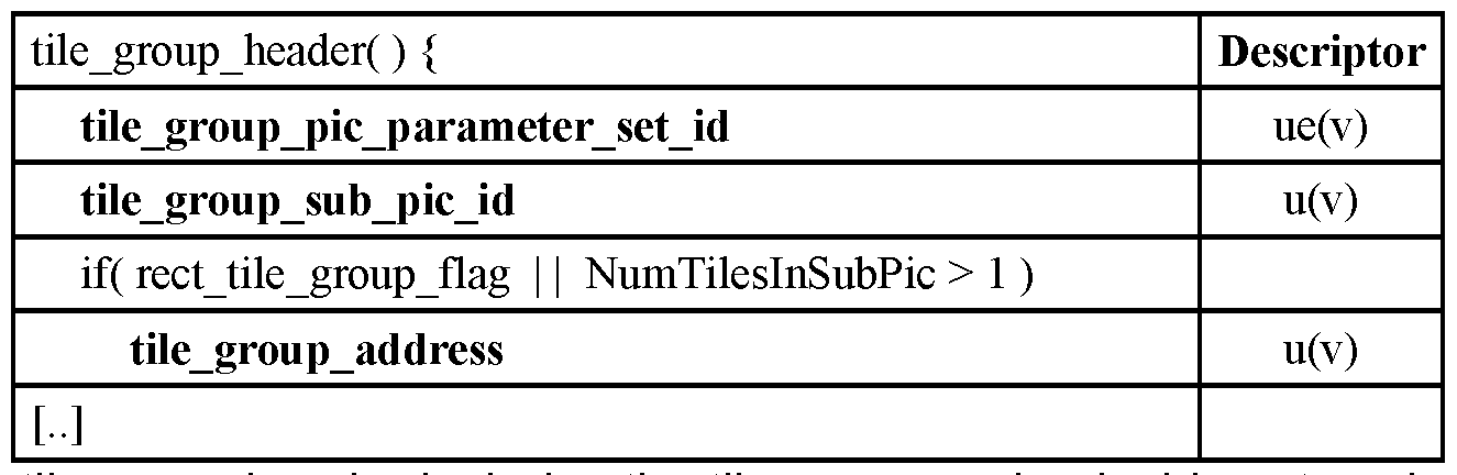
The tile group header includes the tile_group_sub_pic_id syntax element which specifies the identifier (i.e. , corresponding to one of the sub_pic_id[ i ] defined in the SPS) of the sub-pictures it belongs to. As a result, all the tile groups that share the same tile_group_sub_pic_id in the video sequence belong to the same sub-picture.
Figure 4 illustrates the process of generating a video bitstream composed of different regions of interest from one or several original bitstreams.
In a step 400, the regions to be extracted from the original bitstreams are selected. The regions may correspond for instance to a specific region of interest or a specific viewing direction in an omnidirectional content. The tile groups comprising encoded samples present in the selected set of regions are selected in the original bitstreams. At the end of this step, the identifier of each tile group in the original bitstreams, which will be merged in the resulting bitstreams, is determined. For example,
the identifiers of the tile groups 1 , 2, and 4 of picture 101 and of the tile group 3 of picture 100 in Figure 1 are determined.
In a step 401 , a new arrangement for the selected tile groups in the resulting video is determined. This consists in determining the size and location of each selected tile group in the resulting video. For instance, the new arrangement conforms to a predetermined ROI composition. Alternatively, a user defines a new arrangement.
In a step 402, the tile partitioning of the resulting video needs to be determined. When the tile partitioning of the original bitstreams are identical, the same tile partitioning is kept for the resulting video. At the end of this step, the number of rows and columns of the tile grid with the width and height of the tiles is determined and, advantageously stored in memory.
When determining the new arrangement, determined in step 401 , of the tile groups in the resulting video, the location of a tile group in the video may change regarding its location in the original video. In a step 403, the new locations of the tile groups are determined. In particular, the tile group partitioning of the resulting video is determined. The location of the tile groups are determined in reference with the new tile grid as determined in step 402.
In a step 404, new parameters sets are generated for the resulting bitstream. In particular, new PPS NAL units are generated. These new PPS contains syntax elements to encode the tile grid partitioning, the tile group partitioning and positioning and the association of the tile group identifier and the tile group index. To do so, the tile group identifier is extracted from each tile group and associated with the tile group index depending of the new decoding location of the tile group. It is reminded that each tile group, in the exemplary embodiment, is identified by an identifier in the tile group header and that each tile group identifier is associated with an index corresponding to the tile group index of the tile group in the picture in raster scan order. This association is stored in a PPS NAL unit. Assuming that there is no collision in the identifiers of the tile groups, when changing the position of a tile group in a picture, and thus changing the tile group index, there is no need to change the tile groups identifiers and thus to amend the tile group structure. Only PPS NAL units need to be amended.
In a step 405, the VCL NAL units, namely the tile groups, are extracted from the original bitstreams to be inserted in the resulting bitstream. It may happen that these VCL NAL units need to be amended. In particular, some parameters in the tile group header may not be compatible with the resulting bitstream and need to be amended. It would be
advantageous to avoid this amending step, as decoding, amending and recoding the tile group header is resource consuming.
In particular, APS NAL units may generate a need to amend tile group headers. It is reminded that APS stores the parameters needed for the adaptive loop filtering of the picture. Each APS comprises an identifier to identify this APS. Each tile group header comprises a flag that indicates if adaptive loop filtering is to be applied, and if this flag is true, the identifier of the APS containing the parameters to be used for adaptive loop filtering is stored in the tile header. In the current version of the standard, the APS identifier can take 32 values. Due to the low number of possible values, when merging tile groups from different bitstreams, there is a high risk of collision between these identifiers. Solving these collisions implies to change some APS identifiers and thus to amend the APS identifier in some tile group headers.
SUMMARY OF INVENTION
The present invention has been devised to address one or more of the foregoing concerns. It concerns an encoding and decoding method for a bitstream that allows solving APS identifier collision when merging tile groups from different bitstreams without amending the tile group encoded data. According to a first aspect of the invention, there is provided a method of encoding video data comprising pictures into a bitstream of logical units, pictures being divided into picture portions, picture portions being spatially divided into sub-portions, the method comprising:
- determining a parameter set applying to a sub-portion;
- determining a first identification information of the determined parameter set;
- determining a second identification information associated with the sub portion;
- encoding the sub-portion into a first logical unit comprising the first identification information;
- encoding the parameter set into a second logical unit comprising a parameter set identifier determined based on the first identification information and on the second identification information; and,
- encoding the association between the second identification information and the sub-portion and into a logical unit.
According to an embodiment, the association between the second identification information and the sub-portion is an association between the second identification information and the picture portion the sub-portion belongs to.
According to an embodiment:
- the second identification information is an extension identifier; and,
- the parameter set identifier comprises the first identification information and the extension identifier.
According to an embodiment:
- the second identification information is an offset; and,
- the parameter set identifier is the addition of the first identification information and of the offset.
According to an embodiment, the second identification information is an index of a parameter set.
According to an embodiment, the association between the second identification information and the sub-portion is encoded into a third logical unit.
According to an embodiment, the second and third logical units are parameter set logical units applying at different levels of the bitstream.
According to an embodiment, the association between the second identification information and the sub-portion is encoded into the second logical unit.
According to an embodiment, a plurality of parameter sets are determined, the method further comprising:
- encoding the plurality of parameter sets into the second logical unit, each parameter set being associated with an index, the second logical unit comprising for each picture portion, the association of an index of the picture portions and the index of a parameter set.
According to an embodiment, the parameter set is a filter parameter set.
According to an embodiment, the parameter set is a picture parameter set.
According to another aspect of the invention, there is provided a method for decoding a bitstream of logical units of video data comprising pictures, pictures being divided into picture portions, picture portions being spatially divided into sub-portions, the method comprising:
- parsing a first logical unit comprising a sub-portion to determine a first identification information of a parameter set applying to the sub-portion;
- parsing a second logical unit comprising the association between a second identification information and the sub-portion;
- determining a parameter set identifier based on the first identification information and the second identification information;
- decoding a logical unit comprising the parameter set identified by the parameter set identifier;
- decoding the sub-portion comprised in the first logical unit using the decoded parameter set.
According to an embodiment, the association between the second identification information and the sub-portion is an association between the second identification information and the picture portion the sub-portion belongs to.
According to an embodiment:
- the second identification information is an extension identifier; and,
- the parameter set identifier comprises the first identification information and the extension identifier.
According to an embodiment:
- the second identification information is an offset; and,
- the parameter set identifier is the addition of the first identification information and the offset.
According to an embodiment, the second identification information is an index of a parameter set.
According to an embodiment, the logical unit comprising the parameter set is a third logical unit.
According to an embodiment, the second and third logical units are parameter set logical units applying at different levels of the bitstream.
According to an embodiment, the logical unit comprising the parameter set is the second logical unit.
According to an embodiment, a plurality of parameter sets are determined, the method further comprising:
- decoding the plurality of parameter sets from the second logical unit, each parameter set being associated with an index, the second logical unit comprising for each sub-portion, the association of an index of the sub portion and the index of a parameter set.
According to an embodiment, the parameter set is a filter parameter set.
According to an embodiment, the parameter set is a picture parameter set. According to another aspect of the invention, there is provided a method for merging sub-portions from a plurality of original bitstreams of video data into a resulting
bitstream, bitstreams being composed of logical units comprising pictures, pictures being divided into picture portions, picture portions being spatially divided into sub-portions, the method comprising:
- parsing the logical units comprising the sub-portions to determine a first identification information of a parameter set associated with each sub portion;
- extracting logical units comprising a parameter set applying to a sub portion, the logical unit being identified by the first identification information;
- encoding a logical unit comprising the association of a second identification information with a sub-portion for each sub-portion;
- encoding each extracted logical unit comprising a parameter set into a logical unit comprising the parameter set and a parameter set identifier determined based on the first identification information and the second identification information;
- generating the resulting bitstream comprising the logical units comprising the sub-portions, the encoded logical unit comprising the association of a second identification information with the sub-portions and the encoded logical units comprising the parameter sets.
According to an embodiment, the association between the second identification information and the sub-portion is an association between the second identification information and the picture portion the sub-portion belongs to.
According to an embodiment:
- the second identification information is an extension identifier; and - the parameter set identifier comprises the first identification information and the extension identifier.
According to an embodiment:
- the second identification information is an offset; and
- the parameter set identifier is the addition of the first identification information and of the offset.
According to an embodiment, the second identification information is an index of a parameter set.
According to an embodiment, the parameter set is a filter parameter set.
According to an embodiment, the parameter set is a picture parameter set.
According to another aspect of the invention, there is provided a method of generating a file comprising a bitstream of logical units of encoded video data comprising pictures, pictures being divided into picture portions, picture portions being spatially divided into sub-portions, the method comprising:
- encoding the bitstream according to the invention;
- generating a first track comprising the logical units containing the parameter sets, and the logical unit containing the association between the second identification information and the sub-portions;
- generating for a sub-portion, a track containing the logical unit containing the sub-portion; and,
- generating the file comprising the generated tracks.
According to another aspect of the invention, there is provided a bitstream of logical units, the bitstream comprising encoded video data comprising pictures, pictures being divided into picture portions, picture portions being spatially divided into sub- portions, the bitstream comprising:
- a first logical unit comprising a sub-portion;
- a second logical unit comprising a parameter set applying to the sub portion and a parameter set identifier determined based on a first identification information of the parameter set and on a second identification information associated with the sub-portion; and,
- a logical unit comprising the association between the second identification information and the sub-portion.
According to another aspect of the invention, there is provided a computer program product for a programmable apparatus, the computer program product comprising a sequence of instructions for implementing a method according to the invention, when loaded into and executed by the programmable apparatus.
According to another aspect of the invention, there is provided a computer- readable storage medium storing instructions of a computer program for implementing a method according to the invention.
According to another aspect of the invention, there is provided a computer program which upon execution causes the methods of the invention to be performed.
At least parts of the methods according to the invention may be computer implemented. Accordingly, the present invention may take the form of an entirely hardware embodiment, an entirely software embodiment (including firmware, resident
software, microcode, etc.) or an embodiment combining software and hardware aspects that may all generally be referred to herein as a "circuit", "module" or "system". Furthermore, the present invention may take the form of a computer program product embodied in any tangible medium of expression having computer usable program code embodied in the medium.
Since the present invention can be implemented in software, the present invention can be embodied as computer-readable code for provision to a programmable apparatus on any suitable carrier medium. A tangible, non-transitory carrier medium may comprise a storage medium such as a floppy disk, a CD-ROM, a hard disk drive, a magnetic tape device or a solid-state memory device and the like. A transient carrier medium may include a signal such as an electrical signal, an electronic signal, an optical signal, an acoustic signal, a magnetic signal or an electromagnetic signal, e.g., a microwave or RF signal.
BRIEF DESCRIPTION OF DRAWINGS
Embodiments of the invention will now be described, by way of example only, and with reference to the following drawings in which:
Figures 1a and 1 b illustrate two different application examples for the combination of regions of interest;
Figure 2a and 2b illustrate some partitioning in encoding systems;
Figure 3 illustrates the organisation of the bitstream in the exemplary coding system VVC;
Figure 4 illustrates an example of the process of generating a video bitstream composed of different regions of interest from one or several original bitstreams;
Figure 5 illustrates issues with APS NAL unit when merging tile groups from different bitstreams;
Figure 6 illustrates the encoding of an APS extension identifier according to an embodiment of the invention;
Figure 7 illustrates another embodiment where the second identification information is implemented as an offset to be applied to the APS identifier;
Figure 8 illustrates an embodiment where the APS associated with different tile groups are merged;
Figure 9 illustrates an embodiment where a plurality of APS can be associated with a tile group;
Figure 10 illustrates the main steps of an encoding process according to an embodiment of the invention;
Figure 11 illustrates the main steps of a decoding process according to an embodiment of the invention;
Figure 12 illustrates the extraction and merge operation of two bitstreams stored in a file to form a resulting bitstream stored in a resulting file in an embodiment of the invention;
Figure 13 illustrates the main step of the extraction and merge process at file format level in an embodiment of the invention;
Figure 14 the encoding of an APS extension identifier according to an embodiment of the invention;
Figure 15 is a schematic block diagram of a computing device for implementation of one or more embodiments of the invention. DETAILED DESCRIPTION OF THE INVENTION
Figure 5 illustrates issues with APS NAL unit when merging tile groups from different bitstreams.
Adaptive loop filtering (ALF) may be used as an in-loop filter for each picture. ALF requires the transmission of a set of parameters named ALF parameters. The ALF parameters are typically transmitted in a dedicated parameter set called APS for ALF Parameter Set. The APS is transmitted as a non-VCL NAL unit. It contains an identifier of the APS and the ALF parameters to be used in one or several tile groups of one or several pictures. The identifier is a value comprised in the range 0-31. The update mechanism is the following: when a new APS is received with a same identifier as a previous one, it replaces the previous one. The APS can change very rapidly, for each picture, the ALF parameters may be recomputed and new APS may be generated either as replacement or in addition to previous ones. The APS may typically take the following syntax:

A tile group header comprises a flag, typically called tile_group_alf_enabled_flag, to indicate if the ALF filter is used. When ALF filter is used, the tile group header
comprises the identifier of the APS to be used. In each successive picture, a tile group with the same index is likely to change its APS identifier. These syntax elements of the tile group header are typically encoded according to the following syntax:


ALF and one for the LMCS or Reshaper filter or also scaling list data. For example, the identifier for the ALF filter is named tile_group_alf_aps_id and tile_group_lmcs_aps_id. All the embodiments described below apply the same way to all the APS identifiers described in the tile group header.
When merging different tile groups from different bitstreams, this design generates a possibility of collision between the APS identifiers. Figure 5 illustrates an example of such collision. In Figure 5, the tile group 3 of a first bitstream 500 refers to an APS 510 having an identifier with the value 0 in bitstream 500. The tile group 4 in a
second bitstream 501 also refers to an APS 511 having an identifier having the value 0 in bitstream 501. APS 510 and APS 511 , while having the same identifier“0”, are likely to contain different ALF parameters as they are defined in different bitstreams.
When generating the resulting bitstream 502, it is necessary to modify the identifier of at least one of the APS 520 and 521 in order to provide each tile group with the right ALF parameters. In the example, APS 521 corresponds to APS 511 with an amended identifier now taking the value“1”. To do so, it is necessary to read, decode, amend and re-encode the APS 521 with the new identifier. This is not a too complex operation as APS are relatively small NAL units with mainly fixed variable length elements. It is also necessary to change the APS identifier referenced in the tile header group of the tile group 4 to correctly reference the APS 521 with its new identifier. This is a much more complex operation as the tile header is a complex structure with a lot of variable length elements. This means that the complete header needs to be decoded, amended and re-encoded, especially since the APS identifier is encoded in the last part of the tile group header.
In order to improve the merging operation, it may be contemplated to amend the structure of the tile group header. For example, the APS identifier may be encoded at the beginning of the tile group header using a fixed length syntax element. By doing so, the rewriting of the tile group header would only need to decode this first syntax element, to amend it and then to copy the rest of the tile group header. However, this copy would still be a costly operation due to the size of the tile group header and the tile group payload.
It may also be contemplated to increase the range of possible values for the APS identifier. The length of the APS identifier field could be indicated in the PPS. With this improvement, it would be possible for several communicating encoders to use different sub ranges of APS identifiers for encoding bitstreams in order to allow the merge of tile groups from these bitstreams with no collision in APS identifiers. However, this solution has some drawbacks. It increases the number of bits needed for the encoding of the APS identifier that is present in each tile group, so typically several times per picture. This implies a decrease of the compression ratio, which is not desirable. Moreover, it may not be possible to know at encoding time all the merging operation that will be necessary in order to manage the sub ranges of APS identifiers in order to plan all the merging operations. It may also be contemplated to generate randomly the APS identifiers in order to decrease the risk of collision. However, due to the high number of
APS needed to encode a typical bitstream, it is unlikely to solve entirely the collision problem.
According to an embodiment of the invention, the APS identifier that is based on the original bitstream from which the APS and associated tile groups are issued forms a first identification information. It is completed with a second identification information. In this embodiment, each APS comprises the APS identifier and this second identification information, each tile group comprises only the APS identifier while the PPS, or another parameter set, comprises for each tile group, the second identification information.
According to this embodiment, the merge operation comprises the insertion of the second identification information in each APS based on the original bitstream it comes from and the insertion in the PPS of the second identification information associated with each tile group. The tile group NAL unit is not modified, and the tile group header keeps its APS identifier.
At decoding, when decoding a tile group, the decoder needs to identify the right APS corresponding to the tile group. This is done by obtaining the APS identifier from the tile group header. Then the second identification information associated with this tile group is obtained from the PPS. The right APS is then identified by both the APS identifier and the second identification information. It must be noted that collisions are solved as, even in case of APS identifier collision, as both APS come from two different original bitstreams, the associated second identification information is different, meaning that the identification based on both the APS identifier and the second identification information correctly identify the right APS. This solution does not imply the rewriting of the tile group header, thus simplifying the merging operation.
In a first example of this embodiment, the second identification information is implemented as an APS extension identifier. The syntax of the APS can be, for example

The presence of the APS extension identifier in the APS is signalled using a flag, for example named aps_id_extension_flag, encoded on one bit. The APS extension identifier, for example called aps_extension_id, is encoded on a fixed length for example
5 bits. In a variant, the encoding length in bits is signalled in one of the Parameters Set NAL unit. For instance, the SPS or the PPS. In the table above, the coding method (descriptor column) is u(v) for aps_extension_id. In yet another variant, when aps_id_extension_flag equals 1 , the aps_extension_id flag is preceded by an aps_extension_length syntax element that specifies the length in bits of aps_extension_id. In another variant, Exp-Golomb coding is used and the new syntax element (aps_extension_id) is encoded for instance using ue(v) coding method.
For example, the semantics of syntax elements are the following:
- adaptation_parameter_set_id provides an identifier for the APS for reference by other syntax elements. The value of adaptation_parameter_set_id shall be in the range of 0 to 31.
- aps_id_extension_flag equal to 1 specifies the presence of aps_extension_id in the APS. aps_extension_flag equal to 0 specifies the absence of the aps_extension_id.
- aps_extension_id when present, provides extended identifier for reference by other syntax elements. The value of aps_extension_id shall be in the range of 0 to 31. When not present the value of aps_extension_id is inferred to be equal 0.
At decoding, the replacement rule of APS becomes that a new APS replaces a previous one if it has the same APS identifier and the same APS extension identifier.
The PPS contains an association for each tile group of the associated APS extension identifier, according, for example, to the following syntax:

For example, the semantics of syntax elements are the following:
- signalled_aps_id_extension_flag equal to 1 specifies the presence of tile_group_aps_extension_id[ i ] in the PPS. signalled_aps_id_extension_flag equal to 0 specifies the absence of the tile_group_aps_extension_id[ i ] in the PPS.
- tile_group_aps_extension_id[ i ] specifies the tile group extension ID of the i-th tile group, when present. When not present, the tile_group_aps_extension_id[ i ] is inferred equal to 0, for each i in the range of 0 to num_tile_group_in_pic_minus1 inclusive. In a variant, the length of the APS extension identifier field decreased by one is first encoded using variable length encoding before the table for example according to the following syntax:

For example, the semantics of syntax elements are the following:
- signalled_aps_id_extension_flag equal to 1 specifies the presence of signalled_aps_id_extension_length_minus1 and tile_group_aps_extension_id[ i ] in the PPS. signalled_aps_id_extension_flag equal to 0 specifies the absence
of the signalled_aps_id_extension_length_minus1 and tile_group_aps_extension_id[ i ] in the PPS.
- signalled_aps_id_extension_length_minus1 when present, specifies the number of bits used to represent the syntax element tile_group_extension_id and aps_extension_id of the PPS. The value of signalled_aps_id_extension_length_minus1 shall be in the range of 0 to 15, inclusive. When not present the value of signalled_aps_id_extension_length_minus1 is inferred to be equal to Ceil( Log2( num_tile_groups_in_pic_minus1 + 1 ) ) - 1.
- tile_group_aps_extension_id[ i ] specifies the tile group extension ID of the i-th tile group, when present. When not present, the tile_group_aps_extension_id[ i ] is inferred equal to 0, for each i in the range of 0 to num_tile_group_in_pic_minus1 inclusive. A variable length encoding of the extension identifier may have been used. This would have been more compact but more complex to parse.
No modification of the tile group header is contemplated. The presence of the APS identifier when combined with the APS extension identifier obtained from the PPS allows determining the right APS in all configurations.

The semantics of some syntax elements of the tile group header is the following: tile_group_aps_id specifies the identifier of the APS in use.
The variable tileGroupExtensionldx which specifies the index of the tile group APS extension identifier is derived as follows:
if( rect_tile_group_flag ) {
tileGroupExtensionldx = 0
while( tile_group_address !=
tile_group_id[ tileGroupExtensionldx] )
tileGroupExtensionldx ++
}
else {
tileGroupExtensionldx = 0;
}
The APS in use is the APS NAL unit having adaptation_parameter_set_id equal to tile_group_aps_id and the aps_extension_id equal to tile_group_aps_extension_id[tileGroupExtensionldx]
The Temporalld, an identifier indicative of the temporal level, of the APS NAL unit having adaptation_parameter_set_id equal to tile_group_aps_id and the aps_extension_id equal to tile_group_aps_extension_id[tileGroupExtensionldx] shall be less than or equal to the Temporalld of the coded tile group NAL unit.
When multiple APSs with the same value of adaptation_parameter_set_id and aps_extension_id are referred to by two or more tile groups of the same picture, the multiple APSs with the same value of adaptation_parameter_set_id and aps_extension_id shall have the same content.
Figure 6 illustrates this embodiment. Original bitstreams 600 and 601 with respective tile groups 3 and 4 to be merged, each referring to an APS, respectively 610 and 611 , having both an APS identifier with a value 0, are identical to those of Figure 5.
In the resulting bitstream 602, both tile groups 3 and 4 are unmodified and continue to refer to the associated APS using the APS identifier with a value of 0. What changed is that now, the APS originated from bitstream 600 and corresponding to APS 610 comprises both an APS identifier with a value 0 and an APS extension identifier with a value of 0. The APS 621 corresponding to APS 611 from bitstream 601 comprises an APS identifier with a value 0 and an APS extension identifier with a value 1. The PPS comprises a table 630 that associates the tile group 3 with the APS extension identifier 0 and the tile group 4 with the APS extension identifier 1. At decoding, the decoder is therefore able to decode the tile group 3 with the correct identification of the associated APS 620 based on the APS identifier stored in the tile group 3 and the associated APS extension identifier form the PPS. The same is true for the decoding of the tile group 4.
It is to be noted that this mechanism works even if the APS identifier changes from a picture to another for the tile groups with the same identifier. The APS extension identifier will stay the same, still allowing the identification of the right APS.
This proposed embodiment allows solving the APS identifier collisions while keeping the tile group structure intact. Accordingly, the merge process of tile group from different original bitstreams is simplified.
In a variant of this embodiment, the APS extension identifier is called an APS group identifier. The semantics are the same except the naming of syntax element for which extension is replaced with group. In another variant extension is replaced with extended.
In order to simplify the parsing of the PPS, the different loops could be merged as illustrated by the following syntax when the fixed length encoding length equal 5 is used:

In a variant the signalled_aps_group_id_length_minus1 specifies the length of the identifier extension code, the syntax of the PPS is illustrated by the following syntax:


Figure 7 illustrates another variant of this embodiment where the second identification information is implemented as an offset to be applied to the APS identifier.
According to this embodiment, the APS contains an identifier field that is named adaptation_parameter_set_id. It corresponds to the original APS identifier as defined in the original bitstream the APS comes from.

For example, the semantics of syntax elements are the following:
- adaptation_parameter_set_id provides an identifier for the APS for reference by other syntax elements. The value of adaptation_parameter_set_id shall be in the range of 0 to 31.
The PPS associates each tile group with a signed offset that is computed to avoid APS identifier collision in the merged bitstream. This offset corresponds to the aps_offset syntax element described in the table below.
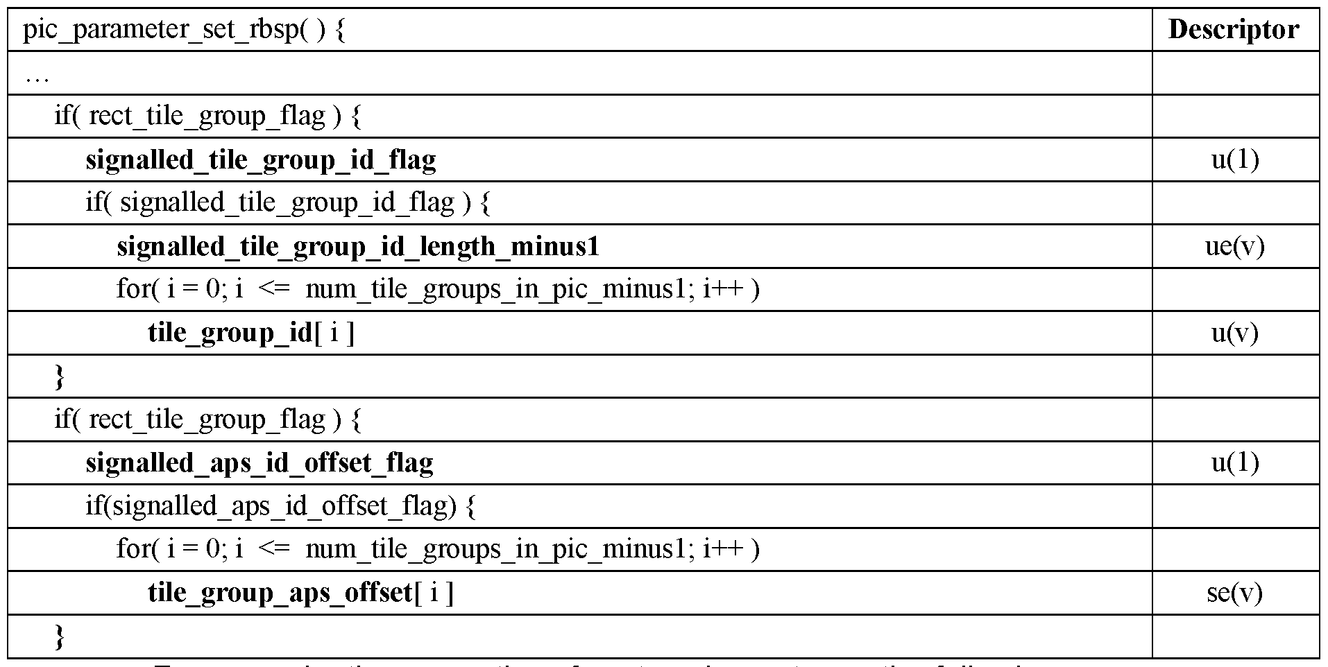
For example, the semantics of syntax elements are the following:
- signalled_aps_id_offset_flag equal to 1 specifies the presence of tile_group_aps_offset_id [ i ] in the PPS. signalled_aps_id_offset_flag equal to 0 specifies the absence of the tile_group_aps_offset_id[ i ] in the PPS.
- tile_group_aps_offset_id[ i ] specifies the tile group ID offset of the i-th tile group, when present. tile_group_aps_offset_id should be in range of -32 to 32. When not present, the tile_group_aps_offset_id[ i ] is inferred equal to i, for each i in the range of 0 to num_tile_group_in_pic_minus1 inclusive.
The tile group header is left unchanged indicating the APS identifier associated with the tile group.
At decoding, the decoder identifies the APS for a tile group by adding the offset obtained from the PPS to the APS identifier obtained from the tile group header to obtain the actual APS identifier comprised in the APS.
The semantics of some syntax elements of the tile group header is the following: tile_group_aps_id specifies the identifier of the APS in use.
The variable tileGroupOffsetldx which specifies the index of the tile group APS offset identifier is derived as follows:
if( rect_tile_group_flag ) {
tileGroupOffsetldx = 0
while( tile_group_address != tile_group_id[ tileGroupOffsetldx] ) tileGroupOffsetldx ++
}
else {
tileGroupOffsetldx = 0;
}
The APS in use is the APS NAL unit having adaptation_parameter_set_id equal to tile_group_aps_id + tile_group_aps_offset_id[tileGroupOffsetldx]
The Temporalld of the APS NAL unit having adaptation_parameter_set_id equal to tile_group_aps_ id + tile_group_aps_offset_id[tileGroupOffsetldx] shall be less than or equal to the Temporalld of the coded tile group NAL unit.
When multiple APSs with the same value of adaptation_parameter_set_id are referred to by two or more tile groups of the same picture, the multiple APSs with the same value of adaptation_parameter_set_id shall have the same content.
Figure 7 illustrates this embodiment. Original bitstreams 700 and 701 with respective tile groups 3 and 4 to be merged, each referring to an APS, respectively 710 and 711 , having both an APS identifier with a value 0, are identical to those of Figure 5.
In the resulting bitstream 702, both tile groups 3 and 4 are unmodified and continue to refer to the associated APS using the APS identifier with a value of 0. What changed is that now, the APS originated from bitstream 700 and corresponding to APS 710 comprises an APS identifier with a value 0 corresponding to the original APS identifier of 0 added to the offset 0. The APS 721 corresponding to APS 711 from bitstream 701 comprises an APS identifier with a value 3 corresponding to the original APS identifier of 0 added to the offset of 3. The PPS comprises a table 730 that associates the tile group 3 with the offset 0 and the tile group 4 with the offset 3. At decoding, the decoder is therefore able to decode the tile group 3 with the correct identification of the associated APS 720 based on the APS identifier stored in the tile group 3 added to the offset from the PPS. The same is true for the decoding of the tile group 4.
In a variant, the PPS provides an additional field called tile_group_aps_base_id, which is an integer that will be added to the APS identifier to obtain the actual identifier. The goal is to keep the APS identifier stored in the APS structure and the offsets stored in the PPS association table smaller to save on the encoding. The PPS syntax according to this variant may be:

For example, the semantics of syntax elements are the following:
- signalled_aps_id_offset_flag equal to 1 specifies the presence of tile_group_aps_id_base and tile_group_aps_offset_id[ i ] in the PPS. signalled_aps_id_offset_flag equal to 0 specifies the absence of the tile_group_aps_id_base and tile_group_aps_offset_id[ i ] in the PPS. - tile_group_aps_id_base is the base value of all the tile group APS identifiers. The range of tile_group_aps_id_base shall be in range of 0 to 31 , inclusive.
- tile_group_aps_offset_id[ i ] specifies the tile group ID offset of the i-th tile group, when present. tile_group_aps_offset_id should be in range of -32 to 32. . When not present, the tile_group_aps_offset_id[ i ] is inferred equal to i, for each i in the range of 0 to num_tile_group_in_pic_minus1 inclusive.
According to this embodiment, the APS contains an identifier field that is named adaptation_parameter_set_id_minus_base that is a signed integer. It corresponds to the original APS identifier as defined in the original bitstream the APS comes from at which the aps_id_base has been removed. The descriptor encoding se(v) corresponds to a variable length encoding of a signed integer.

For example, the semantics of syntax elements are the following:
adaptation_parameter_set_id_minus_base provides an identifier for the APS for reference by other syntax elements. The value of adaptation_parameter_set_id_minus_base shall be in the range of -15 to +14, inclusive. The semantics of some syntax elements of the tile group header is the following: tile_group_aps_id specifies the identifier of the APS in use.
The variable tileGroupOffsetldx which specifies the index of the tile group APS offset identifier is derived as follows:
if( rect_tile_group_flag ) {
tileGroupOffsetldx = 0
while( tile_group_address != tile_group_id[ tileGroupOffsetldx ] ) tileGroupOffsetldx ++
}
else {
tileGroupOffsetldx = 0;
}
The APS in use is the APS NAL unit having
adaptation_parameter_set_id_minus_base + tile_group_aps_id_base equal to tile_group_aps_id_base + tile_group_aps_id +
tile_group_aps_offset_id[tileGroupOffsetldx]
The Temporalld of the APS NAL unit having
adaptation_parameter_set_id_minus_base + tile_group_aps_id_base equal to tile_group_aps_id_base + tile_group_aps_id +
tile_group_aps_offset_id[tileGroupOffsetldx] shall be less than or equal to the
Temporalld of the coded tile group NAL unit.
When multiple APSs with the same value of adaptation_parameter_set_id_minus_base are referred to by two or more tile groups of the same picture, the multiple APSs with the same value of adaptation_parameter_set_id_minus_base id shall have the same content.
According to another embodiment, the APS NAL unit syntax is modified in order to allow the APS to store several ALF parameter sets. The idea is to merge the APS from different bitstreams having the same APS identifier into a single APS in the resulting bitstream having the same identifier and storing the sets of ALF parameters that were included into the original APS. An additional table is included in the resulting APS to indicate for each tile group referring this APS identifier, which set of ALF parameters must be used.
The syntax of the new APS may be as follows:


For example, the semantics of syntax elements are the following:
• extended_aps_flag equal to 1 specifies the presence of aps_num_tile_group_signaled_minus1 , aps_tile_group_address[ i ] and aps_tile_group_alf_idx[ i ]. extended_aps_flag equal to 0 specifies the absence of aps_num_tile_group_signaled_minus1 , aps_tile_group_address[ i ] and aps_tile_group_alf_idx[ i ].
• aps_num_tile_group_signaled_minus1 plus 1 specifies the number of aps_tile_group_address[ i ] and aps_tile_group_alf_idx[ i ] specified in the APS; aps_num_tile_group_signaled_minus1 shall be in the range of 0 to num_tile_group_in_pic_minus1 , inclusive.
• aps_tile_group_address[i] specifies the tile group address of each tile group signalled in the APS.
• In a variant, aps_tile_group_address[i] specifies the tile group index of each tile group signalled in the APS. The range of aps_tile_group_address[i] shall be in range of 0 to num_tile_group_in_pic_minus1 , inclusive.
• aps_tile_group_alf_idx[i] specifies the index of the set of ALF parameters in the APS to be used for the tile group with a tile_group_address equal to aps_tile_group_address[ i ]. aps_tile_group_alf_idx[ i ] shall be in range of 0 to aps_num_alf_data_minus1 , inclusive.
• In a variant, aps_tile_group_alf_idx[i] specifies the index of the set of ALF parameters in the APS to be used for the tile group with a tile group index equal to aps_tile_group_address[ i ]. aps_tile_group_alf_idx[ i ] shall be in range of 0 to aps_num_alf_data_minus1 , inclusive
• aps_num_alf_data_minus1 specifies the number of ALF parameter sets specified in the APS.
The semantics of some syntax elements of the tile group header is the following:
The Temporalld of the APS NAL unit having
adaptation_parameter_set_id_minus_base + tile_group_aps_id_base equal to tile_group_aps_id_base + tile_group_aps_id +
tile_group_aps_offset_id[tileGroupOffsetldx] shall be less than or equal to the
Temporalld of the coded tile group NAL unit.
When multiple APSs with the same value of adaptation_parameter_set_id_minus_base are referred to by two or more tile groups of the same picture, the multiple APSs with the same value of adaptation_parameter_set_id_minus_base id shall have the same content.
Figure 8 illustrates this embodiment. A first bitstream 800 comprises a tile group
3 referring an APS 810 containing a set of ALF parameters called ALF data 1. A second bitstream 801 comprises a tile group 4 referring an APS 811 containing a set of ALF parameters called ALF data 2. Both APS in the two bitstreams have the same APS identifier with a value 0. The resulting bitstream 802 comprises both tile groups 3 and 4. These tile groups still refer to an APS with an APS identifier with a value 0. This APS 820 with an APS identifier with a value 0 comprises two ALF parameter sets, namely ALF data 1 and ALF data 2, indexed respectively 0 and 1. The APS also comprises a table that associates the tile group 3 with the index 0 of the ALF parameter set ALF data 1. The tile group 4 is associated with the index 1 of the ALF parameters set ALF data 2.
Accordingly, the decoder is able to retrieve the APS from the APS identifier stored in the tile group header and then to identify in the APS the ALF parameter set to be used for filtering based on the tile group identifier. The merge process does not need to rewrite the tile group NAL units or the PPS. All the mechanism implies only the APS. Figure 9 illustrates an embodiment where a plurality of APS can be associated with a tile group. This may allow applying different ALF parameter sets to different coding units within the tile group. A first bitstream 900 comprises a tile group 3 referring three different APS 910 with respective APS ids 0, 1 , and 2. A second bitstream 901 comprises a tile group 4 referring three different APS 911 with respective APS ids 0, 2, and 3.
When generating a resulting bitstream 902 comprising tile group 3, and 4, APS identifiers collisions may occur as it was the case with a single APS referred in a tile group. The previous embodiments described above to solve the APS identifier collisions may be applied successively to the plurality of APS referred in the tile groups. For instance, an APS extension identifier may be used.
In a first embodiment of a tile group referring to a plurality of APS, assuming a fixed number of APS is provided, the syntax of the tile group header may be as follows:

In a second embodiment of a tile group referring to a plurality of APS, assuming a variable number of APS is provided, the syntax of the tile group header may be as follows:

Figure 10 illustrates the main steps of an encoding process according to an embodiment of the invention.
The described encoding process concerns the encoding according to an embodiment of the invention of a single bitstream. The obtained encoded bitstream may
be used in a merging operation as described above as an original bitstream or as the resulting bitstream.
In a step 1000, a tile portioning of the pictures is determined. For instance, the encoder defines the number of columns and rows so that each region of interest of the video is covered by at least one tile. In another example, the encoder is encoding an omnidirectional video where each tile corresponds to a predetermined field of view in the video. The tile partitioning of the picture according to a tile grid is typically represented in a parameter set NAL unit, for example a PPS according to the syntax presented in reference to Figure 3.
In a step 1001 , a set of tile groups are defined, each tile group comprising one or more tiles. In a particular embodiment, a tile group is defined for each tile of the picture. Advantageously, in order to avoid some VCL NAL unit rewriting in merge operation, a tile group identifier is defined for each tile group in the bitstream. The tile group identifiers are determined in order to be unique for the tile group. The unicity of the tile group identifiers may be defined at the level of a set of bitstreams comprising the bitstream currently encoded.
The number of bits used to encode the tile group identifier, corresponding to the length of the tile group identifier, is determined as a function of the number of tile groups in the encoded bitstream or as a function of a number of tile groups in a set of different bitstreams comprising the bitstream being currently encoded.
The length of the tile group identifier and the association of each tile group with an identifier is specifically specified in parameter set NAL unit as the PPS.
In a step 1002, each tile group is associated to decoding context parameters and in particular to an APS when adaptive loop filtering is to be applied. The association comprises the insertion in the tile group header of an APS identifier. Then, the PPS is generated comprising for each tile group a second identification information. The APS is generated with an APS identifier based on both the APS identifier inserted in the tile group header and the second identification information associated with the tile group in the PPS. The second identification information may be an APS extension identifier or an offset to be added to the APS identifier.
In a variant, the APS is defined with a plurality of ALF parameter sets, an association table being inserted to associate a tile group with an index of an ALF parameter set within the APS. The second identification information is the index of the ALF data associated with the tile group.
In a step 1003, the samples of each tile group are encoded according to the parameters defined in the different parameter sets. In particular, the encoding will be based on the ALF parameters in the APS associated with the tile group. A complete bitstream is generated comprising both the non-VCL NAL units corresponding to the different parameter sets and the VCL NAL units corresponding to the encoded data of the different tile groups.
In an embodiment, the encoding process defines sub-picture partitioning. When pictures are divided into sub-pictures, merging of parts of pictures from different video sequences are based on sub-pictures and not individual tile groups in these sub-pictures. Thus, a second identification information is defined at the level of the sub-picture and will apply to all the tile groups in this sub-picture. In such a case, the step 1000 includes a preliminary step of determination of sub-picture partitioning. Typically, the sub-picture location and size are made to cover a specific region of interests. Following this preliminary step, each sub-picture may be further divided into tiles as described previously in step 1001 applying to the sub-picture instead of the picture. In step 1002, the association comprises the insertion in the tile group header of an APS identifier. In a variant, several APS identifiers are inserted, one for each loop filter. Then, the SPS is generated comprising for each sub-picture a second identification information. The APS is generated with an APS identifier based on both the APS identifier inserted in the tile group header and the second identification information associated with the Sub-picture of the tile group in the SPS. The second identification information may be an APS extension identifier or an offset to be added to the APS identifier.
Figure 11 illustrates the main steps of a decoding process according to an embodiment of the invention.
In a step 1100, the decoder parses the bitstream in order to determine the tile portioning of the picture, or of each sub-picture of the picture when present. This information is obtained from a parameter set, typically from the PPS NAL unit. The syntax elements of the PPS are parsed and decoded to determine the grid of tiles.
In a step 1101 , the decoder determines the tile group partitioning of the picture and in particular obtain the number of tile groups associated with an identification information of each tile group. This information is valid for at least one picture, but stay valid generally for many pictures. It may take the form of the tile group identifier that may be obtained from a parameter set as the PPS NAL unit as described in Figures 6, 7, 8, and 9.
In a variant, in a step 1101 the decoder determines the number of tile groups associated with an identification information of each sub-picture when present.
In a step 1102, the decoder parses the bitstream to determine the APS identifier that is associated with each tile group. This is typically done by extracting an APS identification information from the tile group header and by combining this information with a second identification information associated with the tile group in a parameter set, typically in a PPS or SPS for example when sub-pictures are present. Based on both the APS identification information and the second identification information, an actual APS identifier is determined that allows the determination of an APS NAL unit associated with the tile group.
In an alternate embodiment, the decoder parses the tile group header to determine an APS identifier associated with the tile group. Then, the decoder parses the APS NAL unit to determine an ALF parameter set in the APS that is associated with the tile group identifier.
In a step 1103, the decoder decodes the VCL NAL units corresponding to the tile groups according to the parameters determined in the previous steps. In particular, the decoding may include an adaptive loop filtering step with parameters obtained from the APS identified in the previous steps as being associated with the tile group.
Figure 12 illustrates the merge operation of two bitstreams stored in a file to form a resulting bitstream stored in a resulting file in an embodiment of the invention.
Figure 13 illustrates the main step of the merge process at file format level in an embodiment of the invention.
Figure 12 illustrates the merge of two ISO BMFF files 1200 and 1201 resulting in a new ISO BMFF file 1202 according to the method of Figure 13.
The encapsulation of the VVC streams consists in this embodiment in defining one tile track for each tile group of the stream and one tile base track for the NAL units common to the tile groups. It could also be possible to group more than one tile group for example as a sub-picture in one tile track. For example, the file 1200 contains two tile groups one with the identifier Ί .1’ and another one with identifier Ί .2’. The samples corresponding to each tile group Ί . T and Ί .2’ are described respectively in one tile track similarly to tile tracks in ISO/IEC 14496-15. While initially designed for HEVC, the VVC tile groups could be encapsulated in tile tracks. This VVC tile track could be differentiated from HEVC tile track by defining a new sample entry for instance‘vvtT instead of‘hvtT. Similarly, a tile base track for HEVC is extended to support VVC format. This VVC tile base track could be differentiated from HEVC tile base track by defining a different
sample entry. The VVC tile base track describes NAL units common to the two tile groups. Typically, it contains mainly non-VCL NAL unit such as the Parameter Sets and the SEI NAL units. For example, it can be one of the Parameters Sets NAL units.
First, the merging method consists in determining in step 1300 the set of tile tracks from the two streams to be merged in a single bitstream. For instance, it corresponds to the tile tracks of the tile group with the identifier‘2.T of 1201 file and of the tile group with identifier Ί .2’ of the file 1200.
Then the method in a step 1301 determines the new decoding locations of the tile groups and generates new Parameter Sets NAL units (i.e. , SPS or PPS and APS) to describe these new decoding locations in the resulting stream accordingly to the embodiments described above. Since all the modifications consist in modifying only the non-VCL NAL units, it is equivalent to generating in a step 1302 a new Tile Base Track. The samples of the original tile tracks corresponding to the extracted tile groups remain identical. The‘tile tracks of the file 1202 reference the tile base tracks with a track reference type set to‘tbas’. The tile base track references as well the tile tracks with a track reference type set to‘sbat’.
The advantage of this method is that combining two streams consists mainly in generating a new tile base track and update the track reference boxes and copying as is the tile tracks samples corresponding to the selected tile groups. The processing is simplified since rewriting process of the tile tracks samples is avoided compared to prior art.
According to an embodiment of the invention, the video sequence includes sub pictures. The APS identifier that is based on the original bitstream from which the APS and associated tile groups are issued forms a first identification information. It is completed with a second identification information. In this embodiment, each APS comprises the APS identifier and this second identification information, each tile group comprises only the APS identifier while the SPS, the PPS, or another parameter set, comprises for each sub-picture, the second identification information.
According to this embodiment, the merge operation comprises the insertion of the second identification information in each APS based on the original bitstream it comes from and the insertion in the SPS of the second identification information associated with each sub-picture. The tile group NAL unit is not modified, and the tile group header keeps its APS identifier.
At decoding, when decoding a tile group, the decoder needs to identify the right APS corresponding to the tile group. This is done by obtaining the APS identifier from the tile group header. Then the second identification information associated with this tile group is obtained from the SPS. The second identification information is associated with the sub-picture, which the tile group is belonging to. The right APS is then identified by both the APS identifier and the second identification information. It must be noted that collisions are solved as, even in case of APS identifier collision, as both APS come from two different original bitstreams, the associated second identification information is different, meaning that the identification based on both the APS identifier and the second identification information correctly identify the right APS. This solution does not imply the rewriting of the tile group header, thus simplifying the merging operation.
Figure 14 illustrates this embodiment similarly to Figure 6. The sub-pictures of the two bitstreams 1400 and 1401 are combined to form a new bitstream 1402. The tile groups of sub-picture #3 of the bitstream 1400 use a first APS NAL unit 1410, which as the same identifier value as the APS 1411 associated with the tile groups of sub-picture
#4 of the second bitstream 1401. As a result, the APS 1410 and 1411 are rewritten as new APS 1420 and 1421 in the new bitstream to include extension identifiers. In addition, the SPS specifies one extension identifier associated with each sub-picture with identifier equal to 3 and 4. The merged bitstream 1402 includes the tile groups of the sub-picture #3 (resp. #4) that rely on the extension identifier defined in the SPS 1430 that is associated with the sub-picture defined in the tile group header to determine the APS that is activated. As a result, a decoder can determine the APS to use when decoding the tile groups of both sub-picture without need to rewrite the tile group headers. While this example illustrates a case where all tile groups of a given sub-picture use the same APS, this may not be the case and each tile group may refer to a different APS.
For example, the Sequence Parameter Sets may include the following syntax elements:


For example, the semantics of some of the syntax elements of the PPS is the following:
- signalled_aps_id_extension_flag equal to 1 specifies the presence of sub_pic_aps_extension_id [ i ] in the SPS. signalled_aps_id_extension_flag equal to 0 specifies the absence of the sub_pic_aps_extension_id [ i ] in the SPS. - sub_pic_aps_extension_id [ i ] specifies the sub-picture extension ID of the i-th sub-picture, when present. When not present, the sub_pic_aps_extension_id [ i ] is inferred equal to 0, for each i in the range of 0 to num_sub_pics_minus1 inclusive. The length in bits of this syntax element is for example a fix length of 5 bits. In a variant, the length of the syntax element is encoded in one of the parameters sets NAL units such as the SPS, the VPS or the DPS. In a second variant, Exp-Golomb encoding is used.
In a first example of this embodiment, the second identification information is implemented as an APS extension identifier. The syntax of the APS can be, for example:


The presence of the APS extension identifier in the APS is signalled using a flag, for example named aps_id_extension_flag, encoded on one bit. The APS extension identifier, for example called aps_extension_id, is encoded on a fixed length for example 5 bits. In a variant, the encoding length in bits is signalled in one of the Parameters Set NAL unit, for instance, the SPS or the PPS. In the table above, the coding method (descriptor column) is u(v) for aps_extension_id. In yet another variant, when aps_id_extension_flag equals 1 , the aps_extension_id flag is preceded by an aps_extension_length syntax element that specifies the length in bits of aps_extension_id. In another variant, Exp-Golomb coding is used and the new syntax element (aps_extension_id) is encoded for instance using ue(v) coding method.
For example, the semantics of syntax elements may be the following:
- adaptation_parameter_set_id provides an identifier for the APS for reference by other syntax elements. The value of adaptation_parameter_set_id shall be in the range of 0 to 31.
- aps_id_extension_flag equal to 1 specifies the presence of aps_extension_id in the APS. aps_extension_flag equal to 0 specifies the absence of the aps_extension_id.
- aps_extension_id when present, provides extended identifier for reference by other syntax elements. The value of aps_extension_id shall be in the range of 0 to 31. When not present the value of aps_extension_id is inferred to be equal 0.
The syntax of the PPS is not modified.
The syntax of the tile group header remains unchanged. The semantics of some syntax elements of the tile group header is the following:
tile_group_aps_id specifies the identifier of the APS in use.
The APS in use is the APS NAL unit having adaptation_parameter_set_id equal to tile_group_aps_id and the aps_extension_id equal to sub_pic_aps_extension_id [SubPicldx[ tile_group_sub_pic_id ]].
The Temporalld of the APS NAL unit having adaptation_parameter_set_id equal to tile_group_aps_id and the aps_extension_id equal to sub_pic_aps_extension_id
[SubPicldx[ tile_group_sub_pic_id ]] shall be less than or equal to the Temporalld of the coded tile group NAL unit.
When multiple APSs with the same value of adaptation_parameter_set_id and aps_extension_id are referred to by two or more tile groups of the same picture, the multiple APSs with the same value of adaptation_parameter_set_id and aps_extension_id shall have the same content.
Any embodiment described previously for tile group also applies for sub-picture by defining the second identification information described in PPS in the SPS: the second identification information is associated to one sub-picture identifier instead of one tile group identifier. The second identification information applies for each tile groups that signalled a sub-picture identifier equal to the sub-picture identifier associated with the second identification information.
In a variant, the presence of the extension identifiers in the Parameter Sets (e.g., PPS or SPS) is defined in a top-level parameter set NAL unit such as the VPS or the DPS. For example, the flag signalled_aps_id_extension_flag of the PPS or SPS (when sub-pictures are present) and the aps_id_extension_flag of the APS are not coded. The presence of the aps_extension_id of the APS and the tile_group_aps_extension_id[ i ] or sub_pic_aps_extension_id [ i ] depend on the flag defined in the top-level parameter set NAL Unit.
In some embodiments, sub-pictures are divided into slices instead of tile groups. Slices comprises the notion of tile groups with the addition that slices may also correspond to a sub part of a tile, namely a number of lines of CTU within a tile. In other words, a picture is divided into picture portion corresponding to sub-pictures.
Sub-pictures are divided into sub-portions that correspond to slices. As slices cover the notion of tile groups, the picture sub-portions may also correspond to tile groups. In some embodiments, where the extension id is associated with sub-pictures, the extension identifiers associated with each sub-picture may be defined in the SPS (Sequence Parameter Set) that provides the sub-picture definitions. In some embodiments they may be defined in the PPS or in the picture header. Picture header is a non-VCL NAL units comprising syntax element applying to all slices of a picture. In some embodiments, the extension identifiers are searched, in this order, in the SPS, the PPS and the picture header. If not found, it takes the default value zero.
The SPS, the PPS, like the other parameter sets and the Picture Header are Non- VCL NAL units, they are parameter logical units.
According to one embodiment, the SPS may take the following exemplary syntax for defining the APS extension identifiers:

In this example, the introduced syntax element may have the following semantic:
sps_subpic_aps_extension_id_present_flag equal to 1 specifies that APS extension ID is present in the SPS. sps_subpic_aps_extension_id_present_flag equal to 0 specifies the absence of the APS extension ID in the SPS.
sps_subpic_signalled_aps_extension_id_flag[ i ] equal to 1 specifies the presence of sps_subpic_signalled_aps_extension_id[ i ] for the i-th sub-picture in the SPS. sps_subpic_signalled_aps_extension_id_flag[ i ] equal to 0 specifies the absence of the sps_subpic_signalled_aps_extension_id[ i ] in the SPS for the i-th sub-picture.
sps_subpic_aps_extension_id[ i ]specifies the extension ID of the i-th sub picture for APS, when present. When not present, the sps_subpic_aps_extension_id[ i ] is inferred equal to 0, for each i in the range of 0 to sps_num_subpics_minus1 (which is the number of sub-pictures minus 1 as specified in the SPS) inclusive. In a variant, the syntax the length of this syntax element is specified in a syntax element (e.g. sps_subpic_extension_id_length) specified in the same NAL unit (typically prior to the for loop on each sub-picture. The coding descriptor of the sps_subpic_aps_extension_id[ i ] is then u(v). This allows to avoid wasting bits to signal for instance four extension IDs values. In this example, the length in bits specified by sps_subpic_extension_id_length is equal to 2 bits. In another alternative, the length of the extension ID is limited to a single bit. Extension ID can then be considered as a flag indicating whether the sub picture refers to an APS with a conflicted APS ID. In another variant the syntax element is coded using variable length encoding such as ue(v).
According to one embodiment, the PPS may take the following exemplary syntax for defining the APS extension identifiers:


In this example, the introduced syntax element may have the following semantic: pps_subpic_aps_extension_id_present_flag equal to 1 specifies that APS extension ID is present in the PPS. pps_subpic_aps_extension_id_present_flag equal to 0 specifies the absence of the APS extension ID in the PPS. When sps_subpic_aps_extension_id_present_flag is 1 , pps_subpic_aps_extension_id_present_flag shall be equal to 0.
pps_subpic_signalled_aps_extension_id_flag[ i ] equal to 1 specifies the presence of pps_subpic_aps_extension_id[ i ] for the i-th sub-picture in the PPS. pps_subpic_signalled_aps_extension_id_flag[ i ] equal to 0 specifies the absence of the pps_subpic_aps_extension_id[ i ] in the PPS for the i-th sub-picture.
pps_subpic_aps_extension_id[ i ] specifies the extension ID of the i-th sub picture for APS, when present. When not present, the pps_subpic_aps_extension_id[ i ] is inferred equal to 0, for each i in the range of 0 to pps_num_subpics_minus1 inclusive. In a variant, the syntax the length of this syntax element is specified in a syntax element (e.g. pps_subpic_extension_id_length) specified in the same NAL unit (typically prior to the “for” loop on each sub-picture. The coding descriptor of the pps_subpic_aps_extension_id[ i ] is then u(v). This allows to avoid wasting bits to signal for instance four extension IDs values. In this example, the length in bits specified by pps_subpic_extension_id_length is equal to 2 bits. In another alternative, the length of the extension ID is limited to a single bit. Extension ID can then be considered as a flag indicating whether the sub-picture refers to an APS with a conflicted APS ID. In another variant the syntax element is coded using variable length encoding such as ue(v).
According to one embodiment, the Picture Header NAL unit is a syntax structure containing syntax elements that apply to all slices of a coded picture. It may take the following exemplary syntax for defining the APS extension identifiers:


In this example, the introduced syntax elements may have the following semantic: ph_subpic_aps_extension_id_present_flag equal to 1 specifies that APS extension ID is present in the PH. ph_subpic_aps_extension_id_present_flag equal to 0 specifies the absence of the APS extension ID in the PH (Picture Header). When sps_subpic_aps_extension_id_present_flag is 1 ph_subpic_aps_extension_id_present_flag shall be equal to 0.
ph_subpic_signalled_aps_extension_id_flag[ i ] equal to 1 specifies the presence of ph_subpic_aps_extension_id[ i ] for the i-th sub-picture in the PH. ph_subpic_signalled_aps_extension_id_flag[ i ] equal to 0 specifies the absence of the ph_subpic_aps_extension_id[ i ] in the PH for the i-th sub-picture.
ph_subpic_aps_extension_id[ i ] specifies the extension ID of the i-th sub-picture for APS, when present. When not present, the ph_subpic_aps_extension_id[ i ] is inferred equal to 0, for each i in the range of 0 to ph_num_subpics_minus1 inclusive.
In one embodiment, the list SubpicAPSExtensionldl_ist[ i ], containing the extension identifiers for each sub-picture, is derived as follows: for( i = 0; i <= sps_num_subpics_minus1 ; i++ )
SubpicAPSExtensionldList [ i ] =sps_subpic_aps_extension_id_present_flag ? sps_subpic_aps_extension_id[ i ] :( ph_subpic_aps_extension_id_present_flag? ph_subpic_aps_extension_id[ i ] :( pps_subpic_aps_extension_id_present_flag? pps_subpic_aps_extension_id[ i ] : 0))
In a variant, the syntax the length of this syntax element is specified in a syntax element (e.g. ph_subpic_extension_id_length) specified in the same NAL unit (typically prior to the for loop on each sub-picture. The coding descriptor of the ph_subpic_aps_extension_id[ i ] is then u(v). This allows to avoid wasting bits to signal for instance four extension IDs values. In this example, the length in bits specified by ph_subpic_extension_id_length is equal to 2 bits. In another alternative, the length of the extension ID is limited to a single bit. Extension ID can then be considered as a flag indicating whether the sub-picture refers to an APS with a conflicted APS ID. In another variant the syntax element is coded using variable length encoding such as ue(v).
No modification of the slice header syntax is contemplated. The presence of the APS identifiers when combined with the APS extension identifier obtained from the PPS allows determining the right APS in all configurations.
In current VVC specification, the APS id shall be the same for all slices of a picture for LMCS and Scaling lists. As a result, the extension identifier is used only for ALF parameters.
The semantics of some syntax elements of the slice header may be updated as follows:
slice_alf_aps_id_luma[ i ] specifies the adaptation_parameter_set_id of the i-th ALF APS that the luma component of the slice refers to.
The i-th ALF APS that the slice refers to is the APS NAL unit having adaptation_parameter_set_id equal to slice_alf_aps_id_luma[ i ] and having the aps_extension_id equal to SubpicAPSExtensionldList[ SubPicldx ].
The Temporalld of the APS NAL unit having aps_params_type equal to ALF_APS adaptation_parameter_set_id equal to slice_alf_aps_id_luma[ i ] and the aps_extension_id equal to SubpicAPSExtensionldList[ SubPicldx ] shall be less than or equal to the Temporalld of the coded slice NAL unit.
When slice_alf_enabled_flag is equal to 1 and slice_alf_aps_id_luma[ i ] is not present, the value of slice_alf_aps_id_luma[ i ] is inferred to be equal to the value of pic_alf_aps_id_luma[i]
The semantics for slice_alf_chroma_idc remains unchanged compared to VVC specification.
slice_alf_aps_id_chroma specifies the adaptation_parameter_set_id of the ALF APS that the chroma component of the slice refers to.
The APS that the slice refers to is the APS NAL unit having adaptation_parameter_set_id equal to slice_alf_aps_id_chroma and having the aps_extension_id equal to SubpicAPSExtensionldl_ist[ SubPicldx ].
The Temporalld of the APS NAL unit having aps_params_type equal to ALF_APS adaptation_parameter_set_id equal to slice_alf_aps_id_chroma and the aps_extension_id equal to SubpicAPSExtensionldList[ SubPicldx ] shall be less than or equal to the Temporalld of the coded slice NAL unit.
When slice_alf_enabled_flag is equal to 1 and slice_alf_aps_id_chroma is not present, the value of slice_alf_aps_id_chroma is inferred to be equal to the value of pic_alf_aps_id_chroma.
The semantic of some Picture Header element may be updated as follows: pic_alf_aps_id_luma[ i ] specifies the adaptation_parameter_set_id of the i-th ALF APS that the luma component of the slices associated with the PH refers to.
The i-th ALF APS that the slice associated with the PH refers to is the APS NAL unit having adaptation_parameter_set_id equal to pic_alf_aps_id_luma[ i ] and having the aps_extension_id equal to SubpicAPSExtensionldList[ SubPicldx ].
The value of alf_luma_filter_signal_flag of the APS NAL unit having aps_params_type equal to ALF_APS, adaptation_parameter_set_id equal to pic_alf_aps_id_luma[ i ] and having the aps_extension_id equal to SubpicAPSExtensionldList[ SubPicldx ] shall be equal to 1.
The semantics for pic_alf_chroma_idc remains unchanged compared to the VVC specification.
pic_alf_aps_id_chroma specifies the adaptation_parameter_set_id of the ALF APS that the chroma component of the slices associated with the PH refers to.
The ALF APS that the slice associated with the PH refers to is the APS NAL unit having adaptation_parameter_set_id equal to pic_alf_aps_id_chroma and having the aps_extension_id equal to SubpicAPSExtensionldList[ SubPicldx ].
The value of alf_chroma_filter_signal_flag of the APS NAL unit having aps_params_type equal to ALF_APS, adaptation_parameter_set_id equal to pic_alf_aps_id_chroma and having the aps_extension_id equal to
SubpicAPSExtensionldList[ SubPicldx ] shall be equal to 1.
In one embodiment, the length in bits of sps_subpic_aps_extension_id[ i ], pps_subpic_aps_extension_id[ i ] and ph_subpic_aps_extension_id[ i ], shall be the
same as the length in bits of aps_extension_id. For example, when equal to 7, the APS may have the following syntax element:

With the following semantics for the syntax elements related to the extension id: aps_id_extension_flag equal to 1 specifies the presence of aps_extension_id in the APS. aps_extension_flag equal to 0 specifies the absence of the aps_extension_id.
aps_extension_id when present, provides extended identifier for the APS to use as reference by other syntax elements. The value of aps_extension_id shall be in the range of 0 to 127. When not present, the value of aps_extension_id is inferred to be equal 0.
In a variant, the extension ID length is reduced to a single bit and thus is equivalent to a flag. The sps_subpic_aps_extension_id[ i ], pps_subpic_aps_extension_id[ i ] and ph_subpic_aps_extension_id[ i ], syntax elements are replaced by a flag. For example, sps_conflicting_aps_flag when in the SPS, pps_conflicting_aps_flag when in PPS, aps_conflicting_aps_flag in Picture Header. In this particular case, the flags that control the presence of the extension ID in the SPS, PPS or Picture Header are removed. In this case, both the aps_id_extension_flag and aps_extension_id are replaced by a flag for example aps_id_conflicted_flag with a value that corresponds to the extension ID flag value associated with the sub-picture. As a result, the number of bits used to indicate extension ID is reduced to the minimal number
of bits which improves the coding efficiency of the extension ID information and thus reduces the size of the compressed video sequence.
In yet another alternative, the aps_conflicting_aps_flag flag in the APS NAL unit is encoded as new type of the APS NAL unit. For example, aps_conflicting_aps_flag is inferred equal to 0 when aps_params_type is CONFLICTING_APS (e.g., coded as 3) value. Optionally, when the aps_params_type is CONFLICTING_APS, the APS may include several sets of APS filter parameters values that are associated to one or more sub-picture indexes. As a result, a slice that belongs to a sub-picture for which one of the sps_conflicting_aps_flag, or pps_conflicting_aps_flag or aps_conflicting_aps_flag is equal to 1 , refers to the APS NAL units with a CONFLICTING_APS type value and with the APS parameter set id equal to the one specified in the slice header. When the APS contains several sets of APS filter parameters, the decoder determines the APS filter parameters which are associated with the sub-picture index of the slice. As a result, a single APS can contain all the APS filter parameters that had a conflicting APS identifier instead of multiple APS NAL units which simplifies the detection of the APS identifiers with conflicting parameters on the decoder.
In a variant, the extension identifier of the APS is derived from specific bits of the APS parameter set identifier syntax element specified in the APS. This variant offers the advantage to reduce the number of bits added in each APS, which improve compression of the bitstream.
This may happen, when the range of allowed IDs for a parameter set of a given type of APS represents a subrange of the range that can be represented by the syntax element. For example, the VVC Draft 7 specification limits the range of APS identifiers from 0 to 7, inclusive for ALF APS. However, the length in bits of the extension identifier in the APS is equal to 7 bits. As a result, only the 3 least significant bits (LSB) of the extension identifier are used to indicate the APS identifier. Therefore, in this variant the extension identifier is derived from the most significant bits of the extension identifier value of the APS identifier (adaptation_parameter_set_id). For example, the extension identifier is the result of an arithmetic right shift operationof the two's complement integer representation of the syntax element specified in the APS coding the APS ID (e.g. adpatation_parameter_set_id) by a predetermined number of binary digits. For example, the number of binary digits corresponds to the number of bits not used for specifying any identifiers in the allowed range values.
The value of the identifier of the APS is also derived from the APS identifier syntax element (adaptation_parameter_set_id). For example, it is the result of a bit-wise AND
operation between the two's complement integer representation adaptation_parameter_set_id and a binary mask which digits may be equal to 1 for the bits specifying value inside the allowed range of APS ids and equal to 0 for the other bits of the binary mask.
For example, when the identifier of ALF APS is allowed to be in the range from 0 to 7 inclusive, and the length in bits of adaptation_parameter_set_id is equal to 5, the variable apsld specifying the APS Id of the ALF APS and the variable apsExtld specifying the extension id of the ALF APS may be derived as follows:
- if sps_subpic_aps_extension_id_enabled_flag equals 0, apsld is equal to adaptation_parameter_set_id and apsExtld is equal to 0.
- otherwise, apsld and apsExtld are derived as follows: apsld = adaptation_parameter_set_id & 0x07
apsExtld = adaptation_parameter_set_id » 3
Wherein sps_subpic_aps_extension_id_enabled_flag is a flag present in the SPS which indicates if the adaptation_parameter_set_id syntax element includes information for deriving the APS extension ID. The presence of the extension ID in the SPS or in the PPS may be conditional to the value of this flag.
In a variant, the flag is present in another Parameter Set NAL unit such as the
VPS so that it applies to all SPS that refers to this VPS which reduces the number of flag to transmit in SPS.
For example, the semantics of this syntax element may be the following:
sps_subpic_aps_extension_id_enabled_flag equal to 1 specifies that APS extension ID is present either in the SPS or in the PPS that refers to the SPS. sps_subpic_aps_extension_id_enabled _flag equal to 0 specifies the absence of the
APS extension ID in the SPS and in the PPS that refers to the SPS.
It is a requirement of the bitstream that pps_subpic_aps_extension_id_present_flag equals 0 when sps_subpic_aps_extension_id_enabled_flag is equal to 1. It is a requirement of the bitstream that sps_subpic_aps_extension_id_present_flag is absent when sps_subpic_aps_extension_id_enabled_flag is equal to 1. When not present, sps_subpic_aps_extension_id_present_flag is inferred to be equal to 0.
For example, the SPS syntax may include the following syntax elements:
seq_parameter_set_rbsp( ) { Descriptor
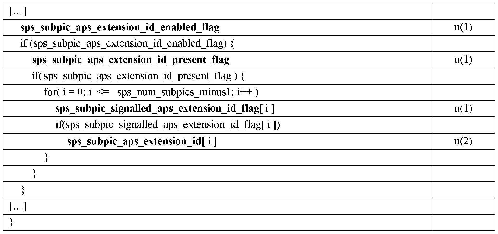
The apsld variable is equal to the result of a bit-wise AND operation (&) between the adaptation_parameter_set_id syntax element (providing the APS identifier) and the binary mask 0x07 in hexadecimal representation. The apsExtld variable is equal to the result of the arithmetic right shift operation (») of the two's complement integer representation of adpatation_parameter_set_id by 3 binary digits.
Based on the apsld and apsExtld variables, the slice and/or picture headers may refer to an APS using the following semantics for their syntax elements:
slice_alf_aps_id_luma[ i ] specifies the apsld of the i-th ALF APS that the luma component of the slice refers to.
The i-th ALF APS that the slice refers to is the APS NAL unit having the apsld equal to slice_alf_aps_id_luma[ i ] and having the apsExtld equal to SubpicAPSExtensionldList[ SubPicldx ].
The Temporalld of the APS NAL unit having aps_params_type equal to ALF_APS, having the apsld equal to slice_alf_aps_id_luma[ i ] and having the apsExtld equal to SubpicAPSExtensionldList[ SubPicldx ] may be less than or equal to the Temporalld of the coded slice NAL unit.
When slice_alf_enabled_flag is equal to 1 and slice_alf_aps_id_luma[ i ] is not present, the value of slice_alf_aps_id_luma[ i ] is inferred to be equal to the value of pic_alf_aps_id_luma[i]
slice_alf_aps_id_chroma specifies the apsld of the ALF APS that the chroma component of the slice refers to.
The APS that the slice refers to is the APS NAL unit having the apsld equal to slice_alf_aps_id_chroma and having the apsExtld equal to SubpicAPSExtensionldl_ist[ SubPicldx ].
The Temporalld of the APS NAL unit having aps_params_type equal to ALF_APS,— apsld equal to slice_alf_aps_id_chroma and apsExtld equal to SubpicAPSExtensionldList[ SubPicldx ] may be less than or equal to the Temporalld of the coded slice NAL unit. pic_alf_aps_id_luma[ i ] specifies the apsld of the i-th ALF APS that the luma component of the slices associated with the PH refers to.
The i-th ALF APS that the slice associated with the PH refers to is the APS NAL unit having apsld equal to pic_alf_aps_id_luma[ i ] and having the apsExtld equal to SubpicAPSExtensionldList[ SubPicldx ].
The value of alf_luma_filter_signal_flag of the APS NAL unit having aps_params_type equal to ALF_APS, having apsld equal to pic_alf_aps_id_luma[ i ] and having the apsExtld equal to SubpicAPSExtensionldList[ SubPicldx ] shall be equal to 1.
pic_alf_aps_id_chroma specifies the adaptation_parameter_set_id of the ALF APS that the chroma component of the slices associated with the PH refers to.
The ALF APS that the slice associated with the PH refers to is the APS NAL unit having apsld equal to pic_alf_aps_id_chroma and having the apsExtld equal to SubpicAPSExtensionldList[ SubPicldx ]. The value of alf_chroma_filter_signal_flag of the APS NAL unit having aps_params_type equal to ALF_APS, apsld equal to pic_alf_aps_id_chroma and having the apsExtld equal to SubpicAPSExtensionldList[ SubPicldx ] may be equal to IThis variant is illustrated with an example using 7 bits for the adaptation_parametrer_set_id syntax element with 3 used bits and 4 available bits used for an aps extension identifier. However, the invention works whatever the number of bits N used to encode the adaptation_parameter_set_id. Let us M be the bits which are used for the value range, then N-M bits could be used for the aps extension identifier.
In another embodiment, the second identification information is used for another Parameter Set type typically the PPS. For example, a bitstream contains at least two
sub-pictures with different tile grids. Since the tile grid is specified in the PPS, the number of activated PPS for each picture may be high. As a result, when merging different bitstreams there is a high risk of having two PPS with different coding parameters but same PPS identifiers. The merging process would also have to rewrite the PPS identifiers and modify the tile group headers to replace the value of the identifier of PPS that applies to the tile group with the new rewritten value.
Similarly, to the APS, the PPS may include an extension identifier to resolve PPS identifiers collision. When decoding a tile group, the decoder activates the PPS that has an identifier (for example, picture_parameter_set_id) equal to the value of tile_group_pic_parameter_set_id identifier and an extension identifier (for example pps_extension_id) equal to the extension identifier (for example sub_pic_ps_extension_id[i]) associated with the sub-picture of the tile group typically in the SPS NAL unit.
For example, the Sequence Parameters Set includes the following syntax elements:

- signalled_ps_id_extension_flag equal to 1 specifies the presence of sub_pic_ps_extension_id [ i ] in the SPS. signalled_ps_id_extension_flag equal to 0 specifies the absence of the sub_pic_ps_extension_id [ i ] in the SPS.
- sub_pic_ps_extension_id [ i ] specifies the sub-picture extension ID of the i-th sub-picture, when present. When not present, the sub_pic_ps_extension_id [ i ] is inferred equal to 0, for each i in the range of 0 to num_sub_pics_minus1 inclusive.
For example , the syntax of the Picture Parameter Set is the following:

For example, the semantics of syntax elements are the following:
- picture_parameter_set_id provides an identifier for the PPS for reference by other syntax elements.
- pps_id_extension_flag equal to 1 specifies the presence of pps_extension_id in the PPS. pps_extension_flag equal to 0 specifies the absence of the pps_extension_id in the PPS.
- pps_extension_id when present, provides a PPS extended identifier for reference by other syntax elements. The value of pps_extension_id shall be in the range of 0 to 31. When not present the value of pps_extension_id is inferred to be equal 0. The syntax of the tile group header remains unchanged. The semantics of some syntax elements of the tile group header is the following:
- tile_group_pic_parameter_set_id specifies the identifier of the PPS in use.
The value of tile_group_pic_parameter_set_id shall be in the range of 0 to 63, inclusive.
The PPS in use is the PPS NAL unit having picture_parameter_set_id equal to tile_group_pic_parameter_set_id and the pps_extension_id equal to sub_pic_ps_extension_id [SubPicldx[ tile_group_sub_pic_id ]]. It is a requirement of bitstream conformance that the value of Temporalld of the current picture shall be greater than or equal to the value of Temporalld of the PPS that has pps_pic_parameter_set_id equal to tile_group_pic_parameter_set_id and the pps_extension_id equal to sub_pic_ps_extension_id
[SubPicldx[ tile_group_sub_pic_id ]]. The variable SubPicldx is an array for which the indexes are identifiers of sub-pictures and the values are the index of the sub- pictures in the declaration order used in the SPS.
- tile_group_aps_id specifies the identifier of the APS in use.
The APS in use is the APS NAL unit having adaptation_parameter_set_id equal to tile_group_aps_id and the aps_extension_id equal to sub_pic_ps_extension_id [SubPicldx[ tile_group_sub_pic_id ]].
The Temporalld of the APS NAL unit having adaptation_parameter_set_id equal to tile_group_aps_id and the aps_extension_id equal to sub_pic_ps_extension_id [SubPicldx[ tile_group_sub_pic_id ]] shall be less than or equal to the Temporalld of the coded tile group NAL unit.
When multiple APSs with the same value of adaptation_parameter_set_id and aps_extension_id are referred to by two or more tile groups of the same picture, the multiple APSs with the same value of adaptation_parameter_set_id and aps_extension_id shall have the same content.
In this example, the same extension identifier associated with the sub-picture is used for both the APS and the PPS identification. In some embodiments, a different extension identifier may be used, one for the APS and one for the PPS.
In a variant, to avoid coding one extension identifier for each sub-picture, a second flag indicates the presence of the extension identifier for each sub-picture instead of a single flag for all the sub-pictures. The syntax of the SPS NAL units becomes:


For example, the semantics of some of the syntax elements of the PPS is the following:
- signalled_ps_id_extension_flag [ i ] equal to 1 specifies the presence of the sub_pic_ps_extension_id [ i ] in the SPS for the i-th sub-picture. signalled_ps_id_extension_flag equal to 0 specifies the absence of the sub_pic_ps_extension_id [ i ] in the SPS for the i-th sub-picture.
- sub_pic_ps_extension_id [ i ] specifies the parameter sets extension ID of the i- th sub-picture, when present. When not present, the sub_pic_ps_extension_id [ i ] is inferred equal to 0, for each i in the range of 0 to num_sub_pics_minus1 inclusive.
Figure 15 is a schematic block diagram of a computing device 1500 for implementation of one or more embodiments of the invention. The computing device 1500 may be a device such as a microcomputer, a workstation or a light portable device.
The computing device 1500 comprises a communication bus connected to:
- a central processing unit 1501 , such as a microprocessor, denoted CPU;
- a random access memory 1502, denoted RAM, for storing the executable code of the method of embodiments of the invention as well as the registers adapted to record variables and parameters necessary for implementing the method according to
embodiments of the invention, the memory capacity thereof can be expanded by an optional RAM connected to an expansion port, for example;
- a read only memory 1503, denoted ROM, for storing computer programs for implementing embodiments of the invention;
- a network interface 1504 is typically connected to a communication network over which digital data to be processed are transmitted or received. The network interface 1504 can be a single network interface, or composed of a set of different network interfaces (for instance wired and wireless interfaces, or different kinds of wired or wireless interfaces). Data packets are written to the network interface for transmission or are read from the network interface for reception under the control of the software application running in the CPU 1501 ;
- a user interface 1505 may be used for receiving inputs from a user or to display information to a user;
- a hard disk 1506 denoted HD may be provided as a mass storage device; - an I/O module 1507 may be used for receiving/sending data from/to external devices such as a video source or display.
The executable code may be stored either in read only memory 1503, on the hard disk 1506 or on a removable digital medium such as for example a disk. According to a variant, the executable code of the programs can be received by means of a communication network, via the network interface 1504, in order to be stored in one of the storage means of the communication device 1500, such as the hard disk 1506, before being executed.
The central processing unit 1501 is adapted to control and direct the execution of the instructions or portions of software code of the program or programs according to embodiments of the invention, which instructions are stored in one of the aforementioned storage means. After powering on, the CPU 1501 is capable of executing instructions from main RAM memory 1502 relating to a software application after those instructions have been loaded from the program ROM 1503 or the hard disk (HD) 1506, for example. Such a software application, when executed by the CPU 1501 , causes the steps of the flowcharts of the invention to be performed.
Any step of the algorithms of the invention may be implemented in software by execution of a set of instructions or program by a programmable computing machine, such as a PC (“Personal Computer”), a DSP (“Digital Signal Processor”) or a microcontroller; or else implemented in hardware by a machine or a dedicated
component, such as an FPGA (“Field-Programmable Gate Array”) or an ASIC (“Application-Specific Integrated Circuit”).
Although the present invention has been described herein above with reference to specific embodiments, the present invention is not limited to the specific embodiments, and modifications will be apparent to a skilled person in the art which lie within the scope of the present invention.
Many further modifications and variations will suggest themselves to those versed in the art upon making reference to the foregoing illustrative embodiments, which are given by way of example only and which are not intended to limit the scope of the invention, that being determined solely by the appended claims. In particular the different features from different embodiments may be interchanged, where appropriate.
Each of the embodiments of the invention described above can be implemented solely or as a combination of a plurality of the embodiments. Also, features from different embodiments can be combined where necessary or where the combination of elements or features from individual embodiments in a single embodiment is beneficial.
Each feature disclosed in this specification (including any accompanying claims, abstract and drawings) may be replaced by alternative features serving the same, equivalent or similar purpose, unless expressly stated otherwise. Thus, unless expressly stated otherwise, each feature disclosed is one example only of a generic series of equivalent or similar features.
The information coded in the Tile Group may also be encoded in all the Tile Group Segment headers. Alternatively, the information is encoded only in the independent tile group segment header to reduce the size of the dependent tile group segment headers.
The information coded in the Picture Parameter Set PPS could also be encoded in other non-VCL units like a Video Parameter Set VPS, Sequence Parameter Set SPS or the DPS or new units like Layer Parameter Set, or Tile Group Parameter Set. These units define parameters valid for several pictures and thus there are at a higher hierarchical level than the tile group units or the APS units in the video bitstream. The tile group units are valid only inside one picture. The APS units can be valid for some pictures but their usage changes rapidly from one picture to another.
The Adaptation Parameter Set unit (APS) contains parameters defined for the Adaptive Loop Filter (ALF). In some variants, the APS may contain several loop filters parameter sets with different characteristics. The CTU using a particular APS can then select which particular loop filter parameter set is used. In another variant, the video can also use other types of filters (SAO, deblocking filters, post-processing filter, Reshaper
or LMCS model based filtering, denoising ...). Some parameters for some other filters (in-loop and out of loop filters) could also be encoded and stored in some other Parameter Set NAL units (filter parameter set units) referenced by the tile group. The same invention could be applied to these new types of units.
In the claims, the word“comprising” does not exclude other elements or steps, and the indefinite article“a” or“an” does not exclude a plurality. The mere fact that different features are recited in mutually different dependent claims does not indicate that a combination of these features cannot be advantageously used.
Claims
1. A method of encoding video data comprising pictures into a bitstream of logical units, pictures being spatially divided into picture portions, picture portions being spatially divided into sub-portions, the method comprising:
- determining a parameter set applying to a sub-portion;
- determining a first identification information of the determined parameter set;
- determining a second identification information associated with the sub- portion;
- encoding the sub-portion into a first logical unit comprising the first identification information;
- encoding the parameter set into a second logical unit comprising a parameter set identifier determined based on the first identification information and on the second identification information; and,
- encoding the association between the second identification information and the sub-portion and into a logical unit.
2. The method of claim 1 , wherein the association between the second identification information and the sub-portion is an association between the second identification information and a picture portion the sub-portion belongs to.
3. The method of claim 1 or 2, wherein:
- the second identification information is an extension identifier; and,
- the parameter set identifier comprises the first identification information and the extension identifier.
4. The method of claim 1 or 2, wherein:
- the second identification information is an offset; and,
- the parameter set identifier is the addition of the first identification information and of the offset.
5. The method of claim 1 or 2, wherein:
the second identification information is an index of a parameter set.
6. The method of claim 1 or 2, wherein the association between the second identification information and the sub-portion is encoded into a third logical unit.
7. The method of claim 6, wherein the second and third logical units are parameter set logical units applying at different levels of the bitstream.
8. The method of claim 1 or 2, wherein the association between the second identification information and the sub-portion is encoded into the second logical unit.
9. The method of claim 5, wherein a plurality of parameter sets are determined, the method further comprising:
- encoding the plurality of parameter sets into the second logical unit, each parameter set being associated with an index, the second logical unit comprising for each picture portion, the association of an index of the picture portions and the index of a parameter set.
10. The method of any one claim 1 to 9, wherein the parameter set is a filter parameter set.
11. The method of any one claim 1 to 9, wherein the parameter set is a picture parameter set.
12. A method for decoding a bitstream of logical units of video data comprising pictures, pictures being divided into picture portions, picture portions being spatially divided into sub-portions, the method comprising:
- parsing a first logical unit comprising a sub-portion to determine a first identification information of a parameter set applying to the sub-portion;
- parsing a second logical unit comprising the association between a second identification information and the sub-portion;
- determining a parameter set identifier based on the first identification information and the second identification information;
- decoding a logical unit comprising the parameter set identified by the parameter set identifier;
- decoding the sub-portion comprised in the first logical unit using the decoded parameter set.
13. The method of claim 12, wherein the association between the second identification information and the sub-portion is an association between the second identification information and the picture portion the sub-portion belongs to.
14. The method of claim 12 or 13, wherein:
- the second identification information is an extension identifier; and,
- the parameter set identifier comprises the first identification information and the extension identifier.
15. The method of claim 12 or 13, wherein:
- the second identification information is an offset; and,
- the parameter set identifier is the addition of the first identification information and the offset.
16. The method of claim 12 or 13, wherein:
- the second identification information is an index of a parameter set.
17. The method of claim 12 or 13, wherein the logical unit comprising the parameter set is a third logical unit.
18. The method of claim 17, wherein the second and third logical units are parameter set logical units applying at different levels of the bitstream.
19. The method of claim 12 or 13, wherein the logical unit comprising the parameter set is the second logical unit.
20. The method of claim 16, wherein a plurality of parameter sets are determined, the method further comprising:
- decoding the plurality of parameter sets from the second logical unit, each parameter set being associated with an index, the second logical unit comprising for each sub-portion, the association of an index of the sub portion and the index of a parameter set.
21. The method of any one claim 12 to 20, wherein the parameter set is a filter parameter set.
22. The method of any one claim 12 to 20, wherein the parameter set is a picture parameter set.
23. A method for merging sub-portions from a plurality of original bitstreams of video data into a resulting bitstream, bitstreams being composed of logical units comprising pictures, pictures being divided into picture portions, picture portions being spatially divided into sub-portions, the method comprising:
- parsing the logical units comprising the sub-portions to determine a first identification information of a parameter set associated with each sub portion;
- extracting logical units comprising a parameter set applying to a sub- portion, the logical unit being identified by the first identification information;
- encoding a logical unit comprising the association of a second identification information with a sub-portion for each sub-portion;
- encoding each extracted logical unit comprising a parameter set into a logical unit comprising the parameter set and a parameter set identifier determined based on the first identification information and the second identification information;
- generating the resulting bitstream comprising the logical units comprising the sub-portions, the encoded logical unit comprising the association of a second identification information with the sub-portions and the encoded logical units comprising the parameter sets.
24. The method of claim 23, wherein the association between the second identification information and the sub-portion is an association between the
second identification information and the picture portion the sub-portion belongs to.
25. The method of claim 23 or 24, wherein:
- the second identification information is an extension identifier; and
- the parameter set identifier comprises the first identification information and the extension identifier.
26. The method of claim 23 or 24, wherein:
- the second identification information is an offset; and
- the parameter set identifier is the addition of the first identification information and of the offset.
27. The method of claim 23 or 24, wherein:
- the second identification information is an index of a parameter set.
28. The method of any one claim 23 to 27, wherein the parameter set is a filter parameter set.
29. The method of any one claim 23 to 27, wherein the parameter set is a picture parameter set.
30. A method of generating a file comprising a bitstream of logical units of encoded video data comprising pictures, pictures being divided into picture portions, picture portions being spatially divided into sub-portions, the method comprising:
- encoding the bitstream according to any one of claims 1 to 11 ;
- generating a first track comprising the logical units containing the parameter sets, and the logical unit containing the association between the second identification information and the sub-portion;
- generating for a sub-portion, a track containing the logical unit containing the sub-portion; and,
- generating the file comprising the generated tracks.
31. A bitstream of logical units, the bitstream comprising encoded video data comprising pictures, pictures being divided into picture portions, picture portions being spatially divided into sub-portions, the bitstream comprising:
- a first logical unit comprising a sub-portion;
- a second logical unit comprising a parameter set applying to the sub portion and a parameter set identifier determined based on a first identification information of the parameter set and on a second identification information associated with the sub-portion; and,
- a logical unit comprising the association between the second identification information and the sub-portion.
32. A computer program product for a programmable apparatus, the computer program product comprising a sequence of instructions for implementing a method according to any one of claims 1 to 21 , when loaded into and executed by the programmable apparatus.
33. A computer-readable storage medium storing instructions of a computer program for implementing a method according to any one of claims 1 to 21.
34. A computer program which upon execution causes the method of any one of claims 1 to 21 to be performed.
Applications Claiming Priority (10)
| Application Number | Priority Date | Filing Date | Title |
|---|---|---|---|
| GB1902829.9 | 2019-03-01 | ||
| GBGB1902829.9A GB201902829D0 (en) | 2019-03-01 | 2019-03-01 | Method and apparatus for encoding and decoding a video bitsream for merging regions of interest |
| GB1903379.4 | 2019-03-12 | ||
| GB1903379.4A GB2581852A (en) | 2019-03-01 | 2019-03-12 | Method and apparatus for encoding and decoding a video bitstream for merging regions of interest |
| GB1904461.9A GB2581855A (en) | 2019-03-01 | 2019-03-29 | Method and apparatus for encoding and decoding a video bitstream for merging regions of interest |
| GB1904461.9 | 2019-03-29 | ||
| GB1918658.4 | 2019-12-17 | ||
| GBGB1918658.4A GB201918658D0 (en) | 2019-03-01 | 2019-12-17 | Method and apparatus for encoding and decoding a video bitstream for merging regions of interest |
| GB2000479.2 | 2020-01-13 | ||
| GB2000479.2A GB2582206B (en) | 2019-03-01 | 2020-01-13 | Method and apparatus for encoding and decoding a video bitstream for merging regions of interest |
Publications (1)
| Publication Number | Publication Date |
|---|---|
| WO2020178065A1 true WO2020178065A1 (en) | 2020-09-10 |
Family
ID=66377319
Family Applications (1)
| Application Number | Title | Priority Date | Filing Date |
|---|---|---|---|
| PCT/EP2020/054831 Ceased WO2020178065A1 (en) | 2019-03-01 | 2020-02-25 | Method and apparatus for encoding and decoding a video bitstream for merging regions of interest |
Country Status (2)
| Country | Link |
|---|---|
| GB (5) | GB201902829D0 (en) |
| WO (1) | WO2020178065A1 (en) |
Cited By (5)
| Publication number | Priority date | Publication date | Assignee | Title |
|---|---|---|---|---|
| CN114205609A (en) * | 2020-09-17 | 2022-03-18 | 脸萌有限公司 | Sub-picture track reference and processing |
| WO2023047014A1 (en) * | 2021-09-23 | 2023-03-30 | Nokia Technologies Oy | An apparatus, a method and a computer program for video coding and decoding |
| CN116018809A (en) * | 2020-09-15 | 2023-04-25 | 索尼集团公司 | Information processing device and method |
| US12167002B2 (en) | 2019-06-24 | 2024-12-10 | Lg Electronics Inc. | Video or image coding based on mapping of luma samples and scaling of chroma samples |
| US12238340B2 (en) | 2019-12-20 | 2025-02-25 | Canon Kabushiki Kaisha | High level syntax for video coding and decoding |
Families Citing this family (17)
| Publication number | Priority date | Publication date | Assignee | Title |
|---|---|---|---|---|
| PL4221213T3 (en) * | 2019-01-09 | 2024-11-18 | Huawei Technologies Co., Ltd. | A video encoder, a video decoder and corresponding methods |
| US11683487B2 (en) * | 2019-03-26 | 2023-06-20 | Qualcomm Incorporated | Block-based adaptive loop filter (ALF) with adaptive parameter set (APS) in video coding |
| KR20260032632A (en) * | 2019-04-15 | 2026-03-09 | 엘지전자 주식회사 | Scaling list-based video coding method and apparatus |
| WO2020233660A1 (en) | 2019-05-21 | 2020-11-26 | Beijing Bytedance Network Technology Co., Ltd. | Syntax-based motion candidate derivation in sub-block merge mode |
| CN114270823B (en) * | 2019-06-24 | 2025-08-15 | Lg电子株式会社 | Video or image coding based on luma mapping and chroma scaling |
| EP3997869A4 (en) | 2019-08-10 | 2022-10-26 | Beijing Bytedance Network Technology Co., Ltd. | SUBPICTURE DEPENDENT SIGNALING IN VIDEO STREAMS |
| CN121173962A (en) | 2019-08-16 | 2025-12-19 | 华为技术有限公司 | ALF APS constraints in video coding |
| EP4035372A4 (en) | 2019-09-23 | 2022-11-23 | Telefonaktiebolaget LM Ericsson (publ) | Segment position signalling with subpicture slice position deriving |
| CN114631321B (en) | 2019-10-18 | 2024-04-12 | 北京字节跳动网络技术有限公司 | Interaction between sub-pictures and loop filtering |
| CN115280774B (en) | 2019-12-02 | 2025-08-19 | 抖音视界有限公司 | Method, apparatus, and non-transitory computer readable storage medium for visual media processing |
| EP4066387A4 (en) * | 2019-12-27 | 2023-02-15 | ByteDance Inc. | Subpicture signaling in parameter sets |
| WO2021142370A1 (en) | 2020-01-09 | 2021-07-15 | Bytedance Inc. | Constraints on value ranges in video bitstreams |
| KR20220157950A (en) | 2020-03-23 | 2022-11-29 | 베이징 바이트댄스 네트워크 테크놀로지 컴퍼니, 리미티드 | Prediction refinement for affine merge and affine motion vector prediction modes |
| GB2593543B (en) | 2020-03-27 | 2023-04-19 | Canon Kk | Video coding and decoding |
| CN113453011B (en) * | 2020-03-27 | 2025-07-25 | 腾讯美国有限责任公司 | Method and apparatus for decoding encoded video bitstream |
| WO2022050166A1 (en) * | 2020-09-04 | 2022-03-10 | パナソニック インテレクチュアル プロパティ コーポレーション オブ アメリカ | Reproduction device, transmission device, reproduction method, and transmission method |
| GB2605955B (en) * | 2021-04-13 | 2024-10-30 | Canon Kk | Method and apparatus for encapsulating encoded media data in a media file |
Family Cites Families (4)
| Publication number | Priority date | Publication date | Assignee | Title |
|---|---|---|---|---|
| US9516308B2 (en) * | 2012-04-27 | 2016-12-06 | Qualcomm Incorporated | Parameter set updates in video coding |
| GB2550604A (en) * | 2016-05-24 | 2017-11-29 | Canon Kk | Method, device, and computer program for encapsulating and parsing timed media data |
| US10506230B2 (en) * | 2017-01-04 | 2019-12-10 | Qualcomm Incorporated | Modified adaptive loop filter temporal prediction for temporal scalability support |
| US20190238845A1 (en) * | 2018-01-26 | 2019-08-01 | Qualcomm Incorporated | Adaptive loop filtering on deblocking filter results in video coding |
-
2019
- 2019-03-01 GB GBGB1902829.9A patent/GB201902829D0/en not_active Ceased
- 2019-03-12 GB GB1903379.4A patent/GB2581852A/en not_active Withdrawn
- 2019-03-29 GB GB1904461.9A patent/GB2581855A/en not_active Withdrawn
- 2019-12-17 GB GBGB1918658.4A patent/GB201918658D0/en not_active Ceased
-
2020
- 2020-01-13 GB GB2000479.2A patent/GB2582206B/en not_active Expired - Fee Related
- 2020-02-25 WO PCT/EP2020/054831 patent/WO2020178065A1/en not_active Ceased
Non-Patent Citations (2)
| Title |
|---|
| BROSS B ET AL: "Versatile Video Coding (Draft 4)", no. JVET-M1001, 27 February 2019 (2019-02-27), XP030202598, Retrieved from the Internet <URL:http://phenix.int-evry.fr/jvet/doc_end_user/documents/13_Marrakech/wg11/JVET-M1001-v5.zip JVET-M1001-v5.docx> [retrieved on 20190227] * |
| OUEDRAOGO N ET AL: "[AHG17/AHG12] On APS id for bitstream merging for VVC", no. JVET-N0191, 12 March 2019 (2019-03-12), XP030202674, Retrieved from the Internet <URL:http://phenix.int-evry.fr/jvet/doc_end_user/documents/14_Geneva/wg11/JVET-N0191-v1.zip JVET-N0191.docx> [retrieved on 20190312] * |
Cited By (6)
| Publication number | Priority date | Publication date | Assignee | Title |
|---|---|---|---|---|
| US12167002B2 (en) | 2019-06-24 | 2024-12-10 | Lg Electronics Inc. | Video or image coding based on mapping of luma samples and scaling of chroma samples |
| US12238340B2 (en) | 2019-12-20 | 2025-02-25 | Canon Kabushiki Kaisha | High level syntax for video coding and decoding |
| CN116018809A (en) * | 2020-09-15 | 2023-04-25 | 索尼集团公司 | Information processing device and method |
| CN114205609A (en) * | 2020-09-17 | 2022-03-18 | 脸萌有限公司 | Sub-picture track reference and processing |
| WO2023047014A1 (en) * | 2021-09-23 | 2023-03-30 | Nokia Technologies Oy | An apparatus, a method and a computer program for video coding and decoding |
| US20240291981A1 (en) * | 2021-09-23 | 2024-08-29 | Nokia Technologies Oy | An apparatus, a method and a computer program for video coding and decoding |
Also Published As
| Publication number | Publication date |
|---|---|
| GB201918658D0 (en) | 2020-01-29 |
| GB201904461D0 (en) | 2019-05-15 |
| GB201903379D0 (en) | 2019-04-24 |
| GB201902829D0 (en) | 2019-04-17 |
| GB2581855A (en) | 2020-09-02 |
| GB2582206A (en) | 2020-09-16 |
| GB202000479D0 (en) | 2020-02-26 |
| GB2582206B (en) | 2022-04-27 |
| GB2581852A (en) | 2020-09-02 |
Similar Documents
| Publication | Publication Date | Title |
|---|---|---|
| WO2020178065A1 (en) | Method and apparatus for encoding and decoding a video bitstream for merging regions of interest | |
| US20220217355A1 (en) | Method and apparatus for encoding and decoding a video bitstream for merging regions of interest | |
| US20250016314A1 (en) | Method and apparatus for encoding and decoding a video stream with subpictures | |
| JP7675768B2 (en) | Video coding with subpicture, slice, and tile support | |
| GB2584723A (en) | Method, device, and computer program for coding and decoding a picture | |
| US20210092359A1 (en) | Method, device, and computer program for coding and decoding a picture | |
| CN115914628A (en) | Method and apparatus for encoding or decoding video data having frame portions | |
| WO2020178144A1 (en) | Method and apparatus for encoding and decoding a video bitstream for merging regions of interest | |
| JP2023024970A (en) | Improved tile address signaling in video encoding and decoding | |
| HK40129084A (en) | Method and apparatus for encoding video data into bitstream, method and apparatus for decoding bitstream of video data, computer program product, and storage medium | |
| HK40129086A (en) | Method and apparatus for encoding video data into bitstream, method and apparatus for decoding bitstream of video data, computer program product, and storage medium | |
| HK40129087A (en) | Method and apparatus for encoding video data into bitstream, method and apparatus for decoding bitstream of video data, computer program product, and storage medium | |
| HK40129083A (en) | Method and apparatus for encoding video data into bitstream, method and apparatus for decoding bitstream of video data, computer program product, and storage medium | |
| HK40128004A (en) | Method and apparatus for encoding video data into bitstream, method and apparatus for decoding bitstream of video data, computer program product, and storage medium |
Legal Events
| Date | Code | Title | Description |
|---|---|---|---|
| 121 | Ep: the epo has been informed by wipo that ep was designated in this application |
Ref document number: 20707078 Country of ref document: EP Kind code of ref document: A1 |
|
| NENP | Non-entry into the national phase |
Ref country code: DE |
|
| 122 | Ep: pct application non-entry in european phase |
Ref document number: 20707078 Country of ref document: EP Kind code of ref document: A1 |