WO2020175588A1 - 三次元データ符号化方法、三次元データ復号方法、三次元データ符号化装置、及び三次元データ復号装置 - Google Patents
三次元データ符号化方法、三次元データ復号方法、三次元データ符号化装置、及び三次元データ復号装置 Download PDFInfo
- Publication number
- WO2020175588A1 WO2020175588A1 PCT/JP2020/007869 JP2020007869W WO2020175588A1 WO 2020175588 A1 WO2020175588 A1 WO 2020175588A1 JP 2020007869 W JP2020007869 W JP 2020007869W WO 2020175588 A1 WO2020175588 A1 WO 2020175588A1
- Authority
- WO
- WIPO (PCT)
- Prior art keywords
- dimensional
- data
- information
- dimensional data
- encoded
- Prior art date
- Legal status (The legal status is an assumption and is not a legal conclusion. Google has not performed a legal analysis and makes no representation as to the accuracy of the status listed.)
- Ceased
Links
Classifications
-
- H—ELECTRICITY
- H04—ELECTRIC COMMUNICATION TECHNIQUE
- H04N—PICTORIAL COMMUNICATION, e.g. TELEVISION
- H04N19/00—Methods or arrangements for coding, decoding, compressing or decompressing digital video signals
- H04N19/50—Methods or arrangements for coding, decoding, compressing or decompressing digital video signals using predictive coding
- H04N19/597—Methods or arrangements for coding, decoding, compressing or decompressing digital video signals using predictive coding specially adapted for multi-view video sequence encoding
-
- G—PHYSICS
- G06—COMPUTING OR CALCULATING; COUNTING
- G06F—ELECTRIC DIGITAL DATA PROCESSING
- G06F7/00—Methods or arrangements for processing data by operating upon the order or content of the data handled
- G06F7/76—Arrangements for rearranging, permuting or selecting data according to predetermined rules, independently of the content of the data
-
- G—PHYSICS
- G06—COMPUTING OR CALCULATING; COUNTING
- G06T—IMAGE DATA PROCESSING OR GENERATION, IN GENERAL
- G06T7/00—Image analysis
- G06T7/70—Determining position or orientation of objects or cameras
- G06T7/73—Determining position or orientation of objects or cameras using feature-based methods
- G06T7/75—Determining position or orientation of objects or cameras using feature-based methods involving models
-
- G—PHYSICS
- G06—COMPUTING OR CALCULATING; COUNTING
- G06T—IMAGE DATA PROCESSING OR GENERATION, IN GENERAL
- G06T9/00—Image coding
- G06T9/001—Model-based coding, e.g. wire frame
-
- G—PHYSICS
- G06—COMPUTING OR CALCULATING; COUNTING
- G06T—IMAGE DATA PROCESSING OR GENERATION, IN GENERAL
- G06T9/00—Image coding
- G06T9/40—Tree coding, e.g. quadtree, octree
Definitions
- Three-dimensional data encoding method three-dimensional data decoding method, three-dimensional data encoding device, and three-dimensional data decoding device
- the present disclosure relates to a three-dimensional data encoding method, a three-dimensional data decoding method, a three-dimensional data encoding device, and a three-dimensional data decoding device.
- a representation method called a point cloud that represents the shape of a three-dimensional structure by a point cloud in a three-dimensional space.
- the point cloud stores the position and color of the point cloud. It is expected that point clouds will become the main method of representing 3D data, but the amount of data for point clouds is very large. Therefore, in the storage or transmission of 3D data, as in the case of 2D moving images (for example, MPEG standardized by MPEG-480 or 1 to 1M, etc.) A certain amount of compression is essential.
- Patent Document 1 International Publication No. 2 0 1 4/0 2 0 6 6 3
- An object of the present disclosure is to provide a three-dimensional data encoding method, a three-dimensional data decoding method, a three-dimensional data encoding device, or a three-dimensional data decoding device that can improve encoding efficiency.
- a three-dimensional data encoding method is a three-dimensional data encoding method for encoding a plurality of three-dimensional points, wherein the plurality of three-dimensional points arranged in a predetermined order.
- the data order of the attribute information is rearranged, the rearranged attribute information of the plurality of three-dimensional points is encoded based on the data order, sequence information indicating the predetermined order, and the plurality of encoded three-dimensional information are encoded.
- a three-dimensional data decoding method is a three-dimensional data decoding method for decoding a plurality of coded three-dimensional element points, wherein the plurality of three-dimensional data arranged in a predetermined order.
- the data order of the attribute information of the original points is rearranged, and the rearranged attribute information of the plurality of three-dimensional points is the plurality of tertiary original points encoded based on the data order, the encoded
- a bit stream including attribute information of a plurality of three-dimensional points and order information indicating the predetermined order is acquired, and the attribute information of the encoded plurality of three-dimensional points is encoded.
- Decoding is performed based on the data order of the attribute information of a plurality of three-dimensional points.
- the present disclosure can provide a three-dimensional data encoding method, a three-dimensional data decoding method, a three-dimensional data encoding device, or a three-dimensional data decoding device that can improve encoding efficiency.
- ⁇ 0 2020/175588 3 (:171? 2020/007869
- FIG. 1 is a diagram showing a configuration of encoded three-dimensional data according to the first embodiment.
- FIG. 2 is a diagram illustrating an _ example of a prediction structure between 3 ⁇ belonging to the lowermost layer of the ⁇ 3 according to the first embodiment.
- FIG. 3 is a diagram showing an example of a prediction structure between layers according to the first embodiment.
- FIG. 4 is a diagram showing an example of an encoding order of 0 0 3 according to the first embodiment.
- FIG. 5 is a diagram showing an example of an encoding order of 0 0 3 according to the first embodiment.
- FIG. 6 is a block diagram of a three-dimensional data encoding device according to the first embodiment.
- FIG. 7 is a flowchart of the encoding process according to the first embodiment.
- FIG. 8 is a block diagram of a three-dimensional data decoding device according to the first embodiment.
- FIG. 9 is a flowchart of the decoding process according to the first embodiment.
- FIG. 10 is a diagram showing an example of meta information according to the first embodiment.
- Fig. 11 shows an embodiment It is a figure which shows the structural example.
- FIG. 12 is a diagram showing an operation example of a server and a client according to the second embodiment.
- FIG. 13 is a diagram showing an operation example of a server and a client according to the second embodiment.
- FIG. 14 is a diagram showing an operation example of a server and a client according to the second embodiment.
- FIG. 15 is a diagram showing an operation example of a server and a client according to the second embodiment.
- FIG. 16 is a block diagram of a three-dimensional data encoding device according to a second embodiment.
- FIG. 17 is a flowchart of the encoding process according to the second embodiment. ⁇ 0 2020/175 588 4 ⁇ (: 171? 2020 /007869
- FIG. 18 is a block diagram of a three-dimensional data decoding device according to a second embodiment.
- FIG. 19 is a flowchart of a decoding process according to the second embodiment.
- FIG. 20 shows an embodiment. It is a figure which shows the structural example.
- Fig. 21 shows the embodiment
- FIG. 22 is a diagram showing a configuration example of 3!_ 0 according to the second embodiment.
- Fig. 23 shows an embodiment
- FIG. 24 is a block diagram of a three-dimensional data creation device according to a third embodiment.
- FIG. 25 is a block diagram of a three-dimensional data transmission apparatus according to the third embodiment.
- FIG. 26 is a block diagram of a three-dimensional information processing apparatus according to the fourth embodiment.
- FIG. 27 is a block diagram of a three-dimensional data creation device according to a fifth embodiment.
- FIG. 28 is a diagram showing a configuration of a system according to a sixth embodiment.
- FIG. 29 is a block diagram of a client apparatus according to the sixth embodiment.
- FIG. 30 is a block diagram of a server according to the sixth embodiment.
- FIG. 31 is a flow chart of a three-dimensional data creation process by the client device according to the sixth embodiment.
- FIG. 32 is a flowchart of sensor information transmission processing by the client device according to the sixth embodiment.
- FIG. 33 is a flowchart of the three-dimensional data creation processing by the server according to the sixth embodiment.
- FIG. 34 shows a three-dimensional map transmission process by the server according to the sixth embodiment. ⁇ 0 2020/175 588 5 ⁇ (: 17 2020 /007869
- FIG. 35 is a diagram showing a configuration of a modified example of the system according to the sixth embodiment.
- FIG. 36 is a diagram showing configurations of a server and a client device according to the sixth embodiment.
- FIG. 37 is a block diagram of a three-dimensional data encoding device according to a seventh embodiment.
- FIG. 38 is a diagram showing an example of a prediction residual according to the seventh embodiment.
- FIG. 39 is a diagram showing an example of a volume according to the seventh embodiment.
- FIG. 40 is a diagram showing an example of an octree tree representation of a volume according to the seventh embodiment.
- FIG. 41 is a diagram showing an example of a bit string of a volume according to the seventh embodiment.
- FIG. 42 is a diagram showing an example of an octree tree representation of a volume according to the seventh embodiment.
- FIG. 43 is a diagram showing an example of a volume according to the seventh embodiment.
- FIG. 44 is a diagram for explaining the intra prediction process according to the seventh embodiment.
- FIG. 45 is a diagram for explaining the rotation and translation processing according to the seventh embodiment.
- FIG. 46 is a diagram showing an example of the syntax of the Ding application flag and Ding information according to the seventh embodiment.
- FIG. 47 is a diagram for explaining the inter prediction process according to the seventh embodiment.
- FIG. 48 is a block diagram of a three-dimensional data decoding device according to a seventh embodiment.
- FIG. 49 is a flowchart of the three-dimensional data encoding process by the three-dimensional data encoding device according to the seventh embodiment. ⁇ 0 2020/175 588 6 ⁇ (: 171? 2020 /007869
- FIG. 50 is a flow chart of a three-dimensional data decoding process by the three-dimensional data decoding device according to the seventh embodiment.
- FIG. 51 is a diagram showing an example of a three-dimensional point according to the eighth embodiment.
- FIG. 52 is a diagram showing an example of setting !_ ⁇ mouth according to the eighth embodiment.
- FIG. 53 is a diagram showing an example of a threshold value used for setting the mouth _! according to the eighth embodiment.
- FIG. 54 is a diagram showing an example of attribute information used for a prediction value according to the eighth embodiment.
- FIG. 55 is a diagram showing an example of an exponential Golomb code according to the eighth embodiment.
- FIG. 56 is a diagram showing a process for an exponential Golomb code according to the eighth embodiment.
- FIG. 57 is a diagram showing a syntax example of an attribute header according to the eighth embodiment.
- FIG. 58 is a diagram showing a syntax example of attribute data according to the eighth embodiment.
- FIG. 59 is a flowchart of the three-dimensional data encoding process according to the eighth embodiment.
- FIG. 60 is a flowchart of the attribute information encoding process according to the eighth embodiment.
- FIG. 61 is a diagram showing a process for an exponential Golomb code according to the eighth embodiment.
- FIG. 62 is a diagram showing an example of a reverse lookup table showing the relationship between the remaining codes and their values according to the eighth embodiment.
- FIG. 63 is a flowchart of the three-dimensional data decoding process according to the eighth embodiment.
- FIG. 64 is a flowchart of the attribute information decoding process according to the eighth embodiment. ⁇ 0 2020/175 588 7 ⁇ (: 171? 2020 /007869
- FIG. 65 is a block diagram of a three-dimensional data encoding device according to an eighth embodiment.
- FIG. 66 is a block diagram of a three-dimensional data decoding device according to the eighth embodiment.
- FIG. 67 is a flowchart of the three-dimensional data encoding process according to the eighth embodiment.
- FIG. 68 is a flowchart of the three-dimensional data decoding process according to the eighth embodiment.
- FIG. 6-9 is a diagram showing a first example of te _ table showing the predicted value calculated in each prediction mode according to the ninth embodiment.
- FIG. 70 is a diagram showing an example of attribute information used for a prediction value according to the ninth embodiment.
- FIG. 71 is a diagram showing a second example of a table showing prediction values calculated in each prediction mode according to the ninth embodiment.
- FIG. 72 is a diagram showing a third example of a table showing prediction values calculated in each prediction mode according to the ninth embodiment.
- FIG. 73 is a diagram showing a fourth example of a table showing prediction values calculated in each prediction mode according to the ninth embodiment.
- FIG. 74 is a diagram for explaining encoding of attribute information using eight to one according to the tenth embodiment.
- FIG. 75 is a diagram showing an example of setting a quantization scale for each layer according to the tenth embodiment.
- FIG. 76 is a diagram showing an example of a first code string and a second code string according to the tenth embodiment.
- FIG. 77 is a diagram showing an example of a trunk unary code according to the tenth embodiment.
- FIG. 78 shows the reverse according to the first embodiment.
- 3 is a diagram for explaining the conversion. ⁇ 0 2020/175 588 8 ⁇ (: 171? 2020 /007869
- FIG. 79 is a diagram showing a syntax example of attribute information according to the tenth embodiment.
- FIG. 80 is a diagram showing an example of coding coefficients and 6 ro C n t according to the tenth embodiment.
- FIG. 81 is a flowchart of the three-dimensional data encoding process according to the tenth embodiment.
- FIG. 82 is a flowchart of the attribute information encoding process according to the tenth embodiment.
- FIG. 83 is a flowchart of the coding coefficient coding process according to the tenth embodiment.
- FIG. 84 is a flowchart of the three-dimensional data decoding process according to the tenth embodiment.
- FIG. 85 is a flowchart of the attribute information decoding process according to the tenth embodiment.
- FIG. 86 is a diagram for explaining the schematic configuration of the attribute information encoding unit according to the embodiment 11.
- FIG. 87 is a diagram for explaining the schematic configuration of the attribute information decoding unit according to the embodiment 11.
- FIG. 88 is a diagram for explaining a schematic configuration of an attribute information encoding unit according to a modification of the embodiment 11.
- FIG. 89 is a diagram for explaining a schematic configuration of an attribute information decoding unit according to a modification of the embodiment 11.
- FIG. 90 is a diagram for explaining the rearrangement process according to the eleventh embodiment.
- FIG. 91 is a diagram for explaining a first example of attribute information conversion processing according to the embodiment 11.
- FIG. 92 is a diagram for explaining a second example of the conversion process of the attribute information according to the first embodiment. ⁇ 0 2020/175588 ⁇ (: 171-1? 2020 /007869
- FIG. 93 is a diagram for explaining a third example of the conversion process of the attribute information according to the first embodiment.
- FIG. 94 is a diagram for explaining the fourth example of the conversion processing of the attribute information according to Embodiment 11.
- FIG. 95 is a diagram for explaining a fifth example of attribute information conversion processing according to the embodiment 11.
- FIG. 96 is a diagram for explaining an example of the connection relation of the voxels according to Embodiment 11 and the normal vector in each example.
- FIG. 97 is a diagram for explaining the sixth example of the attribute information conversion processing according to the embodiment 11.
- FIG. 98 is a diagram for explaining a seventh example of the attribute information conversion processing according to the eleventh embodiment.
- FIG. 99 is a block diagram of a three-dimensional data encoding device according to Embodiment 11.
- FIG. 100 is a block diagram of an attribute information coding section according to the embodiment 11.
- FIG. 101 is a block diagram of a point cloud rearrangement unit according to the first embodiment.
- FIG. 102 is a block diagram of a three-dimensional data decoding device according to the embodiment 11.
- FIG. 103 is a block diagram of an attribute information decoding unit according to Embodiment 11.
- FIG. 104 is a block diagram of a three-dimensional data encoding device according to a modification of the embodiment 11.
- FIG. 105 is a block diagram of an attribute information encoding section according to a modification of the embodiment 11.
- FIG. 106 is a block diagram of a three-dimensional data decoding device according to a modification of the embodiment 11. ⁇ 0 2020/175 588 10 ⁇ (: 171? 2020 /007869
- FIG. 107 is a block diagram of an attribute information decoding unit according to a modification of the embodiment 11.
- FIG. 108 is a flow chart of the three-dimensional data encoding process according to the embodiment 11.
- FIG. 109 is a flowchart of encoding processing of attribute information according to the embodiment 11.
- FIG. 110 is a flowchart of attribute information rearrangement processing according to the embodiment 11.
- FIG. 11 1 is a flow chart of the three-dimensional data decoding process according to the embodiment 11.
- FIG. 11 is a flow chart of attribute information decoding processing according to the embodiment 11.
- FIG. 113 is a flow chart of attribute information rearrangement processing according to the embodiment 11.
- FIG. 114 is a flowchart of the encoding process according to the embodiment 11.
- FIG. 115 is a flowchart of the decoding process according to the first embodiment. Embodiment for carrying out the invention
- a three-dimensional data encoding method is a three-dimensional data encoding method for encoding a plurality of three-dimensional points, wherein the plurality of three-dimensional points arranged in a predetermined order.
- the data order of the attribute information is rearranged, the rearranged attribute information of the plurality of three-dimensional points is encoded based on the data order, sequence information indicating the predetermined order, and the plurality of encoded three-dimensional information are encoded.
- a distance between the plurality of three-dimensional points is calculated based on position information of each of the plurality of three-dimensional points, and the plurality of distances are calculated based on the calculated distance. Rearrange the data order of the three-dimensional point attribute information.
- the attribute information is a value indicating a color
- the attribute information of a certain three-dimensional point is located farther from the attribute information of another three-dimensional point located near.
- the value is likely to be closer than the attribute information of another three-dimensional point. Therefore, according to this, the coding efficiency can be further improved.
- a reference point is determined from the plurality of three-dimensional points, and from the reference point ! ⁇ ( : Integer greater than or equal to 2) The data order is changed so that the three-dimensional point having the closest distance to the reference point is located next to the reference point among the three-dimensional points.
- the data order of the attribute information of the plurality of three-dimensional points is arranged in the Morton array which is the predetermined order, and the rearrangement is performed. Then, the 3D point having the smallest Morton code is determined as the reference point.
- a three-dimensional data decoding method is a three-dimensional data decoding method for decoding a plurality of encoded three-dimensional points, wherein the plurality of the three-dimensional data are arranged in a predetermined order.
- the data order of the attribute information of the three-dimensional points is rearranged, and the attribute information of the rearranged three-dimensional points is encoded based on the data order. ⁇ 0 2020/175588 12 ( ⁇ 171? 2020/007869
- the attribute information of the original point is decoded based on the data order of the attribute information of the plurality of encoded three-dimensional points.
- the encoded three-dimensional point attribute information with improved encoding efficiency can be appropriately decoded.
- the data order of the decoded three-dimensional point attribute information is arranged in the predetermined order based on the order information. , And outputs the attribute information of the arranged three-dimensional points.
- the data order of the decoded three-dimensional point attribute information is rearranged into, for example, the data order of the three-dimensional point attribute information before being encoded and decoded. be able to. Therefore, for example, a device that has acquired the 3D point attribute information decoded by the 3D data decoding method may handle data in the same data order as the 3D point attribute information before being encoded and decoded. it can
- a distance between the plurality of three-dimensional points is calculated based on position information of each of the plurality of three-dimensional points, and the distance is calculated based on the calculated distance.
- the data order of the attribute information of the plurality of three-dimensional points is arranged in the Morton array, which is the predetermined order, based on the position information of the plurality of three-dimensional points. .. ⁇ 0 2020/175588 13 ⁇ (: 171? 2020 /007869
- the attribute information of the three-dimensional points can be rearranged in the Morton array using the position information of the three-dimensional points, and the attribute information of the three-dimensional points can be appropriately arranged.
- a three-dimensional data encoding device is a three-dimensional data encoding device that encodes a plurality of three-dimensional points, and includes a processor and a memory, and the processor is , Using the memory, rearranging the data order of the attribute information of the plurality of three-dimensional points arranged in a predetermined order, and coding the attribute information of the plurality of rearranged three-dimensional points based on the data order. Then, a bit stream including the order information indicating the predetermined order and the attribute information of the encoded three-dimensional points is generated.
- the three-dimensional data encoding device encodes the adjacent attribute information based on the difference between the values indicated by the adjacent attribute information in the attribute information whose data order is adjacent.
- the difference information can be reduced by rearranging and encoding the attribute information of a plurality of three-dimensional points so that the three-dimensional points having similar values indicated by the attribute information are adjacent to each other. .. Therefore, the three-dimensional data encoding device according to the present disclosure can improve encoding efficiency.
- a three-dimensional data decoding device is a three-dimensional data decoding device that decodes a plurality of encoded three-dimensional points, and includes a processor and memory.
- the processor uses the memory to rearrange the data order of the attribute information of the plurality of three-dimensional points arranged in a predetermined order, and rearranges the attribute information of the rearranged plurality of three-dimensional points in data order.
- the encoded attribute information of the plurality of three-dimensional points is decoded based on the data order of the attribute information of the plurality of encoded three-dimensional points.
- the three-dimensional data decoding apparatus can appropriately decode the encoded three-dimensional point attribute information with improved coding efficiency.
- a computer program or a computer readable ⁇ 0- May be realized by a recording medium such as, and may be realized by any combination of a system, a method, an integrated circuit, a computer program and a recording medium.
- FIG. 1 is a diagram showing the structure of encoded three-dimensional data according to the present embodiment.
- the three-dimensional space is divided into spaces (30) corresponding to pictures in moving image encoding, and three-dimensional data is encoded in units of spaces.
- the space is further divided into volumes (!_ 1 ⁇ /1) corresponding to macroblocks in moving picture coding, and prediction and conversion are performed in units of VI-IV!.
- the volume includes a plurality of voxels ( ⁇ !_), which is the minimum unit with which the position coordinates are associated.
- the prediction is similar to the prediction performed on a two-dimensional image, and refers to another processing unit to generate predicted three-dimensional data similar to the processing unit of the processing target, and then the predicted three-dimensional data and the processing target. It is to encode the difference from the processing unit of.
- this prediction includes not only spatial prediction that refers to other prediction units at the same time but also temporal prediction that refers to prediction units at different times.
- a three-dimensional data encoding device (hereinafter, also referred to as an encoding device) encodes a three-dimensional space represented by point cloud data such as a point cloud
- the three-dimensional data encoding device depends on the voxel size. Are included in each point of the point cloud or in the voxel. ⁇ 0 2020/175 588 15 ⁇ (: 171? 2020 /007869
- a plurality of points are collectively encoded.
- the three-dimensional shape of the point cloud can be expressed with high accuracy, and by increasing the size of the voxel, the three-dimensional shape of the point cloud can be roughly expressed.
- the three-dimensional data is a point cloud
- the three-dimensional data is not limited to the point cloud and may be any type of three-dimensional data.
- a voxel having a hierarchical structure may be used.
- it may be indicated in order whether or not the sample points exist in the layers below the 1st layer (lower layer of the 0th layer). For example, when decoding only the 1st and next layers, If sample points exist in the layers below the first order, decoding can be performed assuming that the sample points exist at the centers of the voxels in the 1st order!
- the encoding device acquires the point cloud data using a distance sensor, a stereo camera, a monocular camera, a gyro, an inertial sensor, or the like.
- a space is an intra-space (I_3 ⁇ ) that can be independently decoded, a predictive space (_3 ⁇ , And, it is classified into any of at least three prediction structures including bidirectional space (Mi__3? ⁇ ) that can be referred to in both directions. It has two types of time information.
- a random access unit 0 0 3 (0 " ⁇ ry 380 -6)" as a processing unit including a plurality of spaces.
- ⁇ World ( ⁇ ZV LD) exists as a processing unit including 0 3.
- the space area occupied by the world is associated with the absolute position on the earth by: 3 or latitude and longitude information.
- This position information is stored as meta information.
- the meta information may be included in the encoded data or may be transmitted separately from the encoded data.
- all 30 may be three-dimensionally adjacent, or
- processing such as encoding, decoding, or referencing for tertiary data included in processing units such as 0 0 3, 30 or V 1 _ IV! will be simply referred to as processing units. Also referred to as decryption or reference. Also, three-dimensional data evening included in the processing unit includes, for example, the spatial location such as a three-dimensional coordinates, the least _ one set also the characteristic values such as color information.
- the first 30 in the decoding order in the list is 1.00. Also,
- ⁇ 3 There are two types of ⁇ 3: closed ⁇ 3 and talented ⁇ 3. Black It is possible to decrypt all 30 in ⁇ 0 3. In the case of ⁇ 0 3, the part of 30 that is displayed earlier than the first I — 3 0 in ⁇ 0 3 is different is referenced ⁇ ⁇ 3, and decryption is performed only with the relevant ⁇ 0 3. I can't.
- FIG. 2 is a diagram showing an example of the prediction structure of 30 belonging to the lowest layer of ⁇ 3.
- FIG. 3 is a diagram showing an example of a prediction structure between layers.
- a three-dimensional data decoding device (hereinafter, also referred to as a decoding device) has the following features: Decrypt only _ _ 30 in. ⁇ 0 2020/175 588 17 ⁇ (: 171? 2020 /007869
- the encoding apparatus may switch the encoding interval or appearance frequency of __30 according to the density of the objects in ⁇ ZV L D.
- the encoding device or the decoding device encodes or decodes a plurality of layers in order from the lower layer (layer 1). This makes it possible to raise the priority of data near the ground, which has a larger amount of information for, for example, an automobile.
- encoding or decoding may be performed in order from 3 0 of the upper layer in the height direction within 0-3.
- the encoding device or the decoding device may encode or decode a plurality of layers so that the decoding device can roughly grasp 0 03 and gradually increase the resolution.
- the encoding device or the decoding device may perform encoding or decoding in the order of layers 3, 8, 1, and 9.
- static objects or scenes such as buildings or roads (hereinafter collectively referred to as static objects) and dynamic objects such as cars or people (hereinafter referred to as dynamic objects).
- dynamic objects such as cars or people
- Object detection is performed separately by extracting feature points from point cloud data or camera images such as stereo cameras.
- the first method is a method of encoding without distinguishing between static objects and dynamic objects.
- the second method is to distinguish static objects from dynamic objects by identification information.
- ⁇ 0 3 including 30 that composes a static object and ⁇ 0 3 that composes 30 that composes a dynamic object are stored in the encoded data or separately from the encoded data. Distinguished by identification information.
- 30 may be used as an identification unit.
- the static ⁇ 0 2020/175 588 18 ⁇ (: 171? 2020 /007869
- V that composes the project Is included in the dynamic object and 3 (3 in which V 1_ IV! that constitutes the dynamic object is included is distinguished by the above identification information.
- V !_ IV! or V !_ may be used as the identification unit.
- !! is distinguished from !_ 1 ⁇ /1 or ⁇ !_ containing a dynamic object by the above identification information.
- Encoded as V containing static objects Or, 30 and 30 including dynamic objects may be encoded as different ⁇ 0 3. Also, when the size of ⁇ 0 3 is variable according to the size of the dynamic object, the encoding device separately stores the size of ⁇ 0 3 as meta information.
- the encoding device may independently encode the static object and the dynamic object, and superimpose the dynamic object on the world configured by the static object.
- the dynamic object is composed of 1 or more 30 and each 3 (3 is associated with 1 or more 30 forming a static object on which 3 (3) is superposed.
- An object may be represented by one or more V I- IV! or VX I- instead of 30.
- the encoding apparatus may encode the static object and the dynamic object as different streams.
- the encoding device includes one or more 30 constituting a dynamic object, and the encoding device includes a dynamic object.
- the static object corresponding to the spatial area of _ and ⁇ 0 3 may be set to the same size (occupying the same spatial area). As a result, the superimposition process can be performed in units of 0.
- the _ 3 ⁇ or the _ 30 _ that make up the dynamic object may refer to 30 included in different encoded ⁇ 0 3.
- the position of a dynamic object changes over time, so the same dynamic object In the case of being encoded as, the reference that crosses ⁇ ⁇ 3 is effective from the viewpoint of compression ratio.
- the first method and the second method may be switched depending on the use of the encoded data. For example, when using encoded 3D data as a map, it is desirable to be able to separate dynamic objects, so the encoding device uses the second method. On the other hand , the encoding device uses the first method when it is not necessary to separate dynamic objects when encoding three-dimensional data of an event such as a concert or sport.
- the decoding time and display time of GOS or SPC can be stored in the encoded data or as meta information. Also, the time information of all static objects may be the same. At this time, the actual decoding time and display time may be determined by the decoding device. Alternatively, a different value may be given to each GOS or SP C as the decoding time, and the same value may be given to all the display times. Furthermore, like a decoder model in video coding such as H RD (Hypothetical Reference Decoder) of H EVC, the decoder has a buffer of a predetermined size, and the bit stream is at a predetermined bit rate according to the decoding time. You may introduce a model that guarantees that if you read in, you can decrypt without breaking.
- H RD Hypothetical Reference Decoder
- the three-dimensional space of the world is in one-to-one correspondence with G PS, or with absolute absolute coordinates such as latitude and longitude.
- the three-dimensional space may be represented by a relative position from a preset reference position.
- the directions of the X-axis, y-axis, and z-axis in the three-dimensional space are the direction vectors determined based on latitude and longitude. ⁇ 0 2020/175 588 20 ⁇ (: 171? 2020 /007869
- the size is fixed, and the encoding device stores the size as meta information. Also, The size of may be switched depending on, for example, whether it is an urban area, or whether it is indoor or outdoor. That is, The size of may be switched depending on the quantity or nature of the objects that are of informative value. Alternatively, the encoding device may have a size of ⁇ 3 depending on the density of objects in the same world, or
- the encoder reduces the size of ⁇ ⁇ 3 as the density of objects increases
- FIG. 6 is a block diagram of three-dimensional data encoding apparatus 100 according to the present embodiment.
- FIG. 7 is a flow chart showing an operation example of the three-dimensional data encoding device 100.
- the three-dimensional data encoding device 100 shown in FIG. 6 encodes the three-dimensional data 1 1 1 to generate encoded three-dimensional data 1 1 2.
- the three-dimensional data encoding device 100 includes an acquisition unit 101, an encoding region determination unit 10 2, a division unit 10 3, and an encoding unit 10 4.
- the acquisition unit 1101 acquires the three-dimensional data 1 11 which is point cloud data (3 1 0 1).
- the coding area determination unit 102 determines a coding target area in the spatial area corresponding to the acquired point cloud data (3 102). For example, the coding area determination unit 102 determines, according to the position of the user or vehicle, the space area around the position. ⁇ 0 2020/175588 21 ⁇ (: 171? 2020 /007869
- the area is determined as the area to be encoded.
- the dividing unit 103 divides the point cloud data included in the coding target region into each processing unit.
- the processing unit is the above-mentioned 0 3 and 3 (3, etc. Further, this region to be encoded corresponds to, for example, the above-mentioned world.
- the dividing unit 10 3 Divides the point cloud data into processing units based on a preset size of 0 0 3 or the presence or size of a dynamic object (3 10 3). ⁇ In 0 3, determine the starting position of the first 30 in the coding order.
- the encoding unit 10 4 generates encoded three-dimensional data 1 1 2 by sequentially encoding a plurality of 3 0 in each 3 0 3 (3 10 4).
- the three-dimensional data encoding device 100 produces encoded three-dimensional data 1 1 2 by encoding the three-dimensional data 1 1 1.
- the three-dimensional data encoding device 100 divides the three-dimensional data into random access units, the first processing unit (003), each of which is associated with three-dimensional coordinates.
- the first processing unit ( ⁇ 3) is divided into a plurality of second processing units (30), and the second processing unit (30) is divided into a plurality of third processing units (VI-IV!).
- the third processing unit (VI-IV! includes voxels ( ⁇ !_) of 1 or more, which is the minimum unit to which position information is associated.
- the three-dimensional data encoding device 100 produces encoded three-dimensional data 1 12 by encoding each of the plurality of first processing units (03). Specifically, the three-dimensional data encoding device 100 encodes each of the plurality of second processing units (30) in each first processing unit (03). The three-dimensional data encoding device 100 encodes each of the plurality of third processing units (VI-IV! in each second processing unit (30). ⁇ 0 2020/175588 22 ⁇ (: 171? 2020 /007869
- the three-dimensional data encoding device 100 has the first processing unit ( ⁇ 0 3) to be processed.
- the second processing unit (30) of the processing target included in) is encoded with reference to the other second processing unit (30) included in the first processing unit (03) of the processing target.
- the three-dimensional data encoding device 100 does not refer to the second processing unit (30) included in the first processing unit (03) different from the first processing unit (03) to be processed.
- the first processing unit ( ⁇ 03) to be processed is open
- the second processing unit (30) of the processing target included in the first processing unit (0 0 3) of the processing target and the other 2nd processing unit of the processing target (03) are included in the first processing unit (03) of the processing target.
- the second processing unit (30) or the second processing unit (30) included in the first processing unit (03) different from the first processing unit (0 03) to be processed is coded with reference to It
- the three-dimensional data encoding device 100 uses the first type (1_3 that does not refer to the other second processing unit (30) as the type of the second processing unit (30) to be processed). ⁇ ), a second type (?_3 ⁇ ) that refers to the other second processing unit (3 ⁇ ), and a third type that refers to the other two second processing units (3 ⁇ ). Select one and encode the second processing unit (30) to be processed according to the selected type.
- FIG. 8 is a block diagram of a block of the three-dimensional data decoding device 200 according to the present embodiment.
- FIG. 9 is a flow chart showing an operation example of the three-dimensional data decoding device 200.
- the three-dimensional data decoding device 200 shown in FIG. 8 decodes the coded three-dimensional data 2 1 1 to generate decoded three-dimensional data 2 1 2.
- the encoded three-dimensional data 2 11 is, for example, the encoded three-dimensional data 1 1 2 generated by the three-dimensional data encoding device 100.
- This three-dimensional data decoding device 200 has an acquisition unit 20 1, a decoding start ⁇ 0 3 determination unit 20 2, a decoding 3 (3 determination unit 20 3, and a decoding unit ⁇ 0 2020/175 588 23 ⁇ (: 171? 2020 /007869
- the acquisition unit 20 1 acquires the encoded three-dimensional data 2 11 (3 2 0 1 ).
- the decoding start ⁇ 0 3 determination unit 20 2 determines ⁇ 0 3 to be decoded (3 0 2). Specifically, the decoding start ⁇ 0 3 determination unit 20 2 performs decoding by referring to the meta information stored in the encoded 3D data 2 11 1 or separately from the encoded 3D data. Determine ⁇ 3 that includes 3 0 corresponding to the starting spatial position, object, or time as ⁇ 3 for decoding.
- the decryption 30 determination unit 203 types to decrypt within (
- decryption 3 ( decision unit 203 decrypts either (1) only one 30 or (2) one 30 and one 30 (3) decrypts all types. This step may not be performed if the type of 30 to be decrypted has already been determined, such as decrypting all 30.
- the decoding unit 204 Within the decoding order (same as the encoding order), 3 (3 gets the address position where 3 starts in encoded 3D data 2 1 1 and starts from that address position. And sequentially decode each 30 in order from the beginning 30. (3204) The above address position is stored in the meta information.
- the three-dimensional data decoding device 200 decodes the decoded three-dimensional data 2 1 2.
- the three-dimensional data decoding device 200 is a random access unit, and the encoded three-dimensional data 2 1 of the first processing unit ( ⁇ ⁇ 3) is a random access unit and each is associated with a three-dimensional coordinate.
- the decoded 3D data 2 1 2 of the first processing unit ( ⁇ 0 3) is generated.
- the three-dimensional data decoding device 200 decodes each of the plurality of second processing units (30) in each first processing unit (0 0 3).
- the device 200 decodes each of the plurality of third processing units (VI-IV! in each second processing unit (30).
- 3D data encoding device generated by 100, and included in the encoded 3D data 1 1 2 (2 1 1).
- Figure 1 0 is a view showing the _ examples of free Murrell table in the meta information. It is not necessary to use all the tables shown in FIG. 10 and at least one table may be used.
- the address may be an address in a logical format, a physical address of 1 to 10 ports, or a memory.
- information specifying the file segment may be used.
- a file segment is a unit in which one or more ⁇ 0 3 etc. are segmented.
- Object belongs to in 3 tables Multiple may be shown. If the plurality of ⁇ 3 are closed ⁇ 3, the encoding device and the decoding device can perform encoding or decoding in parallel. On the other hand, Is 0 0 3, multiple 0 0 3 refer to each other to improve compression efficiency. ⁇ 0 2020/175 588 25 ⁇ (: 171? 2020 /007869
- Examples of objects include humans, animals, cars, bicycles, traffic lights, or landmark buildings.
- the three-dimensional data encoding device 100 extracts feature points unique to an object from a three-dimensional point cloud during world encoding, detects the object based on the feature points, and detects the detected object. Can be set as a random access point.
- the three-dimensional data encoding device 100 is associated with each of the plurality of first processing units (° 03) and the plurality of first processing units (03). Generates the first information indicating the cubic coordinate. Also, the encoded three-dimensional data 1 1 2 (2 1 1) contains this first information. Further, the first information further indicates at least one of the object, the time, and the storage destination associated with each of the plurality of first processing units (03).
- the three-dimensional data decoding device 2000 obtains the first information from the encoded three-dimensional data 211 and uses the first information to correspond to the designated three-dimensional coordinate, object or time.
- the coded 3D data 2 1 1 of the first processing unit is specified and the coded 3D data 2 1 1 is decoded.
- the 3D data encoding device 100 may generate and store the following meta information. Further, the three-dimensional data decoding device 200 may use this meta information at the time of decoding.
- a profile may be specified according to the application, and information indicating the profile may be included in the meta information. For example, profiles for urban or suburban areas, or for flying objects are specified, and the world, 3 The maximum or minimum size of is defined. For example, the minimum size of V !_ IV! is set smaller for urban areas because more detailed information is required than for suburban areas.
- the meta information may include a tag value indicating the type of object. This tag value is associated with the V !_ IV!, 30, or ⁇ 0 3 that make up the object. ⁇ 0 2020/175 588 26 ⁇ (: 171? 2020 /007869
- the tag value "0" indicates “people”
- the tag value "1” indicates “cars”
- the evening value “2” indicates “traffic lights”, and so on. May be done.
- a tag value indicating size, or a property such as a dynamic object or a static object may be used.
- the meta information may include information indicating the range of the spatial area occupied by the world.
- the meta information is the entire stream of encoded data, or
- the size of 3 (3 or VX I- may be stored as header information common to multiple 3 (3), such as 30 in the above.
- the meta information may include identification information such as a distance sensor or a camera used for generating the point cloud, or information indicating the position accuracy of the point cloud in the point cloud.
- the meta information may include information indicating whether the world is composed of only static objects or includes dynamic objects.
- the encoding device or the decoding device may encode or decode two or more 3 (3 or ⁇ 0 3 different from each other in a parallel manner. Encoding or decoding in parallel ⁇ 0 3 is 0 0 It can be determined based on the meta information indicating the spatial position of 3.
- the encoding device or the decoding device uses 0, 3, route information, or Included in the space specified based on the zoom factor, etc. May be encoded or decoded.
- the decoding device may perform decoding in order from the space near the self position or the travel route.
- the encoding device or the decoding device may encode or decode a space far from its own position or a travel route with lower priority than a space closer to it.
- lowering the priority means lowering the processing order, lowering the resolution (thinning out the processing), or lowering the image quality (increasing the coding efficiency.
- the quantization step ⁇ 0 2020/175 588 27 ⁇ (: 171? 2020 /007869
- the decoding device may only decode the lower layers.
- the decoding device may preferentially decode from a lower hierarchy according to the zoom magnification of the map or the application.
- the encoding device or the decoding device is not included in a region within a specific height from the road surface (a region in which recognition is performed). May be reduced in resolution for encoding or decoding.
- the encoding device may individually encode the point clouds that represent the spatial shapes of the room and the outdoors. For example, to represent the room (Outside the room 0 03) By separating (outdoor) from 0, the decoding device can select 0 3 to be decoded according to the viewpoint position when using the encoded data.
- the encoding device is used in a room where coordinates are close. And outdoors And may be encoded so as to be adjacent to each other in the encoding stream.
- the encoding device associates the identifiers of both parties, and stores the information indicating the associated identifier in the encoded stream or in the meta information separately stored.
- the decoding device can identify the indoor ⁇ 3 and the outdoor ⁇ 3 whose coordinates are close to each other by referring to the information in the media information.
- the encoding device is And outdoors You may switch the size of 0,03 or 3, with and. For example, the encoding device sets the size of ⁇ 3 to be smaller indoors than outdoors. In addition, the encoding device may change the accuracy when extracting feature points from the point cloud, the accuracy of object detection, or the like, depending on whether the indoor space is 0 3 or the outdoor space is 0 3.
- the encoding device may add information for the decoding device to display the dynamic object separately from the static object, to the encoded data. This allows the decryption device to display the dynamic object together with the red frame or the descriptive character. Note that the decryption device uses a red frame or explanation instead of the dynamic object. ⁇ 0 2020/175 588 28 ⁇ (: 171? 2020 /007869
- the decoding device may display a finer object type. For example, a red frame may be used for cars and a yellow frame may be used for humans.
- the encoding device or the decoding device differs between the dynamic object and the static object depending on the appearance frequency of the dynamic object or the ratio of the static object to the dynamic object. You may decide whether to encode or decode as ⁇ or ⁇ ⁇ 3. For example, if the frequency or rate of occurrence of dynamic objects exceeds the threshold, a mixture of dynamic objects and static objects is allowed, and the frequency or rate of appearance of dynamic objects is defined as dynamic objects and static objects. Mixed with Is not acceptable.
- the encoding device determines the information (frame or characters) for identifying the detection result and the object position. May be acquired separately and these pieces of information may be encoded as a part of the three-dimensional encoded data. In this case, the decoding device superimposes and displays auxiliary information (frame or character) indicating the dynamic object on the decoding result of the static object.
- the encoding device may change the coarseness or denseness of !_ or !_ 1 ⁇ /1 in 30 depending on the complexity of the shape of the static object. For example, the encoder sets denser !_ or !_ 1 ⁇ /1 as the shape of the static object becomes more complicated. Furthermore, the encoding device may determine the spatial position or the quantization step when quantizing the color information according to the coarseness of V X !_ or V !_ IV!. For example, the encoder sets a smaller quantization step as V X I- or V I- IV! becomes denser.
- the coding apparatus or the decoding apparatus performs space coding or decoding in units of space having coordinate information.
- the encoding device and the decoding device perform encoding or decoding on a volume-by-volume basis within the space.
- the volume is the smallest unit with which location information is associated. ⁇ 0 2020/175 588 29 ⁇ (: 171? 2020 /007869
- the encoding device and the decoding device include each element of spatial information including coordinates, objects, time, and the like. Encoding or decoding is performed by associating any element with a table in which is associated with or a table in which each element is associated. In addition, the decoding device determines the coordinate using the value of the selected element, identifies the volume, the voxel, or the space from the coordinate, and decodes the space including the volume or the voxel, or the identified space. ..
- the encoding device determines a volume, a voxel, or a space that can be selected by an element by extracting feature points or object recognition, and encodes as a randomly accessible volume, a voxel, or a space. ..
- a space can be coded or decoded by the space alone, and can be coded or decoded by referring to one processed space. It is categorized into three types, ie, __30, which is encoded or decoded with reference to the reserved space.
- One or more volumes correspond to static objects or dynamic objects. Spaces containing static objects and spaces containing dynamic objects are different from each other and are encoded or decoded as ⁇ 3. In other words, 30 including static objects and dynamic objects
- a dynamic object is encoded or decoded for each object, and is associated with one or more spaces including static objects.
- multiple dynamic objects are encoded individually, and the obtained encoded data of multiple dynamic objects are associated with 30 including static objects.
- the coding device and the decoding device perform coding or decoding by increasing the priority of 3 (3 in 0 0 3.
- the coding device Encoding so that the original three-dimensional data can be reproduced more faithfully after decoding, and the decoding device decodes, for example, only 1x30.
- the encoding device determines the sparseness or the number (quantity) of the objects in the world. ⁇ 0 2020/175 588 30 ⁇ (: 171? 2020 /007869
- the encoding may be performed by changing the frequency of using I — 3 (3. That is, the encoding device selects 1 (3) depending on the number or the density of the objects included in the three-dimensional data. Change the frequency, for example, the encoder uses the space more frequently as the number of talented objects in the world is higher.
- the encoding device uses a random access point. It is set in units and information indicating the spatial area corresponding to 0 0 3 is stored in the header information.
- the encoding device is For example, use the default value as the space size of. Note that the encoding device may change the size of 0 0 3 according to the number (amount) or the density of objects or dynamic objects. For example, the encoder reduces the spatial size of ⁇ 3 as the number of objects or dynamic objects increases, or as the number of objects increases.
- the space or volume includes a feature point group derived using information obtained by a sensor such as a Depth sensor, a gyro, or a camera.
- the feature point coordinates are set at the center position of the voxel.
- subdivision of voxels can realize high-accuracy position information.
- the feature point group is derived using a plurality of pictures.
- the multiple pictures have at least two types of time information: the actual time information and the same time information (for example, the coding time used for rate control, etc.) in the multiple pictures associated with the space. ..
- encoding or decoding is performed in units of 0 0 3 including one or more spaces.
- the encoding device and the decoding device refer to the processed space in ⁇ 0 3 to predict the space or the mine space in ⁇ 0 3 to be processed.
- the encoding device and the decoding device do not refer to different ⁇ 0 3 and use the processed space in ⁇ 0 3 of the processing target to process the space or Make a prediction of the space.
- the encoding device and the decoding device transmit or receive the encoded stream in world units including one or more ⁇ 0 3.
- the encoding device and the decoding device perform encoding or decoding from the lower layer.
- random accessible 0 0 3 belongs to the lowest layer.
- ⁇ 3 belonging to the upper layer refers to ⁇ 3 belonging to the same layer and below. That is, Is spatially divided in a predetermined direction and includes multiple layers, each containing one or more 3 (3.
- the encoder and decoder include each 3 (3 with the same 3 (3. Encoding or decoding is performed with reference to the layer or 30 included in the layer below the relevant 30.
- the encoding device and the decoding device are consecutive in a world unit including a plurality of ⁇ 0 3. Are encoded or decoded.
- the encoding device and the decoding device write or read information indicating the order (direction) of encoding or decoding as metadata. That is, the encoded data includes information indicating the encoding order of multiple ⁇ 0 3.
- the encoding device and the decoding device encode or decode in parallel two or more spaces or 0 3 different from each other.
- the encoding device and the decoding device may be installed in a space or The spatial information (coordinates, size, etc.) of is encoded or decoded.
- the encoding device and the decoding device are Encode or decode the space or ⁇ 3 included in the specific space specified based on the external information about the position or/and the area size of the user such as the route information or the magnification.
- the encoding device or the decoding device encodes or decodes a space far from its own position with lower priority than a space closer to the position.
- the encoding device sets one direction in the world according to the magnification or the application, and encodes 0 0 3 having a layer structure in the direction.
- the decoding device preferentially decodes ⁇ 3, which has a layer structure in one direction of the world set according to the magnification or the application, from the lower layer.
- the encoding device changes the feature point extraction contained in the space, the accuracy of object recognition, the spatial region size, and the like indoors and outdoors.
- the encoding device and the decoding device are arranged so that the indoor ⁇ 3 and the outdoor ⁇ 3 with close coordinates are next to each other in the world. Encode or decode by touching, and encode or decode by associating these identifiers
- a three-dimensional data encoding method and a three-dimensional data encoding device for providing a function of transmitting and receiving only necessary information in the three-dimensional point cloud encoded data according to the purpose
- the three-dimensional data decoding method and the three-dimensional data decoding device for decoding the encoded data will be described.
- a voxel (VXL) having a certain amount of features is defined as a feature voxel (FVXL), and a world (WL D) composed of F VXL is defined as a subverse world (S WL D).
- FIG 11 is a diagram showing an example of the composition of the Subverse World and the World.
- SWL D includes FGOS, which is a GOS composed of F VXL, F S PC, which is an S PC composed of F VXL, and F V LM, which is a V LM composed of F VXL.
- the data structure and prediction structure of FG ⁇ S, F SP C and F V L M may be the same as GO S, S PC and V LM.
- the feature amount is a feature amount that represents three-dimensional position information of VXL or visible light information of the VXL position, and is particularly a feature amount that is often detected at corners and edges of a three-dimensional object. Specifically, this feature amount is the following three-dimensional feature amount or visible light feature amount, but in addition to this, if it is a feature amount indicating the position, brightness, or color information of V XL, It doesn't matter.
- S HOT feature S ignatureof Histogr am sof ⁇ rien T ations
- PFH feature Point Feature H istogr am s
- PPF feature Point P air Fature
- the S HOT feature is obtained by dividing the area around V XL, calculating the inner product of the reference point and the normal vector of the divided area, and forming a histogram.
- This S H O T feature has a high number of dimensions and features of high feature expression.
- the P F H feature is obtained by selecting a large number of 2-point pairs in the vicinity of V XL, calculating the normal vector from these 2 points, and creating a histogram. Since this P F H feature quantity is a histogram feature, it has the characteristics that it is robust against some disturbances and has a high characteristic expression power.
- the PPF feature amount is a feature amount calculated using a normal vector for each of the two VX L. Since all V XLs are used for this PPF feature, it has robustness to occlusion.
- S I using information such as image brightness gradient information is used.
- SWL D is generated by calculating the above feature amount from each VXL of WLD and extracting FVXL.
- SWL D may be updated every time WL D is updated, or may be updated periodically after a certain period of time regardless of the update timing of WL D.
- SWL D may be generated for each feature amount. For example, different SWL D is generated for each feature, such as SWL D 1 based on SHOT feature and SWL D 2 based on SIFT feature, and SWL D can be used properly according to the application. I do not care. Further, the calculated feature quantity of each FV XL may be held in each FV XL as feature quantity information.
- the data size is generally smaller than that of the WL port that includes all VXLs. ⁇ 0 2020/175 588 34 ⁇ (: 171? 2020 /007869
- the reading time from the hard disk and the bandwidth and transfer time during network transfer can be suppressed.
- map information By holding 0 and 0 in the server and switching the map information to 0 or 3!_0 according to the request from the client, the network bandwidth and transfer time can be suppressed.
- map information By holding 0 and 0 in the server and switching the map information to 0 or 3!_0 according to the request from the client, the network bandwidth and transfer time can be suppressed.
- map information By holding 0 and 0 in the server and switching the map information to 0 or 3!_0 according to the request from the client, the network bandwidth and transfer time can be suppressed.
- Figs. 12 and 13 show It is a figure which shows the usage example of.
- Figure 1
- the client 1 when the client 1, which is an in-vehicle device, needs map information for self-position determination purposes, the client 1 sends a request for acquisition of map data for self-position estimation to the server (3301).
- the server sends 3 to client 1 in response to the acquisition request (3302).
- Client 1 is receiving Self-position determination is performed using 0 (333 0).
- the client 1 acquires the VX I-information around the client 1 by various methods such as a range finder or other distance sensor, a stereo camera, or a combination of a plurality of monocular cameras.
- the self position information is estimated from and.
- the self-position information includes the three-dimensional position information and orientation of the client 1.
- the client 2 when the client 2 which is an in-vehicle device needs map information for the purpose of drawing a map such as a three-dimensional map, the client 2 sends the map data for drawing the map to the server. Send the acquisition request (3 3 1 1). The server sends 0 to client 2 in response to the acquisition request (3 3 1 2). Client 2 received Draw a map using (3 3 1 3). At this time, the client 2 creates a rendering image using the image itself captured by the visible light camera, etc. and !_ 0 acquired from the server, and draws the created image on the screen of the navigation system, etc. To do.
- the server is not used in applications that mainly require the feature amount of each !_ such as self-localization. Send 0 to the client, and send 0 to the client if detailed VX I-information is needed, such as map drawing. By this As a result, map data can be efficiently transmitted and received.
- the client may determine which of SWL D and WL D is needed by itself, and may request the server to send SWL D or WL D. Also, the server may decide which of SWL D WL D should be sent according to the situation of the client or the network.
- FIG. 14 is a diagram showing an operation example in this case.
- a low speed network with a limited available network bandwidth such as in an LTE (Long Term Evolution) environment
- the client accesses the server via the low speed network.
- SWL D is acquired from the server as map information (S322).
- a high-speed network with sufficient network bandwidth is used in a W i-F i (registered trademark) environment
- the client accesses the server via the high-speed network (S 323 ), and get WL D from the server (S 324). This allows the client to acquire appropriate map information according to the network bandwidth of the client.
- the client receives SWLD via the LTE outdoors and acquires the WLD via Wi-Fi (registered trademark) when entering indoors such as a facility. This allows the client to acquire more detailed indoor map information.
- the client may request the server for WL D or SWL D depending on the bandwidth of the network used by the client.
- the client may transmit information indicating the bandwidth of the network used by the client to the server, and the server may transmit data (WL D or SWL D) suitable for the client according to the information.
- the server determines the network bandwidth of the client and sends the data (WL D or SWL D) suitable for the client. ⁇ 0 2020/175 588 36 ⁇ (: 171? 2020 /007869
- FIG. 15 is a diagram showing an operation example in this case.
- the client is moving fast (3 3 3 1)
- the client Receive mouth from server (3 3 3 2).
- the client is slow moving (3 3 3 3 3)
- the client Receive 0 from the server (3 3 3 4).
- This allows the client to acquire map information that matches the speed while suppressing the network bandwidth.
- the client has a small amount of data while driving on the highway. By receiving 0, the rough map information can be updated at an appropriate speed.
- the client can acquire more detailed map information by receiving 0 when the vehicle is traveling on an open road.
- the client acts as a server according to its moving speed.
- the client sends information indicating the moving speed of the client to the server, and the server responds to the data ( ⁇ ZV LD or May be sent.
- the server determines the speed at which the client is moving and May be sent.
- the client It is also possible to acquire 0 from the server and then acquire 0 of the important area in that. For example, the client first obtains rough map information when acquiring map data. Acquired from the area, and narrowed down the area where many features such as buildings, signs, and people appear from that area. Get 0 later. This allows the client to obtain detailed information on the required area while suppressing the amount of data received from the server.
- the server 0 to separate for each object Create 0 and the client may receive each according to the purpose.
- the network bandwidth can be suppressed.
- the server may pre-authorize people or vehicles from 0. ⁇ 02020/175588 37 ⁇ (: 171? 2020/007869
- the type of 0 may be distinguished by the information (flag or type) added to the header or the like.
- FIG. 16 is a block diagram of three-dimensional data encoding apparatus 400 according to the present embodiment.
- FIG. 17 is a flow chart of the three-dimensional data encoding processing by the three-dimensional data encoding device 400.
- the three-dimensional data encoding device 400 shown in Fig. 16 encodes the input three-dimensional data 4 1 1 to generate encoded three-dimensional data 4 1 3 and 4 1 4 which is an encoded stream. ..
- the encoded three-dimensional data 4 1 3 is the encoded three-dimensional data corresponding to ⁇ /!_ 0, and the encoded three-dimensional data 4 1 4 Is encoded three-dimensional data corresponding to.
- the three-dimensional data encoding device 400 includes an acquisition unit 401, an encoding area determination unit 402, An extraction unit 403, An encoding unit 404, And an encoding unit 405.
- the acquisition unit 401 acquires input three-dimensional data 4 1 1 that is point cloud data in the three-dimensional space (3401 ).
- the coding area determination unit 402 determines the spatial area to be coded based on the spatial area where the point cloud data exists (3402).
- the 3 ⁇ /!_ 0 extraction unit 403 defines the spatial region to be encoded as !_ 0, and calculates the feature amount from each !_ included in 0. And
- the part 403 extracts a !!_ whose feature amount is equal to or more than a predetermined threshold value, and defines the extracted !_! as a !_, Add to the 3D data to generate extracted 3D data 4 1 2 (3403). That is, the extracted three-dimensional data 4 1 2 whose feature amount is equal to or more than the threshold value is extracted from the input three-dimensional data 4 1 1.
- the ⁇ ZVL D encoding unit 404 returns the input 3D data 4 1 corresponding to !_ 0.
- Encoding 1 produces encoded three-dimensional data 4 1 3 corresponding to 0. ⁇ 02020/175588 38 ⁇ (: 171? 2020 /007869
- the ⁇ /1_ 0 encoding unit 404 distinguishes that the header of the encoded three-dimensional data 4 13 is a stream including the encoded three-dimensional data 4 13 in !_ 0. Add information to do this.
- the encoding unit 405 encodes the extracted three-dimensional data 4 1 2 corresponding to 3!
- the encoded three-dimensional data 4 1 4 corresponding to 0 is generated (3405).
- the encoding unit 405 adds the encoded three-dimensional data to the header of the encoded three-dimensional source data 4 1 4.
- the information added to the header of the encoded three-dimensional data 4 1 3 and 4 1 4 is, for example, " ⁇ " —
- a parameter called “source” is defined.
- one of the coded three-dimensional data 4 1 3 and 4 1 4 may include a specific flag.
- the decoding device may be a stream containing ⁇ ZVL D depending on the presence/absence of the flag, You can determine whether the stream contains 0.
- the encoding method used when the ⁇ IVL D encoding unit 404 encodes !_ 0, 0 encoding unit 405 It may be different from the encoding method used when 0 is encoded.
- the inter prediction may be prioritized among the intra prediction and the inter prediction over the coding method used for ⁇ ZVL D. ⁇ 0 2020/175 588 39 ⁇ (: 171? 2020 /007869
- the encoding method used for 0 and The three-dimensional position representation method may differ from the encoding method used for 0.
- 3D position is represented by 3D coordinates
- ⁇ ZV LD may represent 3D position by an octree, which will be described later, or vice versa.
- the encoding unit 405 performs encoding so that the data size of the encoded 3D data 4 1 4 of 3 !_ 0 becomes smaller than the data size of the encoded 3D data 4 1 3 of 0.
- 0 may have lower correlation between data than ⁇ ZV LD.
- the coding efficiency decreases, and the data size of the coded 3D data 4 1 4 may be larger than the data size of the coded 3D data 4 13 of 0. Therefore,
- the re-encoding unit If the data size of the obtained encoded three-dimensional data 4 1 4 is larger than the data size of the encoded three-dimensional data 4 1 0 of 0, the re-encoding unit! By doing so, the encoded three-dimensional data 4 1 4 with a reduced data size is regenerated.
- the 3 ⁇ / !_ 0 extraction unit 4 0 3 regenerates the extracted 3D data 4 1 2 with a reduced number of feature points to be extracted
- the 0-encoding unit 450 encodes the extracted three-dimensional data 4 12.
- the degree of quantization in the 0 encoding unit 450 may be coarser.
- the quantization level can be coarsened by rounding the data in the bottom layer.
- the encoding unit 4 0 5 cannot make the data size of the encoded 3D data 4 1 4 of 3 !_ 0 smaller than the data size of the encoded 3D data 4 1 3 of 0, It is not necessary to generate encoded 3D data 4 1 4 of 0. Or May be copied to the encoded three-dimensional data 4 1 4 of That is, Of encoded three-dimensional data 4 1 4 and The coded 3D data 4 0 of 0 may be used as it is.
- Figure 18 shows the three-dimensional data according to the present embodiment. ⁇ 02020/175588 40 ⁇ (: 171? 2020 /007869
- FIG. 19 is a flow chart of the three-dimensional data decoding processing by the three-dimensional data decoding device 500.
- the three-dimensional data decoding device 500 shown in FIG. 18 decodes the encoded three-dimensional data 5 1 1 to generate decoded three-dimensional data 5 1 2 or 5 1 3.
- the encoded three-dimensional data 5 1 1 is, for example, the encoded three-dimensional data 4 1 3 or 4 1 4 generated by the three-dimensional data encoding device 400.
- This three-dimensional data decoding device 500 includes an acquisition unit 501 and a header analysis unit 50.
- the acquisition unit 501 acquires the encoded three-dimensional data 5 1 1 (3501).
- the header analysis unit 502 analyzes the header of the encoded three-dimensional data 5 11 and determines whether the encoded three-dimensional data 5 11 is a stream containing ⁇ /!_ 0. It is determined whether the stream contains 0 (3502). For example, the above-mentioned _ The parameter of the source is referred and the judgment is performed.
- the ⁇ /!_ 0 decoding unit 503 decodes the encoded three-dimensional data 5 1 1.
- Decode 3D data of 5 1 2 is generated (3504).
- encoded 3D data 5 1 1 When the stream includes 0 (N 0 in 350 3), the 3 ⁇ /!_ 0 decoding unit 504 decodes the encoded three-dimensional data 5 1 1.
- Decoding 3D data 5 1 3 is generated (3505).
- the decoding method used when the 0 decoding unit 503 decodes ⁇ /!_ 0, ⁇ Decoding section 50 It may be different from the decoding method used when 0 is decoded. For example, In the decoding method used for 0, inter prediction may be prioritized among the intra prediction and the inter prediction over the decoding method used for !_ 0.
- the decoding method used for 0 and The three-dimensional position representation method may be different from the decoding method used for 0.
- the three-dimensional position of 3D position is represented by the 3D coordinate
- ⁇ ZVL D may represent the 3D position by the octree described later, or vice versa.
- VX !_ data included in 3D data is encoded after being converted to an octree structure
- FIG. 20 It is a figure which shows the octree structure of ⁇ / !_ 0.
- the octree structure consists of nodes and leaves. Each node has a maximum of 8 nodes or leaves. Each leaf has information!
- leaves 1, 2, and 3 respectively represent ⁇ !_ 1, ⁇ !_ 2, and ⁇ !_ 3 shown in Fig. 20.
- each node and leaf corresponds to a three-dimensional position.
- Node 1 corresponds to the entire block shown in FIG.
- the block corresponding to node 1 is divided into eight blocks. Of the eight blocks, the block containing valid V X I- is set as the node, and the other blocks are set as leaves.
- the block corresponding to the node is further divided into eight nodes or leaves, and this process is repeated for each hierarchical level of the tree structure. In addition, all the blocks in the bottom layer are set to leaf.
- FIG. 22 is shown in FIG. Generated from FIG.
- the results !_ 1 and !_ 2 shown in Fig. 20 are judged as results !_ 1 and ! 2 as a result of feature extraction. Has been added to.
- ⁇ !_ 3 is not judged as ⁇ !_, Not included in.
- Figure 23 shows Figure 22 In the octree structure shown in Fig. 23, the leaf 3 corresponding to ⁇ !_ 3 shown in Fig. 21 is deleted.
- node 3 shown in Figure 21 has no valid VX !_ and is changed to a leaf.
- Coded 3D data of 0 is also It is smaller than 0 coded 3D data.
- ⁇ 0 2020/175588 42 ⁇ (: 171? 2020 /007869
- obstacle detection is performed using various methods such as a range sensor such as a range finder, a stereo camera, or a combination of multiple monocular cameras. Obstacle detection may be carried out based on the three-dimensional information.
- the server creates a mesh from ⁇ ZV LD and May be held in advance. For example, the client receives 0 if it needs a coarse 3D rendering, and if it needs a detailed 3D rendering. Receive 0. This can reduce the network bandwidth.
- the server sets VXI-for each VX I- whose feature amount is equal to or greater than the threshold as VXI-, but different methods may be used to calculate!!_. For example, the server determines that VX I-, !_ 1 ⁇ /1, 3 (3, or) that composes a signal or intersection is necessary for self-position estimation, driving assistance, or automatic driving, May be included in. Further, the above determination may be made manually. In addition, you may add the !! etc. obtained by the above method to the !! etc. set based on the feature amount. That is, the 3 ⁇ / !_ 0 extraction unit 4 0 3 further extracts data corresponding to an object having a predetermined attribute from the input 3D data 4 1 1 as extracted 3D data 4 1 2. May be.
- the server uses the upper layer (for example, lane world) of The FVXL required for dynamic operation may be retained separately.
- the server may add an attribute to VXL in WL D for each random access unit or each predetermined unit.
- the attributes include, for example, information indicating whether or not self-position estimation is necessary or not, or information indicating whether it is important as traffic information such as traffic lights or intersections.
- the attribute may include a correspondence relationship with F e a t u r e (intersection point, road, etc.) in the lane information (GD F: G e o g r a p h i c D a t a F i l e s etc.).
- the following method may be used as a method for updating WL D or SWL D.
- Update information indicating changes in people, construction, or row of trees (for trucks) is uploaded to the server as point clouds or metadata.
- the server updates WL D based on the upload, and then updates SW L D using the updated WL D.
- the client when the client detects a mismatch between the 3D information generated by itself during the self-position estimation and the 3D information received from the server, the client generates the 3D information generated by itself together with the update notification in the server. May be sent to. In this case, the server updates SWL D with WL D. If SWL D is not updated, the server determines that WL D is old.
- the information for distinguishing between WL D and SWL D is added as the header information of the encoded stream, for example, when there are many kinds of worlds such as a mesh world or a lane world Information that distinguishes them may be added to the header information. If there are many SWLDs with different features, information that distinguishes them may be added to the header information.
- SWL D is composed of F VX L, it may include V XL that is not determined to be F VXL.
- SWL D may include the adjacent VXL used when calculating the feature amount of FVXL.
- the 3D data encoding device 4 As described above, the 3D data encoding device 4
- the three-dimensional data encoding device 400 generates the encoded three-dimensional data 414 in which the data having the feature amount equal to or larger than the threshold is encoded. As a result, the amount of data can be reduced compared to the case where the input three-dimensional data 4 1 1 is directly encoded. Therefore, the three-dimensional data encoding device 400 can reduce the amount of data to be transmitted.
- the three-dimensional data encoding device 400 further uses the input three-dimensional data 41
- Encoding 1 generates encoded three-dimensional data 4 1 3 (second encoded three-dimensional data ).
- the three-dimensional data encoding device 400 selects, for example, the encoded three-dimensional data 4 1 3 and the encoded three-dimensional data 4 1 4 depending on the intended use. Can be transmitted to.
- the extracted three-dimensional data 4 1 2 is encoded by the first encoding method, and the input three-dimensional data 4 1 1 is encoded by the second encoding method different from the first encoding method. To be done.
- the three-dimensional data encoding device 400 can input the three-dimensional data 4 1
- inter _ prediction is priority among intra prediction and in the evening _ prediction than the second encoding method.
- the three-dimensional data encoding device 400 gives priority to the inter prediction to the extracted three-dimensional data 4 1 2 in which the correlation between adjacent data tends to be low. ⁇ 0 2020/175 588 45 ⁇ (: 171? 2020 /007869
- the representation method of the three-dimensional position is different between the first coding method and the second coding method.
- the three-dimensional position is represented by an octree
- the three-dimensional position is represented by three-dimensional coordinates.
- the three-dimensional data encoding device 400 can display a more suitable three-dimensional position for three-dimensional data having different numbers of data (number of _! or _!). Any technique can be used.
- At least one of the coded three-dimensional data 4 1 3 and 4 1 4 is a coded cubic obtained by coding the coded 3D data of the input 3D data 4 1 1. It contains an identifier indicating whether it is the original data or the encoded three-dimensional data obtained by encoding a part of the input three-dimensional data 4 1 1. In other words, whether the identifier is the coded 3D data with coded 3D data of 0 or 4 3 Indicates whether the coded three-dimensional data of 0 is 4 1 4.
- the decoding device can easily determine whether the acquired encoded three-dimensional data is the encoded three-dimensional data 4 1 3 or the encoded three-dimensional data 4 1 4.
- the three-dimensional data encoding device 400 extracts the three-dimensional data so that the data amount of the encoded three-dimensional data 4 1 4 is smaller than the data amount of the encoded three-dimensional data 4 1 3. Encode 4 1 2.
- the data amount of 1 4 can be made smaller than the data amount of encoded three-dimensional data 4 1 3.
- the three-dimensional data encoding device 400 further uses the input three-dimensional data 41
- Data corresponding to an object having a predetermined attribute from 1 is extracted as extracted three-dimensional data 4 1 2.
- an object having a predetermined attribute is an object required for self-position estimation, driving assistance, automatic driving, etc., such as a signal or an intersection.
- the three-dimensional data encoding device 400 is required in the decoding device. ⁇ 0 2020/175588 46 ⁇ (: 171? 2020 /007869
- the three-dimensional data encoding device 400 (server) further transmits one of the encoded three-dimensional data 4 1 3 and 4 1 4 to the client according to the state of the client.
- the three-dimensional data encoding device 400 can transmit appropriate data according to the state of the client.
- the client status includes the communication status of the client (for example, network bandwidth) or the moving speed of the client.
- the three-dimensional data encoding device 400 further transmits one of the encoded three-dimensional data 4 1 3 and 4 1 4 to the client in response to the client's request.
- the three-dimensional data encoding device 400 can transmit appropriate data in response to a request from the client.
- the three-dimensional data decoding device 500 converts the encoded three-dimensional data 4 1 3 or 4 1 4 generated by the above three-dimensional data encoding device 4 0 0. Decrypt.
- the three-dimensional data decoding device 500 is obtained by encoding the extracted three-dimensional data 4 1 2 whose feature amount extracted from the input three-dimensional data 4 1 1 is equal to or greater than the threshold value.
- the encoded three-dimensional data 4 1 4 is decoded by the first decoding method.
- the three-dimensional data decoding device 500 uses the encoded three-dimensional data 413 obtained by encoding the input three-dimensional data 411 as the second decoding method different from the first decoding method. No. method.
- the three-dimensional data decoding device 500 can generate the encoded three-dimensional data 4 1 4 and the encoded three-dimensional data 4 1 3 by encoding the data whose feature amount is equal to or more than the threshold value. , For example, it can be selectively received according to the intended use. As a result, the three-dimensional data decoding device 500 can reduce the amount of data to be transmitted. Further, the three-dimensional data decoding device 500 can use a decoding method suitable for the input three-dimensional data 4 1 1 and the extracted three-dimensional data 4 12 respectively. ⁇ 0 2020/175 588 47 ⁇ (: 171? 2020 /007869
- inter prediction is prioritized over intra prediction and inter prediction over the second decoding method.
- the three-dimensional data decoding device 500 can increase the priority of inter prediction for the extracted three-dimensional data in which the correlation between adjacent data tends to be low.
- the first decoding method and the second decoding method differ in the method of expressing the three-dimensional position.
- a three-dimensional position is represented by an octree
- a three-dimensional position is represented by a three-dimensional coordinate.
- the three-dimensional data decoding device 500 uses a more suitable three-dimensional position representation method for three-dimensional data with different data numbers (VX I ⁇ or VX I ⁇ numbers). Can be used.
- At least one of the coded 3D data 4 1 3 and 4 1 4 is a coded cubic obtained by coding the coded 3D data of the input 3D data 4 1 1. It contains an identifier indicating whether it is the original data or the encoded three-dimensional data obtained by encoding a part of the input three-dimensional data 4 1 1.
- the tertiary element data decoding device 500 identifies the encoded three-dimensional data 4 1 3 and 4 1 4 with reference to the identifier.
- the three-dimensional data decoding device 500 determines whether the acquired coded three-dimensional data is the coded three-dimensional data 4 1 3 or the coded three-dimensional data 4 1 4. Can be easily determined.
- the three-dimensional data decoding device 500 further notifies the server of the state of the client (three-dimensional data decoding device 500).
- the 3D data decoding device 500 receives one of the encoded 3D data 4 1 3 and 4 1 4 transmitted from the server according to the state of the client.
- the three-dimensional data decoding device 500 can receive appropriate data according to the state of the client.
- the client status includes the communication status of the client (for example, network bandwidth) or the moving speed of the client. ⁇ 0 2020/175 588 48 ⁇ (: 171? 2020 /007869
- the three-dimensional data decoding device 500 further includes the encoded three-dimensional data 41
- the three-dimensional data decoding device 500 can receive the appropriate data according to the application.
- three-dimensional data is transmitted and received between the own vehicle and surrounding vehicles.
- FIG. 24 is a block diagram of a three-dimensional data creation device 620 according to the present embodiment.
- This 3D data creating device 6 20 is, for example, included in the own vehicle, and the 1st 3D data 6 3 2 created by the 3D data creating device 6 2 0 and the received 2nd 3D data 6 3 5 By synthesizing, 3D data 3 3 6 with higher density is created.
- This three-dimensional data creation device 6 20 includes a three-dimensional data creation unit 6 2 1, a request range determination unit 6 2 2, a search unit 6 2 3, a receiving unit 6 2 4, and a decoding unit 6 2. 25 and a synthesizing unit 6 26.
- the 3D data creation unit 6 2 1 creates the first 3D data 6 3 2 using the sensor information 6 3 1 detected by the sensor of the vehicle.
- the required range determination unit 6 22 determines the required range which is the three-dimensional spatial range in which the data is lacking in the created first three-dimensional data 6 32.
- the search unit 623 searches for a peripheral vehicle that possesses the three-dimensional data of the requested range, and transmits the requested range information 633 indicating the requested range to the peripheral vehicles specified by the search.
- the receiving unit 6 2 4 receives the encoded three-dimensional data 6 3 4 which is the encoding stream of the requested range from the surrounding vehicle (3 6 2 4).
- the search unit 6 23 may indiscriminately issue a request to all vehicles existing in the specific range and receive the encoded three-dimensional data 6 34 from the responding party.
- the search unit 623 is not limited to a vehicle, and may be requested by an object such as a traffic signal or a sign. ⁇ 0 2020/175 588 49 ⁇ (: 171? 2020 /007869
- the decoding unit 6 25 obtains the second 3D data 6 3 5 by decoding the received coded 3D data 6 3 4.
- the synthesizing unit 626 creates more dense third three-dimensional data 636 by synthesizing the first tertiary data 632 and the second three-dimensional data 635.
- FIG. 25 is a block diagram of the three-dimensional data transmission device 640.
- the three-dimensional data transmission device 640 is, for example, included in the above-mentioned peripheral vehicle, and the sixth three-dimensional data requested by the own vehicle is the fifth three-dimensional data 652 created by the peripheral vehicle.
- the encoded 3D data 6 3 4 is generated by processing it into 6 5 4 and encoding the 6th 3D data 6 5 4 and transmitting the encoded 3D data 6 3 4 to the vehicle.
- the three-dimensional data transmission device 6440 includes a three-dimensional data creation unit 641, a reception unit 642, an extraction unit 643, an encoding unit 644, and a transmission unit 6445. With.
- the three-dimensional data creating unit 641 creates the fifth three-dimensional data 652 using the sensor information 651 detected by the sensor provided in the surrounding vehicle.
- the receiving unit 6 42 receives the request range information 6 33 transmitted from the own vehicle.
- the extraction unit 643 extracts the requested range information 6 3 from the 5th three-dimensional data 652.
- the fifth fifth three-dimensional data 652 is processed into the sixth third three-dimensional data 654.
- the encoding unit 644 generates the encoded three-dimensional data 634 that is an encoded stream by encoding the sixth three-dimensional data 6544.
- the transmitting unit 6445 transmits the encoded three-dimensional data 6345 to the own vehicle.
- the own vehicle is provided with the three-dimensional data creation device 620, and the surrounding vehicles are provided with the three-dimensional data transmission device 640. It may have the functions of 620 and three-dimensional data transmission device 640.
- 3D data for vehicle detection 3D information around the vehicle (hereinafter referred to as 3D data for vehicle detection) obtained by a sensor such as 1_ 0 08 [3 ⁇ 4] or a stereo camera It can be realized by doing.
- three-dimensional map such as 1 to 1 0 maps 1 Snake Misha advocated, not only Boyne bets cloud of the three-dimensional road and intersection shape information such as the two-dimensional MAP data, Alternatively, it may include information that changes in real time such as traffic congestion and accidents.
- a three-dimensional map is composed of multiple layers such as three-dimensional data, two-dimensional data, and metadata that changes in real time, and the device can also acquire or refer to only the necessary data.
- the point cloud data is as described in 3 above. It may be 0, or may include point cloud data that is not a feature point. In addition, the point cloud data is sent and received on the basis of one or more random access units.
- the following method can be used as a method of matching the three-dimensional map with the three-dimensional data of the detected vehicle. For example, the device compares the shapes of point clouds in each other's point cloud and determines that the parts with high similarity between feature points are at the same position. In addition, the device has a three-dimensional map If it consists of 0,
- FIG. 26 is a block diagram showing a configuration example of the three-dimensional information processing device 700 according to the present embodiment.
- the three-dimensional information processing apparatus 700 is mounted on an animal body such as a car, for example.
- the three-dimensional information processing device 700 includes a three-dimensional map acquisition unit 701, an own vehicle detection data acquisition unit 702, an abnormal case determination unit 703, and a coping operation.
- a determining unit 70 4 and an operation control unit 70 5 are provided.
- the three-dimensional information processing apparatus 700 detects a structure or a moving object around the vehicle, such as a camera for acquiring a two-dimensional image, or a sensor for one-dimensional data using ultrasonic waves or lasers.
- a two-dimensional or one-dimensional sensor may be provided for this purpose.
- the three-dimensional information processing device 700 is a communication unit (not shown) for acquiring a three-dimensional map by a mobile communication network such as 40 or 50, or vehicle-to-vehicle communication or road-to-vehicle communication. ) May be provided.
- the 3D map acquisition unit 7 0 1 acquires the 3D map 7 1 1 near the travel route.
- the three-dimensional map acquisition unit 701 acquires the three-dimensional map 711 via a mobile communication network, vehicle-to-vehicle communication, or road-to-vehicle communication. ⁇ 0 2020/175588 52 ⁇ (: 171? 2020 /007869
- the own vehicle detection data acquisition unit 7 02 acquires the own vehicle detection three-dimensional data 7 1 2 based on the sensor information.
- the own vehicle detection data acquisition unit 70 2 generates the own vehicle detection three-dimensional data 7 12 based on the sensor information acquired by the sensor included in the own vehicle.
- the abnormal case determination unit 70 3 performs an abnormal check by performing a predetermined check on at least one of the acquired 3D map 7 1 1 and the detected vehicle 3D data 7 1 2. Detect cases. That is, the abnormal case determination unit 70 3 determines whether at least one of the acquired 3D map 7 11 and the acquired vehicle detection 3D data 7 12 is abnormal.
- the coping action determination unit 704 determines the coping action for the abnormal case.
- the operation control unit 705 controls the operation of each processing unit such as the three-dimensional map acquisition unit 701 necessary for performing the coping operation.
- the three-dimensional information processing device 700 ends the process.
- the three-dimensional information processing device 700 uses the three-dimensional map 711 and the own vehicle detection third-order data 712 to determine the self-position of the vehicle having the three-dimensional information processing device 700. Make an estimate.
- the 3D information processing apparatus 700 uses the result of self-position estimation to automatically drive the vehicle.
- the three-dimensional information processing apparatus 700 obtains the map data including the first three-dimensional position information (three-dimensional map 711) via the communication path.
- the first three-dimensional position information is encoded in units of subspaces having three-dimensional coordinate information, each is a set of one or more subspaces, and each of them is a plurality of independently decodable Includes random access units.
- the first three-dimensional position information is data (3 ⁇ ZV L D) in which feature points whose three-dimensional feature amount is equal to or larger than a predetermined threshold value are encoded.
- the three-dimensional information processing apparatus 700 generates second three-dimensional position information (self-vehicle detected three-dimensional data 7 12) from the information detected by the sensor. Next, the three-dimensional information processing device 700 responds to the first three-dimensional position information or the second three-dimensional position information. ⁇ 0 2020/175 588 53 ⁇ (: 171? 2020 /007869
- the abnormality determination processing is performed to determine whether the first three-dimensional position information or the second three-dimensional position information is abnormal.
- the three-dimensional information processing apparatus 700 determines a coping action for the abnormality. Next, the three-dimensional information processing apparatus 700 carries out the control necessary for carrying out the coping operation.
- the three-dimensional information processing apparatus 700 can perform the first three-dimensional position information or the first three-dimensional position information.
- FIG. 27 is a block diagram showing a configuration example of the three-dimensional data creation apparatus 810 according to the present embodiment.
- This three-dimensional data creating device 810 is installed in, for example, a vehicle.
- the three-dimensional data creation device 810 sends and receives three-dimensional data to and from an external traffic monitoring cloud, a preceding vehicle or a following vehicle, and creates and stores three-dimensional data.
- the three-dimensional data creation device 8 1 0 includes a data receiving unit 8 1 1, a communication unit 8 1 2, a receiving control unit 8 1 3, a format converting unit 8 1 4, and a plurality of sensors 8 1. 5, 3D data creation unit 8 16 ,3D data synthesis unit 8 17 ,3D data storage unit 8 18 ,communication unit 8 1 9 and transmission control unit 8 2 0, A format conversion unit 8 2 1 and a data transmission unit 8 2 2 are provided.
- the data receiving unit 8 11 is a three-dimensional data from the traffic monitoring cloud or the preceding vehicle.
- the three-dimensional data 831 includes, for example, information such as a point cloud, a visible light image, depth information, sensor position information, or speed information including a region that cannot be detected by the sensor 815 of the vehicle.
- the communication unit 8 12 communicates with the traffic monitoring cloud or the preceding vehicle, and transmits a data transmission request or the like to the traffic monitoring cloud or the preceding vehicle.
- the reception control unit 8 1 3 sends information such as compatible formats via the communication unit 8 1 2. ⁇ 0 2020/175 588 54 ⁇ (: 171? 2020 /007869
- the format conversion unit 8 1 14 generates 3D data 8 3 2 by performing format conversion or the like on the 3D data 8 3 1 received by the data receiving unit 8 1 1. Further, the format conversion unit 8 14 performs decompression or decoding processing when the three-dimensional data 8 3 1 is compressed or encoded.
- Multiple sensors 8 1 5! A sensor group that acquires information outside the vehicle, such as a visible light camera or an infrared camera, and generates sensor information 8 3 3.
- the sensor information 8 33 is three-dimensional data such as point cloud (point cloud data) when the sensor 8 15 is a laser sensor such as !_ ⁇ 08 [3 ⁇ 4. Note that the number of sensors 8 15 does not have to be plural.
- the three-dimensional data creation unit 8 16 generates three-dimensional data 8 3 4 from the sensor information 8 3 3.
- the three-dimensional data 834 includes, for example, information such as a point cloud, a visible light image, depth information, sensor position information, or velocity information.
- the 3D data synthesizing unit 8 17 adds the 3D data 8 3 4 created based on the sensor information 8 3 3 of the own vehicle to the 3D data 8 3 4 created by the traffic monitoring cloud or the preceding vehicle. By combining 3 2 3D data, 3D data 8 3 5 including the space in front of the preceding vehicle that cannot be detected by the vehicle's sensor 8 15 is constructed.
- the three-dimensional data storage unit 8 18 stores the generated three-dimensional data 8 3 5 and the like.
- the communication unit 8 19 communicates with the traffic monitoring cloud or the following vehicle, and transmits a data transmission request or the like to the traffic monitoring cloud or the following vehicle.
- the transmission control unit 820 exchanges information such as the corresponding format with the communication destination via the communication unit 189, and establishes communication with the communication destination. In addition, the transmission control unit 820 determines the transmission target based on the three-dimensional data construction information of the three-dimensional data 832 generated by the three-dimensional data composition unit 817 and the data transmission request from the communication destination. Determine the transmission area, which is the space of the three-dimensional data.
- the transmission control unit 8 2 0, traffic monitoring cloud or de _ evening from following vehicle in response to the transmission request, the front of the vehicle can not be detected by the sensor of a following vehicle ⁇ 0 2020/175588 55 ⁇ (: 171? 2020 /007869
- the transmission area including the space of is determined.
- the transmission control unit 820 determines the transmission area by determining whether or not the transmittable space or the transmitted space is updated based on the three-dimensional data construction information. For example, the transmission control unit 8 20 determines the area designated by the data transmission request and in which the corresponding three-dimensional data 8 35 exists as the transmission area. Then, the transmission control unit 820 notifies the format conversion unit 821 of the format and the transmission area to which the communication destination corresponds.
- the format conversion unit 8 2 1 corresponds to the 3D data 8 3 5 stored in the 3D data storage unit 8 1 8 by the receiving side, which corresponds to the 3D data 8 3 6 in the transmission area.
- 3D data 8 3 7 is generated by converting it to the existing format.
- the format conversion unit 8 2 1 may reduce the data amount by compressing or encoding the three-dimensional data 8 3 7.
- the data transmission unit 8 2 2 transmits the three-dimensional data 8 3 7 to the traffic monitoring cloud or the following vehicle.
- This three-dimensional data 837 includes, for example, information such as a point cloud in front of the vehicle, a visible light image, depth information, or sensor position information including a blind spot area of the following vehicle.
- the three-dimensional data creation device 8 10 is
- the 3D data 8 3 1 of the area that cannot be detected by 8 1 5 is acquired from the outside, and the 3D data 8 3 1 and the 3D data based on the sensor information 8 3 3 detected by the sensor 8 15 of the vehicle 8 Three-dimensional data 8 3 5 is generated by combining 3 4 and.
- the three-dimensional data creation device 8 10 can generate three-dimensional data in a range that cannot be detected by the sensor 8 15 of the vehicle.
- the three-dimensional data generation device 810 responds to a data transmission request from the traffic monitoring cloud or the following vehicle to obtain the three-dimensional data including the space in front of the own vehicle that cannot be detected by the sensor of the following vehicle. , It can be sent to the traffic monitoring cloud or the following vehicles.
- the client device transmits the sensor information obtained by the sensor to the server or another client device.
- FIG. 28 is a diagram showing a configuration of a transmission/reception system for transmitting a three-dimensional map and sensor information according to the present embodiment.
- the system includes a server 901, and client devices 9028 and 902.
- client devices 90 2 and 9 0 2 are not particularly distinguished, they are also referred to as the client device 9 02.
- the client device 92 is, for example, an in-vehicle device mounted on a moving body such as a vehicle.
- the server 901 for example, is a traffic monitoring cloud or the like, and can communicate with a plurality of client devices 90 2.
- the server 9001 transmits the three-dimensional map composed of the point cloud to the client device 902.
- the structure of the three-dimensional map is not limited to the point cloud, and may be other three-dimensional data such as a mesh structure.
- the client device 902 transmits the sensor information acquired by the client device 902 to the server 901.
- the sensor information is, for example,! _ ⁇
- At least one of acquisition information, visible light image, infrared image, depth image, sensor position information and speed information is included.
- the data transmitted and received between the server 9001 and the client device 902 may be compressed to reduce the data, or may be left uncompressed to maintain the accuracy of the data. ..
- a 3D compression method based on an octree structure for example, can be used for the point cloud.
- a two-dimensional image compression method can be used for visible light images, infrared images, and depth images.
- the two-dimensional image compression method is, for example, IV! 80 or 1 to 1 etc. standardized by IV!
- the server 9001 sends the 3D map from the client device 902. ⁇ 0 2020/175 588 57 ⁇ (: 171? 2020 /007869
- the three-dimensional map managed by the server 90 1 is transmitted to the client device 90 2 in response to the request.
- the server 901 may transmit the three-dimensional map without waiting for the transmission request for the three-dimensional map from the client device 902.
- the server 901 may broadcast the three-dimensional map to one or more client devices 902 in a predetermined space.
- the server 9 01 may transmit a three-dimensional map suitable for the position of the client device 90 2 to the client device 90 2 that has once received the transmission request, at regular intervals.
- the server 9001 may send the three-dimensional map to the client device 902 each time the three-dimensional map managed by the server 9001 is updated.
- the client device 902 issues a three-dimensional map transmission request to the server 901. For example, when the client device 902 wants to perform self-position estimation during traveling, the client device 902 transmits a transmission request for a three-dimensional map to the server 901.
- the client device 902 may issue a tertiary map transmission request to the server 901:
- the client device 9 02 may request the server 9 01 to send the 3D map.
- the client device 902 may issue a three-dimensional map transmission request to the server 901.
- the client device 902 will transfer the 3D map to the server 901.
- a transmission request may be issued. For example, if the client device 902 is within a predetermined distance from the boundary of the space indicated by the three-dimensional map held by the client device 902, the client device 902 will be the server device.
- a request to send a three-dimensional map may be issued to 1.
- the client device 90 2 is determined from the space indicated by the three-dimensional map held by the client device 90 2 based on these. Predict when you will go out ⁇ 0 2020/175 588 58 ⁇ (: 171? 2020 /007869
- the client device 9 02 will transfer the 3D map to the server 9 01. A transmission request may be issued.
- the client device 9002 transmits the sensor information to the server 901, in response to the sensor information transmission request transmitted from the server 9001.
- the client device 9 02 may send the sensor information to the server 9 01 without waiting for the sensor information sending request from the server 9 01.
- the client device 9 02 may periodically transmit the sensor information to the server 9 01 for a certain period.
- the client device 90 2 has a certain error in alignment between the 3D data created by the client device 9 02 based on the sensor information and the 3D map obtained from the server 90 1. In the above case, it may be judged that there is a possibility that the three-dimensional map around the client device 902 has changed, and that fact and the sensor information may be transmitted to the server 901.
- the server 901 issues a request for transmitting sensor information to the client device 902.
- the server 9001 receives the position information of the client device 902 such as 0 3 from the client device 92. If the server 9 01 determines that the client device 9 02 is approaching a space with less information in the three-dimensional map managed by the server 9 01, based on the position information of the client device 9 02, the new A request for transmitting sensor information is issued to the client device 902 in order to generate a simple three-dimensional map.
- the server 901 requests the transmission of sensor information when it wants to update the three-dimensional map, when it wants to check the road conditions during snowfall or when there is a disaster, when it wants to check the traffic jam condition, the accident situation, etc. May be issued.
- the client device 90 2 determines the data amount of the sensor information to be transmitted to the server 9 01 according to the communication state or the band at the time of receiving the sensor information transmission request received from the server 9 01. You may set it. Send to server 9 0 1 ⁇ 0 2020/175 588 59 ⁇ (: 171? 2020 /007869
- Setting the data amount of the sensor information means, for example, increasing or decreasing the data itself, or appropriately selecting the compression method.
- FIG. 29 is a block diagram showing a configuration example of the client device 90 2.
- the client device 900 receives the three-dimensional map composed of the point cloud from the server 901, and uses the three-dimensional data created based on the sensor information of the client device 92 to generate the client device 902. Estimate self position.
- the client device 900 sends the acquired sensor information to the server 901.
- the client device 902 includes a data reception unit 1 0 1 1, a communication unit 1 0 1 2, a reception control unit 1 0 1 3, a format conversion unit 1 0 1 4 and a plurality of sensors 1 1. 0 1 5, 3D data creation unit 1 0 1 6, 3D image processing unit 1 0 1 7, 3D data storage unit 1 0 1 8, format conversion unit 1 0 1 9 and communication unit It is provided with 1 0 2 0, a transmission control unit 1 0 2 1 and a data transmission unit 1 0 2 2.
- the data receiving unit 1 0 1 1 receives the three-dimensional map 1 0 3 1 from the server 9 0 1.
- Three-dimensional map It is data including point cloud such as.
- the three-dimensional map 1 0 3 1 may include either compressed data or uncompressed data.
- the communication unit 1102 communicates with the server 901, and sends a data transmission request (for example, a three-dimensional map transmission request) to the server 901.
- a data transmission request for example, a three-dimensional map transmission request
- the reception control unit 1013 exchanges information such as the corresponding format with the communication destination via the communication unit 1012, and establishes communication with the communication destination.
- the format conversion unit 1 0 1 4 generates a 3D map 1 0 3 2 by performing format conversion and the like on the 3D map 1 0 3 1 received by the data reception unit 1 0 1 1.
- the format conversion unit 110 4 performs decompression or decoding processing when the three-dimensional map 1 0 3 1 is compressed or encoded. If the three-dimensional map 1 0 3 1 is uncompressed data, the format conversion unit 1 0 1 4 does not perform decompression or decoding processing.
- the sensor information 103 3 is three-dimensional data such as a point cloud (point cloud data) when the sensor 10 15 is a laser sensor such as !_ ⁇ 08. It should be noted that the number of sensors 10 15 does not have to be plural.
- the three-dimensional data creation unit 1 0 1 6 creates 3D data 1 0 3 4 around the vehicle based on the sensor information 1 0 3 3.
- the 3D data generator 1 0 1 6! _ Create point cloud data with color information around the vehicle using the information obtained by the mouth and the visible light image obtained by the visible light camera
- the 3D image processing unit 1 0 1 7 uses the 3D map 1 0 3 2 such as the received point cloud and the 3D data around the own vehicle 1 0 3 3 generated from the sensor information 1 0 3 3. 3 and 4 are used to perform self-position estimation processing of the own vehicle.
- the 3D image processing unit 10 17 creates 3D data 1 0 3 5 around the vehicle by synthesizing the 3D map 1 0 3 2 and the 3D data 1 0 3 4.
- the self-position estimation processing may be performed using the created three-dimensional data 1035.
- the 3D data storage unit 1 0 1 8 has a 3D map 1 0 3 2 and 3D data 1
- the format conversion unit 1 0 1 9 generates sensor information 1 0 3 7 by converting the sensor information 1 0 3 3 into a format compatible with the receiving side.
- the format conversion unit 1019 may reduce the data amount by compressing or encoding the sensor information 1037.
- the format conversion unit 1019 may omit the processing when it is not necessary to perform the format conversion.
- the format conversion unit 1019 may control the amount of data to be transmitted according to the designation of the transmission range.
- the communication unit 1002 communicates with the server 901, and receives a data transmission request (sensor information transmission request) from the server 9101.
- the transmission control unit 1 0 2 1 connects the compatible format etc. via the communication unit 1 0 2 0. ⁇ 0 2020/175 588 61 ⁇ (: 171? 2020 /007869
- the data transmission unit 1 0 2 2 transmits the sensor information 1 0 3 7 to the server 9 0 1.
- the sensor information 1 0 3 7 is, for example,! _ Multiple sensors such as the information acquired by Kachihachi, the brightness image acquired by the visible light camera, the infrared image acquired by the infrared camera, the Debs image acquired by the Debs sensor, the sensor position information, and the speed information. Including the information obtained by 5.
- FIG. 30 is a block diagram showing a configuration example of the server 9001.
- the server 9001 receives the sensor information transmitted from the client device 900, and creates three-dimensional data based on the received sensor information.
- the server 9001 updates the three-dimensional map managed by the server 901, using the created three-dimensional data.
- the server 9001 transmits the updated three-dimensional map to the client device 902 in response to the transmission request of the three-dimensional map from the client device 902.
- the server 9 01 consists of a data receiving unit 1 1 1 1, a communication unit 1 1 1 1, a receiving control unit 1 1 1 3, a format converting unit 1 1 1 4 and a 3D data creating unit. 1 1 1 6, 3D data composition section 1 1 1 7, 3D data storage section 1 1 1 18, format conversion section 1 1 9 Communication section 1 1 2 0
- the controller 1 1 2 1 and the data transmitter 1 1 2 2 are provided.
- the data reception unit 1 1 1 1 receives the sensor information 1 0 3 from the client device 9 0 2.
- the sensor information 1 0 3 7 is, for example,! _ ⁇ It includes the information acquired in 1., the brightness image acquired by the visible light camera, the infrared image acquired by the infrared camera, the depth image acquired by the depth sensor, the sensor position information, and the speed information.
- the communication unit 1 1 1 1 2 communicates with the client device 9 02 and sends a data transmission request (for example, sensor information transmission request) to the client device 9 02.
- a data transmission request for example, sensor information transmission request
- the reception control unit 1 1 1 1 3 exchanges information such as compatible formats with the communication destination via the communication unit 1 1 1 1 2 to establish communication. ⁇ 0 2020/175 588 62 ⁇ (: 171? 2020 /007869
- the format conversion unit 1 1 1 1 1 4 decompresses or decodes it to generate sensor information 1 1 3 2. ..
- the format conversion unit 1 1 1 1 1 4 does not perform decompression or decoding processing if the sensor information 1 0 3 7 is uncompressed data.
- the 3D data creation unit 1 1 1 6 creates 3D data 1 1 3 4 around the client device 9 0 2 based on the sensor information 1 1 3 2. For example, the 3D data creation unit 1 1 1 6! _ ⁇ The point cloud data with color information around the client device 90 2 is created using the information obtained in step 1 and the visible light image obtained by the visible light camera.
- the 3D data composition unit 1 1 1 7 composes the 3D data 1 1 3 4 created based on the sensor information 1 1 3 2 into the 3D map 1 1 3 5 managed by the server 9 0 1. Update the 3D map 1 1 3 5 by doing.
- the three-dimensional data storage unit 1 1 1 18 stores the 3D map 1 1 3 5 and the like.
- the format conversion unit 1 1 1 1 9 generates the 3D map 1 0 3 1 by converting the 3D map 1 1 3 5 into the format that the receiving side supports.
- the format conversion unit 1 1 1 1 9 may reduce the amount of data by compressing or encoding the 3D map 1 1 1 3 5. Also, the format conversion unit 1 1 1 1 9 may omit the processing if the format conversion is not required. Also, the format conversion unit 1 1 1 1 9 may control the amount of data transmitted according to the designation of the transmission range.
- the communication unit 1 1 2 0 communicates with the client device 9 02 and receives a data transmission request (three-dimensional map transmission request) and the like from the client device 9 02.
- the transmission control unit 1 1 1 2 1 exchanges information such as compatible formats with the communication destination via the communication unit 1 1 1 2 0 and establishes communication.
- the data transmission unit 1 1 2 2 uses the three-dimensional map 1 0 3 1 as the client device 9 0.
- Three-dimensional map It is data including point cloud.
- the 3D map 1 0 3 1 may contain either compressed or uncompressed data. ⁇ 02020/175 588 63 ⁇ (: 171? 2020 /007869
- FIG. 31 is a flow chart showing the operation when the client apparatus 902 acquires a three-dimensional map.
- the client device 902 requests the server 901 to transmit a three-dimensional map (point cloud or the like) (31 001). At this time, the client device 902 transmits the combined position information of the client device 902 obtained in ⁇ 3 etc. even if it requests the server 901 to transmit a three-dimensional map related to the position information. Good.
- a three-dimensional map point cloud or the like
- the client device 902 receives the three-dimensional map from the server 901 (31 002). If the received 3D map is compressed data, the client device 902 decodes the received 3D map to generate an uncompressed 3D map (31 003).
- the client device 902 creates three-dimensional data 1034 around the client device 902 from the sensor information 1033 obtained by the plurality of sensors 1015 (31004).
- the client device 902 estimates the self-position of the client device 902 using the three-dimensional map 1032 received from the server 901 and the three-dimensional data 1034 created from the sensor information 1033 (31 005). ..
- FIG. 32 is a flowchart showing the operation when the client device 902 transmits the sensor information.
- the client device 902 receives a sensor information transmission request from the server 901 (31 01 1).
- the client device 902 transmits the sensor information 1037 to the server 901 (31 01 2).
- the sensor information 1033 includes a plurality of pieces of information obtained by a plurality of sensors 105
- the client device 902 compresses each piece of information by a compression method suitable for each piece of information. May be generated.
- the server 901 requests the client device 902 to send sensor information ( ⁇ 02020/175588 64 ⁇ (: 171? 2020 /007869
- the server 901 receives the sensor information 1037 transmitted from the client device 902 in response to the request (31 022).
- the server 901 creates three-dimensional data 1 1 34 using the received sensor information 1 037 (31 023).
- the server 901 reflects the created 3D data 1 1 34 on the 3D map 1 1 35 (31 024).
- FIG. 34 is a flowchart showing the operation when the server 901 transmits a three-dimensional map.
- the server 901 receives a transmission request for the tertiary element map from the client device 902 (31 03 1).
- the server 901 having received the request for transmitting the three-dimensional map transmits the three-dimensional map 1031 to the client device 902 (31 032).
- the server 901 may extract a three-dimensional map in the vicinity according to the position information of the client device 902, and transmit the extracted three-dimensional map.
- the server 901 may compress the three-dimensional map configured by the point cloud using, for example, a compression method with an octree structure, and send the compressed three-dimensional map.
- the server 901 checks the sensor information received from the client device 902.
- the server 901 performs matching between the created 3D data 1 1 34 and the 3D map 1 1 35 of the same area managed by the server 901, and thereby the 3D data 1 1 34 and the 3D map. 1 Calculate the difference from 1 35. If the difference is greater than or equal to a predetermined threshold value, the server 901 determines that some abnormality has occurred around the client device 902. For example, when a subsidence occurs due to a natural disaster such as an earthquake, the three-dimensional map 1135 that is managed by the server 901 and the three-dimensional map 1135 that is created based on the sensor information 1037 are used. It is conceivable that a large difference will occur between them.
- the sensor information 1037 may include information indicating at least one of a sensor type, a sensor performance, and a sensor model number. Further, the class information or the like according to the performance of the sensor may be added to the sensor information 1037. For example, ⁇ 0 2020/175 588 65 ⁇ (: 171? 2020 /007869
- the server 90 1 may estimate sensor performance information and the like from the model number of the client device 90 2. For example, when the client device 900 is installed in a vehicle, the server 901 may determine the sensor specification information from the vehicle type of the vehicle. In this case, the server 9001 may have acquired the vehicle type information of the vehicle in advance, or the sensor information may include the information.
- the server 9101 may switch the degree of correction for the three-dimensional data 1 1 3 4 created using the sensor information 1 0 3 7 by using the acquired sensor information 1 0 3 7. For example, if the sensor performance is high accuracy (class 1), the server 901 does not perform correction on the three-dimensional data 1 1 3 4. When the sensor performance is low accuracy (class 3), the server 90 1 applies correction to the 3D data 1 1 3 4 according to the accuracy of the sensor. For example, the server 9001 increases the degree of correction (strength) as the accuracy of the sensor decreases.
- the server 9001 may simultaneously issue sensor information transmission requests to a plurality of client devices 902 in a certain space.
- the server 9001 receives a plurality of sensor information from a plurality of client devices 902, it does not have to use all the sensor information to create the three-dimensional data 1 1 3 4.
- the sensor information to be used may be selected according to the performance. For example, when updating the three-dimensional map 1135, the server 901, selects highly accurate sensor information (class 1) from the received multiple sensor information, and uses the selected sensor information. Three-dimensional data 1 1 3 4 may be created.
- the server 9001 is not limited to a server such as a traffic monitoring cloud, but may be another client device (vehicle).
- FIG. 35 is a diagram showing a system configuration in this case.
- the client device 902 that is near the client device 902 ⁇ 0 2020/175 588 66 ⁇ (: 171? 2020 /007869
- a sensor information transmission request is issued to the client and the sensor information is acquired from the client device 900.
- the client device 90 2 ( 3 creates three-dimensional data using the acquired sensor information of the client device 90 2 and updates the three-dimensional map of the client device 9202.
- the device 9 02 ( 3 can generate a three-dimensional map of the space that can be acquired from the client device 90 2 8 by utilizing the performance of the client device 9 02 ( 3.
- the client device 9 02 ( 3 It is considered that such a case occurs when the performance of is high.
- the client device 902 that has provided the sensor information is given the right to obtain the highly accurate three-dimensional map generated by the client device 9002.
- the client device 900 receives the highly accurate three-dimensional map from the client device 900 according to its right.
- the client device 9 0 2 ( 3 is a plurality of client devices 9
- a request for transmitting sensor information may be issued to the 0 2 (client device 90 2 and client device 9 0 2).
- the client device 90 2 0 uses the sensor information obtained by this high performance sensor to generate the three-dimensional data. Can be created.
- Fig. 36 is a block diagram showing the functional configuration of the server 90 1 and the client device 90 2.
- the server 901 for example, includes a 3D map compression/decoding processing unit 1 2 0 1 that compresses and decodes a 3D map and a sensor information compression/decoding processing unit 1 2 0 2 that compresses and decodes sensor information.
- a 3D map compression/decoding processing unit 1 2 0 1 that compresses and decodes a 3D map
- a sensor information compression/decoding processing unit 1 2 0 2 that compresses and decodes sensor information.
- the client device 902 includes a three-dimensional map decoding processing unit 1 21 1 and a sensor information compression processing unit 1 2 1 2.
- the three-dimensional map decoding processing unit 1 2 1 1 receives the encoded data of the compressed three-dimensional map and decodes the encoded data to obtain the three-dimensional map.
- the sensor information compression processing unit 1 1 2 1 2 compresses the sensor information itself instead of the three-dimensional data created from the acquired sensor information, and sends the encoded data of the compressed sensor information to the server 9 0 1. This configuration ⁇ 0 2020/175 588 67 ⁇ (: 171? 2020 /007869
- the client device 902 has only to internally hold a processing unit (device or 1-3 I) that performs a process of decoding a three-dimensional map (point cloud, etc.), and It is not necessary to internally hold a processing unit that performs processing for compressing three-dimensional data. As a result, the cost and power consumption of the client device 92 can be suppressed.
- a processing unit device or 1-3 I
- the client device 902 is mounted on a moving body, and the peripheral condition of the moving body obtained by the sensor 1015 mounted on the moving body is measured. Three-dimensional data 1 0 3 4 around the moving body is created from the indicated sensor information 1 0 3 3. The client device 90 2 estimates the self-position of the moving body by using the created three-dimensional data 1 0 3 4. The client device 90 2 transmits the acquired sensor information 1 0 3 3 to the server 9 0 1 or another mobile unit 9 02.
- the client device 90 2 sends the sensor information 1 0 3 3 to the server.
- the client device 902 can reduce the amount of data to be transmitted or simplify the device configuration.
- the client apparatus 902 further transmits a three-dimensional map transmission request to the server 901, and receives the three-dimensional map 1 0 3 1 from the server 9 01.
- the client device 90 2 estimates the self-position using the three-dimensional data 1 0 3 4 and the three-dimensional map 1 0 3 2.
- the sensor information 1033 includes at least one of information obtained by the laser sensor, a luminance image, an infrared image, a depth image, sensor position information, and sensor speed information. ..
- the sensor information 1033 includes information indicating the performance of the sensor.
- the client device 90 2 encodes or compresses the sensor information 1 0 3 3, and in transmitting the sensor information, the encoded or compressed sensor information 1 0 3 7 ⁇ 0 2020/175 588 68 ⁇ (: 171? 2020 /007869
- the client device 902 can reduce the amount of data to be transmitted.
- the client device 902 includes a processor and a memory, and the processor uses the memory to perform the above processing.
- the server 901 can communicate with the client device 902 mounted on the mobile body, and can be obtained by the sensor 1015 mounted on the mobile body.
- the received sensor information 1 0 3 7 indicating the surrounding conditions of the mobile body is received from the client device 9 02.
- Server 9 0 1 creates from the sensor information 1 0 3 7 received, the three-dimensional de _ evening 1 1 3 4 around the moving body.
- the server 901 creates three-dimensional data 1 1 3 4 using the sensor information 1 0 3 7 transmitted from the client device 9 02.
- the data amount of the transmission data may be reduced as compared with the case where the client device 9002 transmits three-dimensional data.
- the processing amount of the client device 90 2 can be reduced. Therefore, the server 9001 can reduce the amount of data to be transmitted or can simplify the configuration of the device.
- the server 9001 further transmits a sensor information transmission request to the client device 902.
- the server 9 01 further updates the 3D map 1 1 3 5 using the created 3D data 1 1 3 4 and the 3D map 1 from the client device 9 0 2 is updated.
- the 3D map 1 1 3 5 is transmitted to the client device 92 in response to the transmission request of 1 3 5.
- the sensor information 1037 includes at least one of information obtained by the laser sensor, a luminance image, an infrared image, a depth image, sensor position information, and sensor speed information. ..
- the sensor information 1037 includes information indicating the performance of the sensor.
- the server 9001 further corrects the three-dimensional data according to the performance of the sensor.
- the 3D data creation method is ⁇ 0 2020/175 588 69 ⁇ (: 171? 2020 /007869
- the quality can be improved.
- the server 9001 receives a plurality of client devices when receiving sensor information.
- the server 901 can improve the quality of the three-dimensional data 1 1 3 4.
- the server 901 decrypts or decompresses the received sensor information 1 0 37, and creates three-dimensional data 1 1 3 4 from the decrypted or decompressed sensor information 1 1 3 2. According to this, the server 9001 can reduce the amount of data transmitted.
- the server 9001 includes a processor and a memory, and the processor uses the memory to perform the above processing.
- FIG. 37 is a block diagram of three-dimensional data encoding apparatus 1300 according to the present embodiment.
- the three-dimensional data coding device 1300 generates a coded bit stream (hereinafter, also simply referred to as a bit stream) that is a coded signal by coding three-dimensional data.
- the three-dimensional data encoding device 1300 has a division unit 13001, a subtraction unit 1300, a conversion unit 1330, and a quantization unit 1300. 4, the inverse quantizer 1350, the inverse transformer 1306, the adder 1307, the reference volume memory 1308, the intra predictor 1309, and the reference predictor.
- a pace memory 1 3 1 0, an inter prediction unit 1 3 1 1, a prediction control unit 1 3 1 2 and an entropy coding unit 1 3 1 3 are provided.
- the division unit 1300 1 divides each space (30) included in the three-dimensional data into a plurality of volumes (!_ 1 ⁇ /1) that is an encoding unit. 1 represents the voxel in each volume as an octree representation ( ⁇ ⁇ ⁇ ).
- the partitioning unit 1 3 0 1 has the same size space and volume. May be represented as an octree. ⁇ 0 2020/175 588 70 ⁇ (: 171? 2020 /007869
- depth information may be added to the bit stream header or the like.
- the subtraction unit 1300 2 calculates the difference between the volume output from the division unit 1 3 0 1 (encoding target volume) and the prediction volume generated by intra prediction or inter prediction described later. , And outputs the calculated difference as a prediction residual to the conversion unit 1330.
- FIG. 38 is a diagram showing a calculation example of the prediction residual.
- the bit string of the encoding target volume and the prediction volume shown here is, for example, position information indicating the position of a three-dimensional point (for example, a point cloud) included in the volume.
- FIG. 39 is a diagram showing a structural example of a volume including a plurality of voxels.
- FIG. 40 is a diagram showing an example of converting the volume shown in FIG. 39 into an octree structure.
- leaves 1, 2 and 3 represent the voxels ⁇ !_ 1, ⁇ !_ 2 and ⁇ !_ 3 shown in Fig. 39, respectively, including the point cloud!_. (Hereinafter, valid!_) is expressed.
- the octree is represented by a binary sequence of 0 and 1, for example. For example, if a node or valid!_ has a value of 1 and the other values have a value of 0, the binary string shown in Figure 40 is assigned to each node and leaf. Then, this binary string is scanned according to the scan order of width priority or depth priority. For example, in the case of scanning with breadth priority, the binary string shown in 8 in Fig. 41 is obtained. When the depth-first scan is performed, the binary sequence shown in Fig. 41 is obtained. The binary string obtained by this scan is encoded by entropy coding to reduce the amount of information.
- depth information in the octree representation will be described.
- the depth in the octree representation is used to control the granularity of the point cloud information contained in the volume. If you set a large depth, you can reproduce the point cloud information to a finer level, ⁇ 0 2020/175 588 71 ⁇ (: 171? 2020 /007869
- the amount of data for representing nodes and leaves increases. Conversely, if the depth is set to a small value, the amount of data will decrease, but since the point cloud information of different positions and different colors is considered to be the same position and the same color, the information that the original point cloud information has is preserved. You will lose.
- the octree shown in Fig. 42 has a smaller amount of data than the octree shown in Fig. 40.
- the octree shown in Fig. 42 has fewer bits after binarization than the octree shown in Fig. 42.
- leaf 1 and leaf 2 shown in Fig. 40 are represented by leaf 1 shown in Fig. 41. In other words, the information that leaf 1 and leaf 2 shown in Figure 40 were at different positions is lost.
- FIG. 43 is a diagram showing volumes corresponding to the octree shown in FIG. Figure
- the three-dimensional data encoding device 1300 generates the color information of 1_12 shown in FIG. 43 from the color information of 1!_1 and 2!_2 shown in FIG. 39. ..
- the three-dimensional data encoder 1300 calculates the average value, the intermediate value, or the weighted average value of the color information of 1! and 1!2 as the color information of 1! ..
- the three-dimensional data encoding device 1300 may control the reduction of the data amount by changing the depth of the octree.
- the three-dimensional data encoding device 1300 may set the depth information of the octree in any of world unit, space unit, and volume unit. At that time, the three-dimensional data encoding device 1300 may add depth information to the world header information, the space header information, or the volume header information. Also, the same value may be used for depth information in all worlds, spaces, and volumes at different times. In this case, the three-dimensional data encoding device 1300 may add depth information to the header information that manages the world at all times.
- the transforming unit 1330 applies frequency transform such as orthogonal transform to the prediction residual of the color information of the voxel in the volume. ⁇ 0 2020/175 588 72 ⁇ (: 171? 2020 /007869
- the conversion unit 133 creates a one-dimensional array by scanning the prediction residuals in a certain scan order. After that, the transforming unit 1303 transforms the one-dimensional array into the frequency domain by applying a one-dimensional orthogonal transform to the created one-dimensional array.
- the quantization unit 1304 can reduce the code amount more efficiently.
- the transform unit 133 may use orthogonal transform of two or more dimensions instead of one dimension.
- the transform unit 1330 maps the prediction residuals to a two-dimensional array in a certain scan order, and applies a two-dimensional orthogonal transform to the obtained two-dimensional array.
- the transforming unit 1330 may select an orthogonal transform method to be used from a plurality of orthogonal transform methods. In this case, the three-dimensional data encoding device 1300 adds information indicating which orthogonal conversion method is used to the bit stream.
- the transforming unit 1330 may select an orthogonal transform method to be used from a plurality of orthogonal transform methods having different dimensions. In this case, the three-dimensional data coding apparatus 1300 adds to the bit stream which dimension of the orthogonal transform method was used.
- the transform unit 133 matches the scan order of the prediction residuals with the scan order of the octree in the volume (width priority or depth priority). As a result, it is not necessary to add information indicating the scan order of prediction residuals to the bit stream, thus reducing the overhead. Also, the conversion unit 1330 may apply a scan order different from the scan order of the octree. In this case, the three-dimensional data encoding device 1300 adds information indicating the scan order of the prediction residual to the bit stream. As a result, the three-dimensional data encoding device 1300 can efficiently encode the prediction residual.
- the 3D data encoding device 1300 adds information (flags, etc.) indicating whether or not to apply the scan order of the octree to the bit stream, and does not apply the scan order of the octree.
- information indicating the scan order of the prediction residual may be added to the bit stream.
- the conversion unit 133 may convert not only the prediction residual of the color information but also other attribute information of the voxel. For example, the conversion unit 133 0 ⁇ 0 2020/175 588 73 ⁇ (: 171? 2020 /007869
- the information such as the reflectance obtained when the code is acquired by the 1_head or the like may be converted and encoded.
- the conversion unit 133 may skip the process if the space does not have attribute information such as color information. Further, the three-dimensional data encoding device 1300 may add information (flag) indicating whether or not to skip the processing of the conversion unit 1303 to the bit stream.
- the quantizing unit 1304 generates quantization coefficients by quantizing the frequency components of the prediction residual generated by the transforming unit 1303 using the quantization control parameter. To do. This reduces the amount of information.
- the generated quantized coefficient is output to the entropy coding unit 1 3 1 3.
- the quantization unit 1304 may control the quantization control parameter in world units, space units, or volume units. In that case, the three-dimensional data encoding device 1300 adds a quantization control parameter to each header information and the like. Further, the quantizing unit 1304 may perform the quantization control by changing the weight for each frequency component of the prediction residual. For example, the quantizer 1304 may finely quantize low frequency components and roughly quantize high frequency components. In this case, the three-dimensional data encoding device 1300 may add a parameter representing the weight of each frequency component to the header.
- the quantizer 1304 may skip the process. Also, the three-dimensional data encoding device 1300 may add information (flag) indicating whether or not to skip the processing of the quantizer 1300 to the bit stream.
- the inverse quantizing unit 1305 uses the quantizing control parameters to quantize the quantizing unit 1350.
- the inverse quantized coefficient of the prediction residual is generated by performing inverse quantization on the quantized coefficient generated in step 4, and the generated inverse quantized coefficient is output to the inverse transform unit 1306.
- the inverse transform unit 1306 generates an after-inverse-applied prediction residual by applying the inverse transform to the inverse quantized coefficients generated by the inverse quantization unit 1305. Since the prediction residual after application of the inverse transform is the prediction residual generated after the quantization, it does not have to completely match the prediction residual output by the transform unit 1300. ⁇ 0 2020/175 588 74 ⁇ (: 171? 2020 /007869
- the adder unit 1370 is configured to use the intra-prediction residual after applying the inverse transform generated by the inverse transform unit 1306 and the intra-prediction
- the reconstructed volume is generated by adding the prediction volume generated by the inter prediction. This reconstructed volume is stored in the reference volume memory 1308 or the reference space memory 1310.
- the intra prediction unit 1309 generates a prediction volume of the encoding target volume by using the attribute information of the adjacent volume stored in the reference volume memory 1308.
- the attribute information includes color information or reflectance of voxels.
- the intra prediction unit 1309 generates color information of the encoding target volume or a predicted value of reflectance.
- FIG. 44 is a diagram for explaining the operation of the intra prediction unit 1309.
- ⁇ 1 X 0).
- the volume master is the identifier information added to the volume in the space, and a different value is assigned to each volume.
- the order of allocation of the volume_X may be the same as the coding order or may be different from the coding order.
- the prediction residual is generated by subtracting the predicted value of the color information from the color information of each voxel included in the encoding target volume.
- the processing from the conversion unit 1300 3 onward is performed on this prediction residual.
- the three-dimensional data encoding device 1300 adds the adjacent volume information and the prediction mode information to the bit stream.
- the adjacent volume information is information indicating the adjacent volume used for the prediction, for example, the volume index X of the adjacent volume used for the prediction.
- the prediction mode information indicates the mode used to generate the prediction volume. Mode, for example, the average value mode _ de generating a predicted value from the average value of voxels neighbor Volume _ the arm, also ⁇ 0 2020/175 588 75 ⁇ (: 171? 2020 /007869
- Fig. 45 is a diagram schematically showing the inter prediction process according to the present embodiment.
- the inter-prediction unit 1 3 1 1 encodes the space (30) of a certain time matrix (inter-prediction) using the encoded space of a different time matrix _!_ X.
- the inter prediction unit 1 3 1 1 1 performs the encoding process by applying the rotation and translation process to the encoded spaces at different time points.
- the three-dimensional data encoding device 1300 adds to the bit stream the Ding information related to the rotation and translation processing applied to the space at different times.
- the different time table _!_ is, for example, the time table _!_ 0 that is before the certain time table _! li.
- the three-dimensional data encoding device 1300 has the time table_! Ding information relating to rotation and translation processing applied to the space of !_ 0 Ding _ !_ 0 may be added to the bit stream.
- the different time table_!__ is, for example, the time table_1_1 after the certain time table_0_i.
- the three-dimensional data encoding device 1300 Ding information related to rotation and translation processing applied to the space of time Ding _ !_ 1 may be added to the bit stream.
- RT_L 0 and RT_L 1 related to translation may be added to the bit stream.
- T-L 0 is the time before T-C u r and T_L 1 is the time after T_C u r, but the present invention is not limited to this.
- T_L O and T — L 1 may both be times before T — C u r.
- both T_LO and T_L1 may be later than T-C u r.
- the 3D data encoding apparatus 1300 manages a plurality of encoded spaces to be referred to by two reference lists (L 0 list and L 1 list). Let LO RO be the first reference space in the L 0 list, L 0 R 1 be the second reference space in the LO list, and L 1 RO be the first reference space in the L 1 list.
- L 1 R 1 is the second reference space in the L 1 list
- the three-dimensional data encoding device 1 300 uses the RT information RT—L 0 R 0 of L 0 R 0 and 1_ ⁇ [ [3 ⁇ 4 information [3 ⁇ 4 TLOR 1 of 3 ⁇ 4 1, RT information RTL 1 R 0 of L 1 R 0, and [3 ⁇ 4 ing information gRT_L 1 R 1 of 1_181 are added to the bit stream.
- the three-dimensional data encoding device 1 300 adds these RT information to the bit stream header and the like.
- the three-dimensional data encoding device 1300 determines whether to apply rotation and translation for each reference space. judge. At that time, the 3D data encoding device 1300 adds information (RT application flag etc.) indicating whether or not rotation and translation are applied to each reference space to the header information etc. of the bit stream. Good. For example, the three-dimensional data encoding device 1300 calculates RT information and a CP error value using ICP (Iteractive Loss Point) algorithm for each reference space referenced from the encoding target space. The 3D data encoding device 1 300 is used when the CP error value is less than a predetermined fixed value. ⁇ 0 2020/175 588 77 ⁇ (: 171? 2020 /007869
- the three-dimensional data encoding device 1300 sets [[kentsu] flag to be on and [kench information is added to the bit stream.
- Figure 46 shows It is a figure which shows the syntax example which adds Ding information and Ding application flag to a header.
- the number of bits assigned to each syntax may be determined within the range that the syntax can take. For example, if the reference list !_ 0 contains 8 reference spaces, 3 ⁇ I 1 may be assigned to 0.
- the number of allocated bits may be variable according to the value that each syntax can take, or may be fixed regardless of the value that the syntax can take. When the number of allocated bits is fixed, the three-dimensional data encoding device 1300 may add the fixed number of bits to another header information.
- [0] [[]] is the rotation information of the reference space in the reference list !_ 0.
- the rotation information indicates the content of the rotation processing applied, and is, for example, a rotation matrix or a quaternion.
- _____ 0 [_] is the translation information of the reference space in the reference list !_ 0.
- the translation information indicates the content of the applied translation process, and is, for example, a translation vector.
- [0406] 1 indicates the number of reference spaces included in the reference list !_ 1.
- _ ⁇ 1 [ ⁇ ] is a flag applied to the reference space I in the reference list !_ 1. If the [3 ⁇ 4-dry I 3 9 I 1 [] is 1, rotation and translation will be applied to the reference space. [3 ⁇ 4 Ding _ ⁇ I 3 9 I 1 [ ⁇ ] If 0, then rotation and translation are not applied to reference space i.
- R I 1 [i] and T_ ⁇ 1 [i] are R T information of the reference space i in the reference list L 1.
- R I 1 [i] is the rotation information of the reference space i in the reference list L 1.
- the rotation information indicates the content of the rotation processing applied, and is, for example, a rotation matrix or a quaternion.
- T I 1 [i] is the translation information of the reference space i in the reference list L 1.
- the translation information indicates the content of the applied translation process, and is, for example, a translation vector.
- the inter prediction unit 1 3 1 1 1 1 1 generates a prediction volume of an encoding target volume using the information of the encoded reference space stored in the reference space memory 1 3 1 0. As described above, the inter prediction unit 1 3 1 1 1 1 1 1 1 1 1 1 1 1 1 1 1 1 1 1 1 1 1 1 1 1 1 1 1 1 1 1 1 1 1 1 1 1 1 1 1 1 1 1 1 1 1 1 1 1 1 1 1 1 1 1 1 1 1 1 1 1 1 1 1 1 1 1 1 1 1 1 1 1 1 1 1 1 1 1 1 1 1 1 1 1 1 1 1 1 1 1 1 1 1 1 1 1 1 1 1 1 1 1 1 1 1 1 1 1 1 1 1 1 1 1 1 1 1 1 1 1 1 1 1 1 1 1 1 1 1 1 1 1 1 1 1 1 1 1 1 1 1 1 1 1 1 1 1 1 1 1 1 1 1 1 1 1 1 1 1 1 1 1 1 1 1 1 1 1 1 1 1 1 1 1 1 1 1 1 1 1 1 1 1 1 1 1 1 1 1 1 1 1 1 1 1 1 1 1 1 1 1
- the inter prediction unit 1 3 1 1 1 1 After that, the inter prediction unit 1 3 1 1 1 1 generates a prediction volume of the target volume to be encoded in the encoding target space using information in the target space B.
- the three-dimensional data encoding device 1300 adds the R T information used to obtain the reference space B to the header information and the like of the encoding target space.
- the inter prediction unit 1 3 1 1 1 1 applies the rotation and translation processing to the reference space to approximate the overall positional relationship between the coding target space and the reference space. Then, the accuracy of the prediction volume can be improved by generating the prediction volume using the information of the reference space. Also, since the prediction residual can be suppressed, the code amount can be reduced.
- the inter prediction unit 1 3 11 1 reduces the processing amount by reducing the number of voxels or the number of point clouds, the coding target space, and the voxels or poxels. ⁇ 0 2020/175 588 79 ⁇ (: 171? 2020 /007869
- intra prediction may be applied to all the volumes of the coding target space.
- the space to which intra prediction is applied is called intra space.
- the second threshold is a value larger than the first threshold.
- the method is not limited to ⁇ , and any method may be applied as long as it is a method of obtaining the locating information from two poxel sets or two point cloud sets.
- the prediction unit 1 3 1 1 1 For example, a volume whose attribute information such as shape or color is closest to the encoding target volume is searched for in the reference space.
- the reference space is, for example, the reference space after the above-described rotation and translation processing is performed.
- the inter prediction unit 1 3 1 1 1 1 generates a prediction volume from the volume (reference volume) obtained by the search.
- FIG. 47 is a diagram for explaining the generation operation of the prediction volume.
- the inter prediction unit 1 3 1 1 1 1 selects the volume with the smallest prediction residual as the prediction volume.
- the prediction residual between the prediction volume and the prediction volume is encoded by the processing of the conversion unit 1300 and later.
- the prediction residual is the difference between the attribute information of the encoding target volume and the attribute information of the prediction volume.
- the three-dimensional data encoder 1300 uses the volume of the reference volume in the reference space referred to as the prediction volume. Add X to the header of the bit stream.
- the prediction control unit 133 1 2 controls which of intra prediction and intra prediction is used to encode the encoding target volume.
- a mode including the intra prediction and the inter prediction is called a prediction mode.
- the prediction control unit 133 1 2 calculates the prediction residual when the target volume is predicted by intra prediction and the prediction residual when it is predicted by inter prediction as evaluation values, and the evaluation value is small. Select the prediction mode.
- the prediction control unit 133 1 2 determines the actual code amount by applying orthogonal transform, quantization, and entropy coding to the prediction residual of intra prediction and the prediction residual of inter prediction, respectively.
- the prediction mode may be selected by calculating and using the calculated code amount as an evaluation value.
- the prediction control unit 133 1 2 may always select intra prediction when it is determined in advance that the coding target space is coded in the intra space.
- the entropy coding unit 1 3 1 3 generates a coded signal (coded bit stream) by variable-length coding the quantized coefficient that is the input from the quantization unit 1 3 0 4. .. Specifically, the entropy coding unit 1 3 13 3 binarizes the quantized coefficient and arithmetically codes the obtained binary signal, for example. ⁇ 0 2020/175 588 81 ⁇ (: 171? 2020 /007869
- FIG. 48 is a block diagram of three-dimensional data decoding apparatus 1400 according to the present embodiment.
- This three-dimensional data decoding device 1400 has an entropy decoding unit 1440, an inverse quantizing unit 1402, an inverse transforming unit 1403, an adding unit 1440, and a reference volume. It includes a memory 1450, an intra prediction unit 1460, a reference space memory 1407, an inter prediction unit 1408, and a prediction control unit 1409.
- the entropy decoding unit 1401 performs variable length decoding on the encoded signal (encoded bit stream). For example, the entropy decoding unit 1401 arithmetically decodes the coded signal to generate a binary signal, and generates a quantization coefficient from the generated binary signal.
- the dequantization unit 1442 dequantizes the quantized coefficient input from the entropy decoding unit 1440 by using the quantization parameter added to the bit stream or the like. Generate inverse quantized coefficients.
- the inverse transform unit 1443 inversely transforms the inverse quantized coefficient input from the inverse quantization unit 1442 to generate a prediction residual.
- the inverse transform unit 1403 generates a prediction residual by performing an inverse orthogonal transform on the inverse quantization coefficient based on the information added to the bit stream.
- the addition unit 144 0 adds the prediction residual generated by the inverse transform unit 14 03 and the prediction volume generated by intra prediction or inter prediction to generate a reconstruction volume.
- This reconstructed volume is output as decoded three-dimensional data and is also stored in the reference volume memory 1450 or the reference space memory 1407.
- the intra prediction unit 1406 generates a prediction volume by intra prediction using the reference volume in the reference volume memory 1450 and the information added to the bit stream. Specifically, the intra prediction unit 1406 acquires the contiguous volume information (for example, volume index X) added to the bit stream and the prediction mode information, and determines the contiguous volume indicated by the contiguous volume information. ⁇ 0 2020/175 588 82 ⁇ (: 171? 2020 /007869
- the prediction volume is generated in the mode indicated by the prediction mode information.
- the details of these processes are the same as the processes by the intra prediction unit 139 described above, except that the information added to the bit stream is used.
- the inter prediction unit 1408 generates a prediction volume by inter prediction using the reference space in the reference space memory 144 and the information added to the bit stream. Specifically, the inter prediction unit 1408 applies rotation and translation processing to the reference space by using the Ding information for each reference space added to the bit stream, and determines the reference space after application. To generate a predictive volume. If the bit application flag for each reference space exists in the bit stream, the inter prediction unit 1408 [applies rotation and translation processing to the reference space according to the 3 ⁇ 4 application flag. To do. Note that the details of these processes are the same as the processes by the inter prediction unit 1 3 1 1 described above, except that the information added to the bit stream is used.
- the prediction control unit 149 controls whether the decoding target volume is decoded by intra prediction or inter prediction. For example, the prediction control unit 1409 selects intra prediction or inter prediction according to the information indicating the prediction mode used, which is added to the bit stream. Note that the prediction control unit 1409 may always select intra prediction when it is determined in advance that the decoding target space is decoded in intra space.
- the three-dimensional data encoding device 1300 may divide a space into subspaces and apply rotation and translation in subspace units. In this case, the three-dimensional data encoding device 1300 generates the Ding information for each subsystem and adds the created Ding information to the bit stream header or the like. Also, the three-dimensional data encoding device 1300 may apply rotation and translation in units of volume, which is an encoding unit. In this case, the 3D data ⁇ 0 2020/175 588 83 ⁇ (: 171? 2020 /007869
- the encoding device 1300 generates the chopping information for each coding volume and adds the generated 8-chopping information to the header of the bit stream. Further, the above may be combined. That is, the three-dimensional data encoding device 1300 may apply rotation and translation in large units and then apply rotation and translation in fine units. For example, the three-dimensional data encoding device 1300 applies rotation and translation in space units, and applies different rotation and translation to each of a plurality of volumes included in the obtained space. You may apply.
- the present invention is not limited to this.
- the three-dimensional data encoding device 1300 may change the size of the three-dimensional data by applying, for example, scale processing.
- the three-dimensional data encoding device 1300 may apply any one or two of rotation, translation, and scale.
- the treatment is applied in different units in multiple stages as described above, the kind of treatment applied to each unit may be different.
- rotation and translation may be applied in space units, and translation may be applied in volume units.
- FIG. 48 is a flow chart of the overnight prediction process by the three-dimensional data encoding device 1300.
- the three-dimensional data encoding device 1300 determines the position of a three-dimensional point included in reference three-dimensional data (for example, reference space) at a different time from target three-dimensional data (for example, encoding target space).
- the information is used to generate predicted position information (eg, predicted volume) (3 1 3 0 1).
- the three-dimensional data encoding device 1300 generates the predicted position information by applying the rotation and translation processing to the position information of the three-dimensional points included in the reference three-dimensional data.
- the three-dimensional data encoding device 1300 performs rotation and translation processing in the first unit (for example, space), and generates predicted position information more finely than the first unit. ⁇ 0 2020/175 588 84 ⁇ (: 171? 2020 /007869
- the second unit (for example, volume) may be used.
- the three-dimensional data encoding device 1300 has a difference in position information between the encoding target volume included in the encoding target space and the position information among the plurality of volumes included in the reference space after the rotation and translation processing. The volume that minimizes is searched, and the obtained volume is used as the prediction volume. Note that the three-dimensional data encoding device 1300 may perform rotation and translation processing and generation of predicted position information in the same unit.
- the three-dimensional data encoding device 1300 applies the first rotation and translation processing in the first unit (for example, space) to the position information of the three-dimensional point included in the reference three-dimensional data.
- Predicted position information is generated by applying the second rotation and translation process in the second unit (eg volume), which is smaller than the first unit, to the position information of the 3D point obtained by the first rotation and translation process. You may.
- the position information of the three-dimensional points and the predicted position information are represented by an octree structure, as shown in Fig. 41, for example.
- the position information and the predicted position information of the three-dimensional point are expressed in the scan order in which the width has priority among the depth and the width in the octree structure.
- the position information and the predicted position information of the three-dimensional point are expressed in the scan order in which the depth has priority among the depth and the width in the octree structure.
- the three-dimensional data encoding device 1300 determines whether to apply rotation and translation processing to the position information of the three-dimensional points included in the reference three-dimensional data. Shown [Encode the application flag. That is, the three-dimensional data encoding device 1300 Generates a coded signal (coded bit stream) that includes the Ding applicable flag. Also, the three-dimensional data encoding device 1300 encodes the Ding information indicating the contents of the rotation and translation processing. That is, the three-dimensional data encoding device 1300 generates [encoded signal including encoded information (encoded bit stream). Note that the three-dimensional data encoding device 1300 is Encode the Ding information when the Ding application flag indicates that rotation and translation processing is applied, The Ding information may not be encoded when the Ding flag indicates that rotation and translation processing is not applied.
- the three-dimensional data includes, for example, the positional information of the three-dimensional points and the attribute of each three-dimensional point. ⁇ 02020/175588 85 ⁇ (: 171? 2020 /007869
- the three-dimensional data encoding device 1300 generates prediction attribute information by using the attribute information of the three-dimensional points included in the reference three-dimensional data (31 302) 0
- the three-dimensional data encoding device 1300 encodes the position information of the three-dimensional points included in the target three-dimensional data, using the predicted position information. For example, the three-dimensional data encoding device 1300 calculates difference position information which is the difference between the position information of the three-dimensional point included in the target three-dimensional data and the predicted position information as shown in FIG. 38 (31 303). ..
- the three-dimensional data encoding device 1300 encodes the attribute information of the three-dimensional points included in the target three-dimensional data, using the prediction attribute information. For example, the three-dimensional data encoding device 1300 calculates difference attribute information which is a difference between the attribute information of the three-dimensional point included in the target three-dimensional data and the prediction attribute information (31 304).
- the three-dimensional data encoding device 1300 performs conversion and quantization on the calculated difference attribute information (31 305).
- the three-dimensional data encoding device 1300 encodes (for example, entropy encoding) the difference position information and the quantized difference attribute information (31 306). That is, the three-dimensional data encoding device 1300 generates an encoded signal (encoded bit stream) including the difference position information and the difference attribute information.
- the three-dimensional data encoding device 1300 does not have to perform steps 31302, 31304, and 31305. Further, the three-dimensional data encoding device 1300 may perform only one of the encoding of the position information of the three-dimensional point and the encoding of the attribute information of the three-dimensional point.
- the order of the processing illustrated in Fig. 49 is an example, and the order is not limited to this.
- the processing for location information (31 301, 31 303) and the processing for attribute information (31 302, 31 304, 31 305) are independent of each other, they may be performed in any order. Good, or some may be processed in parallel.
- the three-dimensional data encoding device 1300 is ⁇ 0 2020/175 588 86 ⁇ (: 171? 2020 /007869
- the predicted position information is generated using the position information of the 3D points included in the reference 3D data at a time different from that of the 3D data, and the difference between the position information of the 3D points included in the target 3D data and the predicted position information is generated.
- the difference position information is encoded. As a result, the data amount of the encoded signal can be reduced, so that the encoding efficiency can be improved.
- the three-dimensional data encoding apparatus 1300 generates prediction attribute information using the attribute information of the three-dimensional points included in the reference three-dimensional data, and sets the target three-dimensional data.
- the difference attribute information which is the difference between the attribute information of the three-dimensional point included in the data and the predicted attribute information, is encoded. As a result, the data amount of the encoded signal can be reduced, and thus the encoding efficiency can be improved.
- the three-dimensional data encoding device 1300 includes a processor and a memory, and the processor performs the above processing using the memory.
- FIG. 4 8 is a flow _ Chiya _ Bok inter prediction processing by the three-dimensional data decoding apparatus 1 4 0 0.
- the three-dimensional data decoding apparatus 140 0 decodes (eg, entropy_decoding) the differential position information and the differential attribute information from the encoded signal (encoded bit stream) (3 1 4 0 1).
- the three-dimensional data decoding apparatus 140 0 indicates whether to apply rotation and translation processing to the position information of the three-dimensional point included in the reference three-dimensional data from the encoded signal. Decode the Ding applicable flag. In addition, the three-dimensional data decoding device 1400 decodes the Ting information indicating the contents of the rotation and translation processing. The three-dimensional data decoding device 140 Decoding the Ding information if the Ding application flag indicates that rotation and translation processing is applied, It is not necessary to decode the Ding information when the Ding application flag indicates that the rotation and translation processing is not applied.
- the three-dimensional data decoding device 1400 performs inverse quantization and inverse transformation on the decoded differential attribute information (31402).
- the three-dimensional data decoding device 140 0 obtains the position information of the three-dimensional points included in the reference three-dimensional data (for example, the reference space) at a different time from the target three-dimensional data (for example, the decoding target space).
- Uses predicted location information eg predicted volume ⁇ 0 2020/175 588 87 ⁇ (: 171? 2020 /007869
- the three-dimensional data decoding device 1400 generates predicted position information by applying rotation and translation processing to the position information of the three-dimensional points included in the reference three-dimensional data.
- the three-dimensional data decoding apparatus 140 0 when the rotation and translation processing is indicated by the 3 ⁇ 4 application flag, Rotation and translation processing is applied to the position information of the 3D points included in the reference 3D data indicated by the Ding information. on the other hand, If the rotation and translation processing is not applied by the Ding application flag, the three-dimensional data decoding device 1400 determines whether the rotation and translation processing is performed on the position information of the three-dimensional point included in the reference three-dimensional data. Does not apply.
- the three-dimensional data decoding device 1400 performs rotation and translation processing in a first unit (for example, space), and generates predicted position information in a second unit that is smaller than the first unit (for example, space). Volume). Note that the three-dimensional data decoding device 1400 may perform rotation and translation processing and generation of predicted position information in the same unit.
- the three-dimensional data decoding apparatus 140 0 applies the first rotation and translation processing in the first unit (for example, space) to the position information of the three-dimensional points included in the reference three-dimensional data,
- the predicted position information is generated by applying the second rotation and translation process in the second unit (for example, volume) smaller than the first unit to the position information of the three-dimensional point obtained by one rotation and translation process. May be.
- the position information of the three-dimensional point and the predicted position information are represented by an octree structure, as shown in Fig. 41, for example.
- the position information and the predicted position information of the three-dimensional point are expressed in the scan order in which the width has priority among the depth and width in the octree structure.
- the position information and the predicted position information of the three-dimensional point are expressed in the scan order in which the depth has priority among the depth and the width in the octree structure.
- the three-dimensional data decoding apparatus 1400 generates predictive attribute information using the attribute information of the three-dimensional points included in the reference three-dimensional data (314044).
- the three-dimensional data decoding apparatus 1400 is included in the target three-dimensional data by decoding the coding position information included in the coded signal using the predicted position information. ⁇ 0 2020/175 588 88 ⁇ (: 171? 2020 /007869
- the position information of the three-dimensional point is restored.
- the encoded position information is, for example, difference position information
- the three-dimensional data decoding device 140 0 includes it in the target three-dimensional data by adding the difference position information and the predicted position information. Restore the position information of 3D points (3 1 4 0 5).
- the three-dimensional data decoding device 1400 decodes the coded attribute information included in the coded signal using the prediction attribute information to determine the attribute of the three-dimensional point included in the target three-dimensional data.
- Restore information
- the encoded attribute information is, for example, difference attribute information
- the three-dimensional data decoding device 140 0 includes it in the target three-dimensional data by adding the difference attribute information and the prediction attribute information. Restore the attribute information of 3D points (3 1 4 0 6).
- the three-dimensional data decoding apparatus 1400 performs steps 3 1 4 0 2, 3 1 4 0 4 and 3 1 4 0 6. It does not have to be. Further, the three-dimensional data decoding device 1400 may perform only one of the decoding of the position information of the three-dimensional point and the decoding of the attribute information of the three-dimensional point.
- the order of processing illustrated in Fig. 50 is an example, and the present invention is not limited to this.
- the processing for location information (3 1 4 0 3, 3 1 4 0 5) and the processing for attribute information (3 1 4 0 2, 3 1 4 0 4, 3 1 4 0 6) are mutually Since they are independent, they may be performed in any order, and some may be processed in parallel.
- the information of the three-dimensional point cloud includes the position information (9 6 0 01 6 1 "so") and the attribute information (8 1: r ⁇ but &).
- the position information is the coordinates (X coordinate) based on a certain point.
- V coordinate, horizontal coordinate are included.
- the position information instead of directly coding the coordinates of each 3D point, the position of each 3D point is expressed by an octree representation and the information of the octree is coded. A method of reducing the quantity is used.
- the attribute information includes information indicating the color information of each three-dimensional point (eg, ⁇ , ⁇ IIV, etc.), the reflectance, and the normal vector.
- the three-dimensional data encoding device can encode the attribute information using an encoding method different from the position information. ⁇ 0 2020/175 588 89 ⁇ (: 171? 2020 /007869
- an integer value is used as the value of the attribute information for description.
- Color information If each color component of Tatsumi or II V has an accuracy of 8 to I, then each color component takes an integer value from 0 to 255.
- the reflectance value is 1 0 13: 1: accurate, the reflectance value takes an integer value of 0 to 10 2 3.
- the three-dimensional data encoding device multiplies the attribute information by a scale value and then rounds it to an integer value so that the attribute information value becomes an integer value. Good.
- the three-dimensional data encoding device may add the scale value to the bit stream header or the like.
- the predicted value of the attribute information of the three-dimensional point is calculated, and the difference (prediction residual) between the value of the original attribute information and the predicted value is encoded.
- the predicted value can be generated with high accuracy, the value of the difference absolute value approach becomes small. Therefore, for example, it is possible to reduce the code amount by entropy-encoding the absolute difference value 0°C using a coding table in which the smaller the value, the smaller the number of generated bits.
- the 3D data encoding apparatus determines that the position of the 3D point q is close to the position of the target 3D point. Then, it is determined that the value of the attribute information of the 3D point is used to generate the predicted value of the attribute information of the target 3D point.
- the distance calculation method may be another method, and for example, the Mahalanobis distance or the like may be used.
- the three-dimensional data encoding device may determine that a three-dimensional point outside the predetermined distance range from the target three-dimensional point is not used in the prediction process.
- the 3D data encoder predicts the 3D point “.
- the three-dimensional data encoding device may add information indicating the threshold value 1 to 10 ⁇ to the header of the bit stream or the like.
- FIG. 51 is a diagram showing an example of three-dimensional points.
- the distance (, 9) between the target 3D point and the 3D point 9 is smaller than the threshold value 1 to 1. Therefore, the 3D data encoder determines that the 3D point 9 is the reference 3D point of the target 3D point, and the attribute information of the 3D point 9 is used to generate the predicted value of the attribute information 8 of the target 3D. It is determined that the value of is used.
- the 3D data encoding apparatus uses It is determined that it is not the reference 3D point of the original point, and the value of the 3D point “attribute information 8” is not used to generate the predicted value of the attribute 3 of the target 3D point.
- the 3D data encoding apparatus refers to the 3D point that has already been encoded and decoded as the 3D point. To use.
- the 3D data decoding apparatus uses the 3D point whose attribute information has already been decoded as the reference 3D point. By this means, the same predicted value can be generated at the time of encoding and at the time of decoding, so that the bit stream of the cubic element generated by encoding can be correctly decoded on the decoding side.
- each classified hierarchy is called Lo D (L evel of D etail).
- the method of generating L ⁇ D will be explained using Fig. 52.
- the three-dimensional data encoding device selects the initial point a 0 and assigns it to Lo DO.
- the three-dimensional data encoding apparatus extracts a point a 1 whose distance from the point a 0 is larger than the threshold value T h re es Lo D [0] of L ⁇ D 0 and assigns it to Lo D 0.
- the three-dimensional data encoding device extracts a point a 2 whose distance from the point a 1 is larger than the threshold T h re es Lo D [0] of L o D 0 and assigns it to L o D 0.
- the three-dimensional data encoder configures L o D 0 so that the distance between the points in L o DO is larger than the threshold T h re s Lo d [0].
- the three-dimensional data encoding apparatus selects a point b0 to which L ⁇ D has not been assigned yet, and assigns it to LoD1.
- the 3D data encoder extracts a point b 1 whose distance from the point b 0 is larger than the threshold T hres L o D [1] of L ⁇ D 1 and L o D is unallocated. ⁇ Assign to D 1.
- the 3D data encoder extracts a point b 2 whose distance from the point b 1 is larger than the threshold T hres Lo D [1] of L ⁇ D 1 and L o D is unallocated. o Assign to D 1.
- the three-dimensional data encoding device configures L o D 1 so that the distance between the points in L o D 1 is larger than the threshold T h re es L o D [1].
- the three-dimensional data encoding device selects a point c0 to which L ⁇ D is not yet assigned and assigns it to LoD2.
- the 3D data encoder extracts the point c 1 that is unallocated and whose distance from the point c 0 is larger than the threshold T hres Lo D [2] of L ⁇ D 2. o Assign to D 2.
- the 3D data encoder extracts the point c 2 whose distance from the point c 1 is larger than the threshold T hres Lo D [2] of L ⁇ D 2 and L o D is unallocated. o Assign to D 2.
- the three-dimensional data encoding device configures L o D 2 so that the distance between the points in L ⁇ D 2 is greater than the threshold T hres L ⁇ D [2].
- thresholds T hres Lo D [0], T hres L o D [1], and T hres Lo D [2] of each Lo D are set.
- the three-dimensional data encoding device may add information indicating the threshold value of each L ⁇ D to the header of the bit stream or the like. For example, in the case of the example shown in Fig. 53, the three-dimensional data encoder adds thresholds T hres L o D [0], T hres L o D [1], and T hres L o D [2] to the header. You may.
- the three-dimensional data encoding device may assign all the three-dimensional points to which L ⁇ D has not been assigned, to the lowest layer of L ⁇ D.
- the three-dimensional data encoding device can reduce the code amount of the header by not adding the threshold of the lowest layer of L 0 D to the header. For example, in the case of the example shown in FIG. 53, the three-dimensional data encoder adds thresholds T hres L o D [0] and T hres L o D [1] to the header, and sets T hres _ L o D [2 ] Is not added to the header.
- the three-dimensional data decoding device may estimate the value of T h re s Lo D [2] to be 0. Also, the three-dimensional data encoding device may add the number of layers of L ⁇ D to the header. As a result, the 3D data decoding device can determine the lowest layer L0D using the number of layers of L0D.
- the method of selecting the initial three-dimensional points when setting each L ⁇ D may depend on the coding order at the time of position information coding. For example, the three-dimensional data encoding device selects the three-dimensional point first encoded at the time of position information encoding as the initial point a0 of L ⁇ D0, and the point a 1 , Point a 2 and configure L ⁇ D 0. Then, the three-dimensional data encoding device selects the three-dimensional point having the earliest position information encoded among the three-dimensional points not belonging to Lo DO as the initial point b 0 of L ⁇ D 1. May be.
- the three-dimensional data encoding device as the initial point n O of L o D n, among the three-dimensional points that do not belong to the upper layer of L ⁇ D n (L o DO ⁇ L o D n _ 1), Select the 3D point with the earliest encoded position information ⁇ 0 2020/175 588 93 ⁇ (: 171? 2020 /007869
- the 3D data decoding device can configure the same !_ ⁇ 0 as at the time of encoding by using the same initial point selection method at the time of decoding, and therefore can appropriately decode the bit stream. Specifically, the 3D data decoding device sets the 3D point whose position information is decoded earliest among the 3D points that do not belong to the upper layer of L 0 D as the initial point 110 of L 0 D. select.
- a method of generating the predicted value of the attribute information of the three-dimensional point using the information of 1_00 will be described.
- a three-dimensional data encoding device When encoding from the 3D point included in _ ⁇ 0 0 in order, the target 3D point included in 1 _ ⁇ 0 1 is It is generated using the encoded and decoded attribute information (hereinafter also simply referred to as “encoded”) included in _ ⁇ 0 0 and !_ ⁇ 0 1. In this way, the three-dimensional data encoding device calculates the predicted value of the attribute information of the three-dimensional points included in L o D n as!
- the 3D data encoding apparatus does not use the attribute information of the 3D points included in the lower layer of L 0 0 n to calculate the predicted value of the attribute information of the 3D points included in L 0 0 n.
- the three-dimensional data encoding apparatus calculates the predicted value of the attribute information of the three-dimensional point by 1 ⁇ 1 out of the encoded three-dimensional points around the target three-dimensional point to be encoded. It is generated by calculating the average of the attribute values of the following three-dimensional points. Also, the three-dimensional data encoding device may add the value of 1 ⁇ 1 to the header of the bit stream or the like. Note that the 3D data encoding device may change the value of 1 ⁇ 1 for each 3D point and add the value of 1 ⁇ ! for each 3D point. This makes it possible to select an appropriate 1 ⁇ 1 for each 3D point, improving the accuracy of the predicted value. Therefore, the prediction residual can be reduced.
- the 3D data encoding device may add the value of 1 ⁇ 1 to the header of the bit stream and fix the value of 1 ⁇ ! in the bit stream. This eliminates the need to encode or decode the 1 ⁇ 1 value for each 3D point, thus reducing the amount of processing.
- the three-dimensional data encoding device is! The value of 1 ⁇ 1 may be encoded separately for each _____. As a result, encoding efficiency can be improved by selecting an appropriate 1 ⁇ 1 for each !_ ⁇ port. ⁇ 0 2020/175 588 94 ⁇ (: 171? 2020 /007869
- the three-dimensional data encoding device calculates the predicted value of the attribute information of the three-dimensional point by the weighted average value of the attribute information of the encoded 1 ⁇ 1 three-dimensional points of the surrounding area. Good. For example, the three-dimensional data encoding device calculates the weight using the distance information between the target three-dimensional point and the surrounding 1 ⁇ 1 three-dimensional points.
- the 3D data encoding device encodes the value of 1 ⁇ 1 separately for each 1_ ⁇ 0, for example, the upper layer of 1_ ⁇ units is set to a larger value of 1 ⁇ 1, and Set the value of 1 ⁇ 1 to be smaller for layers.
- the distance between the three-dimensional points to which they belong is large, so there is a possibility that the prediction accuracy can be improved by setting a large value of and selecting multiple surrounding three-dimensional points and averaging. is there.
- the distance between the three-dimensional points to which it belongs is close, so it is possible to set a small value of 1 ⁇ 1 and suppress the processing amount of averaging, while performing efficient prediction. Become.
- FIG. 54 is a diagram showing an example of attribute information used for a predicted value.
- the surrounding point' is selected based on the distance to the point.
- the predicted value of the attribute information for point 2 shown in Fig. 54 is generated using the attribute information for points 30, 31, 31 and 32, and 0 and 1.
- the prediction value is calculated by a weighted average depending on the distance.
- the predicted value 32 of the point 32 is calculated by the weighted average of the attribute information of the points 30 and 31 as shown in (Equation 8 2) and (Equation 8 3). Is calculated.
- is the value of the attribute information of 3 points.
- the predicted value 2 of the point 2 is expressed by (Equation 8 4) to (Equation 8 6) as shown in (Equation 8 4) to (Equation 8 6). Calculated by weighted average.
- Min is the value of the attribute information of the dot.
- the three-dimensional data encoding apparatus calculates the difference value (prediction residual) between the value of the attribute information of the three-dimensional point and the prediction value generated from the surrounding points, and calculates the calculated prediction residual. It may be quantified.
- a three-dimensional data encoding device performs quantization by dividing a prediction residual by a quantization scale (also called a quantization step). In this case, the smaller the quantization scale, the smaller the error (quantization error) that can occur due to quantization. The larger the Doji aids _ Lumpur to reverse Doji of error is greater ing.
- the three-dimensional data encoding device may change the quantization scale to be used for each 1_OO.
- a three-dimensional data encoding device is Reducing the _ le, increasing the quantization scale _ le as the lower layer. Since the value of the attribute information of the three-dimensional points belonging to the upper layer may be used as the predicted value of the attribute information of the three-dimensional points belonging to the lower layer, the quantization scale of the upper layer should be reduced. The coding efficiency can be improved by suppressing the quantization error that can occur in the higher layers and increasing the accuracy of the predicted value.
- the three-dimensional data encoding device may add a quantized scale used for each Lo D to the header or the like. As a result, the three-dimensional data decoding device can correctly decode the quantization scale, and thus can properly decode the bit stream.
- the three-dimensional data encoding apparatus converts the signed integer value (signed quantized value), which is the prediction residual after quantization, into the unsigned integer value (unsigned quantized value). Good. This eliminates the need to consider the occurrence of negative integers when entropy coding the prediction residual. Note that the three-dimensional data encoding device does not necessarily need to convert a signed integer value into an unsigned integer value, and may, for example, separately entropy-encode the code bit.
- the prediction residual is calculated by subtracting the prediction value from the original value.
- the prediction residual a 2 ”of the point a 2 is obtained by subtracting the prediction value a 2 p of the point a 2 from the value A 2 of the attribute information of the point a 2 as shown in (Equation A 7).
- Prediction residual b 2 of point b 2 is the prediction value b 2 p of point b 2 subtracted from the attribute information value B 2 of point b 2 as shown in (Equation A 8) It is calculated by
- the prediction residual is Q S (quantization step (Q u a n t i z a t i o n
- Quantized by being divided by S t e p) For example, the quantized value a 2 q of the point a 2 is calculated by (Equation A9).
- the quantized value b 2 q of the point b 2 is calculated by (Equation A 10 ).
- QS_L ⁇ DO is QS for Lo DO
- QS Lo D1 is QS for Lo D1. That is, Q S may change depending on L o D.
- the three-dimensional data encoding device converts the signed integer value, which is the quantized value, into an unsigned integer value as follows. If the signed integer value a 2 q is less than 0, the three-dimensional data coding device sets the unsigned integer value a 2 u to 1 _ (2X a 2 q). When the signed integer value a 2 q is 0 or more, the three-dimensional data coding device sets the unsigned integer value a 2 u to 2 X a 2 q.
- the three-dimensional data coding device sets the unsigned integer value b2u to 1_(2Xb2q).
- the three-dimensional data encoder sets the unsigned integer value b 2 u to 2X b 2 q.
- the three-dimensional data encoding device may encode the quantized prediction residual (unsigned integer value) by entropy encoding.
- unsigned integer values may be binarized and then binary arithmetic coding may be applied.
- the three-dimensional data encoding device may switch the binarization method according to the value of the prediction residual. For example, if the prediction residual P u is smaller than the threshold R_T H, the three-dimensional data encoding device binarizes the prediction residual p u with the fixed number of bits required to express the threshold R_T H. Also, if the prediction residual P u is greater than or equal to the threshold R_T H, the three-dimensional data encoding device sets the binarization data of the threshold R_T H and the value of (pu — R TH) to the exponential Golomb (E xponentia I — It is binarized using Go I ⁇ mb ).
- three-dimensional data encoding device is a threshold [3 ⁇ 4_ Ding 1 to 1 63, if the prediction residuals pu is 63 less than binarizes with 6 bit prediction residual pu. Also, when the prediction residual pu is 63 or more, the three-dimensional data encoder uses the exponential Golomb for the binary data (1 1 1 1 1 1) and (pu ⁇ 63) of the threshold RTH. Then, binary coding is performed to perform arithmetic coding.
- the three-dimensional data encoder generates 6-bit binary data (1 00000) when the prediction residual pu is 32, and arithmetically encodes this bit string. To do. Moreover, the prediction residual pu is ⁇ 02020/175588 98 ⁇ (: 171? 2020 /007869
- the binary data (1 1 1 1 1 1) of the threshold [3 ⁇ 4_c 1 to 1 and the bit string (001 00) that expresses the value 3 (66-63) by exponential Golomb are generated, and Arithmetically encode the bit string (1 1 1 1 1 1 +001 00).
- the three-dimensional data encoding apparatus switches the binarization method according to the magnitude of the prediction residual, and thus the number of binarization bits when the prediction residual becomes large. It is possible to perform encoding while suppressing a sharp increase. Note that the 3D data encoding device May be added to the bit stream header or the like.
- the three-dimensional data encoding device sets the threshold value [3 ⁇ 4_c 1-1 to 1 small. As a result, it is possible to prevent a sudden increase in bit length of the binarized data.
- the three-dimensional data encoding device is! _ ⁇ Switch
- the threshold value for each !_ ⁇ 0 [3 ⁇ 4_c 1 to 1 may be added to the header or the like. That is, the three-dimensional data encoding device is! The binarization method may be switched for each _____.
- the three-dimensional data encoding device prevents a sudden increase in the bit length of the binarized data by setting the threshold value [3 ⁇ 4_c1-1 to 1] small for the upper layer.
- the distance between the 3D points is short, so the prediction accuracy is high and the prediction residual may be small as a result.
- FIG. 55 is a diagram showing an example of the exponential Golomb code, and is a diagram showing a relationship between a value before binarization (multi-value) and a bit (code) after binarization. .. Note that 0 and 1 shown in FIG. 55 may be reversed.
- the three-dimensional data encoding device applies arithmetic encoding to the binarized data of the prediction residual.
- the coding efficiency can be improved.
- the n-bit code (n-bitcode), which is the binarized part with n bits, and the binarized part with the exponential Golomb, of the binarized data.
- the three-dimensional data encoding device may switch the application method of arithmetic encoding between the n-bit code and the remaining code.
- the three-dimensional data encoding device performs arithmetic encoding on an n-bit code using a different encoding table (probability table) for each bit.
- the three-dimensional data encoding device may change the number of encoding tables used for each bit.
- the three-dimensional data coding device performs arithmetic coding using one coding table for the head bit b 0 of the n-bit code.
- the tertiary data encoder uses two encoding tables for the next bit b 1.
- the three-dimensional data encoding device switches the encoding table used for arithmetic encoding of the bit b 1 according to the value of b O (0 or 1).
- the ternary data encoder uses four encoding tables for the next bit b2. Also, the three-dimensional data encoding device switches the encoding table used for arithmetic encoding of the bit b 2 according to the values of 130 and 61 (0 to 3).
- the three-dimensional data encoding apparatus uses each bit b n _ of the n-bit code.
- the three-dimensional data encoding device switches the encoding table to be used according to the bit value (generation pattern) before bn-1.
- the three-dimensional data encoding device can use an appropriate encoding table for each bit, so that the encoding efficiency can be improved.
- the three-dimensional data encoding device uses the encoding table used for each bit. ⁇ 02020/175588 100 units (: 171? 2020 /007869
- the three-dimensional data encoding device uses each bit b n _
- the three-dimensional data encoding device may update the occurrence probabilities of 0 and 1 in each encoding table according to the value of the actually generated binarized data. Further, the three-dimensional data encoding device may fix the occurrence probabilities of 0 and 1 in the bit encoding table of the _ part. As a result, the number of updates of the occurrence probability can be suppressed and the processing amount can be reduced.
- the number of encoding tables for 0 is 1 (0. 0).
- There are two coding tables for swallow 1 ( ⁇ swallow 10 and 0 swallow 11).
- the coding table to be used is switched according to the value of 0 (0 to 1).
- There are four coding tables for Sengoku 2 ( ⁇ 7b 20 s ⁇ Sengoku 21 1, 07 b 22 s 07 b 23).
- the encoding table to be used is switched according to the values of 0 and 131 (0 to 3).
- the encoding table for 13 n-1 is 2 " -1 (CT bn O, CT bn 1, ,07 b ⁇ (2 11-1 — 1) ).
- 1 ⁇ 013 The coding table to be used can be switched according to ( ⁇ ⁇ 11-1 — 1).
- the three-dimensional data encoding device sets a value of ⁇ to 21 without binarizing the n-bit code. Also, the 3D data encoding device may use the closed bit code.
- the three-dimensional data decoding apparatus also 3
- the n-bit code may be restored by arithmetic decoding of.
- FIG. 56 is a diagram for explaining a process when the remaining code is an exponential Golomb code, for example.
- the remaining code which is the binarized part using the exponential Golomb, includes the “6 dry X part and the 3 dry X part as shown in FIG. , ⁇ Switch the encoding table with X section. That is, the three-dimensional data encoding device Included in part X ⁇ 02020/175588 101 ⁇ (: 171? 2020/007869
- Each bit is encoded by using the encoding table for 6 x X, and each bit included in the 3 x x IX part is encoded using the encoding table for 3 x x IX.
- the three-dimensional data encoding device may update the occurrence probabilities of 0 and 1 in each encoding table according to the value of the actually generated binarized data.
- the three-dimensional data encoding device may fix the occurrence probabilities of 0 and 1 in either encoding table.
- the number of updates of the occurrence probability can be suppressed, and the processing amount can be reduced.
- the three-dimensional data encoding device may update the occurrence probability for “6 degrees X part and fix the occurrence probability for 3 degrees X part.
- the three-dimensional data encoding apparatus decodes the quantized prediction residual by dequantizing and reconstructing it, and decodes the decoded prediction residual, which is the decoded residual, to the third-order element of the encoding target. It is used for prediction after the point. Specifically, the three-dimensional data encoding device calculates the inverse quantized value by multiplying the quantized prediction residual (quantized value) by the quantization scale, and calculates the inverse quantized value and the predicted value. Is added to obtain the decoded value (reconstruction value).
- the inverse quantized value 32 ⁇ 9 of point 32 is calculated by using the quantization values 329 of the point 3 2 (wherein eight 1 1).
- the inverse quantized value of the point 2 is calculated using the quantized value 29 of the point 2 (Equation 8 1 2).
- 03 !_ ⁇ 00 is And 03 1_ ⁇ 01 is! It is ⁇ 3 for _ ⁇ 01. In other words,! ⁇ 3 may be changed according to _ ⁇ 0.
- FIG. 57 is a diagram showing a syntax example of an attribute header (attrlibute_headere) according to the present embodiment.
- the attribute header is header information of attribute information. As shown in Fig.
- the attribute header has hierarchical number information (N u mL ⁇ D), three-dimensional score information (N um ⁇ f P ⁇ int [i]) and hierarchical threshold (T hres L od [i ]), surrounding point information (N u mN eighor Point [i]), prediction threshold (TH d [i]), quantization scale (QS [i]), and binarization threshold (R_TH [i ]) and.
- the number of layers information (N umL o D) indicates the number of layers of L ⁇ D used.
- the three-dimensional score information (N u m ⁇ f P ⁇ int [i]) indicates the number of tertiary element points belonging to hierarchy i.
- the three-dimensional data encoding device may add three-dimensional point total number information (A I N U mO f P o i n t) indicating the total number of three-dimensional points to another header. In this case, the three-dimensional data encoding device does not need to add N u mO f P o i n t [N umL o D — 1] indicating the number of three-dimensional points belonging to the lowest layer to the header.
- the three-dimensional data decoding device can calculate N u m ⁇ f P o i n t [N u mL o D-1] by (Equation A 15). As a result, the code amount of the header can be reduced.
- the layer threshold (T hres_Lod[i]) is a threshold value used for setting the layer i.
- the three-dimensional data encoding device and the three-dimensional data decoding device configure L o D i such that the distance between each point in L o D i is larger than the threshold T hres L o D [i].
- the three-dimensional data encoding device may not add the value of Thres Lod [N umL o D — 1] (lowermost layer) to the header.
- the 3D data decoder is Thres L od [N u mL o D-1 ⁇ 02020/175588 103 ⁇ (: 171? 2020 /007869
- Surrounding point information (1 ⁇ 1 list 111 6 ⁇ 911 ⁇ “? ⁇ ⁇ 11 1 [ ⁇ ]) is the upper limit of the number of surrounding points used to generate the predicted value of the three-dimensional point belonging to the hierarchy ⁇ .
- the three-dimensional data encoding device uses the surrounding scores. When it is less than [I] (1 ⁇ /1 ⁇ r ⁇ 16 ⁇ 91"1 ⁇ "? ⁇ ⁇ 11 1 [ ⁇ ] ), the predicted value is calculated using the points around IV! Also, the three-dimensional data encoding device is If it is not necessary to divide the value of [I], one piece of surrounding point information used for all 1_0
- the prediction threshold (1 to 1 [ ⁇ ]) is the upper limit of the distance between the surrounding 3D points used for prediction of the target 3D point to be encoded or decoded in the hierarchical layer and the 3D target. Indicates.
- the three-dimensional data encoding device and the three-dimensional data decoding device do not use a three-dimensional point whose distance from the target three-dimensional point is more than 1 to 1 [I] for prediction. If it is not necessary to divide the value of TH d [I] in each Lo D, the 3D data encoding device uses one prediction threshold value (all 1 to 1) used for all !_ ⁇ 0. ) May be added to the header.
- quantization scale (03 [ ⁇ ]) indicates the quantization scale _ le are found using the quantization and inverse quantization of the hierarchical ⁇ .
- the binarization threshold ([3 ⁇ 4_c 1 to 1 [ ⁇ ]) is a threshold for switching the binarization method of the prediction residual of the three-dimensional point belonging to the hierarchy ⁇ . For example, when the prediction residual is smaller than the threshold [3 ⁇ 4_c 1 to 1, the three-dimensional data encoding device binarizes the prediction residual r with a fixed number of bits, and the prediction residual is a threshold [3 ⁇ 4_c In the case of 1 to 1 or more, the binarized data of the threshold value [3 ⁇ 4_Cho 1 to 1 and the value of (Lee [3 ⁇ 4_Cho 1 to 1]] are binarized using the exponential Golomb. If it is not necessary to switch the value of R_TH [I] at each Lo D, the 3D data encoder uses one binarization threshold ([3 ⁇ 4 _Ding 1 ⁇ 1) may be added to the header.
- [ ⁇ ] may be the maximum value that can be represented by nb ⁇ 1:.
- the three-dimensional data encoding device may encode the number of bits instead of encoding the maximum value that can be represented by nbit as the binarization threshold value.
- the 3D data encoding device may define the minimum value of the number of bits (minimum number of bits) representing R_TH [i] and add the relative number of bits from the minimum value to the header. ..
- the three-dimensional data encoding apparatus uses N u mL o D, T hre s_L od [i], N u mN eighbor Point [i], TH d [i], QS [i] and R_TH [ At least one of i] may be entropy-coded and added to the header.
- the three-dimensional data encoding device may binarize each value and perform arithmetic coding. Further, the three-dimensional data encoding device may encode each value with a fixed length in order to suppress the processing amount.
- the three-dimensional data encoding apparatus uses N u mL o D, T hre s_L od [i], N u mN eighbor Point [i], TH d [i], QS [i], and R_TH. It is not necessary to add at least one of [i] to the header. For example, at least one of these values may be specified by standards such as p r o f i e or e V e e. This can reduce the amount of header bits.
- Fig. 58 is a diagram showing a syntax example of the attribute data (a t r i b u t e d a t a) according to the present embodiment.
- This attribute data includes encoded data of attribute information of a plurality of three-dimensional points.
- the attribute data includes an n-bit code (n—b i t c o d e) and a remaining code (r e m a i n i n g c o d e ).
- the n-bit code (n_bitcode) is encoded data of the prediction residual of the value of the attribute information or a part thereof.
- the bit length of the n-bit code is R TH [i ] Value of. For example, if the value indicated by R_TH [i] is 63, the n-bit code is 6 bits, and if the value indicated by RTH [i] is 255, the n-bit code is 8 bits.
- the residual code (r e m a i n i n g c o d e) is the coded data of the prediction residual of the value of the attribute information, coded by exponential Golomb. This remaining code is coded or decoded when the n-bit code is the same as R_TH [i]. Also, the three-dimensional data decoding device adds the value of the n-bit code and the value of the remaining code to decode the prediction residual. If the n-bit code is not the same value as R_TH [i], the remaining code may not be encoded or decoded.
- FIG. 59 is a flow chart of the three-dimensional data encoding processing by the three-dimensional data encoding device.
- the three-dimensional data encoding device encodes position information (geometry) (S3001).
- position information geometry
- three-dimensional data encoding uses octree representation.
- the 3D data encoding apparatus When the position of the 3D point changes due to quantization or the like after the position information has been encoded, the 3D data encoding apparatus outputs the attribute information of the original 3D point to the changed 3D point.
- Reassign S 3002
- the three-dimensional data encoding device performs reallocation by interpolating the value of attribute information according to the amount of change in position.
- the three-dimensional data encoding apparatus detects N three-dimensional points before the change which are close to the three-dimensional position after the change, and weights and averages the attribute information values of the N three-dimensional points.
- the three-dimensional data encoding device determines the weight based on the distance from the changed three-dimensional position to each of the N three-dimensional positions. Then, the three-dimensional data encoding device determines the value obtained by the weighted average as the value of the attribute information of the changed three-dimensional point. In addition, when two or more 3D points change to the same 3D position due to quantization, etc., the 3D data encoding device uses the value of the attribute information of the 3D point after the change as the value before the change. The average value of the attribute information of two or more three-dimensional points may be assigned. ⁇ 0 2020/175 588 106 ⁇ (: 171? 2020 /007869
- the three-dimensional data encoding device uses the attribute information (8 1 1 " Are encoded (3 0 0 3). For example, when the three-dimensional data encoding device encodes a plurality of types of attribute information, the three-dimensional data encoding device may sequentially encode a plurality of types of attribute information. For example, when the color and reflectance are encoded as the attribute information, the three-dimensional data encoding device may generate a bit stream in which the reflectance encoding result is added after the color encoding result. Good.
- the order of the plurality of encoding results of the attribute information added to the bit stream is not limited to this order and may be any order.
- the three-dimensional data encoding device may add information indicating the encoded data start location of each attribute information in the bit stream to the header or the like. With this, the three-dimensional data decoding device can selectively decode the attribute information that needs to be decoded, so that the decoding process of the attribute information that does not need to be decoded can be omitted. Therefore, the processing amount of the three-dimensional data decoding device can be reduced. Also, the three-dimensional data encoding device may encode multiple types of attribute information in parallel and combine the encoded results into one bit stream. Thereby, the three-dimensional data encoding device can encode a plurality of types of attribute information at high speed.
- Fig. 60 is a flow chart of the attribute information encoding process (3303).
- the three-dimensional data encoding device is! Set _ ⁇ 0 (3 3 0 1 1). In other words, the 3D data encoding device assigns each 3D point to any of a plurality of !_ ⁇ 0.
- the three-dimensional data encoding device starts a loop for each three-dimensional point (3
- the three-dimensional data encoding device repeatedly performs the processing of steps 333014 to 3320 for each three-dimensional point.
- the three-dimensional data encoding apparatus determines a plurality of surrounding points, which are three-dimensional points existing around the target three-dimensional point, which are used to calculate the predicted value of the target three-dimensional point to be processed. ⁇ 0 2020/175 588 107 ⁇ (: 171? 2020 /007869
- the three-dimensional data encoding device calculates a weighted average of the values of the attribute information of a plurality of surrounding points and sets the obtained value as the predicted value (3 3 0 1 5).
- the three-dimensional data encoding device calculates a prediction residual which is the difference between the attribute information of the target three-dimensional point and the predicted value (3301 6).
- the ternary data encoding device calculates a quantized value by quantizing the prediction residual (33301).
- the three-dimensional data encoding device arithmetically encodes the quantized value (3301 8).
- the three-dimensional data encoding device calculates the inverse quantized value by inversely quantizing the quantized value (3301 9). Next, the three-dimensional data encoding device generates a decoded value by adding the prediction value to the inverse quantized value (3320). Next, the three-dimensional data encoding device ends the loop for each three-dimensional point (3 0 2 1)
- the three-dimensional data encoding device is! End the loop of _ 0 0 units (3 3 0 2 2).
- the three-dimensional data decoding device is capable of arithmetically decoding the binary data of the attribute information in the bit stream generated by the three-dimensional data coding device in the same manner as the three-dimensional data coding device. Then, the decrypted binarized data is generated. It should be noted that, in the three-dimensional data encoding device, arithmetic coding is performed on the part binarized with 1 ⁇ ! bits (11-bit code) and the part binarized with exponential Golomb (remaining code). When the application method is switched, the three-dimensional data decoding device performs decoding according to the applied arithmetic decoding.
- the three-dimensional data decoding apparatus performs arithmetic decoding using a different encoding table (decoding table) for each bit.
- the three-dimensional data decoding device may change the number of coding tables used for each bit. For example, arithmetic decoding is performed by using one coding table for the first bit 0 of the closed bit code.
- the 3D data decoding device ⁇ 0 2020/175 588 108 ⁇ (: 171? 2020 /007869
- Two bit encoding tables are used for bit 1 of.
- the 3D data decoding device switches the coding table used for arithmetic decoding of bit 1 according to the value of 0 (0 or 1).
- the three-dimensional data decoding device uses four coding tables for the next bit bit 2.
- the three-dimensional data decoding device switches the coding table used for arithmetic decoding of the bit 2 in accordance with the values of 0 and 3 (0 to 3).
- the 3D data decoding apparatus uses 2 "encoding tables when performing arithmetic decoding on each bit bit n _ 1 of the closed bit code.
- the device switches the encoding table to be used according to the bit value (occurrence pattern) before the bit n _ 1. This enables the 3D data decoding device to select the appropriate encoding table for each bit. Can be used to properly decode bitstreams with improved coding efficiency.
- the three-dimensional data decoding device may reduce the number of coding tables used for each bit. For example, the three-dimensional data decoding device, when arithmetically decoding each bit bit n _ 1, outputs 2 bits depending on the value (generation pattern) of the bit (m ⁇ n _ 1) before bn _ 1.
- the encoding table of may be switched. As a result, the three-dimensional data decoding device can appropriately decode a bit stream with improved coding efficiency while suppressing the number of coding tables used for each bit.
- the ternary data decoding apparatus may update the occurrence probabilities of ⁇ and 1 in each encoding table according to the value of the actually generated binarized data. Also, the three-dimensional data decoding device may fix the occurrence probabilities of 0 and 1 in the coding table of some bits. As a result, the number of updates of the occurrence probability can be suppressed and the processing amount can be reduced.
- the number of encoding tables for 0 is 1 (0).
- There are two coding tables for swallow 1 ( ⁇ swallow 10 and 0 swallow 11).
- the encoding table is switched according to the value of 0 (0 to 1).
- There are 4 encoding tables for swallow 2 ( ⁇ swallow 20, 0 swallow 21, 0 7 b 2 2 s 0 swallow 23).
- the values of slag 0 and slag 1 ( ⁇ 0 2020/175 588 109 ⁇ (: 171? 2020 /007869
- the coding table is switched according to (3) to (3).
- the encoding table for _ 1 is 2" -1 ( ⁇ ⁇ ⁇ , ⁇ ⁇ 1, 0 7 bn (2 "1 1) ). Also, Bull is switched - codes catheter according to (0-2 "- - 1 1).
- FIG. 61 is a diagram for explaining the process when the remaining code is an exponential Golomb code, for example.
- the three-dimensional data decrypt apparatus included in the ⁇ X portion interference
- Each bit shown in ⁇ 6 bit X is encoded and decoded using arithmetic table, and each bit included in the 3 LI X part is converted into a code table for 3 GL X. Use arithmetic decoding.
- the three-dimensional data decoding device may update the occurrence probabilities of 0 and 1 in each coding table in accordance with the value of the binarized data generated at the time of decoding.
- the three-dimensional data decoding device may fix the occurrence probabilities of 0 and 1 in either of the coding tables.
- the number of updates of the occurrence probability can be suppressed, and the processing amount can be reduced.
- the three-dimensional data decoding device may update the occurrence probability for “6 bytes X part and fix the occurrence probability for 3 parts X part.
- the three-dimensional data decoding apparatus quantizes the binarized data of the prediction residual, which has been arithmetically decoded, by performing multi-value quantization according to the encoding method used in the three-dimensional data encoding apparatus. Decode the subsequent prediction residual (unsigned integer value).
- the three-dimensional data decoding device first calculates the value of the decoded n-bit code by arithmetically decoding the binary data of the n-bit code. Next, the three-dimensional data decoding device compares the value of the 0-bit code with the value of [3 ⁇ 4_c 1 to 1].
- the three-dimensional data decoding device determines that the bit coded by exponential Golomb exists next, and The remaining code, which is the binarized data encoded by Golomb, is arithmetically decoded. And three ⁇ 0 2020/175 588 1 10 ⁇ (: 171-1? 2020 /007869
- the dimensional data decoding device calculates the value of the remaining code from the decoded remaining code by using a reverse lookup table showing the relationship between the remaining code and its value.
- FIG. 62 is a diagram showing an example of a reverse lookup table showing the relationship between the remaining symbols and their values.
- the ternary data decoding apparatus obtains the multi-valued quantized prediction residual by adding the value of the obtained residual code to [3 ⁇ 4_c 1 to 1].
- the three-dimensional data decoding device uses the value of the n-bit code and If the value does not match (the value is smaller than 3 ⁇ 4_c 1 to 1), the value of the n-bit code is determined as it is as the multi-valued quantized prediction residual. As a result, the three-dimensional data decoding apparatus can appropriately decode the bit stream generated by the three-dimensional data encoding apparatus by switching the binarization method according to the value of the prediction residual.
- the three-dimensional data decoding apparatus uses the threshold value [3 ⁇ 4_c1-1 to 1 when added to the header of the bit stream, It is also possible to decode the value of from the header and switch the decoding method using the value of the decoded threshold value [3 ⁇ 4_c 1 to 1]. Also, three-dimensional de - evening decoding apparatus, when 1- ⁇ necked each threshold [3 ⁇ 4_ Ding 1 to 1 are added to the header or the like, the threshold value decoded for each 1_ ⁇ port [3 ⁇ 4_ Ding 1 Use 1 to switch the decoding method.
- the three-dimensional data decoding device should decode the remaining code by exponential Golomb.
- the value of the remaining code is obtained with.
- the remaining code is 0 0 1 0 0, and 3 is obtained as the value of the remaining code.
- the three-dimensional data decoding device obtains a prediction residual value 6 6 by adding the threshold value [3 ⁇ 4_ 1 to 1 value 6 3 and the residual code value 3 3].
- the three-dimensional data decoding device sets the n-bit code value 32 to the prediction residual value.
- the three-dimensional data decoding device converts the decoded quantized prediction residual from an unsigned integer value to a signed integer value by, for example, a process reverse to the process in the three-dimensional data encoding device. To do. As a result, the three-dimensional data decoding device can appropriately decode the generated bit stream without considering the occurrence of negative integers when entropy coding the prediction residual.
- the three-dimensional data decoding device It is not always necessary to convert an unsigned integer value to a signed integer value. For example, when decoding a bit stream generated by separately entropy-encoding a code bit, the code bit may be decoded.
- the three-dimensional data decoding device generates a decoded value by decoding the quantized prediction residual converted into the signed integer value by inverse quantization and reconstruction. Also, the three-dimensional data decoding device uses the generated decoded value for prediction after the three-dimensional point to be decoded. Specifically, the three-dimensional data decoding device calculates an inverse quantization value by multiplying the prediction residual after quantization by the decoded quantization scale, and adds the inverse quantization value and the prediction value. To get the decrypted value.
- the decoded unsigned integer value (unsigned quantized value) is converted into a signed integer value by the following processing.
- the three-dimensional data decoding device sets the signed integer value a 2 q to _ ((a 2 u + 1) >>1 ).
- the three-dimensional data decoding device sets the signed integer value a 2 q to (a 2 u>>1) when L SB of the unsigned integer value a 2 u is not 1.
- the three-dimensional data decoding device uses the L-value of the decoded unsigned integer value b 2 u.
- FIG. 63 is a flowchart of the three-dimensional data decoding processing by the three-dimensional data decoding device.
- the three-dimensional data decoding device decodes the position information (geometry) from the bit stream (S3031). For example, the three-dimensional data decoding device performs decoding using an octree representation.
- the three-dimensional data decoding device decodes the attribute information (Attribute) from the bit stream (S3032). For example, a three-dimensional data decoding device ⁇ 0 2020/175 588 1 12 ⁇ (: 171? 2020 /007869
- the three-dimensional data decoding apparatus When decoding a plurality of types of attribute information, may decode a plurality of types of attribute information in order. For example, when decoding color and reflectance as attribute information, the three-dimensional data decoding apparatus decodes the color coding result and the reflectance coding result in the order added to the bit stream. To do. For example, in the bit stream, if the coding result of reflectance is added after the coding result of color, the three-dimensional data decoding device decodes the coding result of color and then Decode the encoding result. The three-dimensional data decoding device may decode the coding result of the attribute information added to the bit stream in any order.
- the three-dimensional data decoding device may acquire information indicating the encoded data start location of each attribute information in the bit stream by decoding a header or the like. Accordingly, the three-dimensional data decoding device can selectively decode the attribute information that needs to be decoded, and thus the decoding process of the attribute information that does not need to be decoded can be omitted. Therefore, the processing amount of the three-dimensional data decoding device can be reduced. Also, the 3D data decoding device may decode a plurality of types of attribute information in parallel and integrate the decoding results into one 3D point cloud. Thereby, the three-dimensional data decoding device can decode a plurality of types of attribute information at high speed.
- Fig. 64 is a flowchart of the attribute information decoding process (3303 2 ).
- the 3D data decoding device is! Set _ ⁇ 0 (3 3 0 4 1 ). That is, the three-dimensional data decoding device assigns each of the plurality of three-dimensional points having the decoded position information to any of the plurality of 1-OO.
- this allocation method is the same as the allocation method used in the three-dimensional data encoding device.
- the three-dimensional data decoding device starts a loop of 1_00 units (3304 2 ). In other words, the three-dimensional data decoding device uses steps 333 0 4 3 every 1 _ 0 0. The process of is repeated.
- the three-dimensional data decoding device starts a loop for each three-dimensional point (3 3
- the three-dimensional data decoding device repeatedly performs the processing of steps 3340 to 4340 for each three-dimensional point.
- the 3D data decoding apparatus calculates the predicted value of the target 3D point to be processed. ⁇ 0 2020/175 588 1 13 ⁇ (: 171? 2020 /007869
- a plurality of surrounding points which are three-dimensional points existing around the target three-dimensional point used for, are searched (3 0 4 4).
- the three-dimensional data decoding device calculates a weighted average of the values of the attribute information of a plurality of surrounding points, and sets the obtained value as the predicted value (3 3 0 4 5). Note that these processes are the same as the processes in the three-dimensional data encoding device.
- the three-dimensional data decoding apparatus arithmetically decodes the quantized value from the bit stream (3 0 0 4 6). Further, the three-dimensional data decoding device calculates an inverse quantized value by inversely quantizing the decoded quantized value (3 0 4 7). Next, the three-dimensional data decoding device generates a decoded value by adding the prediction value to the dequantized value (3 0 0 4 8). Next, the three-dimensional data decoding device ends the loop for each three-dimensional point (33049). In addition, the three-dimensional data decoding device is! End the loop of _ 0 0 units (3 3 0 5 0).
- FIG. 65 is a block diagram showing the configuration of three-dimensional data encoding device 300 0 according to the present embodiment.
- This three-dimensional data coding device 300 0 includes a position information coding unit 3001, an attribute information reallocation unit 3002, and an attribute information coding unit 3003.
- the attribute information encoding unit 3003 encodes position information (9 6 0 0 ⁇ 6 1 "7") of a plurality of three-dimensional points included in the input point group. 0 0 2 reassigns the values of the attribute information of a plurality of three-dimensional points included in the input point group by using the encoding and decoding results of the position information.
- the assigned attribute information (3 II “Heading I 6”) is encoded, and the three-dimensional data encoding device 3000 encodes the encoded position information and the encoded attribute information. Generate a bitstream that contains.
- FIG. 66 is a block diagram showing the configuration of three-dimensional data decoding apparatus 3001 according to the present embodiment.
- This three-dimensional data decoding device 3001 0 includes a position information decoding unit 3 0 1 1 and an attribute information decoding unit 3 0 1 2.
- the position information decoding unit 3 0 1 1 determines the positions of multiple 3D points from the bit stream. Decode information (ge ⁇ metry).
- the attribute information decoding unit 3012 decodes the attribute information (attribute) of a plurality of three-dimensional points from the bit stream.
- the three-dimensional data decoding device 3010 also generates an output point cloud by combining the decoded position information and the decoded attribute information.
- the three-dimensional data encoding device performs the process shown in Fig. 67.
- the three-dimensional data encoding device encodes a three-dimensional point having attribute information.
- the three-dimensional data encoding device calculates the predicted value of the attribute information of the three-dimensional point (S 306 1 ).
- the three-dimensional data encoding device calculates a prediction residual which is a difference between the attribute information of the three-dimensional point and the predicted value (S3062).
- the three-dimensional data encoding device generates binary data by binarizing the prediction residual (S3063).
- the three-dimensional data encoding device arithmetically encodes the binary data (S3064).
- the three-dimensional data encoding apparatus calculates the prediction residual of the attribute information, and further binarizes and arithmetically encodes the prediction residual to encode the attribute information.
- the code amount of data can be reduced.
- the three-dimensional data coding apparatus uses a different coding table for each bit of binary data. According to this, the tertiary data encoding device can improve the encoding efficiency.
- the three-dimensional data coding device performs the arithmetic coding of the target bit according to the value of the high-order bit of the target bit included in the binary data. Select the encoding table to use. According to this, the three-dimensional data encoding apparatus can select the encoding table according to the value of the upper bit, and thus the encoding efficiency can be improved.
- the three-dimensional data encoding device binarizes the prediction residual with a fixed number of bits. Generate value data and the prediction residual is greater than or equal to the threshold (R_TH) ⁇ 0 2020/175 588 1 15 ⁇ (: 171? 2020 /007869
- the first code (n-bit code) with a fixed number of bits that indicates the threshold value ([3 ⁇ 4_chome 1 ⁇ 1) and the value obtained by subtracting the threshold value (8_chome! ⁇ 1) from the prediction residual, Binary data including the second code (remaining code) binarized by is generated.
- the three-dimensional data coding device uses different arithmetic coding methods for the first code and the second code in the arithmetic coding (33064).
- the three-dimensional data encoding apparatus can arithmetically encode the first code and the second code by an arithmetic encoding method suitable for each of the first code and the second code, for example.
- the coding efficiency can be improved.
- the three-dimensional data encoding device quantizes the prediction residual and binarizes it.
- the quantized prediction residual is binarized.
- the threshold value ([3 ⁇ 4_Cho 1 ⁇ 1) is changed according to the doji conversion scale in doji conversion. According to this, the three-dimensional data encoding device can use an appropriate threshold value according to the quantization scale, so that the encoding efficiency can be improved.
- the second code includes "6 bytes X part and 3 bytes X part.
- the 3D data encoding device uses "3 Different encoding tables are used for the 6th X section and the 3rd drying X section, which allows the 3D data encoding device to improve the encoding efficiency.
- a three-dimensional data encoding device includes a processor and a memory, and a processor uses the memory to perform the above processing.
- the three-dimensional data decoding device performs the processing shown in FIG.
- the three-dimensional data decoding device decodes a three-dimensional point having attribute information.
- the three-dimensional data decoding device calculates the predicted value of the attribute information of the three-dimensional point (3301).
- the three-dimensional data decoding device generates binary data by arithmetically decoding the coded data included in the bit stream (337072).
- the three-dimensional data decoding device multi-values the binary data to generate the prediction residual (3303).
- the three-dimensional data decoding device calculates the decoded value of the attribute information of the three-dimensional point by adding the prediction value and the prediction residual (337047). ⁇ 0 2020/175 588 1 16 ⁇ (: 171? 2020 /007869
- the three-dimensional data decoding device calculates the prediction residual of the attribute information, and further, the bit of the attribute information generated by binarizing and arithmetically coding the prediction residual. Stream can be properly decoded.
- the three-dimensional data decoding apparatus uses a different encoding table for each binary data bit. According to this, the three-dimensional data decoding apparatus can appropriately decode the bit stream with improved coding efficiency.
- the three-dimensional data decoding device uses the arithmetic decoding of the target bit according to the value of the high-order bit of the target bit included in the binary data. Select the encoding table used for the signal. According to this, the three-dimensional data decoding apparatus can appropriately decode the bit stream with improved coding efficiency.
- the three-dimensional data decoding apparatus multi-values the first code (the closed-bit code) with a fixed number of bits included in the binary data in the multi-valued conversion (33307). To generate the first value.
- the three-dimensional data decoding device determines the first value as the prediction residual when the first value is smaller than the threshold value ([3 ⁇ 4_Cing 1 ⁇ 1 ), (! !) or more, the second value is generated by converting the second code (residual code), which is the exponential Golomb code included in the binary data, into a multilevel value, and the first and second values are generated.
- a prediction residual is generated by adding the value and.
- the 3D data decoding device uses different arithmetic decoding methods for the first code and the second code in arithmetic decoding (3302).
- the three-dimensional data decoding apparatus can appropriately decode the bit stream with improved coding efficiency.
- the three-dimensional data decoding device dequantizes the prediction residual and adds (3 3 0
- the predicted value and the dequantized prediction residual are added.
- the threshold value ([3 ⁇ 4_Cho 1 to 1] is changed according to the doji conversion scale in reverse doji conversion. According to this, the three-dimensional data decoding apparatus can appropriately decode the bit stream with improved coding efficiency. ⁇ 0 2020/175 588 1 17 ⁇ (: 171? 2020 /007869
- the second code and a "6 NOTE ⁇ X unit, 3 and a re Bi Gan ⁇ X portion.
- 3D - data decoding apparatus the arithmetic decoding (3 3 0 7 2)
- 6 Ji Different encoding tables are used for the X section and the three-dimensional dry X section, which allows the 3D data decoding device to properly decode a bit stream with improved coding efficiency.
- the three-dimensional data decoding device includes a processor and a memory, and the processor performs the above processing using the memory.
- the prediction value may be generated by a method different from that of the eighth embodiment.
- the 3D point to be encoded may be referred to as the 1st 3D point, and the 3D points around it may be referred to as the 2nd 3D point.
- the attribute of the three-dimensional point having the shortest distance among the encoded and decoded surrounding three-dimensional points of the three-dimensional point to be encoded The value may be directly generated as the predicted value.
- the prediction mode information (“6 IV! ⁇ 6”) is added to each 3D point, and the predicted value can be generated by selecting one predicted value from multiple predicted values. That is, for example, in the prediction mode of total number IV!, the prediction mode 0 is the average value, the prediction mode 1 is the attribute value of the 3D point 8, and the prediction mode IV!-1 is the attribute of the 3D point.
- the first prediction mode value indicating the prediction mode may be smaller than the second prediction mode value indicating the second prediction mode in which the attribute information itself of the surrounding three-dimensional points is calculated as the prediction value.
- the “average value”, which is the predicted value calculated in mode 0, is the average value of the attribute values of the 3D points around the 3D point to be encoded.
- FIG. 69 is a diagram showing a first example of a table showing prediction values calculated in each prediction mode according to the ninth embodiment.
- FIG. 70 is a diagram showing an example of attribute information used for predicted values according to the ninth embodiment.
- FIG. 71 relates to the ninth embodiment. ⁇ 0 2020/175 588 1 18 ⁇ (: 171? 2020 /007869
- FIG. 8 is a diagram showing a second example of a table showing prediction values calculated in each prediction mode.
- the prediction mode number 1 ⁇ /1 may be added to the bit stream. Also, the number of prediction modes 1 ⁇ /1 is not added to the bit stream, and
- the predicted value of the attribute information of the point 2 can be generated using the attribute information of the points 30 , 3 1, 3 2, and point 1.
- each point from point clot 2 0, 3 1,
- the prediction mode may be selected in which the attribute values of the points 30, 31 and 32 and the cave 1 are generated as the predicted values.
- the prediction mode is added for each 3D point to be encoded.
- the predicted value is calculated according to the value according to the added prediction mode.
- the predicted value of the attribute information at point 32 can be generated using the attribute information at points 30 and 31.
- the attribute value of each point 30 and 31 is set as the prediction value based on the distance information from each point 30 to each store 30 and 31.
- the prediction mode _ de to be generated may be selected.
- Prediction mode _ de is added for each three-dimensional point of the encoding target. The predicted value is calculated according to the value according to the added prediction mode.
- the prediction mode in which the predicted value is not assigned in the table is selected. It may be ⁇ ⁇ 1 13 1 6.
- the allocation of the prediction mode values may be determined in the order of distance from the 3D point to be encoded.
- the prediction mode value indicating a plurality of prediction modes is the third-order encoding target up to the surrounding three-dimensional points that have attribute information used as prediction values. ⁇ 0 2020/175 588 1 19 ⁇ (: 171? 2020 /007869
- the distance to point 3 which is the 3D point to be encoded is close in the order of 30.
- the attribute information of point 1 is calculated as the prediction value in the prediction mode in which the prediction mode value of the two or more prediction modes is "1", and the prediction mode value is "2".
- the attribute information at point 32 is calculated as the prediction value.
- the prediction mode value that indicates the prediction mode in which the attribute information of point 1 is calculated as the predicted value is the predicted value of the attribute information of point 3 2 that is located farther from point 2 than point 1. It is smaller than the prediction mode value that indicates the prediction mode calculated as.
- FIG. 72 is a diagram showing a third example of a table showing prediction values calculated in each prediction mode according to the ninth embodiment.
- the third example is an example in which the attribute information used for the predicted value is a value based on the color information of the surrounding three-dimensional points (11).
- the attribute information used for the predicted value may be color information indicating the color of the three-dimensional point.
- the prediction value calculated in the prediction mode in which the prediction mode value is "0" is the average of the respective components of II V that define the II V color space. Is. Specifically, the predicted values are points 1, 3, 2, 3 1, The weighted average value 36 of each of the corresponding 1, 2, 3, 2, 3 1, and 3 0, and the corresponding 1, 3, 2 3, 3 1, 3 0 Is the value of the II component corresponding to The weighted average II 3 V 6 of 11 3 2, 11 3 1, and II 3 0 and the values of the V components corresponding to the points 1, 3 2, 3 1, and 30 respectively, V well 1 and V 3 2 , 3 1, and a weighted average of V 3 0, V 3 V 6, and. Also, the prediction value calculated in the prediction mode indicated by the prediction mode value "1" to "4" is ⁇ 0 2020/175588 120
- the color information is indicated by a combination of the values of the primary component, the secondary component, and the V component.
- the color information is indicated by the values defined in the II V color space, but the color information is not limited to the II V color space. It may be indicated by a value defined in the color space, or may be indicated by a value defined in another color space.
- two or more averages or attribute information may be calculated as the prediction value of the prediction mode. Also, two or more averages or attribute information may indicate the values of two or more components that define the color space.
- the negative component, the re-component, and the V component of the attribute value of the 3D point to be encoded are selected.
- the components may be coded using the predicted values 3 2, II a 2 and V 32, respectively. In this case, “2” as the prediction mode value is added to the bit stream.
- FIG. 73 is a diagram showing a fourth example of a table showing prediction values calculated in each prediction mode according to the ninth embodiment.
- the fourth example is an example in which the attribute information used for the predicted value is a value based on reflectance information of surrounding three-dimensional points.
- the reflectance information is, for example, information indicating reflectance.
- the prediction values calculated in the prediction mode in which the prediction mode value is "0" correspond to points 13 1, 3 2, 3 1, 30 respectively.
- the prediction values calculated in the prediction mode indicated by the prediction mode values of "1" to "4" are the surrounding three-dimensional points 13 1, 3 2, 3 1, and 3, respectively. Reflectance of 10 1, Is.
- the reflectance of the attribute value of the 3D point to be encoded is set to the prediction value 8 It may be used as 3 1 and encoded.
- “3” as the prediction mode value is added to the bit stream.
- the attribute information includes the first attribute information and the first attribute information. It may include second attribute information of a different type from the one attribute information.
- the first attribute information is, for example, color information.
- the second attribute information is, for example, reflectance information.
- the first predicted value may be calculated using the first attribute information, and the second predicted value may be calculated using the second attribute information.
- FIG. 74 is a diagram for explaining encoding of attribute information using RAHT.
- the three-dimensional data encoding device generates a Morton code (Mort nc ode) based on the position information of the three-dimensional points, and sorts the attribute information of the three-dimensional points in Morton code order. For example, the three-dimensional data encoding device may sort the Morton codes in ascending order. The sort order is not limited to the Morton code order, and another order may be used.
- the three-dimensional data encoding device applies the H aar transform to the attribute information of two adjacent cubic elements in Morton code order, and thereby the high-frequency components and low-frequency components of the hierarchy L are applied.
- the three-dimensional data encoding device may use a 2 ⁇ 2 row H a a r transform.
- the generated local frequency component is included in the coding coefficient as the local frequency component of layer L, and the generated low frequency component is used as the input value of the upper layer L+1 of layer L.
- the three-dimensional data encoding device After generating the high-frequency component of layer L using the attribute information of layer L, the three-dimensional data encoding device continues to process layer L+1. In the processing of layer L+1, the three-dimensional data encoding device applies the H aar transform to the two low-frequency components obtained by the H aar transform of the attribute information of layer L to generate the high-frequency component of layer L+1. And generate low frequency components.
- the generated high frequency component is included in the coding coefficient as the high frequency component of the layer L+1, and the generated low frequency component is used as the input value of the upper layer L+2 of the layer L+1.
- the three-dimensional data encoding device repeats such hierarchical processing, and inputs to the hierarchy. ⁇ 0 2020/175 588 122 ⁇ (: 171? 2020 /007869
- the three-dimensional data encoder includes the low frequency component of the hierarchy !_ 01 8 X-1 input to the hierarchy 1-018X in the coding coefficient. Then, the value of the low-frequency component or the high-frequency component included in the coding coefficient is quantized and encoded using entropy coding or the like.
- the three-dimensional data encoding device is 1 to 1 3 3 "When only one three-dimensional point exists as two adjacent three-dimensional points when transform is applied, one existing three-dimensional point You may use the value of attribute information as an input value of a higher hierarchy.
- the three-dimensional data encoding device hierarchically processes the input attribute information. “The transformation is applied to generate the high-frequency component and the low-frequency component of the attribute information, and the quantization is applied to perform the coding. By this, the coding efficiency can be improved.
- the three-dimensional data encoding device may apply the independent transformation for each dimension and calculate the respective encoding coefficients. For example, if the attribute information is color information (?3 ⁇ 4 ⁇ or ⁇ 11, etc.), the three-dimensional data encoding device “Apply the transform and calculate each coding coefficient.
- the three-dimensional data encoding device is hierarchical! -, 1_ + 1,, hierarchy In order from 1 to 1
- ⁇ and 1 shown in FIG. 74 are weights assigned to each three-dimensional point.
- the three-dimensional data encoding device is! ⁇ 1 3 3 “Weights may be calculated based on distance information between two adjacent 3D points to which the transformation is applied. For example, a 3D data encoding device increases the weight as the distance becomes shorter. The three-dimensional data encoding device may calculate this weight by another method, or may not use the weight.
- the input attribute information is 3 0, 3 1, 3 2, 3 3,
- the high frequency component T a1 and the low frequency component b 0 are generated by performing the H a a r conversion on a O and a 1.
- the weights wO and w 1 are equal
- the low-frequency component b O is the average value of a O and a 1
- the high-frequency component T a 1 is the difference between a 0 and a 1. Is.
- a 2 Since a 2 has no paired attribute information, a 2 is used as it is as b 1. Similarly, since a 3 has no paired attribute information, a 3 is used as it is as b 2. Further, H a ar conversion is performed on a 4 and a 5 to generate a high frequency component T a 5 and a low frequency component b 3.
- the high frequency component Tb1 and the low frequency component c0 are generated by performing the H a a r conversion on b 0 and b 1. Similarly, H a ar conversion is performed on b 2 and b 3 to generate a high frequency component T b 3 and a low frequency component c 1.
- the high frequency component T c 1 and the low frequency component d 0 are generated by performing the H a a r conversion on c O and c 1.
- the three-dimensional data encoding device may quantize the encoding coefficient after the Haaar transform is applied, and then encode it. For example, a three-dimensional data encoding device performs quantization by dividing the encoding coefficient by a quantization scale (also called a quantization step (QS (Q uantization Step))). In this case, the smaller the quantization scale, the smaller the error that can occur due to quantization (quantization error). The larger Dohzi of scale _ le Conversely Dohzi coding error increases.
- QS quantization step
- the three-dimensional data encoding device may change the value of the quantization scale for each layer.
- FIG. 75 is a diagram showing an example of setting the quantization scale for each layer.
- the three-dimensional data encoding device reduces the quantization scale in the upper layer and increases the quantization scale in the lower layer. Since the coding coefficients of the 3D points belonging to the upper layer contain more low-frequency components than the lower layer, they are likely to be important components for human visual characteristics. Therefore, the quantization scale of the upper layer should be small. By suppressing the quantization error that may occur in the upper layer, the visual deterioration can be suppressed and the coding efficiency can be improved.
- the three-dimensional data encoding device may add a quantization scale for each layer to a header or the like. As a result, the three-dimensional data decoding device can correctly decode the quantization scale and can properly decode the bit stream.
- the three-dimensional data encoding device may adaptively switch the value of the quantization scale according to the importance of the target three-dimensional point to be encoded. For example, a three-dimensional data encoding device uses a small quantization scale for a three-dimensional point having high importance and a large quantization scale for a three-dimensional point having low importance.
- the third-order data encoding device may calculate the degree of importance from the weight at the time of H a a r conversion.
- the three-dimensional data encoding device may calculate the quantization scale using the added value of wO and w1.
- the value of QS may be reduced in the higher layers.
- the higher the layer the larger the value of QW, and the prediction efficiency can be improved by suppressing the quantization error at the 3D points.
- the quantized coding coefficient T a 1 of the coding coefficient T a 1 of the attribute information a 1 is represented by T a 1 /Q S_L.
- QS may have the same value in all layers or in some layers.
- QW (Q u a n t i z a t i o n We i g h t) is a value representing the degree of importance of the third element to be encoded.
- the added value of wO and w 1 described above may be used as QW.
- the value of QW becomes higher in the upper layers, and the prediction efficiency can be improved by suppressing the quantization error at the 3D points.
- the 3D data encoding apparatus first obtains the QW values of all 3D points.
- the three-dimensional data encoding device may change the initial values according to the hierarchy without initializing the QW of all three-dimensional points with the value 1. example ⁇ 0 2020/175 588 125 ⁇ (: 17 2020 /007869
- the higher the upper layer the larger the initial value of ⁇ , and the smaller the quantization scale of the upper layer.
- the prediction error in the upper layer can be suppressed, so that the prediction accuracy in the lower layer can be improved and the coding efficiency can be improved.
- the three-dimensional data encoding device does not necessarily need to use O.
- the three-dimensional data encoding device scans the encoded coding coefficient (unsigned integer value) after quantization in a certain order and encodes it. For example, the three-dimensional data encoding device encodes a plurality of three-dimensional points in order from the three-dimensional points included in the upper layer toward the lower layer.
- the three-dimensional data encoding apparatus includes 0 1 to 0 1, 0 13 1 9, 13 6 3, 4 "" , which is included in the upper layer 1_father.
- Multiple 3D points are coded in the order of T ⁇ 59.
- the lower the layer !- the more likely the coding coefficient after quantification becomes ⁇ . Things can be raised.
- FIG. 76 is a diagram showing an example of the first code string and the second code string.
- the three-dimensional data encoding device counts the number of times the value 0 has occurred in the first code string, and encodes the number of times the value "0" has occurred consecutively, instead of the continuous value "O". That is, the three-dimensional data encoding device generates the second code sequence by replacing the encoding coefficient of the continuous value ⁇ in the first code sequence with the continuous number of times (Z er oC nt ).
- Z er oC nt the continuous number of times
- the three-dimensional data encoding device may entropy-encode the value of Zer?Cnt. For example, a three-dimensional data encoding device binarizes the value of Z er oC nt with a truncated unary code (truncated unaryc ⁇ de) of the total number T of encoded three-dimensional points, and arithmetically operates each bit after binarization. Encode.
- FIG. 77 is a diagram showing an example of a trunk unary code when the total number of coded 3D points is T. At this time, the three-dimensional data coding apparatus may improve coding efficiency by using a different coding table for each bit.
- a three-dimensional data encoding device uses encoding table 1 for the first bit, encoding table 2 for the second bit, and encoding table 3 for the subsequent bits. .. In this way, the three-dimensional data encoding device can improve the encoding efficiency by switching the encoding table for each bit.
- the three-dimensional data encoding device may binarize Z er oC nt with an exponential -Go l om b and then arithmetically encode it.
- the efficiency can be improved as compared with the binary arithmetic coding by the truncational binary code.
- the three-dimensional data encoding device may add a flag to the header for switching between using the Trunktary code and the exponential Golomb. As a result, the three-dimensional data encoding device can improve the encoding efficiency by selecting the optimum binarization method.
- the 3D data decoding device can correctly decode the bit stream by referring to the flag included in the header and switching the binarization method.
- the three-dimensional data decoding device converts the decoded quantized coding coefficient from an unsigned integer value to a signed integer value by a method reverse to that performed by the three-dimensional data coding device. May be.
- the three-dimensional data decoding device can appropriately decode the generated bit stream without considering the occurrence of negative integers.
- the three-dimensional data decoding device does not necessarily need to convert the coding coefficient from the unsigned integer value to the signed integer value. For example, when the three-dimensional data decoding apparatus decodes a bit stream including a coded bit that has been separately entropy coded, the three-dimensional data decoding apparatus may decode the coded bit.
- the three-dimensional data decoding apparatus decodes the quantized coding coefficient converted into a signed integer value by inverse quantization and inverse H a a r conversion. Also, the 3D data decoding device uses the decoded coding coefficient for prediction after the 3D point to be decoded. Specifically, the three-dimensional data decoding device calculates an inverse quantized value by multiplying the quantized coding coefficient by the decoded quantization scale. Next, the three-dimensional data decoding device obtains a decoded value by applying the inverse H a a r transform described below to the inverse quantized value.
- the three-dimensional data decoding device converts the decoded unsigned integer value into a signed integer value by the following method. If the decoded unsigned integer value a 2 u has L S B (l e a st t s i g g n i f i c a n t b i t) equal to 1, the signed integer value T a 1 q is set to one ((a 2 u + 1) >>1). If L S B of the decoded unsigned integer value a 2 u is not 1 (when it is 0), the signed integer value T a 1 q is set to (a 2 u »1).
- T a 1 the dequantized value of T a 1 is represented by T a 1 q XQS L.
- T a 1 q is a quantized value of T a 1.
- Q S_L is the quantization step of layer L.
- QS may have the same value in all layers or in some layers.
- the three-dimensional data encoding device may add information indicating QS to a header or the like. As a result, the 3D data decoding device is not used in the 3D data encoding device. ⁇ 0 2020/175 588 128 ⁇ (: 171? 2020 /007869
- Fig. 78 is a diagram for explaining the inverse 1 to 1 3 3 "conversion.
- the coding coefficient after conversion is The attribute value of the three-dimensional point is decoded by applying the transformation.
- the three-dimensional data decoding device generates Morton codes based on the position information of the three-dimensional points, and sorts the three-dimensional points in Morton code order.
- the three-dimensional data decoding device may perform sorting in the ascending order of Morton codes.
- the sort order is not limited to the Morton code order, and another order may be used.
- the three-dimensional data decoding device is hierarchical! -Coding coefficient and hierarchy containing + 1 low frequency components! -By applying the transformation to the coding coefficient that includes the high frequency component of, the attribute information of the 3D points adjacent in Morton code order in the hierarchy!-is restored.
- 3D data decoding The device may use the inverse of 2 2 matrix! ⁇ 1 3 3 "Transformation.
- the attribute information of the restored hierarchy !- is used as the input value of lower hierarchy 1.
- the three-dimensional data decoding device repeats such hierarchical processing, and ends the processing when all the attribute information of the lowest layer is decoded. Note that the reverse "If only one 3D point exists as two adjacent 3D points in the hierarchy when the transformation is applied, the 3D data decoding device determines that the attribute value of one existing 3D point is the hierarchy !_. The value of the coding component may be substituted.This allows the 3D data decoding device to apply the !!3 3 “transformation to all the values of the input attribute information and to improve the coding efficiency. Stream stream can be decoded correctly.
- the three-dimensional data decoding apparatus may apply the inverse "transform to each dimension independently to decode each coding coefficient. For example, if the attribute information is In the case of color information (?3 or 11), the three-dimensional data decoding device applies inverse 1 to 1 3 3 “transformation to the coding coefficient of each component and decodes each attribute value.
- the three-dimensional data decoding device has layers 1_ + 1, and layers! -In reverse order 1 ⁇ 1
- the transformation may be applied.
- 0 and 1 shown in FIG. It is a weight assigned to the original point.
- the three-dimensional data decoding device may calculate the weight based on the distance information between two adjacent three-dimensional points to which the inverse Haaar transform is applied.
- the three-dimensional data encoding device may decode a bit stream with improved encoding efficiency by increasing the weight as the distance becomes shorter.
- the coding coefficients after dequantization are T a 1, T a 5, and T b.
- Fig. 79 is a diagram illustrating an example of the syntax of the attribute information (attrlibute_dat).
- the attribute information (a t t r i b u t e _ d a t a) includes the number of consecutive zeros (Z e r oC n t ), the number of attribute dimensions (a t t r i b u t e d i me n s i ⁇ n), and the coding coefficient (v a l u e U ][ i ]).
- the number of consecutive zeros indicates the number of times the value 0 continues in the quantized coding coefficient.
- the three-dimensional data encoding device may binarize Z e r ⁇ C n t and then perform arithmetic coding.
- the three-dimensional data encoding apparatus determines whether the layer to which the encoding coefficient belongs!-( ⁇ ayer L) is greater than or equal to a predetermined threshold TH _ I ayer.
- the information added to the bit stream may be switched depending on the determination result. For example, the three-dimensional data encoding device adds all the encoding coefficients of the attribute information to the bit stream if the determination result is true. Also, the ternary data encoding apparatus may add some encoding coefficients to the bit stream if the determination result is false.
- the three-dimensional data encoding device adds the encoding result of the three-dimensional information of RGB or YUV of the color information to the bit stream. If the determination result is false, the three-dimensional data encoding device adds some of the color information such as G or Y to the bit stream, and adds other components to the bit stream. You don't have to. In this way, the three-dimensional data coding device has a hierarchical structure including coding coefficients indicating high-frequency components whose deterioration is visually inconspicuous. ⁇ 0 2020/175 588 130 ⁇ (: 171? 2020 /007869
- Coding efficiency can be improved by not adding a part of the coding coefficients of (1 to 1 _ ⁇ 3 7 6 “smaller layers”) to the bit stream.
- Number of attribute dimensions (8 1: 1: “I 13 6 6 _ 1 I 0 !...!) indicates the number of dimensions of the attribute information. For example, if the attribute information is the color information of a three-dimensional point ([3 ⁇ 4 ⁇ or ⁇ 11 etc.), the number of attribute dimensions is set to 3 because the color information is three-dimensional. If the attribute information is reflectance, the reflectance is one-dimensional and the attribute dimensionality is set to the value 1. The attribute dimension number may be added to the header of the bit stream attribute information.
- the coding coefficient (V 3 I 1_1 6 [”] [ ⁇ ]) indicates the coding coefficient after the quantization of the attribute information of the “third dimension” of the third 3D point.
- 6 [9 9] [1] indicates the second-dimensional (for example, ⁇ value) coding coefficient of the 100-th 3D point.
- V 3 I [1 1 9] [0] is the 1st dimension of the 1 2 0th 3D point (eg reflectance
- the three-dimensional data encoding device may subtract the value 1 from V 3 I 6 []] [I] and entropy-encode the obtained value. .. In this case, the three-dimensional data decoding device restores the coding coefficient by adding the value 1 to V 8 ⁇ [[]] [I] after entropy decoding.
- the three-dimensional data coding apparatus codes the value 9 obtained by subtracting the value 1 from the value 10 of the coding coefficient. To do.
- the 3D data decoding device adds the value 1 to the decoded value 9 to obtain the value of the coding coefficient. Calculate 10
- the three-dimensional data coding device subtracts the value 1 from each coding coefficient to obtain the value.
- the three-dimensional data coding apparatus codes (2, 1, 2) as it is.
- the three-dimensional data decoding device uses the decoded (2, 1, 2) as is as the coding coefficient.
- V a I u e [0] [i] shown in FIG. 79 represents the quantized coding coefficient of the primary-th attribute information of the i-th three-dimensional point. As shown in Fig. 79, if the layer to which the coding coefficient belongs!-(I ayer L) is smaller than the threshold TH _ I ayer, the 1st dimension attribute information is added to the bit stream (2nd dimension and lower). The code amount may be reduced by not adding the bit stream attribute information.
- FIG. 80 is a diagram showing an example of coding coefficients and Z er oC nt in this case. For example, in the case of the color information shown in Fig. 80, the three-dimensional data encoding device counts the number of consecutive encoding coefficients whose R, G, and B components are all 0, and ⁇ 0 2020/175588 132 ⁇ (: 171? 2020 /007869
- the calculated number is added to the bit stream as 6 ” ⁇ n 1: This makes it unnecessary to encode 6 r ⁇ 0 n I for each component, and the overhead can be reduced.
- the coding efficiency can be improved.Note that the three-dimensional data coding device is ⁇ II ⁇ 13 Even if I ⁇ is 2 or more, ⁇ “0 ⁇ 1 ⁇ ” may be calculated for each dimension and the calculated ⁇ “0 ⁇ 1 ⁇ 1:” may be added to the bit stream.
- FIG. 81 is a flowchart of the three-dimensional data encoding process according to the present embodiment.
- the 3D data encoder encodes the position information (9 6 0 ⁇ 6 1 “7) (3 6 6 0 1).
- the 3D data encoder uses the octree representation. Encoding is performed using.
- the three-dimensional data encoding device converts the attribute information (36602).
- the 3D data coding device may change the attribute information of the original 3D point to the changed 3D point.
- Reallocation The three-dimensional data encoding device may interpolate the value of the attribute information according to the amount of change in position and perform reallocation.
- the 3D data encoder detects ! ⁇ 1 3D points before the change that are close to the 3D position after the change, and calculates the attribute information values of 1 ⁇ 1 3D points after the change. Weighted averaging is performed based on the distance from the 3D position to each 1 ⁇ 1 3D, and the obtained value is set as the value of the attribute information of the changed 3D point.
- the three-dimensional data encoding device uses two or more values before the change as the value of the attribute information after the change.
- the average value of the attribute information at the three-dimensional points may be assigned.
- the three-dimensional data encoding device encodes the attribute information.
- the three-dimensional data encoding device may encode a plurality of attribute information in order. For example, when encoding color and reflectance as attribute information, the three-dimensional data encoding device generates a bit stream in which the reflectance encoding result is added after the color encoding result.
- the order in which the multiple encoding results of the attribute information added to the bit stream are ⁇ 02020/175588 133 ⁇ (: 171? 2020 /007869
- the three-dimensional data encoding device may add information indicating the start location of the encoded data of each attribute information in the bit stream to the header or the like. With this, the three-dimensional data decoding device can selectively decode the attribute information that needs to be decoded, so that the decoding process of the attribute information that does not need to be decoded can be omitted. Therefore, the processing amount of the three-dimensional data decoding device can be reduced. Further, the three-dimensional data encoding device may encode a plurality of attribute information in parallel and combine the encoded result into one bit stream. With this, the three-dimensional data encoding device can encode a plurality of attribute information at high speed.
- Fig. 82 is a flow chart of the attribute information encoding process (36603).
- the three-dimensional data encoding device is! ⁇ 133 “Generate coding coefficient from attribute information by conversion (366 1 1).
- the three-dimensional data coding apparatus applies quantization to the coding coefficient (366 1 2).
- the original data coding device generates coding attribute information (bit stream) by coding the quantized coding coefficient (366 1 3).
- the three-dimensional data encoding device applies inverse quantization to the encoded coefficient after quantization (366 14).
- the three-dimensional data decoding device applies the inverse quantization to the encoded coefficient. “Decoding attribute information by applying transformation (366 15 ). For example, the decoded attribute information is referred to in the subsequent encoding.
- Fig. 83 is a flowchart of the coding coefficient coding process (366 13).
- the three-dimensional data coding device converts the coding coefficient from a signed integer value to an unsigned integer value (3662 1).
- the three-dimensional data encoding device converts a signed integer value into an unsigned integer value as follows. If the signed integer value 3 1 9 is less than 0, the unsigned integer value is set to 1 1 — (2 X 3 1 9 ). If the signed integer value D3 3 19 is greater than or equal to 0, the unsigned integer value is set to 2X13 19.
- the three-dimensional data coding apparatus may code the coding coefficient as it is as an unsigned integer value. ⁇ 02020/175588 134 ⁇ (: 171? 2020 /007869
- the three-dimensional data coding device determines whether the value of the coding coefficient to be processed is zero (36623). ). If the value of the coding coefficient to be processed is zero (36623: 63), the three-dimensional data coding device Rement (36624) and return to step 36622.
- the ternary data encoder encodes 6 r 0 0 n I and resets Ze rOC nt to 0. (36625). Also, the three-dimensional data encoding device arithmetically encodes the encoding coefficient to be processed (36626), and returns to step 36622. For example, the three-dimensional data encoding device performs binary arithmetic encoding. Also, the three-dimensional data encoding device may subtract the value 1 from the encoding coefficient and encode the obtained value.
- steps 36623 to 36626 are repeated for each coding coefficient. If all the coding coefficients have been processed (36622: 63), the three-dimensional data coding apparatus ends the processing.
- FIG. 84 is a flowchart of the three-dimensional data decoding process according to the present embodiment.
- the 3D data decoding device decodes the position information (966 0 6 " 7 ) from the bit stream (3663 1).
- the 3D data decoding device uses the octree representation to perform decoding. To do.
- the three-dimensional data decoding device decodes the attribute information from the bit stream (36632). For example, when decoding a plurality of attribute information, the three-dimensional data decoding device may sequentially decode the plurality of attribute information. For example, when decoding color and reflectance as attribute information, the three-dimensional data decoding device obtains the color coding result and the reflectance coding result according to the order added to the bit stream. Decrypt. For example, in a bit stream, if the reflectance coding result is added after the color coding result, the three-dimensional data decoding apparatus decodes the color coding result, and then the reflectance coding result. Decryption result. The 3D data decoding device encodes the attribute information added to the bit stream. The results may be decrypted in any order.
- the three-dimensional data decoding device may obtain information indicating the start location of the encoded data of each attribute information in the bit stream by decoding the header or the like. Accordingly, the three-dimensional data decoding device can selectively decode the attribute information that needs to be decoded, and thus the decoding process of the attribute information that does not need to be decoded can be omitted. Therefore, the processing amount of the three-dimensional data decoding device can be reduced. Also, the 3D data decoding device may decode a plurality of attribute information in parallel and integrate the decoding results into one 3D point cloud. Thereby, the three-dimensional data decoding device can decode a plurality of attribute information at high speed.
- Fig. 85 is a flow chart of the attribute information decoding process (S 6632).
- the three-dimensional data decoding apparatus decodes the coding coefficient from the bitstream (S 664 1).
- the three-dimensional data decoding device applies inverse quantization to the coding coefficient (S6642).
- the three-dimensional data decoding device decodes the attribute information by applying the inverse H a a r transform to the encoded coefficient after the inverse quantization (S 664 3 ).
- FIG. 86 is a diagram for explaining the schematic configuration of the attribute information encoding unit according to the present embodiment.
- FIG. 87 is a diagram for explaining the schematic configuration of the attribute information decoding unit according to the present embodiment.
- the attribute information in PCC (P o int C l u u d C m p r e ss i o n) is transformed by various methods (for example, lifting, RAHT, or other transformation process).
- the conversion process has a strong "energy compression" characteristic.
- the transformation process ensures that the important signal information is contained in the low frequency components.
- high frequency components are quantized to suppress the number of generated bits.
- the three-dimensional data coding apparatus uses the high-frequency data that is converted in order to further improve the coding efficiency, that is, by maximizing the positional relationship between the three-dimensional points.
- the input point cloud data hereinafter, simply ⁇ 0 2020/175 588 136 ⁇ (: 171? 2020 /007869
- the order of the three-dimensional points in (3) more specifically, the order in which the conversion process is performed for each three-dimensional point is changed using the position information.
- the point cloud rearranging unit 7401 provided in the three-dimensional data encoding device arranges a plurality of three-dimensional points in a predetermined order for each tertiary element point in the input point cloud data.
- a process of rearranging the order (rearrangement process (6 _ 0 " ⁇ 1 6 1 ⁇ ⁇ 119)) is performed.
- the data indicating each 3D point in the point cloud input to the 3D data encoding device is The point cloud rearrangement unit 740 rearranges the data indicating the three-dimensional points in the input point cloud in a predetermined manner.
- the conversion unit 7402 included in the three-dimensional data encoding device performs a conversion process on the point group rearranged by the rearrangement process. I do.
- the quantization unit 7403 included in the three-dimensional data encoding device performs a quantization process.
- the entropy coding unit 7404 included in the three-dimensional data coding device performs entropy coding processing.
- entropy encoding unit 7 4 0 4 transmits a bit stream (coded bit Tosutori beam) three-dimensional de _ evening decoding apparatus including a group of data points obtained by encoding.
- the entropy decoding unit 7 4 1 1 provided in the three-dimensional data decoding device for example, performs entropy decoding processing on the encoded point cloud data included in the bit stream received from the three-dimensional data encoding device. I do.
- the dequantization unit 7 41 2 included in the three-dimensional data decoding device performs dequantization processing.
- the inverse transform unit 7 4 1 4 provided in the three-dimensional data decoding device performs the inverse transform process
- the point cloud rearrangement unit 7413 included in the three-dimensional data decoding device performs rearrangement processing (array processing) on the point cloud data subjected to the inverse transform processing.
- the rearrangement processing here is the reverse of the rearrangement processing in the three-dimensional data encoding device.
- the 3D data decoding device arranges the decoded point cloud data. ⁇ 0 2020/175 588 137 ⁇ (: 171? 2020 /007869
- the three-dimensional data decoding device transmits (outputs) the rearranged point cloud data to another device, for example. Thereby, the other device can acquire the point cloud data arranged in the same order as the point cloud data input to the three-dimensional data encoding device.
- the three-dimensional data decoding device may perform the point cloud rearrangement process by the same method as the three-dimensional data encoding device after performing the inverse transform process.
- the three-dimensional data encoding device performs rearrangement processing by generating rearrangement information indicating the order of the point cloud rearranged using the position information obtained by encoding and decoding the point cloud. Further, for example, the three-dimensional data decoding device uses the decoded position information to generate rearrangement information in the same manner as the three-dimensional data encoding device and performs the rearrangement process.
- the 3D data decoding device can generate and output a point cloud (point cloud data) having the same array as the array (order) of the data of the point cloud input to the 3D data encoding device. ..
- the 3D data decoding apparatus If it is not necessary for the 3D data decoding apparatus to generate a point cloud having the same array as the point group input to the 3D data encoding apparatus, the 3D data decoding apparatus performs the rearrangement process. It may be omitted.
- the three-dimensional data decoding device can reduce the processing amount.
- the three-dimensional data encoding device may add rearrangement information to the bit stream.
- the rearrangement information is information indicating the order of data of attribute information of a plurality of three-dimensional points in the point cloud data when the data is input to the three-dimensional data encoding device (that is, before rearrangement). .. Further, the three-dimensional data decoding device may perform the rearrangement process based on the rearrangement information decoded from the bit stream.
- the three-dimensional data decoding device can reduce the processing amount for generating rearrangement information.
- FIG. 88 illustrates a schematic configuration of an attribute information encoding unit according to a modification of the present embodiment. ⁇ 0 2020/175588 138 ⁇ (: 171? 2020 /007869
Landscapes
- Engineering & Computer Science (AREA)
- Theoretical Computer Science (AREA)
- Physics & Mathematics (AREA)
- General Physics & Mathematics (AREA)
- Multimedia (AREA)
- Computer Vision & Pattern Recognition (AREA)
- General Engineering & Computer Science (AREA)
- Signal Processing (AREA)
- Compression Or Coding Systems Of Tv Signals (AREA)
Abstract
三次元データ符号化方法は、複数の三次元点を符号化する三次元データ符号化方法であって、所定の順序で配列された複数の三次元点の属性情報のデータ順を再配列し(S7461)、再配列した複数の三次元点の属性情報をデータ順に基づいて符号化し(S7462)、所定の順序を示す順序情報と、符号化した複数の三次元点の属性情報とを含むビットストリームを生成する(S7463)。
Description
明 細 書
発明の名称 :
三次元データ符号化方法、 三次元データ復号方法、 三次元データ符号化装 置、 及び三次元データ復号装置
技術分野
[0001 ] 本開示は、 三次元データ符号化方法、 三次元データ復号方法、 三次元デー 夕符号化装置、 及び三次元データ復号装置に関する。
背景技術
[0002] 自動車或いはロボッ トが自律的に動作するためのコンビュータビジョン、 マップ情報、 監視、 インフラ点検、 又は、 映像配信など、 幅広い分野におい て、 今後、 三次元データを活用した装置又はサービスの普及が見込まれる。 三次元データは、 レンジファインダなどの距離センサ、 ステレオカメラ、 又 は複数の単眼カメラの組み合わせなど様々な方法で取得される。
[0003] 三次元データの表現方法の 1つとして、 三次元空間内の点群によって三次 元構造の形状を表すボイントクラウドと呼ばれる表現方法がある。 ポイント クラウドでは、 点群の位置と色とが格納される。 ポイントクラウドは三次元 データの表現方法として主流になると予想されるが、 点群はデータ量が非常 に大きい。 よって、 三次元データの蓄積又は伝送においては二次元の動画像 (—例として、 M P E Gで規格化された M P E G— 4 八 〇又は1~1巳 〇 などがある) と同様に、 符号化によるデータ量の圧縮が必須となる。
[0004] また、 ポイントクラウドの圧縮については、 ポイントクラウド関連の処理 を行う公開のライブラリ (P o i n t C l o u d L i b r a r y) など によって一部サポートされている。
[0005] また、 三次元の地図データを用いて、 車両周辺に位置する施設を検索し、 表示する技術が知られている (例えば、 特許文献 1参照) 。
先行技術文献
特許文献
\¥0 2020/175588 2 卩(:171? 2020 /007869
[0006] 特許文献 1 :国際公開第 2 0 1 4 / 0 2 0 6 6 3号
発明の概要
発明が解決しようとする課題
[0007] 三次元データの符号化処理では、 符号化効率を向上できることが望まれて いる。
[0008] 本開示は、 符号化効率を向上できる三次元データ符号化方法、 三次元デー 夕復号方法、 三次元データ符号化装置、 又は三次元データ復号装置を提供す ることを目的とする。
課題を解決するための手段
[0009] 本開示の一態様に係る三次元データ符号化方法は、 複数の三次元点を符号 化する三次元データ符号化方法であって、 所定の順序で配列された前記複数 の三次元点の属性情報のデータ順を再配列し、 再配列した前記複数の三次元 点の属性情報をデータ順に基づいて符号化し、 前記所定の順序を示す順序情 報と、 符号化した前記複数の三次元点の属性情報とを含むビッ トストリーム を生成する。
[0010] 本開示の一態様に係る三次元データ復号方法は、 符号化された複数の三次 元点を復号する三次元データ復号方法であって、 所定の順序で配列された前 記複数の三次元点の属性情報のデータ順が再配列され、 再配列された前記複 数の三次元点の属性情報がデータ順に基づいて符号化された前記複数の三次 元点である、 前記符号化された複数の三次元点の属性情報と、 前記所定の順 序を示す順序情報と、 を含むビッ トストリームを取得し、 前記符号化された 複数の三次元点の属性情報を、 前記符号化された複数の三次元点の属性情報 のデータ順に基づいて復号する。
発明の効果
[001 1 ] 本開示は、 符号化効率を向上できる三次元データ符号化方法、 三次元デー 夕復号方法、 三次元データ符号化装置、 又は三次元データ復号装置を提供で きる。
\¥0 2020/175588 3 卩(:171? 2020 /007869
図面の簡単な説明
[0012] [図 1]図 1は、 実施の形態 1 に係る符号化三次元データの構成を示す図である
[図 2]図 2は、 実施の形態 1 に係る◦〇 3の最下層レイヤに属する 3 〇間の 予測構造の _例を示す図である。
[図 3]図 3は、 実施の形態 1 に係るレイヤ間の予測構造の一例を示す図である
[図 4]図 4は、 実施の形態 1 に係る◦ 0 3の符号化順の一例を示す図である。 [図 5]図 5は、 実施の形態 1 に係る◦ 0 3の符号化順の一例を示す図である。 [図 6]図 6は、 実施の形態 1 に係る三次元データ符号化装置のブロック図であ る。
[図 7]図 7は、 実施の形態 1 に係る符号化処理のフローチヤートである。
[図 8]図 8は、 実施の形態 1 に係る三次元データ復号装置のブロック図である
[図 9]図 9は、 実施の形態 1 に係る復号処理のフローチヤートである。
[図 10]図 1 0は、 実施の形態 1 に係るメタ情報の一例を示す図である。
[図 1 1]図 1 1は、 実施の形態
 の構成例を示す図である。
[図 12]図 1 2は、 実施の形態 2に係るサーバ及びクライアントの動作例を示 す図である。
[図 13]図 1 3は、 実施の形態 2に係るサーバ及びクライアントの動作例を示 す図である。
[図 14]図 1 4は、 実施の形態 2に係るサーバ及びクライアントの動作例を示 す図である。
[図 15]図 1 5は、 実施の形態 2に係るサーバ及びクライアントの動作例を示 す図である。
[図 16]図 1 6は、 実施の形態 2に係る三次元データ符号化装置のブロック図 である。
[図 17]図 1 7は、 実施の形態 2に係る符号化処理のフローチヤートである。
\¥0 2020/175588 4 卩(:171? 2020 /007869
[図 18]図 1 8は、 実施の形態 2に係る三次元データ復号装置のブロック図で ある。
[図 1 9]図 1 9は、 実施の形態 2に係る復号処理のフローチヤートである。
[図 20]図 2 0は、 実施の形態
 の構成例を示す図である。
[図 21]図 2 1 は、 実施の形態

る。
[図 22]図 2 2は、 実施の形態 2に係る 3 !_ 0の構成例を示す図である。 [図 23]図 2 3は、 実施の形態

ある。
[図 24]図 2 4は、 実施の形態 3に係る三次元データ作成装置のブロック図で ある。
[図 25]図 2 5は、 実施の形態 3に係る三次元データ送信装置のブロック図で ある。
[図 26]図 2 6は、 実施の形態 4に係る三次元情報処理装置のブロック図であ る。
[図 27]図 2 7は、 実施の形態 5に係る三次元データ作成装置のブロック図で ある。
[図 28]図 2 8は、 実施の形態 6に係るシステムの構成を示す図である。
[図 29]図 2 9は、 実施の形態 6に係るクライアント装置のブロック図である
[図 30]図 3 0は、 実施の形態 6に係るサーバのブロック図である。
[図 31]図 3 1 は、 実施の形態 6に係るクライアント装置による三次元データ 作成処理のフローチヤートである。
[図 32]図 3 2は、 実施の形態 6に係るクライアント装置によるセンサ情報送 信処理のフローチヤートである。
[図 33]図 3 3は、 実施の形態 6に係るサーバによる三次元データ作成処理の フローチヤートである。
[図 34]図 3 4は、 実施の形態 6に係るサーバによる三次元マップ送信処理の
\¥0 2020/175588 5 卩(:17 2020 /007869
フローチヤートである。
[図 35]図 3 5は、 実施の形態 6に係るシステムの変形例の構成を示す図であ る。
[図 36]図 3 6は、 実施の形態 6に係るサーバ及びクライアント装置の構成を 示す図である。
[図 37]図 3 7は、 実施の形態 7に係る三次元データ符号化装置のブロック図 である。
[図 38]図 3 8は、 実施の形態 7に係る予測残差の例を示す図である。
[図 39]図 3 9は、 実施の形態 7に係るボリユームの例を示す図である。
[図 40]図 4 0は、 実施の形態 7に係るボリユームの 8分木表現の例を示す図 である。
[図 41]図 4 1は、 実施の形態 7に係るボリュームのビッ ト列の例を示す図で ある。
[図 42]図 4 2は、 実施の形態 7に係るボリュームの 8分木表現の例を示す図 である。
[図 43]図 4 3は、 実施の形態 7に係るボリユームの例を示す図である。
[図 44]図 4 4は、 実施の形態 7に係るイントラ予測処理を説明するための図 である。
[図 45]図 4 5は、 実施の形態 7に係る回転及び並進処理を説明するための図 である。
[図 46]図 4 6は、 実施の形態 7に係る 丁適用フラグ及び 丁情報のシンタ ツクス例を示す図である。
[図 47]図 4 7は、 実施の形態 7に係るインター予測処理を説明するための図 である。
[図 48]図 4 8は、 実施の形態 7に係る三次元データ復号装置のブロック図で ある。
[図 49]図 4 9は、 実施の形態 7に係る三次元データ符号化装置による三次元 データ符号化処理のフローチヤートである。
\¥0 2020/175588 6 卩(:171? 2020 /007869
[図 50]図 5 0は、 実施の形態 7に係る三次元データ復号装置による三次元デ —夕復号処理のフローチヤートである。
[図 51]図 5 1は、 実施の形態 8に係る三次元点の例を示す図である。
[図 52]図 5 2は、 実施の形態 8に係る !_〇口の設定例を示す図である。
[図 53]図 5 3は、 実施の形態 8に係る !_〇口の設定に用いる閾値の例を示す 図である。
[図 54]図 5 4は、 実施の形態 8に係る予測値に用いる属性情報の例を示す図 である。
[図 55]図 5 5は、 実施の形態 8に係る指数ゴロム符号の一例を示す図である
[図 56]図 5 6は、 実施の形態 8に係る指数ゴロム符号に対する処理を示す図 である。
[図 57]図 5 7は、 実施の形態 8に係る属性ヘッダのシンタックス例を示す図 である。
[図 58]図 5 8は、 実施の形態 8に係る属性データのシンタックス例を示す図 である。
[図 59]図 5 9は、 実施の形態 8に係る三次元データ符号化処理のフローチヤ —卜である。
[図 60]図 6 0は、 実施の形態 8に係る属性情報符号化処理のフローチヤート である。
[図 61]図 6 1は、 実施の形態 8に係る指数ゴロム符号に対する処理を示す図 である。
[図 62]図 6 2は、 実施の形態 8に係る残り符号とその値との関係を示す逆引 きテーブルの例を示す図である。
[図 63]図 6 3は、 実施の形態 8に係る三次元データ復号処理のフローチヤー 卜である。
[図 64]図 6 4は、 実施の形態 8に係る属性情報復号処理のフローチヤートで ある。
\¥0 2020/175588 7 卩(:171? 2020 /007869
[図 65]図 6 5は、 実施の形態 8に係る三次元データ符号化装置のブロック図 である。
[図 66]図 6 6は、 実施の形態 8に係る三次元データ復号装置のブロック図で ある。
[図 67]図 6 7は、 実施の形態 8に係る三次元データ符号化処理のフローチヤ —卜である。
[図 68]図 6 8は、 実施の形態 8に係る三次元データ復号処理のフローチヤー 卜である。
[図 69]図 6 9は、 実施の形態 9に係る各予測モードにおいて算出される予測 値を示すテ _ブルの第 1 の例を示す図である。
[図 70]図 7 0は、 実施の形態 9に係る予測値に用いる属性情報の例を示す図 である。
[図 71]図 7 1 は、 実施の形態 9に係る各予測モードにおいて算出される予測 値を示すテーブルの第 2の例を示す図である。
[図 72]図 7 2は、 実施の形態 9に係る各予測モードにおいて算出される予測 値を示すテーブルの第 3の例を示す図である。
[図 73]図 7 3は、 実施の形態 9に係る各予測モードにおいて算出される予測 値を示すテーブルの第 4の例を示す図である。
[図 74]図 7 4は、 実施の形態 1 〇に係る 八 1~1丁を用いた属性情報の符号化 を説明するための図である。
[図 75]図 7 5は、 実施の形態 1 0に係る、 階層毎に量子化スケールを設定す る例を示す図である。
[図 76]図 7 6は、 実施の形態 1 0に係る第 1符号列及び第 2符号列の例を示 す図である。
[図 77]図 7 7は、 実施の形態 1 0に係る トランケッ トユーナリ符号の例を示 す図である。
[図 78]図 7 8は、 実施の形態 1 〇に係る逆
 3 変換を説明するための図 である。
\¥0 2020/175588 8 卩(:171? 2020 /007869
3 変換を説明するための図 である。
\¥0 2020/175588 8 卩(:171? 2020 /007869
[図 79]図 7 9は、 実施の形態 1 0に係る属性情報のシンタックス例を示す図 である。
[図 80]図 8 0は、 実施の形態 1 0に係る符号化係数と 6 r o C n tの例を 示す図である。
[図 81]図 8 1は、 実施の形態 1 0に係る三次元データ符号化処理のフローチ ヤートである。
[図 82]図 8 2は、 実施の形態 1 0に係る属性情報符号化処理のフローチヤー 卜である。
[図 83]図 8 3は、 実施の形態 1 0に係る符号化係数符号化処理のフローチヤ —卜である。
[図 84]図 8 4は、 実施の形態 1 0に係る三次元データ復号処理のフローチヤ —卜である。
[図 85]図 8 5は、 実施の形態 1 0に係る属性情報復号処理のフローチヤート である。
[図 86]図 8 6は、 実施の形態 1 1 に係る属性情報符号化部の概略構成を説明 するための図である。
[図 87]図 8 7は、 実施の形態 1 1 に係る属性情報復号部の概略構成を説明す るための図である。
[図 88]図 8 8は、 実施の形態 1 1の変形例に係る属性情報符号化部の概略構 成を説明するための図である。
[図 89]図 8 9は、 実施の形態 1 1の変形例に係る属性情報復号部の概略構成 を説明するための図である。
[図 90]図 9 0は、 実施の形態 1 1 に係る再配列処理を説明するための図であ る。
[図 91]図 9 1は、 実施の形態 1 1 に係る属性情報の変換処理の第 1例を説明 するための図である。
[図 92]図 9 2は、 実施の形態 1 1 に係る属性情報の変換処理の第 2例を説明 するための図である。
\¥0 2020/175588 卩(:171? 2020 /007869
[図 93]図 9 3は、 実施の形態 1 1 に係る属性情報の変換処理の第 3例を説明 するための図である。
[図 94]図 9 4は、 実施の形態 1 1 に係る属性情報の変換処理の第 4例を説明 するための図である。
[図 95]図 9 5は、 実施の形態 1 1 に係る属性情報の変換処理の第 5例を説明 するための図である。
[図 96]図 9 6は、 実施の形態 1 1 に係るポクセルの接続関係の例と各例にお ける法線べクトルとを説明するための図である。
[図 97]図 9 7は、 実施の形態 1 1 に係る属性情報の変換処理の第 6例を説明 するための図である。
[図 98]図 9 8は、 実施の形態 1 1 に係る属性情報の変換処理の第 7例を説明 するための図である。
[図 99]図 9 9は、 実施の形態 1 1 に係る三次元データ符号化装置のブロック 図である。
[図 100]図 1 0 0は、 実施の形態 1 1 に係る属性情報符号化部のブロック図で ある。
[図 101]図 1 0 1は、 実施の形態 1 1 に係る点群再配列部のブロック図である
[図 102]図 1 0 2は、 実施の形態 1 1 に係る三次元データ復号装置のブロック 図である。
[図 103]図 1 0 3は、 実施の形態 1 1 に係る属性情報復号部のブロック図であ る。
[図 104]図 1 0 4は、 実施の形態 1 1の変形例に係る三次元データ符号化装置 のブロック図である。
[図 105]図 1 0 5は、 実施の形態 1 1の変形例に係る属性情報符号化部のブロ ック図である。
[図 106]図 1 0 6は、 実施の形態 1 1の変形例に係る三次元データ復号装置の ブロック図である。
\¥0 2020/175588 10 卩(:171? 2020 /007869
[図 107]図 1 0 7は、 実施の形態 1 1の変形例に係る属性情報復号部のブロツ ク図である。
[図 108]図 1 0 8は、 実施の形態 1 1 に係る三次元データ符号化処理のフロー チヤートである。
[図 109]図 1 0 9は、 実施の形態 1 1 に係る属性情報の符号化処理のフローチ ヤートである。
[図 1 10]図 1 1 0は、 実施の形態 1 1 に係る属性情報の再配列処理のフローチ ヤートである。
[図 1 1 1]図 1 1 1は、 実施の形態 1 1 に係る三次元データ復号処理のフローチ ヤートである。
[図 1 12]図 1 1 2は、 実施の形態 1 1 に係る属性情報の復号処理のフローチヤ —卜である。
[図 1 13]図 1 1 3は、 実施の形態 1 1 に係る属性情報の再配列処理のフローチ ヤートである。
[図 1 14]図 1 1 4は、 実施の形態 1 1 に係る符号化処理のフローチヤートであ る。
[図 1 15]図 1 1 5は、 実施の形態 1 に係る復号処理のフローチヤートである 発明を実施するための形態
[0013] 本開示の一態様に係る三次元データ符号化方法は、 複数の三次元点を符号 化する三次元データ符号化方法であって、 所定の順序で配列された前記複数 の三次元点の属性情報のデータ順を再配列し、 再配列した前記複数の三次元 点の属性情報をデータ順に基づいて符号化し、 前記所定の順序を示す順序情 報と、 符号化した前記複数の三次元点の属性情報とを含むビッ トストリーム を生成する。
[0014] これによれば、 例えば、 データ順が隣り合う属性情報における、 当該隣り 合う属性情報のそれぞれが示す値の差分に基づいて当該隣り合う属性情報を 符号化する場合には、 複数の三次元点の属性情報を、 当該属性情報が示す値
\¥0 2020/175588 1 1 卩(:171? 2020 /007869
が近い三次元点同士が隣り合うように並べ替えて符号化することで、 当該差 分の値を小さくできる。 そのため、 このような方法によれば、 符号化効率を 向上できる。
[0015] また、 例えば、 前記再配列では、 前記複数の三次元点のそれぞれが有する 位置情報に基づいて、 前記複数の三次元点間の距離を算出し、 算出した前記 距離に基づいて前記複数の三次元点の属性情報のデータ順を再配列する。
[0016] 例えば、 属性情報が色を示す値であるような場合には、 ある三次元点の属 性情報は、 近くに位置する別の三次元点の属性情報の方が、 遠くに位置する 別の三次元点の属性情報よりも値が近い可能性が高い。 そのため、 これによ れば、 符号化効率をさらに向上できる。
[0017] また、 例えば、 前記再配列では、 前記複数の三次元点から参照点を決定し 、 前記所定の順序において前記参照点から !< (
 : 2以上の整数) 番目まで の三次元点のうちで、 前記参照点に前記距離が最も近い三次元点が前記参照 点の次の位置になるようにデータ順を変更する。
[0018] これによれば、 を適切に設定することで、 膨大な数の三次元点同士の距 離を比較することなく、 つまり、 処理量を増やすことなく、 符号化効率を向 上できる。
[0019] また、 例えば、 前記複数の三次元点が有する位置情報に基づいて、 前記複 数の三次元点の属性情報のデータ順を前記所定の順序であるモートン配列に 配列し、 前記再配列では、 モートン符号が最も小さい値の三次元点を前記参 照点に決定する。
[0020] これによれば、 三次元点が有する位置情報を用いて、 三次元点の属性情報 をモートン配列に並べ替えて、 三次元点の属性情報を適切に再配列すること ができる。
[0021 ] また、 本開示の一態様に係る三次元データ復号方法は、 符号化された複数 の三次元点を復号する三次元データ復号方法であって、 所定の順序で配列さ れた前記複数の三次元点の属性情報のデータ順が再配列され、 再配列された 前記複数の三次元点の属性情報がデータ順に基づいて符号化された前記複数
\¥0 2020/175588 12 卩(:171? 2020 /007869
の三次元点である、 前記符号化された複数の三次元点の属性情報と、 前記所 定の順序を示す順序情報と、 を含むビッ トストリームを取得し、 前記符号化 された複数の三次元点の属性情報を、 前記符号化された複数の三次元点の属 性情報のデータ順に基づいて復号する。
[0022] これによれば、 符号化効率を向上した符号化された三次元点の属性情報を 適切に復号できる。
[0023] また、 例えば、 本開示に係る三次元データ符号化方法は、 さらに、 復号し た前記複数の三次元点の属性情報のデータ順を前記順序情報に基づいて前記 所定の順序に配列し、 配列した前記複数の三次元点の属性情報を出力する。
[0024] これによれば、 順序情報に基づいて、 復号した三次元点の属性情報のデー 夕順を、 例えば、 符号化及び復号される前の三次元点の属性情報のデータ順 に並べ替えることができる。 そのため、 例えば、 当該三次元データ復号方法 によって復号された三次元点の属性情報を取得した機器は、 符号化及び復号 される前の三次元点の属性情報と同じデータ順のデータを扱うことができる
[0025] また、 例えば、 前記配列では、 前記複数の三次元点のそれぞれが有する位 置情報に基づいて、 前記複数の三次元点間の距離を算出し、 算出した前記距 離に基づいて前記複数の三次元点の属性情報のデータ順を配列する。
[0026] 例えば、 属性情報が色を示す値であるような場合には、 ある三次元点の属 性情報は、 近くに位置する別の三次元点の属性情報の方が、 遠くに位置する 別の三次元点の属性情報よりも値が近い可能性が高い。 そのため、 三次元点 間の距離に基づいてデータ順を並べ替えて、 当該データ順に基づいて三次元 点の属性情報を符号化することで、 符号化効率がさらに向上される。 つまり 、 これによれば、 符号化効率がさらに向上された、 符号化された三次元点の 属性情報を適切に復号できる。
[0027] また、 例えば、 前記配列では、 前記複数の三次元点が有する位置情報に基 づいて、 前記複数の三次元点の属性情報のデータ順を前記所定の順序である モートン配列に配列する。
\¥0 2020/175588 13 卩(:171? 2020 /007869
[0028] これによれば、 三次元点が有する位置情報を用いて、 三次元点の属性情報 をモートン配列に並べ替えて、 三次元点の属性情報を適切に配列することが できる。
[0029] また、 本開示の一態様に係る三次元データ符号化装置は、 複数の三次元点 を符号化する三次元データ符号化装置であって、 プロセッサと、 メモリとを 備え、 前記プロセッサは、 前記メモリを用いて、 所定の順序で配列された前 記複数の三次元点の属性情報のデータ順を再配列し、 再配列した前記複数の 三次元点の属性情報をデータ順に基づいて符号化し、 前記所定の順序を示す 順序情報と、 符号化した前記複数の三次元点の属性情報とを含むビッ トスト リームを生成する。
[0030] これによれば、 三次元データ符号化装置は、 例えば、 データ順が隣り合う 属性情報における、 当該隣り合う属性情報のそれぞれが示す値の差分に基づ いて当該隣り合う属性情報を符号化する場合には、 複数の三次元点の属性情 報を、 当該属性情報が示す値が近い三次元点同士が隣り合うように並べ替え て符号化することで、 当該差分の値を小さくできる。 そのため、 本開示に係 る三次元データ符号化装置によれば、 符号化効率を向上できる。
[0031 ] また、 本開示の一態様に係る三次元データ復号装置は、 符号化された複数 の三次元点を復号する三次元データ復号装置であって、 プロセッサと、 メモ リとを備え、 前記プロセッサは、 前記メモリを用いて、 所定の順序で配列さ れた前記複数の三次元点の属性情報のデータ順が再配列され、 再配列された 前記複数の三次元点の属性情報がデータ順に基づいて符号化された前記複数 の三次元点である、 前記符号化された複数の三次元点の属性情報と、 前記所 定の順序を示す順序情報と、 を含むビッ トストリームを取得し、 前記符号化 された複数の三次元点の属性情報を、 前記符号化された複数の三次元点の属 性情報のデータ順に基づいて復号する。
[0032] これによれば、 三次元データ復号装置は、 符号化効率を向上した符号化さ れた三次元点の属性情報を適切に復号できる。
[0033] なお、 これらの包括的または具体的な態様は、 システム、 方法、 集積回路
\¥0 2020/175588 14 卩(:171? 2020 /007869
、 コンビュータプログラムまたはコンビュータ読み取り可能な〇 0 -
 などの記録媒体で実現されてもよく、 システム、 方法、 集積回路、 コンピュ —タプログラム及び記録媒体の任意な組み合わせで実現されてもよい。
[0034] 以下、 実施の形態について、 図面を参照しながら具体的に説明する。 なお 、 以下で説明する実施の形態は、 いずれも本開示の一具体例を示すものであ る。 以下の実施の形態で示される数値、 形状、 材料、 構成要素、 構成要素の 配置位置及び接続形態、 ステップ、 ステップの順序などは、 一例であり、 本 開示を限定する主旨ではない。 また、 以下の実施の形態における構成要素の うち、 最上位概念を示す独立請求項に記載されていない構成要素については 、 任意の構成要素として説明される。
[0035] (実施の形態 1)
まず、 本実施の形態に係る符号化三次元データ (以下、 符号化データとも 記す) のデータ構造について説明する。 図 1は、 本実施の形態に係る符号化 三次元データの構成を示す図である。
[0036] 本実施の形態では、 三次元空間は、 動画像の符号化におけるピクチャに相 当するスペース (3 〇) に分割され、 スペースを単位として三次元データ が符号化される。 スぺースは、 さらに、 動画像符号化におけるマクロブロッ クなどに相当するボリューム ( !_ 1\/1) に分割され、 V I- IV!を単位として予 測及び変換が行われる。 ボリュームは、 位置座標が対応付けられる最小単位 である複数のポクセル (▽乂!_) を含む。 なお、 予測とは、 二次元画像で行 われる予測と同様に、 他の処理単位を参照し、 処理対象の処理単位と類似す る予測三次元データを生成し、 当該予測三次元データと処理対象の処理単位 との差分を符号化することである。 また、 この予測は、 同一時刻の他の予測 単位を参照する空間予測のみならず、 異なる時刻の予測単位を参照する時間 予測を含む。
[0037] 例えば、 三次元データ符号化装置 (以下、 符号化装置とも記す) は、 ボイ ントクラウドなどの点群データにより表現される三次元空間を符号化する際 には、 ボクセルのサイズに応じて、 点群の各点、 又は、 ボクセル内に含まれ
\¥0 2020/175588 15 卩(:171? 2020 /007869
る複数点をまとめて符号化する。 ポクセルを細分化すれば点群の三次元形状 を高精度に表現でき、 ポクセルのサイズを大きくすれば点群の三次元形状を おおまかに表現できる。
[0038] なお、 以下では、 三次元データがポイントクラウドである場合を例に説明 を行うが、 三次元データはポイントクラウドに限定されず、 任意の形式の三 次元データでよい。
[0039] また、 階層構造のボクセルを用いてもよい。 この場合、 1·!次の階層では、 次以下の階層 (〇次の階層の下層) にサンプル点が存在するかどうか を順に示してもよい。 例えば、 1·!次の階層のみを復号する際において、
 1次以下の階層にサンプル点が存在する場合は、 1·!次階層のボクセルの中心 にサンプル点が存在するとみなして復号できる。
[0040] また、 符号化装置は、 点群データを、 距離センサ、 ステレオカメラ、 単眼 カメラ、 ジャイロ、 又は慣性センサなどを用いて取得する。
[0041 ] スペースは、 動画像の符号化と同様に、 単独で復号可能なイントラ ·スぺ —ス ( I _ 3 〇) 、 単方向の参照のみ可能なプレディクティブ ·スぺース ( _ 3 〇 、 及び、 双方向の参照が可能なバイディレクシヨナル ·スぺ —ス (巳_ 3 ?〇) を含む少なくとも 3つの予測構造のいずれかに分類され る。 また、 スペースは復号時刻と表示時刻との 2種類の時刻情報を有する。
[0042] また、 図 1 に示すように、 複数のスペースを含む処理単位として、 ランダ ムアクセス単位である 0 0 3 (0 「〇リ 〇干 3 8〇 6) が存在する 。 さらに、 複数の◦ 0 3を含む処理単位としてワールド (\ZV L D) が存在す る。
[0043] ワールドが占める空間領域は、 ◦ 3又は緯度及び経度情報などにより、 地球上の絶対位置と対応付けられる。 この位置情報はメタ情報として格納さ れる。 なお、 メタ情報は、 符号化データに含まれてもよいし、 符号化データ とは別に伝送されてもよい。
[0044] また、
 内では、 全ての 3 〇が三次元的に隣接してもよいし、 他の
3 〇と三次元的に隣接しない 3 〇が存在してもよい。
\¥0 2020/175588 16 卩(:171? 2020 /007869
[0045] なお、 以下では、 0 0 3 , 3 〇又は V 1_ IV!等の処理単位に含まれる三次 元データに対する、 符号化、 復号又は参照等の処理を、 単に、 処理単位を符 号化、 復号又は参照する等とも記す。 また、 処理単位に含まれる三次元デー 夕は、 例えば、 三次元座標等の空間位置と、 色情報等の特性値との少なくと も _つの組を含む。
[0046] 次に、 ◦〇 3における 3 〇の予測構造について説明する。 同一◦ 0 3内 の複数の 3 〇、 又は、
 互いに異なる空間 を占めるが、 同じ時刻情報 (復号時刻及び表示時刻) を持つ。
[0047] また、
 内で復号順で先頭となる 3 〇は丨 一 3 〇である。 また、
◦〇 3にはクローズド◦〇 3と才ープン◦〇 3との 2種類が存在する。 クロ
 内の全ての 3 〇を復号できる◦ 0 3である。 才ープン◦ 0 3では、 ◦ 0 3内で先頭 I — 3 〇よりも表示時刻が前となる一部の 3 〇は異なる◦〇 3を参照して おり、 当該◦ 0 3のみで復号を行うことができない。
[0048] なお、 地図情報などの符号化データでは、 し 0を符号化順とは逆方向か ら復号することがあり、 0 0 3間に依存性があると逆方向再生が困難である 。 よって、 このような場合には、 基本的にはクローズド
 が用いられる
[0049] また、
 は、 高さ方向にレイヤ構造を有し、 下のレイヤの 3 〇から 順に符号化又は復号が行われる。
[0050] 図 2は◦〇 3の最下層レイヤに属する 3 〇間の予測構造の一例を示す図 である。 図 3はレイヤ間の予測構造の一例を示す図である。
[0051 ]
 三次元空間内には、 ヒト 、 動物、 車、 自転車、 信号、 又はランドマークとなる建物などのオブジェク 卜が存在するが、 特にサイズが小さいオブジェクトは丨
 〇として符号 化すると有効である。 例えば、 三次元データ復号装置 (以下、 復号装置とも 記す) は、 ◦〇 3を低処理量又は高速に復号する際には、
 内の丨 _ 3 〇のみを復号する。
\¥0 2020/175588 17 卩(:171? 2020 /007869
内の丨 _ 3 〇のみを復号する。
\¥0 2020/175588 17 卩(:171? 2020 /007869
[0052] また、 符号化装置は、 \ZV L D内のオブジェクトの粗密さに応じて 丨 _ 3 〇の符号化間隔又は出現頻度を切替えてもよい。
[0053] また、 図 3に示す構成において、 符号化装置又は復号装置は、 複数のレイ ヤを下層 (レイヤ 1) から順に符号化又は復号する。 これにより、 例えば自 動走行車などにとってより情報量の多い地面付近のデータの優先度を上げる ことができる。
[0054] なお、 ドローンなどで用いられる符号化データでは、 ◦〇 3内において高 さ方向で上のレイヤの 3 0から順に符号化又は復号してもよい。
[0055] また、 符号化装置又は復号装置は、 復号装置が荒く 0 0 3を把握でき、 徐 々に解像度を上げるようにできるように、 複数のレイヤを符号化又は復号し てもよい。 例えば、 符号化装置又は復号装置は、 レイヤ 3、 8、 1、 9 の 順に符号化又は復号してもよい。
[0056] 次に、 静的オブジェクト及び動的オブジェクトの扱い方について説明する
[0057] 三次元空間には、 建物又は道路など静的なオブジェクト又はシーン (以降 、 まとめて静的オブジェクトと呼ぶ) と、 車又はヒトなどの動的なオブジェ クト (以降、 動的オブジェクトと呼ぶ) とが存在する。 オブジェクトの検出 は、 ポイントクラウドのデータ、 又は、 ステレオカメラなどのカメラ映像な どから特徴点を抽出するなどして、 別途行われる。 ここでは、 動的オブジェ クトの符号化方法の例について説明する。
[0058] 第 1方法は、 静的オブジェクトと動的オブジェクトとを区別せずに符号化 する方法である。 第 2方法は、 静的オブジェクトと動的オブジェクトとを識 別情報により区別する方法である。
[0059] 例えば、
 が識別単位として用いられる。 この場合、 静的オブジェク 卜を構成する 3 〇を含む◦ 0 3と、 動的オブジェクトを構成する 3 〇を 含む◦ 0 3とが、 符号化データ内、 又は符号化データとは別途格納される識 別情報により区別される。
[0060] または、 3 〇が識別単位として用いられてもよい。 この場合、 静的オブ
\¥0 2020/175588 18 卩(:171? 2020 /007869
ジェクトを構成する V
 を含む 3 〇と、 動的オブジェクトを構成する V 1_ IV!を含む 3 (3とが、 上記識別情報により区別される。
[0061 ] または、 V !_ IV!或いは 乂 !_が識別単位として用いられてもよい。 この場 合、 静的オブジェクトを含む
 又は 乂!_と、 動的オブジェクトを含む !_ 1\/1又は 乂!_とが上記識別情報により区別される。
[0062] また、 符号化装置は、 動的オブジェクトを

て符号化し、 静的オブジェクトを含む V
 又は 3 〇と、 動的オブジェク 卜を含む 3 〇とを、 互いに異なる◦〇 3として符号化してもよい。 また、 符号化装置は、 動的オブジェクトのサイズに応じて◦ 0 3のサイズが可変と なる場合には、 ◦ 0 3のサイズをメタ情報として別途格納する。
[0063] また、 符号化装置は、 静的オブジェクトと動的オブジェクトとを互いに独 立に符号化し、 静的オブジェクトから構成されるワールドに対して、 動的才 ブジェクトを重畳してもよい。 このとき、 動的オブジェクトは 1以上の 3 〇から構成され、 各 3 (3は、 当該 3 (3が重畳される静的オブジェクトを 構成する 1以上の 3 〇に対応付けられる。 なお、 動的オブジェクトを 3 〇ではなく、 1以上の V I- IV!又は V X I-により表現してもよい。
[0064] また、 符号化装置は、 静的オブジェクトと動的オブジェクトとを互いに異 なるストリームとして符号化してもよい。
[0065] また、 符号化装置は、 動的オブジェクトを構成する 1以上の 3 〇を含む 号化装置は、 動的オブジェクトを含む
 _ の空間領域に対応する静的オブジェク 卜の◦ 0 3とを同ーサイズ (同一の空間領域を占める) に設定してもよい。 これにより、 ◦ 0 3単位で重畳処理を行うことができる。
[0066] 動的オブジェクトを構成する _ 3 〇又は巳_ 3 〇は、 符号化済みの 異なる◦ 0 3に含まれる 3 〇を参照してもよい。 動的オブジェクトの位置 が時間的に変化し、 同一の動的オブジェクトが異なる時刻の
 として符 号化されるケースでは、 ◦〇 3を跨いだ参照が圧縮率の観点から有効となる
[0067] また、 符号化データの用途に応じて、 上記の第 1方法と第 2方法とを切替 えてもよい。 例えば、 符号化三次元データを地図として用いる場合は、 動的 オブジェクトを分離できることが望ましいため、 符号化装置は、 第 2方法を 用いる。 _方、 符号化装置は、 コンサート又はスポーツなどのイベントの三 次元データを符号化する場合に、 動的オブジェクトを分離する必要がなけれ ば、 第 1方法を用いる。
として符 号化されるケースでは、 ◦〇 3を跨いだ参照が圧縮率の観点から有効となる
[0067] また、 符号化データの用途に応じて、 上記の第 1方法と第 2方法とを切替 えてもよい。 例えば、 符号化三次元データを地図として用いる場合は、 動的 オブジェクトを分離できることが望ましいため、 符号化装置は、 第 2方法を 用いる。 _方、 符号化装置は、 コンサート又はスポーツなどのイベントの三 次元データを符号化する場合に、 動的オブジェクトを分離する必要がなけれ ば、 第 1方法を用いる。
[0068] また、 GOS又は S PCの復号時刻と表示時刻とは符号化データ内、 又は メタ情報として格納できる。 また、 静的オブジェクトの時刻情報は全て同一 としてもよい。 このとき、 実際の復号時刻と表示時刻は、 復号装置が決定す るものとしてもよい。 あるいは、 復号時刻として、 GOS、 あるいは、 S P C毎に異なる値が付与され、 表示時刻として全て同一の値が付与されてもよ い。 さらに、 H EVCの H RD (H y p o t h e t i c a l R e f e r e n c e D e c o d e r) など動画像符号化におけるデコーダモデルのよう に、 デコーダが所定のサイズのバッファを有し、 復号時刻に従って所定のビ ッ トレートでビッ トストリームを読み込めば破結なく復号できることを保証 するモデルを導入してもよい。
[0069] 次に、 ワールド内における GO Sの配置について説明する。 ワールドにお ける三次元空間の座標は、 互いに直交する 3本の座標軸 (X軸、 y軸、 z軸 ) により表現される。 GOSの符号化順に所定のルールを設けることで、 空 間的に隣接する G〇 Sが符号化データ内で連続するように符号化を行える。 例えば、 図 4に示す例では、 X z平面内の GOSを連続的に符号化する。 あ る X z平面内の全ての GO Sの符号化終了後に y軸の値を更新する。 すなわ ち、 符号化が進むにつれて、 ワールドは y軸方向に伸びていく。 また、 G 0 Sのインデックス番号は符号化順に設定される。
[0070] ここで、 ワールドの三次元空間は、 G PS、 或いは緯度及び経度などの地 理的な絶対座標と 1対 1 に対応付けておく。 或いは、 予め設定した基準位置 からの相対位置により三次元空間が表現されてもよい。 三次元空間の X軸、 y軸、 z軸の方向は、 緯度及び経度などに基づいて決定される方向ベクトル
\¥0 2020/175588 20 卩(:171? 2020 /007869
として表現され、 当該方向べクトルはメタ情報として符号化データと共に格 納される。
[0071 ] また、
 のサイズは固定とし、 符号化装置は、 当該サイズをメタ情報 として格納する。 また、
 のサイズは、 例えば、 都市部か否か、 又は、 室内か外かなどに応じて切替えられてもよい。 つまり、
 のサイズは、 情報としての価値があるオブジェクトの量又は性質に応じて切替えられても よい。 あるいは、 符号化装置は、 同ーワールド内において、 オブジェクトの 密度などに応じて、 ◦〇 3のサイズ、 又は、

適応的に切替えてもよい。 例えば、 符号化装置は、 オブジェクトの密度が高 いほど、 ◦〇 3のサイズを小さく し、

る。
[0072] 図 5の例では、 3番目から
 の領域では、 オブジェクトの 密度が高いため、 細かい粒度でのランダムアクセスを実現するために、 0 0 3が細分化されている。 なお、
 それぞれ、
それぞれ、
3番目から 6番目の◦〇 3の裏側に存在する。
[0073] 次に、 本実施の形態に係る三次元データ符号化装置の構成及び動作の流れ を説明する。 図 6は、 本実施の形態に係る三次元データ符号化装置 1 0 0の ブロック図である。 図 7は、 三次元データ符号化装置 1 0 0の動作例を示す フローチヤートである。
[0074] 図 6に示す三次元データ符号化装置 1 0 0は、 三次元データ 1 1 1 を符号 化することで符号化三次元データ 1 1 2を生成する。 この三次元データ符号 化装置 1 0 0は、 取得部 1 0 1 と、 符号化領域決定部 1 0 2と、 分割部 1 0 3と、 符号化部 1 0 4とを備える。
[0075] 図 7に示すように、 まず、 取得部 1 0 1は、 点群データである三次元デー 夕 1 1 1 を取得する (3 1 0 1) 。
[0076] 次に、 符号化領域決定部 1 0 2は、 取得した点群データに対応する空間領 域のうち、 符号化対象の領域を決定する (3 1 0 2) 。 例えば、 符号化領域 決定部 1 0 2は、 ユーザ又は車両の位置に応じて、 当該位置の周辺の空間領
\¥0 2020/175588 21 卩(:171? 2020 /007869
域を符号化対象の領域に決定する。
[0077] 次に、 分割部 1 0 3は、 符号化対象の領域に含まれる点群データを、 各処 理単位に分割する。 ここで処理単位とは、 上述した 0 0 3及び 3 (3等であ る。 また、 この符号化対象の領域は、 例えば、 上述したワールドに対応する 。 具体的には、 分割部 1 0 3は、 予め設定した◦ 0 3のサイズ、 又は、 動的 オブジェクトの有無或いはサイズに基づいて、 点群データを処理単位に分割 する (3 1 0 3) 。 また、 分割部 1 0 3は、 各◦ 0 3において符号化順で先 頭となる 3 〇の開始位置を決定する。
[0078] 次に、 符号化部 1 0 4は、 各◦〇 3内の複数の 3 〇を順次符号化するこ とで符号化三次元データ 1 1 2を生成する (3 1 0 4) 。
[0079] なお、 ここでは、 符号化対象の領域を◦ 0 3及び 3 (3に分割した後に、 各◦ 0 3を符号化する例を示したが、 処理の手順は上記に限らない。 例えば 、 一つの◦ 0 3の構成を決定した後にその◦ 0 3を符号化し、 その後、 次の ◦〇 3の構成を決定する等の手順を用いてもよい。
[0080] このように、 三次元データ符号化装置 1 0 0は、 三次元データ 1 1 1 を符 号化することで符号化三次元データ 1 1 2を生成する。 具体的には、 三次元 データ符号化装置 1 〇〇は、 三次元データを、 ランダムアクセス単位であつ て、 各々が三次元座標に対応付けられている第 1処理単位 (〇〇3) に分割 し、 第 1処理単位 (〇〇3) を複数の第 2処理単位 (3 〇 に分割し、 第 2処理単位 (3 〇 を複数の第 3処理単位 (V I- IV!) に分割する。 また、 第 3処理単位 (V I- IV!) は、 位置情報が対応付けられる最小単位である 1以 上のボクセル ( 乂!_) を含む。
[0081 ] 次に、 三次元データ符号化装置 1 0 0は、 複数の第 1処理単位 (〇〇3) の各々を符号化することで符号化三次元データ 1 1 2を生成する。 具体的に は、 三次元データ符号化装置 1 〇〇は、 各第 1処理単位 (〇〇3) において 、 複数の第 2処理単位 (3 〇) の各々を符号化する。 また、 三次元データ 符号化装置 1 〇〇は、 各第 2処理単位 (3 〇 において、 複数の第 3処理 単位 (V I- IV!) の各々を符号化する。
\¥0 2020/175588 22 卩(:171? 2020 /007869
[0082] 例えば、 三次元データ符号化装置 1 0 0は、 処理対象の第 1処理単位 (◦ 0 3) がクローズド◦ 0 3である場合には、 処理対象の第 1処理単位 (◦〇 3) に含まれる処理対象の第 2処理単位 (3 〇 を、 処理対象の第 1処理 単位 (〇〇3) に含まれる他の第 2処理単位 (3 〇 を参照して符号化す る。 つまり、 三次元データ符号化装置 1 0 0は、 処理対象の第 1処理単位 ( 0 0 3) とは異なる第 1処理単位 (〇〇3) に含まれる第 2処理単位 (3 〇) を参照しない。
[0083] —方、 処理対象の第 1処理単位 (〇〇3) がオープン
 る場合に は、 処理対象の第 1処理単位 (0 0 3) に含まれる処理対象の第 2処理単位 (3 〇) を、 処理対象の第 1処理単位 (〇〇3) に含まれる他の第 2処理 単位 (3 〇 、 又は、 処理対象の第 1処理単位 (0 0 3) とは異なる第 1 処理単位 (〇〇3) に含まれる第 2処理単位 (3 〇 を参照して符号化す る。
[0084] また、 三次元データ符号化装置 1 0 0は、 処理対象の第 2処理単位 (3 〇 のタイプとして、 他の第 2処理単位 (3 〇) を参照しない第 1タイプ ( 1 _ 3 〇) 、 他の一つの第 2処理単位 (3 〇) を参照する第 2タイプ (? _ 3 〇) 、 及び他の二つの第 2処理単位 (3 〇) を参照する第 3夕 イプのうちいずれかを選択し、 選択したタイプに従い処理対象の第 2処理単 位 (3 〇 を符号化する。
[0085] 次に、 本実施の形態に係る三次元データ復号装置の構成及び動作の流れを 説明する。 図 8は、 本実施の形態に係る三次元データ復号装置 2 0 0のブロ ックのブロック図である。 図 9は、 三次元データ復号装置 2 0 0の動作例を 示すフローチヤートである。
[0086] 図 8に示す三次元データ復号装置 2 0 0は、 符号化三次元データ 2 1 1 を 復号することで復号三次元データ 2 1 2を生成する。 ここで、 符号化三次元 データ 2 1 1は、 例えば、 三次元データ符号化装置 1 0 0で生成された符号 化三次元データ 1 1 2である。 この三次元データ復号装置 2 0 0は、 取得部 2 0 1 と、 復号開始◦ 0 3決定部 2 0 2と、 復号 3 (3決定部 2 0 3と、 復
\¥0 2020/175588 23 卩(:171? 2020 /007869
号部 2 0 4とを備える。
[0087] まず、 取得部 2 0 1は、 符号化三次元データ 2 1 1 を取得する (3 2 0 1 ) 。 次に、 復号開始◦ 0 3決定部 2 0 2は、 復号対象の◦ 0 3に決定する ( 3 2 0 2) 。 具体的には、 復号開始◦ 0 3決定部 2 0 2は、 符号化三次元デ —夕 2 1 1内、 又は符号化三次元データとは別に格納されたメタ情報を参照 して、 復号を開始する空間位置、 オブジェクト、 又は、 時刻に対応する 3 〇を含む◦〇 3を復号対象の◦〇 3に決定する。
[0088] 次に、 復号 3 〇決定部 2 0 3は、
 内で復号する 3 〇のタイプ (
I、 、 巳) を決定する (3 2 0 3) 。 例えば、 復号 3 (3決定部 2 0 3は 、 (1) 丨 一 3 〇のみを復号するか、 (2) 丨 一 3 〇及び 一3 〇を 復号するか、 (3) 全てのタイプを復号するかを決定する。 なお、 全ての 3 〇を復号するなど、 予め復号する 3 〇のタイプが決定している場合は、 本ステツプは行われなくてもよい。
[0089] 次に、 復号部 2 0 4は、
 内で復号順 (符号化順と同一) で先頭とな る 3 (3が符号化三次元データ 2 1 1内で開始するアドレス位置を取得し、 当該アドレス位置から先頭 3 (3の符号化データを取得し、 当該先頭 3 〇 から順に各 3 〇を順次復号する (3 2 0 4) 。 なお、 上記アドレス位置は 、 メタ情報等に格納されている。
[0090] このように、 三次元データ復号装置 2 0 0は、 復号三次元データ 2 1 2を 復号する。 具体的には、 三次元データ復号装置 2 0 0は、 ランダムアクセス 単位であって、 各々が三次元座標に対応付けられている第 1処理単位 (◦〇 3) の符号化三次元データ 2 1 1の各々を復号することで第 1処理単位 (◦ 0 3) の復号三次元データ 2 1 2を生成する。 より具体的には、 三次元デー 夕復号装置 2 0 0は、 各第 1処理単位 (0 0 3) において、 複数の第 2処理 単位 (3 〇 の各々を復号する。 また、 三次元データ復号装置 2 0 0は、 各第 2処理単位 (3 〇 において、 複数の第 3処理単位 (V I- IV!) の各々 を復号する。
[0091 ] 以下、 ランダムアクセス用のメタ情報について説明する。 このメタ情報は
\¥0 2020/175588 24 卩(:171? 2020 /007869
、 三次元データ符号化装置 1 〇〇で生成され、 符号化三次元データ 1 1 2 ( 2 1 1) に含まれる。
[0092] 従来の二次元の動画像におけるランダムアクセスでは、 指定した時刻の近 傍となるランダムアクセス単位の先頭フレームから復号を開始していた。 一 方、 ワールドにおいては、 時刻に加えて、 空間 (座標又はオブジェクトなど ) に対するランダムアクセスが想定される。
[0093] そこで、 少なくとも座標、 オブジェクト、 及び時刻の 3つの要素へのラン ダムアクセスを実現するために、 各要素と〇〇 3のインデックス番号とを対 応付けるテーブルを用意する。 さらに、 〇〇 3のインデックス番号と〇〇 3 の先頭となる 丨 一 3 〇のアドレスを対応付ける。 図 1 0は、 メタ情報に含 まれるテーブルの _例を示す図である。 なお、 図 1 0に示す全てのテーブル が用いられる必要はなく、 少なくとも一つのテーブルが用いられればよい。
[0094] 以下、 一例として、 座標を起点とするランダムアクセスについて説明する 。 座標 (父 2、 V 2 , å 2) にアクセスする際には、 まず、 座標一
 —ブルを参照して、 座標が (父 2、 V 2 , å 2) である地点は 2番目の〇〇 3に含まれることが分かる。 次に、
 アドレステーブルを参照し、 2番 目の〇〇 3における先頭の丨 一 3 〇のアドレスが 3 ¢1 ¢1 「 (2) であるこ とが分かるため、 復号部 2 0 4は、 このアドレスからデータを取得して復号 を開始する。
[0095] なお、 アドレスは、 論理フォーマッ トにおけるアドレスであっても、 1~1 0 口又はメモリの物理アドレスであってもよい。 また、 アドレスの代わりにフ ァイルセグメントを特定する情報が用いられてもよい。 例えば、 ファイルセ グメントは、 1つ以上の◦ 0 3などをセグメント化した単位である。
[0096] また、 オブジェクトが複数の 0 0 3に跨る場合には、 オブジェクトー◦〇
3テーブルにおいて、 オブジェクトが属する
 を複数示してもよい。 当 該複数の◦〇 3がクローズド◦〇 3であれば、 符号化装置及び復号装置は、 並列に符号化又は復号を行うことができる。 一方、 当該複数の
 がオー プン 0 0 3であれば、 複数の 0 0 3が互いに参照しあうことでより圧縮効率
\¥0 2020/175588 25 卩(:171? 2020 /007869
がオー プン 0 0 3であれば、 複数の 0 0 3が互いに参照しあうことでより圧縮効率
\¥0 2020/175588 25 卩(:171? 2020 /007869
を高めることができる。
[0097] オブジェクトの例としては、 ヒト、 動物、 車、 自転車、 信号、 又はランド マークとなる建物などがある。 例えば、 三次元データ符号化装置 1 〇〇は、 ワールドの符号化時に三次元のポイントクラウドなどからオブジェクトに特 有の特徴点を抽出し、 当該特徴点に基づきオブジェクトを検出し、 検出した オブジェクトをランダムアクセスポイントとして設定できる。
[0098] このように、 三次元データ符号化装置 1 0 0は、 複数の第 1処理単位 (◦ 〇3) と、 複数の第 1処理単位 (〇〇3) の各々に対応付けられている三次 元座標とを示す第 1情報を生成する。 また、 符号化三次元データ 1 1 2 (2 1 1) は、 この第 1情報を含む。 また、 第 1情報は、 さらに、 複数の第 1処 理単位 (〇〇3) の各々に対応付けられている、 オブジェクト、 時刻及びデ —夕格納先のうち少なくとも一つを示す。
[0099] 三次元データ復号装置 2 0 0は、 符号化三次元データ 2 1 1から第 1情報 を取得し、 第 1情報を用いて、 指定された三次元座標、 オブジェクト又は時 刻に対応する第 1処理単位の符号化三次元データ 2 1 1 を特定し、 当該符号 化三次元データ 2 1 1 を復号する。
[0100] 以下、 その他のメタ情報の例について説明する。 ランダムアクセス用のメ 夕情報の他に、 三次元データ符号化装置 1 〇〇は、 以下のようなメタ情報を 生成及び格納してもよい。 また、 三次元データ復号装置 2 0 0は、 このメタ 情報を復号時に利用してもよい。
[0101 ] 三次元データを地図情報として用いる場合などには、 用途に応じてプロフ ァイルが規定され、 当該プロファイルを示す情報がメタ情報に含まれてもよ い。 例えば、 市街地或いは郊外向け、 又は、 飛行物体向けのプロファイルが 規定され、 それぞれにおいてワールド、 3
 の最大又は最小サ イズなどが定義される。 例えば、 市街地向けでは、 郊外向けよりも詳細な情 報が必要なため、 V !_ IV!の最小サイズが小さく設定される。
[0102] メタ情報は、 オブジェクトの種類を示すタグ値を含んでもよい。 このタグ 値はオブジェクトを構成する V !_ IV!、 3 〇、 又は◦ 0 3と対応付けられる
\¥0 2020/175588 26 卩(:171? 2020 /007869
。 例えば、 タグ値 「0」 は 「人」 を示し、 タグ値 「1」 は 「車」 を示し、 夕 グ値 「2」 は 「信号機」 を示す、 などオブジェクトの種類ごとにタグ値が設 定されてもよい。 または、 オブジェクトの種類が判定しにくい又は判定する 必要がない場合はサイズ、 又は、 動的オブジェクトか静的オブジェクトかな どの性質を示すタグ値が用いられてもよい。
[0103] また、 メタ情報は、 ワールドが占める空間領域の範囲を示す情報を含んで もよい。
[0104] また、 メタ情報は、 符号化データのストリーム全体、 又は、
 内の 3 〇など、 複数の 3 (3に共通のヘッダ情報として、 3 (3又は V X I-のサ イズを格納してもよい。
[0105] また、 メタ情報は、 ポイントクラウドの生成に用いた距離センサ或いは力 メラなどの識別情報、 又は、 ポイントクラウド内の点群の位置精度を示す情 報を含んでもよい。
[0106] また、 メタ情報は、 ワールドが静的オブジェクトのみから構成されるか、 動的オブジェクトを含むかを示す情報を含んでもよい。
[0107] 以下、 本実施の形態の変形例について説明する。
[0108] 符号化装置又は復号装置は、 互いに異なる 2以上の 3 (3又は◦ 0 3を並 列で符号化又は復号してもよい。 並列で符号化又は復号する◦ 0 3は、 0 0 3の空間位置を示すメタ情報などに基づいて決定できる。
[0109] 三次元データを車又は飛行物体などが移動する際の空間地図として用いる 、 又はこのような空間地図を生成するケースなどでは、 符号化装置又は復号 装置は、 〇 3、 経路情報、 又はズーム倍率などに基づいて特定される空間 に含まれる
 を符号化又は復号してもよい。
[01 10] また、 復号装置は、 自己位置又は走行経路に近い空間から順に復号を行つ てもよい。 符号化装置又は復号装置は、 自己位置又は走行経路から遠い空間 を、 近い空間に比べて優先度を落として符号化又は復号してもよい。 ここで 、 優先度を落とすとは、 処理順を下げる、 解像度を下げる (間引いて処理す る) 、 又は、 画質を下げる (符号化効率を上げる。 例えば、 量子化ステップ
\¥0 2020/175588 27 卩(:171? 2020 /007869
を大きくする。 ) 等である。
[01 1 1 ] また、 復号装置は、 空間内で階層的に符号化されている符号化データを復 号する際は、 低階層のみを復号してもよい。
[01 12] また、 復号装置は、 地図のズーム倍率又は用途に応じて、 低階層から優先 的に復号してもよい。
[01 13] また、 車又はロボッ トの自律走行時に行う自己位置推定又は物体認識など の用途では、 符号化装置又は復号装置は、 路面から特定高さ以内の領域 (認 識を行う領域) 以外は解像度を落として符号化又は復号を行ってもよい。
[01 14] また、 符号化装置は、 室内と室外との空間形状を表現するポイントクラウ ドをそれぞれ個別に符号化してもよい。 例えば、 室内を表現する
 (室 内〇〇3) と室外を表現する
 (室外〇〇3) とを分けることで、 復号 装置は、 符号化データを利用する際に、 視点位置に応じて復号する◦〇 3を 選択できる。
[01 15] また、 符号化装置は、 座標が近い室内
 と室外
と室外
 とを、 符号化ス トリーム内で隣接するように符号化してもよい。 例えば、 符号化装置は、 両 者の識別子を対応付け、 符号化ストリーム内、 又は別途格納されるメタ情報 内に対応付けた識別子を示す情報を格納する。 これにより、 復号装置は、 メ 夕情報内の情報を参照して、 座標が近い室内◦〇 3と室外◦〇 3とを識別で きる。
[01 16] また、 符号化装置は、
 と室外
と室外
 とで、 〇〇3又は3 〇の サイズを切替えてもよい。 例えば、 符号化装置は、 室内では室外に比べて◦ 〇 3のサイズを小さく設定する。 また、 符号化装置は、 室内◦ 0 3と室外◦ 〇3とで、 ポイントクラウドから特徴点を抽出する際の精度、 又はオブジェ クト検出の精度などを変更してもよい。
[01 17] また、 符号化装置は、 復号装置が動的オブジェクトを静的オブジェクトと 区別して表示するための情報を符号化データに付加してもよい。 これにより 、 復号装置は、 動的オブジェクトと赤枠又は説明用の文字などとを合わせて 表示できる。 なお、 復号装置は、 動的オブジェクトの代わりに赤枠又は説明
\¥0 2020/175588 28 卩(:171? 2020 /007869
用の文字のみを表示してもよい。 また、 復号装置は、 より細かいオブジェク 卜種別を表示してもよい。 例えば、 車には赤枠が用いられ、 ヒトには黄色枠 が用いられてもよい。
[01 18] また、 符号化装置又は復号装置は、 動的オブジヱクトの出現頻度、 又は、 静的オブジェクトと動的オブジェクトとの割合などに応じて、 動的オブジェ クトと静的オブジェクトとを異なる 3 〇又は◦〇 3として符号化又は復号 するかどうかを決定してもよい。 例えば、 動的オブジェクトの出現頻度又は 割合が閾値を超える場合には、 動的オブジェクトと静的オブジェクトとが混 が許容され、 動的オブジェクトの出現頻度又は割合 には、 動的オブジェクトと静的オブジェクトとが混在
 が許容されない。
[01 19] 動的オブジェクトをポイントクラウドではなく、 カメラの二次元画像情報 から検出する際には、 符号化装置は、 検出結果を識別するための情報 (枠又 は文字など) とオブジェクト位置とを別途取得し、 これらの情報を三次元の 符号化データの一部として符号化してもよい。 この場合、 復号装置は、 静的 オブジェクトの復号結果に対して、 動的オブジェクトを示す補助情報 (枠又 は文字) を重畳して表示する。
[0120] また、 符号化装置は、 静的オブジェクトの形状の複雑さなどに応じて、 3 〇における 乂 !_又は !_ 1\/1の粗密さを変更してもよい。 例えば、 符号化 装置は、 静的オブジェクトの形状が複雑なほど、 乂!_又は !_ 1\/1を密に設 定する。 さらに、 符号化装置は、 空間位置又は色情報を量子化する際の量子 化ステップなどを V X !_又は V !_ IV!の粗密さに応じて決定してもよい。 例え ば、 符号化装置は、 V X I-又は V I- IV!が密なほど量子化ステップを小さく設 定する。
[0121 ] 以上のように、 本実施の形態に係る符号化装置又は復号装置は、 座標情報 を有するスぺース単位で空間の符号化又は復号を行う。
[0122] また、 符号化装置及び復号装置は、 スペース内において、 ボリューム単位 で符号化又は復号を行う。 ボリュームは、 位置情報が対応付けられる最小単
\¥0 2020/175588 29 卩(:171? 2020 /007869
位であるボクセルを含む。
[0123] また、 符号化装置及び復号装置は、 座標、 オブジェクト、 及び時間等を含 む空間情報の各要素と◦〇?とを対応付けたテーブル、 又は各要素間を対応 付けたテーブルにより任意の要素間を対応付けて符号化又は復号を行う。 ま た、 復号装置は、 選択された要素の値を用いて座標を判定し、 座標からボリ ューム、 ポクセル又はスペースを特定し、 当該ボリューム又はポクセルを含 むスペース、 又は特定されたスペースを復号する。
[0124] また、 符号化装置は、 特徴点抽出又はオブジェクト認識により、 要素によ り選択可能なボリューム、 ポクセル又はスペースを判定し、 ランダムアクセ ス可能なボリューム、 ポクセル又はスぺースとして符号化する。
[0125] スペースは、 当該スペース単体で符号化又は復号可能な丨 一 3 〇と、 任 意の 1つの処理済みスペースを参照して符号化又は復号される _ 3 〇と 、 任意の二つの処理済みスペースを参照して符号化又は復号される巳_ 3 〇との 3種類のタイプに分類される。
[0126] 1以上のボリュームが、 静的オブジェクト又は動的なオブジェクトに対応 する。 静的オブジェクトを含むスぺースと動的オブジェクトを含むスぺース とは互いに異なる◦〇 3として符号化又は復号される。 つまり、 静的オブジ ェクトを含む 3 〇と、 動的オブジェクトを含む

割り当てられる。
[0127] 動的オブジェクトはオブジェクトごとに符号化又は復号され、 静的オブジ ェクトを含む 1以上のスペースに対応付けられる。 つまり、 複数の動的オブ ジェクトは個別に符号化され、 得られた複数の動的オブジェクトの符号化デ —夕は、 静的オブジェクトを含む 3 〇に対応付けられる。
[0128] 符号化装置及び復号装置は、 0 0 3内の丨 一 3 (3の優先度を上げて、 符 号化又は復号を行う。 例えば、 符号化装置は、 丨 一 3 (3の劣化が少なくな るように (復号後に元の三次元データがより忠実に再現されるように) 符号 化を行う。 また、 復号装置は、 例えば、 丨 一 3 〇のみを復号する。
[0129] 符号化装置は、 ワールド内のオブジェクトの疎密さ又は数 (量) に応じて
\¥0 2020/175588 30 卩(:171? 2020 /007869
I — 3 (3を用いる頻度を変えて符号化を行ってもよい。 つまり、 符号化装 置は、 三次元データに含まれるオブジェクトの数又は粗密さに応じて、 丨 一 3 (3を選択する頻度を変更する。 例えば、 符号化装置は、 ワールド内の才 ブジェクトが密であるほど丨スぺースを用いる頻度を上げる。
[0130] また、 符号化装置は、 ランダムアクセスポイントを
 単位で設定し、 0 0 3に対応する空間領域を示す情報をへッダ情報に格納する。
[0131 ] 符号化装置は、
 の空間サイズとして、 例えば、 デフォルト値を使用 する。 なお、 符号化装置は、 オブジェクト又は動的オブジェクトの数 (量) 又は粗密さに応じて◦ 0 3のサイズを変更してもよい。 例えば、 符号化装置 は、 オブジェクト或いは動的オブジェクトが密なほど、 又は数が多いほど、 ◦〇 3の空間サイズを小さくする。
[0132] また、 スペース又はボリュームは、 デブスセンサ、 ジャイロ、 又はカメラ 等のセンサで得られた情報を用いて導出された特徴点群を含む。 特徴点の座 標はボクセルの中心位置に設定される。 また、 ボクセルの細分化により位置 情報の高精度化を実現できる。
[0133] 特徴点群は、 複数のピクチャを用いて導出される。 複数のピクチャは、 実 際の時刻情報と、 スペースに対応付けられた複数のピクチャで同一の時刻情 報 (例えば、 レート制御等に用いられる符号化時刻) との少なくとも 2種類 の時刻情報を有する。
[0134] また、 1以上のスペースを含む◦ 0 3単位で符号化又は復号が行われる。
[0135] 符号化装置及び復号装置は、 処理済みの◦ 0 3内のスペースを参照して、 処理対象の◦〇 3内の スぺース又は巳スぺースの予測を行う。
[0136] または、 符号化装置及び復号装置は、 異なる◦ 0 3を参照せず、 処理対象 の◦〇 3内の処理済スぺースを用いて処理対象の◦〇 3内の スぺース又は 巳スペースの予測を行う。
[0137] また、 符号化装置及び復号装置は、 1以上の◦ 0 3を含むワールド単位で 符号化ストリームを送信又は受信する。
[0138] また、
 は少なくともワールド内で 1方向にレイヤ構造を持ち、 符号
\¥0 2020/175588 31 卩(:171? 2020 /007869
は少なくともワールド内で 1方向にレイヤ構造を持ち、 符号
\¥0 2020/175588 31 卩(:171? 2020 /007869
化装置及び復号装置は、 下位レイヤから符号化又は復号を行う。 例えば、 ラ ンダムアクセス可能な 0 0 3は最下位レイヤに属する。 上位レイヤに属する ◦〇 3は同ーレイヤ以下に属する◦〇 3を参照する。 つまり、
 は、 予 め定められた方向に空間分割され、 各々が 1以上の 3 (3を含む複数のレイ ヤを含む。 符号化装置及び復号装置は、 各 3 (3を、 当該 3 (3と同ーレイ ヤ又は当該 3 〇より下層のレイヤに含まれる 3 〇を参照して符号化又は 復号する。
[0139] また、 符号化装置及び復号装置は、 複数の◦ 0 3を含むワールド単位内で 、 連続して
 を符号化又は復号する。 符号化装置及び復号装置は、 符号 化又は復号の順序 (方向) を示す情報をメタデータとして書き込む又は読み 出す。 つまり、 符号化データは、 複数の◦ 0 3の符号化順を示す情報を含む
[0140] また、 符号化装置及び復号装置は、 互いに異なる 2以上のスペース又は◦ 0 3を並列で符号化又は復号する。
[0141 ] また、 符号化装置及び復号装置は、 スペース又は
 の空間情報 (座標 、 サイズ等) を符号化又は復号する。
[0142] また、 符号化装置及び復号装置は、
 経路情報、 又は倍率など、 自 己の位置又は/及び領域サイズに関する外部情報に基づいて特定される特定 空間に含まれるスペース又は◦〇 3を符号化又は復号する。
[0143] 符号化装置又は復号装置は、 自己の位置から遠い空間は、 近い空間に比べ て優先度を落として符号化又は復号する。
[0144] 符号化装置は、 倍率又は用途に応じて、 ワールドのある 1方向を設定し、 当該方向にレイヤ構造を持つ 0 0 3を符号化する。 また、 復号装置は、 倍率 又は用途に応じて設定されたワールドのある 1方向にレイヤ構造を持つ◦〇 3を、 下位レイヤから優先的に復号する。
[0145] 符号化装置は、 室内と室外とでスペースに含まれる特徴点抽出、 オブジェ クト認識の精度、 又は空間領域サイズなどを変化させる。 ただし、 符号化装 置及び復号装置は、 座標が近い室内◦〇 3と室外◦〇 3とをワールド内で隣
接して符号化又は復号し、 これらの識別子も対応付けて符号化又は復号する
[0146] (実施の形態 2)
ポイントクラウドの符号化データを実際の装置又はサービスにおいて使用 する際には、 ネツ トワーク帯域を抑制するために用途に応じて必要な情報を 送受信することが望ましい。 しかしながら、 これまで、 三次元データの符号 化構造にはそのような機能が存在せず、 そのための符号化方法も存在しなか った。
[0147] 本実施の形態では、 三次元のポイントクラウドの符号化データにおいて用 途に応じて必要な情報のみを送受信する機能を提供するための三次元データ 符号化方法及び三次元データ符号化装置、 並びに、 当該符号化データを復号 する三次元データ復号方法及び三次元データ復号装置について説明する。
[0148] 特徴量を一定以上持つポクセル (VXL) を特徴ポクセル (FVXL) と 定義し、 F VX Lで構成されるワールド (WL D) をスバースワールド (S WL D) と定義する。 図 1 1は、 スバースワールド及びワールドの構成例を 示す図である。 SWL Dには、 F VXLで構成される GOSである FGOS と、 F VXLで構成される S PCである F S PCと、 FVXLで構成される V LMである F V LMと含まれる。 FG〇S、 F S P C及び F V L Mのデー 夕構造及び予測構造は GO S、 S PC及び V LMと同様であっても構わない
[0149] 特徴量とは、 VXLの三次元位置情報、 又は V XL位置の可視光情報を表 現する特徴量であり、 特に立体物のコーナー及びエツジ等で多く検出される 特徴量である。 具体的には、 この特徴量は、 下記のような三次元特徴量又は 可視光の特徴量であるが、 その他、 V XLの位置、 輝度、 又は色情報などを 表す特徴量であれば、 どのようなものでも構わない。
[0150] 三次元特徴量として、 S HOT特徴量 (S i g n a t u r e o f H i s t o g r am s o f 〇 r i e n T a t i o n s) 、 P F H特徴量 ( P o i n t F e a t u r e H i s t o g r am s) 、 又は P P F特徴量 (
P o i n t P a i r F e a t u r e) が用いられる。
[0151] S HOT特徴量は、 V XL周辺を分割し、 基準点と分割された領域の法線 べクトルとの内積を計算してヒストグラム化することで得られる。 この S H 〇 T特徴量は、 次元数が高く、 特徴表現力が高いという特徴を有する。
[0152] P F H特徴量は、 V XL近傍の多数の 2点組を選択し、 その 2点から法線 べクトル等を算出してヒストグラム化することで得られる。 この P F H特徴 量は、 ヒストグラム特徴なので、 多少の外乱に対してロバスト性を有し、 特 徴表現力も高いという特徴を有する。
[0153] P P F特徴量は、 2点の VX L毎に法線ベクトル等を用いて算出される特 徴量である。 この P P F特徴量には、 全 V XLが使われるため、 オクルージ ョンに対してロバスト性を有する。
[0154] また、 可視光の特徴量として、 画像の輝度勾配情報等の情報を用いた S I
F T (S c a l e— I n v a r i a n t F e a t u r e i r a n s r o r m) 、 S U R F (S p e e d e d U p R o b u s t F e a t u r e s) 、 又は HOG (H i s t o g r am o f O r i e n t e d G r a d i e n t s ) 等を用いることができる。
[0155] SWL Dは、 WL Dの各 VX Lから上記特徴量を算出し、 FVXLを抽出 することで生成される。 ここで、 SWL Dは WL Dが更新される度に更新し ても構わないし、 WL Dの更新タイミングに関わらず、 一定時間経過後に定 期的に更新するようにしても構わない。
[0156] SWL Dは特徴量毎に生成しても構わない。 例えば、 S HOT特徴量に基 づく SWL D 1 と S I F T特徴量に基づく SWL D 2とのように、 特徴量毎 に別々の SWL Dが生成され、 用途に応じて SWL Dを使い分けるようにし ても構わない。 また、 算出した各 FV XLの特徴量を特徴量情報として各 F V X Lに保持するようにしても構わない。
[0157] 次に、 スバースワールド (SWL D) の利用方法について説明する。 SW
L Dは特徴ボクセル (FVXL) のみを含むため、 全ての VXLを含む WL 口と比べて一般的にデータサイズが小さい。
\¥0 2020/175588 34 卩(:171? 2020 /007869
[0158] 特徴量を利用して何らかの目的を果たすアプリケーシヨンにおいては、
!_ 0の代わりに
 0の情報を利用することで、 ハードディスクからの読 み出し時間、 並びにネッ トワーク転送時の帯域及び転送時間を抑制すること ができる。 例えば、 地図情報として、 し 0
 0とをサーバに保持し ておき、 クライアントからの要望に応じて、 送信する地図情報を し 0又は 3 !_ 0に切り替えることにより、 ネッ トワーク帯域及び転送時間を抑制す ることができる。 以下、 具体的な例を示す。
[0159] 図 1 2及び図 1 3は、
 の利用例を示す図である。 図 1
2に示すように、 車載装置であるクライアント 1が自己位置判定用途として 地図情報を必要な場合は、 クライアント 1はサーバに自己位置推定用の地図 データの取得要望を送る (3 3 0 1) 。 サーバは、 当該取得要望に応じて 3 をクライアント 1 に送信する (3 3 0 2) 。 クライアント 1は、 受信
 0を用いて自己位置判定を行う (3 3 0 3) 。 この際、 クライア ント 1はレンジファインダなどの距離センサ、 ステレオカメラ、 又は複数の 単眼カメラの組合せ等の様々な方法でクライアント 1の周辺の V X I-情報を 取得し、
 とから自己位置情報を推定する。 こ こで自己位置情報は、 クライアント 1の三次元位置情報及び向き等を含む。
[0160] 図 1 3に示すように、 車載装置であるクライアント 2が三次元地図等の地 図描画の用途として地図情報が必要な場合は、 クライアント 2はサーバに地 図描画用の地図データの取得要望を送る (3 3 1 1) 。 サーバは、 当該取得 要望に応じて し 0をクライアント 2に送信する (3 3 1 2) 。 クライアン 卜 2は、 受信した
 を用いて地図描画を行う (3 3 1 3) 。 この際、 ク ライアント 2は、 例えば、 自己が可視光カメラ等で撮影した画像と、 サーバ から取得した !_ 0とを用いてレンダリング画像を作成し、 作成した画像を 力ーナビ等の画面に描画する。
[0161 ] 上記のように、 サーバは、 自己位置推定のような各 乂 !_の特徴量を主に 必要とする用途では 3
 0をクライアントに送信し、 地図描画のように詳 細な V X I-情報が必要な場合は 0をクライアントに送信する。 これによ
り、 地図データを効率よく送受信することが可能となる。
0をクライアントに送信し、 地図描画のように詳 細な V X I-情報が必要な場合は 0をクライアントに送信する。 これによ
り、 地図データを効率よく送受信することが可能となる。
[0162] なお、 クライアントは、 自分で SWL Dと WL Dのどちらが必要かを判断 し、 サーバへ SWL D又は WL Dの送信を要求しても構わない。 また、 サー バは、 クライアント又はネッ トワークの状況に合わせて、 SWL D WL D のどちらを送信すべきかを判断しても構わない。
[0163] 次に、 スパースワールド (SWL D) とワールド (WL D) との送受信を 切り替える方法を説明する。
[0164] ネッ トワーク帯域に応じて WL D又は SWL Dを受信するかを切替えるよ うにしてもよい。 図 1 4は、 この場合の動作例を示す図である。 例えば、 L T E (L o n g T e r m E v o l u t i o n) 環境下等の使用できるネ ッ トワーク帯域が限られている低速ネッ トワークが用いられている場合には 、 クライアントは、 低速ネッ トワーク経由でサーバにアクセスし (S 32 1 ) 、 サーバから地図情報として SWL Dを取得する (S 322) 。 一方、 W i - F i (登録商標) 環境下等のネッ トワーク帯域に余裕がある高速ネッ ト ワークが用いられている場合には、 クライアントは、 高速ネッ トワーク経由 でサーバにアクセスし (S 323) 、 サーバから WL Dを取得する (S 32 4) 。 これにより、 クライアントは、 当該クライアントのネッ トワーク帯域 に応じて適切な地図情報を取得することができる。
[0165] 具体的には、 クライアントは、 屋外では L T E経由で SWL Dを受信し、 施設等の屋内に入った場合は W i - F i (登録商標) 経由で WL Dを取得す る。 これにより、 クライアントは、 屋内のより詳細な地図情報を取得するこ とが可能となる。
[0166] このように、 クライアントは、 自身が用いるネッ トワークの帯域に応じて サーバに WL D又は SWL Dを要求してもよい。 または、 クライアントは、 自身が用いるネッ トワークの帯域を示す情報をサーバに送信し、 サーバは当 該情報に応じて当該クライアントに適したデータ (WL D又は SWL D) を 送信してもよい。 または、 サーバは、 クライアントのネッ トワーク帯域を判 別し、 当該クライアントに適したデータ (WL D又は SWL D) を送信して
\¥0 2020/175588 36 卩(:171? 2020 /007869
もよい。
[0167] また、 移動速度に応じて
 0を受信するかを切替えるよう にしてもよい。 図 1 5は、 この場合の動作例を示す図である。 例えば、 クラ イアントが高速移動をしている場合は (3 3 3 1) 、 クライアントは
 口をサーバから受信する (3 3 3 2) 。 一方、 クライアントが低速移動をし ている場合は (3 3 3 3) 、 クライアントは
 0をサーバから受信する ( 3 3 3 4) 。 これにより、 クライアントは、 ネッ トワーク帯域を抑制しなが ら、 速度に合った地図情報を取得することができる。 具体的には、 クライア ントは、 高速道路を走行中にはデータ量の少ない 3
 0を受信することに より、 大まかな地図情報を適切な速度で更新することができる。 一方、 クラ イアントは、 一般道路を走行中には し 0を受信することにより、 より詳細 な地図情報を取得することが可能となる。
[0168] このように、 クライアントは、 自身の移動速度に応じてサーバに し 0又
0を要求してもよい。 または、 クライアントは、 自身の移動速度を 示す情報をサーバに送信し、 サーバは当該情報に応じて当該クライアントに 適したデータ (\ZV L D又は
 を送信してもよい。 または、 サーバは 、 クライアントの移動速度を判別し、 当該クライアントに適したデータ (
 を送信してもよい。
[0169] また、 クライアントは、 最初に
 0をサーバより取得し、 その中で重 要な領域の し 0を取得しても構わない。 例えば、 クライアントは、 地図デ —夕を取得する際に、 最初に大まかな地図情報を
 で取得し、 そこか ら建物、 標識、 又は人物等の特徴が多く出現する領域を絞り込み、 絞り込ん だ領域の
 0を後から取得する。 これにより、 クライアントは、 サーバか らの受信データ量を抑制しつつ、 必要な領域の詳細な情報を取得することが 可能となる。
[0170] また、 サーバは、
 0から物体毎に別々の
 0を作成し、 クライア ントは、 用途に合わせて、 それぞれを受信してもよい。 これにより、 ネッ ト ワーク帯域を抑制できる。 例えば、 サーバは、 し 0から予め人又は車を認
\¥02020/175588 37 卩(:171? 2020 /007869
0を作成し、 クライア ントは、 用途に合わせて、 それぞれを受信してもよい。 これにより、 ネッ ト ワーク帯域を抑制できる。 例えば、 サーバは、 し 0から予め人又は車を認
\¥02020/175588 37 卩(:171? 2020 /007869
識し、
 0と車の 0を作成する。 クライアントは、 周囲の人 の情報を取得したい場合には人の 3 0を、 車の情報を取得したい場合に は車の
 0を受信する。 また、 このような 3
 0の種類はヘッダ等に 付加された情報 (フラグ又はタイプ等) によって区別するようにしても構わ ない。
[0171] 次に、 本実施の形態に係る三次元データ符号化装置 (例えばサーバ) の構 成及び動作の流れを説明する。 図 1 6は、 本実施の形態に係る三次元データ 符号化装置 400のブロック図である。 図 1 7は、 三次元データ符号化装置 400による三次元データ符号化処理のフローチヤートである。
[0172] 図 1 6に示す三次元データ符号化装置 400は、 入力三次元データ 4 1 1 を符号化することで符号化ストリームである符号化三次元データ 4 1 3及び 4 1 4を生成する。 ここで、 符号化三次元データ 4 1 3は\^/!_ 0に対応する 符号化三次元データであり、 符号化三次元データ 4 1 4
 に対応す る符号化三次元データである。 この三次元データ符号化装置 400は、 取得 部 401 と、 符号化領域決定部 402と、
 抽出部 403と、
 符号化部 404と、
 符号化部 405とを備える。
[0173] 図 1 7に示すように、 まず、 取得部 401は、 三次元空間内の点群データ である入力三次元データ 4 1 1 を取得する (3401) 。
[0174] 次に、 符号化領域決定部 402は、 点群データが存在する空間領域に基づ いて、 符号化対象の空間領域を決定する (3402) 。
[0175] 次に、 3\^/!_ 0抽出部403は、 符号化対象の空間領域を !_ 0と定義し 、 し 0に含まれる各 乂!_から特徴量を算出する。 そして、

部 403は、 特徴量が予め定められた閾値以上の 乂 !_を抽出し、 抽出した 乂 !_を 乂 !_と定義し、
 へ追加することで、 抽 出三次元データ 4 1 2を生成する (3403) 。 つまり、 入力三次元データ 4 1 1から特徴量が閾値以上の抽出三次元データ 4 1 2が抽出される。
[0176] 次に、 \ZVL D符号化部 404は、 !_ 0に対応する入力三次元データ 4 1
1 を符号化することで し 0に対応する符号化三次元データ 4 1 3を生成す
\¥02020/175588 38 卩(:171? 2020 /007869
る (3404) 。 このとき、 \^/1_ 0符号化部404は、 符号化三次元データ 4 1 3のへッダに、 当該符号化三次元データ 4 1 3が !_ 0を含むストリー ムであることを区別するための情報を付加する。
[0177] また、
 符号化部 405は、 3 !_ 0に対応する抽出三次元データ 4 1 2を符号化することで 3
 0に対応する符号化三次元データ 4 1 4を 生成する (3405) 。 このとき、
 符号化部 405は、 符号化三次 元データ 4 1 4のヘッダに、 当該符号化三次元データ

むストリームであることを区別するための情報を付加する。
[0178] なお、 符号化三次元データ 4 1 3を生成する処理と、 符号化三次元データ 4 1 4を生成する処理との処理順は上記と逆でもよい。 また、 これらの処理 の一部又は全てが並列に行われてもよい。
[0179] 符号化三次元データ 4 1 3及び 4 1 4のヘッダに付与される情報として、 例えば、 「 〇 「
 — ソ ㊀」 というパラメータが定義される。

I 1 V 6 = 0の場合はストリームが\^/1_ 0を含むことを表し、 〇 「
 を含むことを表す。 更に その他の多数の種別を定義する場合には、
 I 〇1 ソ 6 = 2のよう に割り当てる数値を増やすようにしても構わない。 また、 符号化三次元デー 夕 4 1 3及び 4 1 4の一方に特定のフラグが含まれてもよい。 例えば、 符号 化三次元データ 4 1 4に、 当該ストリームが 3
 0を含むことを含むフラ グが付与されてもよい。 この場合、 復号装置は、 フラグの有無により \ZVL D を含むストリームか、
 0を含むストリームかを判別できる。
[0180] また、 \IVL D符号化部 404が !_ 0を符号化する際に使用する符号化方 法と、
 0符号化部 405が
 0を符号化する際に使用する符号化 方法とは異なってもよい。
[0181] 例えば、
 0ではデータが間引かされているため、 \ZVL Dに比べ、 周 辺のデータとの相関が低くなる可能性がある。 よって、
 に用いられ る符号化方法では、 \ZVL Dに用いられる符号化方法よりもイントラ予測及び インター予測のうちインター予測が優先されてもよい。
\¥0 2020/175588 39 卩(:171? 2020 /007869
に用いられ る符号化方法では、 \ZVL Dに用いられる符号化方法よりもイントラ予測及び インター予測のうちインター予測が優先されてもよい。
\¥0 2020/175588 39 卩(:171? 2020 /007869
[0182] また、
 0に用いられる符号化方法と
 0に用いられる符号化方法 とでは、 三次元位置の表現手法が異なってもよい。 例えば、
 では、 三次元座標により 乂!_の三次元位置を表現し、 \ZV L Dでは、 後述する 8 分木により三次元位置が表現されてもよいし、 その逆でもよい。
[0183] また、
 符号化部 4 0 5は、 3 !_ 0の符号化三次元データ 4 1 4 のデータサイズが し 0の符号化三次元データ 4 1 3のデータサイズより小 さくなるように符号化を行う。 例えば、 上述したように
 0は、 \ZV L D に比べ、 データ間の相関が低くなる可能性がある。 これにより、 符号化効率 が下がり、 符号化三次元データ 4 1 4のデータサイズが 〇の符号化三次 元データ 4 1 3のデータサイズより大きくなる可能性がある。 よって、

!-口符号化部 4 0 5は、 得られた符号化三次元データ 4 1 4のデータサイズ が、 0の符号化三次元データ 4 1 3のデータサイズより大きい場合には 、 再符号化を行うことで、 データサイズを低減した符号化三次元データ 4 1 4を再生成する。
[0184] 例えば、 3 \^/ !_ 0抽出部4 0 3は、 抽出する特徴点の数を減らした抽出三 次元データ 4 1 2を再生成し、
 0符号化部 4 0 5は、 当該抽出三次元 データ 4 1 2を符号化する。 または、
 0符号化部 4 0 5における量子 化の程度をより粗く してもよい。 例えば、 後述する 8分木構造において、 最 下層のデータを丸め込むことで、 量子化の程度を粗くすることができる。
[0185] また、
 符号化部 4 0 5は、 3 !_ 0の符号化三次元データ 4 1 4 のデータサイズを し 0の符号化三次元データ 4 1 3のデータサイズより小 さくできない場合は、
 0の符号化三次元データ 4 1 4を生成しなくて もよい。 または、
 の符号化三 次元データ 4 1 4にコピーされてもよい。 つまり、
 の符号化三次元 データ 4 1 4と
 0の符号化三次元データ 4 1 3がそのまま用いられ てもよい。
[0186] 次に、 本実施の形態に係る三次元データ復号装置 (例えばクライアント) の構成及び動作の流れを説明する。 図 1 8は、 本実施の形態に係る三次元デ
\¥02020/175588 40 卩(:171? 2020 /007869
—夕復号装置 500のブロック図である。 図 1 9は、 三次元データ復号装置 500による三次元データ復号処理のフローチヤートである。
[0187] 図 1 8に示す三次元データ復号装置 500は、 符号化三次元データ 5 1 1 を復号することで復号三次元データ 5 1 2又は 5 1 3を生成する。 ここで、 符号化三次元データ 5 1 1は、 例えば、 三次元データ符号化装置 400で生 成された符号化三次元データ 4 1 3又は 4 1 4である。
[0188] この三次元データ復号装置 500は、 取得部 501 と、 ヘッダ解析部 50
2と、 \ZVL D復号部 503と、 3\^/!_ 0復号部 504とを備える。
[0189] 図 1 9に示すように、 まず、 取得部 501は、 符号化三次元データ 5 1 1 を取得する (3501) 。 次に、 ヘッダ解析部 502は、 符号化三次元デー 夕 5 1 1のヘッダを解析し、 符号化三次元データ 5 1 1が\^/!_ 0を含むスト リームか、
 0を含むストリームかを判別する (3502) 。 例えば、 上述した 〇 「 丨
 _ ソ ㊀のパラメータが参照され、 判別が行われる。
[0190] 符号化三次元データ 5 1 1が\^/!_ 0を含むストリームである場合 (350
3で丫63) 、 \^/!_ 0復号部503は、 符号化三次元データ 5 1 1 を復号す ることで
 の復号三次元データ 5 1 2を生成する (3504) 。 一方、 符号化三次元データ 5 1 1
 0を含むストリームである場合 (350 3で N 0) 、 3\^/!_ 0復号部504は、 符号化三次元データ 5 1 1 を復号す ることで
 の復号三次元データ 5 1 3を生成する (3505) 。
[0191] また、 符号化装置と同様に、 し 0復号部 503が\^/!_ 0を復号する際に 使用する復号方法と、
 〇復号部 50
 0を復号する際に使用 する復号方法とは異なってもよい。 例えば、
 0に用いられる復号方法 では、 !_ 0に用いられる復号方法よりもイントラ予測及びインター予測の うちインター予測が優先されてもよい。
[0192] また、
 0に用いられる復号方法と
 0に用いられる復号方法とで は、 三次元位置の表現手法が異なってもよい。 例えば、
 では、 三次 元座標により 乂!_の三次元位置を表現し、 \ZVL Dでは、 後述する 8分木 により三次元位置が表現されてもよいし、 その逆でもよい。
\¥0 2020/175588 41 卩(:171? 2020 /007869
では、 三次 元座標により 乂!_の三次元位置を表現し、 \ZVL Dでは、 後述する 8分木 により三次元位置が表現されてもよいし、 その逆でもよい。
\¥0 2020/175588 41 卩(:171? 2020 /007869
[0193] 次に、 三次元位置の表現手法である 8分木表現について説明する。 三次元 データに含まれる V X !_データは 8分木構造に変換された後、 符号化される

す\^/ !_ 0の 8分木構造を示す図である。 図 2 0に示す例では、 点群を含む V X I - (以下、 有効 乂!_) である 3つ 乂!_ 1〜 3が存在する。 図 2 1 に示 すように、 8分木構造はノードとリーフで構成される。 各ノードは最大で 8 つのノードまたはリーフを持つ。 各リーフは 乂!_情報を持つ。 ここで、 図 2 1 に示すリーフのうち、 リーフ 1、 2、 3はそれぞれ図 2 0に示す 乂 !_ 1、 乂!_ 2、 乂!_ 3を表す。
[0194] 具体的には、 各ノード及びリーフは三次元位置に対応する。 ノード 1は、 図 2 0に示す全体のブロックに対応する。 ノード 1 に対応するブロックは 8 つのブロックに分割され、 8つのブロックのうち、 有効 V X I-を含むブロッ クがノードに設定され、 それ以外のブロックはリーフに設定される。 ノード に対応するブロックは、 さらに 8つのノードまたはリーフに分割され、 この 処理が木構造の階層分繰り返される。 また、 最下層のブロックは、 全てリー フに設定される。
[0195] また、 図 2 2は、 図 2 0に示す
 ら生成した
ら生成した
 を示す図 である。 図 2 0に示す 乂 !_ 1及び 乂 !_ 2は特徴量抽出の結果、 乂!_ 1及び 乂 !_ 2と判定され、
 に加えられている。 一方で、 乂!_ 3は 乂 !_と判定されず、
 に含まれていない。 図 2 3は、 図 2 2 に示す
 図 2 3に示す 8分木構造では 、 図 2 1 に示す、 乂!_ 3に相当するリーフ 3が削除されている。 これによ り、 図 2 1 に示すノード 3が有効 V X !_を持たなくなり、 リーフに変更され ている。 このように一般的に
 0のリーフ数は
 0のリーフ数より少 なくなり、
 0の符号化三次元データも
 0の符号化三次元データよ り小さくなる。
[0196] 以下、 本実施の形態の変形例について説明する。
[0197] 例えば、 車載装置等のクライアントは、 自己位置推定を行う場合に、
\¥0 2020/175588 42 卩(:171? 2020 /007869
 0を用いて自己位置推定を行い、 障害物検 知を行う場合は、 レンジファインダなどの距離センサ、 ステレオカメラ、 又 は複数の単眼カメラの組合せ等の様々な方法を用いて自分で取得した周辺の 三次元情報に基づいて障害物検知を実施してもよい。
[0198] また、 一般的に
 には平坦領域の 乂 !_データが含まれにくい。 そ のため、 サーバは、 静的な障害物の検知用に、 し 0をサブサンプルしたサ プサンプルワールド
 を保持し、
を保持し、

クライアントに送信してもよい。 これにより、 ネッ トワーク帯域を抑制しつ つ、 クライアント側で自己位置推定及び障害物検知を行うことができる。
[0199] また、 クライアントが三次元地図データを高速に描画する際には、 地図情 報がメッシュ構造である方が便利な場合がある。 そこで、 サーバは、 \ZV L D からメッシュを生成し、 メッシュワールド
 として予め保持して もよい。 例えばクライアントは、 粗い三次元描画を必要としている場合には 0を受信し、 詳細な三次元描画を必要としている場合には
 0を受 信する。 これにより、 ネッ トワーク帯域を抑制することができる。
[0200] また、 サーバは、 各 V X I-のうち、 特徴量が閾値以上である 乂!_を V X I -に設定したが、 異なる方法にて 乂!_を算出しても構わない。 例えば 、 サーバは、 信号又は交差点などを構成する V X I-、 !_ 1\/1、 3 (3、 又は を、 自己位置推定、 運転アシスト、 又は自動運転等に必要と判断し、
 に含めるようにし ても構わない。 また、 上記判断は手動で行われてもよい。 なお、 特徴量に基 づき設定された 乂!_等に、 上記方法で得られた 乂!_等を加えてもよ い。 つまり、 3 \^/ !_ 0抽出部4 0 3は、 さらに、 入力三次元データ 4 1 1か ら予め定められた属性を有する物体に対応するデータを抽出三次元データ 4 1 2として抽出してもよい。
[0201 ] また、 それらの用途に必要な旨を特徴量とは別にラベリングするようにし ても構わない。 また、 サーバは、 の上位レイヤ (例えばレーンワー ルド) として、 信号又は交差点などの自己位置推定、 運転アシスト、 又は自
動運転等に必要な F V X Lを別途保持してもよい。
[0202] また、 サーバは、 WL D内の VX Lにもランダムアクセス単位又は所定の 単位毎に属性を付加してもよい。 属性は、 例えば、 自己位置推定に必要或い は不要かを示す情報、 又は、 信号或いは交差点などの交通情報として重要か どうかなどを示す情報を含む。 また、 属性は、 レーン情報 (GD F : Ge o g r a p h i c D a t a F i l e sなど) における F e a t u r e (交 差点又は道路など) との対応関係を含んでもよい。
[0203] また、 WL D又は SWL Dの更新方法として下記のような方法を用いても 構わない。
[0204] 人、 工事、 又は並木 (トラック向け) の変化などを示す更新情報が点群又 はメタデータとしてサーバにアップロードされる。 サーバは、 当該アップロ —ドに基づき、 WL Dを更新し、 その後、 更新した WL Dを用いて SWL D を更新する。
[0205] また、 クライアントは、 自己位置推定時に自身で生成した三次元情報とサ —バから受信した三次元情報との不整合を検知した場合、 自身で生成した三 次元情報を更新通知とともにサーバに送信してもよい。 この場合、 サーバは 、 WL Dを用いて SWL Dを更新する。 SWL Dが更新されない場合、 サー パは、 WL D自体が古いと判断する。
[0206] また、 符号化ストリームのヘッダ情報として、 WL Dか SWL Dかを区別 する情報が付加されるとしたが、 例えば、 メッシュワールド又はレーンワー ルド等、 多種類のワールドが存在する場合には、 それらを区別する情報がへ ッダ情報に付加されても構わない。 また、 特徴量が異なる SWL Dが多数存 在する場合には、 それそれを区別する情報がへッダ情報に付加されても構わ ない。
[0207] また、 SWL Dは、 F VX Lで構成されるとしたが、 FVXLと判定され なかった VXLを含んでもよい。 例えば、 SWL Dは、 FVXLの特徴量を 算出する際に使用する隣接 VX Lを含んでもよい。 これにより、 SWL Dの 各 FVXLに特徴量情報が付加されない場合でも、 クライアントは、 SWL
\¥0 2020/175588 44 卩(:171? 2020 /007869
口を受信した際に 乂1_の特徴量を算出することができる。 なお、 その際 には、

んでもよい。
[0208] 以上のように、 三次元データ符号化装置 4 0 0は、 入力三次元データ 4 1
1 (第 1三次元データ) から特徴量が閾値以上の抽出三次元データ 4 1 2 ( 第 2三次元データ) を抽出し、 抽出三次元データ 4 1 2を符号化することで 符号化三次元データ 4 1 4 (第 1符号化三次元データ) を生成する。
[0209] これによれば、 三次元データ符号化装置 4 0 0は、 特徴量が閾値以上のデ —夕を符号化した符号化三次元データ 4 1 4を生成する。 これにより、 入力 三次元データ 4 1 1 をそのまま符号化する場合に比べてデータ量を削減でき る。 よって、 三次元データ符号化装置 4 0 0は、 伝送するデータ量を削減で きる。
[0210] また、 三次元データ符号化装置 4 0 0は、 さらに、 入力三次元データ 4 1
1 を符号化することで符号化三次元データ 4 1 3 (第 2符号化三次元データ ) を生成する。
[021 1 ] これによれば、 三次元データ符号化装置 4 0 0は、 例えば、 使用用途等に 応じて、 符号化三次元データ 4 1 3と符号化三次元データ 4 1 4とを選択的 に伝送できる。
[0212] また、 抽出三次元データ 4 1 2は、 第 1符号化方法により符号化され、 入 力三次元データ 4 1 1は、 第 1符号化方法とは異なる第 2符号化方法により 符号化される。
[0213] これによれば、 三次元データ符号化装置 4 0 0は、 入力三次元データ 4 1
1 と抽出三次元データ 4 1 2とにそれぞれ適した符号化方法を用いることが できる。
[0214] また、 第 1符号化方法では、 第 2符号化方法よりもイントラ予測及びイン 夕 _予測のうちインタ _予測が優先される。
[0215] これによれば、 三次元データ符号化装置 4 0 0は、 隣接するデータ間の相 関が低くなりやすい抽出三次元データ 4 1 2に対して、 インター予測の優先
\¥0 2020/175588 45 卩(:171? 2020 /007869
度を上げることができる。
[0216] また、 第 1符号化方法と第 2符号化方法とでは、 三次元位置の表現手法が 異なる。 例えば、 例えば、 第 2符号化方法では、 8分木により三次元位置が 表現され、 第 1符号化方法では、 三次元座標により三次元位置を表現される
[0217] これによれば、 三次元データ符号化装置 4 0 0は、 データ数 ( 乂!_又は 乂!_の数) が異なる三次元データに対して、 より適した三次元位置の表 現手法を用いることができる。
[0218] また、 符号化三次元データ 4 1 3及び 4 1 4の少なくとも一方は、 当該符 号化三次元データが入力三次元データ 4 1 1 を符号化することで得られた符 号化三次元データであるか、 入力三次元データ 4 1 1のうちの一部を符号化 することで得られた符号化三次元データであるかを示す識別子を含む。 つま り、 当該識別子は、 符号化三次元データが し 0の符号化三次元データ 4 1 3であるか 3
 0の符号化三次元データ 4 1 4であるかを示す。
[0219] これによれば、 復号装置は、 取得した符号化三次元データが符号化三次元 データ 4 1 3であるか符号化三次元データ 4 1 4であるかを容易に判定でき る。
[0220] また、 三次元データ符号化装置 4 0 0は、 符号化三次元データ 4 1 4のデ —夕量が符号化三次元データ 4 1 3のデータ量より小さくなるように抽出三 次元データ 4 1 2を符号化する。
[0221 ] これによれば、 三次元データ符号化装置 4 0 0は、 符号化三次元データ 4
1 4のデータ量を符号化三次元データ 4 1 3のデータ量より小さくできる。
[0222] また、 三次元データ符号化装置 4 0 0は、 さらに、 入力三次元データ 4 1
1から予め定められた属性を有する物体に対応するデータを抽出三次元デー 夕 4 1 2として抽出する。 例えば、 予め定められた属性を有する物体とは、 自己位置推定、 運転アシスト、 又は自動運転等に必要な物体であり、 信号又 は交差点などである。
[0223] これによれば、 三次元データ符号化装置 4 0 0は、 復号装置で必要となる
\¥0 2020/175588 46 卩(:171? 2020 /007869
データを含む符号化三次元データ 4 1 4を生成できる。
[0224] また、 三次元データ符号化装置 4 0 0 (サーバ) は、 さらに、 クライアン 卜の状態に応じて、 符号化三次元データ 4 1 3及び 4 1 4の一方をクライア ントに送信する。
[0225] これによれば、 三次元データ符号化装置 4 0 0は、 クライアントの状態に 応じて適切なデータを送信できる。
[0226] また、 クライアントの状態は、 クライアントの通信状況 (例えばネッ トワ —ク帯域) 、 又はクライアントの移動速度を含む。
[0227] また、 三次元データ符号化装置 4 0 0は、 さらに、 クライアントの要求に 応じて、 符号化三次元データ 4 1 3及び 4 1 4の一方をクライアントに送信 する。
[0228] これによれば、 三次元データ符号化装置 4 0 0は、 クライアントの要求に 応じて適切なデータを送信できる。
[0229] また、 本実施の形態に係る三次元データ復号装置 5 0 0は、 上記三次元デ —夕符号化装置 4 0 0により生成された符号化三次元データ 4 1 3又は 4 1 4を復号する。
[0230] つまり、 三次元データ復号装置 5 0 0は、 入力三次元データ 4 1 1から抽 出された特徴量が閾値以上の抽出三次元データ 4 1 2が符号化されることで 得られた符号化三次元データ 4 1 4を第 1復号方法により復号する。 また、 三次元データ復号装置 5 0 0は、 入力三次元データ 4 1 1が符号化されるこ とで得られた符号化三次元データ 4 1 3を、 第 1復号方法とは異なる第 2復 号方法により復号する。
[0231 ] これによれば、 三次元データ復号装置 5 0 0は、 特徴量が閾値以上のデー 夕を符号化した符号化三次元データ 4 1 4と、 符号化三次元データ 4 1 3と を、 例えば、 使用用途等に応じて選択的に受信できる。 これにより、 三次元 データ復号装置 5 0 0は、 伝送するデータ量を削減できる。 さらに、 三次元 データ復号装置 5 0 0は、 入力三次元データ 4 1 1 と抽出三次元データ 4 1 2とにそれぞれ適した復号方法を用いることができる。
\¥0 2020/175588 47 卩(:171? 2020 /007869
[0232] また、 第 1復号方法では、 第 2復号方法よりもイントラ予測及びインター 予測のうちインター予測が優先される。
[0233] これによれば、 三次元データ復号装置 5 0 0は、 隣接するデータ間の相関 が低くなりやすい抽出三次元データに対して、 インター予測の優先度を上げ ることができる。
[0234] また、 第 1復号方法と第 2復号方法とでは、 三次元位置の表現手法が異な る。 例えば、 例えば、 第 2復号方法では、 8分木により三次元位置が表現さ れ、 第 1復号方法では、 三次元座標により三次元位置を表現される。
[0235] これによれば、 三次元データ復号装置 5 0 0は、 データ数 (V X I-又は V X I-の数) が異なる三次元データに対して、 より適した三次元位置の表現 手法を用いることができる。
[0236] また、 符号化三次元データ 4 1 3及び 4 1 4の少なくとも一方は、 当該符 号化三次元データが入力三次元データ 4 1 1 を符号化することで得られた符 号化三次元データであるか、 入力三次元データ 4 1 1のうちの一部を符号化 することで得られた符号化三次元データであるかを示す識別子を含む。 三次 元データ復号装置 5 0 0は、 当該識別子を参照して、 符号化三次元データ 4 1 3及び 4 1 4を識別する。
[0237] これによれば、 三次元データ復号装置 5 0 0は、 取得した符号化三次元デ —夕が符号化三次元データ 4 1 3であるか符号化三次元データ 4 1 4である かを容易に判定できる。
[0238] また、 三次元データ復号装置 5 0 0は、 さらに、 クライアント (三次元デ —夕復号装置 5 0 0) の状態をサーバに通知する。 三次元データ復号装置 5 0 0は、 クライアントの状態に応じて、 サーバから送信された符号化三次元 デ—夕 4 1 3及び 4 1 4の一方を受信する。
[0239] これによれば、 三次元データ復号装置 5 0 0は、 クライアントの状態に応 じて適切なデータを受信できる。
[0240] また、 クライアントの状態は、 クライアントの通信状況 (例えばネッ トワ —ク帯域) 、 又はクライアントの移動速度を含む。
\¥0 2020/175588 48 卩(:171? 2020 /007869
[0241 ] また、 三次元データ復号装置 5 0 0は、 さらに、 符号化三次元データ 4 1
3及び 4 1 4の一方をサーバに要求し、 当該要求に応じて、 サーバから送信 された符号化三次元データ 4 1 3及び 4 1 4の一方を受信する。
[0242] これによれば、 三次元データ復号装置 5 0 0は、 用途に応じた適切なデー 夕を受信できる。
[0243] (実施の形態 3)
本実施の形態では、 車両間での三次元データを送受信する方法について説 明する。 例えば、 自車両と周辺車両との間での三次元データの送受信が行わ れる。
[0244] 図 2 4は、 本実施の形態に係る三次元データ作成装置 6 2 0のブロック図 である。 この三次元データ作成装置 6 2 0は、 例えば、 自車両に含まれ、 三 次元データ作成装置 6 2 0が作成した第 1三次元データ 6 3 2に、 受信した 第 2三次元データ 6 3 5を合成することで、 より密な第 3三次元データ 6 3 6を作成する。
[0245] この三次元データ作成装置 6 2 0は、 三次元データ作成部 6 2 1 と、 要求 範囲決定部 6 2 2と、 探索部 6 2 3と、 受信部 6 2 4と、 復号部 6 2 5と、 合成部 6 2 6とを備える。
[0246] まず、 三次元データ作成部 6 2 1は、 自車両が備えるセンサで検知したセ ンサ情報 6 3 1 を用いて第 1三次元データ 6 3 2を作成する。 次に、 要求範 囲決定部 6 2 2は、 作成した第 1三次元データ 6 3 2の中でデータが不足し ている三次元空間範囲である要求範囲を決定する。
[0247] 次に、 探索部 6 2 3は、 要求範囲の三次元データを所有する周辺車両を探 索し、 探索により特定した周辺車両に要求範囲を示す要求範囲情報 6 3 3を 送信する。 次に、 受信部 6 2 4は、 周辺車両から、 要求範囲の符号化ストリ —ムである符号化三次元データ 6 3 4を受信する (3 6 2 4) 。 なお、 探索 部 6 2 3は、 特定範囲に存在する全ての車両に対し、 無差別にリクエストを 出し、 応答があった相手から符号化三次元データ 6 3 4を受信してもよい。 また、 探索部 6 2 3は、 車両に限らず、 信号機又は標識などの物体にリクエ
\¥0 2020/175588 49 卩(:171? 2020 /007869
ストを出し、 当該物体から符号化三次元データ 6 3 4を受信してもよい。
[0248] 次に、 復号部 6 2 5は、 受信した符号化三次元データ 6 3 4を復号するこ とで第 2三次元データ 6 3 5を取得する。 次に、 合成部 6 2 6は、 第 1三次 元データ 6 3 2と第 2三次元データ 6 3 5とを合成することで、 より密な第 3三次元データ 6 3 6を作成する。
[0249] 次に、 本実施の形態に係る三次元データ送信装置 6 4 0の構成及び動作を 説明する。 図 2 5は、 三次元データ送信装置 6 4 0のブロック図である。
[0250] 三次元データ送信装置 6 4 0は、 例えば、 上述した周辺車両に含まれ、 周 辺車両が作成した第 5三次元データ 6 5 2を自車両が要求する第 6三次元デ —夕 6 5 4に加工し、 第 6三次元データ 6 5 4を符号化することで符号化三 次元データ 6 3 4を生成し、 符号化三次元データ 6 3 4を自車両に送信する
[0251 ] 三次元データ送信装置 6 4 0は、 三次元データ作成部 6 4 1 と、 受信部 6 4 2と、 抽出部 6 4 3と、 符号化部 6 4 4と、 送信部 6 4 5とを備える。
[0252] まず、 三次元データ作成部 6 4 1は、 周辺車両が備えるセンサで検知した センサ情報 6 5 1 を用いて第 5三次元データ 6 5 2を作成する。 次に、 受信 部 6 4 2は、 自車両から送信された要求範囲情報 6 3 3を受信する。
[0253] 次に、 抽出部 6 4 3は、 第 5三次元データ 6 5 2から、 要求範囲情報 6 3
3で示される要求範囲の三次元データを抽出することで、 第 5三次元データ 6 5 2を第 6三次元データ 6 5 4に加工する。 次に、 符号化部 6 4 4は、 第 6三次元データ 6 5 4を符号化することで、 符号化ストリームである符号化 三次元データ 6 3 4を生成する。 そして、 送信部 6 4 5は、 自車両へ符号化 三次元データ 6 3 4を送信する。
[0254] なお、 ここでは、 自車両が三次元データ作成装置 6 2 0を備え、 周辺車両 が三次元データ送信装置 6 4 0を備える例を説明するが、 各車両が、 三次元 データ作成装置 6 2 0と三次元データ送信装置 6 4 0との機能を有してもよ い。
[0255] (実施の形態 4)
\¥0 2020/175588 50 卩(:171? 2020 /007869
本実施の形態では、 三次元マップに基づく自己位置推定における異常系の 動作について説明する。
[0256] 車の自動運転、 又は、 ロボッ ト、 或いはドローンなどの飛行体などの移動 体を自律的に移動させるなどの用途が今後拡大すると予想される。 このよう な自律的な移動を実現する手段の一例として、 移動体が、 三次元マップ内に おける自らの位置を推定 (自己位置推定) しながら、 マップに従って走行す る方法がある。
[0257] 自己位置推定は、 三次元マップと、 自車に搭載したレンジファインダ _ (
1_ 丨 0八[¾など) 又はステレオカメラなどのセンサにより取得した自車周辺 の三次元情報 (以降、 自車検知三次元データ) とをマッチングして、 三次元 マップ内の自車位置を推定することで実現できる。
[0258] 三次元マップは、 1~1巳 巳社が提唱する 1~1 0マップなどのように、 三次元 のボイントクラウドだけでなく、 道路及び交差点の形状情報など二次元の地 図データ、 又は、 渋滞及び事故などの実時間で変化する情報を含んでもよい 。 三次元データ、 二次元データ、 実時間で変化するメタデータなど複数のレ イヤから三次元マップが構成され、 装置は、 必要なデータのみを取得、 又は 、 参照することも可能である。
[0259] ポイントクラウドのデータは、 上述した 3
 0であってもよいし、 特徴 点ではない点群データを含んでもよい。 また、 ポイントクラウドのデータの 送受信は、 1つ、 または、 複数のランダムアクセス単位を基本として行われ る。
[0260] 三次元マップと自車検知三次元データとのマッチング方法として以下の方 法を用いることができる。 例えば、 装置は、 互いのポイントクラウドにおけ る点群の形状を比較し、 特徴点間の類似度が高い部位が同一位置であると決 定する。 また、 装置は、 三次元マップが
 0から構成される場合、

!-口を構成する特徴点と、 自車検知三次元データから抽出した三次元特徴点 とを比較してマッチングを行う。
[0261 ] ここで、 高精度に自己位置推定を行うためには、 (八) 三次元マップと自
\¥0 2020/175588 51 卩(:171? 2020 /007869
車検知三次元データが取得できており、 かつ、 (巳) それらの精度が予め定 められた基準を満たすことが必要となる。 しかしながら、 以下のような異常 ケースでは、 (八) 又は (巳) が満たせない。
[0262] ( 1) 三次元マップを通信経由で取得できない。
[0263] (2) 三次元マップが存在しない、 又は、 三次元マップを取得したが破損 している。
[0264] (3) 自車のセンサが故障している、 又は、 悪天候のために、 自車検知三 次元データの生成精度が十分でない。
[0265] これらの異常ケースに対処するための動作を、 以下で説明する。 以下では 、 車を例に動作を説明するが、 以下の手法は、 ロボッ ト又はドローンなど、 自律的に移動する動物体全般に対して適用できる。
[0266] 以下、 三次元マップ又は自車検知三次元データにおける異常ケースに対応 するための、 本実施の形態に係る三次元情報処理装置の構成及び動作を説明 する。 図 2 6は、 本実施の形態に係る三次元情報処理装置 7 0 0の構成例を 示すブロック図である。
[0267] 三次元情報処理装置 7 0 0は、 例えば、 自動車等の動物体に搭載される。
図 2 6に示すように、 三次元情報処理装置 7 0 0は、 三次元マップ取得部 7 0 1 と、 自車検知データ取得部 7 0 2と、 異常ケース判定部 7 0 3と、 対処 動作決定部 7 0 4と、 動作制御部 7 0 5とを備える。
[0268] なお、 三次元情報処理装置 7 0 0は、 二次元画像を取得するカメラ、 又は 、 超音波或いはレーザーを用いた一次元データのセンサなど、 自車周辺の構 造物又は動物体を検知するための図示しない二次元又は一次元のセンサを備 えてもよい。 また、 三次元情報処理装置 7 0 0は、 三次元マップを 4 0或い は 5 0などの移動体通信網、 又は、 車車間通信或いは路車間通信により取得 するための通信部 (図示せず) を備えてもよい。
[0269] 三次元マップ取得部 7 0 1は、 走行経路近傍の三次元マップ 7 1 1 を取得 する。 例えば、 三次元マップ取得部 7 0 1は、 移動体通信網、 又は、 車車間 通信或いは路車間通信により三次元マップ 7 1 1 を取得する。
\¥0 2020/175588 52 卩(:171? 2020 /007869
[0270] 次に、 自車検知データ取得部 7 0 2は、 センサ情報に基づいて自車検知三 次元データ 7 1 2を取得する。 例えば、 自車検知データ取得部 7 0 2は、 自 車が備えるセンサにより取得されたセンサ情報に基づき、 自車検知三次元デ —夕 7 1 2を生成する。
[0271 ] 次に、 異常ケース判定部 7 0 3は、 取得した三次元マップ 7 1 1及び自車 検知三次元データ 7 1 2の少なくとも一方に対して予め定められたチェック を実施することで異常ケースを検出する。 つまり、 異常ケース判定部 7 0 3 は、 取得した三次元マップ 7 1 1及び自車検知三次元データ 7 1 2の少なく とも一方が異常であるかを判定する。
[0272] 異常ケースが検出された場合、 対処動作決定部 7 0 4は、 異常ケースに対 する対処動作を決定する。 次に、 動作制御部 7 0 5は、 三次元マップ取得部 7 0 1など、 対処動作の実施に必要となる各処理部の動作を制御する。
[0273] 一方、 異常ケースが検出されない場合、 三次元情報処理装置 7 0 0は、 処 理を終了する。
[0274] また、 三次元情報処理装置 7 0 0は、 三次元マップ 7 1 1 と自車検知三次 元データ 7 1 2とを用いて、 三次元情報処理装置 7 0 0を有する車両の自己 位置推定を行う。 次に、 三次元情報処理装置 7 0 0は、 自己位置推定の結果 を用いて、 当該車両を自動運転する。
[0275] このように、 三次元情報処理装置 7 0 0は、 第 1の三次元位置情報を含む マップデータ (三次元マップ 7 1 1) を通信路を介して取得する。 例えば、 第 1の三次元位置情報は、 三次元の座標情報を有する部分空間を単位として 符号化され、 各々が 1以上の部分空間の集合体であり、 各々を独立に復号可 能な複数のランダムアクセス単位を含む。 例えば、 第 1の三次元位置情報は 、 三次元の特徴量が所定の閾値以上となる特徴点が符号化されたデータ (3 \ZV L D) である。
[0276] また、 三次元情報処理装置 7 0 0は、 センサで検知した情報から第 2の三 次元位置情報 (自車検知三次元データ 7 1 2) を生成する。 次に、 三次元情 報処理装置 7 0 0は、 第 1の三次元位置情報又は第 2の三次元位置情報に対
\¥0 2020/175588 53 卩(:171? 2020 /007869
して異常判定処理を実施することで、 第 1の三次元位置情報又は前記第 2の 三次元位置情報が異常であるかどうかを判定する。
[0277] 三次元情報処理装置 7 0 0は、 第 1の三次元位置情報又は第 2の三次元位 置情報が異常であると判定された場合、 当該異常に対する対処動作を決定す る。 次に、 三次元情報処理装置 7 0 0は、 対処動作の実施に必要となる制御 を実施する。
[0278] これにより、 三次元情報処理装置 7 0 0は、 第 1の三次元位置情報又は第
2の三次元位置情報の異常を検知し、 対処動作を行うことができる。
[0279] (実施の形態 5)
本実施の形態では、 後続車両への三次元データ送信方法等について説明す る。
[0280] 図 2 7は、 本実施の形態に係る三次元データ作成装置 8 1 0の構成例を示 すブロック図である。 この三次元データ作成装置 8 1 0は、 例えば、 車両に 搭載される。 三次元データ作成装置 8 1 0は、 外部の交通監視クラウド、 前 走車両又は後続車両と三次元データの送受信を行うとともに、 三次元データ を作成及び蓄積する。
[0281 ] 三次元データ作成装置 8 1 0は、 データ受信部 8 1 1 と、 通信部 8 1 2と 、 受信制御部 8 1 3と、 フォーマッ ト変換部 8 1 4と、 複数のセンサ 8 1 5 と、 三次元データ作成部 8 1 6と、 三次元データ合成部 8 1 7と、 三次元デ —夕蓄積部 8 1 8と、 通信部 8 1 9と、 送信制御部 8 2 0と、 フォーマッ ト 変換部 8 2 1 と、 データ送信部 8 2 2とを備える。
[0282] データ受信部 8 1 1は、 交通監視クラウド又は前走車両から三次元データ
8 3 1 を受信する。 三次元データ 8 3 1は、 例えば、 自車両のセンサ 8 1 5 で検知不能な領域を含む、 ポイントクラウド、 可視光映像、 奥行き情報、 セ ンサ位置情報、 又は速度情報などの情報を含む。
[0283] 通信部 8 1 2は、 交通監視クラウド又は前走車両と通信し、 データ送信要 求などを交通監視クラウド又は前走車両に送信する。
[0284] 受信制御部 8 1 3は、 通信部 8 1 2を介して、 対応フォーマッ ト等の情報
\¥0 2020/175588 54 卩(:171? 2020 /007869
を通信先と交換し、 通信先との通信を確立する。
[0285] フォーマツ ト変換部 8 1 4は、 データ受信部 8 1 1が受信した三次元デー 夕 8 3 1 にフォーマツ ト変換等を行うことで三次元データ 8 3 2を生成する 。 また、 フォーマツ ト変換部 8 1 4は、 三次元データ 8 3 1が圧縮又は符号 化されている場合には、 伸張又は復号処理を行う。
[0286] 複数のセンサ 8 1 5は、 !_ 丨 0八[¾、 可視光カメラ又は赤外線カメラなど の、 車両の外部の情報を取得するセンサ群であり、 センサ情報 8 3 3を生成 する。 例えば、 センサ情報 8 3 3は、 センサ 8 1 5が !_ 丨 0八[¾などのレー ザセンサである場合、 ポイントクラウド (点群データ) 等の三次元データで ある。 なお、 センサ 8 1 5は複数でなくてもよい。
[0287] 三次元データ作成部 8 1 6は、 センサ情報 8 3 3から三次元データ 8 3 4 を生成する。 三次元データ 8 3 4は、 例えば、 ポイントクラウド、 可視光映 像、 奥行き情報、 センサ位置情報、 又は速度情報などの情報を含む。
[0288] 三次元データ合成部 8 1 7は、 自車両のセンサ情報 8 3 3に基づいて作成 された三次元データ 8 3 4に、 交通監視クラウド又は前走車両等が作成した 三次元データ 8 3 2を合成することで、 自車両のセンサ 8 1 5では検知でき ない前走車両の前方の空間も含む三次元データ 8 3 5を構築する。
[0289] 三次元データ蓄積部 8 1 8は、 生成された三次元データ 8 3 5等を蓄積す る。
[0290] 通信部 8 1 9は、 交通監視クラウド又は後続車両と通信し、 データ送信要 求などを交通監視クラウド又は後続車両に送信する。
[0291 ] 送信制御部 8 2 0は、 通信部 8 1 9を介して、 対応フォーマツ ト等の情報 を通信先と交換し、 通信先と通信を確立する。 また、 送信制御部 8 2 0は、 三次元データ合成部 8 1 7で生成された三次元データ 8 3 2の三次元データ 構築情報と、 通信先からのデータ送信要求とに基づき、 送信対象の三次元デ —夕の空間である送信領域を決定する。
[0292] 具体的には、 送信制御部 8 2 0は、 交通監視クラウド又は後続車両からの デ _夕送信要求に応じて、 後続車両のセンサでは検知できない自車両の前方
\¥0 2020/175588 55 卩(:171? 2020 /007869
の空間を含む送信領域を決定する。 また、 送信制御部 8 2 0は、 三次元デー 夕構築情報に基づいて送信可能な空間又は送信済み空間の更新有無等を判断 することで送信領域を決定する。 例えば、 送信制御部 8 2 0は、 データ送信 要求で指定された領域であり、 かつ、 対応する三次元データ 8 3 5が存在す る領域を送信領域に決定する。 そして、 送信制御部 8 2 0は、 通信先が対応 するフォーマッ ト、 及び送信領域をフォーマッ ト変換部 8 2 1 に通知する。
[0293] フォーマッ ト変換部 8 2 1は、 三次元データ蓄積部 8 1 8に蓄積されてい る三次元データ 8 3 5のうち、 送信領域の三次元データ 8 3 6を、 受信側が 対応しているフォーマッ トへ変換することで三次元データ 8 3 7を生成する 。 なお、 フォーマッ ト変換部 8 2 1は、 三次元データ 8 3 7を圧縮又は符号 化することでデータ量を削減してもよい。
[0294] データ送信部 8 2 2は、 三次元データ 8 3 7を交通監視クラウド又は後続 車両に送信する。 この三次元データ 8 3 7は、 例えば、 後続車両の死角にな る領域を含む、 自車両の前方のポイントクラウド、 可視光映像、 奥行き情報 、 又はセンサ位置情報などの情報を含む。
[0295] なお、 ここでは、 フォーマツ ト変換部 8 1 4及び 8 2 1 にてフォーマツ ト 変換等が行われる例を述べたが、 フォーマッ ト変換は行われなくてもよい。
[0296] このような構成により、 三次元データ作成装置 8 1 0は、 自車両のセンサ
8 1 5では検知できない領域の三次元データ 8 3 1 を外部から取得し、 三次 元データ 8 3 1 と自車両のセンサ 8 1 5で検知したセンサ情報 8 3 3に基づ く三次元データ 8 3 4とを合成することで三次元データ 8 3 5を生成する。 これにより、 三次元データ作成装置 8 1 0は、 自車両のセンサ 8 1 5で検知 できない範囲の三次元データを生成できる。
[0297] また、 三次元データ作成装置 8 1 0は、 交通監視クラウド又は後続車両か らのデータ送信要求に応じて、 後続車両のセンサでは検知できない自車両の 前方の空間を含む三次元データを、 交通監視クラウド又は後続車両等へ送信 できる。
[0298] (実施の形態 6)
\¥0 2020/175588 56 卩(:171? 2020 /007869
実施の形態 5において、 車両等のクライアント装置が、 他の車両又は交通 監視クラウド等のサーバに三次元データを送信する例を説明した。 本実施の 形態では、 クライアント装置は、 サーバ又は他のクライアント装置にセンサ で得られたセンサ情報を送信する。
[0299] まず、 本実施の形態に係るシステムの構成を説明する。 図 2 8は、 本実施 の形態に係る三次元マップ及びセンサ情報の送受信システムの構成を示す図 である。 このシステムは、 サーバ 9 0 1 と、 クライアント装置 9 0 2八及び 9 0 2巳を含む。 なお、 クライアント装置 9 0 2八及び 9 0 2巳を特に区別 しない場合には、 クライアント装置 9 0 2とも記す。
[0300] クライアント装置 9 0 2は、 例えば、 車両等の移動体に搭載される車載機 器である。 サーバ 9 0 1は、 例えば、 交通監視クラウド等であり、 複数のク ライアント装置 9 0 2と通信可能である。
[0301 ] サーバ 9 0 1は、 クライアント装置 9 0 2に、 ポイントクラウドから構成 される三次元マップを送信する。 なお、 三次元マップの構成はボイントクラ ウドに限定されず、 メッシュ構造等、 他の三次元データを表すものであって もよい。
[0302] クライアント装置 9 0 2は、 サーバ 9 0 1 に、 クライアント装置 9 0 2が 取得したセンサ情報を送信する。 センサ情報は、 例えば、 !_ 丨
 取得情 報、 可視光画像、 赤外画像、 デブス画像、 センサ位置情報及び速度情報のう ち少なくとも一つを含む。
[0303] サーバ 9 0 1 とクライアント装置 9 0 2との間で送受信されるデータは、 データ削減のために圧縮されてもよいし、 データの精度を維持するために非 圧縮のままでも構わない。 データを圧縮する場合、 ポイントクラウドには例 えば 8分木構造に基づく三次元圧縮方式を用いることができる。 また、 可視 光画像、 赤外画像、 及びデプス画像には二次元の画像圧縮方式を用いること できる。 二次元の画像圧縮方式とは、 例えば、 IV! 巳◦で規格化された IV! 八 〇又は 1~1巳 〇等である。
[0304] また、 サーバ 9 0 1は、 クライアント装置 9 0 2からの三次元マップの送
\¥0 2020/175588 57 卩(:171? 2020 /007869
信要求に応じてサーバ 9 0 1で管理する三次元マップをクライアント装置 9 0 2に送信する。 なお、 サーバ 9 0 1はクライアント装置 9 0 2からの三次 元マップの送信要求を待たずに三次元マップを送信してもよい。 例えば、 サ —バ 9 0 1は、 予め定められた空間にいる 1つ以上のクライアント装置 9 0 2に三次元マップをブロードキャストしても構わない。 また、 サーバ 9 0 1 は、 一度送信要求を受けたクライアント装置 9 0 2に、 一定時間毎にクライ アント装置 9 0 2の位置に適した三次元マップを送信してもよい。 また、 サ —バ 9 0 1は、 サーバ 9 0 1が管理する三次元マップが更新される度にクラ イアント装置 9 0 2に三次元マップを送信してもよい。
[0305] クライアント装置 9 0 2は、 サーバ 9 0 1 に三次元マップの送信要求を出 す。 例えば、 クライアント装置 9 0 2が、 走行時に自己位置推定を行いたい 場合に、 クライアント装置 9 0 2は、 三次元マップの送信要求をサーバ 9 0 1 に送信する。
[0306] なお、 次のような場合に、 クライアント装置 9 0 2はサーバ 9 0 1 に三次 元マップの送信要求を出してもよい。 クライアント装置 9 0 2の保持する三 次元マップが古い場合に、 クライアント装置 9 0 2はサーバ 9 0 1 に三次元 マップの送信要求を出してもよい。 例えば、 クライアント装置 9 0 2が三次 元マップを取得してから一定期間が経過した場合に、 クライアント装置 9 0 2はサーバ 9 0 1 に三次元マップの送信要求を出してもよい。
[0307] クライアント装置 9 0 2が保持する三次元マップで示される空間から、 ク ライアント装置 9 0 2が外に出る一定時刻前に、 クライアント装置 9 0 2は サーバ 9 0 1 に三次元マップの送信要求を出してもよい。 例えば、 クライア ント装置 9 0 2が、 クライアント装置 9 0 2が保持する三次元マップで示さ れる空間の境界から予め定められた距離以内に存在する場合に、 クライアン 卜装置 9 0 2はサーバ 9 0 1 に三次元マップの送信要求を出してもよい。 ま た、 クライアント装置 9 0 2の移動経路及び移動速度が把握できている場合 には、 これらに基づき、 クライアント装置 9 0 2が保持する三次元マップで 示される空間から、 クライアント装置 9 0 2が外に出る時刻を予測してもよ
\¥0 2020/175588 58 卩(:171? 2020 /007869
い。
[0308] クライアント装置 9 0 2がセンサ情報から作成した三次元データと三次元 マップとの位置合せ時の誤差が一定以上の場合に、 クライアント装置 9 0 2 はサーバ 9 0 1 に三次元マップの送信要求を出してもよい。
[0309] クライアント装置 9 0 2は、 サーバ 9 0 1から送信されたセンサ情報の送 信要求に応じて、 サーバ 9 0 1 にセンサ情報を送信する。 なお、 クライアン 卜装置 9 0 2はサーバ 9 0 1からのセンサ情報の送信要求を待たずにセンサ 情報をサーバ 9 0 1 に送ってもよい。 例えば、 クライアント装置 9 0 2は、 一度サーバ 9 0 1からセンサ情報の送信要求を得た場合、 一定期間の間、 定 期的にセンサ情報をサーバ 9 0 1 に送信してもよい。 また、 クライアント装 置 9 0 2は、 クライアント装置 9 0 2がセンサ情報を元に作成した三次元デ —夕と、 サーバ 9 0 1から得た三次元マップとの位置合せ時の誤差が一定以 上の場合、 クライアント装置 9 0 2の周辺の三次元マップに変化が生じた可 能性があると判断し、 その旨とセンサ情報とをサーバ 9 0 1 に送信してもよ い。
[0310] サーバ 9 0 1は、 クライアント装置 9 0 2にセンサ情報の送信要求を出す 。 例えば、 サーバ 9 0 1は、 クライアント装置 9 0 2から、 〇 3等のクラ イアント装置 9 0 2の位置情報を受信する。 サーバ 9 0 1は、 クライアント 装置 9 0 2の位置情報に基づき、 サーバ 9 0 1が管理する三次元マップにお いて情報が少ない空間にクライアント装置 9 0 2が近づいていると判断した 場合、 新たな三次元マップを生成するためにクライアント装置 9 0 2にセン サ情報の送信要求を出す。 また、 サーバ 9 0 1は、 三次元マップを更新した い場合、 積雪時或いは災害時などの道路状況を確認したい場合、 渋滞状況、 或いは事件事故状況等を確認したい場合に、 センサ情報の送信要求を出して もよい。
[031 1 ] また、 クライアント装置 9 0 2は、 サーバ 9 0 1から受け取るセンサ情報 の送信要求の受信時における通信状態又は帯域に応じて、 サーバ 9 0 1 に送 信するセンサ情報のデータ量を設定してもよい。 サーバ 9 0 1 に送信するセ
\¥0 2020/175588 59 卩(:171? 2020 /007869
ンサ情報のデータ量を設定するというのは、 例えば、 当該データそのものを 増減させること、 又は圧縮方式を適宜選択することである。
[0312] 図 2 9は、 クライアント装置 9 0 2の構成例を示すブロック図である。 ク ライアント装置 9 0 2は、 サーバ 9 0 1からポイントクラウド等で構成され る三次元マップを受信し、 クライアント装置 9 0 2のセンサ情報に基づいて 作成した三次元データからクライアント装置 9 0 2の自己位置を推定する。 また、 クライアント装置 9 0 2は、 取得したセンサ情報をサーバ 9 0 1 に送 信する。
[0313] クライアント装置 9 0 2は、 データ受信部 1 0 1 1 と、 通信部 1 0 1 2と 、 受信制御部 1 〇 1 3と、 フォーマッ ト変換部 1 0 1 4と、 複数のセンサ 1 0 1 5と、 三次元データ作成部 1 0 1 6と、 三次元画像処理部 1 0 1 7と、 三次元データ蓄積部 1 0 1 8と、 フォーマッ ト変換部 1 0 1 9と、 通信部 1 0 2 0と、 送信制御部 1 0 2 1 と、 データ送信部 1 0 2 2とを備える。
[0314] データ受信部 1 0 1 1は、 サーバ 9 0 1から三次元マップ 1 0 3 1 を受信 する。 三次元マップ
 等のポイントクラウド を含むデータである。 三次元マップ 1 0 3 1 には、 圧縮データ、 及び非圧縮 データのどちらが含まれていてもよい。
[0315] 通信部 1 0 1 2は、 サーバ 9 0 1 と通信し、 データ送信要求 (例えば、 三 次元マップの送信要求) などをサーバ 9 0 1 に送信する。
[0316] 受信制御部 1 0 1 3は、 通信部 1 0 1 2を介して、 対応フォーマッ ト等の 情報を通信先と交換し、 通信先との通信を確立する。
[0317] フォーマッ ト変換部 1 0 1 4は、 データ受信部 1 0 1 1が受信した三次元 マップ 1 0 3 1 にフォーマッ ト変換等を行うことで三次元マップ 1 0 3 2を 生成する。 また、 フォーマッ ト変換部 1 0 1 4は、 三次元マップ 1 0 3 1が 圧縮又は符号化されている場合には、 伸張又は復号処理を行う。 なお、 フォ —マッ ト変換部 1 0 1 4は、 三次元マップ 1 0 3 1が非圧縮データであれば 、 伸張又は復号処理を行わない。
[0318] 複数のセンサ 1 0 1 5は、 !_ 丨 0八[¾、 可視光カメラ、 赤外線カメラ、 又
\¥0 2020/175588 60 卩(:171? 2020 /007869
はデブスセンサなど、 クライアント装置 9 0 2が搭載されている車両の外部 の情報を取得するセンサ群であり、 センサ情報 1 0 3 3を生成する。 例えば 、 センサ情報 1 0 3 3は、 センサ 1 0 1 5が !_ 丨 0八 などのレーザセンサ である場合、 ポイントクラウド (点群データ) 等の三次元データである。 な お、 センサ 1 0 1 5は複数でなくてもよい。
[0319] 三次元データ作成部 1 0 1 6は、 センサ情報 1 0 3 3に基づいて自車両の 周辺の三次元データ 1 0 3 4を作成する。 例えば、 三次元データ作成部 1 0 1 6は、 !_ 丨 口 で取得した情報と、 可視光カメラで得られた可視光映像 とを用いて自車両の周辺の色情報付きのポイントクラウドデータを作成する
[0320] 三次元画像処理部 1 0 1 7は、 受信したボイントクラウド等の三次元マッ プ 1 0 3 2と、 センサ情報 1 0 3 3から生成した自車両の周辺の三次元デー 夕 1 0 3 4とを用いて、 自車両の自己位置推定処理等を行う。 なお、 三次元 画像処理部 1 0 1 7は、 三次元マップ 1 0 3 2と三次元データ 1 0 3 4とを 合成することで自車両の周辺の三次元データ 1 0 3 5を作成し、 作成した三 次元データ 1 0 3 5を用いて自己位置推定処理を行ってもよい。
[0321 ] 三次元データ蓄積部 1 0 1 8は、 三次元マップ 1 0 3 2、 三次元データ 1
0 3 4及び三次元データ 1 0 3 5等を蓄積する。
[0322] フォーマッ ト変換部 1 0 1 9は、 センサ情報 1 0 3 3を、 受信側が対応し ているフォーマッ トへ変換することでセンサ情報 1 0 3 7を生成する。 なお 、 フォーマッ ト変換部 1 0 1 9は、 センサ情報 1 0 3 7を圧縮又は符号化す ることでデータ量を削減してもよい。 また、 フォーマッ ト変換部 1 0 1 9は 、 フォーマッ ト変換をする必要がない場合は処理を省略してもよい。 また、 フォーマッ ト変換部 1 0 1 9は、 送信範囲の指定に応じて送信するデータ量 を制御してもよい。
[0323] 通信部 1 0 2 0は、 サーバ 9 0 1 と通信し、 データ送信要求 (センサ情報 の送信要求) などをサーバ 9 0 1から受信する。
[0324] 送信制御部 1 0 2 1は、 通信部 1 0 2 0を介して、 対応フォーマッ ト等の
\¥0 2020/175588 61 卩(:171? 2020 /007869
情報を通信先と交換し、 通信を確立する。
[0325] データ送信部 1 0 2 2は、 センサ情報 1 0 3 7をサーバ 9 0 1 に送信する 。 センサ情報 1 0 3 7は、 例えば、 !_ 丨 口八 で取得した情報、 可視光カメ ラで取得した輝度画像、 赤外線カメラで取得した赤外画像、 デブスセンサで 取得したデブス画像、 センサ位置情報、 及び速度情報など、 複数のセンサ 1 0 1 5によって取得した情報を含む。
[0326] 次に、 サーバ 9 0 1の構成を説明する。 図 3 0は、 サーバ 9 0 1の構成例 を示すブロック図である。 サーバ 9 0 1は、 クライアント装置 9 0 2から送 信されたセンサ情報を受信し、 受信したセンサ情報に基づいて三次元データ を作成する。 サーバ 9 0 1は、 作成した三次元データを用いて、 サーバ 9 0 1が管理する三次元マップを更新する。 また、 サーバ 9 0 1は、 クライアン 卜装置 9 0 2からの三次元マップの送信要求に応じて、 更新した三次元マッ プをクライアント装置 9 0 2に送信する。
[0327] サーバ 9 0 1は、 データ受信部 1 1 1 1 と、 通信部 1 1 1 2と、 受信制御 部 1 1 1 3と、 フォーマッ ト変換部 1 1 1 4と、 三次元データ作成部 1 1 1 6と、 三次元データ合成部 1 1 1 7と、 三次元データ蓄積部 1 1 1 8と、 フ ォ—マッ ト変換部】 1 1 9と、 通信部 1 1 2 0と、 送信制御部 1 1 2 1 と、 データ送信部 1 1 2 2とを備える。
[0328] データ受信部 1 1 1 1は、 クライアント装置 9 0 2からセンサ情報 1 0 3
7を受信する。 センサ情報 1 0 3 7は、 例えば、 !_ 丨
 で取得した情報 、 可視光カメラで取得した輝度画像、 赤外線カメラで取得した赤外画像、 デ ブスセンサで取得したデブス画像、 センサ位置情報、 及び速度情報などを含 む。
[0329] 通信部 1 1 1 2は、 クライアント装置 9 0 2と通信し、 データ送信要求 ( 例えば、 センサ情報の送信要求) などをクライアント装置 9 0 2に送信する
[0330] 受信制御部 1 1 1 3は、 通信部 1 1 1 2を介して、 対応フォーマッ ト等の 情報を通信先と交換し、 通信を確立する。
\¥0 2020/175588 62 卩(:171? 2020 /007869
[0331 ] フォーマッ ト変換部 1 1 1 4は、 受信したセンサ情報 1 0 3 7が圧縮又は 符号化されている場合には、 伸張又は復号処理を行うことでセンサ情報 1 1 3 2を生成する。 なお、 フォーマッ ト変換部 1 1 1 4は、 センサ情報 1 0 3 7が非圧縮データであれば、 伸張又は復号処理を行わない。
[0332] 三次元データ作成部 1 1 1 6は、 センサ情報 1 1 3 2に基づいてクライア ント装置 9 0 2の周辺の三次元データ 1 1 3 4を作成する。 例えば、 三次元 データ作成部 1 1 1 6は、 !_ 丨
 で取得した情報と、 可視光カメラで得 られた可視光映像とを用いてクライアント装置 9 0 2の周辺の色情報付ボイ ントクラウドデータを作成する。
[0333] 三次元データ合成部 1 1 1 7は、 センサ情報 1 1 3 2を元に作成した三次 元データ 1 1 3 4を、 サーバ 9 0 1が管理する三次元マップ 1 1 3 5に合成 することで三次元マップ 1 1 3 5を更新する。
[0334] 三次元データ蓄積部 1 1 1 8は、 三次元マップ 1 1 3 5等を蓄積する。
[0335] フォーマッ ト変換部 1 1 1 9は、 三次元マップ 1 1 3 5を、 受信側が対応 しているフォーマッ トへ変換することで三次元マップ 1 0 3 1 を生成する。 なお、 フォーマッ ト変換部 1 1 1 9は、 三次元マップ 1 1 3 5を圧縮又は符 号化することでデータ量を削減してもよい。 また、 フォーマッ ト変換部 1 1 1 9は、 フォーマッ ト変換をする必要がない場合は処理を省略してもよい。 また、 フォーマッ ト変換部 1 1 1 9は、 送信範囲の指定に応じて送信するデ —夕量を制御してもよい。
[0336] 通信部 1 1 2 0は、 クライアント装置 9 0 2と通信し、 データ送信要求 ( 三次元マップの送信要求) などをクライアント装置 9 0 2から受信する。
[0337] 送信制御部 1 1 2 1は、 通信部 1 1 2 0を介して、 対応フォーマッ ト等の 情報を通信先と交換し、 通信を確立する。
[0338] データ送信部 1 1 2 2は、 三次元マップ 1 0 3 1 をクライアント装置 9 0
2に送信する。 三次元マップ
 等のポイント クラウドを含むデータである。 三次元マップ 1 0 3 1 には、 圧縮データ、 及 び非圧縮データのどちらが含まれていてもよい。
\¥02020/175588 63 卩(:171? 2020 /007869
等のポイント クラウドを含むデータである。 三次元マップ 1 0 3 1 には、 圧縮データ、 及 び非圧縮データのどちらが含まれていてもよい。
\¥02020/175588 63 卩(:171? 2020 /007869
[0339] 次に、 クライアント装置 902の動作フローについて説明する。 図 3 1は 、 クライアント装置 902による三次元マップ取得時の動作を示すフローチ ヤートである。
[0340] まず、 クライアント装置 902は、 サーバ 901へ三次元マップ (ポイン トクラウド等) の送信を要求する (31 001) 。 このとき、 クライアント 装置 902は、 ◦ 3等で得られたクライアント装置 902の位置情報を合 わせて送信することで、 その位置情報に関連する三次元マップの送信をサー バ 901 に要求してもよい。
[0341] 次に、 クライアント装置 902は、 サーバ 901から三次元マップを受信 する (31 002) 。 受信した三次元マップが圧縮データであれば、 クライ アント装置 902は、 受信した三次元マップを復号して非圧縮の三次元マッ プを生成する (31 003) 。
[0342] 次に、 クライアント装置 902は、 複数のセンサ 1 01 5で得られたセン サ情報 1 033からクライアント装置 902の周辺の三次元データ 1 034 を作成する (31 004) 。 次に、 クライアント装置 902は、 サーバ 90 1から受信した三次元マップ 1 032と、 センサ情報 1 033から作成した 三次元データ 1 034とを用いてクライアント装置 902の自己位置を推定 する (31 005) 。
[0343] 図 32は、 クライアント装置 902によるセンサ情報の送信時の動作を示 すフローチヤートである。 まず、 クライアント装置 902は、 サーバ 901 からセンサ情報の送信要求を受信する (31 01 1) 。 送信要求を受信した クライアント装置 902は、 センサ情報 1 037をサーバ 901 に送信する (31 01 2) 。 なお、 クライアント装置 902は、 センサ情報 1 033が 複数のセンサ 1 〇 1 5で得られた複数の情報を含む場合、 各情報を、 各情報 に適した圧縮方式で圧縮することでセンサ情報 1 037を生成してもよい。
[0344] 次に、 サーバ 901の動作フローについて説明する。 図 33は、 サーバ 9
01 によるセンサ情報の取得時の動作を示すフローチヤートである。 まず、 サーバ 901は、 クライアント装置 902へセンサ情報の送信を要求する (
\¥02020/175588 64 卩(:171? 2020 /007869
31 02 1) 。 次に、 サーバ 901は、 当該要求に応じてクライアント装置 902から送信されたセンサ情報 1 037を受信する (31 022) 。 次に 、 サーバ 901は、 受信したセンサ情報 1 037を用いて三次元データ 1 1 34を作成する (31 023) 。 次に、 サーバ 901は、 作成した三次元デ —夕 1 1 34を三次元マップ 1 1 35に反映する (31 024) 。
[0345] 図 34は、 サーバ 901 による三次元マップの送信時の動作を示すフロー チヤートである。 まず、 サーバ 901は、 クライアント装置 902から三次 元マップの送信要求を受信する (31 03 1) 。 三次元マップの送信要求を 受信したサーバ 901は、 クライアント装置 902へ三次元マップ 1 03 1 を送信する (31 032) 。 このとき、 サーバ 901は、 クライアント装置 902の位置情報に合わせてその付近の三次元マップを抽出し、 抽出した三 次元マップを送信してもよい。 また、 サーバ 901は、 ポイントクラウドで 構成される三次元マップを、 例えば 8分木構造による圧縮方式等を用いて圧 縮し、 圧縮後の三次元マップを送信してもよい。
[0346] 以下、 本実施の形態の変形例について説明する。
[0347] サーバ 901は、 クライアント装置 902から受信したセンサ情報 1 03
7を用いてクライアント装置 902の位置付近の三次元データ 1 1 34を作 成する。 次に、 サーバ 901は、 作成した三次元データ 1 1 34と、 サーバ 901が管理する同エリアの三次元マップ 1 1 35とのマッチングを行うこ とによって、 三次元データ 1 1 34と三次元マップ 1 1 35との差分を算出 する。 サーバ 901は、 差分が予め定められた閾値以上の場合は、 クライア ント装置 902の周辺で何らかの異常が発生したと判断する。 例えば、 地震 等の自然災害によって地盤沈下等が発生した際などに、 サーバ 901が管理 する三次元マップ 1 1 35と、 センサ情報 1 037を基に作成した三次元デ —夕 1 1 34との間に大きな差が発生することが考えられる。
[0348] センサ情報 1 037は、 センサの種類、 センサの性能、 及びセンサの型番 のうち少なくとも一つを示す情報を含んでもよい。 また、 センサ情報 1 03 7に、 センサの性能に応じたクラス 丨 口等が付加されてもよい。 例えば、 セ
\¥0 2020/175588 65 卩(:171? 2020 /007869
ンサ情報 1 〇 3 7が!_ 丨 口八 で取得された情報である場合、 数 単位の 精度で情報を取得できるセンサをクラス 1、 数 単位の精度で情報を取得 できるセンサをクラス 2、 数 単位の精度で情報を取得できるセンサをクラ ス 3のように、 センサの性能に識別子を割り当てることが考えられる。 また 、 サーバ 9 0 1は、 センサの性能情報等を、 クライアント装置 9 0 2の型番 から推定してもよい。 例えば、 クライアント装置 9 0 2が車両に搭載されて いる場合、 サーバ 9 0 1は、 当該車両の車種からセンサのスペック情報を判 断してもよい。 この場合、 サーバ 9 0 1は、 車両の車種の情報を事前に取得 していてもよいし、 センサ情報に、 当該情報が含まれてもよい。 また、 サー バ 9 0 1は取得したセンサ情報 1 0 3 7を用いて、 センサ情報 1 0 3 7を用 いて作成した三次元データ 1 1 3 4に対する補正の度合いを切り替えてもよ い。 例えば、 センサ性能が高精度 (クラス 1) である場合、 サーバ 9 0 1は 、 三次元データ 1 1 3 4に対する補正を行わない。 センサ性能が低精度 (ク ラス 3) である場合、 サーバ 9 0 1は、 三次元データ 1 1 3 4に、 センサの 精度に応じた補正を適用する。 例えば、 サーバ 9 0 1は、 センサの精度が低 いほど補正の度合い (強度) を強くする。
[0349] サーバ 9 0 1は、 ある空間にいる複数のクライアント装置 9 0 2に同時に センサ情報の送信要求を出してもよい。 サーバ 9 0 1は、 複数のクライアン 卜装置 9 0 2から複数のセンサ情報を受信した場合に、 全てのセンサ情報を 三次元データ 1 1 3 4の作成に利用する必要はなく、 例えば、 センサの性能 に応じて、 利用するセンサ情報を選択してもよい。 例えば、 サーバ 9 0 1は 、 三次元マップ 1 1 3 5を更新する場合、 受信した複数のセンサ情報の中か ら高精度なセンサ情報 (クラス 1) を選別し、 選別したセンサ情報を用いて 三次元データ 1 1 3 4を作成してもよい。
[0350] サーバ 9 0 1は、 交通監視クラウド等のサーバのみに限定されず、 他のク ライアント装置 (車載) であってもよい。 図 3 5は、 この場合のシステム構 成を示す図である。
[0351 ] 例えば、 クライアント装置 9 0 2〇が近くにいるクライアント装置 9 0 2
\¥0 2020/175588 66 卩(:171? 2020 /007869
八にセンサ情報の送信要求を出し、 クライアント装置 9 0 2八からセンサ情 報を取得する。 そして、 クライアント装置 9 0 2 (3は、 取得したクライアン 卜装置 9 0 2 のセンサ情報を用いて三次元データを作成し、 クライアント 装置 9 0 2〇の三次元マップを更新する。 これにより、 クライアント装置 9 0 2 (3は、 クライアント装置 9 0 2八から取得可能な空間の三次元マップを 、 クライアント装置 9 0 2 (3の性能を活かして生成できる。 例えば、 クライ アント装置 9 0 2 (3の性能が高い場合に、 このようなケースが発生すると考 えられる。
[0352] また、 この場合、 センサ情報を提供したクライアント装置 9 0 2 は、 ク ライアント装置 9 0 2〇が生成した高精度な三次元マップを取得する権利が 与えられる。 クライアント装置 9 0 2八は、 その権利に従ってクライアント 装置 9 0 2〇から高精度な三次元マップを受信する。
[0353] また、 クライアント装置 9 0 2 (3は近くにいる複数のクライアント装置 9
0 2 (クライアント装置 9 0 2八及びクライアント装置 9 0 2巳) にセンサ 情報の送信要求を出してもよい。 クライアント装置 9 0 2八又はクライアン 卜装置 9 0 2巳のセンサが高性能である場合には、 クライアント装置 9 0 2 〇は、 この高性能なセンサで得られたセンサ情報を用いて三次元データを作 成できる。
[0354] 図 3 6は、 サーバ 9 0 1及びクライアント装置 9 0 2の機能構成を示すブ ロック図である。 サーバ 9 0 1は、 例えば、 三次元マップを圧縮及び復号す る三次元マップ圧縮/復号処理部 1 2 0 1 と、 センサ情報を圧縮及び復号す るセンサ情報圧縮/復号処理部 1 2 0 2とを備える。
[0355] クライアント装置 9 0 2は、 三次元マップ復号処理部 1 2 1 1 と、 センサ 情報圧縮処理部 1 2 1 2とを備える。 三次元マップ復号処理部 1 2 1 1は、 圧縮された三次元マップの符号化データを受信し、 符号化データを復号して 三次元マップを取得する。 センサ情報圧縮処理部 1 2 1 2は、 取得したセン サ情報から作成した三次元データの代わりに、 センサ情報そのものを圧縮し 、 圧縮したセンサ情報の符号化データをサーバ 9 0 1へ送信する。 この構成
\¥0 2020/175588 67 卩(:171? 2020 /007869
により、 クライアント装置 9 0 2は、 三次元マップ (ポイントクラウド等) を復号する処理を行う処理部 (装置又は 1- 3 I) を内部に保持すればよく、 三次元マップ (ポイントクラウド等) の三次元データを圧縮する処理を行う 処理部を内部に保持する必要がない。 これにより、 クライアント装置 9 0 2 のコスト及び消費電力等を抑えることができる。
[0356] 以上のように、 本実施の形態に係るクライアント装置 9 0 2は、 移動体に 搭載され、 移動体に搭載されたセンサ 1 0 1 5により得られた、 移動体の周 辺状況を示すセンサ情報 1 0 3 3から、 移動体の周辺の三次元データ 1 0 3 4を作成する。 クライアント装置 9 0 2は、 作成された三次元データ 1 0 3 4を用いて移動体の自己位置を推定する。 クライアント装置 9 0 2は、 取得 したセンサ情報 1 0 3 3をサーバ 9 0 1又は他の移動体 9 0 2に送信する。
[0357] これによれば、 クライアント装置 9 0 2は、 センサ情報 1 0 3 3をサーバ
9 0 1等に送信する。 これにより、 三次元データを送信する場合に比べて、 送信データのデータ量を削減できる可能性がある。 また、 三次元データの圧 縮又は符号化等の処理をクライアント装置 9 0 2で行う必要がないので、 ク ライアント装置 9 0 2の処理量を削減できる。 よって、 クライアント装置 9 0 2は、 伝送されるデータ量の削減、 又は、 装置の構成の簡略化を実現でき る。
[0358] また、 クライアント装置 9 0 2は、 さらに、 サーバ 9 0 1 に三次元マップ の送信要求を送信し、 サーバ 9 0 1から三次元マップ 1 0 3 1 を受信する。 クライアント装置 9 0 2は、 自己位置の推定では、 三次元データ 1 0 3 4と 三次元マップ 1 0 3 2とを用いて、 自己位置を推定する。
[0359] また、 センサ情報 1 0 3 3は、 レーザセンサで得られた情報、 輝度画像、 赤外画像、 デブス画像、 センサの位置情報、 及びセンサの速度情報のうち少 なくとも一つを含む。
[0360] また、 センサ情報 1 0 3 3は、 センサの性能を示す情報を含む。
[0361 ] また、 クライアント装置 9 0 2は、 センサ情報 1 0 3 3を符号化又は圧縮 し、 センサ情報の送信では、 符号化又は圧縮後のセンサ情報 1 0 3 7を、 サ
\¥0 2020/175588 68 卩(:171? 2020 /007869
—バ 9 0 1又は他の移動体 9 0 2に送信する。 これによれば、 クライアント 装置 9 0 2は、 伝送されるデータ量を削減できる。
[0362] 例えば、 クライアント装置 9 0 2は、 プロセッサと、 メモリとを備え、 プ ロセッサは、 メモリを用いて、 上記の処理を行う。
[0363] また、 本実施の形態に係るサーバ 9 0 1は、 移動体に搭載されるクライア ント装置 9 0 2と通信可能であり、 移動体に搭載されたセンサ 1 0 1 5によ り得られた、 移動体の周辺状況を示すセンサ情報 1 0 3 7をクライアント装 置 9 0 2から受信する。 サーバ 9 0 1は、 受信したセンサ情報 1 0 3 7から 、 移動体の周辺の三次元デ _夕 1 1 3 4を作成する。
[0364] これによれば、 サーバ 9 0 1は、 クライアント装置 9 0 2から送信された センサ情報 1 〇 3 7を用いて三次元データ 1 1 3 4を作成する。 これにより 、 クライアント装置 9 0 2が三次元データを送信する場合に比べて、 送信デ —夕のデータ量を削減できる可能性がある。 また、 三次元データの圧縮又は 符号化等の処理をクライアント装置 9 0 2で行う必要がないので、 クライア ント装置 9 0 2の処理量を削減できる。 よって、 サーバ 9 0 1は、 伝送され るデータ量の削減、 又は、 装置の構成の簡略化を実現できる。
[0365] また、 サーバ 9 0 1は、 さらに、 クライアント装置 9 0 2にセンサ情報の 送信要求を送信する。
[0366] また、 サーバ 9 0 1は、 さらに、 作成された三次元データ 1 1 3 4を用い て三次元マップ 1 1 3 5を更新し、 クライアント装置 9 0 2からの三次元マ ップ 1 1 3 5の送信要求に応じて三次元マップ 1 1 3 5をクライアント装置 9〇 2に送信する。
[0367] また、 センサ情報 1 0 3 7は、 レーザセンサで得られた情報、 輝度画像、 赤外画像、 デブス画像、 センサの位置情報、 及びセンサの速度情報のうち少 なくとも一つを含む。
[0368] また、 センサ情報 1 0 3 7は、 センサの性能を示す情報を含む。
[0369] また、 サーバ 9 0 1は、 さらに、 センサの性能に応じて、 三次元データを 補正する。 これによれば、 当該三次元データ作成方法は、 三次元データの品
\¥0 2020/175588 69 卩(:171? 2020 /007869
質を向上できる。
[0370] また、 サーバ 9 0 1は、 センサ情報の受信では、 複数のクライアント装置
9〇 2から複数のセンサ情報 1 0 3 7を受信し、 複数のセンサ情報 1 0 3 7 に含まれるセンサの性能を示す複数の情報に基づき、 三次元データ 1 1 3 4 の作成に用いるセンサ情報 1 〇 3 7を選択する。 これによれば、 サーバ 9 0 1は、 三次元データ 1 1 3 4の品質を向上できる。
[0371 ] また、 サーバ 9 0 1は、 受信したセンサ情報 1 0 3 7を復号又は伸張し、 復号又は伸張後のセンサ情報 1 1 3 2から、 三次元データ 1 1 3 4を作成す る。 これによれば、 サーバ 9 0 1は、 伝送されるデータ量を削減できる。
[0372] 例えば、 サーバ 9 0 1は、 プロセッサと、 メモリとを備え、 プロセッサは 、 メモリを用いて、 上記の処理を行う。
[0373] (実施の形態 7)
本実施の形態では、 インター予測処理を用いた三次元データの符号化方法 及び復号方法について説明する。
[0374] 図 3 7は、 本実施の形態に係る三次元データ符号化装置 1 3 0 0のブロッ ク図である。 この三次元データ符号装置 1 3 0 0は、 三次元データを符号化 することで符号化信号である符号化ビッ トストリーム (以下、 単にビッ トス トリームとも記す) を生成する。 図 3 7に示すように、 三次元データ符号化 装置 1 3 0 0は、 分割部 1 3 0 1 と、 減算部 1 3 0 2と、 変換部 1 3 0 3と 、 量子化部 1 3 0 4と、 逆量子化部 1 3 0 5と、 逆変換部 1 3 0 6と、 加算 部 1 3 0 7と、 参照ボリュームメモリ 1 3 0 8と、 イントラ予測部 1 3 0 9 と、 参照スぺースメモリ 1 3 1 0と、 インター予測部 1 3 1 1 と、 予測制御 部 1 3 1 2と、 エントロピー符号化部 1 3 1 3とを備える。
[0375] 分割部 1 3 0 1は、 三次元データに含まれる各スペース (3 〇 を符号 化単位である複数のボリューム ( !_ 1\/1) に分割する。 また、 分割部 1 3 0 1は、 各ボリュ _ム内のボクセルを 8分木表現化 (〇〇 「㊀ ㊀化) する。 なお、 分割部 1 3 0 1は、 スぺースとボリュームを同ーサイズとし、 スぺ一 スを 8分木表現化してもよい。 また、 分割部 1 3 0 1は、 8分木化に必要な
\¥0 2020/175588 70 卩(:171? 2020 /007869
情報 (深度情報など) をビッ トストリームのヘッダ等に付加してもよい。
[0376] 減算部 1 3 0 2は、 分割部 1 3 0 1から出力されたボリューム (符号化対 象ボリューム) と、 後述するイントラ予測又はインター予測によって生成さ れる予測ボリュームとの差分を算出し、 算出された差分を予測残差として変 換部 1 3 0 3に出力する。 図 3 8は、 予測残差の算出例を示す図である。 な お、 ここで示す符号化対象ボリューム及び予測ボリュームのビッ ト列は、 例 えば、 ボリュームに含まれる三次元点 (例えばポイントクラウド) の位置を 示す位置情報である。
[0377] 以下、 8分木表現とポクセルのスキャン順について説明する。 ボリューム は 8分木構造に変換 (8分木化) された後、 符号化される。 8分木構造はノ —ドとリーフとで構成される。 各ノードは 8つのノード又はリーフを持ち、 各リーフはポクセル ( 乂!_) 情報を持つ。 図 3 9は、 複数のポクセルを含 むボリュームの構造例を示す図である。 図 4 0は、 図 3 9に示すボリューム を 8分木構造に変換した例を示す図である。 ここで、 図 4 0に示すリーフの うち、 リーフ 1、 2、 3はそれぞれ図 3 9に示すボクセル 乂!_ 1、 乂!_ 2、 乂!_ 3を表し、 点群を含む 乂!_ (以下、 有効 乂!_) を表現してい る。
[0378] 8分木は、 例えば 0、 1の二値列で表現される。 例えば、 ノード又は有効 乂!_を値 1、 それ以外を値 0とすると、 各ノード及びリーフには図 4 0に 示す二値列が割当てられる。 そして、 幅優先又は深さ優先のスキャン順に応 じて、 この二値列がスキャンされる。 例えば幅優先でスキャンされた場合、 図 4 1の八に示す二値列が得られる。 深さ優先でスキャンした場合は図 4 1 の巳に示す二値列が得られる。 このスキャンにより得られた二値列はエント ロピー符号化によって符号化され情報量が削減される。
[0379] 次に、 8分木表現における深度情報について説明する。 8分木表現におけ る深度は、 ボリューム内に含まれるポイントクラウド情報を、 どの粒度まで 保持するかをコントロールするために使用される。 深度を大きく設定すると 、 より細かいレベルまでポイントクラウド情報を再現することができるが、
\¥0 2020/175588 71 卩(:171? 2020 /007869
ノード及びリーフを表現するためのデータ量が増える。 逆に深度を小さく設 定すると、 データ量が減少するが、 複数の異なる位置及び色の異なるポイン トクラウド情報が同一位置かつ同一色であるとみなされるため、 本来のボイ ントクラウド情報が持つ情報を失うことになる。
[0380] 例えば、 図 4 2は、 図 4 0に示す深度 = 2の 8分木を、 深度 = 1の 8分木 で表現した例を示す図である。 図 4 2に示す 8分木は図 4 0に示す 8分木よ りデータ量が少なくなる。 つまり、 図 4 2に示す 8分木は図 4 2に示す 8分 木より二値列化後のビッ ト数が少ない。 ここで、 図 4 0に示すリーフ 1 とリ —フ 2が図 4 1 に示すリーフ 1で表現されることになる。 つまり、 図 4 0に 示すリーフ 1 とリーフ 2とが異なる位置であったという情報が失われる。
[0381 ] 図 4 3は、 図 4 2に示す 8分木に対応するボリュームを示す図である。 図
3 9に示す 乂!_ 1 と 乂!_ 2が図 4 3に示す 乂!_ 1 2に対応する。 この 場合、 三次元データ符号化装置 1 3 0 0は、 図 4 3に示す 乂1_ 1 2の色情 報を、 図 3 9に示す 乂!_ 1 と 乂!_ 2との色情報から生成する。 例えば、 三次元データ符号化装置 1 3 0 0は、 乂1_ 1 と 乂!_ 2との色情報の平均 値、 中間値、 又は重み平均値などを 乂!_ 1 2の色情報として算出する。 こ のように、 三次元データ符号化装置 1 3 0 0は、 8分木の深度を変えること で、 データ量の削減を制御してもよい。
[0382] 三次元データ符号化装置 1 3 0 0は、 8分木の深度情報を、 ワールド単位 、 スペース単位、 及びボリューム単位のいずれの単位で設定しても構わない 。 またその際、 三次元データ符号化装置 1 3 0 0は、 ワールドのヘッダ情報 、 スペースのヘッダ情報、 又はボリュームのヘッダ情報に深度情報を付加し てもよい。 また、 時間の異なる全てのワールド、 スぺース、 及びボリューム で深度情報して同一の値を使用してもよい。 この場合、 三次元データ符号化 装置 1 3 0 0は、 全時間のワールドを管理するへッダ情報に深度情報を付加 してもよい。
[0383] ポクセルに色情報が含まれる場合には、 変換部 1 3 0 3は、 ボリューム内 のポクセルの色情報の予測残差に対し、 直交変換等の周波数変換を適用する
\¥0 2020/175588 72 卩(:171? 2020 /007869
。 例えば、 変換部 1 3 0 3は、 あるスキャン順で予測残差をスキャンするこ とで一次元配列を作成する。 その後、 変換部 1 3 0 3は、 作成した一次元配 列に一次元の直交変換を適用することで一次元配列を周波数領域に変換する 。 これにより、 ボリューム内の予測残差の値が近い場合には低域の周波数成 分の値が大きくなり、 高域の周波数成分の値が小さくなる。 よって、 量子化 部 1 3 0 4においてより効率的に符号量を削減することができる。
[0384] また、 変換部 1 3 0 3は、 一次元ではなく、 二次元以上の直交変換を用い てもよい。 例えば、 変換部 1 3 0 3は、 あるスキャン順で予測残差を二次元 配列にマッピングし、 得られた二次元配列に二次元直交変換を適用する。 ま た、 変換部 1 3 0 3は、 複数の直交変換方式から使用する直交変換方式を選 択してもよい。 この場合、 三次元データ符号化装置 1 3 0 0は、 どの直交変 換方式を用いたかを示す情報をビッ トストリームに付加する。 また、 変換部 1 3 0 3は、 次元の異なる複数の直交変換方式から使用する直交変換方式を 選択してもよい。 この場合、 三次元データ符号化装置 1 3 0 0は、 どの次元 の直交変換方式を用いたかをビッ トストリームに付加する。
[0385] 例えば、 変換部 1 3 0 3は、 予測残差のスキャン順を、 ボリューム内の 8 分木におけるスキャン順 (幅優先又は深さ優先など) に合わせる。 これによ り、 予測残差のスキャン順を示す情報をビッ トストリームに付加する必要が ないので、 オーバーヘッ ドを削減できる。 また、 変換部 1 3 0 3は、 8分木 のスキャン順とは異なるスキャン順を適用してもよい。 この場合、 三次元デ —夕符号化装置 1 3 0 0は、 予測残差のスキャン順を示す情報をビッ トスト リームに付加する。 これにより、 三次元データ符号化装置 1 3 0 0は、 予測 残差を効率よく符号化することができる。 また、 三次元データ符号化装置 1 3 0 0は、 8分木のスキャン順を適用するか否かを示す情報 (フラグ等) を ビッ トストリームに付加し、 8分木のスキャン順を適用しない場合に、 予測 残差のスキャン順を示す情報をビッ トストリームに付加してもよい。
[0386] 変換部 1 3 0 3は、 色情報の予測残差だけでなく、 ポクセルが持つその他 の属性情報を変換してもよい。 例えば、 変換部 1 3 0 3は、 ポイントクラウ
\¥0 2020/175588 73 卩(:171? 2020 /007869
ドを 1_ 丨 口 等で取得した際に得られる反射度等の情報を変換し、 符号化 してもよい。
[0387] 変換部 1 3 0 3は、 スペースが色情報等の属性情報を持たない場合は、 処 理をスキップしてもよい。 また、 三次元データ符号化装置 1 3 0 0は、 変換 部 1 3 0 3の処理をスキップするか否かを示す情報 (フラグ) をビッ トスト リームに付加してもよい。
[0388] 量子化部 1 3 0 4は、 変換部 1 3 0 3で生成された予測残差の周波数成分 に対し、 量子化制御パラメータを用いて量子化を行うことで量子化係数を生 成する。 これにより情報量が削減される。 生成された量子化係数はエントロ ピー符号化部 1 3 1 3に出力される。 量子化部 1 3 0 4は、 量子化制御パラ メータを、 ワールド単位、 スペース単位、 又はボリューム単位で制御しても よい。 その際には、 三次元データ符号化装置 1 3 0 0は、 量子化制御パラメ —夕をそれぞれのヘッダ情報等に付加する。 また、 量子化部 1 3 0 4は、 予 測残差の周波数成分毎に、 重みを変えて量子化制御を行ってもよい。 例えば 、 量子化部 1 3 0 4は、 低周波数成分は細かく量子化し、 高周波成分は粗く 量子化してもよい。 この場合、 三次元データ符号化装置 1 3 0 0は、 各周波 数成分の重みを表すパラメータをへッダに付加してもよい。
[0389] 量子化部 1 3 0 4は、 スぺースが色情報等の属性情報を持たない場合は、 処理をスキップしてもよい。 また、 三次元データ符号化装置 1 3 0 0は、 量 子化部 1 3 0 4の処理をスキップするか否かを示す情報 (フラグ) をビッ ト ストリームに付加してもよい。
[0390] 逆量子化部 1 3 0 5は、 量子化制御パラメータを用いて、 量子化部 1 3 0
4で生成された量子化係数に逆量子化を行うことで予測残差の逆量子化係数 を生成し、 生成した逆量子化係数を逆変換部 1 3 0 6に出力する。
[0391 ] 逆変換部 1 3 0 6は、 逆量子化部 1 3 0 5で生成された逆量子化係数に対 し逆変換を適用することで逆変換適用後予測残差を生成する。 この逆変換適 用後予測残差は、 量子化後に生成された予測残差であるため、 変換部 1 3 0 3が出力した予測残差とは完全には一致しなくてもよい。
\¥0 2020/175588 74 卩(:171? 2020 /007869
[0392] 加算部 1 3 0 7は、 逆変換部 1 3 0 6で生成された逆変換適用後予測残差 と、 量子化前の予測残差の生成に用いられた、 後述するイントラ予測又はイ ンター予測により生成された予測ボリュームとを加算して再構成ボリューム を生成する。 この再構成ボリュームは、 参照ボリュームメモリ 1 3 0 8、 又 は、 参照スぺースメモリ 1 3 1 0に格納される。
[0393] イントラ予測部 1 3 0 9は、 参照ボリュームメモリ 1 3 0 8に格納された 隣接ボリュームの属性情報を用いて、 符号化対象ボリュームの予測ボリュー ムを生成する。 属性情報とは、 ポクセルの色情報又は反射度を含む。 イント ラ予測部 1 3 0 9は、 符号化対象ボリュームの色情報又は反射度の予測値を 生成する。
[0394] 図 4 4は、 イントラ予測部 1 3 0 9の動作を説明するための図である。 例 えば、 イントラ予測部 1 3 0 9は、 図 4 4に示す、 符号化対象ボリューム ( ボリューム丨 父= 3) の予測ボリュームを、 隣接ボリューム (ボリューム | ¢1 X = 0) から生成する。 ここで、 ボリューム丨 〇1父とはスぺース内のボ リュームに対し付加される識別子情報であり、 各ボリュームに異なる値が割 当てられる。 ボリュ _ム丨 ¢1 Xの割当ての順番は符号化順と同じ順番であっ てもよいし、 符号化順とは異なる順番であってもよい。 例えば、 イントラ予 測部 1 3 0 9は、 図 4 4に示す符号化対象ボリュームの色情報の予測値とし て、 隣接ボリュームであるボリューム丨 ¢1 X = 0内に含まれるボクセルの色 情報の平均値を用いる。 この場合、 符号化対象ボリューム内に含まれる各ボ クセルの色情報から、 色情報の予測値が差し引かれることで予測残差が生成 される。 この予測残差に対して変換部 1 3 0 3以降の処理が行われる。 また 、 この場合、 三次元データ符号化装置 1 3 0 0は、 隣接ボリューム情報と、 予測モード情報とをビッ トストリームに付加する。 ここで隣接ボリューム情 報とは、 予測に用いた隣接ボリュームを示す情報であり、 例えば、 予測に用 いた隣接ボリュームのボリューム丨 Xを示す。 また、 予測モード情報とは 、 予測ボリュームの生成に使用したモードを示す。 モードとは、 例えば、 隣 接ボリュ _ム内のボクセルの平均値から予測値を生成する平均値モ _ド、 又
\¥0 2020/175588 75 卩(:171? 2020 /007869
は隣接ボリューム内のポクセルの中間値から予測値を生成する中間値モード 等である。
[0395] イントラ予測部 1 3 0 9は、 予測ボリュームを、 複数の隣接ボリュームか ら生成してもよい。 例えば、 図 4 4に示す構成において、 イントラ予測部 1 3 0 9は、 ボリューム丨 X = 0のボリュームから予測ボリューム〇を生成 し、 ボリューム丨 父= 1のボリュームから予測ボリューム 1 を生成する。 そして、 イントラ予測部 1 3 0 9は、 予測ボリューム〇と予測ボリューム 1 の平均を最終的な予測ボリュームとして生成する。 この場合、 三次元データ 符号化装置 1 3 0 0は、 予測ボリュームの生成に使用した複数のボリューム の複数のボリューム丨 Xをビッ トストリームに付加してもよい。
[0396] 図 4 5は、 本実施の形態に係るインター予測処理を模式的に示す図である 。 インター予測部 1 3 1 1は、 ある時刻丁 〇リ 「のスぺース (3 〇) を 、 異なる時刻丁 _ !_ Xの符号化済みスペースを用いて符号化 (インター予測 ) する。 この場合、 インター予測部 1 3 1 1は、 異なる時刻丁_ !_乂の符号 化済みスペースに回転及び並進処理を適用して符号化処理を行う。
[0397] また、 三次元データ符号化装置 1 3 0 0は、 異なる時刻丁_ !_乂のスぺ一 スに適用した回転及び並進処理に関わる 丁情報をビッ トストリームに付加 する。 異なる時刻丁 _ !_乂とは、 例えば、 前記ある時刻丁_〇リ 「より前の 時刻丁_ !_ 0である。 このとき、 三次元データ符号化装置 1 3 0 0は、 時刻 丁_ !_ 0のスぺースに適用した回転及び並進処理に関わる 丁情報 丁_ !_ 0をビッ トストリームに付加してもよい。
[0398] または、 異なる時刻丁_ !_乂とは、 例えば、 前記ある時刻丁_〇リ 「より 後の時刻丁_ 1_ 1である。 このとき、 三次元データ符号化装置 1 3 0 0は、 時刻丁_ !_ 1のスぺースに適用した回転及び並進処理に関わる 丁情報 丁 をビッ トストリームに付加してもよい。
[0399] または、 インター予測部 1 3 1 1は、 異なる時刻丁_ !_ 0及び時刻丁_ !_
1の両方のスペースを参照して符号化 (双予測) を行う。 この場合には、 三 次元データ符号化装置 1 3 0 0は、 それぞれのスペースに適用した回転及び
並進に関わる R T情報 R T_L 0及び RT_L 1の両方をビッ トストリーム に付加してもよい。
[0400] なお、 上記では T— L 0を T— C u rより前の時刻、 T_L 1 を T_C u rより後の時刻としたが、 必ずしもこれに限らない。 例えば、 T_L Oと T — L 1は共に T— C u rより前の時刻でもよい。 または、 T_L Oと T_L 1は共に T— C u rより後の時刻でもよい。
[0401] また、 三次元データ符号化装置 1 300は、 複数の異なる時刻のスペース を参照して符号化を行う場合には、 それぞれのスペースに適用した回転及び 並進に関わる RT情報をビッ トストリームに付加してもよい。 例えば、 三次 元データ符号化装置 1 300は、 参照する複数の符号化済みスペースを 2つ の参照リスト (L 0リスト及び L 1 リスト) で管理する。 L 0リスト内の第 1の参照スぺースを L O ROとし、 L Oリスト内の第 2の参照スぺースを L 0 R 1 とし、 L 1 リスト内の第 1の参照スペースを L 1 ROとし、 L 1 リス 卜内の第 2の参照スペースを L 1 R 1 とした場合、 三次元データ符号化装置 1 300は、 L 0 R 0の R T情報 R T— L 0 R 0と、 1_〇[¾ 1の[¾丁情報[¾ T L O R 1 と、 L 1 R 0の R T情報 R T L 1 R 0と、 1_ 1 81の[¾丁情 幸 gRT_L 1 R 1 とをビッ トストリームに付加する。 例えば、 三次元データ 符号化装置 1 300は、 これらの RT情報をビッ トストリームのヘッダ等に 付加する。
[0402] また、 三次元データ符号化装置 1 300は、 複数の異なる時刻の参照スぺ —スを参照して符号化を行う場合、 参照スペース毎に回転及び並進を適用す るか否かを判定する。 その際、 三次元データ符号化装置 1 300は、 参照ス ペース毎に回転及び並進を適用したか否かを示す情報 ( R T適用フラグ等) をビッ トストリームのへッダ情報等に付加してもよい。 例えば、 三次元デー 夕符号化装置 1 300は、 符号化対象スペースから参照する参照スペース毎 に I C P ( I n t e r a c t i v e C l o s e s t P o i n t) アルゴ リズムを用いて RT情報、 及び丨 C Pエラー値を算出する。 三次元データ符 号化装置 1 300は、 丨 C Pエラー値が、 予め定められた一定値以下の場合
\¥0 2020/175588 77 卩(:171? 2020 /007869
は、 回転及び並進を行う必要がないと判定して 丁適用フラグをオフに設定 する。 一方、 三次元データ符号化装置 1 3 0 0は、 丨 〇 エラー値が上記一 定値より大きい場合は、 [¾丁適用フラグをオンに設定し、 [¾丁情報をビッ ト ストリームに付加する。
[0403] 図 4 6は、
 丁情報及び 丁適用フラグをヘッダに付加するシンタックス 例を示す図である。 なお、 各シンタックスに割当てるビッ ト数は、 そのシン タックスが取りうる範囲で決定してもよい。 例えば、 参照リスト !_ 0内に含 まれる参照スペース数が 8つの場合、
 0には 3匕 I 1が割当てられてもよい。 割当てるビッ ト数を、 各シンタックスが取りうる 値に応じて可変にしてもよいし、 取りうる値に関わらず固定にしてもよい。 割り当てるビッ ト数を固定にする場合は、 三次元データ符号化装置 1 3 0 0 は、 その固定ビッ ト数を別のヘッダ情報に付加してもよい。
[0404] ここで、 図 4 6に示す、
 丨 0は、 参照リスト !_ 0内 に含まれる参照スペース数を示す。 [¾丁—干 I 3 9 I 0 [丨] は、 参照リ スト !_ 0内の参照スペース Iの 丁適用フラグである。 [¾丁—干 1 3 9 1
0 [丨] が 1の場合、 参照スペース丨 に回転及び並進が適用される。 [¾丁_ 干 丨 3
 丨 0 [丨] が 0の場合、 参照スペース丨 に回転及び並進が適用さ れない。
[0405] 丨 0 [ I] 及び丁—丨 0 [丨] は、 参照リスト !_ 0内の参照スぺース
Iの 丁情報である。
 丨 0 [丨] は、 参照リスト !_ 0内の参照スぺース 丨の回転情報である。 回転情報は、 適用された回転処理の内容を示し、 例え ば、 回転行列、 又はクオータニオン等である。 丁_丨 0 [丨] は、 参照リス 卜 !_ 0内の参照スペース丨の並進情報である。 並進情報は、 適用された並進 処理の内容を示し、 例えば、 並進ベクトル等である。
[0406]
 1は、 参照リスト !_ 1内に含まれる参照スぺース 数を示す。
 _ 丨 1 [丨] は、 参照リスト !_ 1内の参照スぺ一 ス Iの 丁適用フラグである。 [¾丁—干 I 3 9 I 1 [丨] が 1の場合、 参 照スペース丨 に回転及び並進が適用される。 [¾丁_† I 3 9 I 1 [丨] が
0の場合、 参照スペース i に回転及び並進が適用されない。
_ 丨 1 [丨] は、 参照リスト !_ 1内の参照スぺ一 ス Iの 丁適用フラグである。 [¾丁—干 I 3 9 I 1 [丨] が 1の場合、 参 照スペース丨 に回転及び並進が適用される。 [¾丁_† I 3 9 I 1 [丨] が
0の場合、 参照スペース i に回転及び並進が適用されない。
[0407] R I 1 [ i ] 及び T_丨 1 [ i ] は、 参照リスト L 1内の参照スぺース iの R T情報である。 R I 1 [ i ] は、 参照リスト L 1内の参照スぺース iの回転情報である。 回転情報は、 適用された回転処理の内容を示し、 例え ば、 回転行列、 又はクオータニオン等である。 T I 1 [ i ] は、 参照リス 卜 L 1内の参照スペース iの並進情報である。 並進情報は、 適用された並進 処理の内容を示し、 例えば、 並進ベクトル等である。
[0408] インター予測部 1 3 1 1は、 参照スペースメモリ 1 3 1 0に格納された符 号化済みの参照スペースの情報を用いて符号化対象ボリユームの予測ボリユ —ムを生成する。 上述したように、 インター予測部 1 3 1 1は、 符号化対象 ボリユームの予測ボリユームを生成する前に、 符号化対象スペースと参照ス ペースの全体的な位置関係を近づけるために、 符号化対象スペースと参照ス ぺースで I C P ( I n t e r a c t i v e C l o s e s t P o i n t ) アルゴリズムを用いて RT情報を求める。 そして、 インター予測部 1 3 1 1 は、 求めた R T情報を用いて参照スペースに回転及び並進処理を適用するこ とで参照スペース Bを得る。 その後、 インター予測部 1 3 1 1は、 符号化対 象スぺース内の符号化対象ボリユームの予測ボリユームを參照スぺース B内 の情報を用いて生成する。 ここで、 三次元データ符号化装置 1 300は、 参 照スペース Bを得るために用いられた R T情報を符号化対象スペースのへッ ダ情報等に付加する。
[0409] このように、 インター予測部 1 3 1 1は、 参照スペースに回転及び並進処 理を適用することにより符号化対象スぺースと参照スぺースとの全体的な位 置関係を近づけてから、 参照スペースの情報を用いて予測ボリユームを生成 することで予測ボリユームの精度を向上できる。 また、 予測残差を抑制でき るので符号量を削減できる。 なお、 ここでは、 符号化対象スぺースと参照ス ペースとを用いて 丨 C Pを行う例を示したが、 必ずしもこれに限らない。 例 えば、 インター予測部 1 3 1 1は、 処理量を削減するために、 ポクセル又は ポイントクラウド数を間引いた符号化対象スペース、 及び、 ポクセル又はポ
\¥0 2020/175588 79 卩(:171? 2020 /007869
イントクラウド数を間引いた参照スぺースの少なくとも一方を用いて 丨 〇 を行うことで、 [¾丁情報を求めてもよい。
[0410] また、 インター予測部 1 3 1 1は、 丨 〇 の結果得られる 丨 〇 エラー値 が、 予め定められた第 1閾値より小さい場合、 つまり、 例えば符号化対象ス ペースと参照スペースの位置関係が近い場合には、 回転及び並進処理は必要 ないと判断し、 回転及び並進を行わなくてもよい。 この場合、 三次元データ 符号化装置 1 3 0 0は、 [¾丁情報をビッ トストリームに付加しないことによ り才ーバーへッ ドを抑制してもよい。
[041 1] また、 インター予測部 1 3 1 1は、 丨 〇 エラー値が、 予め定められた第
2閾値より大きい場合には、 スペース間の形状変化が大きいと判断し、 符号 化対象スぺースの全てのボリュームにイントラ予測を適用してもよい。 以下 、 イントラ予測を適用するスぺースをイントラスペースと呼ぶ。 また、 第 2 閾値は上記第 1閾値より大きい値である。 また、 丨 〇 に限定せず、 2つの ポクセル集合、 又は、 2つのポイントクラウド集合から[¾丁情報を求める方 法であれば、 どのような手法を適用してもよい。
[0412] また、 三次元データに形状又は色等の属性情報が含まれる場合には、 イン 夕一予測部 1 3 1 1は、 符号化対象スペース内の符号化対象ボリュームの予 測ボリュームとして、 例えば参照スペース内で符号化対象ボリュームと最も 形状又は色等の属性情報が近いボリュームを探索する。 また、 この参照スぺ —スは、 例えば、 上述した回転及び並進処理が行われた後の参照スぺースで ある。 インター予測部 1 3 1 1は、 探索により得られたボリューム (参照ボ リューム) から予測ボリュームを生成する。 図 4 7は、 予測ボリュームの生 成動作を説明するための図である。 インター予測部 1 3 1 1は、 図 4 7に示 す符号化対象ボリューム (ボリューム丨 父= 0) を、 インター予測を用い て符号化する場合、 参照スぺース内の参照ボリュームを順にスキャンしなが ら、 符号化対象ボリュームと参照ボリュームとの差分である予測残差が一番 小さいボリュームを探索する。 インター予測部 1 3 1 1は、 予測残差が一番 小さいボリュームを予測ボリュームとして選択する。 符号化対象ボリューム
\¥0 2020/175588 80 卩(:171? 2020 /007869
と予測ボリュームとの予測残差が変換部 1 3 0 3以降の処理により符号化さ れる。 ここで、 予測残差とは、 符号化対象ボリュームの属性情報と予測ボリ ュームの属性情報との差分である。 また、 三次元データ符号化装置 1 3 0 0 は、 予測ボリュームとして参照した参照スぺース内の参照ボリュームのボリ ューム丨
 Xをビッ トストリームのへッダ等に付加する。
[0413] 図 4 7に示す例では、 参照スぺース
 リューム丨 父= 4の参 照ボリュームが符号化対象ボリュームの予測ボリュームとして選択される。 そして、 符号化対象ボリュームと参照ボリュームとの予測残差と、 参照ボリ ューム丨 〇1父= 4とが符号化されてビッ トストリームに付加される。
[0414] なお、 ここでは属性情報の予測ボリュームを生成する例を説明したが、 位 置情報の予測ボリュームについても同様の処理が行われてもよい。
[0415] 予測制御部 1 3 1 2は、 符号化対象ボリュームをイントラ予測、 及びイン 夕一予測のいずれを用いて符号化するかを制御する。 ここで、 イントラ予測 、 及びインター予測を含むモードを予測モードと呼ぶ。 例えば、 予測制御部 1 3 1 2は、 符号化対象ボリュームをイントラ予測で予測した場合の予測残 差と、 インター予測で予測した場合の予測残差とを評価値として算出し、 評 価値が小さい方の予測モードを選択する。 なお、 予測制御部 1 3 1 2は、 イ ントラ予測の予測残差とインター予測の予測残差とに、 それぞれ直交変換、 量子化、 及び、 エントロピー符号化を適用することで実際の符号量を算出し 、 算出した符号量を評価値として予測モードを選択してもよい。 また、 評価 値に予測残差以外のオーバーへッ ド情報 (参照ボリューム丨 X情報など) を加えるようにしてもよい。 また、 予測制御部 1 3 1 2は、 符号化対象スぺ —スをイントラスペースで符号化すると予め決定されている場合には、 常に イントラ予測を選択してもよい。
[0416] エントロピー符号化部 1 3 1 3は、 量子化部 1 3 0 4からの入力である量 子化係数を可変長符号化することにより符号化信号 (符号化ビッ トストリー ム) を生成する。 具体的には、 エントロピー符号化部 1 3 1 3は、 例えば、 量子化係数を二値化し、 得られた二値信号を算術符号化する。
\¥0 2020/175588 81 卩(:171? 2020 /007869
[0417] 次に、 三次元データ符号化装置 1 3 0 0により生成された符号化信号を復 号する三次元データ復号装置について説明する。 図 4 8は、 本実施の形態に 係る三次元データ復号装置 1 4 0 0のブロック図である。 この三次元データ 復号装置 1 4 0 0は、 エントロピー復号部 1 4 0 1 と、 逆量子化部 1 4 0 2 と、 逆変換部 1 4 0 3と、 加算部 1 4 0 4と、 参照ボリュームメモリ 1 4 0 5と、 イントラ予測部 1 4 0 6と、 参照スペースメモリ 1 4 0 7と、 インタ —予測部 1 4 0 8と、 予測制御部 1 4 0 9とを備える。
[0418] エントロピー復号部 1 4 0 1は、 符号化信号 (符号化ビッ トストリーム) を可変長復号する。 例えば、 エントロピー復号部 1 4 0 1は、 符号化信号を 算術復号して二値信号を生成し、 生成した二値信号から量子化係数を生成す る。
[0419] 逆量子化部 1 4 0 2は、 エントロピー復号部 1 4 0 1から入力された量子 化係数を、 ビッ トストリーム等に付加された量子化パラメータを用いて逆量 子化することで逆量子化係数を生成する。
[0420] 逆変換部 1 4 0 3は、 逆量子化部 1 4 0 2から入力された逆量子化係数を 逆変換することで予測残差を生成する。 例えば、 逆変換部 1 4 0 3は、 逆量 子化係数を、 ビッ トストリームに付加された情報に基づいて逆直交変換する ことで予測残差を生成する。
[0421 ] 加算部 1 4 0 4は、 逆変換部 1 4 0 3で生成された予測残差と、 イントラ 予測又はインター予測により生成された予測ボリュームとを加算して再構成 ボリュームを生成する。 この再構成ボリュームは、 復号三次元データとして 出力されるとともに、 参照ボリュームメモリ 1 4 0 5、 又は、 参照スぺース メモリ 1 4 0 7に格納される。
[0422] イントラ予測部 1 4 0 6は、 参照ボリュームメモリ 1 4 0 5内の参照ボリ ュームとビッ トストリームに付加された情報とを用いてイントラ予測により 予測ボリュームを生成する。 具体的には、 イントラ予測部 1 4 0 6は、 ビッ トストリームに付加された隣接ボリューム情報 (例えばボリューム丨 X) と、 予測モード情報とを取得し、 隣接ボリューム情報で示さる隣接ボリュー
\¥0 2020/175588 82 卩(:171? 2020 /007869
ムを用いて、 予測モード情報で示されるモードにより予測ボリュームを生成 する。 なお、 これらの処理の詳細は、 ビッ トストリームに付与された情報が 用いられる点を除き、 上述したイントラ予測部 1 3 0 9による処理と同様で ある。
[0423] インター予測部 1 4 0 8は、 参照スぺースメモリ 1 4 0 7内の参照スぺ一 スとビッ トストリームに付加された情報とを用いてインター予測により予測 ボリュームを生成する。 具体的には、 インター予測部 1 4 0 8は、 ビッ トス トリームに付加された参照スペース毎の 丁情報を用いて参照スペースに対 して回転及び並進処理を適用し、 適用後の参照スペースを用いて予測ボリュ —ムを生成する。 なお、 参照スぺース毎の 丁適用フラグがビッ トストリー ム内に存在する場合には、 インター予測部 1 4 0 8は、 [¾丁適用フラグに応 じて参照スペースに回転及び並進処理を適用する。 なお、 これらの処理の詳 細は、 ビッ トストリームに付与された情報が用いられる点を除き、 上述した インター予測部 1 3 1 1 による処理と同様である。
[0424] 予測制御部 1 4 0 9は、 復号対象ボリュームをイントラ予測で復号するか 、 インター予測で復号するかを制御する。 例えば、 予測制御部 1 4 0 9は、 ビッ トストリームに付加された、 使用する予測モードを示す情報に応じてイ ントラ予測又はインター予測を選択する。 なお、 予測制御部 1 4 0 9は、 復 号対象スぺースをイントラスペースで復号すると予め決定されている場合は 、 常にイントラ予測を選択してもよい。
[0425] 以下、 本実施の形態の変形例について説明する。 本実施の形態ではスぺ一 ス単位で回転及び並進が適用される例を説明したが、 より細かい単位で回転 及び並進が適用されてもよい。 例えば、 三次元データ符号化装置 1 3 0 0は 、 スぺースをサブスべースに分割し、 サブスべース単位で回転及び並進を適 用してもよい。 この場合、 三次元データ符号化装置 1 3 0 0は、 サブスべ一 ス毎に 丁情報を生成し、 生成した 丁情報をビッ トストリームのヘッダ等 に付加する。 また、 三次元データ符号化装置 1 3 0 0は、 符号化単位である ボリューム単位で回転及び並進を適用してもよい。 この場合、 三次元データ
\¥0 2020/175588 83 卩(:171? 2020 /007869
符号化装置 1 3 0 0は、 符号化ボリューム単位で 丁情報を生成し、 生成し た 8丁情報をビッ トストリームのへッダ等に付加する。 さらに、 上記を組み 合わせてもよい。 つまり、 三次元データ符号化装置 1 3 0 0は、 大きい単位 で回転及び並進を適用し、 その後、 細かい単位で回転及び並進を適用しても よい。 例えば、 三次元データ符号化装置 1 3 0 0は、 スペース単位で回転及 び並進を適用し、 得られたスぺースに含まれる複数のボリュームの各々に対 して、 互いに異なる回転及び並進を適用してもよい。
[0426] また、 本実施の形態では参照スペースに回転及び並進を適用する例を説明 したが、 必ずしもこれに限らない。 例えば、 三次元データ符号化装置 1 3 0 0は、 例えば、 スケール処理を適用して三次元データの大きさを変化させて もよい。 また、 三次元データ符号化装置 1 3 0 0は、 回転、 並進及びスケー ルのうち、 いずれか 1つ又は 2つを適用してもよい。 また、 上記のように多 段階で異なる単位で処理を適用する場合には、 各単位に適用される処理の種 類が異なってもよい。 例えば、 スペース単位では回転及び並進が適用され、 ボリューム単位では並進が適用されてもよい。
[0427] なお、 これらの変形例については、 三次元データ復号装置 1 4 0 0に対し ても同様に適用できる。
[0428] 以上のように、 本実施の形態に係る三次元データ符号化装置 1 3 0 0は、 以下の処理を行う。 図 4 8は、 三次元データ符号化装置 1 3 0 0によるイン 夕一予測処理のフローチヤートである。
[0429] まず、 三次元データ符号化装置 1 3 0 0は、 対象三次元データ (例えば符 号化対象スペース) と異なる時刻の参照三次元データ (例えば参照スペース ) に含まれる三次元点の位置情報を用いて予測位置情報 (例えば予測ボリュ —ム) を生成する (3 1 3 0 1) 。 具体的には、 三次元データ符号化装置 1 3 0 0は、 参照三次元データに含まれる三次元点の位置情報に回転及び並進 処理を適用することで予測位置情報を生成する。
[0430] なお、 三次元データ符号化装置 1 3 0 0は、 回転及び並進処理を第 1の単 位 (例えばスペース) で行い、 予測位置情報の生成を第 1の単位より細かい
\¥0 2020/175588 84 卩(:171? 2020 /007869
第 2の単位 (例えばボリューム) で行ってもよい。 例えば、 三次元データ符 号化装置 1 3 0 0は、 回転及び並進処理後の参照スペースに含まれる複数の ボリュームのうち、 符号化対象スぺースに含まれる符号化対象ボリュームと 位置情報の差が最小となるボリュームを探索し、 得られたボリュームを予測 ボリュームとして用いる。 なお、 三次元データ符号化装置 1 3 0 0は、 回転 及び並進処理と、 予測位置情報の生成とを同一の単位で行ってもよい。
[0431] また、 三次元データ符号化装置 1 3 0 0は、 参照三次元データに含まれる 三次元点の位置情報に第 1の単位 (例えばスペース) で第 1回転及び並進処 理を適用し、 第 1回転及び並進処理により得られた三次元点の位置情報に、 第 1の単位より細かい第 2の単位 (例えばボリューム) で第 2回転及び並進 処理を適用することで予測位置情報を生成してもよい。
[0432] ここで、 三次元点の位置情報及び予測位置情報は、 例えば図 4 1 に示すよ うに、 8分木構造で表現される。 例えば、 三次元点の位置情報及び予測位置 情報は、 8分木構造における深度と幅とのうち、 幅を優先したスキャン順で 表される。 または、 三次元点の位置情報及び予測位置情報は、 8分木構造に おける深度と幅とのうち、 深度を優先したスキャン順で表される。
[0433] また、 図 4 6に示すように、 三次元データ符号化装置 1 3 0 0は、 参照三 次元データに含まれる三次元点の位置情報に回転及び並進処理を適用するか 否かを示す[¾丁適用フラグを符号化する。 つまり、 三次元データ符号化装置 1 3 0 0は、
 丁適用フラグを含む符号化信号 (符号化ビッ トストリーム) を生成する。 また、 三次元データ符号化装置 1 3 0 0は、 回転及び並進処理 の内容を示す 丁情報を符号化する。 つまり、 三次元データ符号化装置 1 3 0 0は、 [¾丁情報を含む符号化信号 (符号化ビッ トストリーム) を生成する 。 なお、 三次元データ符号化装置 1 3 0 0は、
 丁適用フラグにより回転及 び並進処理を適用することが示される場合に 丁情報を符号化し、
 丁適用 フラグにより回転及び並進処理を適用しないことが示される場合に 丁情報 を符号化しなくてもよい。
[0434] また、 三次元データは、 例えば、 三次元点の位置情報と、 各三次元点の属
\¥02020/175588 85 卩(:171? 2020 /007869
性情報 (色情報等) とを含む。 三次元データ符号化装置 1 300は、 参照三 次元データに含まれる三次元点の属性情報を用いて予測属性情報を生成する (31 302) 0
[0435] 次に、 三次元データ符号化装置 1 300は、 対象三次元データに含まれる 三次元点の位置情報を、 予測位置情報を用いて符号化する。 例えば、 三次元 データ符号化装置 1 300は、 図 38に示すように対象三次元データに含ま れる三次元点の位置情報と予測位置情報との差分である差分位置情報を算出 する (31 303) 。
[0436] また、 三次元データ符号化装置 1 300は、 対象三次元データに含まれる 三次元点の属性情報を、 予測属性情報を用いて符号化する。 例えば、 三次元 データ符号化装置 1 300は、 対象三次元データに含まれる三次元点の属性 情報と予測属性情報との差分である差分属性情報を算出する (31 304)
。 次に、 三次元データ符号化装置 1 300は、 算出された差分属性情報に変 換及び量子化を行う (31 305) 。
[0437] 最後に、 三次元データ符号化装置 1 300は、 差分位置情報と、 量子化後 の差分属性情報とを符号化 (例えばエントロピー符号化) する (31 306 ) 。 つまり、 三次元データ符号化装置 1 300は、 差分位置情報と差分属性 情報とを含む符号化信号 (符号化ビッ トストリーム) を生成する。
[0438] なお、 三次元データに属性情報が含まれない場合には、 三次元データ符号 化装置 1 300は、 ステップ 31 302、 31 304及び 31 305を行わ なくてもよい。 また、 三次元データ符号化装置 1 300は、 三次元点の位置 情報の符号化と、 三次元点の属性情報の符号化とのうち、 一方のみを行って もよい。
[0439] また、 図 49に示す処理の順序は一例であり、 これに限定されない。 例え ば、 位置情報に対する処理 (31 301、 31 303) と、 属性情報に対す る処理 (31 302、 31 304、 31 305) とは互いに独立しているた め、 任意の順序で行われてもよいし、 一部が並列処理されてもよい。
[0440] 以上により、 本実施の形態に三次元データ符号化装置 1 300は、 対象三
\¥0 2020/175588 86 卩(:171? 2020 /007869
次元データと異なる時刻の参照三次元データに含まれる三次元点の位置情報 を用いて予測位置情報を生成し、 対象三次元データに含まれる三次元点の位 置情報と予測位置情報との差分である差分位置情報を符号化する。 これによ り、 符号化信号のデータ量を削減できるので符号化効率を向上できる。
[0441 ] また、 本実施の形態に三次元データ符号化装置 1 3 0 0は、 参照三次元デ —夕に含まれる三次元点の属性情報を用いて予測属性情報を生成し、 対象三 次元データに含まれる三次元点の属性情報と予測属性情報との差分である差 分属性情報を符号化する。 これにより、 符号化信号のデータ量を削減できる ので符号化効率を向上できる。
[0442] 例えば、 三次元データ符号化装置 1 3 0 0は、 プロセッサと、 メモリとを 備え、 プロセッサは、 メモリを用いて、 上記の処理を行う。
[0443] 図 4 8は、 三次元データ復号装置 1 4 0 0によるインター予測処理のフロ _チヤ _卜である。
[0444] まず、 三次元データ復号装置 1 4 0 0は、 符号化信号 (符号化ビッ トスト リーム) から、 差分位置情報と差分属性情報とを復号 (例えばエントロピ_ 復号) する (3 1 4 0 1) 。
[0445] また、 三次元データ復号装置 1 4 0 0は、 符号化信号から、 参照三次元デ —夕に含まれる三次元点の位置情報に回転及び並進処理を適用するか否かを 示す 8丁適用フラグを復号する。 また、 三次元データ復号装置 1 4 0 0は、 回転及び並進処理の内容を示す 丁情報を復号する。 なお、 三次元データ復 号装置 1 4 0 0は、
 丁適用フラグにより回転及び並進処理を適用すること が示される場合に 丁情報を復号し、
 丁適用フラグにより回転及び並進処 理を適用しないことが示される場合に 丁情報を復号しなくてもよい。
[0446] 次に、 三次元データ復号装置 1 4 0 0は、 復号された差分属性情報に逆量 子化及び逆変換を行う (3 1 4 0 2) 。
[0447] 次に、 三次元データ復号装置 1 4 0 0は、 対象三次元データ (例えば復号 対象スペース) と異なる時刻の参照三次元データ (例えば参照スペース) に 含まれる三次元点の位置情報を用いて予測位置情報 (例えば予測ボリユーム
\¥0 2020/175588 87 卩(:171? 2020 /007869
) を生成する (3 1 4 0 3) 。 具体的には、 三次元データ復号装置 1 4 0 0 は、 参照三次元データに含まれる三次元点の位置情報に回転及び並進処理を 適用することで予測位置情報を生成する。
[0448] より具体的には、 三次元データ復号装置 1 4 0 0は、 [¾丁適用フラグによ り回転及び並進処理を適用することが示される場合に、
 丁情報で示される 参照三次元データに含まれる三次元点の位置情報に回転及び並進処理を適用 する。 一方、
 丁適用フラグにより回転及び並進処理を適用しないことが示 される場合には、 三次元データ復号装置 1 4 0 0は、 参照三次元データに含 まれる三次元点の位置情報に回転及び並進処理を適用しない。
[0449] なお、 三次元データ復号装置 1 4 0 0は、 回転及び並進処理を第 1の単位 (例えばスペース) で行い、 予測位置情報の生成を第 1の単位より細かい第 2の単位 (例えばボリューム) で行ってもよい。 なお、 三次元データ復号装 置 1 4 0 0は、 回転及び並進処理と、 予測位置情報の生成とを同一の単位で 行ってもよい。
[0450] また、 三次元データ復号装置 1 4 0 0は、 参照三次元データに含まれる三 次元点の位置情報に第 1の単位 (例えばスペース) で第 1回転及び並進処理 を適用し、 第 1回転及び並進処理により得られた三次元点の位置情報に、 第 1の単位より細かい第 2の単位 (例えばボリューム) で第 2回転及び並進処 理を適用することで予測位置情報を生成してもよい。
[0451 ] ここで、 三次元点の位置情報及び予測位置情報は、 例えば図 4 1 に示すよ うに、 8分木構造で表現される。 例えば、 三次元点の位置情報及び予測位置 情報は、 8分木構造における深度と幅とのうち、 幅を優先したスキャン順で 表される。 または、 三次元点の位置情報及び予測位置情報は、 8分木構造に おける深度と幅とのうち、 深度を優先したスキャン順で表される。
[0452] 三次元データ復号装置 1 4 0 0は、 参照三次元データに含まれる三次元点 の属性情報を用いて予測属性情報を生成する (3 1 4 0 4) 。
[0453] 次に、 三次元データ復号装置 1 4 0 0は、 符号化信号に含まれる符号化位 置情報を予測位置情報を用いて復号することで対象三次元データに含まれる
\¥0 2020/175588 88 卩(:171? 2020 /007869
三次元点の位置情報を復元する。 ここで、 符号化位置情報とは、 例えば、 差 分位置情報であり、 三次元データ復号装置 1 4 0 0は、 差分位置情報と予測 位置情報とを加算することで対象三次元データに含まれる三次元点の位置情 報を復元する (3 1 4 0 5) 。
[0454] また、 三次元データ復号装置 1 4 0 0は、 符号化信号に含まれる符号化属 性情報を予測属性情報を用いて復号することで対象三次元データに含まれる 三次元点の属性情報を復元する。 ここで、 符号化属性情報とは、 例えば、 差 分属性情報であり、 三次元データ復号装置 1 4 0 0は、 差分属性情報と予測 属性情報とを加算することで対象三次元データに含まれる三次元点の属性情 報を復元する (3 1 4 0 6) 。
[0455] なお、 三次元データに属性情報が含まれない場合には、 三次元データ復号 装置 1 4 0 0は、 ステップ 3 1 4 0 2、 3 1 4 0 4及び 3 1 4 0 6を行わな くてもよい。 また、 三次元データ復号装置 1 4 0 0は、 三次元点の位置情報 の復号と、 三次元点の属性情報の復号とのうち、 一方のみを行ってもよい。
[0456] また、 図 5 0に示す処理の順序は一例であり、 これに限定されない。 例え ば、 位置情報に対する処理 (3 1 4 0 3、 3 1 4 0 5) と、 属性情報に対す る処理 (3 1 4 0 2、 3 1 4 0 4、 3 1 4 0 6) とは互いに独立しているた め、 任意の順序で行われてもよいし、 一部が並列処理されてもよい。
[0457] (実施の形態 8)
三次元点群の情報は、 位置情報 (9 6 0 01 6 1 「ソ) と属性情報 (8 1: r \ b u t &) とを含む。 位置情報は、 ある点を基準とした座標 (X座標、
V座標、 å座標) を含む。 位置情報を符号化する場合は、 各三次元点の座標 を直接符号化する代わりに、 各三次元点の位置を 8分木表現で表現し、 8分 木の情報を符号化することで符号量を削減する方法が用いられる。
[0458] 一方、 属性情報は、 各三次元点の色情報 〇巳、 丫 II Vなど) 、 反射率 、 及び法線べクトルなどを示す情報を含む。 例えば、 三次元データ符号化装 置は、 属性情報を、 位置情報とは別の符号化方法を用いて符号化することが できる。
\¥0 2020/175588 89 卩(:171? 2020 /007869
[0459] 本実施の形態では属性情報の符号化方法について説明する。 なお、 本実施 の形態では属性情報の値として整数値を用いて説明する。 例えば色情報
 巳又は丫 II Vの各色成分が 8匕 丨 I精度である場合、 各色成分は〇〜 2 5 5 の整数値をとる。 反射率の値が 1 0 13 丨 1:精度である場合、 反射率の値は 0 〜 1 0 2 3の整数値をとる。 なお、 三次元データ符号化装置は、 属性情報の ビッ ト精度が小数精度である場合、 属性情報の値が整数値になるように、 当 該値にスケール値を乗じてから整数値に丸めてもよい。 なお、 三次元データ 符号化装置は、 このスケール値をビッ トストリームのヘッダ等に付加しても よい。
[0460] 三次元点の属性情報の符号化方法として、 三次元点の属性情報の予測値を 算出し、 元の属性情報の値と予測値との差分 (予測残差) を符号化すること が考えられる。 例えば、 三次元点 の属性情報の値が八 であり、 予測値が である場合、 三次元データ符号化装置は、 その差分絶対値口 丨 チ チ =
 を符号化する。 この場合、 予測値 を高精度に生成するこ とができれば、 差分絶対値口 丨 チ チ の値が小さくなる。 よって、 例えば、 値が小さい程発生ビッ ト数が小さくなる符号化テーブルを用いて差分絶対値 0 丨 干 干 をエントロピー符号化することで符号量を削減することができる
[0461 ] 属性情報の予測値を生成する方法として、 符号化対象の対象三次元点の周 囲にある別の三次元点である参照三次元点の属性情報を用いることが考えら れる。 ここで参照三次元点とは、 対象三次元点から予め定められた距離範囲 内にある三次元点である。 例えば、 対象三次元点 = (X I , V 1 , 2 1) と三次元点 9 = (X 2 , 7 2 , 2 2) とが存在する場合、 三次元データ符号 化装置は、 (式八 1) に示す三次元点 と三次元点 9とのユークリッ ド距離 ¢1 ( 、 ) を算出する。
[0462] [数 1 ]
 \¥0 2020/175588 90 卩(:171? 2020 /007869
[0463] 三次元データ符号化装置は、 ユークリッ ド距離 ( 、 9) が予め定めら れた閾値丁 1~1 より小さい場合、 三次元点 qの位置が対象三次元点 の位置 に近いと判定し、 対象三次元点 の属性情報の予測値の生成に三次元点 の 属性情報の値を利用すると判定する。 なお、 距離算出方法は別の方法でもよ く、 例えばマハラノビス距離等が用いられてもよい。 また、 三次元データ符 号化装置は、 対象三次元点から予め定められた距離範囲外の三次元点を予測 処理に用いないと判定してもよい。 例えば、 三次元点「が存在し、 対象三次 元 と三次元点「との距離 ( 、 「) が閾値丁 1~1 以上である場合、 三次 元データ符号化装置は、 三次元点「を予測に用いないと判定してもよい。 な お、 三次元データ符号化装置は、 閾値丁1~1〇^を示す情報を、 ビッ トストリー ムのへッダ等に付加してもよい。
[0464] 図 5 1は、 三次元点の例を示す図である。 この例では、 対象三次元点 と 三次元点 9との距離 ( 、 9) が閾値丁1~1 より小さい。 よって、 三次元 データ符号化装置は、 三次元点 9を対象三次元点 の参照三次元点と判定し 、 対象三次元 の属性情報八 の予測値 の生成に三次元点 9の属性情報 八 9の値を利用すると判定する。
[0465] 一方、 対象三次元点 と三次元点「との距離 ( 、 〇 は、 閾値丁1~1〇^ 以上である。 よって、 三次元データ符号化装置は、 三次元点「を対象三次元 点 の参照三次元点でないと判定し、 対象三次元点 の属性情報八 の予測 値 の生成に三次元点「の属性情報八 「の値を利用しないと判定する。
[0466] また、 三次元データ符号化装置は、 対象三次元点の属性情報を予測値を用 いて符号化する場合、 既に属性情報を符号化及び復号済みの三次元点を参照 三次元点として利用する。 同様に、 三次元データ復号装置は、 復号対象の対 象三次元点の属性情報を予測値を用いて復号する場合、 既に属性情報を復号 済みの三次元点を参照三次元点として利用する。 これにより、 符号化時と復 号時とで同一の予測値を生成することができるので、 符号化で生成した三次 元点のビッ トストリームを復号側で正しく復号することができる。
[0467] また、 三次元点の属性情報を符号化する場合に、 三次元点の位置情報を用
いて各三次元点を複数階層に分類してから符号化することが考えられる。 こ こで、 分類した各階層を L o D (L e v e l o f D e t a i l ) と呼ぶ 。 L〇 Dの生成方法について図 52を用いて説明する。
[0468] まず、 三次元データ符号化装置は、 初期点 a 0を選択し、 L o DOに割当 てる。 次に、 三次元データ符号化装置は、 点 a 0からの距離が L〇 D 0の閾 値 T h r e s L o D [0] より大きい点 a 1 を抽出し L o D 0に割当てる 。 次に、 三次元データ符号化装置は、 点 a 1からの距離が L〇 D 0の閾値 T h r e s L o D [0] より大きい点 a 2を抽出し L o D 0に割当てる。 こ のように、 三次元データ符号化装置は、 L o DO内の各点の間の距離が閾値 T h r e s L o D [0] より大きくなるように L o D 0を構成する。
[0469] 次に、 三次元データ符号化装置は、 まだ L〇 Dが未割当ての点 b 0を選択 し、 L o D 1 に割当てる。 次に、 三次元データ符号化装置は、 点 b 0からの 距離が L〇 D 1の閾値 T h r e s L o D [1 ] より大きく、 L o Dが未割 当ての点 b 1 を抽出し L〇 D 1 に割当てる。 次に、 三次元データ符号化装置 は、 点 b 1からの距離が L〇 D 1の閾値 T h r e s L o D [ 1 ] より大き く、 L o Dが未割当ての点 b 2を抽出し L o D 1 に割当てる。 このように、 三次元データ符号化装置は、 L〇 D 1内の各点の間の距離が閾値 T h r e s L〇 D [1 ] より大きくなるように L o D 1 を構成する。
[0470] 次に、 三次元データ符号化装置は、 まだ L〇 Dが未割当ての点 c 0を選択 し、 L o D 2に割当てる。 次に、 三次元データ符号化装置は、 点 c 0からの 距離が L〇 D 2の閾値 T h r e s L o D [2] より大きく、 L o Dが未割 当ての点 c 1 を抽出し L o D 2に割当てる。 次に、 三次元データ符号化装置 は、 点 c 1からの距離が L〇 D 2の閾値 T h r e s L o D [2] より大き く、 L o Dが未割当ての点 c 2を抽出し L o D 2に割当てる。 このように、 三次元データ符号化装置は、 L〇 D 2内の各点の間の距離が閾値 T h r e s L〇 D [2] より大きくなるように L o D 2を構成する。 例えば、 図 53 に示すように、 各 L o Dの閾値 T h r e s L o D [0] 、 T h r e s L 〇 D [ 1 ] 、 及び T h r e s L o D [ 2 ] が設定される。
[0471] また、 三次元データ符号化装置は、 各 L〇 Dの閾値を示す情報を、 ビッ ト ストリームのヘッダ等に付加してもよい。 例えば、 図 53に示す例の場合、 三次元データ符号化装置は、 閾値 T h r e s L o D [0] 、 T h r e s L o D [ 1 ] 、 及び T h r e s L o D [2] をヘッダに付加してもよい。
[0472] また、 三次元データ符号化装置は、 L〇 Dの最下層に L〇 Dが未割当ての 三次元点全てを割当ててもよい。 この場合、 三次元データ符号化装置は、 L 〇 Dの最下層の閾値をへッダに付加しないことでへッダの符号量を削減でき る。 例えば、 図 53に示す例の場合、 三次元データ符号化装置は、 閾値 T h r e s L o D [0] と T h r e s L o D [1 ] をヘッダに付加し、 T h r e s _ L o D [2] をヘッダに付加しない。 この場合、 三次元データ復号 装置は、 T h r e s L o D [ 2 ] の値 0と推定してもよい。 また、 三次元 データ符号化装置は、 L〇 Dの階層数をヘッダに付加してもよい。 これによ り、 三次元データ復号装置は、 L〇 Dの階層数を用いて最下層の L〇 Dを判 定できる。
[0473] また、 L〇 Dの各層の閾値の値を図 53に示すように上位層ほど大きく設 定することで、 上位層 (L o DOに近い層) ほど三次元点間の距離が離れた 疎点群 (s p a r s e) となり、 下位層ほど三次元点間の距離が近い密点群 (d e n s e) となる。 なお、 図 53に示す例では、 L o D 0が最上位層で ある。
[0474] また、 各 L〇 Dを設定する際の初期三次元点の選択方法は、 位置情報符号 化時の符号化順に依存してもよい。 例えば、 三次元データ符号化装置は、 L 〇 D 0の初期点 a 0として、 位置情報符号化時に最初に符号化された三次元 点を選択し、 初期点 a 0を基点に、 点 a 1、 点 a 2を選択して L〇 D 0を構 成する。 そして、 三次元データ符号化装置は、 L〇 D 1の初期点 b 0として 、 L o DOに属していない三次元点の中で、 最も早く位置情報が符号化され た三次元点を選択してもよい。 つまり、 三次元データ符号化装置は、 L o D nの初期点 n Oとして、 L〇 D nの上層 (L o DO〜 L o D n _ 1) に属し ていない三次元点の中で、 最も早く位置情報が符号化された三次元点を選択
\¥0 2020/175588 93 卩(:171? 2020 /007869
してもよい。 これにより、 三次元データ復号装置は、 復号時に同様の初期点 選択方法を用いることで、 符号化時と同一の !_〇 0を構成できるので、 ビッ トストリームを適切に復号できる。 具体的には、 三次元データ復号装置は、 L o D の初期点11 0として、 L o D の上層に属していない三次元点の中 で、 最も早く位置情報が復号された三次元点を選択する。
[0475] 以下、 三次元点の属性情報の予測値を、 1_〇 0の情報を用いて生成する手 法について説明する。 例えば、 三次元データ符号化装置は、 !_〇 0 0に含ま れる三次元点から順に符号化する場合、 1_〇 0 1 に含まれる対象三次元点を 、 !_〇 0 0及び !_〇 0 1 に含まれる符号化かつ復号済み (以下、 単に 「符号 化済み」 とも記す) の属性情報を用いて生成する。 このように、 三次元デー 夕符号化装置は、 L o D nに含まれる三次元点の属性情報の予測値を、 !_〇 ( n , < = n ) に含まれる符号化済みの属性情報を用いて生成する。 つまり、 三次元データ符号化装置は、 L〇 0 nに含まれる三次元点の属性情 報の予測値の算出に、 L〇 0 nの下層に含まれる三次元点の属性情報を用い ない。
[0476] 例えば、 三次元データ符号化装置は、 三次元点の属性情報の予測値を、 符 号化対象の対象三次元点の周辺の符号化済みの三次元点のうち、 1\1個以下の 三次元点の属性値の平均を算出することで生成する。 また、 三次元データ符 号化装置は、 1\1の値を、 ビッ トストリームのヘッダ等に付加してもよい。 な お、 三次元データ符号化装置は、 1\1の値を三次元点毎に変更し、 三次元点毎 に 1\!の値を付加してもよい。 これにより、 三次元点毎に適切な 1\1を選択する ことができるので、 予測値の精度を向上できる。 よって、 予測残差を小さく できる。 また、 三次元データ符号化装置は、 1\1の値をビッ トストリームのへ ッダに付加し、 ビッ トストリーム内で 1\!の値を固定してもよい。 これにより 、 三次元点毎に 1\1の値を符号化、 又は復号する必要がなくなるので、 処理量 を削減できる。 また、 三次元データ符号化装置は、 !_〇 0毎に 1\1の値を別々 に符号化してもよい。 これにより !_〇口毎に適切な 1\1を選択することで符号 化効率を向上できる。
\¥0 2020/175588 94 卩(:171? 2020 /007869
[0477] または、 三次元データ符号化装置は、 三次元点の属性情報の予測値を、 周 囲の符号化済みの 1\1個の三次元点の属性情報の重み付け平均値により算出し てもよい。 例えば、 三次元データ符号化装置は、 対象三次元点と周囲の 1\1個 の三次元点とのそれぞれの距離情報を用いて重みを算出する。
[0478] 三次元データ符号化装置は、 1_〇 0毎に 1\1の値を別々に符号化する場合、 例えば 1_〇口の上位層ほど 1\1の値を大きく設定し、 下位層ほど 1\1の値を小さ く設定する。 !_〇 0の上位層では属する三次元点間の距離が離れるため、 の値を大きく設定して複数の周囲の三次元点を選択して平均化することで予 測精度を向上できる可能性がある。 また、 1-〇 0の下位層では属する三次元 点間の距離が近いため、 1\1の値を小さく設定して平均化の処理量を抑えつつ 、 効率的な予測を行うことが可能となる。
[0479] 図 5 4は、 予測値に用いる属性情報の例を示す図である。 上述したように 、 1_〇 0 1\1に含まれる点 の予測値は、
 (1\1’ < = 1\1) に含まれ る符号化済みの周囲点 ’ を用いて生成される。 ここで、 周囲点 ’ は、 点 との距離に基づき選択される。 例えば、 図 5 4に示す点匕 2の属性情報の 予測値は、 点 3〇、 3 1、 3 2 , 匕〇、 匕 1の属性情報を用いて生成される
[0480] 上述した 1\!の値に応じて、 選択される周囲点は変化する。 例えば N = 5の 場合は点匕 2の周囲点として 3 0、 3 1、 3 2、 匕〇、 匕 1が選択される。
N = 4の場合は距離情報を元に点 3 0、 3 1、 3 2、 匕 1 を選択される。
[0481 ] 予測値は、 距離依存の重み付け平均により算出される。 例えば、 図 5 4に 示す例では、 点 3 2の予測値 3 2 は、 (式八 2) 及び (式八 3) に示すよ うに、 点 3 0及び点 3 1の属性情報の重み付け平均により算出される。 なお 、 八 |は点 3 丨の属性情報の値である。
[0482]
\¥0 2020/175588 95 卩(:17 2020 /007869
[数 2]
1
02卩 = ') Wi X Ai . . . (式入 2)
1=0

[0483] また、 点匕 2の予測値匕 2 は、 (式八 4) 〜 (式八 6) に示すように、 点 3〇、 3 1、 3 2、 匕〇、 匕 1の属性情報の重み付け平均により算出され る。 なお、 巳;は点匕 丨の属性情報の値である。
[0484] [数 3]
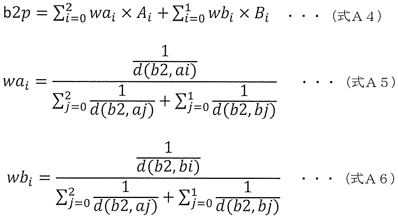
[0485] また、 三次元データ符号化装置は、 三次元点の属性情報の値と、 周囲点か ら生成した予測値との差分値 (予測残差) を算出し、 算出した予測残差を量 子化してもよい。 例えば、 三次元データ符号化装置は、 予測残差を量子化ス ケール (量子化ステップとも呼ぶ) で除算することで量子化を行う。 この場 合、 量子化スケールが小さいほど量子化によって発生しうる誤差 (量子化誤 差) が小さくなる。 逆に童子化スケ _ルが大きいほど童子化誤差は大きくな る。
[0486] なお、 三次元データ符号化装置は、 使用する量子化スケールを 1_〇 0毎に 変えてもよい。 例えば、 三次元データ符号化装置は、 上位層ほど量子化スケ
_ルを小さく し、 下位層ほど量子化スケ _ルを大きくする。 上位層に属する 三次元点の属性情報の値は、 下位層に属する三次元点の属性情報の予測値と して使用される可能性があるため、 上位層の量子化スケールを小さく して上 位層で発生しうる量子化誤差を抑え、 予測値の精度を高めることで符号化効 率を向上できる。 なお、 三次元データ符号化装置は、 L o D毎に使用する量 子化スケールをヘッダ等に付加してもよい。 これにより、 三次元データ復号 装置は、 正しく量子化スケールを復号できるので、 ビッ トストリームを適切 に復号できる。
[0487] また、 三次元データ符号化装置は、 量子化後の予測残差である符号付整数 値 (符号付量子化値) を符号なし整数値 (符号なし量子化値) に変換しても よい。 これにより予測残差をエントロピー符号化する場合に、 負の整数の発 生を考慮する必要がなくなる。 なお、 三次元データ符号化装置は、 必ずしも 符号付整数値を符号なし整数値に変換する必要はなく、 例えば符号ビッ トを 別途エントロピー符号化してもよい。
[0488] 予測残差は、 元の値から予測値を減算することにより算出される。 例えば 、 点 a 2の予測残差 a 2 「は、 (式 A 7) に示すように、 点 a 2の属性情報 の値 A 2から、 点 a 2の予測値 a 2 pを減算することで算出される。 点 b 2の 予測残差 b 2 「は、 (式 A 8) に示すように、 点 b 2の属性情報の値 B2から 、 点 b 2の予測値 b 2 pを減算することで算出される。
[0489] a 2 r=A2— a 2 p (式 A 7)
[0490] b 2 r = B2- b 2 p (式 A 8)
[0491] また、 予測残差は、 Q S (量子化ステップ (Q u a n t i z a t i o n
S t e p) ) で除算されることで量子化される。 例えば、 点 a 2の量子化値 a 2 qは、 (式 A9) により算出される。 点 b 2の量子化値 b 2 qは、 (式 A 1 0) により算出される。 ここで、 QS_L〇 DOは、 L o DO用の QS であり、 QS L o D 1は、 L o D 1用の QSである。 つまり、 L o Dに応 じて Q Sが変更されてもよい。
[0492] a 2 q = a 2 r/Q S L o D 0 (式 A9)
[0493] b 2 q = b 2 r/Q S L o D 1 (式 A 1 0)
[0494] また、 三次元データ符号化装置は、 以下のように、 上記量子化値である符 号付整数値を符号なし整数値に変換する。 三次元データ符号化装置は、 符号 付整数値 a 2 qが 0より小さい場合、 符号なし整数値 a 2 uを一 1 _ (2X a 2 q) に設定する。 三次元データ符号化装置は、 符号付整数値 a 2 qが 0 以上の場合、 符号なし整数値 a 2 uを 2 X a 2 qに設定する。
[0495] 同様に、 三次元データ符号化装置は、 符号付整数値 b 2 qが 0より小さい 場合、 符号なし整数値 b 2 uを一 1 _ (2X b 2 q) に設定する。 三次元デ —夕符号化装置は、 符号付整数値 b 2 qが 0以上の場合、 符号なし整数値 b 2 uを 2X b 2 qに設定する。
[0496] また、 三次元データ符号化装置は、 量子化後の予測残差 (符号なし整数値 ) を、 エントロピー符号化によって符号化してもよい。 例えば符号なし整数 値を二値化したうえで、 二値の算術符号化を適用してもよい。
[0497] なお、 この場合、 三次元データ符号化装置は、 予測残差の値に応じて二値 化方法を切替えてもよい。 例えば、 三次元データ符号化装置は、 予測残差 P uが閾値 R_T Hより小さい場合は、 閾値 R_T Hを表現するために必要な 固定ビッ ト数で予測残差 p uを二値化する。 また、 三次元データ符号化装置 は、 予測残差 P uが閾値 R_T H以上の場合は、 閾値 R_T Hの二値化デー 夕と (p u— R TH) の値を指数ゴロム (E x p o n e n t i a I — Go I 〇 m b ) 等を用いて二値化する。
[0498] 例えば、 三次元データ符号化装置は、 閾値[¾_丁1~1が63であり、 予測残 差 p uが 63より小さい場合は、 予測残差 p uを 6 b i tで二値化する。 ま た、 三次元データ符号化装置は、 予測残差 p uが 63以上である場合は、 閾 値 R T Hの二値データ (1 1 1 1 1 1 ) と (p u— 63) とを指数ゴロム を用いて二値化することで算術符号化を行う。
[0499] より具体的な例では、 三次元データ符号化装置は、 予測残差 p uが 32で ある場合、 6 b i tの二値データ ( 1 00000) を生成し、 このビッ ト列 を算術符号化する。 また、 三次元データ符号化装置は、 予測残差 p uが 66
\¥02020/175588 98 卩(:171? 2020 /007869
の場合、 閾値[¾_丁 1~1の二値データ ( 1 1 1 1 1 1 ) と値 3 (66-63) を指数ゴロムで表したビッ ト列 (001 00) とを生成し、 このビッ ト列 ( 1 1 1 1 1 1 +001 00) を算術符号化する。
[0500] このように、 三次元データ符号化装置は、 予測残差の大きさに応じて二値 化の方法を切替えることで、 予測残差が大きくなった場合の二値化ビッ ト数 の急激な増加を抑えながら符号化することが可能となる。 なお、 三次元デー 夕符号化装置は、 閾値
 をビッ トストリームのヘッダ等に付加しても よい。
[0501] 例えば、 高ビッ トレートで符号化が行われる場合、 つまり、 量子化スケー ルが小さい場合、 量子化誤差が小さく予測精度が高くなり、 結果として予測 残差が大きくならない可能性がある。 よって、 この場合には、 三次元データ 符号化装置は、 閾値
 を大きく設定する。 これにより、 閾値
 の二値化データを符号化する可能性が低くなり、 符号化効率が向上する。 逆 に、 低ビッ トレートで符号化が行われる場合、 つまり、 童子化スケ _ルが大 きい場合、 量子化誤差が大きく予測精度が悪くなり、 結果として予測残差が 大きくなる可能性がある。 よって、 この場合には、 三次元データ符号化装置 は、 閾値[¾_丁 1~1を小さく設定する。 これにより、 二値化データの急激なビ ッ ト長増加を防ぐことができる。
[0502] また、 三次元データ符号化装置は、 !_〇
 を切り替え、
!_〇 0毎の閾値[¾_丁 1~1をヘッダ等に付加してもよい。 つまり、 三次元デー 夕符号化装置は、 !_〇 0毎に二値化の方法を切替えてもよい。 例えば、 上位 層では三次元点間の距離が遠いため、 予測精度が悪く結果として予測残差が 大きくなる可能性がある。 よって、 三次元データ符号化装置は、 上位層に対 しては閾値[¾_丁 1~1を小さく設定することで二値化データの急激なビッ ト長 増加を防ぐ。 また、 下位層では三次元点間の距離が近いため、 予測精度が高 く結果として予測残差が小さくなる可能性がある。 よって、 三次元データ符 号化装置は、 階層に対しては閾値[¾_丁 !!を大きく設定することで符号化効 率を向上する。
[0503] 図 5 5は、 指数ゴロム符号の一例を示す図であって、 二値化前の値 (多値 ) と、 二値化後のビッ ト (符号) との関係を示す図である。 なお、 図 5 5に 示す 0と 1 とを反転させてもよい。
[0504] また、 三次元データ符号化装置は、 予測残差の二値化データに算術符号化 を適用する。 これにより、 符号化効率を向上できる。 なお、 算術符号化の適 用時に、 二値化データのうち、 nビッ トで二値化した部分である nビッ ト符 号 (n - b i t c o d e) と、 指数ゴロムを用いて二値化した部分である 残り符号 ( r e m a i n i n g c o d e) とで、 各ビッ トの 0と 1の出現 確率の傾向は異なる可能性がある。 よって、 三次元データ符号化装置は、 n ビッ ト符号と残り符号とで、 算術符号化の適用方法を切替えてもよい。
[0505] 例えば、 三次元データ符号化装置は、 nビッ ト符号に対しては、 ビッ ト毎 に異なる符号化テーブル (確率テーブル) を用いて算術符号化を行う。 この 際、 三次元データ符号化装置は、 ビッ ト毎に使用する符号化テーブルの数を 変えてもよい。 例えば、 三次元データ符号化装置は、 nビッ ト符号の先頭ビ ッ ト b 0には 1個の符号化テーブルを用いて算術符号化を行う。 また、 三次 元データ符号化装置は、 次のビッ ト b 1 に対しては 2個の符号化テーブルを 用いる。 また、 三次元データ符号化装置は、 b Oの値 (0又は 1) に応じて ビッ ト b 1の算術符号化に用いる符号化テーブルを切替える。 同様に、 三次 元データ符号化装置は、 更に次のビッ ト b 2に対しては 4個の符号化テーブ ルを用いる。 また、 三次元データ符号化装置は、 13〇及び6 1の値 (0〜 3 ) に応じて、 ビッ ト b 2の算術符号化に用いる符号化テーブルを切替える。
[0506] このように、 三次元データ符号化装置は、 nビッ ト符号の各ビッ ト b n _
1 を算術符号化する際に、 2 n - M固の符号化テーブルを用いる。 また、 三次元 データ符号化装置は、 b n - 1 より前のビッ トの値 (発生パターン) に応じ て、 使用する符号化テーブルを切替える。 これにより、 三次元データ符号化 装置は、 ビッ ト毎に適切な符号化テーブルを使用できるので、 符号化効率を 向上できる。
[0507] なお、 三次元データ符号化装置は、 各ビッ トで使用する符号化テーブルの
\¥02020/175588 100 卩(:171? 2020 /007869
数を削減してもよい。 例えば、 三次元データ符号化装置は、 各ビッ ト b n _
1 を算術符号化する際に、 匕 n_ 1 より前の ビッ ト (m<n_ 1) の値 ( 発生パターン) に応じて 2 個の符号化テーブルを切替えてもよい。 これによ り各ビッ トで使用する符号化テーブルの数を抑えつつ、 符号化効率を向上で きる。 なお、 三次元データ符号化装置は、 各符号化テーブルにおける 0と 1 の発生確率を、 実際に発生した二値化データの値に応じて更新してもよい。 また、 三次元データ符号化装置は、 _部のビッ トの符号化テーブルにおける 0と 1の発生確率を固定化してもよい。 これにより、 発生確率の更新回数を 抑制できるので処理量を削減できる。
[0508] 例えば、 门ビッ ト符号が匕 0匕 1 匕 2 匕 n - 1である場合、 匕 0用の符 号化テーブルは 1個 (〇丁匕〇) である。 匕 1用の符号化テーブルは 2個 ( 〇丁匕 1 0、 〇丁匕 1 1) である。 また、 匕 0の値 (0〜 1) に応じて使用 する符号化テーブルが切替えられる。 匕 2用の符号化テーブルは、 4個 (〇 7 b 20s 〇丁匕 2 1、 07 b 22s 07 b 23) である。 また、 匕 0及び 13 1の値 (0〜 3) に応じて使用する符号化テーブルが切替えられる。 13 n - 1用の符号化テーブルは 2 "-1個 (CT b n O、 CT b n 1、 、 07 b〇 (211-1— 1) ) である。 また、 1^ 013
 (〇〜 11-1— 1) に応じて使用する符号化テーブルを切替えられる。
[0509] なお、 三次元データ符号化装置は、 nビッ ト符号に対しては、 二値化せず に〇〜 2 1の値を設定する 3 「ソによる算術符号化 (〇1= 2 を適 用してもよい。 また、 三次元データ符号化装置が、 门ビッ ト符号を

Vで算術符号化する場合は、 三次元データ復号装置も 3
 の算術復号 により nビッ ト符号を復元してもよい。
[0510] 図 56は、 例えば、 残り符号が指数ゴロム符号の場合の処理を説明するた めの図である。 指数ゴロムを用いて二値化した部分である残り符号は、 図 5 6に示すように 「 6干 丨 X部と 3リ 干 干 丨 X部とを含む。 例えば、 三次元 データ符号化装置は、
 丨 X部とで符号化テーブル を切替える。 つまり、 三次元データ符号化装置は、
 丨 X部に含まれ
\¥02020/175588 101 卩(:171? 2020 /007869
丨 X部に含まれ
\¥02020/175588 101 卩(:171? 2020 /007869
る各ビッ トを、 「 6干 丨 X用の符号化テーブルを用いて算術符号化し、 3 リ 干 干 I X部に含まれる各ビッ トを、 3リ 干 干 I X用の符号化テーブルを用 いて算術符号化する。
[0511] なお、 三次元データ符号化装置は、 各符号化テーブルにおける 0と 1の発 生確率を、 実際に発生した二値化データの値に応じて更新してもよい。 また は、 三次元データ符号化装置は、 どちらかの符号化テーブルにおける 0と 1 の発生確率を固定化してもよい。 これにより、 発生確率の更新回数を抑制で きるので処理量を削減できる。 例えば、 三次元データ符号化装置は、 「 6 干 丨 X部に対して発生確率を更新し、 3リ チ チ 丨 X部に対して発生確率を固 定化してもよい。
[0512] また、 三次元データ符号化装置は、 量子化後の予測残差を、 逆量子化及び 再構成するこで復号し、 復号した予測残差である復号値を符号化対象の三次 元点以降の予測に利用する。 具体的には、 三次元データ符号化装置は、 量子 化後の予測残差 (量子化値) に量子化スケールを乗算することで逆量子化値 を算出し、 逆量子化値と予測値とを加算して復号値 (再構成値) を得る。
[0513] 例えば、 点 32の逆量子化値 32 丨 9は、 点 32の量子化値 329を用い て (式八 1 1) により算出される。 点匕 2の逆量子化値匕 2 丨 9は、 点匕 2 の量子化値匕 29を用いて (式八 1 2) により算出される。 ここで、 03 !_〇 00は、
 であり、 03 1_〇 01は、 !_〇 01用の〇 3である。 つまり、 !_〇 0に応じて〇 3が変更されてもよい。
[0514] 32 I 9 = 329 X03 !_〇 00 - (式八 1 1)
[0515] 62 1 9 = 629 X03 1- 001 - (式八 1 2)
[0516] 例えば、 点 32の復号値
 (式八 1 3) に示すように、 点 3
2の逆量子化値 32 丨 9に、 点 32の予測値 32 を加算することで算出さ れる。 点匕 2の復号値匕 2 「 6〇は、 (式八 1 4) に示すように、 点匕 2の 逆量子化値匕 2 丨 9に、 点匕 2の予測値匕 2 を加算することで算出される
[0517] 32 「 6〇 = 32 ^ + 32 — (式八 1 3)
[0518] b 2 r e c = b 2 i q + b 2 p (式 A 1 4)
[0519] 以下、 本実施の形態に係るビッ トストリームのシンタックス例を説明する 。 図 57は、 本実施の形態に係る属性ヘッダ (a t t r i b u t e _ h e a d e r) のシンタックス例を示す図である。 属性ヘッダは、 属性情報のへッ ダ情報である。 図 57に示すように、 属性ヘッダは、 階層数情報 (N u mL 〇 D) と、 三次元点数情報 (N u m〇 f P〇 i n t [ i ] ) と、 階層閾値 ( T h r e s L o d [ i ] ) と、 周囲点数情報 (N u mN e i g h o r P o i n t [ i ] ) と、 予測閾値 (TH d [ i ] ) と、 量子化スケール (QS [ i ] ) と、 二値化閾値 (R_TH [ i ] ) とを含む。
[0520] 階層数情報 (N u mL o D) は、 用いられる L〇 Dの階層数を示す。
[0521] 三次元点数情報 (N u m〇 f P〇 i n t [ i ] ) は、 階層 i に属する三次 元点の数を示す。 なお、 三次元データ符号化装置は、 三次元点の総数を示す 三次元点総数情報 (A l I N u mO f P o i n t) を別のヘッダに付加して もよい。 この場合、 三次元データ符号化装置は、 最下層に属する三次元点の 数を示す N u mO f P o i n t [N u mL o D— 1 ] をへッダに付加しなく てもよい。 この場合、 三次元データ復号装置は、 (式 A 1 5) により N u m 〇 f P o i n t [N u mL o D- 1 ] を算出できる。 これにより、 ヘッダの 符号量を削減できる。
[0522] [数 4]
NumLoD~2
NumOfPoint[NumLoD— 1] = AllNumO f Point- ) NumOf Point [j]
;'=〇
. . · (式 A 15)
[0523] 階層閾値 (T h r e s _ L o d [ i ] ) は、 階層 iの設定に用いられる閾 値である。 三次元データ符号化装置及び三次元データ復号装置は、 L o D i 内の各点の間の距離が閾値 T h r e s L o D [ i ] より大きくなるように L o D i を構成する。 また、 三次元データ符号化装置は、 T h r e s L o d [N u mL o D— 1 ] (最下層) の値をヘッダに付加しなくてもよい。 こ の場合、 三次元データ復号装置は、 T h r e s L o d [N u mL o D- 1
\¥02020/175588 103 卩(:171? 2020 /007869
] の値を〇と推定する。 これによりヘッダの符号量を削減できる。
[0524] 周囲点数情報 (1\1リ 111 6 丨 911〇 「?〇 丨 11 1 [丨] ) は、 階層丨 に属 する三次元点の予測値の生成に用いる周囲の点数の上限値を示す。 三次元デ —夕符号化装置は、 周囲の点数
 [ I] に満たない場合 (1\/1< リ〇1 6 丨 91"1〇 「?〇 丨 11 1 [丨] ) は、 IV!個の 周囲の点数を用いて予測値を算出してもよい。 また、 三次元データ符号化装 置は、
 [ I] の値を分ける必要 がない場合は、 全ての 1_〇 0で使用される 1個の周囲点数情報


[0525] 予測閾値 (丁 1~1 [丨] ) は、 階層丨 にて符号化又は復号対象の対象三次 元点の予測に用いる周囲の三次元点と対象三次元点との距離の上限値を示す 。 三次元データ符号化装置及び三次元データ復号装置は、 対象三次元点から の距離が丁1~1 [ I] より離れている三次元点を予測に用いない。 なお、 三 次元データ符号化装置は、 各 L o DでTH d [ I] の値を分ける必要がない 場合は、 全ての !_〇 0で使用される 1個の予測閾値 (丁 1~1 ) をヘッダに付 加してもよい。
[0526] 量子化スケール (03 [丨] ) は、 階層丨の量子化及び逆量子化で用いら れる量子化スケ _ルを示す。
[0527] 二値化閾値 ([¾_丁1~1 [丨] ) は、 階層丨 に属する三次元点の予測残差の 二値化方法を切替えるための閾値である。 例えば、 三次元データ符号化装置 は、 予測残差が閾値[¾_丁1~1より小さい場合は、 固定ビッ ト数で予測残差 リを二値化し、 予測残差が閾値[¾_丁 1~1以上の場合は、 閾値[¾_丁 1~1の二値 化データと ( リー[¾_丁1~1) の値を指数ゴロムを用いて二値化する。 なお 、 各 L o DでR_TH [ I] の値を切替える必要がない場合は、 三次元デー 夕符号化装置は、 全ての !_〇 0で使用される 1個の二値化閾値 ([¾_丁1~1) をヘッダに付加してもよい。
[0528] なお、
 [丨] は n b 丨 1:で表せる最大値であってもよい。 例えば
 。 また、 三次元データ符号化装置は、 二値化閾値として n b i tで表せる最 大値を符号化する代わりに、 ビッ ト数を符号化してもよい。 例えば、 三次元 データ符号化装置は、 R T H [ i ] =63の場合は値 6を、 R_T H [ i ] =255の場合は値 8をヘッダに付加してもよい。 また、 三次元データ符 号化装置は、 R_TH [ i ] を表すビッ ト数の最小値 (最小ビッ ト数) を定 義し、 最小値からの相対ビッ ト数をヘッダに付加してもよい。 例えば、 三次 元データ符号化装置は、 R TH [ i ] =63で最小ビッ ト数が 6の場合は 値 0をへッダに付加し、 R T H [ i ] =255で最小ビッ ト数が 6の場合 は値 2をヘッダに付加してもよい。
[0529] また、 三次元データ符号化装置は、 N u mL o D、 T h r e s_L o d [ i ] 、 N u mN e i g h b o r P o i n t [ i ] 、 TH d [ i ] 、 Q S [ i ] 及び R_TH [ i ] の少なくとも一つをエントロピー符号化してヘッダに 付加してもよい。 例えば、 三次元データ符号化装置は、 各値を二値化して算 術符号化してもよい。 また、 三次元データ符号化装置は、 処理量を抑えるた めに各値を固定長で符号化してもよい。
[0530] また、 三次元データ符号化装置は、 N u mL o D、 T h r e s_L o d [ i ] 、 N u mN e i g h b o r P o i n t [ i ] 、 TH d [ i ] 、 Q S [ i ] 、 及び R_TH [ i ] の少なくとも一つをヘッダに付加しなくてもよい。 例えば、 これらのうちの少なくとも一つの値が、 規格等の p r o f i 丨 e又 は丨 e V e 丨等で規定されてもよい。 これによりヘッダのビッ ト量を削減す ることができる。
[0531] 図 58は、 本実施の形態に係る属性データ (a t t r i b u t e d a t a) のシンタックス例を示す図である。 この属性データは、 複数の三次元点 の属性情報の符号化データを含む。 図 58に示すように属性データは、 nビ ッ ト符号 (n— b i t c o d e) と、 残り符号 ( r e m a i n i n g c 〇 d e ) とを含む。
[0532] nビッ ト符号は (n _ b i t c o d e) は、 属性情報の値の予測残差の 符号化データ又はその一部である。 nビッ ト符号のビッ ト長は R TH [ i
] の値に依存する。 例えば R_TH [ i] の示す値が 63の場合、 nビッ ト 符号は 6 b i tであり、 R T H [ i] の示す値が 255の場合、 nビッ ト 符号は 8 b i tである。
[0533] 残り符号 ( r e m a i n i n g c o d e) は、 属性情報の値の予測残差 の符号化データのうち、 指数ゴロムで符号化された符号化データである。 こ の残り符号は、 nビッ ト符号が R_TH [ i] と同じ場合に符号化又は復号 される。 また、 三次元データ復号装置は、 nビッ ト符号の値と残り符号の値 を加算して予測残差を復号する。 なお、 nビッ ト符号が R_TH [ i] と同 じ値でない場合は、 残り符号は符号化又は復号されなくてもよい。
[0534] 以下、 三次元データ符号化装置における処理の流れを説明する。 図 59は 、 三次元データ符号化装置による三次元データ符号化処理のフローチヤート である。
[0535] まず、 三次元データ符号化装置は、 位置情報 (g e ome t r y) を符号 化する (S 3001 ) 。 例えば、 三次元データ符号化は、 8分木表現を用い て符号化を行う。
[0536] 三次元データ符号化装置は、 位置情報の符号化後に、 量子化等によって三 次元点の位置が変化した場合に、 変化後の三次元点に元の三次元点の属性情 報を再割り当てする (S 3002) 。 例えば、 三次元データ符号化装置は、 位置の変化量に応じて属性情報の値を補間することで再割り当てを行う。 例 えば、 三次元データ符号化装置は、 変化後の三次元位置に近い変化前の三次 元点を N個検出し、 N個の三次元点の属性情報の値を重み付け平均する。 例 えば、 三次元データ符号化装置は、 重み付け平均において、 変化後の三次元 位置から各 N個の三次元までの距離に基づいて重みを決定する。 そして、 三 次元データ符号化装置は、 重み付け平均により得られた値を変化後の三次元 点の属性情報の値に決定する。 また、 三次元データ符号化装置は、 量子化等 によって 2個以上の三次元点が同一の三次元位置に変化した場合は、 その変 化後の三次元点の属性情報の値として、 変化前の 2個以上の三次元点の属性 情報の平均値を割当ててもよい。
\¥0 2020/175588 106 卩(:171? 2020 /007869
[0537] 次に、 三次元データ符号化装置は、 再割り当て後の属性情報 (八 1 1 「 丨 匕リ 1
 を符号化する (3 3 0 0 3) 。 例えば、 三次元データ符号化装置 は、 複数種類の属性情報を符号化する場合は、 複数種類の属性情報を順に符 号化してもよい。 例えば、 三次元データ符号化装置は、 属性情報として、 色 と反射率とを符号化する場合は、 色の符号化結果の後に反射率の符号化結果 を付加したビッ トストリームを生成してもよい。 なお、 ビッ トストリームに 付加される属性情報の複数の符号化結果の順番は、 この順に限らず、 どのよ うな順番でもよい。
[0538] また、 三次元データ符号化装置は、 ビッ トストリーム内の各属性情報の符 号化データ開始場所を示す情報をへッダ等に付加してもよい。 これにより、 三次元データ復号装置は、 復号が必要な属性情報を選択的に復号できるので 、 復号が不必要な属性情報の復号処理を省略できる。 よって、 三次元データ 復号装置の処理量を削減できる。 また、 三次元データ符号化装置は、 複数種 類の属性情報を並列に符号化し、 符号化結果を 1つのビッ トストリームに統 合してもよい。 これにより、 三次元データ符号化装置は、 高速に複数種類の 属性情報を符号化できる。
[0539] 図 6 0は、 属性情報符号化処理 (3 3 0 0 3) のフローチヤートである。
まず、 三次元データ符号化装置は、 !_〇 0を設定する (3 3 0 1 1) 。 つま り、 三次元データ符号化装置は、 各三次元点を複数の !_〇 0のいずれかに割 り当てる。
[0540] 次に、 三次元データ符号化装置は、 !_〇 0単位のループを開始する (3 3
0 1 2) 。 つまり、 三次元データ符号化装置は、 !_〇 0毎にステップ3 3 0 1 3 ~ 3 3 0 2 1の処理を繰り返し行う。
[0541 ] 次に、 三次元データ符号化装置は、 三次元点単位のループを開始する (3
3 0 1 3) 。 つまり、 三次元データ符号化装置は、 三次元点毎にステップ 3 3 0 1 4 ~ 3 3 0 2 0の処理を繰り返し行う。
[0542] まず、 三次元データ符号化装置は、 処理対象の対象三次元点の予測値の算 出に用いる、 対象三次元点の周囲に存在する三次元点である複数の周囲点を
\¥0 2020/175588 107 卩(:171? 2020 /007869
探索する (3 3 0 1 4) 。 次に、 三次元データ符号化装置は、 複数の周囲点 の属性情報の値の重み付け平均を算出し、 得られた値を予測値 に設定する (3 3 0 1 5) 。 次に、 三次元データ符号化装置は、 対象三次元点の属性情 報と予測値との差分である予測残差を算出する (3 3 0 1 6) 。 次に、 三次 元データ符号化装置は、 予測残差を量子化することで量子化値を算出する ( 3 3 0 1 7) 。 次に、 三次元データ符号化装置は、 量子化値を算術符号化す る (3 3 0 1 8) 。
[0543] また、 三次元データ符号化装置は、 量子化値を逆量子化することで逆量子 化値を算出する (3 3 0 1 9) 。 次に、 三次元データ符号化装置は、 逆量子 化値に予測値を加算することで復号値を生成する (3 3 0 2 0) 。 次に、 三 次元データ符号化装置は、 三次元点単位のループを終了する (3 3 0 2 1)
。 また、 三次元データ符号化装置は、 !_〇 0単位のループを終了する (3 3 〇 2 2) 。
[0544] 以下、 上記の三次元データ符号化装置により生成されたビッ トストリーム を復号する三次元データ復号装置における三次元データ復号処理について説 明する。
[0545] 三次元データ復号装置は、 三次元データ符号化装置によって生成されたビ ッ トストリーム内の属性情報の二値化データを、 三次元データ符号化装置と 同様の方法で算術復号することで、 復号された二値化データを生成する。 な お、 三次元データ符号化装置において、 1·!ビッ トで二値化した部分 (11ビッ 卜符号) と、 指数ゴロムを用いて二値化した部分 (残り符号) とで算術符号 化の適用方法を切替えた場合は、 三次元データ復号装置は、 算術復号適用時 に、 それに合わせて復号を行う。
[0546] 例えば、 三次元データ復号装置は、 nビッ ト符号の算術復号方法において 、 ビッ ト毎に異なる符号化テーブル (復号テーブル) を用いて算術復号を行 う。 この際、 三次元データ復号装置は、 ビッ ト毎に使用する符号化テーブル の数を変えてもよい。 例えば、 门ビッ ト符号の先頭ビッ ト匕 0には 1個の符 号化テーブルを用いて算術復号を行う。 また、 三次元データ復号装置は、 次
\¥0 2020/175588 108 卩(:171? 2020 /007869
のビッ ト匕 1 に対しては 2個の符号化テーブルを用いる。 また、 三次元デー 夕復号装置は、 匕〇の値 (0又は 1) に応じてビッ ト匕 1の算術復号に用い る符号化テーブルを切替える。 同様に、 三次元データ復号装置は、 更に次の ビッ ト匕 2に対しては 4個の符号化テーブルを用いる。 また、 三次元データ 復号装置は、 匕〇及び の値 (0〜 3) に応じて、 ビッ ト匕 2の算術復号 に用いる符号化テーブルを切替える。
[0547] このように、 三次元データ復号装置は、 门ビッ ト符号の各ビッ ト匕 n _ 1 を算術復号する際に、 2 " 個の符号化テーブルを用いる。 また、 三次元デー 夕復号装置は、 匕 n _ 1 より前のビッ トの値 (発生パターン) に応じて、 使 用する符号化テーブルを切替える。 これにより、 三次元データ復号装置は、 ビッ ト毎に適切な符号化テーブルを使用して符号化効率を向上したビッ トス トリームを適切に復号できる。
[0548] なお、 三次元データ復号装置は、 各ビッ トで使用する符号化テーブルの数 を削減してもよい。 例えば、 三次元データ復号装置は、 各ビッ ト匕 n _ 1 を 算術復号する際に、 b n _ 1 より前の ビッ ト (m < n _ 1) の値 (発生パ ターン) に応じて 2 個の符号化テーブルを切替えてもよい。 これにより、 三 次元データ復号装置は、 各ビッ トで使用する符号化テーブルの数を抑えつつ 、 符号化効率を向上したビッ トストリームを適切に復号できる。 なお、 三次 元データ復号装置は、 各符号化テーブルにおける〇と 1の発生確率を、 実際 に発生した二値化データの値に応じて更新してもよい。 また、 三次元データ 復号装置は、 一部のビッ トの符号化テーブルにおける 0と 1の発生確率を固 定化してもよい。 これにより、 発生確率の更新回数を抑制できるので処理量 を削減できる。
[0549] 例えば、 门ビッ ト符号が匕 0匕 1 匕 2 匕 n - 1である場合、 匕 0用の符 号化テーブルは 1個 (〇丁匕〇) である。 匕 1用の符号化テーブルは 2個 ( 〇丁匕 1 0、 〇丁匕 1 1) である。 また、 匕 0の値 (0〜 1) に応じて符号 化テーブルが切替えられる。 匕 2用の符号化テーブルは 4個 (〇丁匕 2 0、 〇丁匕 2 1、 0 7 b 2 2 s 〇丁匕 2 3) である。 また、 匕 0及び匕 1の値 (
\¥0 2020/175588 109 卩(:171? 2020 /007869
〇〜 3) に応じて符号化テーブルが切替えられる。
 _ 1用の符号化テー ブルは、 2 " - 1個 (〇丁匕门〇、 〇丁匕门 1、 、 0 7 b n (2 " 一 1) ) である。 また、
 (0〜 2 " - 1 - 1) に応じて符号化テ —ブルが切替えられる。
[0550] 図 6 1は、 例えば、 残り符号が指数ゴロム符号である場合の処理を説明す るための図である。 三次元データ符号化装置が指数ゴロムを用いて二値化し て符号化した部分 (残り符号) は、 図 6 1 に示すように 「 6干 丨 X部と 3 リ 干 チ 丨 X部とを含む。 例えば、 三次元データ復号装置は、 「 6チ 丨 X部 と 3リ 干 干 丨 X部とで符号化テーブルを切替える。 つまり、 三次元データ復 号装置は、 「 6干 丨 X部に含まれる各ビッ トを、 「 6干 丨 X用の符号化 テーブルを用いて算術復号し、 3リ 干 干 丨 X部に含まれる各ビッ トを、 3リ 干 干 丨 X用の符号化テーブルを用いて算術復号する。
[0551 ] なお、 三次元データ復号装置は、 各符号化テーブルにおける 0と 1の発生 確率を、 復号時に発生した二値化データの値に応じて更新してもよい。 また は、 三次元データ復号装置は、 どちらかの符号化テーブルにおける 0と 1の 発生確率を固定化してもよい。 これにより、 発生確率の更新回数を抑制でき るので処理量を削減できる。 例えば、 三次元データ復号装置は、 「 6干 丨 X部に対して発生確率を更新し、 3リ チ チ 丨 X部に対して発生確率を固定化 してもよい。
[0552] また、 三次元データ復号装置は、 算術復号した予測残差の二値化データを 、 三次元データ符号化装置で用いられた符号化方法に合わせて多値化するこ とで量子化後の予測残差 (符号なし整数値) を復号する。 三次元データ復号 装置は、 まず nビッ ト符号の二値化データを算術復号することで復号した n ビッ ト符号の値を算出する。 次に、 三次元データ復号装置は、 〇ビッ ト符号 の値と [¾_丁 1~1の値とを比較する。
[0553] 三次元データ復号装置は、 nビッ ト符号の値と [¾_丁 1~1の値とが一致した 場合、 指数ゴロムで符号化されたビッ トが次に存在すると判定し、 指数ゴロ ムで符号化された二値化データである残り符号を算術復号する。 そして、 三
\¥0 2020/175588 1 10 卩(:171? 2020 /007869
次元データ復号装置は、 復号した残り符号から、 残り符号とその値との関係 を示す逆引きテーブルを用いて残り符号の値を算出する。 図 6 2は、 残り符 号とその値との関係を示す逆引きテーブルの例を示す図である。 次に、 三次 元データ復号装置は、 得られた残り符号の値を[¾_丁 1~1に加算することで多 値化された量子化後の予測残差を得る。
[0554] 一方、 三次元データ復号装置は、 nビッ ト符号の値と
 の値とが一 致しない ([¾_丁 1~1より値が小さい) 場合、 nビッ ト符号の値をそのまま、 多値化された量子化後の予測残差に決定する。 これにより、 三次元データ復 号装置は、 三次元データ符号化装置で予測残差の値に応じて二値化方法を切 替えて生成したビッ トストリームを適切に復号できる。
[0555] なお、 三次元データ復号装置は、 閾値[¾_丁 1~1がビッ トストリームのへッ ダ等に付加されている場合は、
 の値をヘッダから復号し、 復号 した閾値[¾_丁 1~1の値を用いて復号方法を切替えてもよい。 また、 三次元デ —夕復号装置は、 1-〇口毎に閾値[¾_丁 1~1がヘッダ等に付加されている場合 、 1_〇口毎に復号した閾値[¾_丁 1~1を用いて復号方法を切替える。
[0556] 例えば、 閾値[¾_丁 1~1が 6 3であり、 復号した门ビッ ト符号の値が 6 3で ある場合、 三次元データ復号装置は、 残り符号を指数ゴロムにより復号する ことで残り符号の値を得る。 例えば、 図 6 2に示す例では、 残り符号が 0 0 1 0 0であり、 残り符号の値として 3が得られる。 次に、 三次元データ復号 装置は、 閾値[¾_丁1~1の値6 3と、 残り符号の値 3とを加算することで予測 残差の値 6 6を得る。
[0557] また、 復号した nビッ ト符号の値が 3 2である場合、 三次元データ復号装 置は、 nビッ ト符号の値 3 2を予測残差の値に設定する。
[0558] また、 三次元データ復号装置は、 復号した量子化後の予測残差を、 例えば 、 三次元データ符号化装置における処理と逆の処理により、 符号なし整数値 から符号付整数値に変換する。 これにより、 三次元データ復号装置は、 予測 残差をエントロピー符号化する場合に、 負の整数の発生を考慮せずに生成し たビッ トストリームを適切に復号できる。 なお、 三次元データ復号装置は、
必ずしも符号なし整数値を符号付整数値に変換する必要はなく、 例えば符号 ビッ トを別途エントロピー符号化して生成されたビッ トストリームを復号す る場合は、 符号ビッ トを復号してもよい。
[0559] 三次元データ復号装置は、 符号付整数値に変換した量子化後の予測残差を 、 逆量子化及び再構成によって復号することで復号値を生成する。 また、 三 次元データ復号装置は、 生成した復号値を、 復号対象の三次元点以降の予測 に利用する。 具体的には、 三次元データ復号装置は、 量子化後の予測残差に 、 復号した量子化スケールを乗算することで逆量子化値を算出し、 逆量子化 値と予測値とを加算して復号値を得る。
[0560] 復号された符号なし整数値 (符号なし量子化値) は、 以下の処理により符 号付整数値に変換される。 三次元データ復号装置は、 復号された符号なし整 数値 a 2 uの LS B ( l e a s t s i g n i f i c a n t b i t ) が 1 である場合、 符号付整数値 a 2 qを _ ( (a 2 u + 1 ) >>1 ) に設定する 。 三次元データ復号装置は、 符号なし整数値 a 2 uの L S Bが 1でない場合 、 符号付整数値 a 2 qを (a 2 u>>1 ) に設定する。
[0561] 同様に、 三次元データ復号装置は、 復号された符号なし整数値 b 2 uの L
S Bが 1である場合、 符号付整数値 b 2 qを _ ( (b 2 u + 1 ) >>1 ) に 設定する。 三次元データ復号装置は、 符号なし整数値 n 2 uの LS Bが 1で ない場合、 符号付整数値 b 2 qを (b 2 u>>1 ) に設定する。
[0562] また、 三次元データ復号装置による逆量子化及び再構成処理の詳細は、 三 次元データ符号化装置における逆量子化及び再構成処理と同様である。
[0563] 以下、 三次元データ復号装置における処理の流れを説明する。 図 63は、 三次元データ復号装置による三次元データ復号処理のフローチヤートである 。 まず、 三次元データ復号装置は、 ビッ トストリームから位置情報 (g e o me t r y) を復号する (S 303 1 ) 。 例えば、 三次元データ復号装置は 、 8分木表現を用いて復号を行う。
[0564] 次に、 三次元データ復号装置は、 ビッ トストリームから属性情報 (A t t r i b u t e) を復号する (S 3032) 。 例えば、 三次元データ復号装置
\¥0 2020/175588 1 12 卩(:171? 2020 /007869
は、 複数種類の属性情報を復号する場合は、 複数種類の属性情報を順に復号 してもよい。 例えば、 三次元データ復号装置は、 属性情報として色と反射率 とを復号する場合は、 ビッ トストリームに付加されている順に従い、 色の符 号化結果と反射率の符号化結果とを復号する。 例えば、 ビッ トストリームに おいて、 色の符号化結果の後に反射率の符号化結果が付加されている場合、 三次元データ復号装置は、 色の符号化結果を復号し、 その後に反射率の符号 化結果を復号する。 なお、 三次元データ復号装置は、 ビッ トストリームに付 加される属性情報の符号化結果をどのような順番で復号してもよい。
[0565] また、 三次元データ復号装置は、 ビッ トストリーム内の各属性情報の符号 化データ開始場所を示す情報を、 へッダ等を復号することで取得してもよい 。 これにより、 三次元データ復号装置は、 復号が必要な属性情報を選択的に 復号できるので、 復号が不必要な属性情報の復号処理を省略できる。 よって 、 三次元データ復号装置の処理量を削減できる。 また、 三次元データ復号装 置は、 複数種類の属性情報を並列に復号し、 復号結果を 1つの三次元点群に 統合してもよい。 これにより、 三次元データ復号装置は、 高速に複数種類の 属性情報を復号できる。
[0566] 図 6 4は、 属性情報復号処理 ( 3 3 0 3 2 ) のフローチヤートである。 ま ず、 三次元データ復号装置は、 !_〇 0を設定する ( 3 3 0 4 1 ) 。 つまり、 三次元データ復号装置は、 復号された位置情報を有する複数の三次元点の各 々を複数の 1-〇 0のいずれかに割り当てる。 例えば、 この割り当て方法は、 三次元データ符号化装置で用いられた割り当て方法と同じ方法である。
[0567] 次に、 三次元データ復号装置は、 1_〇 0単位のループを開始する ( 3 3 0 4 2 ) 。 つまり、 三次元データ復号装置は、 1_〇 0毎にステップ 3 3 0 4 3
 の処理を繰り返し行う。
[0568] 次に、 三次元データ復号装置は、 三次元点単位のループを開始する ( 3 3
0 4 3 ) 。 つまり、 三次元データ復号装置は、 三次元点毎にステップ 3 3 0 4 4 ~ 3 3 0 4 8の処理を繰り返し行う。
[0569] まず、 三次元データ復号装置は、 処理対象の対象三次元点の予測値の算出
\¥0 2020/175588 1 13 卩(:171? 2020 /007869
に用いる、 対象三次元点の周囲に存在する三次元点である複数の周囲点を探 索する (3 3 0 4 4) 。 次に、 三次元データ復号装置は、 複数の周囲点の属 性情報の値の重み付け平均を算出し、 得られた値を予測値 に設定する (3 3 0 4 5) 。 なお、 これらの処理は三次元データ符号化装置における処理と 同様である。
[0570] 次に、 三次元データ復号装置は、 ビッ トストリームから量子化値を算術復 号する (3 3 0 4 6) 。 また、 三次元データ復号装置は、 復号した量子化値 を逆量子化することで逆量子化値を算出する (3 3 0 4 7) 。 次に、 三次元 データ復号装置は、 逆量子化値に予測値を加算することで復号値を生成する (3 3 0 4 8) 。 次に、 三次元データ復号装置は、 三次元点単位のループを 終了する (3 3 0 4 9) 。 また、 三次元データ復号装置は、 !_〇 0単位のル —プを終了する (3 3 0 5 0) 。
[0571 ] 次に、 本実施の形態に係る三次元データ符号化装置及び三次元データ復号 装置の構成を説明する。 図 6 5は、 本実施の形態に係る三次元データ符号化 装置 3 0 0 0の構成を示すブロック図である。 この三次元データ符号化装置 3 0 0 0は、 位置情報符号化部 3 0 0 1 と、 属性情報再割り当て部 3 0 0 2 と、 属性情報符号化部 3 0 0 3とを備える。
[0572] 属性情報符号化部 3 0 0 3は、 入力点群に含まれる複数の三次元点の位置 情報 (9 6 0 0^ 6 1 「 7) を符号化する。 属性情報再割り当て部 3 0 0 2は 、 入力点群に含まれる複数の三次元点の属性情報の値を、 位置情報の符号化 及び復号結果を用いて再割り当てする。 属性情報符号化部 3 0 0 3は、 再割 り当てされた属性情報 (3 I I 「 丨 匕リ I 6) を符号化する。 また、 三次元 データ符号化装置 3 0 0 0は、 符号化された位置情報及び符号化された属性 情報を含むビッ トストリームを生成する。
[0573] 図 6 6は、 本実施の形態に係る三次元データ復号装置 3 0 1 0の構成を示 すブロック図である。 この三次元データ復号装置 3 0 1 0は、 位置情報復号 部 3 0 1 1 と、 属性情報復号部 3 0 1 2とを含む。
[0574] 位置情報復号部 3 0 1 1は、 ビッ トストリームから複数の三次元点の位置
情報 (g e〇 m e t r y) を復号する。 属性情報復号部 301 2は、 ビッ ト ストリームから複数の三次元点の属性情報 (a t t r i b u t e) を復号す る。 また、 三次元データ復号装置 301 0は、 復号した位置情報と復号した 属性情報とを結合することで出力点群を生成する。
[0575] 以上のように、 本実施の形態に係る三次元データ符号化装置は、 図 67に 示す処理を行う。 三次元データ符号化装置は、 属性情報を有する三次元点を 符号化する。 まず、 三次元データ符号化装置は、 三次元点の属性情報の予測 値を算出する (S 306 1 ) 。 次に、 三次元データ符号化装置は、 三次元点 の属性情報と、 予測値との差分である予測残差を算出する (S 3062) 。 次に、 三次元データ符号化装置は、 予測残差を二値化することで二値データ を生成する (S 3063) 。 次に、 三次元データ符号化装置は、 二値データ を算術符号化する (S 3064) 。
[0576] これによれば、 三次元データ符号化装置は、 属性情報の予測残差を算出し 、 さらに、 当該予測残差を二値化及び算術符号化することで、 属性情報の符 号化データの符号量を削減できる。
[0577] 例えば、 算術符号化 (S 3064) では、 三次元データ符号化装置は、 二 値データのビッ ト毎に異なる符号化テーブルを用いる。 これによれば、 三次 元データ符号化装置は、 符号化効率を向上できる。
[0578] 例えば、 算術符号化 (S 3064) では、 二値データの下位ビッ トほど、 使用する符号化テーブルの数が多い。
[0579] 例えば、 算術符号化 (S 3064) では、 三次元データ符号化装置は、 二 値データに含まれる対象ビッ トの上位ビッ トの値に応じて、 対象ビッ トの算 術符号化に使用する符号化テーブルを選択する。 これによれば、 三次元デー 夕符号化装置は、 上位ビッ トの値に応じて符号化テーブルを選択できるので 符号化効率を向上できる。
[0580] 例えば、 三次元データ符号化装置は、 二値化 (S 3063) では、 予測残 差が閾値 (R_TH) より小さい場合、 固定ビッ ト数で予測残差を二値化す ることで二値データを生成し、 予測残差が閾値 (R_TH) 以上である場合
\¥0 2020/175588 1 15 卩(:171? 2020 /007869
、 閾値 ([¾_丁1~1) を示す固定ビッ ト数の第 1符号 (nビッ ト符号) と、 予 測残差から閾値 (8_丁!~1) を減算した値を指数ゴロムで二値化した第 2符 号 (残り符号) とを含む二値データを生成する。 三次元データ符号化装置は 、 算術符号化 (3 3 0 6 4) では、 第 1符号と第 2符号とに異なる算術符号 化方法を用いる。
[0581] これによれば、 三次元データ符号化装置は、 例えば、 第 1符号と第 2符号 との各々に適した算術符号化方法により第 1符号と第 2符号を算術符号化で きるので符号化効率を向上できる。
[0582] 例えば、 三次元データ符号化装置は、 予測残差を量子化し、 二値化 3
0 6 3) では、 量子化された予測残差を二値化する。 閾値 ([¾_丁1~1) は、 童子化における童子化スケ _ルに応じて変更される。 これによれば、 三次元 データ符号化装置は、 量子化スケールに応じた適切な閾値を用いることがで きるので符号化効率を向上できる。
[0583] 例えば、 第 2符号は、 「 6干 丨 X部と、 3リ 干 干 丨 X部とを含む。 三次 元データ符号化装置は、 算術符号化 (3 3 0 6 4) では、 「 6チ 丨 X部と 3リ 干 干 丨 X部とに異なる符号化テーブルを用いる。 これによれば、 三次元 データ符号化装置は、 符号化効率を向上できる。
[0584] 例えば、 三次元データ符号化装置は、 プロセッサと、 メモリとを備え、 プ ロセッサは、 メモリを用いて、 上記の処理を行う。
[0585] また、 本実施の形態に係る三次元データ復号装置は、 図 6 8に示す処理を 行う。 三次元データ復号装置は、 属性情報を有する三次元点を復号する。 ま ず、 三次元データ復号装置は、 三次元点の属性情報の予測値を算出する (3 3 0 7 1) 。 次に、 三次元データ復号装置は、 ビッ トストリームに含まれる 符号化データを算術復号することで二値データを生成する (3 3 0 7 2) 。 次に、 三次元データ復号装置は、 二値データを多値化することで予測残差を 生成する (3 3 0 7 3) 。 次に、 三次元データ復号装置は、 予測値と予測残 差とを加算することで、 三次元点の属性情報の復号値を算出する (3 3 0 7 4) 。
\¥0 2020/175588 1 16 卩(:171? 2020 /007869
[0586] これによれば、 三次元データ復号装置は、 属性情報の予測残差を算出し、 さらに、 当該予測残差を二値化及び算術符号化することで生成された属性情 報のビッ トストリームを適切に復号できる。
[0587] 例えば、 算術復号 ( 3 3 0 7 2 ) では、 三次元データ復号装置は、 二値デ —夕のビッ ト毎に異なる符号化テーブルを用いる。 これによれば、 三次元デ —夕復号装置は、 符号化効率が向上されたビッ トストリームを適切に復号で きる。
[0588] 例えば、 算術復号 ( 3 3 0 7 2 ) では、 二値データの下位ビッ トほど、 使 用する符号化テーブルの数が多い。
[0589] 例えば、 算術復号 ( 3 3 0 7 2 ) では、 三次元データ復号装置は、 二値デ —夕に含まれる対象ビッ トの上位ビッ トの値に応じて、 対象ビッ トの算術復 号に使用する符号化テーブルを選択する。 これによれば、 三次元データ復号 装置は、 符号化効率が向上されたビッ トストリームを適切に復号できる。
[0590] 例えば、 三次元データ復号装置は、 多値化 ( 3 3 0 7 3 ) では、 二値デー 夕に含まれる固定ビッ ト数の第 1符号 (门ビッ ト符号) を多値化することで 第 1の値を生成する。 三次元データ復号装置は、 第 1の値が閾値 ( [¾_丁1~1 ) より小さい場合、 第 1の値を予測残差に決定し、
 丁 ! ! ) 以上の場合、 二値データに含まれる指数ゴロム符号である第 2符号 (残 り符号) を多値化することで第 2の値を生成し、 第 1の値と第 2の値とを加 算することで予測残差を生成する。 三次元データ復号装置は、 算術復号 ( 3 3 0 7 2 ) では、 第 1符号と第 2符号とに異なる算術復号方法を用いる。
[0591 ] これによれば、 三次元データ復号装置は、 符号化効率が向上されたビッ ト ストリームを適切に復号できる。
[0592] 例えば、 三次元データ復号装置は、 予測残差を逆量子化し、 加算 ( 3 3 0
7 4 ) では、 予測値と、 逆量子化された予測残差とを加算する。 閾値 ( [¾_ 丁 1~1 ) は、 逆童子化における童子化スケールに応じて変更される。 これによ れば、 三次元データ復号装置は、 符号化効率が向上されたビッ トストリーム を適切に復号できる。
\¥0 2020/175588 1 17 卩(:171? 2020 /007869
[0593] 例えば、 第 2符号は、 「 6干 丨 X部と、 3リ 干 干 丨 X部とを含む。 三次 元データ復号装置は、 算術復号 (3 3 0 7 2) では、 「 6チ 丨 X部と 3リ 干 干 丨 X部とに異なる符号化テーブルを用いる。 これによれば、 三次元デー 夕復号装置は、 符号化効率が向上されたビッ トストリームを適切に復号でき る。
[0594] 例えば、 三次元データ復号装置は、 プロセッサと、 メモリとを備え、 プロ セッサは、 メモリを用いて、 上記の処理を行う。
[0595] (実施の形態 9)
実施の形態 8とは別の手法で予測値を生成してもよい。 以下では、 符号化 対象の三次元点を第 1三次元点と称し、 その周囲の三次元点を第 2三次元点 と称する場合がある。
[0596] 例えば、 三次元点の属性情報の予測値の生成において、 符号化対象の三次 元点の符号化済みかつ復号済みの周囲の三次元点のうち、 最も距離が近い三 次元点の属性値をそのまま予測値として生成しても構わない。 また、 予測値 の生成では、 予測モード情報 ( 「 6 IV!〇 6) を三次元点毎に付加し、 複数の予測値から 1つの予測値を選択することで予測値を生成できるように しても構わない。 つまり、 例えば、 総数 IV!の予測モードにおいて、 予測モー ド 0に平均値、 予測モード 1 に三次元点八の属性値、 へ 予測モード IV! - 1 に三次元点 の属性値を割り当て、 予測に使用した予測モードを三次元 点毎にビッ トストリームに付加することが考えられる。 このように、 周囲の 三次元点の属性情報の平均が予測値として算出される第 1予測モードを示す 第 1予測モード値は、 周囲の三次元点の属性情報そのものが予測値として算 出される第 2予測モードを示す第 2予測モード値よりも小さくてもよい。 こ こで、 予測モード 0において算出される予測値である 「平均値」 は、 符号化 対象の三次元点の周囲の三次元点の属性値の平均値である。
[0597] 図 6 9は、 実施の形態 9に係る各予測モードにおいて算出される予測値を 示すテーブルの第 1の例を示す図である。 図 7 0は、 実施の形態 9に係る予 測値に用いる属性情報の例を示す図である。 図 7 1は、 実施の形態 9に係る
\¥0 2020/175588 1 18 卩(:171? 2020 /007869
各予測モードにおいて算出される予測値を示すテーブルの第 2の例を示す図 である。
[0598] 予測モード数1\/1は、 ビッ トストリームに付加されても構わない。 また、 予 測モード数1\/1は、 ビッ トストリームに付加されずに規格の 「〇干 丨 I 6 ,
I 6 V 6 丨等で値が規定されても構わない。 また、 予測モード数1\/1は、 予測 に用いる三次元点数 1\1から算出された値が用いられても構わない。 例えば予 測モード数1\/1は、 1\/1 = + 1 により算出されても構わない。
[0599] なお、 図 6 9に示されるテーブルは、 予測に用いる三次元点数 N = 4、 か つ、 予測モード数 1\/1 = 5の場合の例である。 点匕 2の属性情報の予測値は、 点 3 0、 3 1、 3 2、 匕 1の属性情報を用いて生成され得る。 複数の予測モ -ドから 1つの予測モードを選択する場合、 点匕 2からの各点 3 0、 3 1、
3 2、 匕 1 までの距離情報を元に、 各点 3 0、 3 1、 3 2、 匕 1の属性値を 予測値として生成する予測モードを選択してもよい。 予測モードは、 符号化 対象の三次元点毎に付加される。 予測値は、 付加された予測モードに応じた 値に応じて算出される。
[0600] 図 7 1 に示されるテーブルは、 図 6 9と同様に、 予測に用いる三次元点数
N = 4、 かつ、 予測モード数 1\/1 = 5の場合の例である。 点 3 2の属性情報の 予測値は、 点 3〇、 3 1の属性情報を用いて生成され得る。 複数の予測モー ドから 1つの予測モードを選択する場合、 点 3 2のからの各店 3 0、 3 1 ま での距離情報を元に、 各点 3 0、 3 1の属性値を予測値として生成する予測 モ_ドを選択してもよい。 予測モ_ドは、 符号化対象の三次元点毎に付加さ れる。 予測値は、 付加された予測モードに応じた値に応じて算出される。
[0601 ] なお、 上記の点 3 2のように隣接点数、 つまり、 周囲の三次元点数 1\]が4 個に満たない場合、 テーブルにおいて予測値が未割当てである予測モードを 门〇 ^ V ^ \ 1 13 1 6としてもよい。
[0602] なお、 予測モードの値の割当ては、 符号化対象の三次元点からの距離順で 決定しても構わない。 例えば、 複数の予測モードを示す予測モード値は、 予 測値として用いる属性情報を有する周囲の三次元点までの符号化対象の三次
\¥0 2020/175588 1 19 卩(:171? 2020 /007869
元点からの距離が近いほど小さい。 図 6 9の例では、 点匕 1、 3 2、 3 1、
3 0の順に符号化対象の三次元点である点匕 2への距離が近いことが示され る。 例えば、 予測値の算出では、 2以上の予測モードのうちの予測モード値 が 「 1」 で示される予測モードにおいて点匕 1の属性情報を予測値として算 出し、 予測モード値が 「2」 で示される予測モードにおいて点 3 2の属性情 報を予測値として算出する。 このように、 点匕 1の属性情報を予測値として 算出する予測モードを示す予測モード値は、 点匕 2からの距離が点匕 1 より も遠い位置にある点 3 2の属性情報を予測値として算出する予測モードを示 す予測モード値よりも小さい。
[0603] これにより、 距離が近いため予測が当たりやすく選ばれやすい可能性のあ る点に小さい予測モード値を割り振ることができ、 予測モード値を符号化す るためのビッ ト数を削減することができる。 また、 符号化対象の三次元点と 同 _の I-〇口に属する三次元点に優先的に小さい予測モード値を割当てても よい。
[0604] 図 7 2は、 実施の形態 9に係る各予測モードにおいて算出される予測値を 示すテーブルの第 3の例を示す図である。 具体的には、 第 3の例は、 予測値 に用いられる属性情報が周囲の三次元点の色情報 (丫11 ) による値である 場合の例である。 このように、 予測値に用いられる属性情報は、 三次元点の 色を示す色情報であつてもよい。
[0605] 図 7 2に示されるように、 予測モード値が 「0」 で示される予測モードに おいて算出される予測値は、 丫 II V色空間を定義する丫 II Vそれぞれの成分 の平均である。 具体的には、 当該予測値は、 点匕 1、 3 2、 3 1、
 にそ れぞれ対応する丫成分の値である丫匕 1、 丫 3 2、 丫 3 1、 丫 3〇の重み付 き平均丫 3 6と、 点匕 1、 3 2 , 3 1、 3 0にそれぞれ対応する II成分の 値である
 11 3 2、 11 3 1、 II 3 0の重み付き平均 II 3 V 6と、 点匕 1、 3 2、 3 1、 3 0にそれぞれ対応する V成分の値である V匕 1、 V 3 2 、 3 1、 V 3 0の重み付き平均 V 3 V 6と、 を含む。 また、 予測モード値 が 「1」 〜 「4」 で示される予測モードにおいて算出される予測値は、 それ
\¥0 2020/175588 120 卩(:171? 2020 /007869
11 3 2、 11 3 1、 II 3 0の重み付き平均 II 3 V 6と、 点匕 1、 3 2、 3 1、 3 0にそれぞれ対応する V成分の値である V匕 1、 V 3 2 、 3 1、 V 3 0の重み付き平均 V 3 V 6と、 を含む。 また、 予測モード値 が 「1」 〜 「4」 で示される予測モードにおいて算出される予測値は、 それ
\¥0 2020/175588 120 卩(:171? 2020 /007869
それ、 周囲の三次元点匕 1、 3 2、 3 1、 3 0の色情報を含む。 色情報は、 丫成分、 リ成分および V成分の値の組み合わせで示される。
[0606] なお、 図 7 2では、 色情報は、 丫 II V色空間で定義される値で示されてい るが、 丫 II V色空間に限らずに、
 巳色空間で定義される値で示されても よいし、 他の色空間で定義される値で示されてもよい。
[0607] このように、 予測値の算出では、 予測モードの予測値として、 2以上の平 均または属性情報を算出してもよい。 また、 2以上の平均または属性情報は 、 それぞれ、 色空間を定義する 2以上の成分の値を示していてもよい。
[0608] なお、 例えば、 図 7 2のテーブルにおいて予測モード値が 「2」 で示され る予測モードが選択された場合、 符号化対象の三次元点の属性値の丫成分、 リ成分および V成分をそれぞれ予測値丫 3 2 , II a 2 , V 3 2として用いて 符号化してもよい。 この場合、 予測モード値としての 「2」 がビッ トストリ —ムに付加される。
[0609] 図 7 3は、 実施の形態 9に係る各予測モードにおいて算出される予測値を 示すテーブルの第 4の例を示す図である。 具体的には、 第 4の例は、 予測値 に用いられる属性情報が周囲の三次元点の反射率情報による値である場合の 例である。 反射率情報は、 例えば、 反射率 を示す情報である。
[0610] 図 7 3に示されるように、 予測モード値が 「0」 で示される予測モードに おいて算出される予測値は、 点 13 1、 3 2 , 3 1、 3 0にそれぞれ対応する 反射率
 の重み付き平均
 ㊀である。 ま た、 予測モード値が 「1」 〜 「4」 で示される予測モードにおいて算出され る予測値は、 それぞれ、 周囲の三次元点 13 1、 3 2 , 3 1、
 の反射率 1〇 1、
 である。
である。
[061 1 ] なお、 例えば、 図 7 3のテーブルにおいて予測モード値が 「3」 で示され る予測モードが選択された場合、 符号化対象の三次元点の属性値の反射率を 予測値 8 3 1 として用いて符号化してもよい。 この場合、 予測モード値とし ての 「3」 がビッ トストリームに付加される。
[0612] 図 7 2および図 7 3で示されるように、 属性情報は、 第 1属性情報と、 第
1属性情報とは異なる種類の第 2属性情報とを含んでいてもよい。 第 1属性 情報は、 例えば、 色情報である。 第 2属性情報は、 例えば、 反射率情報であ る。 予測値の算出では、 第 1属性情報を用いて第 1予測値を算出し、 かつ、 第 2属性情報を用いて第 2予測値を算出してもよい。
[0613] (実施の形態 1 0)
以下、 三次元点の属性情報を符号化する別の方法として、 RAHT (R e g i o n Ad a p t i v e H i e r a r c h i c a l i r a n s r o r m) を用いた方法を説明する。 図 74は、 R A H Tを用いた属性情報の符 号化を説明するための図である。
[0614] まず、 三次元データ符号化装置は、 三次元点の位置情報に基づきモートン 符号 (Mo r t o n c o d e) を生成し、 モートン符号順に三次元点の属 性情報をソートする。 例えば、 三次元データ符号化装置は、 モートン符号の 昇順にソートを行ってもよい。 なお、 ソート順はモートン符号順に限らず、 他の順序が用いられてもよい。
[0615] 次に、 三次元データ符号化装置は、 モートン符号順で隣り合う 2つの三次 元点の属性情報に対し、 H a a r変換を適用することで、 階層 Lの高周波成 分と低周波成分を生成する。 例えば、 三次元データ符号化装置は、 2X2行 列の H a a r変換を用いてもよい。 生成された局周波成分は階層 Lの局周波 成分として符号化係数に含められ、 生成された低周波成分は階層 Lの上位階 層 L + 1の入力値として用いられる。
[0616] 三次元データ符号化装置は、 階層 Lの属性情報を用いて階層 Lの高周波成 分を生成後、 引き続き階層 L+ 1の処理を行う。 階層 L+ 1の処理では、 三 次元データ符号化装置は、 階層 Lの属性情報の H a a r変換によって得られ た 2つの低周波成分に H a a r変換を適用することで階層 L + 1の高周波成 分と低周波成分を生成する。 生成された高周波成分は階層 L+ 1の高周波成 分として符号化係数に含められ、 生成された低周波成分は階層 L+ 1の上位 階層 L + 2の入力値として用いられる。
[0617] 三次元データ符号化装置は、 このような階層処理を繰返し、 階層に入力さ
\¥0 2020/175588 122 卩(:171? 2020 /007869
れる低周波成分が 1個になった時点で、 最上位階層 !_ 3 Xに到達したと判 定する。 三次元データ符号化装置は、 階層 1- 01 8 Xに入力された階層 !_ 01 8 X— 1の低周波成分を符号化係数に含める。 そして、 符号化係数に含まれる 低周波成分又は高周波成分の値を量子化し、 エントロピー符号化等を用いて 符号化する。
[0618] なお、 三次元データ符号化装置は、 1~1 3 3 「変換適用時に隣り合う 2つの 三次元点として 1つの三次元点のみが存在する場合は、 存在する 1つの三次 元点の属性情報の値を上位階層の入力値として用いてもよい。
[0619] このように、 三次元データ符号化装置は、 入力された属性情報に対して階 層的に
 「変換を適用し、 属性情報の高周波成分と低周波成分を生成し 、 後述する量子化等を適用して符号化を行う。 これにより、 符号化効率を向 上できる。
[0620] 属性情報が !\1次元である場合、 三次元データ符号化装置は、 次元毎に独立 変換を適用し、 それぞれの符号化係数を算出してもよい。 例えば 、 属性情報が色情報 (?¾〇巳又は丫11 等) である場合、 三次元データ符号 化装置は、 成分毎に
 「変換を適用し、 それぞれの符号化係数を算出す る。
[0621 ] 三次元データ符号化装置は、 階層!-、 1_ + 1、 、 階層
 の順に 1~1
3 3 「変換を適用してもよい。 階層!- 3 Xに近づくほど入力された属性情 報の低周波成分を多く含む符号化係数が生成される。
[0622] 図 7 4に示す 〇及び 1は、 各三次元点に割当てられる重みである。 例 えば、 三次元データ符号化装置は、 !~1 3 3 「変換を適用する隣り合う 2つの 三次元点間の距離情報等に基づき重みを算出してもよい。 例えば、 三次元デ —夕符号化装置は、 距離が近いほど重みを大きくすることで符号化効率を向 上してもよい。 なお、 三次元データ符号化装置は、 この重みを別の手法によ り算出してもよいし、 重みを用いなくてもよい。
[0623] 図 7 4に示す例では、 入力属性情報は、 3 0 , 3 1、 3 2 , 3 3、

び 3 5である。 また、 !~1 3 3 「変換後の符号化係数のうち、 J a ^ . 丁 3 5
、 T b 1、 T b 3、 T c 1、 d 0が符号化される。 他の符号化係数 (b 0、 b 2、 c O等) は中間値であり、 符号化されない。
[0624] 具体的には、 図 74に示す例では、 a Oと a 1 とに H a a r変換が行われ ることで、 高周波成分 T a 1 と、 低周波成分 b 0とが生成される。 ここで、 重み wOと w 1 とが等しい場合には、 低周波成分 b Oは、 a Oと a 1 との平 均値であり、 高周波成分 T a 1は、 a 0と a 1 との差分である。
[0625] a 2には対となる属性情報が存在しないため、 a 2がそのまま b 1 として 用いられる。 同様に、 a 3には対となる属性情報が存在しないため、 a 3が そのまま b 2として用いられる。 また、 a 4と a 5とに H a a r変換が行わ れることで、 高周波成分 T a 5と、 低周波成分 b 3とが生成される。
[0626] 階層 L + 1では、 b 0と b 1 とに H a a r変換が行われることで、 高周波 成分 T b 1 と、 低周波成分 c 0とが生成される。 同様に、 b 2と b 3とに H a a r変換が行われることで、 高周波成分 T b 3と、 低周波成分 c 1 とが生 成される。
[0627] 階層 Lm a x_ 1では、 c Oと c 1 とに H a a r変換が行われることで、 高周波成分 T c 1 と、 低周波成分 d 0とが生成される。
[0628] 三次元データ符号化装置は、 H a a r変換適用後の符号化係数を量子化し たうえで符号化してもよい。 例えば、 三次元データ符号化装置は、 符号化係 数を量子化スケール (量子化ステップ (QS (Q u a n t i z a t i o n S t e p) ) とも呼ぶ) で除算することで量子化を行う。 この場合、 量子化 スケールが小さいほど量子化によって発生しうる誤差 (量子化誤差) が小さ くなる。 逆に童子化スケ _ルが大きいほど童子化誤差は大きくなる。
[0629] なお、 三次元データ符号化装置は、 量子化スケールの値を階層毎に変えて もよい。 図 75は、 階層毎に量子化スケールを設定する例を示す図である。 例えば、 三次元データ符号化装置は、 上位層ほど量子化スケールを小さく し 、 下位層ほど量子化スケールを大きくする。 上位層に属する三次元点の符号 化係数は、 下位層よりも低周波成分を多く含むため、 人間の視覚特性等で重 要な成分である可能性が高い。 そのため、 上位層の量子化スケールを小さく
して上位層で発生しうる量子化誤差を抑えることで視覚的な劣化を抑え、 符 号化効率を向上できる。
[0630] なお、 三次元データ符号化装置は、 階層毎の量子化スケールをヘッダ等に 付加してもよい。 これにより、 三次元データ復号装置は、 正しく量子化スケ —ルを復号でき、 ビッ トストリームを適切に復号できる。
[0631] また、 三次元データ符号化装置は、 量子化スケールの値を、 符号化対象の 対象三次元点の重要度に応じて適応的に切替えてもよい。 例えば、 三次元デ —夕符号化装置は、 重要度が高い三次元点には小さい量子化スケールを用い 、 重要度が低い三次元点には大きい量子化スケールを用いる。 例えば、 三次 元データ符号化装置は、 H a a r変換時の重み等から重要度を算出してもよ い。 例えば、 三次元データ符号化装置は、 wOと w 1の加算値を用いて量子 化スケールを算出してもよい。 このように重要度が高い三次元点の量子化ス ケールを小さくすることで量子化誤差が小さくなり、 符号化効率を改善でき る。
[0632] また、 上位層ほど QSの値を小さく してもよい。 これにより、 上位層ほど QWの値が大きくなり、 その三次元点の量子化誤差を抑えることで予測効率 を改善できる。
[0633] ここで、 属性情報 a 1の符号化係数 T a 1の量子化後の符号化係数 T a 1 は、 T a 1 /Q S_Lで表される。 なお、 QSは全ての階層、 又は一部の 階層で同じ値であってもよい。
[0634] QW (Q u a n t i z a t i o n We i g h t ) は、 符号化対象の三次 元点の重要度を表す値である。 例えば、 QWとして、 上述した wOと w 1の 加算値が用いられてもよい。 これにより、 上位層ほど QWの値が大きくなり 、 その三次元点の量子化誤差を抑えることで予測効率を改善できる。
[0635] 例えば、 三次元データ符号化装置は、 最初に全ての三次元点の QWの値を
1で初期化し、 H a a r変換時の wO及び w 1の値を用いて各三次元点の Q Wを更新してもよい。 または、 三次元データ符号化装置は、 全ての三次元点 の QWを値 1で初期化せずに、 階層に応じて初期値を変更してもよい。 例え
\¥0 2020/175588 125 卩(:17 2020 /007869
ば、 上位層ほど〇 の初期値を大きく設定することで上位層の量子化スケー ルが小さくなる。 これにより、 上位層の予測誤差を抑えることができるので 、 下位層の予測精度を高め、 符号化効率を改善できる。 なお、 三次元データ 符号化装置は、 〇 を必ずしも用いなくてもよい。
[0636] 〇 を用いる場合、 丁 3 1の量子化値丁 3 1 9は、 (式 < 1)

2) により算出される。
[0637] [数 5]

[0638] また、 三次元データ符号化装置は、 量子化後の符号化係数 (符号なし整数 値) を、 ある順番でスキャンし、 符号化する。 例えば、 三次元データ符号化 装置は、 上位層に含まれる三次元点から順に下位層に向かって複数の三次元 点を符号化する。
[0639] 例えば、 図 7 4に示す例の場合、 三次元データ符号化装置は、 上位層 1_ 父に含まれる〇1 0 から丁〇 1 、 丁 13 1 9、 丁 6 3 、 丁 "! 、 T ^ 5 9の順で複数の三次元点を符号化する。 ここで、 下位層!-になるほど、 量 子化後の符号化係数が〇になりやすい傾向がある。 この要因として、 以下の ことなどが上げられる。
[0640] 下位層!-の符号化係数は、 上位層より高い周波数成分を示すため、 対象三 次元点によっては〇になりやすい傾向がある。 また、 上述した重要度等に応 じた量子化スケールの切り替えにより、 下位層ほど量子化スケールが大きく なり、 量子化後の符号化係数が〇になりやすい。
[0641 ] このように、 下位層になるほど、 量子化後の符号化係数が 0になりやすく 、 値〇が連続して第 1符号列に発生しやすい。 図 7 6は、 第 1符号列及び第 2符号列の例を示す図である。
[0642] 三次元データ符号化装置は、 第 1符号列で値 0が発生した回数をカウント し、 連続した値〇の代わりに、 値〇が連続して発生した回数を符号化する。 つまり、 三次元データ符号化装置は、 第 1符号列において連続する値〇の符 号化係数を〇の連続回数 (Z e r oC n t ) に置き換えることで第 2符号列 を生成する。 これにより、 量子化後の符号化係数の値〇が連続した場合に、 多数の〇を符号化するよりも〇の連続回数を符号化することで符号化効率を 向上できる。
[0643] また、 三次元データ符号化装置は、 Z e r〇 C n tの値をエントロピー符 号化してもよい。 例えば、 三次元データ符号化装置は、 符号化三次元点の総 数 Tのトランケッ トユーナリ符号 (t r u n c a t e d u n a r y c〇 d e) で Z e r oC n tの値を二値化し、 二値化後の各ビッ トを算術符号化 する。 図 77は、 符号化三次元点の総数が Tの場合のトランケッ トユーナリ 符号の例を示す図である。 この際、 三次元データ符号化装置は、 ビッ ト毎に 異なる符号化テーブルを用いることで符号化効率を向上してもよい。 例えば 、 三次元データ符号化装置は、 1 ビッ ト目には符号化テーブル 1 を用い、 2 ビッ ト目には符号化テーブル 2を用い、 それ以降のビッ トには符号化テーブ ル 3を用いる。 このように、 三次元データ符号化装置は、 ビッ ト毎に符号化 テーブルを切り替えることで符号化効率を向上できる。
[0644] また、 三次元データ符号化装置は、 Z e r oC n tを指数ゴロム (E x p o n e n t i a l -Go l om b) で二値化したうえで算術符号化してもよ い。 これにより、 Z e r〇 C n tの値が大きくなりやすい場合に、 トランケ ッ トューナリ符号による二値化算術符号化よりも効率を向上できる。 なお、 三次元データ符号化装置は、 トランケッ トューナリ符号を用いるか指数ゴロ ムを用いるかを切り替えるためのフラグをへッダに付加してもよい。 これに より、 三次元データ符号化装置は、 最適な二値化方法を選択することで符号 化効率を向上できる。 また、 三次元データ復号装置はヘッダに含まれるフラ グを参照して二値化方法を切り替えて、 ビッ トストリームを正しく復号でき る。
[0645] 三次元データ復号装置は、 復号した量子化後の符号化係数を、 三次元デー 夕符号化装置で行われた方法と逆の方法で符号なし整数値から符号付き整数 値に変換してもよい。 これにより符号化係数がエントロピー符号化される場 合に、 三次元データ復号装置は、 負の整数の発生を考慮せずに生成されたビ ッ トストリームを適切に復号できる。 なお、 三次元データ復号装置は、 符号 化係数を必ずしも符号なし整数値から符号付き整数値に変換する必要はない 。 例えば、 三次元データ復号装置は、 別途エントロピー符号化された符号化 ビッ トを含むビッ トストリームを復号する場合は、 当該符号ビッ トを復号し てもよい。
[0646] 三次元データ復号装置は、 符号付き整数値に変換した量子化後の符号化係 数を、 逆量子化、 及び逆 H a a r変換によって復号する。 また、 三次元デー 夕復号装置は、 復号後の符号化係数を、 復号対象の三次元点以降の予測に利 用する。 具体的には、 三次元データ復号装置は、 量子化後の符号化係数に復 号した量子化スケールを乗算することで逆量子化値を算出する。 次に三次元 データ復号装置は、 逆量子化値に後述する逆 H a a r変換を適用することで 復号値を得る。
[0647] 例えば、 三次元データ復号装置は、 復号された符号なし整数値を以下の方 法で符号付き整数値に変換する。 復号された符号なし整数値 a 2 uの L S B ( l e a s t s i g n i f i c a n t b i t) が 1である場合、 符号付 き整数値 T a 1 qは、 一 ( (a 2 u + 1) >>1) に設定される。 復号され た符号なし整数値 a 2 uの L S Bが 1でない場合 ( 0である場合) 、 符号付 き整数値 T a 1 qは、 (a 2 u»1) に設定される。
[0648] また、 T a 1の逆量子化値は、 T a 1 q XQS Lで表される。 ここで、
T a 1 qは、 T a 1の量子化値である。 また、 Q S_Lは階層 Lの量子化ス テツプである。
[0649] また、 QSは全ての階層、 又は一部の階層で同じ値であってもよい。 また 、 三次元データ符号化装置は、 QSを示す情報をヘッダ等に付加してもよい 。 これにより、 三次元データ復号装置は、 三次元データ符号化装置で用いら
\¥0 2020/175588 128 卩(:171? 2020 /007869
れた〇 3と同じ〇 3を用いて、 正しく逆量子化を行える。
[0650] 次に、 逆 1~1 3 3 「変換について説明する。 図 7 8は、 逆 1~1 3 3 「変換を説 明するための図である。 三次元データ復号装置は、 逆量子化後の符号化係数 に、 逆
 変換を適用することで三次元点の属性値を復号する。
[0651 ] まず、 三次元データ復号装置は、 三次元点の位置情報に基づきモートン符 号を生成し、 モートン符号順に三次元点をソートする。 例えば、 三次元デー 夕復号装置は、 モートン符号の昇順にソートを行ってよい。 なお、 ソート順 はモートン符号順に限らず、 他の順序が用いられてもよい。
[0652] 次に、 三次元データ復号装置は、 階層!- + 1の低周波成分を含む符号化係 数と階層!-の高周波成分を含む符号化係数に逆 ! ! 3 3 「変換を適用すること で、 階層!-においてモートン符号順で隣り合う三次元点の属性情報を復元す る。 例えば、 三次元データ復号装置は、 2 2行列の逆!~1 3 3 「変換を用い てもよい。 復元された階層!-の属性情報は下位階層 1の入力値として用 いられる。
[0653] 三次元データ復号装置は、 このような階層処理を繰返し、 最下層の属性情 報が全て復号されたら処理を終了する。 なお、 逆
 「変換適用時に階層 にて隣り合う 2つの三次元点として 1つの三次元点のみが存在する場 合は、 三次元データ復号装置は、 存在する 1つの三次元点の属性値に階層 !_ の符号化成分の値を代入してもよい。 これにより、 三次元データ復号装置は 、 入力された属性情報の全ての値に ! ! 3 3 「変換を適用し、 符号化効率を向 上したビッ トストリームを正しく復号できる。
[0654] 属性情報が 1\1次元である場合、 三次元データ復号装置は、 次元毎に独立に 逆 「変換を適用し、 それぞれの符号化係数を復号してもよい。 例えば 、 属性情報が色情報 (?¾〇巳又は丫11 等) である場合、 三次元データ復号 装置は、 成分毎の符号化係数に逆 1~1 3 3 「変換を適用し、 それぞれの属性値 を復号する。
[0655] 三次元データ復号装置は、 階層 1_ + 1、 、 階層!-の順に逆 1~1
8 8 「変換を適用してもよい。 また、 図 7 8に示す 0及び 1は、 各三次
元点に割当てられる重みである。 例えば、 三次元データ復号装置は、 逆 H a a r変換を適用する隣り合う 2つの三次元点間の距離情報等に基づき重みを 算出してもよい。 例えば、 三次元データ符号化装置は、 距離が近いほど重み を大きくすることで符号化効率を向上したビッ トストリームを復号してもよ い。
[0656] 図 78に示す例では、 逆量子化後の符号化係数は、 T a 1、 T a 5、 T b
1、 T b 3、 T c 1及び d 0であり、 復号値として a 0、 a 1、 a 2、 a 3 、 a 4及び a 5が得られる。
[0657] 図 79は、 属性情報 (a t t r i b u t e _ d a t a) のシンタックス例 を示す図である。 属性情報 (a t t r i b u t e _ d a t a) は、 ゼロ連続 数 (Z e r oC n t ) と、 属性次元数 (a t t r i b u t e d i me n s i 〇 n ) と、 符号化係数 (v a l u e U ] [ i ] ) とを含む。
[0658] ゼロ連続数 (Z e r oC n t ) は、 量子化後の符号化係数において値 0が 連続する回数を示す。 なお、 三次元データ符号化装置は、 Z e r〇 C n tを 二値化したうえで算術符号化してもよい。
[0659] また、 図 79に示すように、 三次元データ符号化装置は、 符号化係数が属 する階層!- (丨 a y e r L ) が、 予め定められた閾値 T H _ I a y e r以上 かどうかを判定し、 判定結果によってビッ トストリームに付加する情報を切 り替えてもよい。 例えば、 三次元データ符号化装置は、 判定結果が真であれ ば属性情報の全ての符号化係数をビッ トストリームに付加する。 また、 三次 元データ符号化装置は、 判定結果が偽であれば一部の符号化係数をビッ トス トリームに付加してもよい。
[0660] 具体的には、 三次元データ符号化装置は、 判定結果が真であれば、 色情報 の R G B又は Y U Vの三次元情報の符号化結果をビッ トストリームに付加す る。 判定結果が偽であれば、 三次元データ符号化装置は、 色情報のうち、 G 又は Yなどの一部の情報をビッ トストリームに付加し、 それ以外の成分をビ ッ トストリームに付加しなくてもよい。 このように、 三次元データ符号化装 置は、 視覚的に劣化が目立ちにくい高周波成分を示す符号化係数を含む階層
\¥0 2020/175588 130 卩(:171? 2020 /007869
(丁 1~1 _丨 3 7 6 「より小さい階層) の符号化係数の一部をビッ トストリー ムに付加しないことで、 符号化効率を向上できる。
[0661] 属性次元数 (8 1: 1: 「 I 13リ 6 _〇1
 I 0 !·!) は、 属性情報の 次元数を示す。 例えば、 属性情報が三次元点の色情報 ([¾〇巳又は丫11 な ど) である場合、 色情報は三次元であるため属性次元数は値 3に設定される 。 属性情報が反射率である場合、 反射率は一次元であるため属性次元数は値 1 に設定される。 なお、 属性次元数はビッ トストリームの属性情報のヘッダ 等に付加されてもよい。
[0662] 符号化係数 ( V 3 I 1_1 6 [」] [丨] ) は、 丨番目の三次元点の」次元番 目の属性情報の量子化後の符号化係数を示す。 例えば属性情報が色情報の場 合、 ▽ 3 丨 1_| 6 [9 9] [1] は 1 0 0番目の三次元点の二次元番目 (例え ば◦値) の符号化係数を示す。 また、 属性情報が反射率情報の場合、 V 3 I [1 1 9] [0] は 1 2 0番目の三次元点の 1次元番目 (例えば反射率
) の符号化係数を示す。
[0663] なお、 以下の条件を満たす場合、 三次元データ符号化装置は、 V 3 I リ 6 [」] [ I] から値 1 を減算し、 得られた値をエントロピー符号化してもよ い。 この場合、 三次元データ復号装置は、 エントロピー復号後の V 8 丨 リ㊀ [」] [ I] に値 1 を加算することで符号化係数を復元する。
[0664] 上記の条件は、 (1) ^ I I V \ 13リ 6 _〇1
 I 〇 1^ = 1の場 合、 又は、 (2) ^ I I V \ 13リ 6—〇1 1 〇1 6门 3 I 〇门が 1以上で、 か つ全ての次元の値が等しい場合である。 例えば、 属性情報が反射率の場合は a t t r \ 13リ 6 _〇1
 I 〇门 = 1であるため、 三次元データ符 号化装置は符号化係数から値 1 を減算して V 3 I リ 6を算出し、 算出した V 8 丨 リ㊀を符号かする。 三次元データ復号装置は復号後の V 8 丨 リ㊀に値 1 を加算して符号化係数を算出する。
[0665] より具体的には、 例えば、 反射率の符号化係数が 1 0の場合、 三次元デー 夕符号化装置は、 符号化係数の値 1 〇から値 1 を減算した値 9を符号化する 。 三次元データ復号装置は、 復号した値 9に値 1 を加算して符号化係数の値
1 0を算出する。
[0666] また、 属性情報が色の場合は a t t r i b u t e _ d i me n s i o n =
3であるため、 三次元データ符号化装置は、 例えば、 R、 G、 Bの各成分の 量子化後の符号化係数が同じ場合は、 各符号化係数から値 1 を減算し、 得ら れた値を符号化する。 三次元データ復号装置は、 復号後の値に値 1 を加算す る。 より具体的には、 例えば、 R、 G、 Bの符号化係数 = ( 1、 1、 1) の 場合は、 三次元データ符号化装置は、 (0、 0、 0) を符号化する。 三次元 データ復号装置は、 (〇、 〇、 〇) の各成分に 1 を加算して (1、 1、 1) を算出する。 また、 R、 G、 Bの符号化係数 = (2、 1、 2) の場合は、 三 次元データ符号化装置は、 (2、 1、 2) をそのまま符号化する。 三次元デ —夕復号装置は、 復号した (2、 1、 2) をそのまま符号化係数として用い る。
[0667] このように、 Z e r oC n tを設けることで、 v a 丨 u eとして全ての次 元が 0であるバターンは生成されないので、 V a I u eの値から 1 を減じた 値を符号化できる。 よって、 符号化効率を向上できる。
[0668] また、 図 79に示す V a I u e [0] [ i ] は、 i番目の三次元点の一次 元番目の属性情報の量子化後の符号化係数を示す。 図 79に示すように符号 化係数の属する階層!- ( I a y e r L) が閾値 T H _ I a y e rより小さけ れば、 一次元番目の属性情報をビッ トストリームに付加する (二次元番目以 降の属性情報をビッ トストリーム付加しない) ことで符号量を削減してもよ い。
[0669] 三次元データ符号化装置は、 a t t r i b u t e _ d i m e n s i 〇 nの 値によって Z e r o C n tの値の算出方法を切替えてもよい。 例えば、 三次 元データ符号化装置は、 a t t r i b u t e _ d i me n s i o n = 3の場 合は、 全ての成分 (次元) の符号化係数の値が 0となる回数をカウントして もよい。 図 80は、 この場合の符号化係数と Z e r oC n tの例を示す図で ある。 例えば、 図 80に示す色情報の場合、 三次元データ符号化装置は、 R 、 G、 B成分が全て 0である符号化係数が連続する数をカウントし、 カウン
\¥0 2020/175588 132 卩(:171? 2020 /007869
卜した数を 6 「〇〇 n 1:としてビッ トストリームに付加する。 これにより 、 成分毎に 6 r〇0 n Iを符号化する必要がなくなり、 オーバへッ ドを削 減できる。 よって、 符号化効率を改善できる。 なお、 三次元データ符号化装 置は、 ^ I I \· \ 13リ 6 〇1
 I 〇 が 2以上の場合でも次元毎 に ㊀ 「 0〇 1^ を算出し、 算出した ㊀ 「 0〇 1^ 1:をビッ トストリームに 付加してもよい。
[0670] 図 8 1は、 本実施の形態に係る三次元データ符号化処理のフローチヤート である。 まず、 三次元データ符号化装置は、 位置情報 (9 6 0 0^ 6 1 「 7) を符号化する (3 6 6 0 1) 。 例えば、 三次元データ符号化装置は、 8分木 表現を用いて符号化を行う。
[0671 ] 次に、 三次元データ符号化装置は、 属性情報を変換する (3 6 6 0 2) 。
例えば、 三次元データ符号化装置は、 位置情報の符号化後に、 量子化等によ って三次元点の位置が変化した場合に、 変化後の三次元点に元の三次元点の 属性情報を再割当てする。 なお、 三次元データ符号化装置は、 位置の変化量 に応じて属性情報の値を補間して再割当てを行ってもよい。 例えば、 三次元 データ符号化装置は、 変化後の三次元位置に近い変化前の三次元点を !\1個検 出し、 1\1個の三次元点の属性情報の値を、 変化後の三次元位置から各 1\1個の 三次元までの距離に基づいて重み付け平均し、 得られた値を変化後の三次元 点の属性情報の値に設定する。 また、 三次元データ符号化装置は、 量子化等 によって 2個以上の三次元点が同一の三次元位置に変化した場合は、 その変 化後の属性情報の値として、 変化前の 2個以上の三次元点における属性情報 の平均値を割当ててもよい。
[0672] 次に、 三次元データ符号化装置は、 属性情報を符号化する 6 6 0 3)
。 例えば、 三次元データ符号化装置は、 複数の属性情報を符号化する場合は 、 複数の属性情報を順に符号化してもよい。 例えば、 三次元データ符号化装 置は、 属性情報として、 色と反射率を符号化する場合は、 色の符号化結果の 後に反射率の符号化結果を付加したビッ トストリームを生成する。 なお、 ビ ッ トストリームに付加される属性情報の複数の符号化結果はどのような順番
\¥02020/175588 133 卩(:171? 2020 /007869
でもよい。
[0673] また、 三次元データ符号化装置は、 ビッ トストリーム内の各属性情報の符 号化データの開始場所を示す情報をヘッダ等に付加してもよい。 これにより 、 三次元データ復号装置は、 復号が必要な属性情報を選択的に復号できるの で、 復号が不必要な属性情報の復号処理を省略できる。 よって、 三次元デー 夕復号装置の処理量を削減できる。 また、 三次元データ符号化装置は、 複数 の属性情報を並列に符号化し、 符号化結果を 1つのビッ トストリームに統合 してもよい。 これにより、 三次元データ符号化装置は、 高速に複数の属性情 報を符号化できる。
[0674] 図 82は、 属性情報符号化処理 (36603) のフローチヤートである。
まず、 三次元データ符号化装置は、 !~133 「変換により属性情報から符号化 係数を生成する (366 1 1) 。 次に、 三次元データ符号化装置は、 符号化 係数に量子化を適用する (366 1 2) 。 次に、 三次元データ符号化装置は 、 量子化後の符号化係数を符号化することで符号化属性情報 (ビッ トストリ —ム) を生成する (366 1 3) 。
[0675] また、 三次元データ符号化装置は、 量子化後の符号化係数に逆量子化を適 用する (366 1 4) 。 次に、 三次元データ復号装置は、 逆量子化後の符号 化係数に逆
 「変換を適用することで属性情報を復号する (366 1 5 ) 。 例えば、 復号された属性情報は、 後続の符号化において参照される。
[0676] 図 83は、 符号化係数符号化処理 (366 1 3) のフローチヤートである 。 まず、 三次元データ符号化装置は、 符号化係数を符号付き整数値から符号 なし整数値に変換する (3662 1) 。 例えば、 三次元データ符号化装置は 、 符号付き整数値を下記のように符号なし整数値に変換する。 符号付き整数 値丁 3 1 9が 0より小さい場合、 符号なし整数値は、 一 1 — ( 2 X丁 3 1 9 ) に設定される。 符号付き整数値丁 3 1 9が 0以上である場合、 符号なし整 数値は、 2X13 1 9に設定される。 なお、 符号化係数が負の値にならない 場合には、 三次元データ符号化装置は、 符号化係数をそのまま符号なし整数 値として符号化してもよい。
\¥02020/175588 134 卩(:171? 2020 /007869
[0677] 全ての符号化係数を処理済みでない場合 (36622で 1\1〇) 、 三次元デ —夕符号化装置は、 処理対象の符号化係数の値がゼロであるかを判定する ( 36623) 。 処理対象の符号化係数の値がゼロである場合 (36623で 丫 63) 、 三次元データ符号化装置は、
 リメント し (36624) 、 ステップ 36622に戻る。
[0678] 処理対象の符号化係数の値がゼロでない場合 (36623で N 0) 、 三次 元データ符号化装置は、 6 r〇 0 n Iを符号化し、 Ze r oC n tを 0に リセッ トする (36625) 。 また、 三次元データ符号化装置は、 処理対象 の符号化係数を算術符号化し (36626) 、 ステップ 36622に戻る。 例えば、 三次元データ符号化装置は、 二値算術符号化を行う。 また、 三次元 データ符号化装置は、 符号化係数から値 1 を減算し、 得られた値を符号化し てもよい。
[0679] また、 ステップ 36623~36626の処理が符号化係数毎に繰り返し 行われる。 また、 全ての符号化係数を処理済みである場合 (36622で丫 63) , 三次元データ符号化装置は、 処理を終了する。
[0680] 図 84は、 本実施の形態に係る三次元データ復号処理のフローチヤートで ある。 まず、 三次元データ復号装置は、 ビッ トストリームから位置情報 (9 6〇 6 「 7) を復号する (3663 1) 。 例えば、 三次元データ復号装 置は、 8分木表現を用いて復号を行う。
[0681] 次に、 三次元データ復号装置は、 ビッ トストリームから属性情報を復号す る (36632) 。 例えば、 三次元データ復号装置は、 複数の属性情報を復 号する場合は、 複数の属性情報を順に復号してもよい。 例えば、 三次元デー 夕復号装置は、 属性情報として、 色と反射率を復号する場合は、 ビッ トスト リームに付加されている順に従い、 色の符号化結果、 及び反射率の符号化結 果を復号する。 例えば、 ビッ トストリームにおいて、 色の符号化結果の後に 、 反射率の符号化結果が付加されている場合、 三次元データ復号装置は、 色 の符号化結果を復号し、 その後に反射率の符号化結果を復号する。 なお、 三 次元データ復号装置は、 ビッ トストリームに付加される属性情報の符号化結
果をどのような順番で復号してもよい。
[0682] また、 三次元データ復号装置は、 ビッ トストリーム内の各属性情報の符号 化データの開始場所を示す情報をへッダ等を復号することで取得してもよい 。 これにより、 三次元データ復号装置は、 復号が必要な属性情報を選択的に 復号できるので、 復号が不必要な属性情報の復号処理を省略できる。 よって 、 三次元データ復号装置の処理量を削減できる。 また、 三次元データ復号装 置は、 複数の属性情報を並列に復号し、 復号結果を 1つの三次元点群に統合 してもよい。 これにより、 三次元データ復号装置は、 高速に複数の属性情報 を復号できる。
[0683] 図 85は、 属性情報復号処理 (S 6632) のフローチヤートである。 ま ず、 三次元データ復号装置は、 ビッ トストリームから符号化係数を復号する (S 664 1) 。 次に、 三次元データ復号装置は、 符号化係数に逆量子化を 適用する (S 6642) 。 次に、 三次元データ復号装置は、 逆量子化後の符 号化係数に逆 H a a r変換を適用することで属性情報を復号する (S 664 3) 。
[0684] (実施の形態 1 1)
図 86は、 本実施の形態に係る属性情報符号化部の概略構成を説明するた めの図である。 図 87は、 本実施の形態に係る属性情報復号部の概略構成を 説明するための図である。
[0685] 符号化効率を向上させるために、 PCC (P o i n t C l o u d Co m p r e s s i o n) における属性情報は、 様々な方法 (例えば、 リフティ ング、 RAHT、 または、 他の変換処理) によって変換される。 変換処理は 、 強い 「エネルギー圧縮」 の特性を持つ。 変換処理によって、 重要な信号情 報は、 低周波数成分に含まれるようになる。 また、 高周波成分は、 発生ビッ 卜数を抑制するために量子化される。
[0686] 本実施の形態では、 三次元データ符号化装置は、 さらに符号化効率を向上 するために、 つまり、 各三次元点の位置の関係性を最大にすることで、 変換 される高周波数成分を最小にするために、 入力される点群データ (以下、 単
\¥0 2020/175588 136 卩(:171? 2020 /007869
に点群ともいう) における各三次元点の順序、 より具体的には、 各三次元点 に対して変換処理を行う順序を、 位置情報を用いて変更する。
[0687] まず、 三次元データ符号化装置が備える点群再配列部 7 4 0 1は、 複数の 三次元点が所定の順序で配列された、 入力された点群データにおける各三次 元点の順序を並べ替える処理 (再配列処理 ( 6 _ 0 「〇1 6 1^ 丨 11 9) ) を 行う。 例えば、 三次元データ符号化装置に入力される点群における各三次元 点を示すデータは、 所定の順序で配列されている。 点群再配列部 7 4 0 1は 、 入力された点群における各三次元点を示すデータを、 所定の方法で並べ替 ス ·る。
[0688] 次に、 三次元データ符号化装置が備える変換部 7 4 0 2は、 再配列処理に よって並べ替えた点群に対して変換処理 (丁
 を行う。
を行う。
[0689] 次に、 三次元データ符号化装置が備える量子化部 7 4 0 3は、 量子化処理 を行う。
[0690] 次に、 三次元データ符号化装置が備えるエントロピー符号化部 7 4 0 4は 、 エントロピー符号化処理を行う。 例えば、 エントロピー符号化部 7 4 0 4 は、 符号化した点群データを含むビッ トストリーム (符号化ビッ トストリー ム) を三次元デ _夕復号装置に送信する。
[0691 ] 三次元データ復号装置が備えるエントロピー復号部 7 4 1 1は、 例えば、 三次元データ符号化装置から受信したビッ トストリームに含まれる符号化さ れた点群データに対してエントロピー復号処理を行う。
[0692] 次に、 三次元データ復号装置が備える逆量子化部 7 4 1 2は、 逆量子化処 理を行う。
[0693] 次に、 三次元データ復号装置が備える逆変換部 7 4 1 4は、 逆変換処理 (
I 门 6 「 3 6 1. 「 3 门 3 1: 0 「 111) ¾:行つ。
[0694] 次に、 三次元データ復号装置が備える点群再配列部 7 4 1 3は、 逆変換処 理が行われた点群データに対して再配列処理 (配列処理) を行う。 ここでの 再配列処理は、 三次元データ符号化装置における再配列処理とは逆の処理で ある。 これにより、 三次元データ復号装置は、 復号した点群データを配列し
\¥0 2020/175588 137 卩(:171? 2020 /007869
なおすことで、 三次元データ符号化装置に入力された点群データと同じ三次 元点の順序で配列された点群データを生成できる。 三次元データ復号装置は 、 例えば、 再配列処理を行った点群データを別の装置へ送信 (出力) する。 これにより、 当該別の装置は、 三次元データ符号化装置に入力された点群デ —夕と同じ順序に配列された点群データを取得できる。
[0695] なお、 三次元データ復号装置は、 逆変換処理を行った後に三次元データ符 号化装置と同じ方法で点群の再配列処理を行なってもよい。
[0696] 例えば、 三次元データ符号化装置は、 点群を符号化および復号した位置情 報を用いて再配列した点群の順序を示す再配列情報を生成して再配列処理を 行う。 また、 例えば、 三次元データ復号装置は、 復号した位置情報を用いて 三次元データ符号化装置と同様の方法で再配列情報を生成して再配列処理を 行ぅ。
[0697] これにより、 三次元データ復号装置は、 三次元データ符号化装置に入力さ れた点群のデータの配列 (順序) と同じ配列の点群 (点群データ) を生成し て出力できる。
[0698] なお、 三次元データ符号化装置に入力された点群と同じ配列の点群を三次 元データ復号装置が生成する必要がない場合には、 三次元データ復号装置は 、 再配列処理を省略してもよい。
[0699] これにより、 三次元データ復号装置は、 処理量を削減できる。
[0700] また、 三次元データ符号化装置は、 再配列情報をビッ トストリームに付加 してもよい。 再配列情報は、 三次元データ符号化装置に入力された際の (つ まり、 再配列する前の) 点群データにおける複数の三次元点の属性情報のデ —夕の順序を示す情報である。 また、 三次元データ復号装置は、 ビッ トスト リームから復号した再配列情報を基づいて再配列処理を行ってもよい。
[0701 ] これにより、 三次元データ復号装置は、 再配列情報を生成するための処理 量を削減できる。
[0702] なお、 点群の配列を変更する方法は、 上記に限定されない。
[0703] 図 8 8は、 本実施の形態の変形例に係る属性情報符号化部の概略構成を説
\¥0 2020/175588 138 卩(:171? 2020 /007869
明するための図である。 図 8 9は、 本実施の形態の変形例に係る属性情報復 号部の概略構成を説明するための図である。
[0704] 符号化効率を向上させるために、 <3(3における属性情報は、 様々な方法 (例えば、 リフティング、 [¾八1~1丁、 または、 他の変換処理) によって変換 される。 変換処理は、 強い 「エネルギー圧縮」 の特性を持つ。 変換処理によ って、 重要な信号情報は、 低周波数成分に含まれるようになる。 また、 高周 波成分は、 発生ビッ ト数を抑制するために量子化される。
[0705] さらに符号化効率を向上するために、 三次元データ符号化装置は、 各三次 元点の位置の関係性を最大にして変換される高周波数成分を最小にするため に、 入力される点群 (点群データ) を、 位置情報を用いて順序を変更する。
[0706] まず、 三次元データ符号化装置が備える点群属性入れ替え部 7 4 2 1は、 複数の三次元点が所定の順序で配列された、 入力された点群データ (以下、 単に点群ともいう) における各三次元点の属性情報の順序を並べ替える処理 (入れ替え処理) を行う。 なお、 入れ替え処理 (スワップ) は、 再配列処理 の一例である。 例えば、 三次元データ符号化装置に入力される点群における 各三次元点を示すデータは、 所定の順序 (例えば、 モートン符号 ( 〇 「 I 6 n 〇〇 6) の順序) で配列されている。 点群属性入れ替え部 7 4 2 1 は、 例えば、 入力された点群における各三次元点を示す点群データにおける 、 モートン符号、 位置情報等をそのままの配列として、 属性情報のみを所定 の方法で並べ替える。
[0707] 例えば、 点群属性入れ替え部 7 4 2 1は、 点群の属性情報の変換処理を行 う前に、 各三次元点に割当てられたモートン符号を変えずに、 属性情報を入 れ替える入れ替え処理を行う。
[0708] 例えば、 三次元データ符号化装置は、 それぞれが三次元点である点 、 点 巳、 点 <3に対して、 モートン符号がそれぞれ 0、 1、 2と割当てられている 場合に、 点 と点 0とが位置情報等を用いて距離が近いと判断したとき、 点 巳と点 0との属性情報を入れ替える入れ替え処理を行ってから、 点 と点巳 との属性情報を用いて 8 ! !丁等の変換処理を行う。
\¥0 2020/175588 139 卩(:171? 2020 /007869
[0709] これにより、 三次元データ符号化装置は、 変換処理を行った後の高周波数 成分の係数を小さくすることができるため、 符号化効率を向上できる。
[0710] なお、 三次元データ符号化装置は、 各三次元点をどのように入れ替えした かを示す入れ替え情報をビッ トストリームのヘッダ等に付加してもよい。
[071 1 ] これにより、 三次元データ復号装置は、 逆変換処理を行った後にビッ トス トリームのヘッダから復号した、 入れ替え情報を用いて適切な三次元点に属 性情報を再割り当てする (つまり、 再配列処理を行う) ことができる。
[0712] なお、 三次元データ符号化装置は、 入れ替え情報を、 可変長符号化等を用 いて、 ヘッダに付加してもよい。
[0713] これにより、 三次元データ符号化装置は、 ヘッダ量を削減できる。
[0714] 次に、 三次元データ符号化装置が備える変換部 7 4 2 2は、 入れ替え処理 によって並べ替えた点群に対して変換処理を行う。
[0715] 次に、 三次元データ符号化装置が備える量子化部 7 4 2 3は、 量子化処理 を行う。
[0716] 次に、 三次元データ符号化装置が備えるエントロピー符号化部 7 4 2 4は 、 エントロピー符号化処理を行う。 例えば、 エントロピー符号化部 7 4 2 4 は、 符号化した点群データを含むビッ トストリームを三次元データ復号装置 に送信する。
[0717] 三次元データ復号装置が備えるエントロピー復号部 7 4 3 1は、 例えば、 三次元データ符号化装置から受信したビッ トストリームに含まれる符号化さ れた点群データに対してエントロピー復号処理を行う。
[0718] 次に、 三次元データ復号装置が備える逆量子化部 7 4 3 2は、 逆量子化処 理を行う。
[0719] 次に、 三次元データ復号装置が備える逆変換部 7 4 3 3は、 逆変換処理を 行ぅ。
[0720] 次に、 例えば、 三次元データ復号装置が備える点群属性入れ替え部 7 4 3 4は、 逆変換処理を行われた後に、 三次元データ符号化装置と同様の方法で 属性情報を入れ替える入れ替え処理を行う。
\¥0 2020/175588 140 卩(:171? 2020 /007869
[0721 ] 例えば、 三次元データ復号装置は、 それぞれが復号した三次元点である点 八、 点巳、 点 <3に対して、 モートン符号がそれぞれ 0、 1、 2と割当てられ ている場合に、 点 と点 0とが復号した位置情報等を用いて距離が近いと判 断したとき、 点巳と点 0との復号した属性情報を入れ替える。
[0722] これにより、 三次元データ復号装置は、 各三次元に適切な属性情報が割当 たった三次元点を復号できる。 また、 三次元データ復号装置は、 三次元デ 夕符号化装置に入力された点群のデータの配列 (順序) と同じ配列の点群 ( 点群データ) を生成して出力できる。
[0723] なお、 三次元データ符号化装置に入力された点群と同じ配列の点群を三次 元データ復号装置が生成する必要がない場合には、 三次元データ復号装置は 、 入れ替え処理を省略してもよい。
[0724] これにより、 三次元データ復号装置は、 処理量を削減できる。
[0725] また、 三次元データ符号化装置は、 入れ替え情報をビッ トストリームに付 加してもよい。 また、 三次元データ復号装置は、 ビッ トストリームから復号 した入れ替え情報を基づいて入れ替え処理を行ってもよい。
[0726] これにより、 三次元データ復号装置は、 入れ替え情報を生成するための処 理量を削減できる。
[0727] 図 9 0は、 本実施の形態に係る再配列処理を説明するための図である。 具 体的には、 図 9 0の (3) は、 複数のポクセル (具体的には、 8つ) と当該 複数のボクセルのそれぞれに割り振られているモートン符号の _例を示す図 である。 また、 図 9 0の (13) は、 複数のボクセル (具体的には、 8つ) と 当該複数のボクセルのそれぞれに割り振られているモートン符号の別の _例 を示す図である。 図 9 0の (〇) は、 図 9 0の (1〇) に示す点群の配列が入 れ替えられた場合の点群の配列の一例を示す図である。
[0728] なお、 図 9 0の (3) および (匕) において、 それぞれ、 左図が複数のボ クセルであり、 右図が点群の配列を示している。 なお、 点群の配列は、 モー トン符号で示されている。
[0729] 図 9 0の (3) および (匕) に示すように、 例えば、 点群は、 変換処理が
\¥0 2020/175588 141 卩(:171? 2020 /007869
行われる前には、 配列またはモートン配列で一度配列される。 ここで、 例 えば、 図 5の (匕) においては、 三次元データ符号化装置は、 変換処理を効 果的に実行するために、 例えば、 図 5の (〇) に示すように、 モートン配列 で並べた点群を、 三次元点の位置情報に基づいてさらに並び替える再配列処 理を行う。
[0730] 図 9 0の (3) は、 モートン配列で並べられた点群の一例である。 具体的 には、 図 9 0の (3) に示す例は、 各ポクセルに 1つずつ三次元点が存在す る例である。 この場合、 例えば、 点群のモートン配列が〇、 1、 2、 3、 4 、 5、 6、 7であり、 点群は、 この順に配列されている。
[0731 ] —方、 図 9 0の (13) は、 全てのボクセルに三次元点が占有されているわ けではない場合のモートン配列である。 具体的には、 ボクセル 1 とボクセル 2とは、 三次元点に占有されていない。 この場合、 例えば、 点群のモートン 配列が 0、 3、 4、 5、 6、 7であり、 点群は、 この順に配列されている。
[0732] 三次元点の位置に関連する属性情報は、 例えば、 三次元オブジェクトの表 面から取得される。 そのため、 その表面を基準として最も近い三次元点 (最 近接三次元点) 同士は、 属性情報に高い相関がある。 つまり、 近接する三次 元点同士は、 属性情報が近い値である可能性が高い。 したがって、 三次元デ —夕符号化装置は、 変換処理の前に、 このように位置が近接する三次元点が 近づくように点群を並べ替える再配列処理を行う。 例えば、 三次元データ符 号化装置は、 図 9 0の (匕) に示す 0、 3、 4、 5、 6、 7から、 図 9 0の (〇) に示す 0、 4、 3、 5、 6、 7に点群を並べ替える。 つまり、 三次元 データ符号化装置は、 モートン符号 3の三次元点とモートン符号 4の三次元 点とのデータ (位置情報、 属性情報等) の順序を入れ替える。
[0733] なお、 本例における再配列処理とは、 例えば、 三次元点の距離情報または 位置情報等を用いて点群をモートン配列から再配列処理することで生成した 新たな点群の順序を示す再配列情報を生成することを示してもよい。
[0734] 図 9 1は、 本実施の形態に係る属性情報の変換処理の第 1例を説明するた めの図である。 図 9 1 には、 例えば、 三次元データ符号化装置が変換処理を
\¥0 2020/175588 142 卩(:17 2020 /007869
行うための階層構造を示している。
[0735] 三次元データ符号化装置は、 再配列処理を行った点群に変換処理を行う。
変換処理は、 例えば、
 (部分的に適応可能な ! ! 3 3 「変換) である
[0736] 変換処理は、 例えば、 以下の
 で表される。
[0737] [数 6]
(式 N1 1)

[0738] なお、 《と /3とは任意の数であり、 《と /3とで記載される係数 (変換係数 ) は更新され得る。 丨 は、 階層の準位を示す値である。 は、 階層ごとの三 次元点の順序を示す値である。 〇 丨、 111は、 準位 I、 111番目の三次元点の属 性情報を示す値である。
[0739] また、 準位 Iの口ーパスサブバンド (低周波数成分) は、 以下の (式 1\/1 2 ) で表される。
[0740] [数 7]

[0741 ] また、 準位 Iのハイパスサブバンド (高周波数成分) は、 以下の (式 1\/1 3 ) で表される。
[0742] [数 8]

[0743] ハイパスサブバンドは、 量子化されて、 エントロピー符号化される。 一方 、 口ーパスサブバンドは、 以下の (式 1\/1 4) のように、 次の準位に移動され る。
[0744] [数 9]
 (式1\/[ 4)
[0745] 例えば、 準位丨 = 2、 〇番目 (〇1 = 0) の口ーパスサブバンドおよびハイ パスサブバンドは、 以下の (式 1\/1 5) および (式 1\/1 6) で表される。
\¥0 2020/175588 143 卩(:171? 2020 /007869
[0746] [数 10]

[0747] 例えば、 属性情報〇 3、 0と属性情報〇 3、 1 とのように、 三次元点の位 置が近い場合、 それらが同程度の属性情報が示す値 (属性値) である可能性 が高い。 そのため、 属性情報〇 3、 0と属性情報〇 3、 1 との差分から算出 されるハイパスサブバンドの値である 1~1は、 小さくなる可能性が高い。
[0748] 図 9 2は、 本実施の形態に係る属性情報の変換処理の第 2例を説明するた めの図である。 具体的には、 図 9 2の (3) は、 再配列処理が行われる前の 点群データの配列を示す図であり、 図 9 2の (匕) は、 図 9 2の (匕) に示 す点群データに対して再配列処理が行われた後の点群データの配列を示す図 である。
[0749] 三次元データ符号化装置は、 例えば、 属性情報の符号化効率をさらに向上 するために、 三次元点の距離または位置情報に基づいて、 属性情報に再配列 処理を行う。
[0750] 例えば、 図 9 2の (3) に示すように、 4 + 1) 個の点群データがモー トン符号の小さい順に 0から门まで並べられているとする。
[0751 ] 例えば、 三次元データ符号化装置は、 三次元の距離または位置情報に基づ いて、 モートン符号 (つまり三次元点のデータ) の順序を再配列する再配列 処理を行う。
[0752] こうすることで、 例えば、 三次元データ符号化装置は、 モートン符号が 1 の三次元点とモートン符号が 2の三次元点のデータの位置を入れ替え、 かつ 、 モートン符号が 7の三次元点とモートン符号が 9の三次元点のデータの位 置を入れ替えた点群データを新たに生成する。
[0753] あるいは、 三次元データ符号化装置は、 属性情報の順序を入れ替える再配 列処理を行い、 符号化および復号するための再配列情報を付加情報 (IV!

^ として保存してもよい。
\¥0 2020/175588 144 卩(:171? 2020 /007869
[0754] 図 9 3は、 本実施の形態に係る属性情報の変換処理の第 3例を説明するた めの図である。 図 9 3の (3) は、 再配列処理が行われる前の点群データの 配列を示す図であり、 図 9 3の (1〇) は、 図 9 3の (8) に示す点群データ に対して再配列処理が行われた後の点群データの配列を示す図である。 なお 、 図 9 3は、 三次元点の距離 (距離情報) を用いて点群を再配列する例を示 す図である。 例えば、 図 9 3の (3) に示すように、 4 + 1) 個の点群デ —夕がモートン符号の小さい順に 0から まで並べられているとする。
[0755] まず、 三次元データ符号化装置は、 位置 0に位置する三次元点 (つまり、 モートン符号が〇の三次元点) を参照点として、 当該参照点に近接する 個 (本例では 1< = 5) の三次元点のうち、 最も近い三次元点 (最近接三次元点 ) を探索 (算出) する。 本例では、 位置 2に位置する三次元点が、 位置 0に 最も近い三次元点であるとする。 この場合、 例えば、 三次元データ符号化装 置は、 参照点である位置〇の隣に位置 2に位置する三次元点のデータを移動 する。
[0756] なお、 三次元データ符号化装置は、 探索範囲となる三次元点の個数を示す をビッ トストリームのヘッダに付加してもよい。
[0757] これにより、 三次元データ復号装置は、 ビッ トストリームのヘッダに含ま れる探索範囲 を復号することで、 三次元データ符号化装置と同じ探索範囲 を用いて三次元点の再配列処理を行うことができる。
[0758] 次に、 三次元データ符号化装置は、 位置 1 に位置する三次元点を参照点と して、 当該参照点に近接する 個の三次元点のうち、 最近接三次元点を探索 する。 本例では、 位置 3に位置する三次元点が、 位置 1 に最も近い三次元点 であるとする。 この場合、 例えば、 三次元データ符号化装置は、 参照点であ る位置 1の隣に位置 3に位置する三次元点のデータがあるため、 次に、 例え ば参照点を位置 3に位置する三次元点として、 参照点の最近接三次元点の探 索を続ける。
[0759] 上記のように、 三次元データ符号化装置は、 例えば、 位置 nの三次元点ま で、 参照点の設定と、 設定した当該参照点との最近接三次元点の探索を行う
\¥0 2020/175588 145 卩(:171? 2020 /007869
[0760] 図 9 4は、 本実施の形態に係る属性情報の変換処理の第 4例を説明するた めの図である。 図 9 4の (3) は、 再配列処理が行われる前の点群データの 配列を示す図であり、 図 9 4の (匕) は、 図 9 4の (3) に示す点群データ に対して再配列処理が行われた後の点群データの配列を示す図である。
[0761 ] なお、 図 9 4は、 三次元点の距離 (距離情報) を用いて点群を再配列する 例を示す図である。 例えば、 図 9 4の (3) に示すように、 (n + 1) 個の 点群データがモートン符号の小さい順に 0から まで並べられているとする
[0762] まず、 三次元データ符号化装置は、 位置 0に位置する三次元点を参照点と して、 当該参照点に近接する 1<個の三次元点のうち、 最近接三次元点を探索 する。 本例では、 位置 2 4に位置する三次元点が、 位置 0に最も近い三次元 点であるとする。
[0763] 次に、 例えば、 三次元データ符号化装置は、 位置 2 4に位置する三次元点 を参照点として、 当該参照点に近接する 個の三次元点のうち、 最近接三次 元点を探索する。 三次元データ符号化装置は、 上記の再配列処理を全ての三 次元点に対して 1つずつ実行し続ける。
[0764] なお、 三次元データ符号化装置は、 モートン符号に基づいて点群の再配列 処理を行ってもよい。 あるいは、 三次元データ符号化装置は、 三次元点の属 性情報だけに再配列処理を行い、 モートン符号の位置を維持し続けてもよい 。 また、 三次元データ符号化装置は、 再配列処理を行う前の点群の位置を示 す、 点群の入れ替え情報である入れ替えテーブル情報 (再配列テーブルとも いう) を生成してもよい。
[0765] 上記したように、 例えば、 三次元データ符号化装置は、 三次元距離を用い て点群の再配列処理を行う。 例えば、 図 9 4の (3) に示すように、 4 + 1) 個の点群データがモートン符号の小さい順に 0から まで並べられてい るとする。 例えば、 三次元データ符号化装置は、 位置〇に位置する三次元点 を参照点として、 当該参照点に近接する 個の三次元点のうち、 最近接三次
\¥0 2020/175588 146 卩(:171? 2020 /007869
元点を探索する。
[0766] 次に、 三次元データ符号化装置は、 位置 0における三次元点に対応する X
0 = ( X 0 % ソ〇、 å 0) を、 位置丨 における三次元点に対応する X 丨 = ( X I X )/ \ å 1) として表す。
[0767] 次に、 位置 0に位置する三次元点に近接する 1<個の三次元点のうち、 位置
0に位置する三次元点の最近接三次元点は、 以下の (式 IV! 7) および (式 IV! 8) に示すように、 I三次元点間のユークリツ ド距離の最小値を探索するこ とによりを得られる。
[0768] [数 1 1 ]

[0769] 最近接三次元点を決定されると、 当該最近接三次元点は、 位置丨から位置
1 に再配列される。 なお、 三次元距離を決定するために別の方法が用いられ てもよい。
[0770] 図 9 5は、 本実施の形態に係る属性情報の変換処理の第 5例を説明するた めの図である。 図 9 6は、 本実施の形態に係るボクセルの接続関係の例と各 例における法線ベクトルとを説明するための図である。
[0771 ] なお、 図 9 5および図 9 6は、 三次元点の位置情報を用いて点群を再配列 する例を示す図である。
[0772] 同じオブジェクトの表面にある近接三次元点は、 類似した属性情報を有し ている可能性があるため、 符号化効率を向上させるために変換処理の前に点 群データの配列が近くに並べ替えられる。 例えば、 近接三次元点として、 点 〇 8、
 点 0 ㊀、 点 0 1"、 および、 点 0 9を有する 参照点 (ポクセル) 0 「について考える。 法線ベクトル
[数 12]
点 0 ㊀、 点 0 1"、 および、 点 0 9を有する 参照点 (ポクセル) 0 「について考える。 法線ベクトル
[数 12]
Nr (式 M 9) のような位置情報は、 三次元点の表面を決定するために用いられる。
[0773] 例えば、 再配列処理では、 点 C a、 点 C b、 および、 点 C dは、 点 C rの 法線べクトルと同じ向きであり且つ点 C rのオブジェクトと接続されている 接続タイプを有するため、 点群データが点 C rの近くに並べ替えられる。
[0774] C rの法線ベクトル (式 M 9) は、 以下の (式 M 1 0) から算出される。
[0775] [数 13]

[0776] なお、 (式 M 1 0) における 「X」 は、 外積を示す。
[0777] また、 ポクセルは、 法線ベクトルとオブジェクトの接続タイプとを用いて グループ化されてもよい。 その場合、 例えば、 三次元点は、 当該グループ化 により生成されたグループに基づいて点群データの配列が並べ替えられる。
[0778] 図 9 6に示すように、 接続タイプには、 階段タイプ (S t a i r - I i k e) 、 凸タイプ (C o n v e x) 、 凹タイプ (C o n c a v e) 等が例示さ れる。
[0779] 例えば、 上記の接続タイプは、 再配列処理のためのグループ化に用いられ る。 例えば、 凸タイプの接続タイプの関係性を有する三次元点同士は、 同じ グループにグループ化される。 一方、 例えば、 凹タイプおよび階段タイプの 接続タイプの関係性を有する三次元点同士は、 同じグループにはグループ化 されない。 凹タイプおよび階段タイプの三次元点同士は、 異なるオブジェク 卜に属す、 または、 異なる属性情報を有する可能性が高い。 例えば、 凸タイ プと比較して、 凹タイプは、 影の影響が大きい可能性が高い。 したがって、 点群のグループ化においては、 凹タイプの接続タイプの関係性を有する三次 元点同士は、 同じグループにはグループ化されずに切り離される。
[0780] なお、 上記では、 三次元データ符号化装置が垂直ベクトル (法線ベクトル ) を算出して、 算出した法線ベクトルを再配列処理に用いる例を示したが、
\¥0 2020/175588 148 卩(:171? 2020 /007869
必ずしもこれに限らない。 例えば、 三次元データ符号化装置は、 属性情報と して法線べクトルを符号化および復号する場合には、 その属性情報の値を用 いて上記のグループ化を行い、 点群の再配列処理を行ってもよい。
[0781 ] なお、 三次元データ符号化装置は、 変換処理をする前の三次元点の再配列 情報、 または、 三次元点の属性情報の入れ替え情報は、 位置情報を符号化す る際の情報を用いて生成してもよい。 例えば、 上記したように、 三次元デー 夕符号化装置は、 位置情報の各ノードのオキュパンシー符号 (〇〇〇リ 3 n c y 0 0 0^ 6) を符号化する際に算出した隣接ノード情報を用いて再配 列情報または入れ替え情報を生成する。
[0782] 本例では、 三次元データ符号化装置は、 例えば、 モートン符号が 0のノー ドのオキュパンシー符号を符号化する際に、 モートン符号が 1のノードが占 有されておらず、 かつ、 モートン符号が 4のノードが占有されていることを 示す情報を生成している可能性がある。 そのため、 三次元データ符号化装置 は、 その情報を用いることで、 モートン符号が 0のペアとしてモートン符号 が 4を選択して変換を適用してもよい。 また、 モートン符号が 1のノードの 属性情報と、 モートン符号が 4のノードの属性情報とを入れ替えて、 モート ン符号が 0のノードとモートン符号が 1のノードとに変換処理を行ってもよ い。
[0783] このように、 三次元データ符号化装置は、 位置情報を符号化する際に生成 した情報を用いて三次元点の再配列情報または属性情報の入れ替え情報を生 成して変換処理を行ってもよい。
[0784] これによれば、 三次元データ符号化装置は、 再配列情報または入れ替え情 報を生成のための処理量を抑制しつつ、 符号化効率を向上できる。
[0785] また、 三次元データ復号装置は、 逆変換処理を行った後の三次元点の再配 列情報または三次元点の属性情報の入れ替え情報を、 位置情報を復号する際 の情報を用いて生成してもよい。
[0786] 例えば、 三次元データ復号装置は、 上記したように、 位置情報の各ノード のオキュパンシー符号を復号する際に算出した隣接ノード情報を用いて再配
\¥0 2020/175588 149 卩(:171? 2020 /007869
列情報または入れ替え情報を生成する。
[0787] また、 本例では、 三次元データ復号装置は、 モートン符号が 0のノードの オキュパンシー符号を復号する際に、 モートン符号が 1のノードが非占有で あり、 かつ、 モートン符号が 4のノードが占有であることを示す情報を生成 している可能性がある。 そのため、 三次元データ復号装置は、 その情報を用 いることで、 逆変換処理を行った後のモートン符号が 1の三次元点とモート ン符号が 4の三次元点とを入れ替えてもよい。 また、 三次元データ符号化装 置は、 モートン符号が 1のノードの属性情報とモートン符号が 4のノードの 属性情報とを逆変換した後に入れ替えてもよい。
[0788] このように、 三次元データ復号装置は、 位置情報を復号する際に生成した 情報を用いて三次元点の再配列情報または属性情報の入れ替え情報を生成し て逆変換した後に三次元点を入れ替える、 または、 属性情報を入れ替えるこ とで、 再配列情報または入れ替え情報を生成するための処理量を抑制しつつ 、 符号化効率が向上されたビッ トストリームを正しく復号できる。
[0789] 図 9 7は、 本実施の形態に係る属性情報の変換処理の第 6例を説明するた めの図である。
[0790] 三次元データ符号化装置は、 各々の層で再配列処理を行ってもよい。 ある いは、 三次元データ符号化装置は、 上層で再配列処理を行うために用いられ る三次元位置を、 下層の三次元位置に基づいて算出してもよい。
[0791 ] 例えば、 階層 2 (準位 I = 2) の各三次元点の三次元位置は、 以下の (式 IV! 1 1) 、 (式 IV! 1 2) および (式 IV! 1 3) により算出される。
[0792] [数 14]
^2,0 =( 3,〇 + 3,1)/2 (式1\/[ 1 1) 1 =( 3,2+ 3,3)/2 (式]\/[ 1 2) 2,2 =( 3,4 + 3,5)/2 (式1\/[ 1 3)
[0793] また、 例えば、 階層 1 (準位 I = 1 ) の各三次元点の三次元位置は、 以下
の (式 IV! 1 4) および (式 IV! 1 5) により算出される。
[0794] [数 15]
^1,〇 =(C2,〇+C2;I)/2 (式 M 14)
Ci,i = C22 (式 M 1 5)
[0795] 図 98は、 本実施の形態に係る属性情報の変換処理の第 7例を説明するた めの図である。 なお、 図 98に示す点群データは、 モートン符号が 5の位置 に三次元点が存在しない場合を示す。
[0796] ペアを有していない各三次元点は、 変更処理が行われている間、 他の三次 元点とマージされない。 このような三次元点においては、 再配列処理を行う ことは不要である。 例えば、 位置 0に位置する三次元点は、 有効なペアを有 し、 且つ、 最近接三次元点である位置 4に位置する三次元点は、 再配列処理 が行わる。 _方、 位置 3に位置する三次元点は、 位置 5に三次元点が存在し ないため、 有効なペアを有していない。 このような位置 3に位置する三次元 点が変換処理に用いられないように、 最近接三次元点を探索する必要がない 〇
[0797] どの三次元点が変換処理のために有効なぺアを有しているかを算出するた めに、 例えば、 以下の方法が採用される。
[0798] 準位丨 における i番目のモートン符号を M 丨, i として、
I f (M l , i » 1 ) == (M l , i + 1 >> 1 ) {
F i n d t h e n e a r e s t p o i n t t o p a i r w i t h t h e p o i n t a t M l , i .
S k i p 1 p o s i t i o n a n d m o v e t o n e x t p o i n t .
} e l s e
とする。
[0799] 例えば、 三次元データ符号化装置は、 このような条件式が成り立てば、 三 次元点の変換処理のために有効なペアを有しているため、 最近傍三次元点を
\¥0 2020/175588 151 卩(:171? 2020 /007869
探索する。 一方、 例えば、 三次元データ符号化装置は、 このような条件式が 成り立たなければ、 三次元点の変換処理のために有効なぺアを有していない ため、 最近傍三次元点を探索する必要がない。 そのため、 これによれば、 三 次元データ符号化装置は、 再配列処理を行うために、 参照点等の点に対して 最近接三次元点を探索する必要がない。 そのため、 三次元データ符号化装置 は、 すぐに次の三次元点の処理へ移行できる。
[0800] 図 9 9は、 本実施の形態に係る三次元データ符号化装置 7 4 4 0のブロッ ク図である。
[0801 ] 三次元データ符号化装置 7 4 4 0は、 位置情報符号化部 7 4 4 1 と、 属性 情報符号化部 7 4 4 2と、 付加情報符号化部 7 4 4 3と、 多重化部 (1\/1 11乂 ) 7 4 4 4と、 を備える。
[0802] 位置情報符号化部 7 4 4 1は、 三次元データ符号化装置 7 4 4 0に入力さ れた点群データにおける位置情報を符号化する。 位置情報符号化部 7 4 4 1 は、 符号化した位置情報 (符号化位置情報) を多重化部 7 4 4 4に出力する
[0803] 属性情報符号化部 7 4 4 2は、 三次元データ符号化装置 7 4 4 0に入力さ れた点群データにおける属性情報を符号化する。 属性情報符号化部 7 4 4 2 は、 符号化した属性情報 (符号化属性情報) を多重化部 7 4 4 4に出力する
[0804] 付加情報符号化部 7 4 4 3は、 三次元データ符号化装置 7 4 4 0に入力さ れた点群データにおける付加情報を符号化する。 付加情報符号化部 7 4 4 3 は、 符号化した付加情報 (符号化付加情報) を多重化部 7 4 4 4に出力する
[0805] 多重化部 7 4 4 4は、 符号化位置情報、 符号化属性情報、 および、 符号化 付加情報を含むビッ トストリームを生成して出力する。 例えば、 多重化部 7 4 4 4は、 当該ビッ トストリームを三次元データ復号装置に出力する。
[0806] 図 1 0 0は、 本実施の形態に係る属性情報符号化部 7 4 4 2のブロック図 である。
\¥0 2020/175588 152 卩(:17 2020 /007869
[0807] 属性情報符号化部 7 4 4 2は、 点群再配列部 7 4 4 2 1 と、 変換部 7 4 4
2 2と、 量子化部 7 4 4 2 3と、 エントロピー符号化部 7 4 4 2 4と、 を備 ス ·る。
[0808] 点群再配列部 7 4 4 2 1は、 三次元データ符号化装置 7 4 4 0に入力され た点群データのデータ順を再配列する再配列処理を行う。 上記したように、 点群再配列部 7 4 4 2 1は、 例えば、 位置情報に基づいて、 属性情報の順序 を再配列する。
[0809] 変換部 7 4 4 2 2は、 再配列された点群データにおける属性情報の変換処 理を行う。
[0810] 量子化部 7 4 4 2 3は、 変換処理が行われた点群データに量子化処理を行 う。
[081 1 ] エントロピー符号化部 7 4 4 2 4は、 量子化された点群データにエントロ ピー符号化処理を行う。
[0812] 図 1 0 1は、 本実施の形態に係る点群再配列部 7 4 4 2 1のブロック図で ある。
[0813] 点群再配列部 7 4 4 2 1は、 モートン配列部 7 4 4 2 1 1 と、 再配列部 7 4 4 2 1 2と、 を備える。
[0814] モートン配列部 7 4 4 2 1 1は、 入力された点群データの属性情報を、 モ —トン配列に並び替える。
[0815] 再配列部 7 4 4 2 1 2は、 モートン配列に並び替えられた点群データを、 上記したように位置情報または三次元距離などに基づいて再配列する。
[0816] 図 1 0 2は、 本実施の形態に係る三次元データ復号装置 7 4 5 0のブロッ ク図である。
[0817] 三次元データ復号装置 7 4 5 0は、 逆多重化部 (〇 6 1\/1 11乂) 7 4 5 1 と 、 位置情報復号部 7 4 5 2と、 属性情報復号部 7 4 5 3と、 付加情報復号部 7 4 5 4と、 を備える。
[0818] 逆多重化部 7 4 5 1は、 ビッ トストリームに含まれる符号化位置情報、 符 号化属性情報、 および、 符号化付加情報を分割して出力する。 具体的には、
\¥0 2020/175588 153 卩(:171? 2020 /007869
逆多重化部 7 4 5 1は、 ビッ トストリームに含まれる、 符号化位置情報を位 置情報復号部 7 4 5 2に出力し、 符号化属性情報を属性情報復号部 7 4 5 3 に出力し、 符号化付加情報を付加情報復号部 7 4 5 4に出力する。
[0819] 位置情報復号部 7 4 5 2は、 符号化位置情報を復号することで位置情報を 生成し、 生成した位置情報を出力する。
[0820] 属性情報復号部 7 4 5 3は、 符号化属性情報を復号することで属性情報を 生成し、 生成した属性情報を出力する。
[0821 ] 付加情報復号部 7 4 5 4は、 符号化付加情報を復号することで付加情報を 生成し、 生成した付加情報を出力する。
[0822] 図 1 0 3は、 本実施の形態に係る属性情報復号部 7 4 5 3のブロック図で ある。
[0823] 属性情報復号部 7 4 5 3は、 エントロピー復号部 7 4 5 3 1 と、 逆量子化 部 7 4 5 3 2と、 点群再配列部 7 4 5 3 3と、 逆変換部 7 4 5 3 4と、 を備 ス ·る。
[0824] エントロピー復号部 7 4 5 3 1は、 ビッ トストリームを可変長復号する。
例えば、 エントロピー復号部 7 4 5 3 1は、 符号化属性情報を算術復号して 二値信号を生成し、 生成した二値信号から量子化係数を生成する。
[0825] 逆量子化部 7 4 5 3 2は、 エントロピー復号部 7 4 5 3 1から入力された 量子化係数を、 ビッ トストリーム等に付加された量子化パラメータを用いて 逆量子化することで、 逆量子化係数を生成する。
[0826] 逆変換部 7 4 5 3 4は、 逆量子化部 7 4 5 3 2から入力された逆量子化係 数を逆変換する。 逆変換部 7 4 5 3 4は、 例えば、 変換部 7 4 4 2 2と逆の 処理を行う。
[0827] これにより、 三次元データ符号化装置 7 4 4 0により再配列された点群デ —夕と同じ点群データが生成される。
[0828] 点群再配列部 7 4 5 3 3は、 逆変換部 7 4 5 3 4で生成された点群データ に再配列処理を行うことにより、 点群データの属性情報を再配列する。 点群 再配列部 7 4 5 3 3は、 例えば、 点群再配列部 7 4 4 2 1 と逆の処理を行う
\¥0 2020/175588 154 卩(:171? 2020 /007869
。 これにより、 三次元データ符号化装置に入力された時点の点群データと同 じデータの順序の点群データが生成される。
[0829] 図 1 0 4は、 本実施の形態の変形例に係る三次元データ符号化装置 7 4 6
0のブロック図である。
[0830] 三次元データ符号化装置 7 4 6 0は、 位置情報符号化部 7 4 6 1 と、 属性 情報符号化部 7 4 6 2と、 付加情報符号化部 7 4 6 3と、 多重化部 7 4 6 4 と、 を備える。
[0831 ] 位置情報符号化部 7 4 6 1は、 三次元データ符号化装置 7 4 6 0に入力さ れた点群データにおける位置情報を符号化する。 位置情報符号化部 7 4 6 1 は、 符号化した位置情報 (符号化位置情報) を多重化部 7 4 6 4に出力する
[0832] 属性情報符号化部 7 4 6 2は、 三次元データ符号化装置 7 4 6 0に入力さ れた点群データにおける属性情報を符号化する。 属性情報符号化部 7 4 6 2 は、 符号化した属性情報 (符号化属性情報) を多重化部 7 4 6 4に出力する
[0833] また、 属性情報符号化部 7 4 6 2は、 属性情報を符号化する前に、 点群デ —夕におけるデータの順序を並べ替える。 そこで、 属性情報符号化部 7 4 6 2は、 並べ替える前 (再配列前) のデータの順序を示す再配列テーブル (上 記した入れ替え情報の一例) を生成し、 生成した再配列テーブルを符号化し た符号化再配列テーブルを多重化部 7 4 6 4に出力する。
[0834] 付加情報符号化部 7 4 6 3は、 三次元データ符号化装置 7 4 6 0に入力さ れた点群データにおける付加情報を符号化する。 付加情報符号化部 7 4 6 3 は、 符号化した付加情報 (符号化付加情報) を多重化部 7 4 6 4に出力する
[0835] 多重化部 7 4 6 4は、 符号化位置情報、 符号化属性情報、 符号化再配列テ —ブル、 および、 符号化付加情報を含むビッ トストリームを生成して出力す る。 例えば、 多重化部 7 4 6 4は、 当該ビッ トストリームを三次元データ復 号装置に出力する。
\¥0 2020/175588 155 卩(:171? 2020 /007869
[0836] 図 1 0 5は、 本実施の形態の変形例に係る属性情報符号化部 7 4 6 2のブ ロック図である。
[0837] 属性情報符号化部 7 4 6 2は、 再配列テーブル生成部 7 4 6 2 1 と、 変換 部 7 4 6 2 2と、 量子化部 7 4 6 2 3と、 エントロピー符号化部 7 4 6 2 4 と、 を備える。
[0838] 再配列テーブル生成部 7 4 6 2 1は、 三次元データ符号化装置 7 4 6 0に 入力された点群データのデータ順を再配列する再配列処理を行う。 上記した ように、 再配列テーブル生成部 7 4 6 2 1は、 例えば、 位置情報に基づいて 、 属性情報の順序を再配列する。 また、 再配列テーブル生成部 7 4 6 2 1は 、 上記した符号化再配列テーブルを生成する。 再配列テーブル生成部 7 4 6 2 1は、 生成した符号化再配列テーブルを、 例えば、 エントロピー符号化部 7 4 6 2 4に出力する。
[0839] 変換部 7 4 6 2 2は、 再配列された点群データにおける属性情報の変換処 理を行う。
[0840] 量子化部 7 4 6 2 3は、 変換処理が行われた点群データに量子化処理を行 う。
[0841 ] エントロピー符号化部 7 4 6 2 4は、 量子化された点群データにエントロ ピー符号化処理を行う。 エントロピー符号化部 7 4 6 2 4は、 例えば、 エン トロピー符号化処理を行った点群データと符号化再配列テーブルとを多重化 部 7 4 6 4に出力する。
[0842] 以上のように、 三次元データ符号化装置は、 再配列テーブルを変換処理に 基づいて生成して用いてもよい。 三次元データ符号化装置は、 生成した再配 列テーブルを符号化して三次元データ復号装置に送信してもよい。
[0843] これによれば、 三次元データ復号装置は、 復号処理をより早く実行できる
[0844] 図 1 0 6は、 本実施の形態の変形例に係る三次元データ復号装置 7 4 7 0 のブロック図である。
[0845] 三次元データ復号装置 7 4 7 0は、 逆多重化部 7 4 7 1 と、 位置情報復号
\¥0 2020/175588 156 卩(:171? 2020 /007869
部 7 4 7 2と、 属性情報復号部 7 4 7 3と、 付加情報復号部 7 4 7 4と、 を 備える。
[0846] 逆多重化部 7 4 7 1は、 ビッ トストリームに含まれる符号化位置情報、 符 号化属性情報、 符号化再配列テーブル、 および、 符号化付加情報を分割して 出力する。 具体的には、 逆多重化部 7 4 7 1は、 ビッ トストリームに含まれ る、 符号化位置情報を位置情報復号部 7 4 7 2に出力し、 符号化属性情報お よび符号化再配列テーブルを属性情報復号部 7 4 7 3に出力し、 符号化付加 情報を付加情報復号部 7 4 7 4に出力する。
[0847] 位置情報復号部 7 4 7 2は、 符号化位置情報を復号することで位置情報を 生成し、 生成した位置情報を出力する。
[0848] 属性情報復号部 7 4 7 3は、 符号化再配列テーブルを復号することで、 再 配列テーブルを生成する。 また、 属性情報復号部 7 4 7 3は、 符号化属性情 報を復号することで属性情報を生成し、 生成した属性情報を出力する。
[0849] 付加情報復号部 7 4 7 4は、 符号化付加情報を復号することで付加情報を 生成し、 生成した付加情報を出力する。
[0850] 図 1 0 7は、 本実施の形態の変形例に係る属性情報復号部 7 4 7 3のブロ ック図である。
[0851 ] 属性情報復号部 7 4 7 3は、 エントロピー復号部 7 4 7 3 1 と、 逆量子化 部 7 4 7 3 2と、 逆変換部 7 4 7 3 3と、 を備える。
[0852] エントロピー復号部 7 4 7 3 1は、 ビッ トストリームを可変長復号する。
例えば、 エントロピー復号部 7 4 7 3 1は、 符号化属性情報を算術復号して 二値信号を生成し、 生成した二値信号から量子化係数を生成する。 また、 エ ントロピー復号部 7 4 7 3 1は、 符号化再配列テーブルを復号することで再 配列テーブルを生成し、 生成した再配列テーブルを逆変換部 7 4 7 3 3に出 力する。
[0853] 逆量子化部 7 4 7 3 2は、 エントロピー復号部 7 4 7 3 1から入力された 量子化係数を、 ビッ トストリーム等に付加された量子化パラメータを用いて 逆量子化することで、 逆量子化係数を生成する。
\¥0 2020/175588 157 卩(:171? 2020 /007869
[0854] 逆変換部 7 4 7 3 3は、 逆量子化部 7 4 7 3 2から入力された逆量子化係 数を逆変換する。 逆変換部 7 4 7 3 3は、 例えば、 変換部 7 4 6 2 2と逆の 処理を行う。
[0855] これにより、 三次元データ符号化装置 7 4 4 0により再配列された点群デ —夕と同じ点群データが生成される。
[0856] また、 逆変換部 7 4 7 3 3は、 再配列テーブルに基づいて、 逆変換処理に より生成された点群データに再配列処理を行うことにより、 点群データの属 性情報を再配列する。
[0857] これにより、 三次元データ符号化装置に入力された時点の点群データと同 じデータの順序の点群データが生成される。
[0858] 図 1 0 8は、 本実施の形態に係る三次元データ符号化処理のフローチヤー 卜である。
[0859] まず、 三次元データ符号化装置は、 位置情報 (9 6 0 0^ 6 1
 を符号 化する (3 7 4 0 1) 。 例えば、 三次元データ符号化装置は、 8分木表現を 用いて符号化を行う。
[0860] 次に、 三次元データ符号化装置は、 属性情報の変換処理を行う (3 7 4 0
2) 。 例えば、 三次元データ符号化装置は、 位置情報を符号化した後に、 量 子化等によって三次元点の位置が変化した場合に、 変化後の三次元点に元の 三次元点の属性情報を再割当てする。
[0861 ] なお、 三次元データ符号化装置は、 位置の変化量に応じて属性情報の値を 補間して再割当てを行ってもよい。 例えば、 三次元データ符号化装置は、 変 化後の三次元位置に近い変化前の三次元点を 1\]個検出し、 1\1個の三次元点の 属性情報の値を、 変化後の三次元点の位置から各 1\1個の三次元点の位置まで の距離に基づいて重み付け平均し、 その値を変化後の三次元点の属性情報の 値とすることが考えられる。 また、 量子化等によって 2個以上の三次元点が 同一の三次元位置に変化した場合は、 その変化後の属性情報の値として、 変 化前の 2個以上の三次元点における属性情報の平均値を割当ててもよい。
[0862] 次に、 三次元データ符号化装置は、 変換処理が行われた属性情報を符号化
\¥0 2020/175588 158 卩(:171? 2020 /007869
する (3 7 4 0 3) 。
[0863] なお、 三次元データ符号化装置は、 属性情報として、 複数の属性情報を符 号化する場合は、 順に符号化してもよい。 例えば、 三次元データ符号化装置 は、 属性情報として、 色と反射率とを符号化する場合は、 色の符号化結果の 後に反射率の符号化結果を付加したビッ トストリームを生成してもよい。
[0864] なお、 ビッ トストリームに付加される属性情報の符号化結果の順番は、 こ の順番に限らず、 どのような順番でもよい。
[0865] また、 三次元データ符号化装置は、 ビッ トストリーム内の各属性情報の符 号化データ開始場所をへッダ等に付加してもよい。
[0866] これにより、 三次元データ復号装置は、 復号が必要な属性情報を復号でき るようになるため、 復号が不必要な属性情報の復号処理を省略できる。 よっ て、 三次元データ復号装置は、 処理量を削減できる。
[0867] また、 三次元データ符号化装置は、 複数の属性情報を並列に符号化し、 符 号化結果を 1つのビッ トストリームに統合してもよい。
[0868] これにより、 三次元データ符号化装置は、 高速に複数の属性情報を符号化 できる。
[0869] 図 1 0 9は、 本実施の形態に係る属性情報の符号化処理 (3 7 4 0 3) の フローチヤートである。
[0870] まず、 三次元データ符号化装置は、 入力された点群データの属性情報の再 配列処理を行う (3 7 4 1 1) 。
[0871 ] 次に、 三次元データ符号化装置は、 例えば上記したように、
 「変換 により属性情報から符号化係数を生成し、 生成した符号化係数に量子化を適 用する (3 7 4 1 2) 。 つまり、 三次元データ符号化装置は、 再配列処理に よって並べ替えた点群データの符号化係数を生成し、 生成した符号化係数に 量子化処理を行う。
[0872] 次に、 三次元データ符号化装置は、 量子化後の符号化係数を符号化するこ とで、 符号化属性情報を生成する (3 7 4 1 3) 。
[0873] 次に、 三次元データ符号化装置は、 量子化後の符号化係数に逆量子化を適
\¥0 2020/175588 159 卩(:171? 2020 /007869
用する (3 7 4 1 4) 。
[0874] 次に、 三次元データ符号化装置は、 逆量子化後の符号化係数に逆 !~1 3 3 「 変換を適用することで属性情報を復号する (3 7 4 1 5) 。 例えば、 復号さ れた属性情報は、 後続の符号化において参照される。
[0875] 図 1 1 0は、 本実施の形態に係る属性情報の再配列処理 (3 7 4 1 1) の フローチヤートである。
[0876] まず、 三次元データ符号化装置は、 入力された点群データにおける三次元 点をモートン配列に並び替え、 階層 0を割り当てる (3 7 4 2 1) 。
[0877] 次に、 三次元データ符号化装置は、 丨 = 0とする (3 7 4 2 2) 。
[0878] 次に、 三次元データ符号化装置は、 階層丨 における各三次元の隣り合う三 次元点 (隣接三次元点) を決定し、 隣接三次元点と変換処理が適用できるよ うに、 各三次元点に再配列処理を行う、 または、 各三次元点の属性値 (属性 情報が示す値) の入れ替え処理を行う (3 7 4 2 3) 。
[0879] 例えば、 三次元データ符号化装置は、 上記した方法で三次元点を再配列ま たは三次元点の属性情報が示す属性値のみを入れ替えてもよい。
[0880] なお、 閾値《が予め設けられてもよい。 この場合、 例えば、 三次元データ 符号化装置は、 丨<«の場合には再配列処理または入れ替え処理を適用し、
Iが《以上の場合には再配列処理または入れ替え処理を適用しなくてもよい 。 例えば、 《= 1が予め設定されることで、 三次元データ符号化装置が階層 0で再配列処理または入れ替え処理を行うようにしてもよい。
[0881 ] これにより、 三次元データ符号化装置は、 処理量を削減できる。
[0882] なお、 三次元データ符号化装置は、 《の値をビッ トストリームのヘッダ等 に付加してもよい。
[0883] これにより、 三次元データ復号装置は、 ヘッダ等に付加された《に基づい てどの階層まで再配列処理またはれ入れ替え処理を行うかを判定できるため 、 ビッ トストリームを正しく復号できる。
[0884] 次に、 三次元データ符号化装置は、 階層丨 に割り当てられた三次元点の属 性値に変換処理を適用することで高周波数成分及び低周波数成分を算出し、
\¥0 2020/175588 160 卩(:171? 2020 /007869
算出した高周波数成分を符号化係数とし、 算出した低周波数成分を階層丨 + 1の値に設定する (3 7 4 2 4) 。
[0885] 次に、 三次元データ符号化装置は、 丨 = 丨 + 1 とする (3 7 4 2 5) 。
[0886] 次に、 三次元データ符号化装置は、 階層丨の三次元点の数が 1であるか否 かを判定する (3 7 4 2 6) 。
[0887] 三次元データ符号化装置は、 階層丨の三次元点の数が 1でないと判定した 場合 (3 7 4 2 6で N 0) 、 処理をステップ 3 7 4 2 3に戻す。
[0888] 一方、 三次元データ符号化装置は、 階層丨の三次元点の数が 1であると判 定した場合 (3 7 4 2 6で丫 6
 、 階層丨の三次元点の値を符号化係数に 設定する (3 7 4 2 7) 。
[0889] なお、 上記では、 三次元データ符号化装置が、 階層丨の三次元点の数が 1 になるまでループ (3 7 4 2 3 ~ 3 7 4 2 6) を繰り返す例を示したが、 必 ずしもこれに限らない。 例えば、 閾値/ 3が予め設けられていてもよい。 この 場合、 三次元データ符号化装置は、 (階層丨の三次元点の数) = /3になるま でループを繰り返してもよい。
[0890] これにより、 三次元データ符号化装置は、 処理量を削減できる。
[0891 ] なお、 三次元データ符号化装置は、
 の値をビッ トストリームのヘッダ等 に付加してもよい。
[0892] これにより、 三次元データ復号装置は、 ヘッダ等に付加された/ 3に基づい てどの階層まで変換処理を行うかを判定できるため、 ビッ トストリームを正 しく復号できる。
[0893] 図 1 1 1は、 本実施の形態に係る三次元データ復号処理のフローチヤート である。
[0894] まず、 三次元データ復号装置は、 ビッ トストリームから位置情報 (9 6〇
6 7) を復号する (3 7 4 3 1) 。 例えば、 三次元データ復号装置は
、 8分木表現を用いて復号を行う。
[0895] 次に、 三次元データ復号装置は、 ビッ トストリームから属性情報を復号す る (3 7 4 3 2) 。 例えば、 三次元データ復号装置は、 複数の属性情報を復
\¥0 2020/175588 161 卩(:171? 2020 /007869
号する場合には、 複数の属性情報を順に復号してもよい。 例えば、 三次元デ —夕復号装置は、 属性情報として、 色と反射率とを復号する場合には、 色の 符号化結果の後に反射率の符号化結果が付加されたビッ トストリームをこの 順に復号する。
[0896] なお、 三次元データ符号化装置は、 ビッ トストリームに付加される属性情 報の符号化結果をどのような順番で復号してもよい。
[0897] また、 三次元データ復号装置は、 ビッ トストリーム内の各属性情報の符号 化データの開始場所を示す情報を、 へッダ等を復号することで取得してもよ い。
[0898] これにより、 三次元データ復号装置は、 復号が必要な属性情報を選択的に 復号できるので、 復号が不必要な属性情報の復号処理を省略できる。 よって 、 三次元データ復号装置は、 処理量を削減することができる。
[0899] また、 三次元データ復号装置は、 複数の属性情報を並列に復号し、 復号結 果を 1つの三次元点群に統合してもよい。
[0900] これにより、 三次元データ復号装置は、 高速に複数の属性情報を復号でき る。
[0901 ] 図 1 1 2は、 本実施の形態に係る属性情報の復号処理 (3 7 4 3 2) のフ 口ーチヤートでめる。
[0902] まず、 三次元データ復号装置は、 ビッ トストリームから符号化係数を復号 する (3 7 4 4 1) 。
[0903] 次に、 三次元データ復号装置は、 符号化係数に逆量子化を適用する { ~! 4 4 2) 0
[0904] 次に、 三次元データ復号装置は、 逆量子化後の符号化係数に逆 !~1 3 3 「変 換を適用することで属性情報を復号し、 復号した属性情報に再配列処理を行 ぅ (3 7 4 4 3) 0
[0905] 図 1 1 3は、 本実施の形態に係る属性情報の再配列処理 (3 7 4 4 3) の フローチヤートである。
[0906] まず、 三次元データ復号装置は、 丨 = !\!とする (3 7 4 5 1) 。 ここで、
\¥0 2020/175588 162 卩(:171? 2020 /007869
1\]は、 階層数を表し、 例えば、 点群データに含まれる三次元点の位置情報に 基づいて算出される。
[0907] 次に、 三次元データ復号装置は、 階層丨の符号化係数に逆変換処理を適用 し、 階層丨の三次元点の値を復元する ( 3 7 4 5 2 ) 。
[0908] 次に、 三次元データ復号装置は、 階層丨の各三次元点それぞれの隣接三次 元点を決定して再配列情報、 または入れ替え情報を生成して、 三次元データ 符号化装置で再配列または入れ替えられた属性値の位置をもとに戻す再配列 処理を行う ( 3 7 4 5 3 ) 。
[0909] 例えば、 三次元データ復号装置は、 上記した方法で再配列情報または属性 情報が示す属性値の入れ替え情報を生成する。
[0910] なお、 閾値《が予め設けられていてもよい。 この場合、 三次元データ復号 装置は、 丨<«の場合には再配列情報または入れ替え情報を生成し、 丨が《 以上の場合には再配列情報または入れ替え情報を生成しなくてもよい。
[091 1 ] これによれば、 例えば、 《= 1 に予め設定することで、 三次元データ復号 装置は、 階層〇で再配列情報または入れ替え情報を生成することができる。
[0912] これにより、 三次元データ復号装置は、 処理量を削減できる。
[0913] なお、 三次元データ復号装置は、 ビッ トストリームのヘッダ等に付加され た<¾の値を復号して取得してもよい。
[0914] 次に、 三次元データ復号装置は、 丨 = 丨 _ 1 とする ( 3 7 4 5 4 ) 。
[0915] 次に、 三次元データ復号装置は、 階層丨が最下層であるか否かを判定する
( 3 7 4 5 5 ) 。
[0916] 三次元データ復号装置は、 階層丨が最下層でないと判定した場合 ( 3 7 4
5 5で1\1〇) 、 処理をステップ 3 7 4 5 2に戻す。
[0917] 一方、 三次元データ復号装置は、 階層丨が最下層であると判定した場合 (
3 7 4 5 5で丫 6 3 ) 、 階層丨の三次元点の値を復号値 (つまり、 属性値) として出力する ( 3 7 4 5 6 ) 。
[0918] 続いて、 本実施の形態に係る三次元データ符号化装置および三次元データ 復号装置の変形例について説明する。
[0919] 上記では、 三次元データ符号化装置は、 三次元点の距離情報または位置情 報を用いて、 変換処理の前に三次元点を再配列する、 または、 三次元点の属 性情報を入れ替える例を示したが、 必ずしもこれに限らない。
[0920] 例えば、 三次元データ符号化装置に入力される点群データには、 再配列処 理を行うか否かを示す情報、 または、 入れ替え処理を行うか否かを示す情報 がヘッダ等に付加されていてもよい。 この場合、 三次元データ符号化装置は 、 当該情報に基づいて、 再配列処理または入れ替え処理を行うか否かを判定 して切り替えてもよい。
[0921 ] 具体的に例えば、 符号化効率の向上を優先する場合には、 三次元データ符 号化装置は、 再配列処理、 または、 入れ替え処理を行ってから変換処理を行 い、 さらに、 再配列処理、 または、 入れ替え処理を行ったことを示すフラグ をオンにしてヘッダ等に付加する。
[0922] 一方、 低処理量を優先する場合には、 三次元データ符号化装置は、 再配列 処理、 または、 入れ替え処理を行わずに変換処理を行い、 上記のフラグを才 フにしてへッダ等に付加する。
[0923] この場合、 三次元データ復号装置は、 例えば、 受信したビッ トストリーム のヘッダから上記のフラグを復号し、 当該フラグがオンであれば、 逆変換処 理を行った後に再配列処理または入れ替え処理を行い、 当該フラグがオフで あれば再配列処理または入れ替え処理を行わない。
[0924] このように、 ビッ トストリームにフラグが設けられることで、 三次元デー 夕符号化装置が符号化効率の向上を優先させたかと低処理量を優先させたか とを、 三次元データ復号装置が正しく選択できるようにしてもよい。
[0925] また、 上記では、 三次元データ符号化装置が再配列情報または入れ替え情 報をヘッダ等に付加する例を示したが、 必ずしもこれに限らない。 例えば、 三次元データ符号化装置は、 再配列情報または入れ替え情報を新たな三次元 点の属性情報 ( a t t r i b u t e ) として符号化してもよい。 具体的には 、 三次元データ符号化装置は、 各三次元点の再配列処理または入れ替え処理 を行う前の配列情報を属性情報として符号化する。 そして、 三次元データ復
\¥0 2020/175588 164 卩(:171? 2020 /007869
号装置は、 属性情報である配列情報を復号することで、 各三次元点の再配列 処理または入れ替え処理が実行する前の配列情報を認識できるため、 再配列 処理または入れ替え処理が行われた点群データの各三次元点を元の配列に戻 すことができる。
[0926] 以上のように、 本実施の形態に係る三次元データ符号化装置は、 図 1 1 4 に示す処理を行う。
[0927] 図 1 1 4は、 本実施の形態に係る符号化処理のフローチヤートである。
[0928] まず、 三次元データ符号化装置は、 所定の順序で配列された複数の三次元 点の属性情報のデータ順を再配列する ( 3 7 4 6 1 ) 。 例えば、 三次元デー 夕符号化装置は、 所定の順序のデータ順となっている複数の属性情報を含む 点群データを取得し、 取得した点群データにおける複数の三次元点の属性情 報を上記した所定の手順で再配列する。
[0929] 次に、 三次元データ符号化装置は、 再配列した複数の三次元点の属性情報 をデータ順に基づいて符号化する ( 3 7 4 6 2 ) 。 具体的には、 三次元デー 夕符号化装置は、 ステップ3 7 4 6 1で再配列した複数の三次元点の属性情 報を、 再配列したデータ順に基づいて符号化する。 例えば、 三次元データ符 号化装置は、 上記したように、 モートン配列で並べられた複数の三次元点の 属性情報を三次元点間の距離が近くなるように並べ替えて、 並べ替えた順に 符号化対象となる対象三次元点に対して符号化処理を行う。
[0930] 次に、 三次元データ符号化装置は、 所定の順序を示す順序情報と、 符号化 した複数の三次元点の属性情報とを含むビッ トストリームを生成する ( 3 7 4 6 3 ) 。 順序情報は、 例えば、 三次元データ符号化装置に入力された点群 データにおける複数の三次元点の属性情報のデータ順を示す情報である。 例 えば、 入力された点群データにおける複数の三次元点の属性情報のデータ順 がモートン配列で並べられている場合、 属性情報は、 モートン配列であるこ とを示す情報でもよい。
[0931 ] これによれば、 三次元データ符号化装置は、 例えば、 データ順が隣り合う 属性情報における、 当該隣り合う属性情報のそれぞれが示す値の差分に基づ
\¥0 2020/175588 165 卩(:171? 2020 /007869
いて当該隣り合う属性情報を符号化する場合には、 複数の三次元点の属性情 報を、 当該属性情報が示す値が近い三次元点同士が隣り合うように並べ替え て符号化することで、 当該差分の値を小さくできる。 そのため、 三次元デー 夕符号化装置によれば、 符号化効率を向上できる。
[0932] また、 例えば、 三次元データ符号化装置は、 上記した再配列処理 (3 7 4
6 1) では、 複数の三次元点のそれぞれが有する位置情報に基づいて、 複数 の三次元点間の距離を算出し、 算出した距離に基づいて複数の三次元点の属 性情報のデータ順を再配列する。
[0933] 例えば、 属性情報が色を示す値であるような場合には、 ある三次元点の属 性情報は、 近くに位置する別の三次元点の属性情報の方が、 遠くに位置する 別の三次元点の属性情報よりも値が近い可能性が高い。 そのため、 三次元デ —夕符号化装置によれば、 符号化効率をさらに向上できる。
[0934] また、 例えば、 三次元データ符号化装置は、 上記した再配列処理 (3 7 4
6 1) では、 複数の三次元点から参照点を決定し、 所定の順序において決定 した参照点から !< (1< : 2以上の整数) 番目までの三次元点のうちで、 当該 参照点に距離が最も近い三次元点が参照点の次の位置になるようにデータ順 を変更する。
[0935] これによれば、 三次元データ符号化装置は、 が適切に設定されることで 、 膨大な数の三次元点同士の距離を比較することなく、 つまり、 処理量を増 やすことなく、 符号化効率を向上できる。
[0936] また、 例えば、 三次元データ符号化装置は、 複数の三次元点が有する位置 情報に基づいて、 複数の三次元点の属性情報のデータ順を所定の順序である モートン配列に配列し、 上記した再配列処理 (3 7 4 6 1) では、 モートン 符号が最も小さい値の三次元点を参照点に決定する。
[0937] これによれば、 三次元データ符号化装置は、 三次元点が有する位置情報を 用いて、 三次元点の属性情報をモートン配列に並べ替えて、 三次元点の属性 情報を適切に再配列することができる。
[0938] 例えば、 三次元データ復号装置は、 プロセッサと、 メモリとを備え、 プロ
\¥0 2020/175588 166 卩(:171? 2020 /007869
セッサは、 メモリを用いて、 上記の処理を行う。
[0939] また、 本実施の形態に係る三次元データ復号装置は、 図 1 1 5に示す処理 を行う。
[0940] 図 1 1 5は、 本実施の形態に係る復号処理のフローチヤートである。
[0941 ] まず、 三次元データ復号装置は、 所定の順序で配列された複数の三次元点 の属性情報のデータ順が再配列され、 再配列された複数の三次元点の属性情 報がデータ順に基づいて符号化された複数の三次元点である、 符号化された 複数の三次元点の属性情報と、 所定の順序を示す順序情報と、 を含むビッ ト ストリームを取得する ( 3 7 4 7 1 ) 。 例えば、 三次元データ復号装置は、 三次元データ符号化装置からこのようなビッ トストリームを取得する。
[0942] 次に、 三次元データ復号装置は、 符号化された複数の三次元点の属性情報 を、 符号化された複数の三次元点の属性情報のデータ順に基づいて復号する (5 7 4 7 2 ) 0
[0943] これによれば、 三次元データ復号装置は、 符号化効率を向上した符号化さ れた三次元点の属性情報を適切に復号できる。
[0944] 次に、 三次元データ復号装置は、 復号した複数の三次元点の属性情報のデ —夕順を順序情報に基づいて所定の順序に配列する ( 3 7 4 7 3 ) 。 順序情 報は、 例えば、 上記した再配列テーブルである。 三次元データ復号装置は、 所定の順序がモートン配列である場合、 ビッ トストリームに含まれる符号化 された位置情報を復号し、 当該位置情報に基づいて複数の三次元点をモート ン配列に配列してもよい。
[0945] 次に、 三次元データ復号装置は、 配列した複数の三次元点の属性情報を出 力する ( 3 7 4 7 4 ) 。
[0946] これによれば、 三次元データ復号装置は、 順序情報に基づいて、 復号した 三次元点の属性情報のデータ順を、 例えば、 符号化及び復号される前の三次 元点の属性情報のデータ順に並べ替えることができる。 そのため、 例えば、 三次元データ復号装置によって復号された三次元点の属性情報を取得した機 器は、 符号化及び復号される前の三次元点の属性情報と同じデータ順のデー
\¥0 2020/175588 167 卩(:171? 2020 /007869
夕を扱うことができる。
[0947] また、 例えば、 三次元データ復号装置は、 上記した配列処理 ( 3 7 4 7 3 ) では、 複数の三次元点のそれぞれが有する位置情報に基づいて、 複数の三 次元点間の距離を算出し、 算出した距離に基づいて複数の三次元点の属性情 報のデータ順を配列する。
[0948] 例えば、 属性情報が色を示す値であるような場合には、 ある三次元点の属 性情報は、 近くに位置する別の三次元点の属性情報の方が、 遠くに位置する 別の三次元点の属性情報よりも値が近い可能性が高い。 そのため、 例えば、 三次元データ符号化装置は、 三次元点間の距離に基づいてデータ順を並べ替 えて、 当該データ順に基づいて三次元点の属性情報を符号化することで、 符 号化効率をさらに向上できる。 つまり、 これによれば、 三次元データ復号装 置は、 符号化効率がさらに向上された、 符号化された三次元点の属性情報を 適切に復号できる。
[0949] また、 例えば、 三次元データ復号装置は、 上記した配列処理 ( 3 7 4 7 3 ) では、 複数の三次元点が有する位置情報に基づいて、 複数の三次元点の属 性情報のデータ順を所定の順序であるモートン配列に配列する。
[0950] これによれば、 三次元データ復号装置は、 三次元点が有する位置情報を用 いて、 三次元点の属性情報をモートン配列に並べ替えて、 三次元点の属性情 報を適切に配列することができる。
[0951 ] 例えば、 三次元データ復号装置は、 プロセッサと、 メモリとを備え、 プロ セッサは、 メモリを用いて、 上記の処理を行う。
[0952] 以上、 本開示の実施の形態に係る三次元データ符号化装置及び三次元デー 夕復号装置等について説明したが、 本開示は、 この実施の形態に限定される ものではない。
[0953] また、 上記実施の形態に係る三次元データ符号化装置及び三次元データ復 号装置等に含まれる各処理部は典型的には集積回路である 1- 3 I として実現 される。 これらは個別に 1チップ化されてもよいし、 一部又は全てを含むよ うに 1チップ化されてもよい。
[0954] また、 集積回路化は LS 丨 に限るものではなく、 専用回路又は汎用プロセ ッサで実現してもよい。 LS 丨製造後にプログラムすることが可能な F P G A (F i e l d P r o g r amm a b l e G a t e A r r a y) 、 又 は LS I 内部の回路セルの接続や設定を再構成可能なリコンフィギユラブル - プロセッサを利用してもよい。
[0955] また、 上記各実施の形態において、 各構成要素は、 専用のハードウェアで 構成されるか、 各構成要素に適したソフトウェアプログラムを実行すること によって実現されてもよい。 各構成要素は、 C P Uまたはプロセッサなどの プログラム実行部が、 ハードディスクまたは半導体メモリなどの記録媒体に 記録されたソフトウェアプログラムを読み出して実行することによって実現 されてもよい。
[0956] また、 本開示は、 三次元データ符号化装置及び三次元データ復号装置等に より実行される三次元データ符号化方法又は三次元データ復号方法等として 実現されてもよい。
[0957] また、 ブロック図における機能ブロックの分割は一例であり、 複数の機能 ブロックを一つの機能ブロックとして実現したり、 一つの機能ブロックを複 数に分割したり、 一部の機能を他の機能ブロックに移してもよい。 また、 類 似する機能を有する複数の機能ブロックの機能を単一のハードウェア又はソ フトウェアが並列又は時分割に処理してもよい。
[0958] また、 フローチヤートにおける各ステップが実行される順序は、 本開示を 具体的に説明するために例示するためのものであり、 上記以外の順序であっ てもよい。 また、 上記ステップの一部が、 他のステップと同時 (並列) に実 行されてもよい。
[0959] 以上、 _つまたは複数の態様に係る三次元データ符号化装置及び三次元デ —夕復号装置等について、 実施の形態に基づいて説明したが、 本開示は、 こ の実施の形態に限定されるものではない。 本開示の趣旨を逸脱しない限り、 当業者が思いつく各種変形を本実施の形態に施したものや、 異なる実施の形 態における構成要素を組み合わせて構築される形態も、 一つまたは複数の態
\¥02020/175588 169 卩(:17 2020 /007869
様の範囲内に含まれてもよい。
産業上の利用可能性
[0960] 本開示は、 三次元データ符号化装置及び三次元データ復号装置に適用でき る。
符号の説明
[0961] 1 00, 400 三次元データ符号化装置
1 01、 201、 401、 501 取得部
1 02、 402 符号化領域決定部
1 03 分割部
1 04、 644 符号化部
1 1 1 三次元データ
1 1 2、 2 1 1、 4 1 3、 4 1 4、 5 1 1、 634 符号化三次元データ 200、 500 三次元データ復号装置
202 復号開始◦ 03決定部
203 復号 3 (3決定部
204、 625 復号部
2 1 2、 5 1 2、 5 1 3 復号三次元データ
403
 抽出部
抽出部
404 \ZVLD符号化部
405
 符号化部
符号化部
4 1 1 入力三次元データ
4 1 2 抽出三次元データ
502 ヘッダ解析部
503 \ZVLD復号部
504 3\^/!_ 0復号部
620、 620 三次元データ作成装置
62 1、 64 1 三次元データ作成部
622 要求範囲決定部
\¥02020/175588 170 ?01/^2020/007869
623 探索部
624、 642 受信部
626 合成部
63 1、 65 1 センサ情報
632 第 1三次元データ
633 要求範囲情報
635 第 2三次元データ
636 第 3三次元データ
640 三次元データ送信装置
643 抽出部
645 送信部
652 第 5三次元データ
654 第 6三次元データ
700 三次元情報処理装置
701 三次元マップ取得部
702 自車検知データ取得部
703 異常ケース判定部
704 対処動作決定部
705 動作制御部
7 1 1 三次元マップ
7 1 2 自車検知三次元データ
81 0 三次元データ作成装置
81 1 データ受信部
81 2、 81 9 通信部
81 3 受信制御部
81 4、 82 1 フォーマッ ト変換部
81 5 センサ
81 6 三次元データ作成部
1 7 三次元データ合成部
1 8 三次元データ蓄積部
20 送信制御部
22 データ送信部
3 1、 832、 834、 835、 836、 837 三次元データ33 センサ情報
01 サーバ
02、 902 A、 902 B、 902 C クライアント装置01 1、 1 1 1 1 データ受信部
01 2、 1 020、 1 1 1 2、 1 1 20 通信部
01 3、 1 1 1 3 受信制御部
01 4、 1 01 9、 1 1 1 4、 1 1 1 9 フォーマッ ト変換部01 5 センサ
01 6、 1 1 1 6 三次元データ作成部
01 7 三次元画像処理部
01 8、 1 1 1 8 三次元データ蓄積部
02 1、 1 1 2 1 送信制御部
022、 1 1 22 データ送信部
03 1、 1 032、 1 1 35 三次元マップ
033、 1 037、 1 1 32 センサ情報
034、 1 035、 1 1 34 三次元データ
1 1 7 三次元データ合成部
201 三次元マップ圧縮/復号処理部
202 センサ情報圧縮/復号処理部
2 1 1 三次元マップ復号処理部
2 1 2 センサ情報圧縮処理部
300 三次元データ符号化装置
301 分割部
1 302 減算部
1 303 変換部
1 304 量子化部
1 305、 1 402 逆量子化部
1 306、 1 403 逆変換部
1 307、 1 404 加算部
1 308、 1 405 参照ボリユームメモリ
1 309, 1 406 イントラ予測部
1 3 1 0、 1 407 参照スぺースメモリ
1 3 1 1 , 1 408 インター予測部
1 3 1 2、 1 409 予測制御部
1 3 1 3 エントロピー符号化部
1 400 三次元データ復号装置
1 401 エントロピー復号部
3000 三次元データ符号化装置
3001 位置情報符号化部
3002 属性情報再割り当て部
3003 属性情報符号化部
301 0 三次元データ復号装置
301 1 位置情報復号部
301 2 属性情報復号部
7401、 74 1 3、 7442 1 点群再配列部
7402、 7422、 74422、 74622 変換部
7403、 7423、 74423、 74623 量子化部
7404、 7424、 74424、 74624 エントロピー符号化部
74 1 1、 743 1、 7453 1、 7473 1 エントロピー復号部
74 1 2、 7432、 74532、 74732 逆量子化部
742 1、 7434 点群属性入れ替え部
\¥02020/175588 173 卩(:171? 2020 /007869
7433、 74534、 74733 逆変換部
7440、 7460 三次元データ符号化装置
744 1、 746 1 位置情報符号化部
7442、 7462 属性情報符号化部
7443、 7563 付加情報符号化部
7444、 7464 多重化部
7450、 7470 三次元データ復号装置
745 1、 747 1 逆多重化部
7452、 7472 位置情報復号部
7453、 7473 属性情報復号部
7454、 7474 付加情報復号部
7462 1 再配列テーブル生成部
7442 1 1 モートン配列部
7442 1 2 再配列部
Claims
[請求項 1 ] 複数の三次元点を符号化する三次元データ符号化方法であって、 所定の順序で配列された前記複数の三次元点の属性情報のデータ順 を再配列し、
再配列した前記複数の三次元点の属性情報をデータ順に基づいて符 号化し、
前記所定の順序を示す順序情報と、 符号化した前記複数の三次元点 の属性情報とを含むビッ トストリームを生成する
三次元データ符号化方法。
[請求項 2] 前記再配列では、 前記複数の三次元点のそれぞれが有する位置情報 に基づいて、 前記複数の三次元点間の距離を算出し、 算出した前記距 離に基づいて前記複数の三次元点の属性情報のデータ順を再配列する 請求項 1 に記載の三次元データ符号化方法。
[請求項 3] 前記再配列では、 前記複数の三次元点から参照点を決定し、
前記所定の順序において前記参照点から !< (!< : 2以上の整数) 番 目までの三次元点のうちで、 前記参照点に前記距離が最も近い三次元 点が前記参照点の次の位置になるようにデータ順を変更する
請求項 2に記載の三次元データ符号化方法。
[請求項 4] 前記複数の三次元点が有する位置情報に基づいて、 前記複数の三次 元点の属性情報のデータ順を前記所定の順序であるモートン配列に配 列し、
前記再配列では、 モートン符号が最も小さい値の三次元点を前記参 照点に決定する
請求項 3に記載の三次元データ符号化方法。
[請求項 5] 符号化された複数の三次元点を復号する三次元データ復号方法であ つて、
所定の順序で配列された前記複数の三次元点の属性情報のデータ順 が再配列され、 再配列された前記複数の三次元点の属性情報がデータ
\¥0 2020/175588 175 卩(:171? 2020 /007869
順に基づいて符号化された前記複数の三次元点である、 前記符号化さ れた複数の三次元点の属性情報と、 前記所定の順序を示す順序情報と 、 を含むビッ トストリームを取得し、
前記符号化された複数の三次元点の属性情報を、 前記符号化された 複数の三次元点の属性情報のデータ順に基づいて復号する
三次元データ復号方法。
[請求項 6] さらに、 復号した前記複数の三次元点の属性情報のデータ順を前記 順序情報に基づいて前記所定の順序に配列し、
配列した前記複数の三次元点の属性情報を出力する
請求項 5に記載の三次元データ復号方法。
[請求項 7] 前記配列では、 前記複数の三次元点のそれぞれが有する位置情報に 基づいて、 前記複数の三次元点間の距離を算出し、 算出した前記距離 に基づいて前記複数の三次元点の属性情報のデータ順を配列する 請求項 6に記載の三次元データ復号方法。
[請求項 8] 前記配列では、 前記複数の三次元点が有する位置情報に基づいて、 前記複数の三次元点の属性情報のデータ順を前記所定の順序であるモ _トン配列に配列する
請求項 6に記載の三次元データ復号方法。
[請求項 9] 複数の三次元点を符号化する三次元データ符号化装置であって、 プロセッサと、
メモリとを備え、
前記プロセッサは、 前記メモリを用いて、
所定の順序で配列された前記複数の三次元点の属性情報のデータ順 を再配列し、
再配列した前記複数の三次元点の属性情報をデータ順に基づいて符 号化し、
前記所定の順序を示す順序情報と、 符号化した前記複数の三次元点 の属性情報とを含むビッ トストリームを生成する
\¥0 2020/175588 176 卩(:171? 2020 /007869
三次元データ符号化装置。
[請求項 10] 符号化された複数の三次元点を復号する三次元データ復号装置であ って、
プロセッサと、
メモリとを備え、
前記プロセッサは、 前記メモリを用いて、
所定の順序で配列された前記複数の三次元点の属性情報のデータ順 が再配列され、 再配列された前記複数の三次元点の属性情報がデータ 順に基づいて符号化された前記複数の三次元点である、 前記符号化さ れた複数の三次元点の属性情報と、 前記所定の順序を示す順序情報と 、 を含むビッ トストリームを取得し、
前記符号化された複数の三次元点の属性情報を、 前記符号化された 複数の三次元点の属性情報のデータ順に基づいて復号する
三次元データ復号装置。
Priority Applications (2)
| Application Number | Priority Date | Filing Date | Title |
|---|---|---|---|
| US17/392,580 US12165367B2 (en) | 2019-02-26 | 2021-08-03 | Three-dimensional data encoding method, three-dimensional data decoding method, three-dimensional data encoding device, and three-dimensional data decoding device |
| US18/932,868 US20250054198A1 (en) | 2019-02-26 | 2024-10-31 | Three-dimensional data encoding method, three-dimensional data decoding method, three-dimensional data encoding device, and three-dimensional data decoding device |
Applications Claiming Priority (2)
| Application Number | Priority Date | Filing Date | Title |
|---|---|---|---|
| US201962810621P | 2019-02-26 | 2019-02-26 | |
| US62/810,621 | 2019-02-26 |
Related Child Applications (1)
| Application Number | Title | Priority Date | Filing Date |
|---|---|---|---|
| US17/392,580 Continuation US12165367B2 (en) | 2019-02-26 | 2021-08-03 | Three-dimensional data encoding method, three-dimensional data decoding method, three-dimensional data encoding device, and three-dimensional data decoding device |
Publications (1)
| Publication Number | Publication Date |
|---|---|
| WO2020175588A1 true WO2020175588A1 (ja) | 2020-09-03 |
Family
ID=72238627
Family Applications (1)
| Application Number | Title | Priority Date | Filing Date |
|---|---|---|---|
| PCT/JP2020/007869 Ceased WO2020175588A1 (ja) | 2019-02-26 | 2020-02-26 | 三次元データ符号化方法、三次元データ復号方法、三次元データ符号化装置、及び三次元データ復号装置 |
Country Status (2)
| Country | Link |
|---|---|
| US (2) | US12165367B2 (ja) |
| WO (1) | WO2020175588A1 (ja) |
Cited By (1)
| Publication number | Priority date | Publication date | Assignee | Title |
|---|---|---|---|---|
| WO2023024840A1 (zh) * | 2021-08-24 | 2023-03-02 | 腾讯科技(深圳)有限公司 | 点云编解码方法、编码器、解码器及存储介质 |
Families Citing this family (5)
| Publication number | Priority date | Publication date | Assignee | Title |
|---|---|---|---|---|
| EP4085421B1 (en) * | 2020-06-24 | 2025-06-18 | ZTE Corporation | Three-dimensional content processing methods and apparatus |
| CN116233385B (zh) * | 2021-12-03 | 2025-10-31 | 维沃移动通信有限公司 | 点云属性编码方法、点云解码方法及终端 |
| CN116996674A (zh) * | 2022-04-26 | 2023-11-03 | 中兴通讯股份有限公司 | 一种编码方法、解码方法、通信节点及存储介质 |
| US12406401B2 (en) * | 2022-09-01 | 2025-09-02 | Illuscio, Inc. | Systems and methods for generating a line that represents different frequencies based on multi-dimensional data encoding |
| US20250111528A1 (en) * | 2023-10-03 | 2025-04-03 | Gm Cruise Holdings Llc | Identification and fusion of super pixels and super voxels captured by time-of-flight sensors |
Citations (1)
| Publication number | Priority date | Publication date | Assignee | Title |
|---|---|---|---|---|
| WO2018038131A1 (ja) * | 2016-08-26 | 2018-03-01 | パナソニック インテレクチュアル プロパティ コーポレーション オブ アメリカ | 三次元情報処理方法及び三次元情報処理装置 |
Family Cites Families (3)
| Publication number | Priority date | Publication date | Assignee | Title |
|---|---|---|---|---|
| DE112012006746T5 (de) | 2012-07-30 | 2015-05-21 | Mitsubishi Electric Corporation | Kartenanzeigevorrichtung |
| US10897269B2 (en) * | 2017-09-14 | 2021-01-19 | Apple Inc. | Hierarchical point cloud compression |
| US20190116372A1 (en) * | 2017-10-16 | 2019-04-18 | Mitsubishi Electric Research Laboratories, Inc. | Systems and Methods for Compressing, Representing and Processing Point Clouds |
-
2020
- 2020-02-26 WO PCT/JP2020/007869 patent/WO2020175588A1/ja not_active Ceased
-
2021
- 2021-08-03 US US17/392,580 patent/US12165367B2/en active Active
-
2024
- 2024-10-31 US US18/932,868 patent/US20250054198A1/en active Pending
Patent Citations (1)
| Publication number | Priority date | Publication date | Assignee | Title |
|---|---|---|---|---|
| WO2018038131A1 (ja) * | 2016-08-26 | 2018-03-01 | パナソニック インテレクチュアル プロパティ コーポレーション オブ アメリカ | 三次元情報処理方法及び三次元情報処理装置 |
Non-Patent Citations (1)
| Title |
|---|
| NISHIO, KOJI ET AL.: "Information Transformation for Point Cloud", 3RD VOLUME OF LECTURE PROCEEDINGS OF THE 7TH FORUM ON INFORMATION TECHNOLOGY, FIT2008 , PAPERS WITH PEER REVIEWS AND GENERAL PAPERS , IMAGE RECOGNITION AND MEDIA UNDERSTANDING, GRAPHICS AND IMAGE , HUMAN COMMUNICATION AND INTERACTION, EDUCATIONAL TEC, 20 August 2008 (2008-08-20), pages 227 - 228, XP009512861 * |
Cited By (1)
| Publication number | Priority date | Publication date | Assignee | Title |
|---|---|---|---|---|
| WO2023024840A1 (zh) * | 2021-08-24 | 2023-03-02 | 腾讯科技(深圳)有限公司 | 点云编解码方法、编码器、解码器及存储介质 |
Also Published As
| Publication number | Publication date |
|---|---|
| US20210366159A1 (en) | 2021-11-25 |
| US12165367B2 (en) | 2024-12-10 |
| US20250054198A1 (en) | 2025-02-13 |
Similar Documents
| Publication | Publication Date | Title |
|---|---|---|
| JP7728907B2 (ja) | 符号化方法、復号方法、符号化装置、及び復号装置 | |
| CN113366536B (zh) | 三维数据编码方法、三维数据解码方法、三维数据编码装置、以及三维数据解码装置 | |
| JP7245244B2 (ja) | 三次元データ符号化方法、三次元データ復号方法、三次元データ符号化装置、及び三次元データ復号装置 | |
| JP7747798B2 (ja) | 三次元データ符号化方法、三次元データ復号方法、三次元データ符号化装置、及び三次元データ復号装置 | |
| KR102841953B1 (ko) | 삼차원 데이터 부호화 방법, 삼차원 데이터 복호 방법, 삼차원 데이터 부호화 장치, 및 삼차원 데이터 복호 장치 | |
| JP7330962B2 (ja) | 三次元データ符号化方法、三次元データ復号方法、三次元データ符号化装置、及び三次元データ復号装置 | |
| JP7651748B2 (ja) | 符号化方法 | |
| JP7728424B2 (ja) | 三次元データ符号化方法、三次元データ復号方法、三次元データ符号化装置、三次元データ復号装置、及びプログラム | |
| JP7656133B2 (ja) | 符号化方法、復号方法、符号化装置、及び復号装置 | |
| JP7410879B2 (ja) | 三次元データ符号化方法、三次元データ復号方法、三次元データ符号化装置、及び三次元データ復号装置 | |
| US20210366159A1 (en) | Three-dimensional data encoding method, three-dimensional data decoding method, three-dimensional data encoding device, and three-dimensional data decoding device | |
| JP7746433B2 (ja) | 符号化方法及び符号化装置 | |
| JP2025170035A (ja) | 三次元データ符号化方法、三次元データ復号方法、三次元データ符号化装置、及び三次元データ復号装置 |
Legal Events
| Date | Code | Title | Description |
|---|---|---|---|
| 121 | Ep: the epo has been informed by wipo that ep was designated in this application |
Ref document number: 20762365 Country of ref document: EP Kind code of ref document: A1 |
|
| NENP | Non-entry into the national phase |
Ref country code: DE |
|
| 32PN | Ep: public notification in the ep bulletin as address of the adressee cannot be established |
Free format text: NOTING OF LOSS OF RIGHTS PURSUANT TO RULE 112(1) EPC (EPO FORM 1205A DATED 28/03/2022) |
|
| 122 | Ep: pct application non-entry in european phase |
Ref document number: 20762365 Country of ref document: EP Kind code of ref document: A1 |