WO2020174753A1 - 回転機械用部材 - Google Patents
回転機械用部材 Download PDFInfo
- Publication number
- WO2020174753A1 WO2020174753A1 PCT/JP2019/043024 JP2019043024W WO2020174753A1 WO 2020174753 A1 WO2020174753 A1 WO 2020174753A1 JP 2019043024 W JP2019043024 W JP 2019043024W WO 2020174753 A1 WO2020174753 A1 WO 2020174753A1
- Authority
- WO
- WIPO (PCT)
- Prior art keywords
- turbine
- ring
- axis
- annular member
- turbine rotor
- Prior art date
- Legal status (The legal status is an assumption and is not a legal conclusion. Google has not performed a legal analysis and makes no representation as to the accuracy of the status listed.)
- Ceased
Links
Images





Classifications
-
- F—MECHANICAL ENGINEERING; LIGHTING; HEATING; WEAPONS; BLASTING
- F01—MACHINES OR ENGINES IN GENERAL; ENGINE PLANTS IN GENERAL; STEAM ENGINES
- F01D—NON-POSITIVE DISPLACEMENT MACHINES OR ENGINES, e.g. STEAM TURBINES
- F01D25/00—Component parts, details, or accessories, not provided for in, or of interest apart from, other groups
-
- F—MECHANICAL ENGINEERING; LIGHTING; HEATING; WEAPONS; BLASTING
- F01—MACHINES OR ENGINES IN GENERAL; ENGINE PLANTS IN GENERAL; STEAM ENGINES
- F01D—NON-POSITIVE DISPLACEMENT MACHINES OR ENGINES, e.g. STEAM TURBINES
- F01D25/00—Component parts, details, or accessories, not provided for in, or of interest apart from, other groups
- F01D25/24—Casings; Casing parts, e.g. diaphragms, casing fastenings
-
- F—MECHANICAL ENGINEERING; LIGHTING; HEATING; WEAPONS; BLASTING
- F02—COMBUSTION ENGINES; HOT-GAS OR COMBUSTION-PRODUCT ENGINE PLANTS
- F02C—GAS-TURBINE PLANTS; AIR INTAKES FOR JET-PROPULSION PLANTS; CONTROLLING FUEL SUPPLY IN AIR-BREATHING JET-PROPULSION PLANTS
- F02C7/00—Features, components parts, details or accessories, not provided for in, or of interest apart form groups F02C1/00 - F02C6/00; Air intakes for jet-propulsion plants
Definitions
- the present invention relates to a rotary machine member.
- the present application claims priority based on Japanese Patent Application No. 2019-031228 filed in Japan on February 25, 2019, the content of which is incorporated herein.
- the gas turbine is equipped with a compressor, a combustor, and a turbine.
- the compressor compresses outside air to generate high pressure air.
- the combustor mixes the high-pressure air and fuel and burns them to generate high-temperature and high-pressure combustion gas.
- the turbine is rotationally driven by this combustion gas.
- a high-temperature fluid normally flows on the outlet side (post-stage side) of the compressor and the inlet side of the turbine. Therefore, the member forming the region is often deformed (thermal deformation) due to heat input.
- a clearance of about several mm is formed between the tip of the moving blade of the turbine and the inner peripheral surface of the vehicle interior. This clearance is formed to ensure smooth rotation of the rotor.
- this clearance cannot be normally maintained. If the clearance becomes too small or becomes uneven in the circumferential direction of the rotor, the moving blades may come into contact with the vehicle compartment and the turbine may not operate normally.
- the high temperature member of the gas turbine is made of a composite material.
- This composite material is formed by alternately stacking a first material having a negative coefficient of thermal expansion or a negative Poisson's ratio and a second material having a positive coefficient of thermal expansion or a positive Poisson's ratio. Has been done. Thus, when exposed to heat, the first material contracts and the second material expands in the composite material. As a result, it is said that the composite material as a whole does not cause thermal expansion (thermal deformation).
- Patent Document 1 since the composite material described in Patent Document 1 is simply a laminate of the first material and the second material, it is difficult to arbitrarily define the direction of contraction/expansion. On the other hand, in order to use it as a high temperature member of a gas turbine, it is desirable to strictly define not only the amount of thermal deformation but also the direction in which thermal deformation occurs in order to maintain the above-mentioned clearance.
- the present invention has been made to solve the above problems, and an object of the present invention is to provide a member for a rotary machine that can further improve the efficiency of the rotary machine.
- a member for a rotary machine includes an annular member main body that extends in a circumferential direction around an axis, and the annular member main body is made of a first material and is laminated with a plurality of intervals in the circumferential direction. And a non-thermal expansion structure having a plurality of beams connecting adjacent base plates made of a second material, the linear expansion coefficient of the first material being the linear expansion coefficient of the second material. Greater than expansion coefficient.
- the annular member body has the non-thermal expansion structure.
- This non-thermal expansion structure is formed by a non-thermal expansion member having base plates laminated at intervals and a plurality of beams connecting these base plates.
- the first material forming the base plate has a larger linear expansion coefficient than the second material forming the beams. Therefore, when heat is applied to the annular member main body, the base plate undergoes thermal deformation in the surface direction thereof, while the thermal deformation caused on the beam becomes small. As a result, the amount of thermal deformation in the laminating direction of the base plate becomes zero, a negative value, or a positive value that is extremely small compared to the case where the first material and the second material are used alone.
- the stacking direction of these base plates is the circumferential direction of the annular member body. Therefore, the thermal deformation of the annular member body in this direction is zero or a negative value.
- the rotary machine member includes a compressor rotor rotatable around an axis, and a compressor casing having a cylindrical shape covering the compressor rotor from the outer peripheral side and having a plurality of compressor vanes on the inner peripheral surface.
- the annular member body may be a stationary blade retaining ring that supports the plurality of compressor stationary blades on the inner peripheral side of the compressor casing.
- the annular member main body as the stationary blade retaining ring has a non-thermal expansion structure, and in the non-thermal expansion structure, the stacking direction of the base plates is the circumferential direction of the annular member main body.
- the thermal deformation of the stationary blade retaining ring in the circumferential direction becomes zero or a negative value. Therefore, the inner diameter of the stationary blade retaining ring does not change, or changes only slightly. As a result, it is possible to reduce the possibility that the clearance between the tip of the compressor blade and the stationary blade retaining ring becomes excessively large.
- the rotary machine member includes a turbine rotor rotatable about an axis, a plurality of turbine rotor blades provided on an outer peripheral surface of the turbine rotor, a tubular shape that covers the turbine rotor from an outer peripheral side, and an inner peripheral surface.
- a turbine casing in which a plurality of turbine vanes are provided, a radial outer end of the turbine rotor blade and a radial split ring disposed around a radial direction, and an annular split ring having an axis as a center;
- the annular member body may be a turbine blade ring that supports the split ring on the inner peripheral side of the turbine casing.
- the annular member body as the turbine blade ring has the non-thermal expansion structure, and in the non-thermal expansion structure, the stacking direction of the base plates is the circumferential direction of the annular member body.
- the thermal deformation in the circumferential direction of the turbine blade ring becomes zero or a negative value. Therefore, the inner diameter of the turbine blade ring does not change, or changes only slightly. As a result, it is possible to reduce the possibility that the clearance between the split ring, which is supported on the inner peripheral side by the turbine blade ring, and the radially outer end of the turbine blade becomes excessively large.
- the rotary machine member includes a turbine rotor rotatable about an axis, a turbine casing having a tubular shape that covers the turbine rotor from an outer peripheral side, and a plurality of turbine vanes provided on an inner peripheral surface of the turbine casing. And a seal ring for sealing fluid leakage between a radially inner end of the turbine vane and the turbine rotor, wherein the annular member main body has the seal ring in the radial direction of the turbine vane. It may be a seal ring holding ring supported at the inner end.
- the annular member body as the seal ring holding ring has the non-thermal expansion structure, and in the non-thermal expansion structure, the stacking direction of the base plates is the circumferential direction of the annular member body.
- the thermal deformation of the seal ring retaining ring in the circumferential direction becomes zero or a negative value. Therefore, the inner diameter of the seal ring retaining ring does not change, or changes only in a slightly increasing direction. As a result, it is possible to reduce the possibility that the clearance between the seal ring supported by the seal ring retaining ring on the inner peripheral side and the turbine rotor becomes excessively large.
- the rotary machine member may further include a film member that covers at least a part of the surface of the non-thermal expansion structure of the annular member body.
- a space is formed between the base plates adjacent to each other and the beams. If a fluid flows into this space, it may lead to inadvertent pressure loss and obstruction of the flow.
- at least a part of the surface of the non-thermal expansion structure is covered with the film member. Therefore, it is possible to prevent the fluid from flowing into the space.
- the member for a rotary machine has an annular member main body that extends in the circumferential direction about an axis, and the annular member main body is made of a first material, and a plurality of base plates laminated at intervals in the radial direction of the axis. , And a non-thermal expansion structure having a plurality of beams made of a second material and connecting adjacent base plates to each other, wherein the linear expansion coefficient of the first material is larger than the linear expansion coefficient of the second material. ..
- the annular member body has the non-thermal expansion structure.
- This non-thermal expansion structure is formed by a non-thermal expansion member having base plates laminated at intervals and a plurality of beams connecting these base plates.
- the first material forming the base plate has a larger linear expansion coefficient than the second material forming the beams. Therefore, when heat is applied to the annular member main body, the base plate undergoes thermal deformation in the surface direction thereof, while the thermal deformation caused on the beam becomes small. As a result, the amount of thermal deformation in the laminating direction of the base plate becomes zero, a negative value, or a positive value that is extremely small compared to the case where the first material and the second material are used alone.
- the stacking direction of these base plates is the radial direction of the annular member body. Therefore, the thermal deformation of the annular member body in this direction is zero or a negative value.
- a member for a rotary machine includes an annular member main body that extends in a circumferential direction around an axis, and the annular member main body is made of a first material, and is provided with a plurality of intervals in the radial direction of the axis.
- a non-thermal expansion structure having a plurality of beams connecting the base plates adjacent to each other made of a second material, the linear expansion coefficient of the first material is It is higher than the linear expansion coefficient of the second material at temperature, and smaller than the linear expansion coefficient of the second material at the second temperature higher than the first temperature.
- the linear expansion coefficient of the first material forming the base plate is larger than the linear expansion coefficient of the second material. Therefore, below the said 1st temperature, a non-thermal expansion member shows zero or a negative linear expansion coefficient.
- the linear expansion coefficient of the first material changes smaller than the linear expansion coefficient of the second material. Therefore, at the second temperature, the non-thermal expansion coefficient shows a positive linear expansion coefficient.
- a member for a rotary machine it is suitable for a member that requires a change in the linear expansion coefficient as described above, for example, from the start of operation to a steady state in order to keep a constant clearance with other members. Can be applied to.
- the rotary machine member includes a turbine rotor rotatable about an axis, a plurality of turbine rotor blades provided on an outer peripheral surface of the turbine rotor, a tubular shape that covers the turbine rotor from an outer peripheral side, and an inner peripheral surface.
- the turbine blade ring that supports the split ring on the inner peripheral side of the turbine casing and the annular member body may be a heat shield ring that is provided between the turbine blade ring and the split ring. ..
- the annular member body as the heat shield ring has a negative linear expansion coefficient, and thus contracts as a whole.
- the turbine rotor blades thermally expand. Therefore, if no measures are taken, the clearance between the split ring and the turbine rotor blade will be small.
- the heat-shielding ring having the non-thermal expansion structure contracts first, so that the clearance between the split ring and the radially outer end of the turbine rotor blade changes in the direction of increasing. Further, when the steady state is reached, the linear expansion coefficient of the heat shield ring becomes positive.
- the heat shield ring expands and the clearance changes in the direction of decreasing. Therefore, it is possible to maintain the size of the clearance at a constant value immediately after the start of operation until the steady state is reached. As a result, the efficiency of the gas turbine can be further improved.
- the member for a rotary machine may further include a film-shaped film member that covers at least a part of the surface of the non-thermal expansion structure of the annular member body.
- a space is formed between the base plates adjacent to each other and the beams. If a fluid flows into this space, it may lead to inadvertent pressure loss and obstruction of the flow.
- at least a part of the surface of the non-thermal expansion structure is covered with the film member. Therefore, it is possible to prevent the fluid from flowing into the space.
- the gas turbine 100 includes a compressor 1, a combustor 3, and a turbine 2.
- the compressor 1 produces high pressure air.
- the compressor 1 includes a compressor rotor 11 as a rotary machine member, and a compressor casing 12 (compressor casing).
- the compressor casing 12 covers the compressor rotor 11 from the outer peripheral side and extends along the axis Am.
- each of the compressor blade stages 13 includes a plurality of compressor blades 14.
- the compressor blades 14 of each compressor blade stage 13 are arranged on the outer peripheral surface of the compressor rotor 11 at intervals in the circumferential direction of the axis Am.
- each compressor vane stage 15 On the inner peripheral surface of the compressor casing 12, a plurality of compressor vane stages 15 arranged at intervals in the axis Am direction are provided. These compressor vane stages 15 are arranged alternately with the compressor blade stages 13 in the direction of the axis Am. Each of the compressor vane stages 15 includes a plurality of compressor vanes 16. The compressor vanes 16 of each compressor vane stage 15 are arranged on the inner peripheral surface of the compressor casing 12 at intervals in the circumferential direction of the axis Am.
- the combustor 3 mixes fuel with the high-pressure air generated by the compressor 1 and burns it to generate combustion gas.
- the combustor 3 is provided between the compressor casing 12 and the turbine casing 22 of the turbine 2.
- the combustion gas generated by the combustor 3 is supplied to the turbine 2.
- the turbine 2 is driven by the combustion gas generated by the combustor 3.
- the turbine 2 has a turbine rotor 21 as a member for a rotary machine, and a turbine casing 22 (turbine casing).
- the turbine rotor 21 extends along the axis Am.
- Each of these turbine rotor blade stages 23 includes a plurality of turbine rotor blades 24.
- the turbine rotor blades 24 of each turbine rotor blade stage 23 are arranged on the outer peripheral surface of the turbine rotor 21 at intervals in the circumferential direction of the axis Am.
- the turbine casing 22 covers the turbine rotor 21 from the outer peripheral side.
- a plurality of turbine vane stages 25 arranged at intervals in the axis Am direction are provided.
- the turbine vane stages 25 are arranged alternately with the turbine rotor stages 23 in the direction of the axis Am.
- Each of the turbine vane stages 25 includes a plurality of turbine vanes 26.
- the turbine vanes 26 of each turbine vane stage 25 are arranged on the inner circumferential surface of the turbine casing 22 at intervals in the circumferential direction of the axis Am.
- the compressor rotor 11 and the turbine rotor 21 are integrally connected in the axis Am direction.
- the compressor rotor 11 and the turbine rotor 21 constitute a gas turbine rotor 91 (turbine rotor).
- the compressor casing 12 and the turbine casing 22 are integrally connected along the axis Am.
- the compressor casing 12 and the turbine casing 22 constitute a gas turbine casing 92 (cabin).
- the gas turbine rotor 91 is integrally rotatable inside the gas turbine casing 92 about the axis Am.
- the compressor rotor 11 (gas turbine rotor 91) is rotationally driven by an external drive source. External air is sequentially compressed as the compressor rotor 11 rotates, and high-pressure air is generated. This high-pressure air is supplied into the combustor 3 through the compressor casing 12. In the combustor 3, the fuel is mixed with the high-pressure air and burned to generate high-temperature and high-pressure combustion gas. The combustion gas is supplied into the turbine 2 through the turbine casing 22. In the turbine 2, combustion gas sequentially collides with the turbine rotor blade stage 23 and the turbine stator vane stage 25, whereby a rotational driving force is applied to the turbine rotor 21 (gas turbine rotor 91). This rotational energy is used, for example, to drive the generator G or the like connected to the shaft end. The combustion gas that has driven the turbine 2 is discharged to the outside.
- the compressor vane 16 described above is held inside the compressor casing 12 by the vane holding ring 30 (annular member body A).
- the stationary blade retaining ring 30 is fixed to the tip (radially inward end) of the protrusion S1 that protrudes inward in the radial direction with respect to the axis Am from the inner peripheral surface of the compressor casing 12.
- the stationary blade retaining ring 30 has a tubular shape centered on the axis Am.
- a plurality of compressor statics are provided on the inner peripheral surface 31S of the portion of the stationary blade retaining ring 30 that includes the end portion on one side in the axis Am direction (that is, the portion on the one side in the axis Am direction with respect to the protrusion S1).
- the blades 16 are arranged at intervals in the axis Am direction.
- One compressor rotor blade 14 is inserted between the pair of compressor stator blades 16.
- a clearance C1 that expands in the radial direction is formed between the tip end portion (the end portion on the outer side in the radial direction) of the compressor blade 14 and the inner peripheral surface 31S.
- the inner peripheral surface 32S of the portion including the end portion on the other side of the axis Am direction in the stationary blade retaining ring 30 (that is, the portion on the other side of the axial line Am direction than the above-mentioned protrusion S1) has an inner peripheral surface 32S from one side in the axis line Am direction. As it goes to the other side, it extends from the radially inner side toward the outer side. Further, the inner peripheral surface 32S faces the outer peripheral surface 5S of the diffuser 5 from the outside in the radial direction.
- the diffuser 5 is provided to guide the high pressure air discharged from the compressor 1 and recover the static pressure.
- the stationary blade retaining ring 30 is formed by the non-thermal expansion member M having a non-thermal expansion structure.
- the non-thermal expansion structure has a coefficient of linear expansion of zero, a negative value, or a very small positive value.
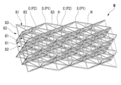
- the non-thermal expansion member M is formed in a plate shape, and has a plurality of base plates 81 arranged in parallel with each other at intervals in the thickness direction, and the base plates 81 with respect to each other. And a connecting three-dimensional truss structure 82 (having a non-thermal expansion structure). Both the base plate 81 and the three-dimensional truss structure 82 are made of a metal material.
- the linear expansion coefficient of the first material forming the base plate 81 is relatively larger than the linear expansion coefficient of the second material forming the three-dimensional truss structure 82.
- the plurality of base plates 81 face each other at equal intervals over the entire extension region.
- the three-dimensional truss structure 82 has a plurality of beams 83 extending in directions intersecting with each other. Each beam 83 has a rod shape.
- four beams 83 are one of a plurality of support points arranged in a grid pattern on the surface of one side base plate 81 of the pair of base plates 81 facing each other (first The support point P1) is connected to four support points (second support points P2) arranged in a grid on the surface of the base plate 81 on the other side.
- the base plate 81 includes a support portion S that forms a first support point P1 by connecting a plurality of (four) beams 83, and a plurality of support portions that are adjacent to each other in the spreading direction (plane direction) of the base plate 81. And a connecting portion C for connecting S.
- the base plate 81 is formed with a quadrangular hole (base plate hole portion H) having a plurality of (four) first support points P1 as vertices. That is, the base plate 81 has a grid shape that connects the first support points P1 to each other.
- the first support points P1 and the second support points P2 are arranged so that their positions do not overlap each other, and are arranged in a grid pattern at equal intervals.
- the four beams 83 form a quadrangular pyramid having a quadrangle formed on the base plate 81 by the four second support points P2 as the apex with the one first support point P1 as the apex. ..
- the plurality of beams 83 have the same length as each other.
- the three-dimensional truss structure 82 as described above is arranged so as to be mirror-image symmetric in the stacking direction with the base plate 81 sandwiched therebetween.
- the other first support point P1 is located on the opposite side of the one side surface of the base plate 81 from the one first support point P1 (on the other side surface of the base plate 81).
- FIG. 3 shows a configuration in which the unit structure including the base plate 81 and the three-dimensional truss structure 82 is laminated in four layers.
- FIG. 4 representatively shows only the pair of base plates 81 and the one-layer three-dimensional truss structure 82 provided between the base plates 81.
- the base plate 81 and the three-dimensional truss structure 82 exhibit the following behavior.
- the base plate 81 expands in the plane direction in which the base plate 81 extends (expands in the Da direction in FIG. 4: base plate 1a). Therefore, the interval between the first support points P1 described above increases (first support point P1a).
- the thermal expansion amount of the beam 83 is smaller than the thermal expansion amount of the base plate 81.
- the interval between the first support points P1 described above widens, and the pair of beams 83 are pulled in the direction in which the base plate 81 expands (beams 83a).
- a force that displaces the base plate 81 on the other side in the approaching direction acts on the base plate 81 on the one side. Due to this force, the base plate 81 on the other side is displaced in the Db direction in FIG.
- the thermal deformation becomes zero (or a negative value) in the thickness direction (stacking direction) orthogonal to the plane direction, or the first material and the first material It is a very small positive value compared to the case where the two materials are used alone.
- the behavior of the base plate 1 is exaggerated for the sake of explanation. That is, actually, the base plates 1 are not displaced in the directions in which they approach each other, and the thermal deformation in the stacking direction is zero (or an extremely small value).
- the non-thermal expansion member M described above can realize characteristics that have not been obtained in the past.
- the stacking direction of the base plates 81 is the circumferential direction with respect to the axis Am. Therefore, the size of the stator blade retaining ring 30 in the circumferential direction does not change or decreases. Therefore, the inner diameter of the annular stationary blade retaining ring 30 does not change or slightly increases. As a result, it is possible to reduce the possibility that the clearance C1 between the tip end portion of the compressor blade 14 and the inner peripheral surface 31S of the stationary blade retaining ring 30 changes significantly.
- the annular member body A has the non-thermal expansion structure.
- This non-thermal expansion structure is formed by a non-thermal expansion member M having a base plate 81 laminated at intervals and a plurality of beams 83 connecting the base plates 81 to each other.
- the first material forming the base plate 81 has a larger linear expansion coefficient than the second material forming the beams 83. Therefore, when heat is applied to the annular member main body A, the base plate 81 undergoes thermal deformation in the surface direction thereof, while the thermal deformation occurring in the beam 83 becomes small. As a result, the amount of thermal deformation of the base plate 81 in the stacking direction becomes zero or a negative value.
- the stacking direction of the base plates 81 is the circumferential direction of the annular member body A. Therefore, the thermal deformation of the annular member body A in this direction is zero or a negative value.
- the annular member main body A as the stationary blade retaining ring 30 has a non-thermal expansion structure, and in the non-thermal expansion structure, the base plate 81 is laminated in the circumferential direction of the annular member main body A. Has been done. As a result, the thermal deformation of the stationary blade retaining ring 30 in the circumferential direction becomes zero or a negative value. Therefore, the inner diameter of the stator blade retaining ring 30 does not change, or changes only slightly. As a result, it is possible to reduce the possibility that the clearance C1 between the tip of the compressor blade 14 and the stationary blade retaining ring 30 becomes excessively large. Thereby, the efficiency of the gas turbine 100 can be improved.
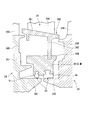
- a cylindrical turbine blade ring 50 attached to the end of the turbine blade ring 50 and a split ring 70 supported on the inner peripheral side of the turbine blade ring 50 via a heat shield ring 60 are provided.
- the split ring 70 has an annular shape centered on the axis Am.
- the inner peripheral surface 70S of the split ring 70 faces the tip portion (radially outer end portion) of the turbine rotor blade 24 with a clearance C2.
- the turbine blade ring 50 is formed of the non-thermal expansion member M described above.
- the stacking direction of the base plates 81 in the non-thermal expansion member M is the circumferential direction with respect to the axis Am.
- the annular member main body B as the turbine blade ring 50 has a non-thermal expansion structure, and in the non-thermal expansion structure, the stacking direction of the base plates 81 is the circumferential direction of the annular member main body B. ..
- the thermal deformation of the turbine blade ring 50 in the circumferential direction becomes zero, or a negative value, or a very small positive value as compared with the case where the first material and the second material are used alone. Therefore, the inner diameter dimension of the turbine blade ring 50 does not change, or changes only in a slightly increasing direction.
- the heat shield ring 60 is provided to support the split ring 70 on the inner peripheral side of the turbine blade ring 50.
- the heat shield ring 60 has a plurality of heat shield ring pieces arranged in the circumferential direction of the axis Am.
- the heat shield ring 60 as a whole has an annular shape centered on the axis Am.
- the stacking direction of the base plates 81 described above is the radial direction with respect to the axis Am.
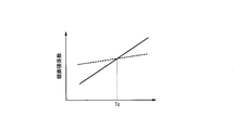
- the linear expansion coefficient of the first material forming the base plate 81 is the same as that of the second material forming the beam 83 at a temperature (first temperature) equal to or lower than the threshold value Tc. It is larger than the linear expansion coefficient (solid line graph).
- Tc threshold value
- a 5Cr-1Mo-based alloy can be suitably used as the first material exhibiting such characteristics, and a 5Ni-1/4Mo-based alloy can be suitably used as the second material.
- a 12Cr (or 13Cr) alloy as the first material and a 9Cr-1Mo alloy as the second material.
- stainless steel SUS304, SUS310, SUS316, SUS410
- Ti6Al4V Ti6Al4V
- Ni-based alloy Inconel 600, 718
- a material selected from 2.25Cr-1Mo material and the like is appropriately used.
- SUS304 is used as the first material and SUS410 having a smaller linear expansion coefficient than the SUS304 is used as the second material. It is also possible to use SUS304 as the first material and Ti6Al4V as the second material. In addition, aluminum alloy, copper, and carbon steel can be used as the first material or the second material.
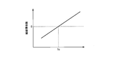
- the non-thermal expansion member M′ forming the heat shield ring 60 which is formed of the first material and the second material as described above, exhibits a linear expansion coefficient as shown in FIG. 8. Specifically, zero or a negative linear expansion coefficient is shown in a temperature region below the threshold Tc, and a positive linear expansion coefficient is shown in a temperature region higher than the threshold Tc.
- the annular member body C has the non-thermal expansion structure.
- This non-thermal expansion structure is formed by a non-thermal expansion member M′ having base plates 81 laminated at intervals and a plurality of beams 83 connecting the base plates 81 to each other.
- the first material forming the base plate 81 has a larger linear expansion coefficient than the second material forming the beams 83. Therefore, when heat is applied to the annular member main body C, the base plate 81 undergoes thermal deformation in the surface direction thereof, while the thermal deformation occurring in the beam 83 becomes small. As a result, the amount of thermal deformation of the base plate 81 in the stacking direction becomes zero or a negative value.
- the stacking direction of the base plates 81 is the radial direction of the annular member body C. Therefore, the thermal deformation of the annular member body C in this direction is zero or a negative value.
- the linear expansion coefficient of the first material forming the base plate 81 is larger than the linear expansion coefficient of the second material at the predetermined first temperature or lower. Therefore, below the said 1st temperature, a non-thermal expansion member shows zero or a negative linear expansion coefficient.
- the linear expansion coefficient of the first material changes smaller than the linear expansion coefficient of the second material. Therefore, at the second temperature, the non-thermal expansion member exhibits a positive linear expansion coefficient.
- a member for a rotary machine it is suitable for a member that requires a change in the linear expansion coefficient as described above, for example, from the start of operation to a steady state in order to keep a constant clearance with other members. Can be applied to.
- the non-thermal expansion member M′ is applied to the heat shield ring 60.
- the annular member body C as the heat shield ring 60 has a negative linear expansion coefficient, and thus contracts as a whole.
- the turbine rotor blades 24 gradually undergo thermal expansion from the cold state. Therefore, if no measures are taken, the clearance C2 between the split ring 70 and the turbine rotor blade 24 becomes small.
- the clearance C2 between the split ring 70 and the radially outer end of the turbine rotor blade 24 is increased by the first contraction of the heat shield ring 60 having the non-thermal expansion structure. Changes to. Further, when the steady state is reached, the linear expansion coefficient of the heat shield ring 60 becomes positive. As a result, the heat shield ring 60 expands and the clearance C2 changes in the direction of decreasing. Therefore, it is possible to maintain the size of the clearance C2 at a constant value immediately after the start of operation until reaching a steady state. As a result, the efficiency of the gas turbine 100 can be further improved.
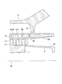
- each turbine rotor blade 24 includes a turbine rotor blade body 24A and a platform 24B that supports the turbine rotor blade body 24A on the outer peripheral surface of the turbine rotor 21.
- the platform 24B has a platform main body 241 extending in the radial direction with respect to the axis Am, and projecting portions 242 extending from the radial inside of the platform main body 241 to both sides in the axial Am direction, respectively.
- the overhanging portion 242 of the turbine rotor blade 24 on one side in the axis Am direction faces the overhanging portion 242 of another turbine rotor blade 24 adjacent to the other side in the axis Am direction.
- the turbine vane 26 includes a turbine vane main body 26A, an inner shroud 26B provided at an inner end of the turbine vane main body 26A in a radial direction, and a seal ring retaining ring further radially inward of the inner shroud 26B. 90 and.
- the inner shroud 26B has a plate-shaped shroud main body 261 connected to the turbine vane main body 26A, and a connecting portion 262 projecting radially inward from the shroud main body 261.
- the seal ring holding ring 90 has an annular shape centered on the axis Am, and an insertion groove 90R into which the above-mentioned connecting portion 262 is inserted is formed on an end surface facing outward in the radial direction.
- a plurality (two) of seal rings Sr are attached to the end surface of the seal ring holding ring 90 on the radially inner side.
- the seal ring Sr located on one side in the axial line Am direction faces the overhanging portion 242 of the turbine moving blade 24 on one side of the pair of turbine moving blades 24 adjacent to each other with a clearance C3.
- the seal ring Sr located on the other side in the direction of the axis Am faces the overhanging portion 242 of the turbine rotor blade 24 on the other side with a clearance C3.
- the seal ring Sr is provided to seal the leakage of fluid through the clearance C3.
- the seal ring holding ring 90 is formed of the non-thermal expansion member M described above.
- the stacking direction of the base plates 81 in the non-thermal expansion member M is the circumferential direction with respect to the axis Am.
- the annular member main body D as the seal ring holding ring 90 has a non-thermal expansion structure, and in the non-thermal expansion structure, the stacking direction of the base plates 81 is the circumferential direction of the annular member main body D.
- the thermal deformation of the seal ring retaining ring 90 in the circumferential direction becomes zero or a negative value. Therefore, the inner diameter of the seal ring holding ring 90 does not change, or changes only in a slightly increasing direction.
- FIG. 10 in the present embodiment, a film-shaped film member W that covers at least a part of the stationary blade retaining ring 30 is provided outside the stationary blade retaining ring 30 described in the first embodiment. There is. In the example of FIG. 10, the entire outer surface of the stationary blade retaining ring 30 is covered with the film member W.
- the non-thermal expansion structure M spaces are formed between the base plates 81 adjacent to each other and the beams 83 adjacent to each other. If a fluid flows into this space, it may lead to inadvertent pressure loss and obstruction of the flow.
- at least a part of the surface of the stationary blade retaining ring 30 formed by the non-thermal expansion structure M is covered with the film member W. Therefore, it is possible to prevent the fluid from flowing into the space. As a result, the pressure loss and the disturbance with respect to the flow can be avoided, and the efficiency of the gas turbine 100 can be further improved.
- a partition member W2 made of the same material as the film member W can be provided not only on the outer surface of the stationary blade retaining ring 30, but also on the inner surface thereof.
- the partition member W2 divides the inside of the stationary blade retaining ring 30 into a plurality of sections. With this configuration, the rigidity of the stationary blade retaining ring 30 can be further increased.
- film member W described in the present embodiment can be applied to each of the annular member bodies B, C, and D described in the above-described first to fourth embodiments.
- the present invention can be applied to members for rotary machines.
Landscapes
- Engineering & Computer Science (AREA)
- Mechanical Engineering (AREA)
- General Engineering & Computer Science (AREA)
- Chemical & Material Sciences (AREA)
- Combustion & Propulsion (AREA)
- Structures Of Non-Positive Displacement Pumps (AREA)
Abstract
回転機械用部材は、軸線(Am)を中心として周方向に延びる環状部材本体(A)を有し、環状部材本体Aは、第一材料からなり周方向に複数が間隔をあけて積層されたベース板、及び、第二材料からなり互いに隣り合うベース板同士を接続する複数の梁を有し、第一材料の線膨張係数は、第二材料の線膨張係数より大きい非熱膨張構造を有する。
Description
本発明は、回転機械用部材に関する。
本願は、2019年2月25日に、日本に出願された特願2019-031228号に基づき優先権を主張し、その内容をここに援用する。
本願は、2019年2月25日に、日本に出願された特願2019-031228号に基づき優先権を主張し、その内容をここに援用する。
ガスタービンは、圧縮機と、燃焼器と、タービンとを備えている。圧縮機は外部の空気を圧縮して高圧空気を生成する。燃焼器は、この高圧空気と燃料を混合して燃焼させることで高温高圧の燃焼ガスを生成する。タービンは、この燃焼ガスによって回転駆動される。ここで、圧縮機の出口側(後段側)や、タービンの入口側では、高温の流体が常態的に流通している。したがって、当該領域を形成する部材には、熱の入力に伴う変形(熱変形)が生じる場合が多い。
ところで、例えばタービンの動翼先端と車室の内周面との間には、数mm程度のクリアランスが形成されることが一般的である。このクリアランスは、ロータの円滑な回転を保証するために形成されている。
しかしながら、上記のような熱変形が各部材に生じると、このクリアランスを正常に維持することができなくなる可能性がある。クリアランスが過度に小さくなったり、ロータの周方向において不均一になったりした場合、動翼が車室に接触してタービンを正常に運転できなくなる虞がある。
しかしながら、上記のような熱変形が各部材に生じると、このクリアランスを正常に維持することができなくなる可能性がある。クリアランスが過度に小さくなったり、ロータの周方向において不均一になったりした場合、動翼が車室に接触してタービンを正常に運転できなくなる虞がある。
そこで、下記特許文献1では、複合材料によってガスタービンの高温部材を構成することを提案している。この複合材料は、負の熱膨張率、又は負のポアソン比を有する第1の材料と、正の熱膨張率、又は正のポアソン比を有する第2の材料とを交互に積層することで形成されている。
したがって、熱に曝された場合、この複合材料中では、第1の材料が収縮するとともに、第2の材料が膨張する。その結果、複合材料全体としては熱膨張(熱変形)を生じないとされている。
したがって、熱に曝された場合、この複合材料中では、第1の材料が収縮するとともに、第2の材料が膨張する。その結果、複合材料全体としては熱膨張(熱変形)を生じないとされている。
しかしながら、上記特許文献1に記載された複合材料では、第1の材料、及び第2の材料を単に積層したものであるため、その収縮・膨張の方向を恣意的に規定することが難しい。一方で、ガスタービンの高温部材として用いるためには、上述のクリアランスを維持するために、熱変形量はもとより、熱変形の生じる方向も厳密に規定されることが望ましい。
本発明は、上記課題を解決するためになされたものであって、回転機械の効率をより一層向上させることが可能な回転機械用部材を提供することを目的とする。
本発明の一態様に係る回転機械用部材は、軸線を中心として周方向に延びる環状部材本体を有し、前記環状部材本体は、第一材料からなり前記周方向に複数が間隔をあけて積層されたベース板、及び、第二材料からなり互いに隣り合うベース板同士を接続する複数の梁を有する非熱膨張構造を有し、前記第一材料の線膨張係数は、前記第二材料の線膨張係数よりも大きい。
上記構成によれば、環状部材本体が非熱膨張構造を有する。この非熱膨張構造は、間隔をあけて積層されたベース板、及びこれらベース板同士を接続する複数の梁を有する非熱膨張部材によって形成されている。ベース板を形成する第一材料は、梁を形成する第二材料よりも線膨張係数が大きい。
したがって、環状部材本体に熱が加わった場合、ベース板では自身の面方向に熱変形を生じる一方で、梁に生じる熱変形は小さくなる。
その結果、ベース板の積層方向における熱変形量はゼロ、又は負の値となるか、第一材料及び第二材料をそれぞれ単独で用いた場合に比べて非常に小さな正の値となる。
上記の構成では、これらベース板の積層方向が、環状部材本体の周方向とされている。したがって、この方向における環状部材本体の熱変形はゼロ、又は負の値となる。周方向の熱変形を生じさせたくない部位に、このような回転機械用部材を適用することで、例えば熱変形に伴うクリアランスの過度な変化等を回避することができる。
したがって、環状部材本体に熱が加わった場合、ベース板では自身の面方向に熱変形を生じる一方で、梁に生じる熱変形は小さくなる。
その結果、ベース板の積層方向における熱変形量はゼロ、又は負の値となるか、第一材料及び第二材料をそれぞれ単独で用いた場合に比べて非常に小さな正の値となる。
上記の構成では、これらベース板の積層方向が、環状部材本体の周方向とされている。したがって、この方向における環状部材本体の熱変形はゼロ、又は負の値となる。周方向の熱変形を生じさせたくない部位に、このような回転機械用部材を適用することで、例えば熱変形に伴うクリアランスの過度な変化等を回避することができる。
上記回転機械用部材は、軸線回りに回転可能な圧縮機ロータと、前記圧縮機ロータを外周側から覆う筒状をなすとともに内周面複数の圧縮機静翼が設けられている圧縮機車室と、をさらに有し、前記環状部材本体は、前記複数の圧縮機静翼を前記圧縮機車室の内周側で支持する静翼保持環であってもよい。
上記構成によれば、静翼保持環としての環状部材本体が非熱膨張構造を有し、当該非熱膨張構造では、ベース板の積層方向が環状部材本体の周方向とされている。これにより、静翼保持環の周方向における熱変形はゼロ、又は負の値となる。
したがって、静翼保持環の内径寸法は変化しないか、又はわずかに大きくなる方向に変化するのみとなる。その結果、圧縮機動翼の先端と静翼保持環との間のクリアランスが過度に大きくなる可能性を低減することができる。
したがって、静翼保持環の内径寸法は変化しないか、又はわずかに大きくなる方向に変化するのみとなる。その結果、圧縮機動翼の先端と静翼保持環との間のクリアランスが過度に大きくなる可能性を低減することができる。
上記回転機械用部材は、軸線回りに回転可能なタービンロータと、該タービンロータの外周面に設けられた複数のタービン動翼と、前記タービンロータを外周側から覆う筒状をなすとともに内周面に複数のタービン静翼が設けられているタービン車室と、前記タービン動翼の径方向外側の端部と径方向にクリアランスを介して配置され、軸線を中心とする円環状の分割環と、をさらに有し、前記環状部材本体は、前記分割環を前記タービン車室の内周側で支持するタービン翼環であってもよい。
上記構成によれば、タービン翼環としての環状部材本体が非熱膨張構造を有し、当該非熱膨張構造では、ベース板の積層方向が環状部材本体の周方向とされている。これにより、タービン翼環の周方向における熱変形はゼロ、又は負の値となる。したがって、タービン翼環の内径寸法は変化しないか、又はわずかに大きくなる方向に変化するのみとなる。
その結果、タービン翼環によって内周側で支持されている分割環と、タービン動翼の径方向外側の端部との間のクリアランスが過度に大きくなる可能性を低減することができる。
その結果、タービン翼環によって内周側で支持されている分割環と、タービン動翼の径方向外側の端部との間のクリアランスが過度に大きくなる可能性を低減することができる。
上記回転機械用部材は、軸線回りに回転可能なタービンロータと、前記タービンロータを外周側から覆う筒状をなすとともに内周面に複数のタービン静翼が設けられているタービン車室と、前記タービン静翼の径方向内側の端部と前記タービンロータとの間における流体の漏れをシールするシールリングと、をさらに有し、前記環状部材本体は、前記シールリングを前記タービン静翼の径方向内側の端部で支持するシールリング保持環であってもよい。
上記構成によれば、シールリング保持環としての環状部材本体が非熱膨張構造を有し、当該非熱膨張構造では、ベース板の積層方向が環状部材本体の周方向とされている。これにより、シールリング保持環の周方向における熱変形はゼロ、又は負の値となる。したがって、シールリング保持環の内径寸法は変化しないか、又はわずかに大きくなる方向に変化するのみとなる。
その結果、シールリング保持環によって内周側で支持されているシールリングと、タービンロータとの間におけるクリアランスが過度に大きくなる可能性を低減することができる。
その結果、シールリング保持環によって内周側で支持されているシールリングと、タービンロータとの間におけるクリアランスが過度に大きくなる可能性を低減することができる。
上記回転機械用部材は、前記環状部材本体の前記非熱膨張構造の表面の少なくとも一部を覆う膜部材をさらに有してもよい。
環状部材本体を構成する非熱膨張構造では、互いに隣り合うベース板同士、及び梁同士の間に空間が形成されている。この空間内に流体が流れ込んだ場合、不用意な圧力損失や流れの阻害につながる可能性がある。
しかしながら、上記の構成では、当該非熱膨張構造の表面の少なくとも一部が膜部材で覆われている。したがって、上記の空間に対する流体の流入を抑止することができる。
しかしながら、上記の構成では、当該非熱膨張構造の表面の少なくとも一部が膜部材で覆われている。したがって、上記の空間に対する流体の流入を抑止することができる。
上記回転機械用部材では、軸線を中心として周方向に延びる環状部材本体を有し、前記環状部材本体は、第一材料からなり前記軸線の径方向に複数が間隔をあけて積層されたベース板、及び、第二材料からなり互いに隣り合うベース板同士を接続する複数の梁を有する非熱膨張構造を有し、前記第一材料の線膨張係数は、前記第二材料の線膨張係数より大きい。
上記構成によれば、環状部材本体が非熱膨張構造を有する。この非熱膨張構造は、間隔をあけて積層されたベース板、及びこれらベース板同士を接続する複数の梁を有する非熱膨張部材によって形成されている。ベース板を形成する第一材料は、梁を形成する第二材料よりも線膨張係数が大きい。
したがって、環状部材本体に熱が加わった場合、ベース板では自身の面方向に熱変形を生じる一方で、梁に生じる熱変形は小さくなる。その結果、ベース板の積層方向における熱変形量はゼロ、又は負の値となるか、第一材料及び第二材料をそれぞれ単独で用いた場合に比べて非常に小さな正の値となる。
上記の構成では、これらベース板の積層方向が、環状部材本体の径方向とされている。したがって、この方向における環状部材本体の熱変形はゼロ、又は負の値となる。径方向の熱変形を生じさせたくない部位に、このような回転機械用部材を適用することで、例えば熱変形に伴うクリアランスの過度な変化等を回避することができる。
したがって、環状部材本体に熱が加わった場合、ベース板では自身の面方向に熱変形を生じる一方で、梁に生じる熱変形は小さくなる。その結果、ベース板の積層方向における熱変形量はゼロ、又は負の値となるか、第一材料及び第二材料をそれぞれ単独で用いた場合に比べて非常に小さな正の値となる。
上記の構成では、これらベース板の積層方向が、環状部材本体の径方向とされている。したがって、この方向における環状部材本体の熱変形はゼロ、又は負の値となる。径方向の熱変形を生じさせたくない部位に、このような回転機械用部材を適用することで、例えば熱変形に伴うクリアランスの過度な変化等を回避することができる。
本発明の一態様に係る回転機械用部材は、軸線を中心として周方向に延びる環状部材本体を有し、前記環状部材本体は、第一材料からなり前記軸線の径方向に複数が間隔をあけて積層されたベース板、及び、第二材料からなり互いに隣り合う前記ベース板同士を接続する複数の梁を有する非熱膨張構造を有し、前記第一材料の線膨張係数は、第一の温度で前記第二材料の線膨張係数よりも大きいとともに、前記第一の温度よりも高い第二の温度では前記第二材料の線膨張係数よりも小さい。
上記構成によれば、第一の温度以下では、ベース板を構成する第一材料の線膨張係数は、第二材料の線膨張係数よりも大きい。したがって、当該第一温度以下では、非熱膨張部材は、ゼロ又は負の線膨張係数を示す。
一方で、第一の温度よりも大きい第二の温度では、第一材料の線膨張係数は第二材料の線膨張係数よりも小さく変化する。したがって、当該第二温度では、非熱膨張係数は、正の線膨張係数を示す。回転機械用部材としては、他の部材との間のクリアランスを一定に保つ上で、例えば運転開始から定常状態に至るまでの間に上記のような線膨張係数の変化が必要となる部材に好適に適用することができる。
一方で、第一の温度よりも大きい第二の温度では、第一材料の線膨張係数は第二材料の線膨張係数よりも小さく変化する。したがって、当該第二温度では、非熱膨張係数は、正の線膨張係数を示す。回転機械用部材としては、他の部材との間のクリアランスを一定に保つ上で、例えば運転開始から定常状態に至るまでの間に上記のような線膨張係数の変化が必要となる部材に好適に適用することができる。
上記回転機械用部材は、軸線回りに回転可能なタービンロータと、該タービンロータの外周面に設けられた複数のタービン動翼と、前記タービンロータを外周側から覆う筒状をなすとともに内周面に複数のタービン静翼が設けられているタービン車室と、前記タービン動翼の径方向外側の端部と径方向にクリアランスを介して配置され、前記軸線を中心とする円環状の分割環と、前記分割環を前記タービン車室の内周側で支持するタービン翼環と、前記環状部材本体は、前記タービン翼環と前記分割環との間に設けられた遮熱環であってもよい。
上記構成によれば、温度が低い(第一の温度以下である)場合、遮熱環としての環状部材本体は、負の線膨張係数を示すことから、全体として収縮する。一方で、温度が低い運転域(即ち、運転開始直後)では、タービン動翼が熱膨張する。したがって、何らの措置も施さない場合、分割環とタービン動翼との間のクリアランスは小さくなってしまう。
しかしながら、上記構成によれば、非熱膨張構造を有する遮熱環がはじめに収縮することにより、分割環とタービン動翼の径方向外側の端部との間のクリアランスは大きくなる方向に変化する。
さらに、定常状態に至ると、遮熱環の線膨張係数は正となる。これにより、遮熱環は膨張し、クリアランスは小さくなる方向に変化する。
したがって、運転開始直後から定常状態に至るまで、クリアランスの大きさを一定の値で維持することが可能となる。その結果、ガスタービンの効率をさらに向上させることができる。
しかしながら、上記構成によれば、非熱膨張構造を有する遮熱環がはじめに収縮することにより、分割環とタービン動翼の径方向外側の端部との間のクリアランスは大きくなる方向に変化する。
さらに、定常状態に至ると、遮熱環の線膨張係数は正となる。これにより、遮熱環は膨張し、クリアランスは小さくなる方向に変化する。
したがって、運転開始直後から定常状態に至るまで、クリアランスの大きさを一定の値で維持することが可能となる。その結果、ガスタービンの効率をさらに向上させることができる。
上記回転機械用部材では、前記環状部材本体の前記非熱膨張構造の表面の少なくとも一部を覆う膜状の膜部材をさらに有してもよい。
環状部材本体を構成する非熱膨張構造では、互いに隣り合うベース板同士、及び梁同士の間に空間が形成されている。この空間内に流体が流れ込んだ場合、不用意な圧力損失や流れの阻害につながる可能性がある。
しかしながら、上記の構成では、当該非熱膨張構造の表面の少なくとも一部が膜部材で覆われている。したがって、上記の空間に対する流体の流入を抑止することができる。
しかしながら、上記の構成では、当該非熱膨張構造の表面の少なくとも一部が膜部材で覆われている。したがって、上記の空間に対する流体の流入を抑止することができる。
本発明によれば、回転機械の効率をより一層向上させることが可能な回転機械用部材を提供することができる。
[第一実施形態]
本発明の第一実施形態について、図1から図4を参照して説明する。ガスタービン100は、圧縮機1と、燃焼器3と、タービン2と、を備えている。
本発明の第一実施形態について、図1から図4を参照して説明する。ガスタービン100は、圧縮機1と、燃焼器3と、タービン2と、を備えている。
圧縮機1は、高圧空気を生成する。圧縮機1は、回転機械用部材としての、圧縮機ロータ11と、圧縮機ケーシング12(圧縮機車室)と、を備えている。
圧縮機ケーシング12は、圧縮機ロータ11を外周側から覆っており、軸線Amに沿って延びている。
圧縮機ケーシング12は、圧縮機ロータ11を外周側から覆っており、軸線Amに沿って延びている。
圧縮機ロータ11の外周面には、軸線Am方向に間隔をあけて配列された複数の圧縮機動翼段13が設けられている。これら圧縮機動翼段13は、複数の圧縮機動翼14をそれぞれ備えている。各圧縮機動翼段13の圧縮機動翼14は、圧縮機ロータ11の外周面上で軸線Amの周方向に間隔をあけて配列されている。
圧縮機ケーシング12の内周面には、軸線Am方向に間隔をあけて配列された複数の圧縮機静翼段15が設けられている。これら圧縮機静翼段15は、軸線Am方向で上記圧縮機動翼段13と交互に配置されている。これら圧縮機静翼段15は、複数の圧縮機静翼16をそれぞれ備えている。各圧縮機静翼段15の圧縮機静翼16は、圧縮機ケーシング12の内周面上で軸線Amの周方向に間隔をあけて配列されている。
燃焼器3は、圧縮機1で生成された高圧空気に燃料を混合して燃焼させることで燃焼ガスを生成する。燃焼器3は、圧縮機ケーシング12とタービン2のタービンケーシング22との間に設けられている。この燃焼器3によって生成された燃焼ガスは、タービン2に供給される。
タービン2は、燃焼器3で生成された燃焼ガスによって駆動する。このタービン2は、回転機械用部材としての、タービンロータ21と、タービンケーシング22(タービン車室)と、を有している。
タービンロータ21は、軸線Amに沿って延びている。このタービンロータ21の外周面には、軸線Am方向に間隔をあけて配列された複数のタービン動翼段23が設けられている。これらタービン動翼段23は、複数のタービン動翼24をそれぞれ備えている。各タービン動翼段23のタービン動翼24は、タービンロータ21の外周面上で軸線Amの周方向に間隔をあけて配列されている。
タービンロータ21は、軸線Amに沿って延びている。このタービンロータ21の外周面には、軸線Am方向に間隔をあけて配列された複数のタービン動翼段23が設けられている。これらタービン動翼段23は、複数のタービン動翼24をそれぞれ備えている。各タービン動翼段23のタービン動翼24は、タービンロータ21の外周面上で軸線Amの周方向に間隔をあけて配列されている。
タービンケーシング22は、タービンロータ21を外周側から覆っている。このタービンケーシング22の内周面には、軸線Am方向に間隔をあけて配列された複数のタービン静翼段25が設けられている。
タービン静翼段25は、軸線Am方向で上記タービン動翼段23と交互に配置されている。これらタービン静翼段25は、複数のタービン静翼26をそれぞれ備えている。各タービン静翼段25のタービン静翼26は、タービンケーシング22の内周面上で軸線Amの周方向に間隔をあけて配列されている。
タービン静翼段25は、軸線Am方向で上記タービン動翼段23と交互に配置されている。これらタービン静翼段25は、複数のタービン静翼26をそれぞれ備えている。各タービン静翼段25のタービン静翼26は、タービンケーシング22の内周面上で軸線Amの周方向に間隔をあけて配列されている。
圧縮機ロータ11とタービンロータ21とは、軸線Am方向に一体に接続されている。これら圧縮機ロータ11とタービンロータ21とによって、ガスタービンロータ91(タービンロータ)が構成されている。同様に、圧縮機ケーシング12とタービンケーシング22とは、軸線Amに沿って一体に接続されている。これら圧縮機ケーシング12とタービンケーシング22とによってガスタービンケーシング92(車室)が構成されている。
ガスタービンロータ91は、ガスタービンケーシング92の内部で軸線Am回りに一体に回転可能とされている。
ガスタービンロータ91は、ガスタービンケーシング92の内部で軸線Am回りに一体に回転可能とされている。
ガスタービン100を運転するに当たっては、まず外部の駆動源によって圧縮機ロータ11(ガスタービンロータ91)を回転駆動する。圧縮機ロータ11の回転に伴って外部の空気が順次圧縮され、高圧空気が生成される。この高圧空気は、圧縮機ケーシング12を通じて燃焼器3内に供給される。燃焼器3内では、燃料がこの高圧空気に混合されて燃焼し、高温高圧の燃焼ガスが生成される。
燃焼ガスはタービンケーシング22を通じてタービン2内に供給される。タービン2内では、タービン動翼段23、及びタービン静翼段25に燃焼ガスが順次衝突することで、タービンロータ21(ガスタービンロータ91)に対して回転駆動力が与えられる。
この回転エネルギーは、例えば、軸端に連結された発電機G等の駆動に利用される。タービン2を駆動した燃焼ガスは外部に排出される。
燃焼ガスはタービンケーシング22を通じてタービン2内に供給される。タービン2内では、タービン動翼段23、及びタービン静翼段25に燃焼ガスが順次衝突することで、タービンロータ21(ガスタービンロータ91)に対して回転駆動力が与えられる。
この回転エネルギーは、例えば、軸端に連結された発電機G等の駆動に利用される。タービン2を駆動した燃焼ガスは外部に排出される。
次いで、図2を参照して、圧縮機1の内部の構成について説明する。同図に示すように、圧縮機1では、上述の圧縮機静翼16が、圧縮機ケーシング12の内部で、静翼保持環30(環状部材本体A)によって保持されている。
具体的には、この静翼保持環30は、圧縮機ケーシング12の内周面から軸線Amに対する径方向内側に向かって突出する突出部S1の先端(径方向内側の端部)に固定されている。
静翼保持環30は、軸線Amを中心とする筒状をなしている。静翼保持環30のうち、軸線Am方向一方側の端部を含む部分(即ち、上記の突出部S1よりも軸線Am方向一方側の部分)の内周面31Sには、複数の圧縮機静翼16が軸線Am方向に間隔をあけて配列されている。
一対の圧縮機静翼16同士の間には1つの圧縮機動翼14が入り込んでいる。圧縮機動翼14の先端部(径方向外側の端部)と内周面31Sとの間には、径方向に広がるクリアランスC1が形成されている。
具体的には、この静翼保持環30は、圧縮機ケーシング12の内周面から軸線Amに対する径方向内側に向かって突出する突出部S1の先端(径方向内側の端部)に固定されている。
静翼保持環30は、軸線Amを中心とする筒状をなしている。静翼保持環30のうち、軸線Am方向一方側の端部を含む部分(即ち、上記の突出部S1よりも軸線Am方向一方側の部分)の内周面31Sには、複数の圧縮機静翼16が軸線Am方向に間隔をあけて配列されている。
一対の圧縮機静翼16同士の間には1つの圧縮機動翼14が入り込んでいる。圧縮機動翼14の先端部(径方向外側の端部)と内周面31Sとの間には、径方向に広がるクリアランスC1が形成されている。
静翼保持環30のうち、軸線Am方向他方側の端部を含む部分(即ち、上記の突出部S1よりも軸線Am方向他方側の部分)の内周面32Sは、軸線Am方向一方側から他方側に向かうに従って、径方向内側から外側に向かって延びている。
さらに、この内周面32Sは、ディフューザ5の外周面5Sに対して径方向外側から対向している。ディフューザ5は、圧縮機1から排出された高圧空気を案内し、静圧回復するために設けられている。
さらに、この内周面32Sは、ディフューザ5の外周面5Sに対して径方向外側から対向している。ディフューザ5は、圧縮機1から排出された高圧空気を案内し、静圧回復するために設けられている。
上記の静翼保持環30は、非熱膨張構造を有する非熱膨張部材Mによって形成されている。非熱膨張構造は、線膨張係数がゼロ、又は負の値を示すか、非常に小さな正の値を示す。
図3に示すように、非熱膨張部材Mは、板状に形成されるとともに、厚さ方向に間隔をあけて互いに平行に配列された複数のベース板81と、これらベース板81同士を互いに接続する三次元トラス構造82と、を備えている(非熱膨張構造を有している)。
これらベース板81、及び三次元トラス構造82は、いずれも金属材料で形成されている。ベース板81を形成する第一材料の線膨張係数は、三次元トラス構造82を形成する第二材料の線膨張係数に対して相対的に大きい。複数のベース板81は、延在領域の全体にわたって等間隔をあけて互いに対向している。
図3に示すように、非熱膨張部材Mは、板状に形成されるとともに、厚さ方向に間隔をあけて互いに平行に配列された複数のベース板81と、これらベース板81同士を互いに接続する三次元トラス構造82と、を備えている(非熱膨張構造を有している)。
これらベース板81、及び三次元トラス構造82は、いずれも金属材料で形成されている。ベース板81を形成する第一材料の線膨張係数は、三次元トラス構造82を形成する第二材料の線膨張係数に対して相対的に大きい。複数のベース板81は、延在領域の全体にわたって等間隔をあけて互いに対向している。
三次元トラス構造82は、互いに交差する方向に延びる複数の梁83を有している。それぞれの梁83は棒状をなしている。この三次元トラス構造82では、4つの梁83が、互いに対向する一対のベース板81のうち、一方側のベース板81の表面に格子状に配列された複数の支持点の一つ(第一支持点P1)と、他方側のベース板81の表面に格子状に配列された4つの支持点(第二支持点P2)とをそれぞれ接続している。
ベース板81は、複数(4つ)の梁83が接続されることで第一支持点P1を形成する支持部Sと、ベース板81の広がる方向(面方向)において互いに隣接する複数の支持部Sを接続する接続部Cと、を有している。
これにより、ベース板81には、複数(4つ)の第一支持点P1を頂点とする四角形の孔(ベース板孔部H)が形成されている。即ち、ベース板81は、各第一支持点P1同士を接続する格子状をなしている。
これにより、ベース板81には、複数(4つ)の第一支持点P1を頂点とする四角形の孔(ベース板孔部H)が形成されている。即ち、ベース板81は、各第一支持点P1同士を接続する格子状をなしている。
ベース板81に直交する方向から見て、第一支持点P1と第二支持点P2とは、位置が互いに重ならないようにそれぞれ配列されるとともに、互いに等間隔をあけて格子状に配列されている。
即ち、上記4つの梁83は、1つの第一支持点P1を頂点とするとともに、4つの第二支持点P2によってベース板81上に形成される四角形を底面とする四角錐を形成している。複数の梁83は、互いに同一の長さを有している。
即ち、上記4つの梁83は、1つの第一支持点P1を頂点とするとともに、4つの第二支持点P2によってベース板81上に形成される四角形を底面とする四角錐を形成している。複数の梁83は、互いに同一の長さを有している。
上記のような三次元トラス構造82が、ベース板81を挟んで積層方向に鏡像対称となるように配置されている。言い換えれば、ベース板81の一方側の面における1つの第一支持点P1の反対側(ベース板81の他方側の面上)には、他の第一支持点P1が位置している。
図3の例では、これらベース板81、及び三次元トラス構造82によって構成される単位構造が、4層にわたって積層されている構成を示している。
図3の例では、これらベース板81、及び三次元トラス構造82によって構成される単位構造が、4層にわたって積層されている構成を示している。
次に、上記の非熱膨張部材Mの挙動について、図4を参照して説明する。図4では、一対のベース板81と、これらベース板81同士の間に設けられた1層の三次元トラス構造82のみを代表的に示している。
非熱膨張部材Mに熱が加えられた場合、ベース板81、及び三次元トラス構造82は、以下のような挙動を示す。
まず、ベース板81は、自身の延在する面方向に膨張する(図4中のDa方向に膨張する:ベース板1a)。したがって、上述の第一支持点P1同士の間隔が広がる(第一支持点P1a)。
ここで、梁83の線膨張係数が、ベース板81の線膨張係数よりも小さいことから、ベース板81の熱膨張量に比べて、梁83の熱膨張量は小さくなっている。これにより、上述の第一支持点P1同士の間隔が広がり、一対の梁83はベース板81の膨張する方向へ引っ張られる(梁83a)。
その結果、一方側のベース板81に対して、他方側のベース板81を近付く方向に変位させる力が働く。この力により、他方側のベース板81は、図4中のDb方向に変位する。
このように、ベース板81の広がる面方向に膨張が生じる一方で、面方向に直交する厚さ方向(積層方向)では熱変形がゼロ(又は負の値)となるか、第一材料及び第二材料をそれぞれ単独で用いた場合に比べて非常に小さな正の値となる。
なお、図4の例では、説明のためにベース板1の挙動を誇張して示している。即ち、実際には、ベース板1同士は、互いに近付く方向には変位せず、積層方向における熱変形はゼロ(又は極めて小さい値)となる。
非熱膨張部材Mに熱が加えられた場合、ベース板81、及び三次元トラス構造82は、以下のような挙動を示す。
まず、ベース板81は、自身の延在する面方向に膨張する(図4中のDa方向に膨張する:ベース板1a)。したがって、上述の第一支持点P1同士の間隔が広がる(第一支持点P1a)。
ここで、梁83の線膨張係数が、ベース板81の線膨張係数よりも小さいことから、ベース板81の熱膨張量に比べて、梁83の熱膨張量は小さくなっている。これにより、上述の第一支持点P1同士の間隔が広がり、一対の梁83はベース板81の膨張する方向へ引っ張られる(梁83a)。
その結果、一方側のベース板81に対して、他方側のベース板81を近付く方向に変位させる力が働く。この力により、他方側のベース板81は、図4中のDb方向に変位する。
このように、ベース板81の広がる面方向に膨張が生じる一方で、面方向に直交する厚さ方向(積層方向)では熱変形がゼロ(又は負の値)となるか、第一材料及び第二材料をそれぞれ単独で用いた場合に比べて非常に小さな正の値となる。
なお、図4の例では、説明のためにベース板1の挙動を誇張して示している。即ち、実際には、ベース板1同士は、互いに近付く方向には変位せず、積層方向における熱変形はゼロ(又は極めて小さい値)となる。
他方で、上記のような非熱膨張部材Mとは異なる、一様な材料で形成された中実の板材に熱を加えた場合、面方向と厚さ方向のいずれにおいても熱膨張が生じてしまう。即ち、上記の非熱膨張部材Mでは、従来得られなかった特性を実現することができる。
本実施形態に係る静翼保持環30では、上記のベース板81の積層方向が、軸線Amに対する周方向とされている。したがって、周方向における静翼保持環30の寸法は変化しないか、又は減少する。よって、円環状をなす静翼保持環30の内径寸法は変化しないか、又はわずかに増大する。
その結果、圧縮機動翼14の先端部と静翼保持環30の内周面31Sとの間のクリアランスC1が大きく変化してしまう可能性を低減することができる。
その結果、圧縮機動翼14の先端部と静翼保持環30の内周面31Sとの間のクリアランスC1が大きく変化してしまう可能性を低減することができる。
以上、説明したように、上記構成によれば、環状部材本体Aが非熱膨張構造を有する。
この非熱膨張構造は、間隔をあけて積層されたベース板81、及びこれらベース板81同士を接続する複数の梁83を有する非熱膨張部材Mによって形成されている。ベース板81を形成する第一材料は、梁83を形成する第二材料よりも線膨張係数が大きい。
したがって、環状部材本体Aに熱が加わった場合、ベース板81では自身の面方向に熱変形を生じる一方で、梁83に生じる熱変形は小さくなる。その結果、ベース板81の積層方向における熱変形量はゼロ、又は負の値となる。上記の構成では、これらベース板81の積層方向が、環状部材本体Aの周方向とされている。
したがって、この方向における環状部材本体Aの熱変形はゼロ、又は負の値となる。周方向の熱変形を生じさせたくない部位に、このような回転機械用部材を適用することで、例えば熱変形に伴うクリアランスの過度な変化等を回避することができる。
この非熱膨張構造は、間隔をあけて積層されたベース板81、及びこれらベース板81同士を接続する複数の梁83を有する非熱膨張部材Mによって形成されている。ベース板81を形成する第一材料は、梁83を形成する第二材料よりも線膨張係数が大きい。
したがって、環状部材本体Aに熱が加わった場合、ベース板81では自身の面方向に熱変形を生じる一方で、梁83に生じる熱変形は小さくなる。その結果、ベース板81の積層方向における熱変形量はゼロ、又は負の値となる。上記の構成では、これらベース板81の積層方向が、環状部材本体Aの周方向とされている。
したがって、この方向における環状部材本体Aの熱変形はゼロ、又は負の値となる。周方向の熱変形を生じさせたくない部位に、このような回転機械用部材を適用することで、例えば熱変形に伴うクリアランスの過度な変化等を回避することができる。
さらに、上記構成によれば、静翼保持環30としての環状部材本体Aが非熱膨張構造を有し、当該非熱膨張構造では、ベース板81の積層方向が環状部材本体Aの周方向とされている。これにより、静翼保持環30の周方向における熱変形はゼロ、又は負の値となる。したがって、静翼保持環30の内径寸法は変化しないか、又はわずかに変化するのみとなる。
その結果、圧縮機動翼14の先端と静翼保持環30との間のクリアランスC1が過度に大きくなる可能性を低減することができる。これにより、ガスタービン100の効率を向上させることができる。
その結果、圧縮機動翼14の先端と静翼保持環30との間のクリアランスC1が過度に大きくなる可能性を低減することができる。これにより、ガスタービン100の効率を向上させることができる。
以上、本発明の第一実施形態について説明した。なお、本発明の要旨を逸脱しない限りにおいて、上記の構成に種々の変更や改修を施すことが可能である。
[第二実施形態]
次に、本発明の第二実施形態について、図5を参照して説明する。なお、上記の第一実施形態と同様の構成については同一の符号を付し、詳細な説明を省略する。本実施形態では、環状部材本体Bとして、タービン2内のタービン翼環50に上述の非熱膨張部材Mを適用した例について説明する。
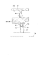
図5に示すように、タービンケーシング22(タービン車室)の内側には、タービンケーシング22の内周面22Sから径方向内側に向かって突出する突出部S2と、この突出部S2の径方向内側の端部に取り付けられた円筒状のタービン翼環50と、タービン翼環50の内周側で遮熱環60を介して支持されている分割環70とが設けられている。
分割環70は、軸線Amを中心とする円環状をなしている。分割環70の内周面70Sは、タービン動翼24の先端部(径方向外側の端部)に対して、クリアランスC2をあけて対向している。
次に、本発明の第二実施形態について、図5を参照して説明する。なお、上記の第一実施形態と同様の構成については同一の符号を付し、詳細な説明を省略する。本実施形態では、環状部材本体Bとして、タービン2内のタービン翼環50に上述の非熱膨張部材Mを適用した例について説明する。
図5に示すように、タービンケーシング22(タービン車室)の内側には、タービンケーシング22の内周面22Sから径方向内側に向かって突出する突出部S2と、この突出部S2の径方向内側の端部に取り付けられた円筒状のタービン翼環50と、タービン翼環50の内周側で遮熱環60を介して支持されている分割環70とが設けられている。
分割環70は、軸線Amを中心とする円環状をなしている。分割環70の内周面70Sは、タービン動翼24の先端部(径方向外側の端部)に対して、クリアランスC2をあけて対向している。
タービン翼環50は、上述の非熱膨張部材Mによって形成されている。当該非熱膨張部材Mにおけるベース板81の積層方向は、軸線Amに対する周方向とされている。
上記構成によれば、タービン翼環50としての環状部材本体Bが非熱膨張構造を有し、当該非熱膨張構造では、ベース板81の積層方向が環状部材本体Bの周方向とされている。これにより、タービン翼環50の周方向における熱変形はゼロ、又は負の値となるか、第一材料及び第二材料をそれぞれ単独で用いた場合に比べて非常に小さな正の値となる。
したがって、タービン翼環50の内径寸法は変化しないか、又はわずかに大きくなる方向に変化するのみとなる。その結果、タービン翼環50によって内周側で支持されている分割環70の内周面70Sと、タービン動翼24の径方向外側の端部との間のクリアランスC2が過度に大きくなる可能性を低減することができる。
したがって、タービン翼環50の内径寸法は変化しないか、又はわずかに大きくなる方向に変化するのみとなる。その結果、タービン翼環50によって内周側で支持されている分割環70の内周面70Sと、タービン動翼24の径方向外側の端部との間のクリアランスC2が過度に大きくなる可能性を低減することができる。
以上、本発明の第二実施形態について説明した。なお、本発明の要旨を逸脱しない限りにおいて、上記の構成に種々の変更や改修を施すことが可能である。
[第三実施形態]
次に、本発明の第三実施形態について、図6を参照して説明する。なお、上記の各実施形態と同様の構成については同一の符号を付し、詳細な説明を省略する。
本実施形態では、環状部材本体Cとして、タービン2内の遮熱環60に非熱膨張部材M´を適用した例について説明する。
図6に示すように、遮熱環60は、分割環70をタービン翼環50の内周側で支持するために設けられている。詳しくは図示しないが、遮熱環60は、軸線Amの周方向に配列された複数の遮熱環片を有している。遮熱環60は全体として軸線Amを中心とする円環状をなしている。
次に、本発明の第三実施形態について、図6を参照して説明する。なお、上記の各実施形態と同様の構成については同一の符号を付し、詳細な説明を省略する。
本実施形態では、環状部材本体Cとして、タービン2内の遮熱環60に非熱膨張部材M´を適用した例について説明する。
図6に示すように、遮熱環60は、分割環70をタービン翼環50の内周側で支持するために設けられている。詳しくは図示しないが、遮熱環60は、軸線Amの周方向に配列された複数の遮熱環片を有している。遮熱環60は全体として軸線Amを中心とする円環状をなしている。
遮熱環60を形成する非熱膨張部材M´では、上述のベース板81の積層方向が、軸線Amに対する径方向とされている。さらに、図7中の鎖線グラフで示すように、ベース板81を形成する第一材料の線膨張係数は、閾値Tc以下の温度(第一の温度)では、梁83を形成する第二材料の線膨張係数(実線グラフ)よりも大きい。
一方で、閾値Tcよりも高い温度(第二の温度)では、第一材料の線膨張係数は、第二材料の線膨張係数よりも小さくなる。
このような特性を示す第一材料としては5Cr-1Mo系合金を、第二材料としては5Ni-1/4Mo系合金を好適に用いることができる。
また、他の組み合わせとしては、第一材料として12Cr(又は13Cr)系合金を用い、第二材料として9Cr-1Mo系合金を用いることも可能である。
さらに他の例として、第一材料、及び第二材料として、ステンレス鋼(SUS304、SUS310、SUS316、SUS410)や、Ti6Al4V、Ni基合金(インコネル600、718)、高クロム鋼(9Cr、12Cr)、2.25Cr-1Mo材等から選択された材料が適宜用いられる。より具体的には、第一材料としてSUS304を用い、第二材料としてこのSUS304よりも線膨張係数が小さいSUS410を用いることが考えられる。
また、第一材料としてSUS304を用い、第二材料としてTi6Al4Vを用いることも可能である。この他、アルミ合金や銅、カーボンスチールを第一材料、又は第二材料として用いることも可能である。
一方で、閾値Tcよりも高い温度(第二の温度)では、第一材料の線膨張係数は、第二材料の線膨張係数よりも小さくなる。
このような特性を示す第一材料としては5Cr-1Mo系合金を、第二材料としては5Ni-1/4Mo系合金を好適に用いることができる。
また、他の組み合わせとしては、第一材料として12Cr(又は13Cr)系合金を用い、第二材料として9Cr-1Mo系合金を用いることも可能である。
さらに他の例として、第一材料、及び第二材料として、ステンレス鋼(SUS304、SUS310、SUS316、SUS410)や、Ti6Al4V、Ni基合金(インコネル600、718)、高クロム鋼(9Cr、12Cr)、2.25Cr-1Mo材等から選択された材料が適宜用いられる。より具体的には、第一材料としてSUS304を用い、第二材料としてこのSUS304よりも線膨張係数が小さいSUS410を用いることが考えられる。
また、第一材料としてSUS304を用い、第二材料としてTi6Al4Vを用いることも可能である。この他、アルミ合金や銅、カーボンスチールを第一材料、又は第二材料として用いることも可能である。
上記のような第一材料、及び第二材料で形成されていることにより、遮熱環60を形成する非熱膨張部材M´は、図8に示すような線膨張係数を示す。具体的には、閾値Tc以下の温度領域ではゼロ又は負の線膨張係数を示し、閾値Tcよりも高い温度領域では正の線膨張係数を示す。
上記構成によれば、環状部材本体Cが非熱膨張構造を有する。この非熱膨張構造は、間隔をあけて積層されたベース板81、及びこれらベース板81同士を接続する複数の梁83を有する非熱膨張部材M´によって形成されている。
ベース板81を形成する第一材料は、梁83を形成する第二材料よりも線膨張係数が大きい。したがって、環状部材本体Cに熱が加わった場合、ベース板81では自身の面方向に熱変形を生じる一方で、梁83に生じる熱変形は小さくなる。その結果、ベース板81の積層方向における熱変形量はゼロ、又は負の値となる。
上記の構成では、これらベース板81の積層方向が、環状部材本体Cの径方向とされている。したがって、この方向における環状部材本体Cの熱変形はゼロ、又は負の値となる。径方向の熱変形を生じさせたくない部位に、このような回転機械用部材を適用することで、例えば熱変形に伴うクリアランスの過度な変化等を回避することができる。
ベース板81を形成する第一材料は、梁83を形成する第二材料よりも線膨張係数が大きい。したがって、環状部材本体Cに熱が加わった場合、ベース板81では自身の面方向に熱変形を生じる一方で、梁83に生じる熱変形は小さくなる。その結果、ベース板81の積層方向における熱変形量はゼロ、又は負の値となる。
上記の構成では、これらベース板81の積層方向が、環状部材本体Cの径方向とされている。したがって、この方向における環状部材本体Cの熱変形はゼロ、又は負の値となる。径方向の熱変形を生じさせたくない部位に、このような回転機械用部材を適用することで、例えば熱変形に伴うクリアランスの過度な変化等を回避することができる。
さらに、上記構成によれば、予め定められた第一の温度以下では、ベース板81を構成する第一材料の線膨張係数は、第二材料の線膨張係数よりも大きい。したがって、当該第一温度以下では、非熱膨張部材は、ゼロ又は負の線膨張係数を示す。
一方で、第一の温度よりも大きい第二の温度では、第一材料の線膨張係数は第二材料の線膨張係数よりも小さく変化する。したがって、当該第二温度では、非熱膨張部材は、正の線膨張係数を示す。
回転機械用部材としては、他の部材との間のクリアランスを一定に保つ上で、例えば運転開始から定常状態に至るまでの間に上記のような線膨張係数の変化が必要となる部材に好適に適用することができる。
一方で、第一の温度よりも大きい第二の温度では、第一材料の線膨張係数は第二材料の線膨張係数よりも小さく変化する。したがって、当該第二温度では、非熱膨張部材は、正の線膨張係数を示す。
回転機械用部材としては、他の部材との間のクリアランスを一定に保つ上で、例えば運転開始から定常状態に至るまでの間に上記のような線膨張係数の変化が必要となる部材に好適に適用することができる。
そこで、上記実施形態では、遮熱環60に非熱膨張部材M´を適用している。温度が低い(第一の温度以下である)場合、遮熱環60としての環状部材本体Cは、負の線膨張係数を示すことから、全体として収縮する。
一方で、温度が低い運転域(即ち、運転開始直後)では、タービン動翼24が冷間状態から徐々に熱膨張する。したがって、何らの措置も施さない場合、分割環70とタービン動翼24との間のクリアランスC2は小さくなってしまう。
しかしながら、上記構成によれば、非熱膨張構造を有する遮熱環60がはじめに収縮することにより、分割環70とタービン動翼24の径方向外側の端部との間のクリアランスC2は大きくなる方向に変化する。さらに、定常状態に至ると、遮熱環60の線膨張係数は正となる。
これにより、遮熱環60は膨張し、クリアランスC2は小さくなる方向に変化する。したがって、運転開始直後から定常状態に至るまで、クリアランスC2の大きさを一定の値で維持することが可能となる。その結果、ガスタービン100の効率をさらに向上させることができる。
一方で、温度が低い運転域(即ち、運転開始直後)では、タービン動翼24が冷間状態から徐々に熱膨張する。したがって、何らの措置も施さない場合、分割環70とタービン動翼24との間のクリアランスC2は小さくなってしまう。
しかしながら、上記構成によれば、非熱膨張構造を有する遮熱環60がはじめに収縮することにより、分割環70とタービン動翼24の径方向外側の端部との間のクリアランスC2は大きくなる方向に変化する。さらに、定常状態に至ると、遮熱環60の線膨張係数は正となる。
これにより、遮熱環60は膨張し、クリアランスC2は小さくなる方向に変化する。したがって、運転開始直後から定常状態に至るまで、クリアランスC2の大きさを一定の値で維持することが可能となる。その結果、ガスタービン100の効率をさらに向上させることができる。
以上、本発明の第三実施形態について説明した。なお、本発明の要旨を逸脱しない限りにおいて、上記の構成に種々の変更や改修を施すことが可能である。
[第四実施形態]
続いて、本発明の第四実施形態について、図9を参照して説明する。なお、上記の各実施形態と同様の構成については同一の符号を付し、詳細な説明を省略する。
本実施形態では、環状部材本体Dとして、タービン2内のシールリング保持環90に上述の非熱膨張部材Mを適用した例について説明する。
図9に示すように、タービン2内において互いに隣り合う一対のタービン動翼24同士の間には、タービン静翼26の先端部が位置している。
続いて、本発明の第四実施形態について、図9を参照して説明する。なお、上記の各実施形態と同様の構成については同一の符号を付し、詳細な説明を省略する。
本実施形態では、環状部材本体Dとして、タービン2内のシールリング保持環90に上述の非熱膨張部材Mを適用した例について説明する。
図9に示すように、タービン2内において互いに隣り合う一対のタービン動翼24同士の間には、タービン静翼26の先端部が位置している。
具体的には、各タービン動翼24は、タービン動翼本体24Aと、タービン動翼本体24Aをタービンロータ21の外周面上で支持するプラットフォーム24Bと、を有している。
プラットフォーム24Bは、軸線Amに対する径方向に延びるプラットフォーム本体241と、プラットフォーム本体241の径方向内側から軸線Am方向両側にそれぞれ延びる張出部242と、を有している。
軸線Am方向一方側のタービン動翼24における張出部242は、軸線Am方向他方側に隣接する他のタービン動翼24における張出部242と対向している。
プラットフォーム24Bは、軸線Amに対する径方向に延びるプラットフォーム本体241と、プラットフォーム本体241の径方向内側から軸線Am方向両側にそれぞれ延びる張出部242と、を有している。
軸線Am方向一方側のタービン動翼24における張出部242は、軸線Am方向他方側に隣接する他のタービン動翼24における張出部242と対向している。
タービン静翼26は、タービン静翼本体26Aと、タービン静翼本体26Aの径方向内側の端部に設けられた内側シュラウド26Bと、内側シュラウド26Bのさらに径方向内側に設けられたシールリング保持環90と、を有している。
内側シュラウド26Bは、タービン静翼本体26Aに接続された板状のシュラウド本体261と、シュラウド本体261から径方向内側に向かって突出する接続部262と、を有している。
シールリング保持環90は軸線Amを中心とする円環状をなし、径方向外側を向く端面には、上記の接続部262が挿入される挿入溝90Rが形成されている。シールリング保持環90の径方向内側の端面には、複数(2つ)のシールリングSrが取り付けられている。軸線Am方向一方側に位置するシールリングSrは、互いに隣り合う一対のタービン動翼24のうち、一方側のタービン動翼24の張出部242にクリアランスC3をあけて対向している。
軸線Am方向他方側に位置するシールリングSrは、他方側のタービン動翼24の張出部242にクリアランスC3をあけて対向している。シールリングSrは、このクリアランスC3を通じた流体の漏れをシールするために設けられている。
内側シュラウド26Bは、タービン静翼本体26Aに接続された板状のシュラウド本体261と、シュラウド本体261から径方向内側に向かって突出する接続部262と、を有している。
シールリング保持環90は軸線Amを中心とする円環状をなし、径方向外側を向く端面には、上記の接続部262が挿入される挿入溝90Rが形成されている。シールリング保持環90の径方向内側の端面には、複数(2つ)のシールリングSrが取り付けられている。軸線Am方向一方側に位置するシールリングSrは、互いに隣り合う一対のタービン動翼24のうち、一方側のタービン動翼24の張出部242にクリアランスC3をあけて対向している。
軸線Am方向他方側に位置するシールリングSrは、他方側のタービン動翼24の張出部242にクリアランスC3をあけて対向している。シールリングSrは、このクリアランスC3を通じた流体の漏れをシールするために設けられている。
シールリング保持環90は、上述の非熱膨張部材Mによって形成されている。当該非熱膨張部材Mにおけるベース板81の積層方向は、軸線Amに対する周方向とされている。
上記構成によれば、シールリング保持環90としての環状部材本体Dが非熱膨張構造を有し、当該非熱膨張構造では、ベース板81の積層方向が環状部材本体Dの周方向とされている。
これにより、シールリング保持環90の周方向における熱変形はゼロ、又は負の値となる。したがって、シールリング保持環90の内径寸法は変化しないか、又はわずかに大きくなる方向に変化するのみとなる。
その結果、シールリング保持環90によって内周側で支持されているシールリングSrと、タービンロータ21(タービン動翼24)との間におけるクリアランスC3が過度に大きくなる可能性を低減することができる。
これにより、シールリング保持環90の周方向における熱変形はゼロ、又は負の値となる。したがって、シールリング保持環90の内径寸法は変化しないか、又はわずかに大きくなる方向に変化するのみとなる。
その結果、シールリング保持環90によって内周側で支持されているシールリングSrと、タービンロータ21(タービン動翼24)との間におけるクリアランスC3が過度に大きくなる可能性を低減することができる。
以上、本発明の第四実施形態について説明した。なお、本発明の要旨を逸脱しない限りにおいて、上記の構成に種々の変更や改修を施すことが可能である。
[第五実施形態]
続いて、本発明の第五実施形態について、図10を参照して説明する。なお、上記の各実施形態と同様の構成については同一の符号を付し、詳細な説明を省略する。
図10に示すように、本実施形態では、第一実施形態で説明した静翼保持環30の外側に、当該静翼保持環30の少なくとも一部を覆う膜状の膜部材Wが設けられている。図10の例では、静翼保持環30の外面の全体が膜部材Wによって覆われている。
続いて、本発明の第五実施形態について、図10を参照して説明する。なお、上記の各実施形態と同様の構成については同一の符号を付し、詳細な説明を省略する。
図10に示すように、本実施形態では、第一実施形態で説明した静翼保持環30の外側に、当該静翼保持環30の少なくとも一部を覆う膜状の膜部材Wが設けられている。図10の例では、静翼保持環30の外面の全体が膜部材Wによって覆われている。
ここで、非熱膨張構造Mでは、互いに隣り合うベース板81同士、及び梁83同士の間に空間が形成されている。この空間内に流体が流れ込んだ場合、不用意な圧力損失や流れの阻害につながる可能性がある。
しかしながら、上記の構成では、当該非熱膨張構造Mによって形成された静翼保持環30の表面の少なくとも一部が膜部材Wで覆われている。
したがって、上記の空間に対する流体の流入を抑止することができる。その結果、上記の圧力損失や流れに対する擾乱が回避され、ガスタービン100の効率をさらに向上させることができる。
しかしながら、上記の構成では、当該非熱膨張構造Mによって形成された静翼保持環30の表面の少なくとも一部が膜部材Wで覆われている。
したがって、上記の空間に対する流体の流入を抑止することができる。その結果、上記の圧力損失や流れに対する擾乱が回避され、ガスタービン100の効率をさらに向上させることができる。
以上、本発明の第五実施形態について説明した。なお、本発明の要旨を逸脱しない限りにおいて、上記の構成に種々の変更や改修を施すことが可能である。
例えば、図11に示すように、静翼保持環30の外面のみならず、内部にも上記の膜部材Wと同一の材料で形成された仕切部材W2を設けることも可能である。この仕切部材W2は、静翼保持環30の内部を複数の区画に分けている。この構成によれば、静翼保持環30の剛性をさらに高めることができる。
例えば、図11に示すように、静翼保持環30の外面のみならず、内部にも上記の膜部材Wと同一の材料で形成された仕切部材W2を設けることも可能である。この仕切部材W2は、静翼保持環30の内部を複数の区画に分けている。この構成によれば、静翼保持環30の剛性をさらに高めることができる。
さらに、本実施形態で説明した膜部材Wは、上述の第一実施形態から第四実施形態で説明した各環状部材本体B,C,Dにも適用することが可能である。
本発明は、回転機械用部材に適用可能である。
1 圧縮機
2 タービン
3 燃焼器
5 ディフューザ
6 軸受
11 圧縮機ロータ
12 圧縮機ケーシング
13 圧縮機動翼段
14 圧縮機動翼
15 圧縮機静翼段
16 圧縮機静翼
21 タービンロータ
22 タービンケーシング
23 タービン動翼段
24 タービン動翼
25 タービン静翼段
26 タービン静翼
30 静翼保持環
50 タービン翼環
60 遮熱環
70 分割環
81 ベース板
82 三次元トラス構造
83 梁
90 シールリング保持環
91 ガスタービンロータ
92 ガスタービンケーシング
100 ガスタービン
241 プラットフォーム本体
242 張出部
261 シュラウド本体
262 接続部
24A タービン動翼本体
24B プラットフォーム
26A タービン静翼本体
26B 内側シュラウド
90R 挿入溝
A,B,C,D 環状部材
Am 軸線
C 接続部
C1,C2,C3 クリアランス
H ベース板孔部
M、M´ 非熱膨張部材
P1 第一支持点
P2 第二支持点
S 支持部
Sr シールリング
W 膜部材
W2 仕切部材
2 タービン
3 燃焼器
5 ディフューザ
6 軸受
11 圧縮機ロータ
12 圧縮機ケーシング
13 圧縮機動翼段
14 圧縮機動翼
15 圧縮機静翼段
16 圧縮機静翼
21 タービンロータ
22 タービンケーシング
23 タービン動翼段
24 タービン動翼
25 タービン静翼段
26 タービン静翼
30 静翼保持環
50 タービン翼環
60 遮熱環
70 分割環
81 ベース板
82 三次元トラス構造
83 梁
90 シールリング保持環
91 ガスタービンロータ
92 ガスタービンケーシング
100 ガスタービン
241 プラットフォーム本体
242 張出部
261 シュラウド本体
262 接続部
24A タービン動翼本体
24B プラットフォーム
26A タービン静翼本体
26B 内側シュラウド
90R 挿入溝
A,B,C,D 環状部材
Am 軸線
C 接続部
C1,C2,C3 クリアランス
H ベース板孔部
M、M´ 非熱膨張部材
P1 第一支持点
P2 第二支持点
S 支持部
Sr シールリング
W 膜部材
W2 仕切部材
Claims (9)
- 軸線を中心として周方向に延びる環状部材本体を有し、
前記環状部材本体は、第一材料からなり前記周方向に複数が間隔をあけて積層されたベース板、及び、第二材料からなり互いに隣り合うベース板同士を接続する複数の梁を有する非熱膨張構造を有し、
前記第一材料の線膨張係数は、前記第二材料の線膨張係数よりも大きい回転機械用部材。 - 軸線回りに回転可能な圧縮機ロータと、前記圧縮機ロータを外周側から覆う筒状をなす圧縮機車室と、該圧縮機車室の内周面に設けられた複数の圧縮機静翼と、をさらに有し、
前記環状部材本体は、前記複数の圧縮機静翼を前記圧縮機車室の内周側で支持する静翼保持環である請求項1に記載の回転機械用部材。 - 軸線回りに回転可能なタービンロータと、該タービンロータの外周面に設けられた複数のタービン動翼と、前記タービンロータを外周側から覆う筒状をなすとともに内周面に複数のタービン静翼が設けられたタービン車室と、前記タービン動翼の径方向外側の端部と径方向にクリアランスを介して配置され、軸線を中心とする円環状の分割環と、をさらに有し、
前記環状部材本体は、前記分割環を前記タービン車室の内周側で支持するタービン翼環である請求項1に記載の回転機械用部材。 - 軸線回りに回転可能なタービンロータと、前記タービンロータを外周側から覆う筒状をなすとともに内周面に複数のタービン静翼が設けられているタービン車室と、前記タービン静翼の径方向内側の端部と前記タービンロータとの間における流体の漏れをシールするシールリングと、をさらに有し、
前記環状部材本体は、前記シールリングを前記タービン静翼の径方向内側の端部で支持するシールリング保持環である請求項1に記載の回転機械用部材。 - 前記環状部材本体の前記非熱膨張構造の表面の少なくとも一部を覆う膜部材をさらに有する請求項1から4のいずれか一項に記載の回転機械用部材。
- 軸線を中心として周方向に延びる環状部材本体を有し、
前記環状部材本体は、第一材料からなり前記軸線の径方向に複数が間隔をあけて積層されたベース板、及び、第二材料からなり互いに隣り合うベース板同士を接続する複数の梁を有する非熱膨張構造を有し、
前記第一材料の線膨張係数は、前記第二材料の線膨張係数より大きい回転機械用部材。 - 軸線を中心として周方向に延びる環状部材本体を有し、
前記環状部材本体は、第一材料からなり前記軸線の径方向に複数が間隔をあけて積層されたベース板、及び、第二材料からなり互いに隣り合う前記ベース板同士を接続する複数の梁を有する非熱膨張構造を有し、
前記第一材料の線膨張係数は、第一の温度で前記第二材料の線膨張係数よりも大きいとともに、前記第一の温度よりも高い第二の温度では前記第二材料の線膨張係数よりも小さい回転機械用部材。 - 軸線回りに回転可能なタービンロータと、該タービンロータの外周面に設けられた複数のタービン動翼と、前記タービンロータを外周側から覆う筒状をなすとともに内周面に複数のタービン静翼が設けられているタービン車室と、前記タービン動翼の径方向外側の端部と径方向にクリアランスを介して配置され、前記軸線を中心とする円環状の分割環と、前記分割環を前記タービン車室の内周側で支持するタービン翼環と、
前記環状部材本体は、前記タービン翼環と前記分割環との間に設けられた遮熱環である請求項6又は7に記載の回転機械用部材。 - 前記環状部材本体の前記非熱膨張構造の表面の少なくとも一部を覆う膜部材をさらに有する請求項6から8のいずれか一項に記載の回転機械用部材。
Applications Claiming Priority (2)
| Application Number | Priority Date | Filing Date | Title |
|---|---|---|---|
| JP2019-031228 | 2019-02-25 | ||
| JP2019031228A JP2020133567A (ja) | 2019-02-25 | 2019-02-25 | 回転機械用部材 |
Publications (1)
| Publication Number | Publication Date |
|---|---|
| WO2020174753A1 true WO2020174753A1 (ja) | 2020-09-03 |
Family
ID=72239330
Family Applications (1)
| Application Number | Title | Priority Date | Filing Date |
|---|---|---|---|
| PCT/JP2019/043024 Ceased WO2020174753A1 (ja) | 2019-02-25 | 2019-11-01 | 回転機械用部材 |
Country Status (2)
| Country | Link |
|---|---|
| JP (1) | JP2020133567A (ja) |
| WO (1) | WO2020174753A1 (ja) |
Cited By (1)
| Publication number | Priority date | Publication date | Assignee | Title |
|---|---|---|---|---|
| US11255214B2 (en) * | 2019-11-04 | 2022-02-22 | Raytheon Technologies Corporation | Negative thermal expansion compressor case for improved tip clearance |
Families Citing this family (2)
| Publication number | Priority date | Publication date | Assignee | Title |
|---|---|---|---|---|
| US11988095B2 (en) | 2022-03-03 | 2024-05-21 | General Electric Company | Seals for managing thermal distortion in a turbomachine and methods for building the same |
| US11608158B1 (en) * | 2022-07-25 | 2023-03-21 | Joon Bu Park | Negative Poisson's ratio materials for propellers and turbines |
Citations (4)
| Publication number | Priority date | Publication date | Assignee | Title |
|---|---|---|---|---|
| US5291732A (en) * | 1993-02-08 | 1994-03-08 | General Electric Company | Combustor liner support assembly |
| US20120051939A1 (en) * | 2007-12-28 | 2012-03-01 | Optiwind Corporation | Structure and accelerator platform placement for a wind turbine tower |
| US20170096963A1 (en) * | 2012-03-05 | 2017-04-06 | The Boeing Company | Sandwich structure having hinge assemblies for accommodating differential in-plane expansion of face sheets |
| CN109145504A (zh) * | 2018-09-19 | 2019-01-04 | 中国人民解放军国防科技大学 | 一种具有负热膨胀性质的双材料点阵结构及其材料 |
-
2019
- 2019-02-25 JP JP2019031228A patent/JP2020133567A/ja active Pending
- 2019-11-01 WO PCT/JP2019/043024 patent/WO2020174753A1/ja not_active Ceased
Patent Citations (4)
| Publication number | Priority date | Publication date | Assignee | Title |
|---|---|---|---|---|
| US5291732A (en) * | 1993-02-08 | 1994-03-08 | General Electric Company | Combustor liner support assembly |
| US20120051939A1 (en) * | 2007-12-28 | 2012-03-01 | Optiwind Corporation | Structure and accelerator platform placement for a wind turbine tower |
| US20170096963A1 (en) * | 2012-03-05 | 2017-04-06 | The Boeing Company | Sandwich structure having hinge assemblies for accommodating differential in-plane expansion of face sheets |
| CN109145504A (zh) * | 2018-09-19 | 2019-01-04 | 中国人民解放军国防科技大学 | 一种具有负热膨胀性质的双材料点阵结构及其材料 |
Cited By (1)
| Publication number | Priority date | Publication date | Assignee | Title |
|---|---|---|---|---|
| US11255214B2 (en) * | 2019-11-04 | 2022-02-22 | Raytheon Technologies Corporation | Negative thermal expansion compressor case for improved tip clearance |
Also Published As
| Publication number | Publication date |
|---|---|
| JP2020133567A (ja) | 2020-08-31 |
Similar Documents
| Publication | Publication Date | Title |
|---|---|---|
| CN103688090B (zh) | 气轮机密封件 | |
| US20210003025A1 (en) | Turbine tip shroud assembly with plural shroud segments having inter-segment seal arrangement | |
| JP5670789B2 (ja) | シュラウド付きガスタービンブレードの能動的チップクリアランス制御及び関連方法 | |
| JP5572178B2 (ja) | ガスタービンエンジン用のベーン構造体および低圧タービン | |
| US5096376A (en) | Low windage corrugated seal facing strip | |
| US8678753B2 (en) | Passive flow control through turbine engine | |
| JP6184173B2 (ja) | ガスタービン | |
| US10208674B2 (en) | Multi-axial brush seal | |
| EP3159491A1 (en) | Turbine's sealing assembly | |
| GB2110306A (en) | Turbomachine housing | |
| JP2014218999A (ja) | 結合されたガスタービン界面シール | |
| JP7596103B2 (ja) | ガスタービンにおけるシュートギャップの漏れを低減するためのシールアセンブリ | |
| EP2914814A1 (en) | Belly band seal with underlapping ends | |
| JP2011220334A (ja) | タービンシュラウド用の軸方向に配向されたセル状シール構造体及び関連方法 | |
| JP2011140943A (ja) | 逆圧力勾配シール機構 | |
| JP2020133567A (ja) | 回転機械用部材 | |
| JP2018532061A (ja) | ラビリンスシール要素を含むガスタービンエンジンのタービン | |
| CN113474538A (zh) | 用于涡轮机的组合件 | |
| JP7146390B2 (ja) | タービンシステムの排気フレーム用ストラット | |
| JP2021127764A (ja) | 後端排気導管および後端フランジを含む高温ガス経路構成要素 | |
| GB2606552A (en) | Sealing system for gas turbine engine | |
| US11702991B2 (en) | Turbomachine sealing arrangement having a heat shield | |
| JP2018035717A (ja) | シール装置用セグメント並びにそれを備えるタービンロータ及びタービン | |
| US11187152B1 (en) | Turbomachine sealing arrangement having a cooling flow director | |
| CN112211680A (zh) | 带有密封件的涡轮发动机 |
Legal Events
| Date | Code | Title | Description |
|---|---|---|---|
| 121 | Ep: the epo has been informed by wipo that ep was designated in this application |
Ref document number: 19917150 Country of ref document: EP Kind code of ref document: A1 |
|
| NENP | Non-entry into the national phase |
Ref country code: DE |
|
| 122 | Ep: pct application non-entry in european phase |
Ref document number: 19917150 Country of ref document: EP Kind code of ref document: A1 |