WO2020174586A1 - 情報処理装置、情報処理方法、及びプログラム - Google Patents
情報処理装置、情報処理方法、及びプログラム Download PDFInfo
- Publication number
- WO2020174586A1 WO2020174586A1 PCT/JP2019/007329 JP2019007329W WO2020174586A1 WO 2020174586 A1 WO2020174586 A1 WO 2020174586A1 JP 2019007329 W JP2019007329 W JP 2019007329W WO 2020174586 A1 WO2020174586 A1 WO 2020174586A1
- Authority
- WO
- WIPO (PCT)
- Prior art keywords
- user
- virtual
- real space
- information processing
- character
- Prior art date
- Legal status (The legal status is an assumption and is not a legal conclusion. Google has not performed a legal analysis and makes no representation as to the accuracy of the status listed.)
- Ceased
Links
Images


Classifications
-
- G—PHYSICS
- G06—COMPUTING OR CALCULATING; COUNTING
- G06T—IMAGE DATA PROCESSING OR GENERATION, IN GENERAL
- G06T13/00—Animation
- G06T13/20—Three-dimensional [3D] animation
- G06T13/40—Three-dimensional [3D] animation of characters, e.g. humans, animals or virtual beings
-
- G—PHYSICS
- G06—COMPUTING OR CALCULATING; COUNTING
- G06T—IMAGE DATA PROCESSING OR GENERATION, IN GENERAL
- G06T15/00—Three-dimensional [3D] image rendering
- G06T15/10—Geometric effects
- G06T15/20—Perspective computation
-
- G—PHYSICS
- G06—COMPUTING OR CALCULATING; COUNTING
- G06T—IMAGE DATA PROCESSING OR GENERATION, IN GENERAL
- G06T19/00—Manipulating three-dimensional [3D] models or images for computer graphics
- G06T19/20—Editing of three-dimensional [3D] images, e.g. changing shapes or colours, aligning objects or positioning parts
-
- G—PHYSICS
- G06—COMPUTING OR CALCULATING; COUNTING
- G06T—IMAGE DATA PROCESSING OR GENERATION, IN GENERAL
- G06T7/00—Image analysis
- G06T7/70—Determining position or orientation of objects or cameras
- G06T7/73—Determining position or orientation of objects or cameras using feature-based methods
-
- G—PHYSICS
- G06—COMPUTING OR CALCULATING; COUNTING
- G06V—IMAGE OR VIDEO RECOGNITION OR UNDERSTANDING
- G06V20/00—Scenes; Scene-specific elements
- G06V20/20—Scenes; Scene-specific elements in augmented reality scenes
-
- G—PHYSICS
- G06—COMPUTING OR CALCULATING; COUNTING
- G06V—IMAGE OR VIDEO RECOGNITION OR UNDERSTANDING
- G06V30/00—Character recognition; Recognising digital ink; Document-oriented image-based pattern recognition
- G06V30/10—Character recognition
- G06V30/14—Image acquisition
- G06V30/146—Aligning or centring of the image pick-up or image-field
- G06V30/1465—Aligning or centring of the image pick-up or image-field by locating a pattern
- G06V30/1468—Special marks for positioning
-
- G—PHYSICS
- G06—COMPUTING OR CALCULATING; COUNTING
- G06V—IMAGE OR VIDEO RECOGNITION OR UNDERSTANDING
- G06V40/00—Recognition of biometric, human-related or animal-related patterns in image or video data
- G06V40/10—Human or animal bodies, e.g. vehicle occupants or pedestrians; Body parts, e.g. hands
- G06V40/103—Static body considered as a whole, e.g. static pedestrian or occupant recognition
-
- G—PHYSICS
- G06—COMPUTING OR CALCULATING; COUNTING
- G06V—IMAGE OR VIDEO RECOGNITION OR UNDERSTANDING
- G06V40/00—Recognition of biometric, human-related or animal-related patterns in image or video data
- G06V40/20—Movements or behaviour, e.g. gesture recognition
- G06V40/23—Recognition of whole body movements, e.g. for sport training
-
- G—PHYSICS
- G06—COMPUTING OR CALCULATING; COUNTING
- G06T—IMAGE DATA PROCESSING OR GENERATION, IN GENERAL
- G06T2219/00—Indexing scheme for manipulating 3D models or images for computer graphics
- G06T2219/20—Indexing scheme for editing of 3D models
- G06T2219/2016—Rotation, translation, scaling
Definitions
- the present invention relates to an information processing device, an information processing method, and a program.
- a body tracking technology that attaches a marker called a tracker to a predetermined position on each part of the user's body, images this from the outside, and estimates the position of the marker is widely known.
- the posture of the character in a virtual space such as a game space or a VR space is determined based on the position of each part of the actual body of the user estimated by the body tracking, and the virtual head thereof is determined.
- a technique of obtaining information such as the position of the character and the position of the hand, and further generating an image of the body of the character in the virtual space based on the information.
- an immersive feeling as if the user had entered the virtual space.
- a technique for presenting a certain image is known.
- the viewpoint of the character in the virtual space corresponds to the actual height of the user because it corresponds to the movement and the change of the posture of the user in the real space. Is set.
- the viewpoint corresponds to the height of the user. It will be the position to do.
- the relative positional relationship between the positions of the limbs and the head of the character is different from the relative positional relationship between the positions of the limbs and the head of the user himself, even though it is the first-person viewpoint. There was a feeling of discomfort that the movement of the character's body was different from the movement of its own body.
- the present invention has been made in view of the above circumstances, and one of its objects is to provide an information processing device, an information processing method, and a program that can improve the feeling of immersion in a character.
- One aspect of the present invention that solves the problems of the conventional example is an information processing apparatus for generating an image of a virtual space, which is presented to a user, and detects information on the position of an object in a real space.
- Means means for arranging a virtual object corresponding to the target object at a position in the virtual space, which is obtained based on the detected position information of the target object in the real space, and the real space of the user.
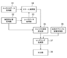
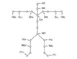
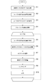
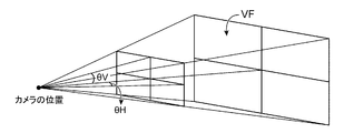
- FIG. 3 is a configuration block diagram showing an example of a display device connected to the information processing device according to the embodiment of the present invention. It is a functional block diagram showing the example of the information processing apparatus which concerns on embodiment of this invention. It is explanatory drawing showing the example of the bone model which the information processing apparatus which concerns on embodiment of this invention uses. It is a flowchart figure showing the operation example of the information processing apparatus which concerns on embodiment of this invention. It is explanatory drawing showing the example of the angle of view which the information processing apparatus which concerns on embodiment of this invention sets.
- the information processing apparatus 1 is, for example, a home-use game machine, and as illustrated in FIG. 1, a control unit 11, a storage unit 12, an operation receiving unit 13, and a display control unit 14. And a communication unit 15 and an image pickup unit 16. Further, the information processing device 1 is communicatively connected to a display device 2 such as a head mounted display (HMD) worn by a user on the head.
- a display device 2 such as a head mounted display (HMD) worn by a user on the head.
- HMD head mounted display
- an example of the display device 2 worn by the user on the head is a display device worn by the user on the head, and as illustrated in FIG. 2, the control unit 21 and the communication unit. 22 and a display unit 23.
- the control unit 21 of the display device 2 is a program control device such as a microcomputer, operates according to a program stored in a memory (not shown) such as a built-in storage unit, and communicates with the information processing device 1.
- An image corresponding to the information input via the unit 22 is displayed on the display unit 23 to allow the user to browse.
- the communication unit 22 is communicably connected to the information processing device 1 by wire or wirelessly.
- the communication unit 22 outputs the information transmitted from the information processing device 1 to the display device 2 to the control unit 21.
- the display unit 23 displays a video image corresponding to each of the right eye and the left eye of the user in front of each eye.
- the display unit 23 includes a display element such as an organic EL display panel or a liquid crystal display panel. This display element displays an image according to an instruction input from the control unit 21.
- the display element may be a single display element that displays the left-eye image and the right-eye image side by side in a row, or may be a pair of display elements that independently display the left-eye image and the right-eye image. It may be a display element.
- the display device 2 is a non-transmissive display device in which the user cannot visually recognize the appearance of the outside world.
- the control unit 11 of the information processing device 1 is a program control device such as a CPU and executes a program stored in the storage unit 12.
- the control unit 11 acquires character body size data representing a body size of a virtual character represented by a bone model including a plurality of nodes, and further, at a plurality of parts on the body of the user. Then, the position in the real space of the part corresponding to the node of this virtual character is estimated.
- the control unit 11 also acquires user body size data representing the body size of the user, and calculates a scaling coefficient based on the ratio of the user body size data to the character body size data.
- the control unit 11 determines, for at least some of the nodes included in the bone model of the virtual character, the position of the node in the virtual space, the estimated position of the body part of the user in the real space, and , A scaling factor is used to determine an image from a virtual camera arranged at a predetermined part on the virtual character, and the generated image is presented to a display device mounted on the user's head.
- a scaling factor is used to determine an image from a virtual camera arranged at a predetermined part on the virtual character, and the generated image is presented to a display device mounted on the user's head.
- the storage unit 12 is a memory device such as a RAM or a disk device, and stores the program executed by the control unit 11.
- the storage unit 12 also operates as a work memory of the control unit 11, and stores data used by the control unit 11 in the process of executing a program.
- the program may be stored in a computer-readable non-transitory recording medium, provided, and stored in the storage unit 12.
- the operation receiving unit 13 receives a user's instruction operation from the operation device C by wire or wirelessly.
- the operation device C is, for example, a controller of a home-use game machine.
- the operation receiving unit 13 outputs information indicating the content of the instruction operation performed by the user to the operation device C to the control unit 11.
- the display control unit 14 sends the input image data from the control unit 11 to the display device 2 via the communication unit 15.
- the display control unit 14 may be connected to a display or the like. In this case, the display control unit 14 sends the image to the display device 2 and causes the display to display an image of the viewpoint of the user wearing the display device 2.
- the communication unit 15 is communicably connected to the user's display device 2 in a wired or wireless manner.
- the communication unit 15 receives the information including the image data to be transmitted to the display device 2 from the display control unit 14 and outputs the information to the display device 2.
- the image pickup unit 16 is, for example, a stereo camera, and the angle of view and the direction of the image pickup are determined so that a plurality of cameras arranged at mutually distant positions can pick up the user.
- the image capturing unit 16 repeatedly captures the image of the user in the real space, and sends the captured image data to the control unit 11.
- control unit 11 of the information processing device 1 has a character data acquisition unit 31, a real space position acquisition unit 32, a user data acquisition unit 33, a scale calculation unit 34, and a character posture.
- the setting unit 35, the virtual object placement processing unit 36, the rendering processing unit 37, and the output unit 38 are functionally included.
- the character data acquisition unit 31 receives a selection of a virtual character represented by a bone model including a plurality of nodes from a user as a means for acquiring character body size data, and represents the body size of the selected virtual character.
- Acquire character body size data includes, for example, as illustrated in FIG. 4, a plurality of nodes and bones that connect a pair of nodes, and the nodes are the chest CH, the neck NK, and the head HE of the virtual character. , Shoulder SH, arm joint EL, hand joint (arm tip) HD, waist WT, hip joint HJ, knee NE, foot FT, and so on.
- the bone model in FIG. 4 is an example, and various widely known bone models can be adopted in the present embodiment.
- the character data acquisition unit 31 of the present embodiment acquires a predetermined bone model of a virtual character, information defining the appearance (polygon model, texture, etc.), and character body size data Hc representing the body size thereof. ..
- the character body size data Hc is the height of the node closest to the floor surface of the virtual character in the bone model, for example, the height FTh of the node of the foot FT and the height of the node farthest from the floor, for example, the node of the head HE.
- the height is expressed as follows. That is, the direction perpendicular to the floor in the virtual space in which the virtual character stands (the direction of the line segment where the coronal plane and the sagittal plane intersect when the character stands upright on the floor) is the Z axis, and upward from the floor. Is its positive direction.
- the axis extending in the front-rear direction is the Y axis
- the axis extending in the left-right direction of the virtual character in the initial state (the line segment that intersects the cross section and the coronal plane). Is the X axis.
- the front of the virtual character in the initial state is defined as the Y-axis positive direction
- the right-hand side of the character in the initial state is defined as the X-axis positive direction. It is assumed that the directions of the respective axes of the XYZ coordinate system (world coordinate system of virtual space) do not change even if the character moves thereafter.
- the height value of each part of the virtual character means the Z-axis value of the node coordinates when the node position is expressed in this XYZ coordinate system.
- the character data acquisition unit 31 acquires information such as a bone model related to a predetermined virtual character here, in the example of the present embodiment, the storage unit 12 of the information processing device 1 stores a plurality of information items. Information that defines the bone model and appearance of the virtual character, and the character body size data Hc may be stored. In this case, when the user selects one of them, the character data acquisition unit 31 acquires the bone model relating to the selected virtual character, information defining the appearance, and the character body size data Hc. In addition, data regarding these virtual characters may be acquired via a network.
- the real space position acquisition unit 32 realizes an example of a unit for acquiring user body size data, and is a plurality of parts on the user's body, and is a bone model of the virtual character acquired by the character data acquisition unit 31. Estimate the positions in real space of the parts corresponding to at least some of the nodes.
- the user's head (the center of the circumscribed rectangular parallelepiped surrounding the head, the same applies hereinafter), chest, tips of left and right arms (left and right hands), waist, and left and right legs (tips of legs).
- the position of each part in the real space will be detected.
- the real space position acquisition unit 32 realizes an example of means for acquiring the user body size data, and the real space position acquisition unit 32 obtains the real image obtained by the imaging unit 16 which is a stereo camera.
- Information representing the position of each part of the user is acquired from the image of the user in the space.
- the information representing the position of each part of the user in the real space is the coordinate of the world coordinate system (the orthogonal coordinate system of ⁇ ) in the real space with the origin of the predetermined reference point in the real space. It can be set as a value.
- the reference point of the world coordinate system may be set at a predetermined position on the floor on which the user stands, and the position coordinates of each part of the user are set as the values of the world coordinate system using the stereo camera of the user. Since a method of estimating and acquiring based on a captured image is widely known, detailed description thereof will be omitted here.
- a tracker that estimates the position of each part of the body of the user a method that the tracker device estimates the position independently by applying SLAM (Simultaneous Localization and Mapping) technology, as well as magnetism, IMU (inertial measurement device), GPS Any method such as (Global Positioning System) or a method using an RF tag may be used as long as the position coordinates of each part of the user in the real space can be acquired. Therefore, the imaging unit 16 is not always necessary depending on the method adopted.
- SLAM Simultaneous Localization and Mapping
- IMU intial measurement device
- GPS Any method such as (Global Positioning System) or a method using an RF tag may be used as long as the position coordinates of each part of the user in the real space can be acquired. Therefore, the imaging unit 16 is not always necessary depending on the method adopted.
- the user data acquisition unit 33 acquires user body size data Hu representing the user's body size as a means for acquiring user body size data.
- the user body size data Hu is the difference between the height of the user's head and the height of the user's feet when the user is upright on the floor.
- the height of each part is a value in the height direction of the user, and is specifically expressed by the value of the ⁇ -axis component of the coordinate value of each part in the world coordinate system.
- the information processing device 1 requests the user to temporarily stop in an upright pose, and acquires the position of the user's head and the position of the user's foot in that state.
- the user body size data Hu may be obtained from the information on these positions.
- the user data acquisition unit 33 repeatedly acquires a value (difference in height) corresponding to the user body size data Hu over a predetermined time, and sets the maximum value among the acquired values to the user body size data. It may be Hu. According to this, it is not always necessary to ask the user for a pose.
- the position of the user's foot may be estimated based on the image obtained by the image capturing unit 16 as the position of the user's foot, or the position of the floor surface instead of the actual position of the foot. May be the position of the foot.
- the user body size data Hu does not necessarily have to be the length corresponding to the height.
- it may be statistically the maximum distance between both hands (distance between both hands when both hands are open), which is known to be approximately equal to the height in humans.
- the information processing apparatus 1 instructs the user to take a pose with both hands open, estimates the positions of the left and right hands of the user in the real space at the time of the pose, and estimates the position of each hand.
- the user body size Hu is obtained by calculating the distance between the positions.
- the user data acquisition unit 33 repeatedly acquires a value (distance between the two hands) corresponding to the user body size data Hu over a predetermined time, and sets the maximum value among the acquired values as the user body size data Hu. Good.
- the character body size data Hc is also set as the maximum distance between both hands of the character (distance between both hands when the character has both hands open). You may leave it.
- the user data acquisition unit 33 is supposed to acquire the user body size data Hu based on the actual image of the user acquired by the real space position acquisition unit 32, but the present embodiment is not limited to this.
- the user data acquisition unit 33 may accept the input of the height of the user as numerical information by the operation of the user and use it as the user body size data Hu.
- the scale calculator 34 calculates the scaling coefficient Sr based on Hc/Hu, which is the ratio of the character body size data Hc to the user body size data Hu.
- Hc/Hu the ratio of the character body size data Hc to the user body size data Hu.
- the character posture setting unit 35 uses, as the character posture estimating means, the position of the node included in the bone model of the virtual character in the virtual space, the estimated position of the body part of the user in the real space, and the scaling coefficient. To decide. In one example of the present embodiment, the character posture setting unit 35 determines the position coordinates of all the nodes of the virtual character in the virtual space using the position of the user's body part in the real space and the scaling coefficient.
- the node of the part of the virtual character corresponding to the part of the user's body acquired by the real space position acquisition unit 32 is the selected node.
- the real space position acquisition unit 32 acquires the positions in the real space of the user's head, chest, left and right arm tips (left and right hands), waist, and left and right legs (leg tips) in the real space.
- the character posture setting unit 35 sets corresponding nodes (heads, chests, tips of left and right arms (left and right hands), waists, and left and right legs) in the virtual character as selection nodes.
- the positions of these selection nodes are determined using the positions of the body parts of the user in the real space and the scaling factors. This determination method will be described later.
- the character posture setting unit 35 determines the position of each node included in the bone model of the virtual character other than the selected node based on the determined position of the selected node. Since the positions of nodes other than the selected node can be determined by a widely known inverse kinematic method such as FABRIK (Forwards and Backwards Reaching Inverse Kinematics), description thereof will be omitted here.
- FABRIK Forwards and Backwards Reaching Inverse Kinematics
- the character posture setting unit 35 obtains the relative position of the corresponding user's body part from the reference point, multiplies the relative position by a scaling coefficient, and calculates the virtual character in the virtual space. The relative position of the selected node. Then, the coordinates of the selected node are obtained from the relative position and the coordinates of the reference point in the virtual space.
- the virtual object placement processing unit 36 places a virtually set object in the virtual space as a means for placing a virtual object.
- the object arranged in the virtual space may correspond to the real object arranged in the real space, or the corresponding real object may not exist.
- the virtual object placement processing unit 36 acquires the position of the wall in the real space and places the wall, which is a virtual object, at the corresponding position in the virtual space.
- the virtual object placement processing unit 36 causes an enemy character or the like, which is a virtual object, whose corresponding real object does not exist in the real space, into the virtual space by the processing of the game program or the like executed by the control unit 11. Deploy.
- the virtual object placement processing unit 36 also deforms and displays the polygon model of the virtual character acquired by the character data acquisition unit 31 based on the bone model for which the position of each node is determined by the character posture setting unit 35. Since the method of processing for controlling the posture of the virtual character in the virtual space by the bone model is widely known, the description thereof is omitted here.
- the rendering processing unit 37 renders and generates an image in the virtual space set by the virtual object placement processing unit 36.
- the rendering processing unit 37 is assumed to have a rendering camera at a predetermined portion (for example, the position of the head) of the virtual character, and the camera is in front of the virtual character (crosses the head).
- the angle of view is assumed to be predetermined.
- the rendering processing unit 37 generates each object in the virtual space (including each part of the virtual character itself) by rendering the image data when viewed from the camera set as described above.
- a widely known method can be adopted as such a rendering method.
- the output unit 38 sends the image data generated by the rendering processing unit 37 to the display device 2 worn by the user.
- the present embodiment has the above configuration and operates as follows. In the following description, it is assumed that the user selects and uses a virtual character used in the game in the virtual space. Further, in the following description, the world coordinate systems in the real space and the virtual space are assumed to be set in the same manner as the example already described.
- the information processing device 1 When the user operates the information processing device 1 to select a virtual character, the information processing device 1 starts the processing illustrated in FIG. 5, and the bone model of the virtual character and information defining the appearance (polygon model and texture). Etc.) and character body size data Hc representing the body size (S1).
- the information processing device 1 uses the user's image captured by the image capturing unit 16 in the real space to determine the user's head, chest, left and right arm tips (left and right hands), waist, and left and right legs (legs).
- the coordinate values in the real world world coordinate system (the rectangular coordinate system of ⁇ ) of each part) are repeatedly obtained at predetermined timings a plurality of times (S2).
- the information processing apparatus 1 also acquires user body size data Hu representing the user's body size (S3).
- the user body size data Hu may be obtained from the difference between the height of the user's head and the height of the user's feet when the user is upright on the floor.
- the information processing apparatus 1 repeatedly acquires a value (difference in height) corresponding to the user body size data Hu over a predetermined time, and sets the maximum value among the acquired values to the user.
- the body size data Hu may be used.
- the information processing device 1 starts the repeated processing (loop start), and from the image of the user in the real space captured by the imaging unit 16, the user's head, chest, and tips of the left and right arms (left and right). , Hand, waist, and left and right legs (tips of legs) in the real space in the world coordinate system (the orthogonal coordinate system of ⁇ ) is obtained (S5).
- the information processing apparatus 1 determines the position of the node included in the bone model of the virtual character in the virtual space, the position in the real space of the user's body part estimated in the processing S5, and the scaling coefficient obtained in the processing S4. It is determined using Sr (S6).
- the information processing apparatus 1 also determines the position of each node included in the bone model of the virtual character other than the selected node based on the position of the selected node determined above.
- the positions of nodes other than the selected node are determined by a well-known inverse kinematic method such as FABRIK (Forwards and Backwards Reaching Inverse Kinematics).
- the information processing device 1 further acquires the position of the wall in the real space, and arranges the wall, which is a virtual object, at the corresponding position in the virtual space. Further, the information processing apparatus 1 arranges the enemy character or the like, which is a virtual object, at the position designated by the game program in the virtual space by the processing of the running game program or the like (S7: object arrangement).
- the information processing apparatus 1 deforms and displays the polygon model of the virtual character based on the bone model whose position of each node is determined in the processes S5 and S6 (S8: virtual character arrangement).
- the information processing device 1 renders the image in the virtual space set in the processes S7 and S8 as image data viewed from a virtual camera arranged at a predetermined part (eg, head position) of the virtual character (S9). ). The direction and angle of view of the camera are set in a predetermined range in front of the virtual character.
- the information processing device 1 transmits the image data rendered here to the display device 2 mounted on the user's head to present the image data to the user (S10).
- the information processing device 1 repeatedly executes the processes S5 to S10 here while the game program is being executed. Thereby, the image data of the virtual space from the viewpoint of the virtual character is provided to the user, and if the user changes the pose, the pose of the virtual character is also set according to the change of the pose.
- the position of the node included in the bone model of the virtual character in the virtual space is used as the estimation result of the position of the user's body part in the real space and the body such as the height and arm length. Since it is determined using the scaling coefficient Sr related to the size ratio of the size of the character, the display position of the limbs of the character as seen from the head of the character is the position when the user looks at his/her limbs in the real space. Matches (angle from viewpoint).
- the positions of the nodes of each part of the character are determined by using the calculation by the inverse kinematic method based on the positions of some of the nodes of the character determined in this way.
- the positions of joints and the like other than the limbs as viewed from the head also substantially match the positions (angles) when the user looks at the corresponding joints and the like in the real space.
- the information processing apparatus 1 of the present embodiment as described above, it is possible to display without any discomfort regardless of the scale of the ratio between the actual body size of the user and the body size of the character.
- the feeling of immersion in the character can be improved.
- the object when an object such as a wall in the real space is displayed as a virtual object at a corresponding position in the virtual space based on the position information in the real space, the object The display position may be determined as follows.
- the information processing apparatus 1 executes the process illustrated in FIG. 5, but when determining the reference point in the real space and the reference point in the virtual space in the process S7, From the user's head (after moving) at the time of processing to the floor of the perpendicular line that is dropped from the user's head to the floor, the node of the head of the bone model of the virtual character in the virtual space is moved to the floor. The foot of the lowered perpendicular is used as the reference point in the virtual space.
- the information processing device 1 further acquires the position of an object such as a wall in the real space.
- the information processing device 1 acquires the coordinates of at least three vertices of a rectangular parallelepiped that circumscribes an object in the real space.
- the information processing device 1 converts the coordinates of these vertices into the relative coordinates from the reference point in the real space, multiplies the value of the relative coordinates by the scaling coefficient, and makes the relative coordinates from the reference point in the virtual space. Find the coordinates.
- the information processing device 1 converts the obtained relative coordinates of each vertex into coordinates from the origin in the virtual space, and determines that there is a vertex corresponding to the coordinates in the virtual space after the conversion, and determines that there is a vertex in the real space.
- a virtual object corresponding to the object is arranged (the polygon shape and position of the virtual object are set).
- the position where the virtual object is arranged in the virtual space is determined by using the position information of the object in the real space and the scaling coefficient.
- the scaling coefficient is smaller than “1”
- the distance between the virtual character and the wall is relative to the distance between the actual user and the wall.
- the scale factor is reduced by the ratio of the scaling factor, and the virtual character comes closer to the stride (which is assumed to be proportional to the height).
- the length of the user's arm does not actually change, so when calculating the relative coordinates of the virtual object in the virtual space, the values of the ⁇ and ⁇ axis components of the relative coordinate values in the real space are used to calculate the arm of the user. After subtracting the value corresponding to the length, the scaling coefficient may be multiplied, and the value corresponding to the arm length may be added to obtain the relative coordinates from the reference point in the virtual space.
- the distance between the user and the wall in the real space is dw and the length of the arm is la
- the length of the arm of the user may be designated by the user, or the length of the arm of the user in the real space may be determined based on the information of the positions of the multiple parts on the body of the user in the real space. May be estimated.
- This estimation may be, for example, the length of a general human arm with respect to the estimated height, or similar to the estimation of the height, the length from the chest to the tip of the arm repeatedly detected in step S2 of FIG. The maximum value of may be used.
- the control unit 11 of the present embodiment sets the angle of view of the camera to the arm of the bone model of the virtual character. You may determine using the information of length Wc.
- the arm length Wc of the bone model is set from the node of the head HE when the bone model is set upright on the floor and the arms are fully opened (so-called T pose state). It is defined as the shortest distance between the perpendicular line L dropped to the floor and the node at the tip of the arm (the distance from the node at the tip of the arm to the foot of the perpendicular dropped to the perpendicular L).
- the control unit 11 realizes a function related to an example of a unit for acquiring user body size data, and acquires information on the arm length Wu (arm length in real space) of the user.
- the length Wu of the arm of the user may also be designated by the user, or the length of the arm of the user in the real space may be specified based on the information on the positions of a plurality of parts on the body of the user in the real space. May be estimated. That is, similar to the above, the length of a general human arm with respect to the estimated height may be used, or, similarly to the estimation of the height, the length from the chest to the tip of the arm repeatedly detected in the process S2 of FIG. You may use the maximum value of the height.
- the control unit 11 determines the angle of view of the virtual rendering camera as follows.
- the predetermined angle of view is ⁇ .
- this angle of view means the apex angle of a range (so-called viewing frustum) VF captured by the camera, and includes a vertical angle of view ⁇ V and a horizontal angle of view ⁇ H.
- There is a default angle of view (the default angle of view in the vertical direction is ⁇ V0 and the default angle of view in the horizontal direction is ⁇ H0).
- the control unit 11 determines the angles of view ⁇ H and ⁇ V when rendering the image data of the virtual space from the viewpoint (head) of the virtual character, Or Stipulate.
- the angle of view is based on the arm length of the virtual character, and more specifically, the ratio of the arm length of the virtual character to the height of the virtual character, or the ratio of the arm length of the user to the height of the virtual character. It is controlled according to a value obtained by multiplying the ratio of the height of the user to the length.
- the longer length or the shorter one may be set as the arm length Wc of the virtual character.
- the arm length By setting the angle of view, image data in the virtual space is rendered as a visual field (extremely narrow visual field or extremely wide visual field) peculiar to the virtual character. As a result, it is possible to display the image without a sense of incongruity and improve the feeling of immersion in the character.
- the information processing apparatus 1 further changes the display position of the limbs of the character viewed from the head of the character by changing the length of the arm with respect to the height of the bone model of the virtual character to be used.
- the control may be performed so as to match the position (angle from the viewpoint) when the user looks at his/her limbs in space.
- the information processing device 1 copies the bone model to be used, and further sets the coordinate value of the node of the bone model to the next value.
- a corrected bone model is generated by performing correction as described above.
- the X coordinate value x of the coordinates (x, y) of each node belonging to the arm is set to a predetermined value.
- the correction coefficient is multiplied by.
- the correction coefficient is a ratio Hc between the height Hc of the virtual character and the length of both arms of the virtual character (the distance between the tips of both arms when the arms are fully extended to the left and right and a T pose is taken) Wc. /Wc (value when assuming that the height of the user is equal to the length of both arms) or the length Wu of both arms of the user and the height Hu (each of which is acquired as user body size data)
- a value obtained by multiplying the ratio may be (Hc/Wc) ⁇ (Wu/Hu).
- the information processing apparatus 1 draws a character using this corrected bone model.
- the length of both arms with respect to the height of the character is corrected by a value that takes into consideration the ratio of the height of the user to the length of both arms, the actual size of the user's body and the body of the character No matter what scale the size is, it is possible to display the image without any sense of discomfort and improve the immersive feeling of the character.
- the information processing apparatus 1 is supposed to generate an image displayed by a device such as an HMD mounted on the head of the user, but the present embodiment does not.
- the present invention is not limited to this, and can be applied even when an image displayed from a first-person viewpoint is displayed on a general display device such as a home TV. In this case, the processing of the display device 2 and the output thereto is not always necessary.
- 1 information processing device 2 display device, 11 control unit, 12 storage unit, 13 operation receiving unit, 14 display control unit, 15 communication unit, 16 imaging unit, 21 control unit, 22 communication unit, 23 display unit, 31 character data Acquisition unit, 32 real space position acquisition unit, 33 user data acquisition unit, 34 scale calculation unit, 35 character posture setting unit, 36 virtual object placement processing unit, 37 rendering processing unit, 38 output unit.
Landscapes
- Engineering & Computer Science (AREA)
- Theoretical Computer Science (AREA)
- Physics & Mathematics (AREA)
- General Physics & Mathematics (AREA)
- Multimedia (AREA)
- Computer Vision & Pattern Recognition (AREA)
- Computer Graphics (AREA)
- Geometry (AREA)
- Computing Systems (AREA)
- Human Computer Interaction (AREA)
- Architecture (AREA)
- Computer Hardware Design (AREA)
- General Engineering & Computer Science (AREA)
- Software Systems (AREA)
- Health & Medical Sciences (AREA)
- General Health & Medical Sciences (AREA)
- Psychiatry (AREA)
- Social Psychology (AREA)
- Processing Or Creating Images (AREA)
Abstract
ユーザに対して提示する、仮想空間の画像を生成する情報処理装置が、実空間中の対象物の位置の情報を検出し、検出した対象物の実空間中での位置の情報に基づいて求められる、仮想空間内の位置に、対象物に対応する仮想物体を配置し、ユーザの実空間内での身体のサイズを表すユーザ身体サイズデータを取得して、仮想空間内での仮想物体を配置する位置を、検出した対象物の実空間中での位置の情報と、実空間内でのユーザのユーザ身体サイズデータと、を用いて決定する。
Description
本発明は、情報処理装置、情報処理方法、及びプログラムに関する。
ユーザの身体の各部の予め定めた位置に、トラッカーと呼ばれるマーカーを取り付けて、これを外部から撮像し、マーカーの位置を推定するボディトラッキングの技術は広く知られている。
また、このボディトラッキングにより推定されたユーザの実際の身体の各部の位置に基づいて、ゲーム空間や、VR空間等の仮想的な空間内でのキャラクタの姿勢を決定し、その仮想的な頭部の位置や、手の位置などの情報を得て、さらにこれらの情報に基づき、仮想空間内でのキャラクタの身体の画像を生成する技術が知られている。またさらに、キャラクタの仮想空間内の視点の位置からの画像を生成してユーザに提示する(いわゆる第一者(First Person)視点)ことにより、仮想空間にユーザが入り込んだかのような、没入感のある画像を提示する技術が知られている。
このような従来の仮想空間の画像を表示する技術では、実空間でのユーザの移動や姿勢の変化に対応するため、仮想空間内におけるキャラクタの視点は、ユーザの実際の身長に対応するものとして設定される。しかしながら、キャラクタの身長等のサイズは、ユーザの実際の身長に関わりなく設定されているため、当該ゲームのキャラクタの身長が、ユーザの身長と大きく異なる場合にも、その視点はユーザの身長に対応する位置となってしまう。
さらに従来の技術では、第一者視点でありながら、キャラクタの手足と頭の位置との相対的位置関係がユーザ自身の手足と頭の位置との相対的位置関係とは異なるため、ユーザは、キャラクタの身体の動きが、自身の身体の動きと異なるという違和感を感じることとなっていた。
従来の仮想空間の画像を表示する技術では、このような要因等により、キャラクタへの没入感が低くなってしまうという問題があった。
本発明は上記実情に鑑みて為されたもので、キャラクタへの没入感を向上できる情報処理装置、情報処理方法、及びプログラムを提供することを、その目的の一つとする。
上記従来例の問題点を解決する本発明の一態様は、ユーザに対して提示する、仮想空間の画像を生成する情報処理装置であって、実空間中の対象物の位置の情報を検出する手段と、検出した前記対象物の実空間中での位置の情報に基づいて求められる、前記仮想空間内の位置に、前記対象物に対応する仮想物体を配置する手段と、前記ユーザの実空間内での身体のサイズを表すユーザ身体サイズデータを取得する手段と、前記仮想空間内での前記仮想物体を配置する位置を、前記検出した対象物の実空間中での位置の情報と、前記実空間内でのユーザのユーザ身体サイズデータと、を用いて決定する手段と、を含むこととしたものである。
本発明によると、キャラクタへの没入感を向上できる。
本発明の実施の形態について図面を参照しながら説明する。本発明の実施の形態に係る情報処理装置1は、例えば家庭用ゲーム機であり、図1に例示するように、制御部11と、記憶部12と、操作受入部13と、表示制御部14と、通信部15と、撮像部16とを含んで構成される。またこの情報処理装置1は、ユーザが頭部に装着するヘッドマウントディスプレイ(HMD)などの表示装置2との間で通信可能に接続されている。
本実施の形態においてユーザが頭部に装着する表示装置2の一例は、ユーザが頭部に装着して使用する表示デバイスであって、図2に例示するように、制御部21と、通信部22と、表示部23とを含む。ここでの例では表示装置2の制御部21は、マイクロコンピュータ等のプログラム制御デバイスであって、内蔵する記憶部等の図示しないメモリ等に格納されたプログラムに従って動作し、情報処理装置1から通信部22を介して入力される情報に応じた映像を表示部23に表示させて、ユーザに閲覧させる。通信部22は、有線または無線にて情報処理装置1との間で通信可能に接続される。通信部22は、情報処理装置1から表示装置2宛に送信された情報を、制御部21に出力する。表示部23は、ユーザの右目と左目とのそれぞれの目の前に、それぞれの目に対応した映像を表示するものとする。この表示部23は、有機EL表示パネルや液晶表示パネルなどの表示素子を含む。この表示素子が制御部21から入力される指示に従って映像を表示する。この表示素子は、左目用の映像と右目用の映像とを一列に並べて表示する1つの表示素子であってもよいし、左目用の映像と右目用の映像とをそれぞれ独立に表示する一対の表示素子であってもよい。なお、本実施形態においてこの表示装置2は、ユーザが外界の様子を視認することができない非透過型の表示装置である。
また情報処理装置1の制御部11は、CPU等のプログラム制御デバイスであり、記憶部12に格納されているプログラムを実行する。本実施の形態では、この制御部11は、複数のノードを含むボーンモデルで表される仮想キャラクタの、身体サイズを表すキャラクタ身体サイズデータを取得し、さらに、ユーザの身体上の複数の部位であって、この仮想キャラクタのノードに対応する部位の実空間中の位置を推定する。また制御部11は、ユーザの身体サイズを表すユーザ身体サイズデータを取得して、このユーザ身体サイズデータと、キャラクタ身体サイズデータとの比に基づいてスケーリング係数を演算する。
制御部11は、そして、仮想キャラクタのボーンモデルに含まれるノードの少なくとも一部のノードについて、当該ノードの仮想空間内での位置を、推定されたユーザの身体部位の実空間中の位置、及び、スケーリング係数を用いて決定し、当該仮想キャラクタ上の所定部位に配した仮想的なカメラからの画像を生成してユーザの頭部に装着された表示装置に当該生成した画像を提示させる。この制御部11の動作については後に詳しく述べる。
記憶部12は、RAM等のメモリデバイスやディスクデバイス等であり、制御部11が実行するプログラムを格納する。また、この記憶部12は制御部11のワークメモリとしても動作し、制御部11がプログラム実行の過程で使用するデータを格納する。このプログラムは、コンピュータ可読かつ非一時的な記録媒体に格納されて提供され、この記憶部12に格納されたものであってもよい。
操作受入部13は、操作デバイスCからユーザの指示操作を有線または無線にて受け入れる。ここで操作デバイスCは例えば、家庭用ゲーム機のコントローラ等である。操作受入部13はユーザが操作デバイスCに対して行った指示操作の内容を表す情報を、制御部11に出力する。
表示制御部14は、制御部11から、入力された画像データを、通信部15を介して表示装置2宛に送出する。またこの表示制御部14は、ディスプレイ等に接続されてもよく、この場合は、表示装置2宛に送出するとともに、ディスプレイには、表示装置2を装着したユーザの視点の画像を表示させる。
通信部15は、有線または無線にてユーザの表示装置2との間で通信可能に接続される。この通信部15は、表示制御部14から表示装置2宛に送信する画像データを含む情報を受け入れて、当該情報を、表示装置2に出力する。
撮像部16は、例えばステレオカメラ等であり、互いに離れた場所に配された複数のカメラがいずれもユーザを撮像するよう、その画角と撮像の方向とが定められたものである。この撮像部16は、実空間でのユーザの画像を繰り返し撮像し、撮像して得た画像データを制御部11に送出する。
ここで情報処理装置1の制御部11の動作について説明する。本実施の形態の制御部11は、一例として図3に例示するように、キャラクタデータ取得部31と、実空間位置取得部32と、ユーザデータ取得部33と、スケール演算部34と、キャラクタ姿勢設定部35と、仮想オブジェクト配置処理部36と、レンダリング処理部37と、出力部38とを機能的に含んで構成される。
キャラクタデータ取得部31は、キャラクタ身体サイズデータを取得する手段として、複数のノードを含むボーンモデルで表される仮想キャラクタの選択を、ユーザから受けて、当該選択された仮想キャラクタの身体サイズを表すキャラクタ身体サイズデータを取得する。ここでボーンモデルは、例えば図4に例示するように、複数のノードと、一対のノード間を接続するボーンとを含むものであり、ノードは、仮想キャラクタの胸部CH、頚部NK、頭部HE、肩部SH、腕関節部EL、手関節部(腕先端)HD、腰部WT、股関節部HJ、膝部NE、足部FT…などの各部に対応する位置に配されるものとする。なお、図4のボーンモデルは一例であり、本実施の形態では、広く知られた種々のボーンモデルを採用し得る。
本実施の形態のキャラクタデータ取得部31は、予め定められた仮想キャラクタのボーンモデルや、外観を規定する情報(ポリゴンモデルやテクスチャなど)並びに、その身体サイズを表すキャラクタ身体サイズデータHcを取得する。ここでキャラクタ身体サイズデータHcは、ボーンモデルにおける仮想キャラクタの床面に最も近いノード、例えば足部FTのノードの高さFThと、床面から最も遠いノード、例えば頭部HEのノードの高さHEhの差HEh-FThで表される(Hc=HEh-FTh)。
ここで高さは次のように表される。すなわち、仮想キャラクタの立つ仮想空間内の床面に垂直な方向(キャラクタが床面に直立したときの冠状面と矢状面とが交差する線分の方向)をZ軸とし、床面から上方をその正の向きとする。また、この仮想空間内の床面がZ=0の平面であるとして、床面に平行な軸であって、キャラクタが初期状態(体を動かしていない状態)にあるときの、当該仮想キャラクタの前後方向に向かう軸(横断面と矢状面との交差する線分の方向)をY軸、当該初期状態での仮想キャラクタの左右方向に向かう軸(横断面と冠状面との交差する線分の方向)をX軸とする。また、初期状態での仮想キャラクタの前方をY軸正の方向、初期状態でのキャラクタから見た右手側をX軸正の方向とする。このXYZ座標系(仮想空間のワールド座標系)の各軸の方向は、この後、キャラクタが移動しても変化しないものとする。
そしてこの場合、仮想キャラクタの各部位の高さの値は、このXYZ座標系でノードの位置を表したとき、ノードの座標のZ軸の値を意味する。
なお、ここではキャラクタデータ取得部31は、予め定められた仮想キャラクタに関するボーンモデル等の情報を取得することとしたが、本実施の形態の一例では、情報処理装置1の記憶部12には複数の仮想キャラクタに関するボーンモデルや外観を規定する情報、並びにキャラクタ身体サイズデータHcが格納されていてもよい。この場合、ユーザがそのうち一つを選択すると、キャラクタデータ取得部31は、当該選択された仮想キャラクタに関するボーンモデルや、外観を規定する情報、並びに、そのキャラクタ身体サイズデータHcを取得する。また、これらの仮想キャラクタに関するデータは、ネットワークを介して取得されてもよい。
実空間位置取得部32は、ユーザ身体サイズデータを取得する手段の一例を実現するものであり、ユーザの身体上の複数の部位であって、キャラクタデータ取得部31が取得した仮想キャラクタのボーンモデルの少なくとも一部のノードに対応する部位の、実空間中の位置を推定する。
本実施の形態の一例では、ユーザの頭部(頭部を取り囲む外接直方体の中心、以下同じ)、胸部、左右の腕の先端(左右の手)、腰部、及び左右の足(脚の先端)の各部位の実空間中の位置を検出することとする。また本実施の形態の例では、この実空間位置取得部32は、ユーザ身体サイズデータを取得する手段の一例を実現するものであり、ステレオカメラである撮像部16が撮像して得た、実空間でのユーザの画像から、上記ユーザの各部位の位置を表す情報を取得する。ここで、実空間でのユーザの各部位の位置を表す情報は、実空間内の所定の基準点を原点とした実空間でのワールド座標系(ξηζの直交座標系とする)での座標の値として定めることができる。
ここでワールド座標系の基準点は、ユーザが立つ床面の所定の位置に設定すればよく、またこのようなワールド座標系の値として、ユーザの各部位の位置座標を、ユーザをステレオカメラで撮像した画像に基づいて推定して取得する方法は、広く知られているので、ここでの詳しい説明は省略する。
なお、ここではステレオカメラにて撮像した画像に基づいてユーザの身体の部位部位の位置を検出する例としているが、本実施の形態はこれに限られず、トラッカーデバイス等からレーザーなどを照射してユーザの身体の各部位の位置を推定するトラッカーや、SLAM(Simultaneous Localization and Mapping)技術を応用してトラッカーデバイスが自立的に位置を推定する方法、さらには磁気やIMU(慣性計測装置)、GPS(Global Positioning System)やRFタグを利用する方法等、実空間でのユーザの各部位の位置座標が取得できれば、どのような方法を採用しても構わない。従って、採用する方法によっては、撮像部16は、必ずしも必要なものではない。
ユーザデータ取得部33は、ユーザ身体サイズデータを取得する手段として、ユーザの身体サイズを表すユーザ身体サイズデータHuを取得する。具体的に、このユーザ身体サイズデータHuは、ユーザが床面に直立した状態にあるときの、ユーザの頭部の高さと、ユーザの足の高さとの差とする。ここで各部位の高さは、ユーザの身長方向の値であり、具体的には各部位のワールド座標系における座標値のζ軸成分の値によって表される。
また本実施の形態では、情報処理装置1は、ユーザに対して直立したポーズで一時的に静止することを求め、その状態でのユーザの頭部の位置とユーザの足の位置とを取得し、これらの位置の情報から、ユーザ身体サイズデータHuを得てもよい。また、このユーザデータ取得部33は、ユーザ身体サイズデータHuに相当する値(上記高さの差)を所定の時間に亘って繰り返し取得し、取得した値のうち最大の値をユーザ身体サイズデータHuとしてもよい。これによれば、必ずしもユーザにポーズを求める必要がなくなる。
なお、ここでユーザの足の位置は、ユーザの実際の足の位置を、撮像部16が得た画像に基づいて推定してもよいし、実際の足の位置の代わりに、床面の位置を足の位置としてもよい。
さらに、ここではユーザの頭部の位置と足の位置とを取得する例としたが、ユーザ身体サイズデータHuは、必ずしも身長に相当する長さでなくてもよい。例えば統計的に、人間では身長に概ね等しくなることが知られている、両手間の最大距離(両手を広げた状態での両手間の距離)であってもよい。この場合、情報処理装置1は、ユーザに両手を広げたポーズを取るよう指示し、当該ポーズとなったときのユーザの左右の手の位置の実空間中の位置を推定し、その各手の位置間の距離を演算することにより、ユーザ身体サイズHuを得る。また、ユーザデータ取得部33はユーザ身体サイズデータHuに相当する値(上記両手間の距離)を所定の時間に亘って繰り返し取得し、取得した値のうち最大の値をユーザ身体サイズデータHuとしてもよい。
なお、ユーザ身体サイズデータHuを、ユーザの両手間の最大距離とする場合は、キャラクタ身体サイズデータHcもキャラクタの両手間の最大距離(キャラクタが両手を広げた状態での両手間の距離)としておくこととしてもよい。
さらにここではユーザデータ取得部33は、実空間位置取得部32が取得したユーザの実際の画像に基づいてユーザ身体サイズデータHuを取得することとしたが、本実施の形態はこれに限られず、ユーザデータ取得部33は、ユーザの操作により、当該ユーザの身長の入力を数値情報として受け入れて、ユーザ身体サイズデータHuとしてもよい。
スケール演算部34は、スケール演算手段として、ユーザ身体サイズデータHuに対するキャラクタ身体サイズデータHcの比、Hc/Huに基づいてスケーリング係数Srを演算する。ここではスケール演算部34は、この比そのものをスケーリング係数Srとする。すなわち、Sr=Hc/Huであるものとする。
キャラクタ姿勢設定部35は、キャラクタ姿勢推定手段として、仮想キャラクタのボーンモデルに含まれるノードの仮想空間内での位置を、推定されたユーザの身体部位の実空間中の位置と、スケーリング係数を用いて決定する。本実施の形態の一例では、このキャラクタ姿勢設定部35がユーザの身体部位の実空間中の位置と、スケーリング係数を用いて、仮想キャラクタの上記ノードの全ての仮想空間内での位置座標を決定する必要は必ずしもなく、仮想キャラクタのボーンモデルに含まれるノードのうち、予め選択された選択ノードの仮想空間内での位置を、上記推定されたユーザの身体部位の実空間中の位置、及び、スケーリング係数を用いて決定し、次に、当該決定された選択ノードの仮想空間内での位置に基づいて当該選択ノード以外の、仮想キャラクタのボーンモデルに含まれる各ノードの位置を決定することとしてもよい。
本実施の形態のここでの例では、実空間位置取得部32が取得するユーザの体の部位に対応する仮想キャラクタの部位のノードを選択ノードとする。一例として、実空間位置取得部32がユーザの頭部、胸部、左右の腕の先端(左右の手)、腰部、及び左右の足(脚の先端)の各部位の実空間中の位置を取得する場合、キャラクタ姿勢設定部35は、仮想キャラクタにおける、対応するノード(頭部、胸部、左右の腕の先端(左右の手)、腰部、及び左右の足に対応するノード)を選択ノードとして、これら選択ノードの位置を、ユーザの身体部位の実空間中の位置と、スケーリング係数を用いて決定する。この決定方法については後に説明する。
そしてキャラクタ姿勢設定部35は、当該選択ノード以外の、仮想キャラクタのボーンモデルに含まれる各ノードの位置を、上記決定された選択ノードの位置に基づいて決定する。この選択ノード以外のノードの位置の決定は、FABRIK(Forwards and Backwards Reaching Inverse Kinematics)などの、広く知られた逆運動学的方法により行うことができるので、ここでの説明は省略する。
ここで選択ノードの位置の決定方法について説明する。本実施の形態では、キャラクタ姿勢設定部35は、選択ノードの位置を、次のようにして定める。すなわち、本実施の形態では、実空間のワールド座標系と仮想空間のワールド座標系とは原点とスケールとを一致させたものとして、キャラクタ姿勢設定部35が、ユーザ及び仮想キャラクタの頭部(仮想キャラクタについては頭部ノード)の位置からそれぞれ実空間と仮想空間の床面に下ろした垂線が、それぞれ対応する床面と交差する実空間及び、仮想空間の点の座標(ξ0,η0,ζ0),(x0,y0,z0)を基準点として、それぞれ実空間でのユーザの頭部の座標(ξHE,ηHE,ζHE)を用いて、(ξ0,η0,ζ0)=(ξHE,ηHE,0)、(x0,y0,z0)=(xHE,yHE,0)と設定する(既に述べたように、ここでの例では床面上に原点を設定しているため、ζ0=0、z0=0となる)。
キャラクタ姿勢設定部35は、実空間位置取得部32が得た、ユーザの各部位の座標値を、ここで求めた基準点(実空間内の基準点)からの相対的位置に変換する。例えばキャラクタ姿勢設定部35は、ユーザの右手の相対的位置(ξrRH,ηrRH,ζrRH)を、実空間位置取得部32が得たユーザの右手の位置(ξRH,ηRH,ζRH)を用いて、(ξrRH,ηrRH,ζrRH)=(ξRH-ξ0,ηRH-η0,ζRH-ζ0)と求める。キャラクタ姿勢設定部35は、このようにして、ユーザの頭部、胸部、左右の腕の先端(左右の手)、腰部、及び左右の足(脚の先端)の各部位の、上記基準点からの相対的位置を求める。
キャラクタ姿勢設定部35は、仮想空間内の仮想キャラクタのボーンモデルの、上記ユーザの各部位に対応するノードの相対的位置Nrを、対応する実空間でのユーザの部位の相対的位置の情報Prとスケーリング係数Srとを用いて、Nr=Sr×Prとして求める。例えば仮想空間内の仮想キャラクタの右手に対応するボーンモデルのノードの相対的位置の座標(xrRH,yrRH,zrRH)を、(xrRH,yrRH,zrRH)=(ξrRH×Sr,ηrRH×Sr,ζrRH×Sr)とする。
キャラクタ姿勢設定部35は、仮想空間内の仮想キャラクタのボーンモデルの、上記ユーザの各部位に対応するノードの相対的位置Nrを、仮想空間内に設定した原点からの座標に変換して、選択ノードの座標値(x,y,z)を決定する。すなわち、上記の例であれば、仮想空間内の仮想キャラクタの右手に対応するボーンモデルのノードの座標値(xRH,yRH,zRH)を、(xRH,yRH,zRH)=(xrRH+x0,yrRH+y0,zrRH+z0)とする。
キャラクタ姿勢設定部35は、他の選択ノードについても同様に、対応するユーザの部位の基準点からの相対的位置を求め、当該相対的位置にスケーリング係数を乗じて、仮想空間内における仮想キャラクタの選択ノードの相対的位置とする。そして当該選択ノードの座標を、相対的位置と仮想空間内の基準点の座標とから求める。
仮想オブジェクト配置処理部36は、仮想物体を配置する手段として、仮想的に設定されたオブジェクトを仮想空間内に配置する。ここで仮想空間内に配置されるオブジェクトは、実空間内に配された実オブジェクトに対応するものであってもよいし、対応する実オブジェクトは存在しなくてもよい。
例えば、この仮想オブジェクト配置処理部36は、実空間内にある壁の位置を取得し、仮想空間内の対応する位置に、仮想的なオブジェクトである壁を配置する。また仮想オブジェクト配置処理部36は、制御部11が実行するゲームプログラム等の処理により、実空間内には対応する実オブジェクトが存在しない、仮想的なオブジェクトである敵キャラクタ等を、仮想空間内に配置する。
またこの仮想オブジェクト配置処理部36は、キャラクタデータ取得部31が取得した仮想キャラクタのポリゴンモデルを、キャラクタ姿勢設定部35が各ノードの位置を決定したボーンモデルに基づいて変形して表示する。このようにボーンモデルにより仮想空間内での仮想キャラクタの姿勢を制御する処理の方法は広く知られているので、ここでの説明は省略する。
レンダリング処理部37は、仮想オブジェクト配置処理部36が設定した仮想空間内の画像をレンダリングして生成する。本実施の形態の一例では、このレンダリング処理部37は、仮想キャラクタの所定の部位(例えば頭部の位置)にレンダリング用のカメラがあるものとし、このカメラは仮想キャラクタの前方(頭部を横断する冠状面の法線方向であって、顔のある側)を向いているものとする。またその画角は、予め定められているものとする。
レンダリング処理部37は、仮想空間内の各オブジェクト(仮想キャラクタ自身の各部を含む)を、上記のように設定されたカメラから見たときの画像データをレンダリングして生成する。このようなレンダリングの方法についても広く知られた方法を採用できる。
出力部38は、レンダリング処理部37が生成した画像データを、ユーザが装着する表示装置2に対して送出する。
[動作]
本実施の形態は、以上の構成を備えており、次のように動作する。以下の説明では、ゲーム中で利用する、仮想空間内の仮想キャラクタをユーザが選択して用いるものとする。また以下の説明で、実空間及び仮想空間のワールド座標系は、既に説明した例と同様に設定されるものとする。
本実施の形態は、以上の構成を備えており、次のように動作する。以下の説明では、ゲーム中で利用する、仮想空間内の仮想キャラクタをユーザが選択して用いるものとする。また以下の説明で、実空間及び仮想空間のワールド座標系は、既に説明した例と同様に設定されるものとする。
ユーザが情報処理装置1を操作して仮想キャラクタを選択すると、情報処理装置1は、図5に例示する処理を開始し、当該仮想キャラクタのボーンモデルや、外観を規定する情報(ポリゴンモデルやテクスチャなど)並びに、その身体サイズを表すキャラクタ身体サイズデータHcを取得する(S1)。
なおキャラクタ身体サイズデータHcは、仮想キャラクタのボーンモデルのうち、足部FTのノードの高さFThと、頭部HEのノードの高さHEhの差として、つまり、Hc=HEh-FThとして演算されてもよい。
また情報処理装置1は、撮像部16にて撮像した、実空間でのユーザの画像から、ユーザの頭部、胸部、左右の腕の先端(左右の手)、腰部、及び左右の足(脚の先端)の各部位の実空間のワールド座標系(ξηζの直交座標系とする)での座標の値を所定のタイミングごとに複数回繰り返し求める(S2)。
また情報処理装置1は、ユーザの身体サイズを表すユーザ身体サイズデータHuを取得する(S3)。具体的に、このユーザ身体サイズデータHuは、ユーザが床面に直立した状態にあるときの、ユーザの頭部の高さと、ユーザの足の高さとの差により求めてもよい。既に述べたように、例えば情報処理装置1は、ユーザ身体サイズデータHuに相当する値(上記高さの差)を所定の時間に亘って繰り返し取得し、取得した値のうち最大の値をユーザ身体サイズデータHuとすればよい。
情報処理装置1は、ユーザ身体サイズデータHuに対するキャラクタ身体サイズデータHcの比、Hc/Huをスケーリング係数Sr(Sr=Hc/Hu)として求める(S4)。
以下、情報処理装置1は、繰り返しの処理を開始し(ループ始)、撮像部16にて撮像した、実空間でのユーザの画像から、ユーザの頭部、胸部、左右の腕の先端(左右の手)、腰部、及び左右の足(脚の先端)の各部位の実空間のワールド座標系(ξηζの直交座標系とする)での座標の値を求める(S5)。
そして情報処理装置1は、仮想キャラクタのボーンモデルに含まれるノードの仮想空間内での位置を、処理S5で推定されたユーザの身体部位の実空間中の位置と、処理S4で求めたスケーリング係数Srを用いて決定する(S6)。
具体的に情報処理装置1は、処理S5で実空間中の位置を取得した、ユーザの各部位に対応する、仮想キャラクタのボーンモデルのノードを選択ノードとする。そして情報処理装置1は、処理S5で得たユーザの頭部の位置から床面に下ろした垂線が、床面と交差する実空間の座標(ξ0,η0,ζ0)=(ξHE,ηHE,0)と、仮想キャラクタの頭部のノードから床面に下ろした垂線が、床面と交差する仮想空間の点の座標(x0,y0,z0)=(xHE,yHE,0)とを求め、それぞれ実空間と仮想空間とにおける基準点とする。
情報処理装置1は、処理S5で得たユーザの各部位の座標値を、ここで求めた基準点(実空間内の基準点)からの相対的位置に変換する。また、情報処理装置1は、仮想空間内の仮想キャラクタのボーンモデルの、上記ユーザの各部位に対応するノードの相対的位置Nrを、対応する実空間でのユーザの部位の相対的位置の情報Prとスケーリング係数Srとを用いて、Nr=Sr×Prとして求める。そして情報処理装置1は、仮想空間内の仮想キャラクタのボーンモデルの、上記ユーザの各部位に対応するノードの相対的位置Nr(基準点を原点とした座標系での値)を、仮想空間内に設定した原点からの座標値に変換して、各選択ノードの座標値(x,y,z)を決定する。
また情報処理装置1は、選択ノード以外の、仮想キャラクタのボーンモデルに含まれる各ノードの位置を、上記決定された選択ノードの位置に基づいて決定する。この選択ノード以外のノードの位置の決定は、FABRIK(Forwards and Backwards Reaching Inverse Kinematics)などの、広く知られた逆運動学的方法により行うこととする。
情報処理装置1は、さらに実空間内にある壁の位置を取得し、仮想空間内の対応する位置に、仮想的なオブジェクトである壁を配置する。また情報処理装置1は、実行しているゲームプログラム等の処理により、仮想的なオブジェクトである敵キャラクタ等を、仮想空間内のゲームプログラムにより指示された位置に配置する(S7:オブジェクト配置)。
そして情報処理装置1は、仮想キャラクタのポリゴンモデルを、処理S5,S6で各ノードの位置を決定したボーンモデルに基づいて変形して表示する(S8:仮想キャラクタ配置)。
情報処理装置1は、処理S7,S8で設定した仮想空間内の画像を、仮想キャラクタの所定の部位(例えば頭部の位置)に配した仮想的なカメラから見た画像データとしてレンダリングする(S9)。なお、このカメラの方向・画角は、仮想キャラクタの前方の予め定められた範囲とする。情報処理装置1は、ここでレンダリングした画像データをユーザの頭部に装着された表示装置2に送信して、ユーザに提示させる(S10)。
情報処理装置1は、ゲームプログラムの実行中は、ここでの処理S5からS10を繰り返して実行する。これにより仮想キャラクタの視点からの仮想空間の画像データがユーザに提供され、また、ユーザがポーズを変化させれば、当該ポーズの変化に応じて仮想キャラクタのポーズも設定される。
このとき、仮想キャラクタがユーザの身長よりも低い身長であれば、ユーザは当該低い身長からの視点で、仮想空間内の画像を見ることができる。また、本実施の形態では、仮想キャラクタのボーンモデルに含まれるノードの仮想空間内での位置を、ユーザの身体部位の実空間中の位置の推定結果と、身長や腕の長さなどの身体のサイズの比に関わるスケーリング係数Srとを用いて決定しているため、キャラクタの頭部から見た、キャラクタの手足の表示位置が、実空間中でユーザが自分の手足を見たときの位置(視点からの角度)に一致する。また、さらに本実施の形態では、このように決定したキャラクタの一部のノードの位置に基づく逆運動学的方法による演算を用いて、キャラクタの各部のノードの位置が決定されるため、キャラクタの頭部から見た、手足以外の関節等の位置も、実空間中でユーザが対応する関節等を見たときの位置(角度)に概ね一致することとなる。このような本実施の形態の情報処理装置1によると、ユーザの実際の身体のサイズと、キャラクタの身体のサイズとの比がどのようなスケールであっても、違和感のない表示が可能となり、キャラクタへの没入感を向上できる。
[ユーザの移動]
また、ユーザが表示装置2を装着したまま移動することを許容する場合、ユーザが仮想空間内で認識している身長に対して、ユーザの現実空間の移動量に応じた仮想空間内での移動量をそのまま用いると(スケーリング係数を考慮しないと)、身長に対する移動量が大きすぎるように感じられてしまう。また、本実施の形態の上記の例では、移動後の足の位置の検出結果も、実空間の移動量と異なってしまうこととなる。
また、ユーザが表示装置2を装着したまま移動することを許容する場合、ユーザが仮想空間内で認識している身長に対して、ユーザの現実空間の移動量に応じた仮想空間内での移動量をそのまま用いると(スケーリング係数を考慮しないと)、身長に対する移動量が大きすぎるように感じられてしまう。また、本実施の形態の上記の例では、移動後の足の位置の検出結果も、実空間の移動量と異なってしまうこととなる。
そこで本実施の形態では、実空間中の壁等の対象物を、その実空間中での位置の情報に基づいて、仮想空間内の対応する位置に仮想的なオブジェクトとして表示する場合、当該オブジェクトの表示位置を次のように決定してもよい。
このようにユーザが移動する場合も、情報処理装置1は、図5に例示した処理を実行するが、処理S7において実空間内の基準点と、仮想空間内の基準点とを定める際に、処理の時点での(移動した後の)ユーザの頭部から床面に下ろした垂線の足を実空間内の基準点とし、仮想空間における仮想キャラクタのボーンモデルの頭部のノードから床面に下ろした垂線の足を仮想空間内の基準点とする。
そして、情報処理装置1は、さらに実空間内にある壁等の対象物の位置を取得する。例えば情報処理装置1は、実空間内の対象物に外接する直方体の少なくとも3つの頂点の座標を取得する。そして情報処理装置1は、これらの頂点の座標を、実空間内の基準点からの相対座標に変換し、この相対座標の値を、スケーリング係数倍して、仮想空間内の基準点からの相対座標を求める。情報処理装置1は求められた各頂点の相対座標を、仮想空間内の原点からの座標に変換して、当該変換後の仮想空間内の座標に対応する頂点があるものとして、実空間内の対象物に対応する、仮想的なオブジェクトを配置する(仮想的なオブジェクトのポリゴンの形状やその位置等を設定する)。
このように本実施の形態の一例では、実空間中での対象物の位置の情報に基づいて求められる、仮想空間内の位置に、対象物に対応する仮想的なオブジェクトを配置するにあたり、当該仮想空間内での仮想的なオブジェクトを配置する位置を、対象物の実空間中での位置の情報と、スケーリング係数とを用いて決定する。
この例によると、仮想キャラクタの身長が、実際のユーザの身長より低い(スケーリング係数が「1」より小さい)とき、例えば仮想キャラクタと壁との距離は、実際のユーザと壁との距離に対して当該スケーリング係数の割合だけ短縮され、仮想キャラクタの歩幅(身長に比例すると仮定される)に合わせて近接することとなる。これにより、ユーザが壁に触れる位置まで移動したとき、仮想キャラクタから見た画像データにおいても、仮想キャラクタが壁に触れる位置まで移動した状態となって違和感が軽減される。
なお、実際にはユーザの腕の長さは変化しないので、仮想空間における仮想オブジェクトの相対座標を演算する際に、実空間の相対座標値のξ,η軸成分の値からそれぞれユーザの腕の長さに相当する値を差引きした後、スケーリング係数倍し、さらに上記腕の長さに相当する値を加算して、仮想空間内の基準点からの相対座標を求めてもよい。
この例では、例えばユーザと壁までの実空間での距離をdwとし、腕の長さをlaとしたとき、仮想空間での壁と仮想キャラクタとの距離dw′が、
dw′=Sr×(dw-Sr×la)+Sr×la
として演算されることとなる。
dw′=Sr×(dw-Sr×la)+Sr×la
として演算されることとなる。
ここでユーザの腕の長さは、ユーザから指定されてもよいし、ユーザの身体上の複数の部位の実空間中の位置の情報に基づいて、当該ユーザの実空間内での腕の長さを推定することとしてもよい。この推定は、例えば推定された身長に対する一般的な人間の腕の長さとしてもよいし、身長の推定と同様、図5の処理S2において繰り返し検出された、胸部から腕の先端までの長さの最大値を用いてもよい。
[視野角]
さらに、本実施の形態の制御部11は、仮想キャラクタ上の所定部位に配した仮想的なカメラからの画像データをレンダリングする際に、当該カメラの画角を、仮想キャラクタのボーンモデルの腕の長さWcの情報を用いて決定してもよい。
さらに、本実施の形態の制御部11は、仮想キャラクタ上の所定部位に配した仮想的なカメラからの画像データをレンダリングする際に、当該カメラの画角を、仮想キャラクタのボーンモデルの腕の長さWcの情報を用いて決定してもよい。
ここで、ボーンモデルの腕の長さWcは、ボーンモデルを床面に直立した状態に設定し、腕を一杯に広げた状態(いわゆるTポーズの状態)としたとき、頭部HEのノードから床面に対して下ろした垂線Lと、腕部の先端のノードとの最短距離(腕部の先端のノードから垂線Lに下ろした垂線の足までの距離)として規定する。
制御部11は、ユーザ身体サイズデータを取得する手段の一例に係る機能を実現するものであり、ユーザの腕の長さWu(実空間での腕の長さ)の情報を取得しておく。このユーザの腕の長さWuも、ユーザから指定されてもよいし、ユーザの身体上の複数の部位の実空間中の位置の情報に基づいて、当該ユーザの実空間内での腕の長さを推定することとしてもよい。つまり、上述と同様、推定された身長に対する一般的な人間の腕の長さとしてもよいし、身長の推定と同様、図5の処理S2において繰り返し検出された、胸部から腕の先端までの長さの最大値を用いてもよい。
そして制御部11は、仮想空間内の画像をレンダリングする際に、その仮想的なレンダリング用のカメラの画角を次のように定める。ここで予め定められた画角をθとする。この画角は、図6に例示するように、カメラが撮像する範囲(いわゆる視錐台(viewing frustum)VFの頂角を意味し、鉛直方向の画角θVと、水平方向の画角θHとがあり、予めデフォルトの画角(鉛直方向,水平方向のデフォルトの画角をそれぞれθV0、θH0とする))が定められているものである。
制御部11は、仮想キャラクタの視点(頭部)からの仮想空間の画像データをレンダリングする際の画角θH,θVを、

または、

と定める。
これらの例では、画角が仮想キャラクタの腕の長さに基づいて、より詳細には、仮想キャラクタの身長に対する、仮想キャラクタの腕の長さの比、あるいは、当該比に、ユーザの腕の長さに対するユーザの身長の比を乗じた値に応じて、制御される。
なお、仮想キャラクタの腕の長さが左右で異なる場合は、いずれか長いほうの長さ、あるいはいずれか短いほうの長さをその仮想キャラクタの腕の長さWcとすればよい。
また仮想キャラクタが人型のキャラクタである場合など、腕の長さと身長との比が人物と異ならない場合は、画角をデフォルトのまま(θV=θV0,θH=θH0)としてもよい。
一方で、腕の長さが身長に応じて比例的に変化すると仮定できない場合(極端に腕の短いロボットのキャラクタや、極端に腕の長いドラゴン等のキャラクタとなる場合)は、腕の長さにより画角を設定することで、その仮想キャラクタに特有の視野(極端に狭い視野や極端に広い視野)として仮想空間の画像データをレンダリングする。これにより違和感のない表示が可能となり、キャラクタへの没入感を向上できる。
[ボーンモデルの調整]
本実施の形態の情報処理装置1は、さらに、利用する仮想キャラクタのボーンモデルの身長に対する腕の長さを変更することで、キャラクタの頭部から見た、キャラクタの手足の表示位置を、実空間中でユーザが自分の手足を見たときの位置(視点からの角度)に一致させるように制御してもよい。
本実施の形態の情報処理装置1は、さらに、利用する仮想キャラクタのボーンモデルの身長に対する腕の長さを変更することで、キャラクタの頭部から見た、キャラクタの手足の表示位置を、実空間中でユーザが自分の手足を見たときの位置(視点からの角度)に一致させるように制御してもよい。
具体的にボーンモデルがTポーズの状態における各ノードの座標値で規定されている場合、情報処理装置1は、利用しようとするボーンモデルを複写し、さらに当該ボーンモデルのノードの座標値を次のように補正して、補正ボーンモデルを生成する。
すなわち、初期のTポーズの状態の各ノードの座標値が、ボディ(胴体)の中心軸がZ軸に一致する(当該中心軸がX=Y=0の直線上にある)ときの値として規定され、Tポーズでの腕の方向がX軸に平行である場合、腕に属する各ノード(肘や手首、手指等に相当するノード)の座標(x,y)のX座標値xを、所定の補正係数倍する。
ここで補正係数は、仮想キャラクタの身長Hcと、仮想キャラクタの両腕の長さ(両腕を左右にいっぱいに伸ばしてTポーズをとったときの両腕先端間の距離)Wcとの比Hc/Wc(ユーザの身長と両腕の長さとが等しいと仮定したときの値)、あるいはこれに、ユーザの両腕の長さWuと身長Hu(それぞれをユーザ身体サイズデータとして取得する)との比を乗じた値(Hc/Wc)×(Wu/Hu)とすればよい。
以下情報処理装置1は、この補正された補正ボーンモデルを用いてキャラクタの描画を行う。この場合、キャラクタの身長に対する両腕の長さが、ユーザの身長と両腕の長さとの比などを考慮した値で補正されているので、ユーザの実際の身体のサイズと、キャラクタの身体のサイズとの比がどのようなスケールであっても、違和感のない表示が可能となり、キャラクタへの没入感を向上できる。
[表示の別の例]
なお、本実施の形態のここまでの説明では、情報処理装置1は、ユーザの頭部に装着されるHMD等のデバイスが表示する画像を生成することとしていたが、本実施の形態はこれに限られず、第一者視点から表示される画像を、家庭用テレビなどの一般的なディスプレイデバイスに表示する場合であっても適用できる。この場合、表示装置2、及びそれに対する出力の処理は必ずしも必要ではない。
なお、本実施の形態のここまでの説明では、情報処理装置1は、ユーザの頭部に装着されるHMD等のデバイスが表示する画像を生成することとしていたが、本実施の形態はこれに限られず、第一者視点から表示される画像を、家庭用テレビなどの一般的なディスプレイデバイスに表示する場合であっても適用できる。この場合、表示装置2、及びそれに対する出力の処理は必ずしも必要ではない。
1 情報処理装置、2 表示装置、11 制御部、12 記憶部、13 操作受入部、14 表示制御部、15 通信部、16 撮像部、21 制御部、22 通信部、23 表示部、31 キャラクタデータ取得部、32 実空間位置取得部、33 ユーザデータ取得部、34 スケール演算部、35 キャラクタ姿勢設定部、36 仮想オブジェクト配置処理部、37 レンダリング処理部、38 出力部。
Claims (10)
- ユーザに対して提示する、仮想空間の画像を生成する情報処理装置であって、
実空間中の対象物の位置の情報を検出する手段と、
検出した前記対象物の実空間中での位置の情報に基づいて求められる、前記仮想空間内の位置に、前記対象物に対応する仮想物体を配置する手段と、
前記ユーザの実空間内での身体のサイズを表す、ユーザ身体サイズデータを取得する手段と、
前記仮想空間内での前記仮想物体を配置する位置を、前記検出した対象物の実空間中での位置の情報と、前記実空間内でのユーザのユーザ身体サイズデータと、を用いて決定する手段と、
を含む情報処理装置。 - 請求項1に記載の情報処理装置であって、
複数のノードを含むボーンモデルで表される仮想キャラクタの、身体サイズを表すキャラクタ身体サイズデータを取得する手段と、
前記ユーザ身体サイズデータと、キャラクタ身体サイズデータとの比に基づいてスケーリング係数を演算するスケール演算手段と、
前記仮想空間内での前記仮想物体を配置する位置を決定する手段は、前記検出した対象物の実空間中での位置の情報と、前記スケーリング係数と、前記実空間内でのユーザ身体サイズデータと、を用いて決定する情報処理装置。 - 請求項2に記載の情報処理装置であって、
この情報処理装置は、ユーザの頭部に装着されて、当該ユーザに対して仮想空間内の画像を提示する表示装置に接続され、
前記ユーザ身体サイズデータを取得する手段は、前記ユーザの身体上の複数の部位であって、前記仮想キャラクタのノードに対応する部位の実空間中の位置を推定し、当該推定されたユーザの身体上の複数の部位の実空間中の位置の情報に基づいて、ユーザ身体サイズデータを取得し、
前記仮想キャラクタのボーンモデルに含まれるノードの少なくとも一部のノードについて、当該ノードの仮想空間内での位置を、前記推定されたユーザの身体部位の実空間中の位置、及び、前記スケーリング係数を用いて決定するキャラクタ姿勢推定手段と、
を含み、
当該仮想キャラクタ上の所定部位に配した仮想的なカメラからの画像を生成して前記ユーザの頭部に装着された表示装置に当該生成した画像を提示させる情報処理装置。 - 請求項3に記載の情報処理装置であって、
前記キャラクタ姿勢推定手段は、前記仮想キャラクタのボーンモデルに含まれるノードのうち、予め選択された選択ノードの仮想空間内での位置を、前記推定されたユーザの身体部位の実空間中の位置、及び、前記スケーリング係数を用いて決定し、当該決定された選択ノードの仮想空間内での位置に基づいて当該選択ノード以外の、前記仮想キャラクタのボーンモデルに含まれる各ノードの位置を決定する情報処理装置。 - 請求項3または4に記載の情報処理装置であって、
前記仮想キャラクタ上の所定部位に配した仮想的なカメラからの画像を生成する際に、当該カメラの画角を、前記仮想キャラクタのボーンモデルの腕の長さの情報を用いて決定する情報処理装置。 - 請求項1から5のいずれか一項に記載の情報処理装置であって、
前記ユーザ身体サイズデータを取得する手段は、ユーザの頭部の位置と、ユーザの足の位置との実空間中の位置を推定し、当該ユーザの頭部の位置及びユーザの足の位置により、ユーザの身長方向のサイズを求め、当該身長方向のサイズに基づいてユーザ身体サイズデータを取得する情報処理装置。 - 請求項6に記載の情報処理装置であって、
前記ユーザの足の位置を推定する際には、床面の位置を推定し、当該推定した床面の位置の情報を用いて、ユーザの足の位置を推定する情報処理装置。 - 請求項1から5のいずれか一項に記載の情報処理装置であって、
前記ユーザ身体サイズデータを取得する手段は、ユーザの左右の手の位置の実空間中の位置を推定し、当該ユーザの左右の手の位置により、ユーザ身体サイズデータを取得する情報処理装置。 - ユーザに対して提示する、仮想空間の画像を生成する情報処理装置を用い、
検出手段が、実空間中の対象物の位置の情報を検出する工程と、
配置手段が、検出した前記対象物の実空間中での位置の情報に基づいて求められる、前記仮想空間内の位置に、前記対象物に対応する仮想物体を配置する工程と、
取得手段が、前記ユーザの実空間内での身体のサイズを表すユーザ身体サイズデータを取得する工程と、
決定手段が、前記仮想空間内での前記仮想物体を配置する位置を、前記検出した対象物の実空間中での位置の情報と、前記実空間内でのユーザのユーザ身体サイズデータと、を用いて決定する工程と、を含む情報処理方法。 - ユーザに対して提示する、仮想空間の画像を生成する情報処理装置を、
実空間中の対象物の位置の情報を検出する手段と、
検出した前記対象物の実空間中での位置の情報に基づいて求められる、前記仮想空間内の位置に、前記対象物に対応する仮想物体を配置する手段と、
前記ユーザの実空間内での身体のサイズを表すユーザ身体サイズデータを取得する手段と、
前記仮想空間内での前記仮想物体を配置する位置を、前記検出した対象物の実空間中での位置の情報と、前記実空間内でのユーザのユーザ身体サイズデータと、を用いて決定する手段と、
として機能させるプログラム。
Priority Applications (3)
| Application Number | Priority Date | Filing Date | Title |
|---|---|---|---|
| US17/431,476 US12094157B2 (en) | 2019-02-26 | 2019-02-26 | Information processing apparatus, information processing method, and program |
| PCT/JP2019/007329 WO2020174586A1 (ja) | 2019-02-26 | 2019-02-26 | 情報処理装置、情報処理方法、及びプログラム |
| JP2021501435A JP7191196B2 (ja) | 2019-02-26 | 2019-02-26 | 情報処理装置、情報処理方法、及びプログラム |
Applications Claiming Priority (1)
| Application Number | Priority Date | Filing Date | Title |
|---|---|---|---|
| PCT/JP2019/007329 WO2020174586A1 (ja) | 2019-02-26 | 2019-02-26 | 情報処理装置、情報処理方法、及びプログラム |
Publications (1)
| Publication Number | Publication Date |
|---|---|
| WO2020174586A1 true WO2020174586A1 (ja) | 2020-09-03 |
Family
ID=72239284
Family Applications (1)
| Application Number | Title | Priority Date | Filing Date |
|---|---|---|---|
| PCT/JP2019/007329 Ceased WO2020174586A1 (ja) | 2019-02-26 | 2019-02-26 | 情報処理装置、情報処理方法、及びプログラム |
Country Status (3)
| Country | Link |
|---|---|
| US (1) | US12094157B2 (ja) |
| JP (1) | JP7191196B2 (ja) |
| WO (1) | WO2020174586A1 (ja) |
Cited By (3)
| Publication number | Priority date | Publication date | Assignee | Title |
|---|---|---|---|---|
| JP2023117322A (ja) * | 2022-02-10 | 2023-08-23 | 日本放送協会 | アバター表示制御装置、プログラム、および、アバター表示制御方法 |
| WO2024245592A1 (en) | 2023-05-31 | 2024-12-05 | Basf Se | Catalyst molding for hydrogen peroxide activation |
| JP2025096022A (ja) * | 2023-12-15 | 2025-06-26 | ネムール株式会社 | 姿勢データ処理装置、姿勢データ処理方法及びコンピュータプログラム |
Families Citing this family (1)
| Publication number | Priority date | Publication date | Assignee | Title |
|---|---|---|---|---|
| JP2021135337A (ja) * | 2020-02-25 | 2021-09-13 | キヤノン株式会社 | 電子機器およびその制御方法 |
Citations (1)
| Publication number | Priority date | Publication date | Assignee | Title |
|---|---|---|---|---|
| JP6470859B1 (ja) * | 2018-03-08 | 2019-02-13 | 株式会社コロプラ | ユーザの動きをアバタに反映するためのプログラム、当該プログラムを実行するための情報処理装置、およびアバタを含む映像を配信するための方法 |
Family Cites Families (3)
| Publication number | Priority date | Publication date | Assignee | Title |
|---|---|---|---|---|
| JPH072603Y2 (ja) * | 1987-10-23 | 1995-01-25 | マツダ株式会社 | 環状部品の熱処理治具 |
| US8913809B2 (en) * | 2012-06-13 | 2014-12-16 | Microsoft Corporation | Monitoring physical body changes via image sensor |
| JP6961363B2 (ja) * | 2017-03-06 | 2021-11-05 | キヤノン株式会社 | 情報処理システム、情報処理方法及びプログラム |
-
2019
- 2019-02-26 JP JP2021501435A patent/JP7191196B2/ja active Active
- 2019-02-26 US US17/431,476 patent/US12094157B2/en active Active
- 2019-02-26 WO PCT/JP2019/007329 patent/WO2020174586A1/ja not_active Ceased
Patent Citations (1)
| Publication number | Priority date | Publication date | Assignee | Title |
|---|---|---|---|---|
| JP6470859B1 (ja) * | 2018-03-08 | 2019-02-13 | 株式会社コロプラ | ユーザの動きをアバタに反映するためのプログラム、当該プログラムを実行するための情報処理装置、およびアバタを含む映像を配信するための方法 |
Cited By (4)
| Publication number | Priority date | Publication date | Assignee | Title |
|---|---|---|---|---|
| JP2023117322A (ja) * | 2022-02-10 | 2023-08-23 | 日本放送協会 | アバター表示制御装置、プログラム、および、アバター表示制御方法 |
| JP7808909B2 (ja) | 2022-02-10 | 2026-01-30 | 日本放送協会 | アバター表示制御装置、プログラム、および、アバター表示制御方法 |
| WO2024245592A1 (en) | 2023-05-31 | 2024-12-05 | Basf Se | Catalyst molding for hydrogen peroxide activation |
| JP2025096022A (ja) * | 2023-12-15 | 2025-06-26 | ネムール株式会社 | 姿勢データ処理装置、姿勢データ処理方法及びコンピュータプログラム |
Also Published As
| Publication number | Publication date |
|---|---|
| JP7191196B2 (ja) | 2022-12-16 |
| US12094157B2 (en) | 2024-09-17 |
| JPWO2020174586A1 (ja) | 2021-10-14 |
| US20220138982A1 (en) | 2022-05-05 |
Similar Documents
| Publication | Publication Date | Title |
|---|---|---|
| JP2023501079A (ja) | 共有人工現実環境における同じ場所での姿勢推定 | |
| JP2024045724A (ja) | 電磁追跡のための周囲電磁歪み補正 | |
| JP7262973B2 (ja) | 情報処理装置、情報処理方法及びプログラム | |
| JP7191196B2 (ja) | 情報処理装置、情報処理方法、及びプログラム | |
| KR20180112756A (ko) | 표정 검출 성능을 갖는 머리-장착형 디스플레이 | |
| JP2022529245A (ja) | 電磁追跡のためのセンサ融合 | |
| JP2022517308A5 (ja) | ||
| Yang et al. | A virtual try-on system in augmented reality using RGB-D cameras for footwear personalization | |
| JP6796197B2 (ja) | 情報処理装置、情報処理方法及びプログラム | |
| CN111539300A (zh) | 一种基于ik算法的人体运动捕捉方法、装置、介质及设备 | |
| WO2017213070A1 (ja) | 情報処理装置および方法、並びに記録媒体 | |
| CN105094335A (zh) | 场景提取方法、物体定位方法及其系统 | |
| JPWO2020070928A1 (ja) | スケルトンモデル更新装置、スケルトンモデル更新方法及びプログラム | |
| JP2015186531A (ja) | 動作情報処理装置、及びプログラム | |
| JP2018011960A (ja) | 姿勢評価システム | |
| CN108230429A (zh) | 基于头部和双手位置及姿态的实时全身姿态重建方法 | |
| KR20130030117A (ko) | 실시간 캐릭터 애니메이션에서의 발 미끄러짐 제거를 위한 캐릭터 영상 처리 장치 및 방법 | |
| CN118681204A (zh) | 一种基于数字孪生的三维虚实交互技术的操作方法及系统 | |
| JP6585866B1 (ja) | 位置データ処理装置およびプログラム | |
| WO2018207388A1 (ja) | モーションキャプチャに関するプログラム、装置および方法 | |
| JP2018128739A (ja) | 画像処理装置、画像処理方法、コンピュータプログラム、及び記憶媒体 | |
| CN111539299A (zh) | 一种基于刚体的人体运动捕捉方法、装置、介质及设备 | |
| JP6981340B2 (ja) | 表示制御プログラム、装置、及び方法 | |
| JP7506446B1 (ja) | 着座したユーザの脚部の姿勢を推定する家具型機器、付属機器及びシステム | |
| JP7760355B2 (ja) | 情報処理装置、情報処理方法およびプログラム |
Legal Events
| Date | Code | Title | Description |
|---|---|---|---|
| 121 | Ep: the epo has been informed by wipo that ep was designated in this application |
Ref document number: 19917316 Country of ref document: EP Kind code of ref document: A1 |
|
| ENP | Entry into the national phase |
Ref document number: 2021501435 Country of ref document: JP Kind code of ref document: A |
|
| NENP | Non-entry into the national phase |
Ref country code: DE |
|
| 122 | Ep: pct application non-entry in european phase |
Ref document number: 19917316 Country of ref document: EP Kind code of ref document: A1 |