WO2020171231A1 - Plant factory - Google Patents
Plant factory Download PDFInfo
- Publication number
- WO2020171231A1 WO2020171231A1 PCT/JP2020/007246 JP2020007246W WO2020171231A1 WO 2020171231 A1 WO2020171231 A1 WO 2020171231A1 JP 2020007246 W JP2020007246 W JP 2020007246W WO 2020171231 A1 WO2020171231 A1 WO 2020171231A1
- Authority
- WO
- WIPO (PCT)
- Prior art keywords
- power generation
- solar
- photovoltaic
- roof
- panels
- Prior art date
Links
- 238000010248 power generation Methods 0.000 claims description 151
- 230000008859 change Effects 0.000 claims description 18
- 239000000463 material Substances 0.000 claims description 14
- 238000005516 engineering process Methods 0.000 abstract description 2
- 238000000034 method Methods 0.000 description 8
- 230000007246 mechanism Effects 0.000 description 5
- NIXOWILDQLNWCW-UHFFFAOYSA-N acrylic acid group Chemical group C(C=C)(=O)O NIXOWILDQLNWCW-UHFFFAOYSA-N 0.000 description 3
- 238000004378 air conditioning Methods 0.000 description 3
- 230000006866 deterioration Effects 0.000 description 3
- 230000000694 effects Effects 0.000 description 3
- 238000004519 manufacturing process Methods 0.000 description 3
- 229920003023 plastic Polymers 0.000 description 3
- 239000004033 plastic Substances 0.000 description 3
- 230000009467 reduction Effects 0.000 description 3
- 230000003247 decreasing effect Effects 0.000 description 2
- 230000005611 electricity Effects 0.000 description 2
- 239000002184 metal Substances 0.000 description 2
- 229920005989 resin Polymers 0.000 description 2
- 239000011347 resin Substances 0.000 description 2
- 230000001932 seasonal effect Effects 0.000 description 2
- 239000002689 soil Substances 0.000 description 2
- BZHJMEDXRYGGRV-UHFFFAOYSA-N Vinyl chloride Chemical compound ClC=C BZHJMEDXRYGGRV-UHFFFAOYSA-N 0.000 description 1
- 230000000903 blocking effect Effects 0.000 description 1
- 238000004140 cleaning Methods 0.000 description 1
- 238000011109 contamination Methods 0.000 description 1
- 238000007796 conventional method Methods 0.000 description 1
- 238000012364 cultivation method Methods 0.000 description 1
- 239000011521 glass Substances 0.000 description 1
- 230000009931 harmful effect Effects 0.000 description 1
- 230000006872 improvement Effects 0.000 description 1
- 238000012423 maintenance Methods 0.000 description 1
- NJPPVKZQTLUDBO-UHFFFAOYSA-N novaluron Chemical compound C1=C(Cl)C(OC(F)(F)C(OC(F)(F)F)F)=CC=C1NC(=O)NC(=O)C1=C(F)C=CC=C1F NJPPVKZQTLUDBO-UHFFFAOYSA-N 0.000 description 1
- 239000004417 polycarbonate Substances 0.000 description 1
- 229920000515 polycarbonate Polymers 0.000 description 1
- 229920013716 polyethylene resin Polymers 0.000 description 1
- 230000009291 secondary effect Effects 0.000 description 1
- 239000007787 solid Substances 0.000 description 1
- 239000012780 transparent material Substances 0.000 description 1
- 125000000391 vinyl group Chemical group [H]C([*])=C([H])[H] 0.000 description 1
- 229920002554 vinyl polymer Polymers 0.000 description 1
- 238000004804 winding Methods 0.000 description 1
Images


Classifications
-
- A—HUMAN NECESSITIES
- A01—AGRICULTURE; FORESTRY; ANIMAL HUSBANDRY; HUNTING; TRAPPING; FISHING
- A01G—HORTICULTURE; CULTIVATION OF VEGETABLES, FLOWERS, RICE, FRUIT, VINES, HOPS OR SEAWEED; FORESTRY; WATERING
- A01G9/00—Cultivation in receptacles, forcing-frames or greenhouses; Edging for beds, lawn or the like
- A01G9/14—Greenhouses
-
- A—HUMAN NECESSITIES
- A01—AGRICULTURE; FORESTRY; ANIMAL HUSBANDRY; HUNTING; TRAPPING; FISHING
- A01G—HORTICULTURE; CULTIVATION OF VEGETABLES, FLOWERS, RICE, FRUIT, VINES, HOPS OR SEAWEED; FORESTRY; WATERING
- A01G9/00—Cultivation in receptacles, forcing-frames or greenhouses; Edging for beds, lawn or the like
- A01G9/20—Forcing-frames; Lights, i.e. glass panels covering the forcing-frames
-
- H—ELECTRICITY
- H02—GENERATION; CONVERSION OR DISTRIBUTION OF ELECTRIC POWER
- H02S—GENERATION OF ELECTRIC POWER BY CONVERSION OF INFRARED RADIATION, VISIBLE LIGHT OR ULTRAVIOLET LIGHT, e.g. USING PHOTOVOLTAIC [PV] MODULES
- H02S10/00—PV power plants; Combinations of PV energy systems with other systems for the generation of electric power
-
- H—ELECTRICITY
- H02—GENERATION; CONVERSION OR DISTRIBUTION OF ELECTRIC POWER
- H02S—GENERATION OF ELECTRIC POWER BY CONVERSION OF INFRARED RADIATION, VISIBLE LIGHT OR ULTRAVIOLET LIGHT, e.g. USING PHOTOVOLTAIC [PV] MODULES
- H02S20/00—Supporting structures for PV modules
- H02S20/30—Supporting structures being movable or adjustable, e.g. for angle adjustment
- H02S20/32—Supporting structures being movable or adjustable, e.g. for angle adjustment specially adapted for solar tracking
-
- Y—GENERAL TAGGING OF NEW TECHNOLOGICAL DEVELOPMENTS; GENERAL TAGGING OF CROSS-SECTIONAL TECHNOLOGIES SPANNING OVER SEVERAL SECTIONS OF THE IPC; TECHNICAL SUBJECTS COVERED BY FORMER USPC CROSS-REFERENCE ART COLLECTIONS [XRACs] AND DIGESTS
- Y02—TECHNOLOGIES OR APPLICATIONS FOR MITIGATION OR ADAPTATION AGAINST CLIMATE CHANGE
- Y02A—TECHNOLOGIES FOR ADAPTATION TO CLIMATE CHANGE
- Y02A30/00—Adapting or protecting infrastructure or their operation
- Y02A30/24—Structural elements or technologies for improving thermal insulation
- Y02A30/254—Roof garden systems; Roof coverings with high solar reflectance
-
- Y—GENERAL TAGGING OF NEW TECHNOLOGICAL DEVELOPMENTS; GENERAL TAGGING OF CROSS-SECTIONAL TECHNOLOGIES SPANNING OVER SEVERAL SECTIONS OF THE IPC; TECHNICAL SUBJECTS COVERED BY FORMER USPC CROSS-REFERENCE ART COLLECTIONS [XRACs] AND DIGESTS
- Y02—TECHNOLOGIES OR APPLICATIONS FOR MITIGATION OR ADAPTATION AGAINST CLIMATE CHANGE
- Y02A—TECHNOLOGIES FOR ADAPTATION TO CLIMATE CHANGE
- Y02A40/00—Adaptation technologies in agriculture, forestry, livestock or agroalimentary production
- Y02A40/10—Adaptation technologies in agriculture, forestry, livestock or agroalimentary production in agriculture
- Y02A40/25—Greenhouse technology, e.g. cooling systems therefor
-
- Y—GENERAL TAGGING OF NEW TECHNOLOGICAL DEVELOPMENTS; GENERAL TAGGING OF CROSS-SECTIONAL TECHNOLOGIES SPANNING OVER SEVERAL SECTIONS OF THE IPC; TECHNICAL SUBJECTS COVERED BY FORMER USPC CROSS-REFERENCE ART COLLECTIONS [XRACs] AND DIGESTS
- Y02—TECHNOLOGIES OR APPLICATIONS FOR MITIGATION OR ADAPTATION AGAINST CLIMATE CHANGE
- Y02B—CLIMATE CHANGE MITIGATION TECHNOLOGIES RELATED TO BUILDINGS, e.g. HOUSING, HOUSE APPLIANCES OR RELATED END-USER APPLICATIONS
- Y02B10/00—Integration of renewable energy sources in buildings
- Y02B10/10—Photovoltaic [PV]
-
- Y—GENERAL TAGGING OF NEW TECHNOLOGICAL DEVELOPMENTS; GENERAL TAGGING OF CROSS-SECTIONAL TECHNOLOGIES SPANNING OVER SEVERAL SECTIONS OF THE IPC; TECHNICAL SUBJECTS COVERED BY FORMER USPC CROSS-REFERENCE ART COLLECTIONS [XRACs] AND DIGESTS
- Y02—TECHNOLOGIES OR APPLICATIONS FOR MITIGATION OR ADAPTATION AGAINST CLIMATE CHANGE
- Y02B—CLIMATE CHANGE MITIGATION TECHNOLOGIES RELATED TO BUILDINGS, e.g. HOUSING, HOUSE APPLIANCES OR RELATED END-USER APPLICATIONS
- Y02B80/00—Architectural or constructional elements improving the thermal performance of buildings
- Y02B80/32—Roof garden systems
-
- Y—GENERAL TAGGING OF NEW TECHNOLOGICAL DEVELOPMENTS; GENERAL TAGGING OF CROSS-SECTIONAL TECHNOLOGIES SPANNING OVER SEVERAL SECTIONS OF THE IPC; TECHNICAL SUBJECTS COVERED BY FORMER USPC CROSS-REFERENCE ART COLLECTIONS [XRACs] AND DIGESTS
- Y02—TECHNOLOGIES OR APPLICATIONS FOR MITIGATION OR ADAPTATION AGAINST CLIMATE CHANGE
- Y02E—REDUCTION OF GREENHOUSE GAS [GHG] EMISSIONS, RELATED TO ENERGY GENERATION, TRANSMISSION OR DISTRIBUTION
- Y02E10/00—Energy generation through renewable energy sources
- Y02E10/50—Photovoltaic [PV] energy
-
- Y—GENERAL TAGGING OF NEW TECHNOLOGICAL DEVELOPMENTS; GENERAL TAGGING OF CROSS-SECTIONAL TECHNOLOGIES SPANNING OVER SEVERAL SECTIONS OF THE IPC; TECHNICAL SUBJECTS COVERED BY FORMER USPC CROSS-REFERENCE ART COLLECTIONS [XRACs] AND DIGESTS
- Y02—TECHNOLOGIES OR APPLICATIONS FOR MITIGATION OR ADAPTATION AGAINST CLIMATE CHANGE
- Y02P—CLIMATE CHANGE MITIGATION TECHNOLOGIES IN THE PRODUCTION OR PROCESSING OF GOODS
- Y02P60/00—Technologies relating to agriculture, livestock or agroalimentary industries
- Y02P60/12—Technologies relating to agriculture, livestock or agroalimentary industries using renewable energies, e.g. solar water pumping
-
- Y—GENERAL TAGGING OF NEW TECHNOLOGICAL DEVELOPMENTS; GENERAL TAGGING OF CROSS-SECTIONAL TECHNOLOGIES SPANNING OVER SEVERAL SECTIONS OF THE IPC; TECHNICAL SUBJECTS COVERED BY FORMER USPC CROSS-REFERENCE ART COLLECTIONS [XRACs] AND DIGESTS
- Y02—TECHNOLOGIES OR APPLICATIONS FOR MITIGATION OR ADAPTATION AGAINST CLIMATE CHANGE
- Y02P—CLIMATE CHANGE MITIGATION TECHNOLOGIES IN THE PRODUCTION OR PROCESSING OF GOODS
- Y02P60/00—Technologies relating to agriculture, livestock or agroalimentary industries
- Y02P60/14—Measures for saving energy, e.g. in green houses
Definitions
- the present invention relates to a plant factory (including a simple one such as a vinyl house in the “plant factory” in the present application), and in particular, a solar power generation panel equipped with a solar power generation capability. Light-related plant factory.
- a plant factory is a system that systematically produces plants in a closed or semi-closed space with controlled internal environment, and is a technology that can realize a stable year-round supply of safe food. From such a viewpoint, it is expected that the role of plant factories will continue to grow.
- it is a plant factory that systematically produces plants in a closed space, and has a wall and a roof that isolate the inside from the external environment, and at least a part of the roof receives sunlight. Only plant plants using sunlight, which have buildings made of transparent materials, will be targeted for plant factories.
- a plant factory has a large initial cost and a high running cost as compared with a general farm, and in particular, the running cost is often a problem.
- the utility cost accounts for a relatively large proportion of the running cost, and the electricity cost is particularly high.
- the solar power generation panel is required to have high weather resistance, for example.
- a solar power generation panel that requires high weather resistance tends to be heavy due to its toughness, and a pedestal that supports the solar power generation panel tends to be tough and heavy.
- the photovoltaic panels that make up the roof itself are similar to the above in that they are exposed to the external environment, and such photovoltaic panels tend to be unusable for other purposes, so their manufacturing costs are also Get higher Further, even if a solar power generation panel having excellent weather resistance is used, if the solar power generation panel is used in a state where it is exposed to the external environment, the running cost required for its maintenance increases. Photovoltaic panels used in the condition of being exposed to the external environment are subject to deterioration over time, and even if there is no deterioration over time, for example, soil or dead leaves will adhere to the surface of the photovoltaic panel. Since the surface of the photovoltaic power generation panel is only soiled, the photovoltaic power generation efficiency of the photovoltaic power generation panel is lowered, so that running costs are required for cleaning the photovoltaic power generation panel.
- the subject of the present invention is to provide a technique for suppressing the cost of a plant factory having a photovoltaic power generation panel.
- the inventor of the present application has conducted repeated research.
- the inventor of the present application needs high weather resistance for the photovoltaic panel because the photovoltaic panel is on the roof of the building, and the photovoltaic panel is not exposed to the external environment. It has been found that the solar power generation panel does not need to have high weather resistance when installed indoors, and the surface contamination that causes a decrease in power generation efficiency is reduced.
- the present invention is based on such knowledge.
- the present invention has a wall and a roof that isolate the interior from the external environment, and at least the roof is made of a material that transmits sunlight, and the interior of the building is provided near the roof.
- a solar-powered plant factory that includes a plurality of photovoltaic panels.
- the building that is a part of the solar-powered plant factory in the present invention may be basically the same as a conventional solar-powered plant factory, or may be completely the same as a conventional solar-powered plant factory. good.
- the solar-powered plant factory according to the present invention includes a plurality of solar power generation panels.
- the solar power generation panel generates power by receiving sunlight like a general solar power generation panel.
- the photovoltaic panel according to the present invention is provided in the building. Therefore, since the solar-powered plant factory in the present invention does not require high weather resistance for the photovoltaic panels that form a part of the solar-powered plant factory, it is possible to reduce the manufacturing cost thereof. It is possible to reduce the initial cost even if it is viewed as, and the deterioration of the solar power generation panel over time is less compared to the case where the solar power generation panel is installed outside the building, and the surface is contaminated. Since many of the causes can be eliminated, the running cost is also reduced.
- a photovoltaic panel that does not have high weather resistance can have a simple structure in which a PV cell (photovoltaic cell) is attached to a polycarbonate plate, an acrylic plate, or another plastic plate.
- a photovoltaic panel can be manufactured at low cost and is lightweight.
- Each of the plurality of solar power generation panels in the solar-powered plant factory according to the present invention may be capable of changing its inclination at least in the north-south direction.
- the altitude of the sun changes depending on the season.
- the direction of the light receiving surface which is usually located on the upper surface of the solar power generation panel, can be made to follow the seasonal elevation change of the sun. This makes it possible to keep the angle of the sunlight hitting the light receiving surface as close to vertical as possible. Thereby, the power generation efficiency of the photovoltaic power generation panel can be improved.
- the change in the angle of the solar power generation panel in the north-south direction may be continuous or may be batch-like, such as every 24 hours or once a week.
- the solar panel may be capable of changing its inclination in the east-west direction. The sun moves from east to west during the day. If the solar panel can change its tilt in the east-west direction, by changing the direction of the light-receiving surface of the solar panel by following the movement of the sun during the day, It is possible to keep the angle of the sunlight hitting the light receiving surface of the photovoltaic power generation panel as close to the vertical as possible. Thereby, the power generation efficiency of the photovoltaic power generation panel can be improved.
- the change in the angle of the solar power generation panel in the east-west direction may be continuous or may be batch-like such as every 1 minute or every 15 minutes.
- the change in the north-south direction and the change in the east-west direction may be performed in conjunction with each other or individually. good.
- the plurality of solar power panels can change its inclination even in the east-west direction, the plurality of the solar power panels, in the morning and evening hours, in the east or west direction of the solar power panel
- the light receiving surface of the solar power generation panel may face the sun by being vertical or substantially vertical with the light receiving surface facing.
- a state in which the light receiving surface of the solar power generation panel is oriented in either east or west does not necessarily mean that the light receiving surface of the solar power generation panel is facing east or true west, It is assumed that the condition is satisfied if the light receiving surface is oriented within 30 degrees (preferably within 15 degrees) in the horizontal direction from the direction of the sun.
- substantially vertical means that the angle formed by a line along the maximum inclination direction of the photovoltaic panel and the vertical line is within 15 degrees (preferably within 10 degrees).
- “morning and evening” means a time zone in which the sun altitude (elevation angle) is within 15 degrees with a margin (or within 10 degrees without a margin).
- the power generation efficiency of photovoltaic panels tends to deteriorate.
- the photovoltaic panels may be lined up in front of and behind the sun. That way, the solar panels near the sun can get enough power generation efficiency, but the solar panels farther from the sun hidden behind the solar panels in the front can't get enough power generation efficiency. There is also a possibility.
- the solar power generation panel used for such a purpose is of a type that transmits sunlight.
- At least a plurality of the plurality of photovoltaic power generation panels may be configured such that their inclinations can be collectively changed by driving one power unit. If a plurality of tilts of the photovoltaic power generation panel can be collectively changed by one power unit, cost reduction can be expected by reducing the number of power units.
- the roof of the building in the solar-powered plant factory is made of a material that transmits sunlight.
- the roof is a frame member formed of rod-shaped members arranged vertically and horizontally in a plurality of rows, and a rectangular range surrounded by the rod-shaped members existing in a grid pattern on the frame member on all sides.
- a window member which is a film material or a plate material made of a material that transmits sunlight, may be provided in each of the windows.
- each of the plurality of photovoltaic power generation panels may be smaller than the size of the window portion, and may be arranged directly below the window portion.
- the light receiving surface of the photovoltaic power generation panel is basically directed upward, as is common sense, but this makes it possible to prevent the shadow of the frame member from falling on the light receiving surface.
- each of the plurality of photovoltaic panels can be rectangular. It is practical for each rectangular photovoltaic panel to be one size smaller than the window.
- the inventor of the present application also proposes an arrangement structure of solar power generation panels in a solar-powered plant factory as one aspect of the present invention.
- the effect of the arrangement structure of the solar power generation panel is the same as the effect of the solar-powered plant factory in the present invention.
- the arrangement structure of a photovoltaic panel in a solar-powered plant factory as an example has a wall and a roof that isolate the interior from the external environment, and at least the roof is made of a material that transmits sunlight.
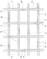
- the perspective view showing the appearance of the sunlight type plant factory in one embodiment of this application The top view of a part of roof of the solar-powered plant factory shown in FIG.
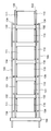
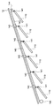
- the side view which shows notionally the mounting structure of the photovoltaic power generation panel in the solar-powered plant factory shown in FIG. The top view which shows notionally the mounting structure of the solar power generation panel in the solar-powered plant factory shown in FIG.
- the solar-powered plant factory (hereinafter, simply referred to as “plant factory”) in this embodiment has a building 1.
- the building 1 has an indoor space inside, and has a function of isolating the indoor space from the external environment.
- the building 1 itself may be the same as the structure of the conventional solar-powered plant factory, and is not limited to this, but in this embodiment, it is.
- the plants to be cultivated in the plant factory are cultivated.
- the method of cultivating the plant performed in the building 1 may be the same as the conventional one, but is not limited to this, but in this embodiment, the conventional method of cultivating the plant is followed.
- the method of cultivating the plant may be hydroponic culture, soil culture, or other solid medium culture.
- the building 1 includes a wall 11 and a roof 12.
- the wall 11 and the roof 12 are supported by columns and beams (not shown). Sunlight transmitted through the wall 11 or the roof 12 is incident on the indoor space inside the building 1.
- the wall 11 may also be transparent, but at least a part of the roof 12 is transparent so that sunlight can be guided into the interior space of the building 1 through the roof 12.
- the wall 11 is provided with an openable/closable door 11a for entering and leaving the indoor space of the building 1.
- the roof 12 is a gable type in this embodiment, the shape of the roof 12 is not limited to this, and for example, a well-known or well-known shape such as a hipped roof, a saw roof, a flat roof, and a one-sided roof is adopted. be able to.
- the roof 12 in this embodiment is configured as shown in the enlarged view of FIG.
- the roof 12 includes a frame material 13.
- the frame member 13 is made of metal.
- the frame member 13 is a rod-shaped member that is a plurality of rod-shaped members arranged in parallel with each other in a direction along the maximum inclination direction of the roof 12, and a horizontal direction that is orthogonal to the inclined rod-shaped member 13a.
- a horizontal rod-shaped member 13b which is a rod-shaped member arranged in parallel with each other.
- the intervals between the adjacent slant rod-shaped members 13 a are all the same in all parts of the roof 12.
- the intervals between the adjacent horizontal rod-shaped members 13b are all the same in all parts of the roof 12.
- the frame member 13 has a large number of rectangular windows 13c arranged vertically and horizontally in a grid pattern and surrounded by two adjacent inclined bar members 13a and two adjacent horizontal bar members 13b. Will be formed.
- the size and shape of each window 13c are not limited to this, but are the same in this embodiment.
- a window member 14 is fitted in each window portion 13c.
- the window member 14 is made of a translucent plate or film.
- the window member 14 may be publicly known or well known. In the case of a plate, the window member 14 can be made of, for example, glass, acrylic, or another resin.
- the window member 14 can be formed of, for example, vinyl chloride resin, polyethylene resin, or the like.
- the translucency that the window member 14 should have is, for example, 75% or more.
- the window member 14 in this embodiment has a size and a shape corresponding to each of the window portions 13c, and is fitted in each window portion 13c, and the window portion 13c is opened by, for example, a known method or a known appropriate method. It is fixed to the slanted rod-shaped member 13a and the horizontal rod-shaped member 13b that define it.
- the window member 14 does not need to be divided in units of the window portions 13c, and one window member 14 that is sized and shaped so as to straddle a plurality of adjacent window portions 13c may be a plurality of adjacent window portions 13c.
- the window portion 13c may be covered.
- a plurality of photovoltaic power generation panels 110 are provided in the indoor space of the building 1.
- the solar power generation panel 110 is provided with a light receiving surface 111 on its upper surface, and receives light from the light receiving surface 111 to generate power. Since the photovoltaic panel 110 is used in the indoor space of the building 1, it does not require high weather resistance.
- the photovoltaic panel 110 that does not have high weather resistance can have a simple configuration such as a PV cell (photovoltaic cell) attached to an acrylic plate or other plastic plate. The surface of the plastic plate to which the PV cell is attached becomes the light receiving surface 111.
- Such a solar power generation panel 110 can be manufactured at low cost and is lighter than a general solar power generation panel.
- all photovoltaic panels 110 are rectangular and plate-shaped. Of course, the four corners may be chamfered, or the plate may be a corrugated plate instead of a flat plate.
- all of the photovoltaic power generation panels 110 in this embodiment have light-receiving surfaces 111 having the same size and shape.
- all the photovoltaic power generation panels 110 in this embodiment have the same configuration.
- the size and shape of the light receiving surface 111 of each photovoltaic power generation panel 110 substantially correspond to the size and shape of the window portion 13c in the roof 12, and are configured to be slightly smaller than that.
- the plurality of photovoltaic panels 110 are arranged vertically and horizontally corresponding to the window members 14 on the roof 12, respectively. Each solar power generation panel 110 is arranged immediately below the window 13c. However, it is not required that the center of the light receiving surface 111 of the photovoltaic power generation panel 110 be directly below the center of the window 13c. Each of the photovoltaic power generation panels 110 is arranged under each of the window portions 13c because the shadow of the frame material 13 around the window portions 13c falls on the light receiving surface 111 of the photovoltaic power generation panel 110. This is to prevent the power generation efficiency from decreasing. The sun moves from east to west during the day, and its altitude varies depending on the season.
- the photovoltaic power generation panels 110 are arranged at positions where the reduction in the power generation efficiency of the photovoltaic power generation panel 110 due to the shadow formed by the frame material 13 can be most suppressed. At least the photovoltaic power generation panel 110 should be positioned as close to the lower surface of the roof 12 as possible within a range in which a change in angle as will be described later is allowed. It is advantageous to prevent shadows from falling.
- the photovoltaic power generation panel 100 in this embodiment can change their inclination in the north-south direction.
- the altitude of the sun changes depending on the season.
- the orientation of the light receiving surface 111 of the solar power generation panel 110 can be made to follow the seasonal elevation change of the sun, and the sunlight hitting the light receiving surface 111 can be changed. It is possible to keep the angle as close to vertical as possible. Thereby, the power generation efficiency in the photovoltaic power generation panel 110 can be improved.
- the angle change of the solar power generation panel in the north-south direction may be continuous or may be batch-type such as every 24 hours or once a week.
- At least a plurality of the multiple photovoltaic panels 110 in this embodiment are configured such that their inclinations are collectively changed by driving one power unit. ing. More specifically, among the photovoltaic panels 110 in this embodiment, one row of photovoltaic panels in the direction of inclination of the roof 12 has its inclination changed collectively by driving one power unit. It is supposed to be done. However, the range of the photovoltaic panels 110 whose tilts are collectively changed by one power unit does not have to be one row of photovoltaic panels 110 in the tilt direction of the roof 12.
- one row of solar power generation panels 110 arranged in the horizontal direction may be configured so that their inclinations can be collectively changed by one power unit, and 9 solar power generations of 3 ⁇ 3.
- the tilts of the panels 110 may be collectively changed by one power unit, and all the solar panels 110 may be collectively tilted by one power unit. It doesn't matter if it is like this.
- FIGS. 3 An example of a mechanism for changing the angle of the photovoltaic panel 110 is schematically shown in FIGS. 3 is a side view and FIG. 4 is a plan view.
- the photovoltaic panel 110 is directly below the roof 12.
- FIG. 3 in this example, six solar power generation panels 110 are arranged in the inclination direction of the roof 12.
- the inclination angle of a set of six photovoltaic panels 110 arranged in the inclination direction of the roof 12 is collectively changed by one drive device described later.
- the mechanism shown in FIGS. 3 and 4 can also be adopted in other solar power generation panels 110 arranged in the inclination direction of the roof 12, and this is not always the case, but this is the case in this embodiment.
- Each of the photovoltaic power generation panels 110 faces south, and the light receiving surface 111 thereof faces upward. Although not limited to this, the upper and lower sides of each rectangular photovoltaic power generation panel 110 are horizontal.
- Each solar power generation panel 110 has an upper rod body 131, which is a rod-shaped body extending along the slope of the roof 12 on both outer sides of the upper side of the solar power generation panel 110, on each side surface immediately below the upper side thereof. Is supported. More specifically, the upper rod 131 and the solar power generation panel 110 are connected by a cylindrical upper shaft 132 that is rotatable with respect to each of the upper rod 131 and the solar power generation panel 110. ing.
- the upper shaft 132 serves as an axis, and the angle between the upper rod 131 and the photovoltaic power generation panel 110 when viewed from the side is changeable.
- Each solar power generation panel 110 is a lower rod body that is a rod-shaped body that extends along the slope of the roof 12 on both sides of the lower side of the solar power generation panel 110 on both outer sides of the lower side of the solar power generation panel 110. It is supported by 133. More specifically, the lower rod body 133 and the photovoltaic power generation panel 110 are connected by a lower shaft 134 having a cylindrical shape that is rotatable with respect to each of the lower rod body 133 and the photovoltaic power generation panel 110. ing.
- the lower shaft 134 serves as an axis, and the angle between the lower rod 133 and the photovoltaic panel 110 when viewed from the side is changeable.
- the upper rod body 131 and the lower rod body 133 are connected to the drive device 135.
- the drive device 135 can move at least one of the upper rod body 131 and the lower rod body 133 in the length direction thereof in accordance with an appropriate driving force such as hydraulic pressure.
- the position of the lower rod body 133 is moved to the right in FIGS.
- the distance between the lower rod body 133 and the upper rod body 131 is expanded, and the lower rod body 133 is supported by the upper rod body 131 and the lower rod body 133.
- the photovoltaic panels 110 all stand up by the same angle.
- the position of the lower rod body 133 is moved to the left in FIGS. 3 and 4, for example, the distance between the lower rod body 133 and the upper rod body 131 is narrowed, and the upper rod body 131 and the lower rod body 133 are separated.
- the supported photovoltaic panels 110 all sleep at the same angle. In this way, the tilt angles of a plurality of, in this example, six photovoltaic panels 110 can be collectively changed in the same manner by driving only one drive device 135.
- the drive device 135 does not need to be fixed to the drive device 135 and may be directly or indirectly through another member. It can be fixed to the building 1. Further, the driving device 135 does not have to be arranged inside the building 1, and may be provided outside the building 1.
- the change of the angle of the photovoltaic power generation panel 110 can be achieved not only by the mechanism shown in FIGS. 3 and 4 but also by the mechanism shown in the side view of FIG.
- the side view of FIG. 5 is for changing the height in the vicinity of the corresponding apex (for example, the apex at the upper right of each solar panel 110 shown in FIG. 2) of the solar panel 110. It is a conceptual representation of the mechanism.
- An upper right pulley 141 which is a pulley, is provided near the upper right of FIG. 3 of each photovoltaic panel 110.
- two upper right pulleys 142 which are two pulleys, are provided.
- a wire or other linear member 143 is wound around the upper right pulley 141 and the upper right auxiliary pulley 142.
- the distal end of the linear body 143 is fixed to a fixed body 144 which is a predetermined object for fixing the distal end of the linear body 143, and the proximal end of the linear body 143 is wound around a drum 145.
- the drum 145 is rotatable by a driving device (not shown), and is capable of winding or unwinding the filament body 143. When the drum 145 winds the filament body 143, the length of the filament body 143 from the drum 145 to the fixed body 144 becomes shorter, and the position of each upper right auxiliary pulley 142 remains unchanged.
- the upper right pulley is pulled up, and the upper right portion of the photovoltaic panel 110 is pulled up.
- the drum 145 unwinds the filament body 143
- the length of the filament body 143 from the drum 145 to the fixed body 144 becomes long, and the position of each upper right auxiliary pulley 142 remains unchanged.
- the upper right pulley of the panel 110 is lowered, and the upper right portion of the photovoltaic power generation panel 110 is lowered.
- the upper right portion of the photovoltaic power generation panel 110 can be collectively changed in the vertical position by driving the driving device (not shown).
- all the upper right portions of the photovoltaic panels 110 under the roof 12 are collectively driven by one drive device. It can also be moved up and down.
- the configuration shown in FIG. 5 is, for example, not only in the upper right corner of the photovoltaic power generation panel 110 shown in FIG. Alternatively, it can be adopted at four locations near the four vertices of the photovoltaic panel 110. As a result, the upper and lower positions of the solar power generation panel 110, or the four corners of the solar power generation panel 110 can be collectively changed in the vertical direction by driving a driving device (not shown). become able to.
- the former the two vertices that do not move up and down may be simply hung by a linear body
- it is possible to change the inclinations of the plurality of photovoltaic panels 110 in the north-south direction. If the latter is adopted, it becomes possible to freely change the inclination in the north-south direction and the inclination in the east-west direction of the plurality of photovoltaic power generation panels 110.
- the latter it is also possible to change the direction of the light receiving surface of the photovoltaic power generation panel in accordance with the movement of the sun during the day.
- the method of using the plant factory as described above is the same as the method of using the conventional plant factory.
- the photovoltaic power generation panel 110 generates power.
- a solar-powered plant factory for example, electric power is required for nighttime lighting, air conditioning for indoor air conditioning, humidity adjustment, and the like.
- the power generated by the photovoltaic power generation panel 110 generating power can be used as power required for lighting, air conditioning, and the like.
- the electric power generated by the solar power generation panel 110 may be a target for power sale. This makes it possible to indirectly reduce the running cost of the plant factory. Further, by arranging the photovoltaic power generation panel 110 under the roof 12 of the building 1, the following secondary effects are also produced.
- the photovoltaic panel 110 below the roof 12 and above the plant to be cultivated allows the plant to be placed in the shadow produced by the photovoltaic panel 110.
- the interior of the building 1 can be cooled compared to when the photovoltaic panel 110 is not present.
- the solar power generation panel 110 is provided inside the building 1, particularly immediately below the roof 12, so that such a device does not need to be devised.
- the solar panels 110 are connected in parallel.
- the large number of photovoltaic power generation panels 110 are arranged in series.
- a large number of solar panels 110 are connected in series and dirt is attached to the light receiving surface 111 of one of the solar panels 110 due to dead leaves or twigs (most sunlight In the case of the present invention in which the power generation panel 110 is in the indoor space of the building 1, such a situation is difficult to imagine), or dead leaves and twigs are placed on the window member 14 on the solar power generation panel 110 to stain the window member 14.
- the power generation capacity of the solar power generation panel 110 becomes lower than the power generation capacity of other solar power generation panels 110.
- the photovoltaic power generation panel 110 When such a decrease in power generation occurs in one of the photovoltaic power generation panels 110 in a power generation facility in which a large number of photovoltaic power generation panels 110 are connected in series, the photovoltaic power generation panel 110 is connected to the other photovoltaic power generation panels 110 in series.
- the solar power generation panel 110 of the present invention functions as a resistance, so to speak, and tends to greatly affect the power generation capacity of the entire power generation facility.
- the photovoltaic panel 110 is It does not function as a resistance to the photovoltaic power generation panel 110, and its effect is that the amount of current output from the power generation equipment including a large number of photovoltaic power generation panels 110 is from the photovoltaic power generation panel 110 in which the amount of current has decreased. Since it is only reduced by the amount of decrease in the amount of current, the above-mentioned great influence does not occur.
- the photovoltaic panel 110 can be hung using the filament 143.
- each photovoltaic power generation panel 110 can be tilted arbitrarily in the north-south direction or the east-west direction.
- the plurality of solar power generation panels 110 can change their inclinations in the east-west direction, the plurality of solar power generation panels 110 are In the morning and evening hours, by setting the light receiving surface 111 of the photovoltaic power generation panel 110 in either the east or west direction to be vertical or substantially vertical, the light receiving surface 111 of the photovoltaic power generation panel 110 may face the sun.
- the light-receiving surface 111 of the photovoltaic power generation panel 110 does not need to face exactly east or west exactly, and the light-receiving surface 111 is within 30 degrees (preferably within 15 degrees) in the horizontal direction from the direction of the sun. ) It is sufficient if it faces in the direction of.
- the angle formed by the straight line along the maximum inclination direction of the light receiving surface 111 of the photovoltaic power generation panel 110 and the vertical straight line is within 15 degrees (preferably within 10 degrees). That's enough.
- “Morning and evening” means a time zone of up to 15 degrees if the sun altitude (elevation angle) has a margin (up to 10 degrees if there is no margin). Such a configuration is useful for maintaining the power generation efficiency of each photovoltaic panel 110 even in the morning and evening hours. If such a configuration is adopted, the photovoltaic power generation panels 110 may be located at overlapping positions when viewed from the sun, but in order to maintain the power generation efficiency of the photovoltaic power generation panel 110 on the rear side to some extent. It is preferable that each solar power generation panel 110 be of a type that transmits sunlight.
Abstract
The present invention provides technology for limiting the costs of a plant factory having photovoltaic panels. A sunlight-type plant factory is provided with a building. The roof 12 of the building is transparent, and sunlight can enter into the inner space of the building. Photovoltaic panels 110 are disposed in the inner space of the building. The inclination angle of the photovoltaic panels 110 can be changed in the north-south direction.
Description
本発明は、植物工場(本願における「植物工場」にはビニルハウスと称されるような簡易なものを含む)に関し、特には、太陽光発電パネルを備えており、発電を行う能力を有する太陽光利用型植物工場に関する。
The present invention relates to a plant factory (including a simple one such as a vinyl house in the “plant factory” in the present application), and in particular, a solar power generation panel equipped with a solar power generation capability. Light-related plant factory.
近年、植物工場に対する投資が盛んになっている。植物工場は、内部環境をコントロールした閉鎖的または半閉鎖的な空間で植物を計画的に生産するシステムであり、安全な食料の安定した周年供給を実現しうる技術である。そのような観点から、植物工場の果たす役割は今後益々大きくなっていくことが予想される。
ただし、本願では、閉鎖的な空間で植物を計画的に生産する植物工場であって、その内部を外部環境から隔離する壁及び屋根を有しており、少なくとも屋根の少なくとも一部が太陽光を透過する素材でできている建屋を備える、太陽光利用型植物工場のみを植物工場の対象とする。 In recent years, investment in plant factories has increased. A plant factory is a system that systematically produces plants in a closed or semi-closed space with controlled internal environment, and is a technology that can realize a stable year-round supply of safe food. From such a viewpoint, it is expected that the role of plant factories will continue to grow.
However, in the present application, it is a plant factory that systematically produces plants in a closed space, and has a wall and a roof that isolate the inside from the external environment, and at least a part of the roof receives sunlight. Only plant plants using sunlight, which have buildings made of transparent materials, will be targeted for plant factories.
とはいえ、植物工場、或いはそれを経営する法人の中で黒字化しているものは少なく、その運用、経営が経済的に安定しているとはいい難い。その問題の多くは、植物工場のコストの大きさに起因する。植物工場は、一般的な農場と比較してイニシャルコスト及びランニングコストの双方が大きく、特にそのランニングコストの大きさが頻繁に問題となる。
そしてランニングコストの中である程度大きな比率を占めるのが光熱費であり、特には電気代である。 However, there are few plant factories or corporations that manage them, and it is hard to say that their operation and management are economically stable. Many of the problems stem from the high cost of plant factories. A plant factory has a large initial cost and a high running cost as compared with a general farm, and in particular, the running cost is often a problem.
The utility cost accounts for a relatively large proportion of the running cost, and the electricity cost is particularly high.
そのような観点から、植物工場に、例えば太陽光発電パネルを設けることにより、電力の調達を自前で行おうとする動きもある。それによれば植物工場の運用に不可欠な電気代を抑制することが可能となり、場合によっては売電すら可能となるため、コスト抑制だけでなく利益の向上を達成できる可能性すらある。
From such a point of view, there is a movement to procure electric power by installing a solar power generation panel in a plant factory, for example. According to this, it is possible to suppress the electricity bill that is indispensable for the operation of the plant factory, and even to sell the electric power in some cases, so that not only cost reduction but also profit improvement may be achieved.
植物工場に太陽光発電パネルを設ける場合、今の所の試みでは、太陽光発電パネルを、建屋の屋根に取付けることが多く、その場合には屋根の上にそれを取付けるようにしている。これは従来の太陽光発電パネルは、それが屋根(植物工場の屋根とは限られない。)に取付けられる場合には、屋根の上に取付ける(或いは太陽光発電パネルそのもので屋根を構成する)ように設計されており、取付に用いられる金具等もそれを意図して設計されているからである。
また、屋根自体を太陽光発電パネルにより構成する場合もある。 When installing photovoltaic panels in plant factories, current attempts are often to attach the photovoltaic panels to the roof of a building, in which case they are mounted on the roof. This is a conventional photovoltaic panel, if it is mounted on the roof (not necessarily the roof of a plant factory), it is mounted on the roof (or the photovoltaic panel itself constitutes the roof). This is because the metal fittings used for mounting are also designed with that in mind.
Further, the roof itself may be composed of a photovoltaic power generation panel.
ところで、屋根の上側に、つまり、外部の環境に晒される状態で太陽光発電パネルを用いるのであれば、太陽光発電パネルには例えば高い耐候性が要求されることになる。また、高い耐候性が必要な太陽光発電パネルはその頑丈さ故に重量が大きくなりがちであり、それを支持する架台も頑丈で重量の大きなものになりがちである。これら事情は太陽光発電パネルの製造コストの高騰に影響し、また、建屋の建築コストの高騰にも影響するので、植物工場のイニシャルコストの高騰に繋がる。屋根自体を構成する太陽光発電パネルでも外部の環境に晒される点では上記と同様であり、このような太陽光発電パネルは他の用途に使用できないものとなりがちであるから、その製造コストはやはり高くなる。
また、耐候性に優れた太陽光発電パネルを用いるにせよ、外部の環境に晒される状態で太陽光発電パネルを使用するとそのメンテナンスに必要なランニングコストも嵩む。外部の環境に晒された状態で使用される太陽光発電パネルには経年劣化がつきものであり、また、仮に経年劣化がなかったとしても、例えば、土や枯れ葉が太陽光発電パネルの表面に付着して太陽光発電パネルの表面が汚れるだけで太陽光発電パネルの発電効率が下がるため、その清掃等のためにランニングコストが生じることになる。 By the way, if the solar power generation panel is used on the upper side of the roof, that is, in a state of being exposed to the external environment, the solar power generation panel is required to have high weather resistance, for example. In addition, a solar power generation panel that requires high weather resistance tends to be heavy due to its toughness, and a pedestal that supports the solar power generation panel tends to be tough and heavy. These circumstances affect the increase in the manufacturing cost of the photovoltaic power generation panel and also the increase in the building cost of the building, which leads to the increase in the initial cost of the plant factory. The photovoltaic panels that make up the roof itself are similar to the above in that they are exposed to the external environment, and such photovoltaic panels tend to be unusable for other purposes, so their manufacturing costs are also Get higher
Further, even if a solar power generation panel having excellent weather resistance is used, if the solar power generation panel is used in a state where it is exposed to the external environment, the running cost required for its maintenance increases. Photovoltaic panels used in the condition of being exposed to the external environment are subject to deterioration over time, and even if there is no deterioration over time, for example, soil or dead leaves will adhere to the surface of the photovoltaic panel. Since the surface of the photovoltaic power generation panel is only soiled, the photovoltaic power generation efficiency of the photovoltaic power generation panel is lowered, so that running costs are required for cleaning the photovoltaic power generation panel.
本願発明は、太陽光発電パネルを有する植物工場のコストを抑制する技術を提供することをその課題とする。
The subject of the present invention is to provide a technique for suppressing the cost of a plant factory having a photovoltaic power generation panel.
上述の課題を解決するため、本願発明者は研究を重ねた。その結果本願発明者は、太陽光発電パネルに高い耐候性が必要となるのは太陽光発電パネルが建屋の屋根の上にあるからであって、太陽光発電パネルを外部の環境に晒されない建屋の屋内に設ければ、太陽光発電パネルに高い耐候性が必要なくなり、また、発電効率の低下の原因となる表面の汚れも少なくなる、という知見を得た。
本願発明はそのような知見に基づく。 In order to solve the above-mentioned subject, the inventor of the present application has conducted repeated research. As a result, the inventor of the present application needs high weather resistance for the photovoltaic panel because the photovoltaic panel is on the roof of the building, and the photovoltaic panel is not exposed to the external environment. It has been found that the solar power generation panel does not need to have high weather resistance when installed indoors, and the surface contamination that causes a decrease in power generation efficiency is reduced.
The present invention is based on such knowledge.
本願発明者が提案するのは以下の発明である。
本願発明は、その内部を外部環境から隔離する壁及び屋根を有しており、少なくとも前記屋根が太陽光を透過する素材でできている建屋と、前記建屋の内部の前記屋根付近に設けられた、複数の太陽光発電パネルと、を備えている太陽光利用型植物工場である。
本願発明における太陽光利用型植物工場の一部となる建屋は、従来からの太陽光利用型植物工場と基本的に同じものでもよく、従来からの太陽光利用型植物工場と完全に同じものでも良い。
本願発明における太陽光利用型植物工場は、複数の太陽光発電パネルを備えている。太陽光発電パネルは、一般的な太陽光発電パネルと同様に太陽光を受けることにより発電を行うものとなっている。そして、本願発明における太陽光発電パネルは、建屋の中に設けられる。したがって、本願発明における太陽光利用型植物工場は、その一部を構成する太陽光発電パネルに高い耐候性が必要なくなるため、その製造原価を下げることができるから、太陽光利用型植物工場の全体として見た場合にもそのイニシャルコストを下げることが可能となるし、建屋の外に太陽光発電パネルを設ける場合と比較して太陽光発電パネルの経年劣化も少なく、またその表面に汚れが生じる原因の多くを排除できるからそのランニングコストも小さくなる。例えば、高い耐候性を有さない太陽光発電パネルは、ポリカーボネート板やアクリル板その他のプラスチック板にPVセル(photovoltaic cell)を貼り付けたような簡易な構成とすることができる。このような太陽光発電パネルは低コストでの製造が可能であり、また軽量である。 The inventor of the present application proposes the following invention.
The present invention has a wall and a roof that isolate the interior from the external environment, and at least the roof is made of a material that transmits sunlight, and the interior of the building is provided near the roof. , A solar-powered plant factory that includes a plurality of photovoltaic panels.
The building that is a part of the solar-powered plant factory in the present invention may be basically the same as a conventional solar-powered plant factory, or may be completely the same as a conventional solar-powered plant factory. good.
The solar-powered plant factory according to the present invention includes a plurality of solar power generation panels. The solar power generation panel generates power by receiving sunlight like a general solar power generation panel. Then, the photovoltaic panel according to the present invention is provided in the building. Therefore, since the solar-powered plant factory in the present invention does not require high weather resistance for the photovoltaic panels that form a part of the solar-powered plant factory, it is possible to reduce the manufacturing cost thereof. It is possible to reduce the initial cost even if it is viewed as, and the deterioration of the solar power generation panel over time is less compared to the case where the solar power generation panel is installed outside the building, and the surface is contaminated. Since many of the causes can be eliminated, the running cost is also reduced. For example, a photovoltaic panel that does not have high weather resistance can have a simple structure in which a PV cell (photovoltaic cell) is attached to a polycarbonate plate, an acrylic plate, or another plastic plate. Such a photovoltaic panel can be manufactured at low cost and is lightweight.
本願発明における太陽光利用型植物工場における複数の前記太陽光発電パネルのそれぞれは、少なくとも南北方向でその傾きを変更できるようになっていてもよい。
太陽の高度は、季節によって変化する。太陽光発電パネルの傾きを南北方向で変化させることにより、公知或いは周知のように通常太陽光発電パネルの上面に位置している受光面の向きを太陽の季節的な高度変化に追随させることが可能となり、受光面に当たる太陽光の角度を可能な限り垂直に近い角度に保つことが可能となる。それにより、太陽光発電パネルにおける発電効率を向上させられるようになる。かかる南北方向での太陽光発電パネルの角度変化は、連続的なものでも良いし、例えば、24時間おき、一週間おき等のバッチ的なものでも良い。
他方、太陽光発電パネルは、東西方向でその傾きを変更できるようになっていてもよい。太陽は一日の中で東から西へと移動する。太陽光発電パネルが、東西方向でその傾きを変更できるようになっていれば、その一日の中での太陽の移動に追随させて太陽光発電パネルの受光面の向きを変化させることで、太陽光発電パネルの受光面に当たる太陽光の角度を可能な限り垂直に近い角度に保つことが可能となる。それにより、太陽光発電パネルにおける発電効率を向上させられるようになる。かかる東西方向での太陽光発電パネルの角度変化は、連続的なものでも良いし、例えば、1分おき、15分おき等のバッチ的なものでも良い。
太陽光発電パネルが、南北方向でも東西方向でもその傾きを変化させる場合、南北方向の傾きの変化と東西方向の傾きの変化は、連動して行われても良いし、個別に行われても良い。
複数の太陽光発電パネルが東西方向でもその傾きを変化させられるようになっている場合、複数の前記太陽光発電パネルは、朝夕の時間帯では、東西いずれかの方向に前記太陽光発電パネルの受光面を向けた状態で鉛直乃至略鉛直となることで、前記太陽光発電パネルの前記受光面を太陽に対向させるようになっていてもよい。なお、本願において「東西いずれかの方向に前記太陽光発電パネルの受光面を向けた状態」とは、太陽光発電パネルの受光面が真東、真西を向いた状態を必ずしも意味せず、受光面が太陽の方向から水平方向で30度位内(好ましくは15度以内)の方向を向いていればその条件が充足されるものとする。本願において、ほぼ鉛直とは、太陽光発電パネルの最大傾斜方向に沿う線と、鉛直な線とがなす角が15度以内(好ましくは10度以内)であることを意味することとする。本願において「朝夕」とは太陽高度(仰角)が余裕を見て15度以内(余裕を見ないなら10度以内)の時間帯を意味するものとする。朝夕の時間帯においては、太陽光発電パネルの発電効率がどうしても悪化しがちである。そのような時間帯において、太陽光発電パネルを鉛直かほぼ鉛直に保てば太陽光発電パネルによる発電効率を向上させることが可能である。このようにした場合、太陽光発電パネルは、太陽に対して前後に並ぶこともあり得る。そうすると太陽に近い側の太陽光発電パネルでは十分な発電効率を得られるけれども、手前の太陽光発電パネルの後ろに隠れた太陽から遠い側の太陽光発電パネルでは十分な発電効率が得られないこともあり得る。そのようなことがないように、かかる目的で使用される場合における太陽光発電パネルは太陽光を透過するタイプのものとするのが好ましい。 Each of the plurality of solar power generation panels in the solar-powered plant factory according to the present invention may be capable of changing its inclination at least in the north-south direction.
The altitude of the sun changes depending on the season. By changing the inclination of the solar power generation panel in the north-south direction, as is well known or well known, the direction of the light receiving surface, which is usually located on the upper surface of the solar power generation panel, can be made to follow the seasonal elevation change of the sun. This makes it possible to keep the angle of the sunlight hitting the light receiving surface as close to vertical as possible. Thereby, the power generation efficiency of the photovoltaic power generation panel can be improved. The change in the angle of the solar power generation panel in the north-south direction may be continuous or may be batch-like, such as every 24 hours or once a week.
On the other hand, the solar panel may be capable of changing its inclination in the east-west direction. The sun moves from east to west during the day. If the solar panel can change its tilt in the east-west direction, by changing the direction of the light-receiving surface of the solar panel by following the movement of the sun during the day, It is possible to keep the angle of the sunlight hitting the light receiving surface of the photovoltaic power generation panel as close to the vertical as possible. Thereby, the power generation efficiency of the photovoltaic power generation panel can be improved. The change in the angle of the solar power generation panel in the east-west direction may be continuous or may be batch-like such as every 1 minute or every 15 minutes.
When the solar panel changes its inclination in the north-south direction or the east-west direction, the change in the north-south direction and the change in the east-west direction may be performed in conjunction with each other or individually. good.
When the plurality of solar power panels can change its inclination even in the east-west direction, the plurality of the solar power panels, in the morning and evening hours, in the east or west direction of the solar power panel The light receiving surface of the solar power generation panel may face the sun by being vertical or substantially vertical with the light receiving surface facing. In the present application, "a state in which the light receiving surface of the solar power generation panel is oriented in either east or west" does not necessarily mean that the light receiving surface of the solar power generation panel is facing east or true west, It is assumed that the condition is satisfied if the light receiving surface is oriented within 30 degrees (preferably within 15 degrees) in the horizontal direction from the direction of the sun. In the present application, "substantially vertical" means that the angle formed by a line along the maximum inclination direction of the photovoltaic panel and the vertical line is within 15 degrees (preferably within 10 degrees). In the present application, "morning and evening" means a time zone in which the sun altitude (elevation angle) is within 15 degrees with a margin (or within 10 degrees without a margin). In the morning and evening hours, the power generation efficiency of photovoltaic panels tends to deteriorate. In such a time zone, it is possible to improve the power generation efficiency of the photovoltaic power generation panel by keeping the photovoltaic power generation panel vertical or almost vertical. In this case, the photovoltaic panels may be lined up in front of and behind the sun. That way, the solar panels near the sun can get enough power generation efficiency, but the solar panels farther from the sun hidden behind the solar panels in the front can't get enough power generation efficiency. There is also a possibility. In order to prevent such a situation, it is preferable that the solar power generation panel used for such a purpose is of a type that transmits sunlight.
複数の前記太陽光発電パネルの少なくとも複数は、1つの動力装置を駆動させることで、一括してその傾きが変更されるようになっていても構わない。
太陽光発電パネルの複数の傾きを1つの動力装置によって一括して変更可能とすれば、動力装置の数を減らすことによるコストダウンも見込める。 At least a plurality of the plurality of photovoltaic power generation panels may be configured such that their inclinations can be collectively changed by driving one power unit.
If a plurality of tilts of the photovoltaic power generation panel can be collectively changed by one power unit, cost reduction can be expected by reducing the number of power units.
太陽光利用型植物工場における建屋の屋根は上述したように、太陽光を透過する素材でできている。その限りにおいて建屋及び屋根の構成には特に制限はない。
例えば、前記屋根は、縦横にそれぞれ複数列配置された棒状材によって構成された枠材と、前記枠材において碁盤の目状に存在する前記棒状材にその四方を囲まれた矩形の範囲である窓部それぞれに設けられた、太陽光を透過する素材でできている膜材又は板材である窓部材とを備えていてもよい。その場合、複数の前記太陽光発電パネルはそれぞれ、前記窓部の大きさよりも小さくされており、前記窓部の直下にそれぞれ配されていてもよい。
太陽光発電パネルの受光面は常識通り基本的に上向きとされるが、これにより、受光面に枠材の影が落ちることを抑制することが可能となる。
この場合、複数の前記太陽光発電パネルはそれぞれ矩形とすることができる。矩形の太陽光発電パネルのそれぞれは、窓部よりも一回り小さくするのが実際的である。 As described above, the roof of the building in the solar-powered plant factory is made of a material that transmits sunlight. To that extent, there are no particular restrictions on the structure of the building and roof.
For example, the roof is a frame member formed of rod-shaped members arranged vertically and horizontally in a plurality of rows, and a rectangular range surrounded by the rod-shaped members existing in a grid pattern on the frame member on all sides. A window member, which is a film material or a plate material made of a material that transmits sunlight, may be provided in each of the windows. In that case, each of the plurality of photovoltaic power generation panels may be smaller than the size of the window portion, and may be arranged directly below the window portion.
The light receiving surface of the photovoltaic power generation panel is basically directed upward, as is common sense, but this makes it possible to prevent the shadow of the frame member from falling on the light receiving surface.
In this case, each of the plurality of photovoltaic panels can be rectangular. It is practical for each rectangular photovoltaic panel to be one size smaller than the window.
本願発明者は、太陽光利用型植物工場における太陽光発電パネルの配置構造をも、本願発明の一態様として提案する。かかる太陽光発電パネルの配置構造の効果は、本願発明における太陽光利用型植物工場の効果と同じである。
一例となる太陽光利用型植物工場における太陽光発電パネルの配置構造は、その内部を外部環境から隔離する壁及び屋根を有しており、少なくとも前記屋根が太陽光を透過する素材でできている建屋を備えている太陽光利用型植物工場における太陽光発電パネルの配置構造であって、前記建屋の内部の前記屋根付近に設けられた、複数の太陽光発電パネルを含む、太陽光発電パネルの配置構造である。 The inventor of the present application also proposes an arrangement structure of solar power generation panels in a solar-powered plant factory as one aspect of the present invention. The effect of the arrangement structure of the solar power generation panel is the same as the effect of the solar-powered plant factory in the present invention.
The arrangement structure of a photovoltaic panel in a solar-powered plant factory as an example has a wall and a roof that isolate the interior from the external environment, and at least the roof is made of a material that transmits sunlight. A layout structure of a photovoltaic panel in a solar-powered plant factory having a building, provided near the roof inside the building, including a plurality of photovoltaic panels, It is an arrangement structure.
以下、図面を参照しつつ、本発明の好ましい一実施形態を説明する。
A preferred embodiment of the present invention will be described below with reference to the drawings.
この実施形態における太陽光利用型植物工場(以下、単に「植物工場」と称する。)は、建屋1を有している。
建屋1は、その内部に室内空間を有しており、室内空間を外部環境から隔離する機能を有している。建屋1自体は、従来の太陽光利用型植物工場の構成をそのまま踏襲したもので良く、これには限られないがこの実施形態では、そうされている。建屋1内部の室内空間では、植物工場での栽培の対象となる植物が栽培される。建屋1の中で行われる植物の栽培の方法自体は、従来のままで良く、これには限られないがこの実施形態では、従来の植物の栽培方法を踏襲することとしている。例えば、植物の栽培方法は、水耕栽培でも良く、土壌栽培、その他の固形培地栽培でも良い。建屋1の内部には、栽培方法に応じて植物の栽培のために必要となる設備が存在するが、後述する太陽光発電パネル及びそれに関連する設備を除けば、植物の栽培のために必要となるそれら設備は従来のそれらと同様で構わない。これには限られないが、この実施形態におけるそれら設備は、従来のものを踏襲している。
建屋1は、壁11と、屋根12を備えている。壁11と屋根12とは、図示を省略の柱や梁によって支持されている。建屋1の内部の室内空間には壁11又は屋根12を透過した太陽光が入射するようになっている。壁11も透明であって良いが、少なくとも屋根12の一部は透明であり、屋根12を介して建屋1の室内空間の中に太陽光を導くことができるようになっている。壁11には、建屋1の室内空間に出入りするための開閉自在な扉11aが設けられている。
なお、屋根12はこの実施形態では切妻型であるが、屋根12の形状はこれには限られず、例えば、寄棟屋根、鋸屋根、陸屋根、片流れ屋根等の公知、或いは周知の形状を採用することができる。 The solar-powered plant factory (hereinafter, simply referred to as “plant factory”) in this embodiment has a building 1.
The building 1 has an indoor space inside, and has a function of isolating the indoor space from the external environment. The building 1 itself may be the same as the structure of the conventional solar-powered plant factory, and is not limited to this, but in this embodiment, it is. In the indoor space inside the building 1, the plants to be cultivated in the plant factory are cultivated. The method of cultivating the plant performed in the building 1 may be the same as the conventional one, but is not limited to this, but in this embodiment, the conventional method of cultivating the plant is followed. For example, the method of cultivating the plant may be hydroponic culture, soil culture, or other solid medium culture. Inside the building 1, there are facilities necessary for cultivating plants depending on the cultivation method, but except for the photovoltaic power generation panel and the facilities related thereto, which will be described later, it is necessary for cultivating plants. Those equipments that are the same as those of the conventional equipment may be used. Although not limited to this, the facilities in this embodiment follow the conventional ones.
The building 1 includes awall 11 and a roof 12. The wall 11 and the roof 12 are supported by columns and beams (not shown). Sunlight transmitted through the wall 11 or the roof 12 is incident on the indoor space inside the building 1. The wall 11 may also be transparent, but at least a part of the roof 12 is transparent so that sunlight can be guided into the interior space of the building 1 through the roof 12. The wall 11 is provided with an openable/closable door 11a for entering and leaving the indoor space of the building 1.
Although theroof 12 is a gable type in this embodiment, the shape of the roof 12 is not limited to this, and for example, a well-known or well-known shape such as a hipped roof, a saw roof, a flat roof, and a one-sided roof is adopted. be able to.
建屋1は、その内部に室内空間を有しており、室内空間を外部環境から隔離する機能を有している。建屋1自体は、従来の太陽光利用型植物工場の構成をそのまま踏襲したもので良く、これには限られないがこの実施形態では、そうされている。建屋1内部の室内空間では、植物工場での栽培の対象となる植物が栽培される。建屋1の中で行われる植物の栽培の方法自体は、従来のままで良く、これには限られないがこの実施形態では、従来の植物の栽培方法を踏襲することとしている。例えば、植物の栽培方法は、水耕栽培でも良く、土壌栽培、その他の固形培地栽培でも良い。建屋1の内部には、栽培方法に応じて植物の栽培のために必要となる設備が存在するが、後述する太陽光発電パネル及びそれに関連する設備を除けば、植物の栽培のために必要となるそれら設備は従来のそれらと同様で構わない。これには限られないが、この実施形態におけるそれら設備は、従来のものを踏襲している。
建屋1は、壁11と、屋根12を備えている。壁11と屋根12とは、図示を省略の柱や梁によって支持されている。建屋1の内部の室内空間には壁11又は屋根12を透過した太陽光が入射するようになっている。壁11も透明であって良いが、少なくとも屋根12の一部は透明であり、屋根12を介して建屋1の室内空間の中に太陽光を導くことができるようになっている。壁11には、建屋1の室内空間に出入りするための開閉自在な扉11aが設けられている。
なお、屋根12はこの実施形態では切妻型であるが、屋根12の形状はこれには限られず、例えば、寄棟屋根、鋸屋根、陸屋根、片流れ屋根等の公知、或いは周知の形状を採用することができる。 The solar-powered plant factory (hereinafter, simply referred to as “plant factory”) in this embodiment has a building 1.
The building 1 has an indoor space inside, and has a function of isolating the indoor space from the external environment. The building 1 itself may be the same as the structure of the conventional solar-powered plant factory, and is not limited to this, but in this embodiment, it is. In the indoor space inside the building 1, the plants to be cultivated in the plant factory are cultivated. The method of cultivating the plant performed in the building 1 may be the same as the conventional one, but is not limited to this, but in this embodiment, the conventional method of cultivating the plant is followed. For example, the method of cultivating the plant may be hydroponic culture, soil culture, or other solid medium culture. Inside the building 1, there are facilities necessary for cultivating plants depending on the cultivation method, but except for the photovoltaic power generation panel and the facilities related thereto, which will be described later, it is necessary for cultivating plants. Those equipments that are the same as those of the conventional equipment may be used. Although not limited to this, the facilities in this embodiment follow the conventional ones.
The building 1 includes a
Although the
この実施形態では、屋根12の大半が透明である。この実施形態における屋根12は、図2の拡大図に示したように構成されている。
屋根12は、枠材13を備えている。枠材13は、金属製である。枠材13は、屋根12の最大傾斜方向に沿う方向に、互いに平行となるようにして複数本配された棒状材である傾斜棒状材13aと、傾斜棒状材13aと直交するように水平方向に、互いに平行となるようにして複数本配された棒状材である水平棒状材13bとを含んで構成されている。
これには限られないが、この実施形態では、隣り合う傾斜棒状材13a間の間隔は、屋根12のすべての部分ですべて同一となるようにされている。また、これには限られないが、この実施形態では、隣り合う水平棒状材13b間の間隔は、屋根12のすべての部分ですべて同一となるようにされている。枠材13には、隣接する2本の傾斜棒状材13aと、隣接する2本の水平棒状材13bとにより囲まれた、碁盤の目状に縦横に配された矩形の多数の窓部13cが形成されることになる。各窓部13cの大きさ、形状は、この限りでないが、この実施形態ではすべて同じである。
各窓部13cには、窓部材14が嵌められている。窓部材14は、透光性を有する板又は膜により構成されている。窓部材14は、公知或いは周知のもので良い。板である場合、窓部材14は、例えば、ガラスや、アクリルその他の樹脂により構成することができる。膜である場合、窓部材14は、例えば、塩化ビニル樹脂、ポリエチレン樹脂等によって形成することができる。窓部材14が有すべき透光性は、例えば、75%或いはそれ以上である。この実施形態における窓部材14は、窓部13cのそれぞれに対応した大きさ、形状とされ、各窓部13cに嵌め込まれた状態で、例えば公知或いは周知の適当な方法で、その窓部13cを画定する傾斜棒状材13aと水平棒状材13bとに固定されている。もっとも、窓部材14は、窓部13c単位で分割されている必要はなく、隣接する複数の窓部13cに跨るような大きさ、形状とされている1つの窓部材14が、隣接する複数の窓部13cを覆うようになっていても良い。 In this embodiment, most of theroof 12 is transparent. The roof 12 in this embodiment is configured as shown in the enlarged view of FIG.
Theroof 12 includes a frame material 13. The frame member 13 is made of metal. The frame member 13 is a rod-shaped member that is a plurality of rod-shaped members arranged in parallel with each other in a direction along the maximum inclination direction of the roof 12, and a horizontal direction that is orthogonal to the inclined rod-shaped member 13a. , And a horizontal rod-shaped member 13b which is a rod-shaped member arranged in parallel with each other.
Although not limited to this, in this embodiment, the intervals between the adjacent slant rod-shapedmembers 13 a are all the same in all parts of the roof 12. In addition, although not limited to this, in this embodiment, the intervals between the adjacent horizontal rod-shaped members 13b are all the same in all parts of the roof 12. The frame member 13 has a large number of rectangular windows 13c arranged vertically and horizontally in a grid pattern and surrounded by two adjacent inclined bar members 13a and two adjacent horizontal bar members 13b. Will be formed. The size and shape of each window 13c are not limited to this, but are the same in this embodiment.
Awindow member 14 is fitted in each window portion 13c. The window member 14 is made of a translucent plate or film. The window member 14 may be publicly known or well known. In the case of a plate, the window member 14 can be made of, for example, glass, acrylic, or another resin. In the case of a film, the window member 14 can be formed of, for example, vinyl chloride resin, polyethylene resin, or the like. The translucency that the window member 14 should have is, for example, 75% or more. The window member 14 in this embodiment has a size and a shape corresponding to each of the window portions 13c, and is fitted in each window portion 13c, and the window portion 13c is opened by, for example, a known method or a known appropriate method. It is fixed to the slanted rod-shaped member 13a and the horizontal rod-shaped member 13b that define it. However, the window member 14 does not need to be divided in units of the window portions 13c, and one window member 14 that is sized and shaped so as to straddle a plurality of adjacent window portions 13c may be a plurality of adjacent window portions 13c. The window portion 13c may be covered.
屋根12は、枠材13を備えている。枠材13は、金属製である。枠材13は、屋根12の最大傾斜方向に沿う方向に、互いに平行となるようにして複数本配された棒状材である傾斜棒状材13aと、傾斜棒状材13aと直交するように水平方向に、互いに平行となるようにして複数本配された棒状材である水平棒状材13bとを含んで構成されている。
これには限られないが、この実施形態では、隣り合う傾斜棒状材13a間の間隔は、屋根12のすべての部分ですべて同一となるようにされている。また、これには限られないが、この実施形態では、隣り合う水平棒状材13b間の間隔は、屋根12のすべての部分ですべて同一となるようにされている。枠材13には、隣接する2本の傾斜棒状材13aと、隣接する2本の水平棒状材13bとにより囲まれた、碁盤の目状に縦横に配された矩形の多数の窓部13cが形成されることになる。各窓部13cの大きさ、形状は、この限りでないが、この実施形態ではすべて同じである。
各窓部13cには、窓部材14が嵌められている。窓部材14は、透光性を有する板又は膜により構成されている。窓部材14は、公知或いは周知のもので良い。板である場合、窓部材14は、例えば、ガラスや、アクリルその他の樹脂により構成することができる。膜である場合、窓部材14は、例えば、塩化ビニル樹脂、ポリエチレン樹脂等によって形成することができる。窓部材14が有すべき透光性は、例えば、75%或いはそれ以上である。この実施形態における窓部材14は、窓部13cのそれぞれに対応した大きさ、形状とされ、各窓部13cに嵌め込まれた状態で、例えば公知或いは周知の適当な方法で、その窓部13cを画定する傾斜棒状材13aと水平棒状材13bとに固定されている。もっとも、窓部材14は、窓部13c単位で分割されている必要はなく、隣接する複数の窓部13cに跨るような大きさ、形状とされている1つの窓部材14が、隣接する複数の窓部13cを覆うようになっていても良い。 In this embodiment, most of the
The
Although not limited to this, in this embodiment, the intervals between the adjacent slant rod-shaped
A
建屋1の室内空間には、複数の太陽光発電パネル110が設けられている。太陽光発電パネル110は、その上面に受光面111を備えており、太陽光を受光面111に受けることで発電を行うようになっている。太陽光発電パネル110は、建屋1の室内空間で用いられるため、高い耐候性を必要としない。高い耐候性を有さない太陽光発電パネル110は、例えば、アクリル板その他のプラスチック板にPVセル(photovoltaic cell)を貼り付けたような簡易な構成とすることができる。プラスチック板のうちPVセルが貼り付けられた面が受光面111となる。このような太陽光発電パネル110は一般的な太陽光発電パネルと比して低コストでの製造が可能であり、また軽量である。この実施形態では、これには限られないがすべての太陽光発電パネル110は、矩形であり、板状である。もちろん、4隅が面取りされていたり、板が平板でなく波板である等の変更も可能である。これには限られないが、この実施形態における太陽光発電パネル110はすべてその受光面111が同じ大きさ、形状に構成されている。更にいえば、これには限られないが、この実施形態における太陽光発電パネル110はすべて同じ構成となっている。各太陽光発電パネル110の受光面111の大きさ、形状は、屋根12における窓部13cの大きさ、形状に略対応しており、それよりも一回り小さく構成されている。
複数の太陽光発電パネル110は、それぞれ、屋根12における窓部材14のそれぞれに対応して縦横に配置されている。各太陽光発電パネル110は、窓部13cの直下に配置されるようになっている。もっとも、太陽光発電パネル110の受光面111の中心が窓部13cの中心の真下にあることまでは要求されない。太陽光発電パネル110のそれぞれを窓部13cそれぞれの下に配するのは、窓部13cの周囲の枠材13の影が太陽光発電パネル110の受光面111に落ちることにより太陽光発電パネル110の発電効率が下がるのを防止するためである。太陽は一日の間に東から西へ移動し、また季節によってその高度が異なる。そのような太陽の移動を考慮した上で、枠材13によってできる影による太陽光発電パネル110の発電効率の低下を最も抑制できるような位置に、太陽光発電パネル110はそれぞれ配置される。少なくとも太陽光発電パネル110は、後述するような角度の変化が許容される範囲で、なるべく屋根12の下面に近い位置に位置させることが、太陽光発電パネル110の受光面111に枠材13の影が落ちないようにするために有利となる。 A plurality of photovoltaicpower generation panels 110 are provided in the indoor space of the building 1. The solar power generation panel 110 is provided with a light receiving surface 111 on its upper surface, and receives light from the light receiving surface 111 to generate power. Since the photovoltaic panel 110 is used in the indoor space of the building 1, it does not require high weather resistance. The photovoltaic panel 110 that does not have high weather resistance can have a simple configuration such as a PV cell (photovoltaic cell) attached to an acrylic plate or other plastic plate. The surface of the plastic plate to which the PV cell is attached becomes the light receiving surface 111. Such a solar power generation panel 110 can be manufactured at low cost and is lighter than a general solar power generation panel. In this embodiment, but not limited to, all photovoltaic panels 110 are rectangular and plate-shaped. Of course, the four corners may be chamfered, or the plate may be a corrugated plate instead of a flat plate. Although not limited to this, all of the photovoltaic power generation panels 110 in this embodiment have light-receiving surfaces 111 having the same size and shape. Furthermore, although not limited to this, all the photovoltaic power generation panels 110 in this embodiment have the same configuration. The size and shape of the light receiving surface 111 of each photovoltaic power generation panel 110 substantially correspond to the size and shape of the window portion 13c in the roof 12, and are configured to be slightly smaller than that.
The plurality ofphotovoltaic panels 110 are arranged vertically and horizontally corresponding to the window members 14 on the roof 12, respectively. Each solar power generation panel 110 is arranged immediately below the window 13c. However, it is not required that the center of the light receiving surface 111 of the photovoltaic power generation panel 110 be directly below the center of the window 13c. Each of the photovoltaic power generation panels 110 is arranged under each of the window portions 13c because the shadow of the frame material 13 around the window portions 13c falls on the light receiving surface 111 of the photovoltaic power generation panel 110. This is to prevent the power generation efficiency from decreasing. The sun moves from east to west during the day, and its altitude varies depending on the season. In consideration of such movement of the sun, the photovoltaic power generation panels 110 are arranged at positions where the reduction in the power generation efficiency of the photovoltaic power generation panel 110 due to the shadow formed by the frame material 13 can be most suppressed. At least the photovoltaic power generation panel 110 should be positioned as close to the lower surface of the roof 12 as possible within a range in which a change in angle as will be described later is allowed. It is advantageous to prevent shadows from falling.
複数の太陽光発電パネル110は、それぞれ、屋根12における窓部材14のそれぞれに対応して縦横に配置されている。各太陽光発電パネル110は、窓部13cの直下に配置されるようになっている。もっとも、太陽光発電パネル110の受光面111の中心が窓部13cの中心の真下にあることまでは要求されない。太陽光発電パネル110のそれぞれを窓部13cそれぞれの下に配するのは、窓部13cの周囲の枠材13の影が太陽光発電パネル110の受光面111に落ちることにより太陽光発電パネル110の発電効率が下がるのを防止するためである。太陽は一日の間に東から西へ移動し、また季節によってその高度が異なる。そのような太陽の移動を考慮した上で、枠材13によってできる影による太陽光発電パネル110の発電効率の低下を最も抑制できるような位置に、太陽光発電パネル110はそれぞれ配置される。少なくとも太陽光発電パネル110は、後述するような角度の変化が許容される範囲で、なるべく屋根12の下面に近い位置に位置させることが、太陽光発電パネル110の受光面111に枠材13の影が落ちないようにするために有利となる。 A plurality of photovoltaic
The plurality of
これには限られないが、この実施形態における太陽光発電パネル100は、それらの南北方向でそれらの傾きを変更できるようになっている。太陽の高度は、季節によって変化する。太陽光発電パネル110の傾きを南北方向で変化させることにより、太陽光発電パネル110の受光面111の向きを太陽の季節的な高度変化に追随させることが可能となり、受光面111に当たる太陽光の角度を可能な限り垂直に近い角度に保つことが可能となる。それにより、太陽光発電パネル110における発電効率を向上させられるようになる。かかる南北方向での太陽光発電パネルの角度変化は、連続的なものでも良いし、例えば、24時間おき、一週間おき等のバッチ的なもので良い。
また、これには限られないが、この実施形態における多数の太陽光発電パネル110のうちの少なくとも複数は、1つの動力装置を駆動させることで、一括してその傾きが変更されるようになっている。より具体的には、この実施形態における太陽光発電パネル110のうちの、屋根12の傾斜方向における一列分の太陽光発電パネルは、1つの動力装置を駆動することで一括してその傾きが変更されるようになっている。もっとも1つの動力装置によって一括してそれらの傾きが変更される太陽光発電パネル110の範囲は、屋根12の傾斜方向における一列分の太陽光発電パネル110である必要はない。例えば、水平方向に並んだ一列分の太陽光発電パネル110が1つの動力装置によって一括してそれらの傾きが変更されるようになっていても構わないし、3×3の9個の太陽光発電パネル110が1つの動力装置によって一括してそれらの傾きが変更されるようになっていても構わないし、すべての太陽光発電パネル110が1つの動力装置によって一括してそれらの傾きが変更されるようになっていても構わない。 Although not limited to this, the photovoltaic power generation panel 100 in this embodiment can change their inclination in the north-south direction. The altitude of the sun changes depending on the season. By changing the inclination of the solarpower generation panel 110 in the north-south direction, the orientation of the light receiving surface 111 of the solar power generation panel 110 can be made to follow the seasonal elevation change of the sun, and the sunlight hitting the light receiving surface 111 can be changed. It is possible to keep the angle as close to vertical as possible. Thereby, the power generation efficiency in the photovoltaic power generation panel 110 can be improved. The angle change of the solar power generation panel in the north-south direction may be continuous or may be batch-type such as every 24 hours or once a week.
In addition, although not limited to this, at least a plurality of the multiplephotovoltaic panels 110 in this embodiment are configured such that their inclinations are collectively changed by driving one power unit. ing. More specifically, among the photovoltaic panels 110 in this embodiment, one row of photovoltaic panels in the direction of inclination of the roof 12 has its inclination changed collectively by driving one power unit. It is supposed to be done. However, the range of the photovoltaic panels 110 whose tilts are collectively changed by one power unit does not have to be one row of photovoltaic panels 110 in the tilt direction of the roof 12. For example, one row of solar power generation panels 110 arranged in the horizontal direction may be configured so that their inclinations can be collectively changed by one power unit, and 9 solar power generations of 3×3. The tilts of the panels 110 may be collectively changed by one power unit, and all the solar panels 110 may be collectively tilted by one power unit. It doesn't matter if it is like this.
また、これには限られないが、この実施形態における多数の太陽光発電パネル110のうちの少なくとも複数は、1つの動力装置を駆動させることで、一括してその傾きが変更されるようになっている。より具体的には、この実施形態における太陽光発電パネル110のうちの、屋根12の傾斜方向における一列分の太陽光発電パネルは、1つの動力装置を駆動することで一括してその傾きが変更されるようになっている。もっとも1つの動力装置によって一括してそれらの傾きが変更される太陽光発電パネル110の範囲は、屋根12の傾斜方向における一列分の太陽光発電パネル110である必要はない。例えば、水平方向に並んだ一列分の太陽光発電パネル110が1つの動力装置によって一括してそれらの傾きが変更されるようになっていても構わないし、3×3の9個の太陽光発電パネル110が1つの動力装置によって一括してそれらの傾きが変更されるようになっていても構わないし、すべての太陽光発電パネル110が1つの動力装置によって一括してそれらの傾きが変更されるようになっていても構わない。 Although not limited to this, the photovoltaic power generation panel 100 in this embodiment can change their inclination in the north-south direction. The altitude of the sun changes depending on the season. By changing the inclination of the solar
In addition, although not limited to this, at least a plurality of the multiple
太陽光発電パネル110の角度を変化させるための仕組みの一例を、図3、4に概略的に示す。図3は側面図、図4は平面図である。
上述したように太陽光発電パネル110は、屋根12の直下にある。図3に示されたように、この例では、太陽光発電パネル110は、屋根12の傾斜方向に6枚配列されている。この実施形態では、屋根12の傾斜方向に配列させた6枚で一組の太陽光発電パネル110の傾斜角を、後述する1つの駆動装置によって、まとめて変更させるようになっている。もちろん、図3、4に示した仕組みは、屋根12の傾斜方向に並んだ他の太陽光発電パネル110においても採用可能であり、必ずしもこの限りではないが、この実施形態ではそうされている。 An example of a mechanism for changing the angle of thephotovoltaic panel 110 is schematically shown in FIGS. 3 is a side view and FIG. 4 is a plan view.
As described above, thephotovoltaic panel 110 is directly below the roof 12. As shown in FIG. 3, in this example, six solar power generation panels 110 are arranged in the inclination direction of the roof 12. In this embodiment, the inclination angle of a set of six photovoltaic panels 110 arranged in the inclination direction of the roof 12 is collectively changed by one drive device described later. Of course, the mechanism shown in FIGS. 3 and 4 can also be adopted in other solar power generation panels 110 arranged in the inclination direction of the roof 12, and this is not always the case, but this is the case in this embodiment.
上述したように太陽光発電パネル110は、屋根12の直下にある。図3に示されたように、この例では、太陽光発電パネル110は、屋根12の傾斜方向に6枚配列されている。この実施形態では、屋根12の傾斜方向に配列させた6枚で一組の太陽光発電パネル110の傾斜角を、後述する1つの駆動装置によって、まとめて変更させるようになっている。もちろん、図3、4に示した仕組みは、屋根12の傾斜方向に並んだ他の太陽光発電パネル110においても採用可能であり、必ずしもこの限りではないが、この実施形態ではそうされている。 An example of a mechanism for changing the angle of the
As described above, the
各太陽光発電パネル110は、それぞれ南向きで、その受光面111が上を向くようにされている。これには限られないが、矩形である各太陽光発電パネル110の上下の辺は水平となっている。
各太陽光発電パネル110は、その上側の辺の直下における側面のそれぞれを、太陽光発電パネル110の上側の辺の両外側で屋根12の傾斜に沿って延びる棒状体である上棒体131によって支持されている。より詳細には、上棒体131と太陽光発電パネル110とは、上棒体131と太陽光発電パネル110とのそれぞれに対して回転可能とされている円柱形状をした上軸132によって接続されている。上軸132が軸となり、側面視した場合における上棒体131と太陽光発電パネル110との間の角度は変更自在とされている。
各太陽光発電パネル110は、その下側の辺の直上における側面のそれぞれを、太陽光発電パネル110の下側の辺の両外側で屋根12の傾斜に沿って延びる棒状体である下棒体133によって支持されている。より詳細には、下棒体133と太陽光発電パネル110とは、下棒体133と太陽光発電パネル110とのそれぞれに対して回転可能とされている円柱形状をした下軸134によって接続されている。下軸134が軸となり、側面視した場合における下棒体133と太陽光発電パネル110との間の角度は変更自在とされている。 Each of the photovoltaicpower generation panels 110 faces south, and the light receiving surface 111 thereof faces upward. Although not limited to this, the upper and lower sides of each rectangular photovoltaic power generation panel 110 are horizontal.
Each solarpower generation panel 110 has an upper rod body 131, which is a rod-shaped body extending along the slope of the roof 12 on both outer sides of the upper side of the solar power generation panel 110, on each side surface immediately below the upper side thereof. Is supported. More specifically, the upper rod 131 and the solar power generation panel 110 are connected by a cylindrical upper shaft 132 that is rotatable with respect to each of the upper rod 131 and the solar power generation panel 110. ing. The upper shaft 132 serves as an axis, and the angle between the upper rod 131 and the photovoltaic power generation panel 110 when viewed from the side is changeable.
Each solarpower generation panel 110 is a lower rod body that is a rod-shaped body that extends along the slope of the roof 12 on both sides of the lower side of the solar power generation panel 110 on both outer sides of the lower side of the solar power generation panel 110. It is supported by 133. More specifically, the lower rod body 133 and the photovoltaic power generation panel 110 are connected by a lower shaft 134 having a cylindrical shape that is rotatable with respect to each of the lower rod body 133 and the photovoltaic power generation panel 110. ing. The lower shaft 134 serves as an axis, and the angle between the lower rod 133 and the photovoltaic panel 110 when viewed from the side is changeable.
各太陽光発電パネル110は、その上側の辺の直下における側面のそれぞれを、太陽光発電パネル110の上側の辺の両外側で屋根12の傾斜に沿って延びる棒状体である上棒体131によって支持されている。より詳細には、上棒体131と太陽光発電パネル110とは、上棒体131と太陽光発電パネル110とのそれぞれに対して回転可能とされている円柱形状をした上軸132によって接続されている。上軸132が軸となり、側面視した場合における上棒体131と太陽光発電パネル110との間の角度は変更自在とされている。
各太陽光発電パネル110は、その下側の辺の直上における側面のそれぞれを、太陽光発電パネル110の下側の辺の両外側で屋根12の傾斜に沿って延びる棒状体である下棒体133によって支持されている。より詳細には、下棒体133と太陽光発電パネル110とは、下棒体133と太陽光発電パネル110とのそれぞれに対して回転可能とされている円柱形状をした下軸134によって接続されている。下軸134が軸となり、側面視した場合における下棒体133と太陽光発電パネル110との間の角度は変更自在とされている。 Each of the photovoltaic
Each solar
Each solar
上棒体131と下棒体133とは、駆動装置135に接続されている。駆動装置135は、例えば、油圧等の適当な駆動力にしたがって、上棒体131と下棒体133との少なくとも一方を、その長さ方向に移動させることができるようになっているとともに、それらの間隔を変更させられるようになっている。つまり、上棒体131と下棒体133とは、それらの位置をそれらの長さ方向で相対的に変化させることができるようになっているとともに、それらの間隔を変更させられるようになっている。
例えば、上棒体131の位置は不変であるが、下棒体133がその長さ方向でその位置を変化させられるようになっているとともに、上棒体131との間隔を変化させられるようになっているとする。下棒体133の位置を例えば、図3、4の右方向に移動させると、下棒体133と上棒体131との距離は広がり、且つ上棒体131及び下棒体133に支持された太陽光発電パネル110は、すべて同じ角度分だけ立ち上がる。逆に、下棒体133の位置を例えば、図3、4の左方向に移動させると、下棒体133と上棒体131との距離は狭まり、且つ上棒体131及び下棒体133に支持された太陽光発電パネル110は、すべて同じ角度分だけ寝る。
このようにして、1つの駆動装置135を駆動させるだけで、複数の、この例では6枚の太陽光発電パネル110の傾斜角をまとめて同じように変更することができる。
なお、上棒体131と下棒体133とのうち、その位置が不変なものが存在するのであれば、それは駆動装置135に固定されている必要はなく、直接或いは他の部材を介して間接的に建屋1に固定することができる。また、駆動装置135は建屋1の内部に配置されている必要はなく、建屋1の外に設けられていても構わない。 Theupper rod body 131 and the lower rod body 133 are connected to the drive device 135. The drive device 135 can move at least one of the upper rod body 131 and the lower rod body 133 in the length direction thereof in accordance with an appropriate driving force such as hydraulic pressure. You can change the interval of. That is, the positions of the upper rod 131 and the lower rod 133 can be changed relative to each other in the longitudinal direction thereof, and the distance between them can be changed. There is.
For example, the position of theupper rod 131 is unchanged, but the position of the lower rod 133 can be changed in its length direction, and the distance between the upper rod 131 and the upper rod 131 can be changed. It has become. When the position of the lower rod body 133 is moved to the right in FIGS. 3 and 4, for example, the distance between the lower rod body 133 and the upper rod body 131 is expanded, and the lower rod body 133 is supported by the upper rod body 131 and the lower rod body 133. The photovoltaic panels 110 all stand up by the same angle. Conversely, when the position of the lower rod body 133 is moved to the left in FIGS. 3 and 4, for example, the distance between the lower rod body 133 and the upper rod body 131 is narrowed, and the upper rod body 131 and the lower rod body 133 are separated. The supported photovoltaic panels 110 all sleep at the same angle.
In this way, the tilt angles of a plurality of, in this example, sixphotovoltaic panels 110 can be collectively changed in the same manner by driving only one drive device 135.
If there is anupper rod 131 or a lower rod 133 whose position is invariable, it does not need to be fixed to the drive device 135 and may be directly or indirectly through another member. It can be fixed to the building 1. Further, the driving device 135 does not have to be arranged inside the building 1, and may be provided outside the building 1.
例えば、上棒体131の位置は不変であるが、下棒体133がその長さ方向でその位置を変化させられるようになっているとともに、上棒体131との間隔を変化させられるようになっているとする。下棒体133の位置を例えば、図3、4の右方向に移動させると、下棒体133と上棒体131との距離は広がり、且つ上棒体131及び下棒体133に支持された太陽光発電パネル110は、すべて同じ角度分だけ立ち上がる。逆に、下棒体133の位置を例えば、図3、4の左方向に移動させると、下棒体133と上棒体131との距離は狭まり、且つ上棒体131及び下棒体133に支持された太陽光発電パネル110は、すべて同じ角度分だけ寝る。
このようにして、1つの駆動装置135を駆動させるだけで、複数の、この例では6枚の太陽光発電パネル110の傾斜角をまとめて同じように変更することができる。
なお、上棒体131と下棒体133とのうち、その位置が不変なものが存在するのであれば、それは駆動装置135に固定されている必要はなく、直接或いは他の部材を介して間接的に建屋1に固定することができる。また、駆動装置135は建屋1の内部に配置されている必要はなく、建屋1の外に設けられていても構わない。 The
For example, the position of the
In this way, the tilt angles of a plurality of, in this example, six
If there is an
なお、太陽光発電パネル110の角度の変更は、図3、図4に示したような仕組みではなく、図5の側面図に示したような仕組みによっても達成することが可能である。
図5の側面図は、太陽光発電パネル110のうちの、対応する頂点(例えば、図2に示された各太陽光発電パネル110のうちの右上の頂点)付近の高さを変化させるための仕組みを概念的に示したものである。
各太陽光発電パネル110の図3の右上付近には、滑車である右上滑車141が設けられている。各太陽光発電パネル110の右上滑車の上方には2つの滑車である右上補助滑車142が設けられている。右上滑車141と、右上補助滑車142との間には、ワイヤその他の線条体143が掛け回されている。線条体143の先端は、線条体143の先端を固定するための所定の物体である固定体144に固定されており、また、線条体143の基端は、ドラム145に巻かれている。ドラム145は、図示せぬ駆動装置によって回転自在とされており、線条体143を巻取り、或いは巻解くことができるようになっている。
ドラム145が線条体143を巻取ると、ドラム145から固定体144までの線条体143の長さが短くなり、各右上補助滑車142の位置は不変であるから、各太陽光発電パネル110の右上滑車が引き上げられることになり、太陽光発電パネル110の右上部分が上方に引き上げられることになる。他方、ドラム145が線条体143を巻解くと、ドラム145から固定体144までの線条体143の長さが長くなり、各右上補助滑車142の位置は不変であるから、各太陽光発電パネル110の右上滑車が下がることになり、太陽光発電パネル110の右上部分が下方に下がることになる。
これにより、太陽光発電パネル110の右上部分は、図示せぬ駆動装置の駆動により、一括してその上下方向の位置を変更することができるようになる。線条体143の経路にもよるが、このような方式を採用するのであれば屋根12の下側にある太陽光発電パネル110のすべての右上部分を、1つの駆動装置の駆動によって一括して上下させることも可能となる。
図5に示した構成は、例えば、図2に示された太陽光発電パネル110の右上のみでなく、右上と、左上等の太陽光発電パネル110のうちの隣接する2つの頂点付近の2箇所、或いは、太陽光発電パネル110の4つの頂点付近の4箇所に採用することができる。それにより、太陽光発電パネル110の右上及び左上等の2箇所は、或いは太陽光発電パネル110の四隅は、図示せぬ駆動装置の駆動により、一括してその上下方向の位置を変更することができるようになる。前者を採用すれば(上下しない2つの頂点は、単純に線条体で吊っておけば良い。)複数の太陽光発電パネル110の南北方向の傾きを変化させることが可能となる。後者を採用すれば、複数の太陽光発電パネル110の南北方向の傾きと東西方向の傾きを自由に変化させることが可能となる。後者を採用した場合には、一日の中での太陽の移動に追随させて太陽光発電パネルの受光面の向きを変化させることも可能となる。 The change of the angle of the photovoltaicpower generation panel 110 can be achieved not only by the mechanism shown in FIGS. 3 and 4 but also by the mechanism shown in the side view of FIG.
The side view of FIG. 5 is for changing the height in the vicinity of the corresponding apex (for example, the apex at the upper right of eachsolar panel 110 shown in FIG. 2) of the solar panel 110. It is a conceptual representation of the mechanism.
An upperright pulley 141, which is a pulley, is provided near the upper right of FIG. 3 of each photovoltaic panel 110. Above the upper right pulley of each photovoltaic power generation panel 110, two upper right pulleys 142, which are two pulleys, are provided. A wire or other linear member 143 is wound around the upper right pulley 141 and the upper right auxiliary pulley 142. The distal end of the linear body 143 is fixed to a fixed body 144 which is a predetermined object for fixing the distal end of the linear body 143, and the proximal end of the linear body 143 is wound around a drum 145. There is. The drum 145 is rotatable by a driving device (not shown), and is capable of winding or unwinding the filament body 143.
When thedrum 145 winds the filament body 143, the length of the filament body 143 from the drum 145 to the fixed body 144 becomes shorter, and the position of each upper right auxiliary pulley 142 remains unchanged. The upper right pulley is pulled up, and the upper right portion of the photovoltaic panel 110 is pulled up. On the other hand, when the drum 145 unwinds the filament body 143, the length of the filament body 143 from the drum 145 to the fixed body 144 becomes long, and the position of each upper right auxiliary pulley 142 remains unchanged. The upper right pulley of the panel 110 is lowered, and the upper right portion of the photovoltaic power generation panel 110 is lowered.
As a result, the upper right portion of the photovoltaicpower generation panel 110 can be collectively changed in the vertical position by driving the driving device (not shown). Depending on the path of the linear body 143, if such a method is adopted, all the upper right portions of the photovoltaic panels 110 under the roof 12 are collectively driven by one drive device. It can also be moved up and down.
The configuration shown in FIG. 5 is, for example, not only in the upper right corner of the photovoltaicpower generation panel 110 shown in FIG. Alternatively, it can be adopted at four locations near the four vertices of the photovoltaic panel 110. As a result, the upper and lower positions of the solar power generation panel 110, or the four corners of the solar power generation panel 110 can be collectively changed in the vertical direction by driving a driving device (not shown). become able to. If the former is adopted (the two vertices that do not move up and down may be simply hung by a linear body), it is possible to change the inclinations of the plurality of photovoltaic panels 110 in the north-south direction. If the latter is adopted, it becomes possible to freely change the inclination in the north-south direction and the inclination in the east-west direction of the plurality of photovoltaic power generation panels 110. When the latter is adopted, it is also possible to change the direction of the light receiving surface of the photovoltaic power generation panel in accordance with the movement of the sun during the day.
図5の側面図は、太陽光発電パネル110のうちの、対応する頂点(例えば、図2に示された各太陽光発電パネル110のうちの右上の頂点)付近の高さを変化させるための仕組みを概念的に示したものである。
各太陽光発電パネル110の図3の右上付近には、滑車である右上滑車141が設けられている。各太陽光発電パネル110の右上滑車の上方には2つの滑車である右上補助滑車142が設けられている。右上滑車141と、右上補助滑車142との間には、ワイヤその他の線条体143が掛け回されている。線条体143の先端は、線条体143の先端を固定するための所定の物体である固定体144に固定されており、また、線条体143の基端は、ドラム145に巻かれている。ドラム145は、図示せぬ駆動装置によって回転自在とされており、線条体143を巻取り、或いは巻解くことができるようになっている。
ドラム145が線条体143を巻取ると、ドラム145から固定体144までの線条体143の長さが短くなり、各右上補助滑車142の位置は不変であるから、各太陽光発電パネル110の右上滑車が引き上げられることになり、太陽光発電パネル110の右上部分が上方に引き上げられることになる。他方、ドラム145が線条体143を巻解くと、ドラム145から固定体144までの線条体143の長さが長くなり、各右上補助滑車142の位置は不変であるから、各太陽光発電パネル110の右上滑車が下がることになり、太陽光発電パネル110の右上部分が下方に下がることになる。
これにより、太陽光発電パネル110の右上部分は、図示せぬ駆動装置の駆動により、一括してその上下方向の位置を変更することができるようになる。線条体143の経路にもよるが、このような方式を採用するのであれば屋根12の下側にある太陽光発電パネル110のすべての右上部分を、1つの駆動装置の駆動によって一括して上下させることも可能となる。
図5に示した構成は、例えば、図2に示された太陽光発電パネル110の右上のみでなく、右上と、左上等の太陽光発電パネル110のうちの隣接する2つの頂点付近の2箇所、或いは、太陽光発電パネル110の4つの頂点付近の4箇所に採用することができる。それにより、太陽光発電パネル110の右上及び左上等の2箇所は、或いは太陽光発電パネル110の四隅は、図示せぬ駆動装置の駆動により、一括してその上下方向の位置を変更することができるようになる。前者を採用すれば(上下しない2つの頂点は、単純に線条体で吊っておけば良い。)複数の太陽光発電パネル110の南北方向の傾きを変化させることが可能となる。後者を採用すれば、複数の太陽光発電パネル110の南北方向の傾きと東西方向の傾きを自由に変化させることが可能となる。後者を採用した場合には、一日の中での太陽の移動に追随させて太陽光発電パネルの受光面の向きを変化させることも可能となる。 The change of the angle of the photovoltaic
The side view of FIG. 5 is for changing the height in the vicinity of the corresponding apex (for example, the apex at the upper right of each
An upper
When the
As a result, the upper right portion of the photovoltaic
The configuration shown in FIG. 5 is, for example, not only in the upper right corner of the photovoltaic
以上のような植物工場の使用方法は、従来の植物工場の使用方法と変わらない。建屋1の室内空間では、適宜の植物が栽培される。
他方、太陽光発電パネル110では発電が行われる。太陽光利用型の植物工場では、例えば、夜間の照明や、室内空間の冷暖房、湿度の調整等の空調に電力が必要となる。太陽光発電パネル110が発電を行うことにより作られた電力は、照明、空調等に必要となる電力として利用することが可能である。もちろん、太陽光発電パネル110で発電された電力は、売電の対象とされても良い。それにより植物工場のランニングコストを間接的に下げることが可能となる。
また、太陽光発電パネル110を建屋1の屋根12の下に配することにより、以下のような副次的な効果も生じる。太陽光発電パネル110を屋根12の下であって、栽培される植物の上側に設けることにより、植物を太陽光発電パネル110によって生じる影の中に配することが可能となる。また、太陽光発電パネル110で太陽光の一部を遮蔽するとともに、太陽光発電パネル110の受光面111で受けた太陽光が持つエネルギーの一部を電力に変換することにより、建屋1の内部を太陽光発電パネル110が存在しないときと比べて冷却することが可能となる。例えば、日本における沖縄のような低緯度地域では、植物工場を運営する際に、植物に日光が当たり過ぎることによる弊害を抑制するために、植物に落ちる影を作るための工夫(例えば、栽培される植物の上にすだれを設ける等)を行ったり、通常よりも強く冷房を行うことが必要となる。太陽光発電パネル110を本願発明で説明した如く、建屋1の内側に、特には屋根12の直下に設けることで、そのような工夫を行う必要がなくなる。
なお、各太陽光発電パネル110は並列に接続するのが好ましい。一般的に、多数の太陽光発電パネル110を有する発電設備では、多数の太陽光発電パネル110は直列に配列される。これは、多数の太陽光発電パネル110を有する発電設備で得られる電力における電圧を高めるための工夫である。もっとも、多数の太陽光発電パネル110を直列で接続した場合であって、そのうちの一つの太陽光発電パネル110の受光面111に枯れ葉や小枝が載る等して汚れが付着した場合(もっとも太陽光発電パネル110が建屋1の室内空間にある本願発明の場合では、そのような事態は想定しづらいが)、或いは太陽光発電パネル110の上の窓部材14に枯れ葉や小枝が載る等して汚れが付着した場合には、その太陽光発電パネル110の発電能力は、他の太陽光発電パネル110の発電能力よりも低下する。多数の太陽光発電パネル110が直列に接続された発電設備における太陽光発電パネル110の一つでそのような発電能力の低下が生じると、その太陽光発電パネル110はそれと直列に接続された他の太陽光発電パネル110に対していわば抵抗として機能してしまい、発電設備全体における発電能力に大きな影響を与えがちである。これに対して、多数の太陽光発電パネル110のすべてを並列で接続しておくと、一つの太陽光発電パネル110の発電能力の低下が生じたとしても、その太陽光発電パネル110が他の太陽光発電パネル110に対する抵抗として機能することがなく、その影響は多数の太陽光発電パネル110を含む発電設備から出力される電流量が、電流量の低下を生じた太陽光発電パネル110からの電流量の低下分だけ減るにとどまるから、上述のごとき大きな影響は生じない。他方、並列に接続された多数の太陽光発電パネル110を含む発電設備によって得られた電力の電圧を上げたいのであれば電圧を上げるための昇圧装置を発電設備に含めるか併設すれば足りる。 The method of using the plant factory as described above is the same as the method of using the conventional plant factory. In the indoor space of the building 1, appropriate plants are cultivated.
On the other hand, the photovoltaicpower generation panel 110 generates power. In a solar-powered plant factory, for example, electric power is required for nighttime lighting, air conditioning for indoor air conditioning, humidity adjustment, and the like. The power generated by the photovoltaic power generation panel 110 generating power can be used as power required for lighting, air conditioning, and the like. Of course, the electric power generated by the solar power generation panel 110 may be a target for power sale. This makes it possible to indirectly reduce the running cost of the plant factory.
Further, by arranging the photovoltaicpower generation panel 110 under the roof 12 of the building 1, the following secondary effects are also produced. Providing the photovoltaic panel 110 below the roof 12 and above the plant to be cultivated allows the plant to be placed in the shadow produced by the photovoltaic panel 110. In addition, by blocking a part of the sunlight with the photovoltaic power generation panel 110 and converting a part of the energy of the sunlight received by the light receiving surface 111 of the photovoltaic power generation panel 110 into electric power, the interior of the building 1 Can be cooled compared to when the photovoltaic panel 110 is not present. For example, in low-latitude regions such as Okinawa in Japan, when operating a plant factory, in order to suppress the harmful effects of excessive sunlight on the plants, a device for creating shadows falling on the plants (for example, cultivated plants) It is necessary to install a blind on the plant) and to cool the plant more strongly than usual. As described in the present invention, the solar power generation panel 110 is provided inside the building 1, particularly immediately below the roof 12, so that such a device does not need to be devised.
In addition, it is preferable that thesolar panels 110 are connected in parallel. Generally, in a power generation facility having a large number of photovoltaic power generation panels 110, the large number of photovoltaic power generation panels 110 are arranged in series. This is a device for increasing the voltage of the electric power obtained by the power generation equipment having a large number of photovoltaic power generation panels 110. However, when a large number of solar panels 110 are connected in series and dirt is attached to the light receiving surface 111 of one of the solar panels 110 due to dead leaves or twigs (most sunlight In the case of the present invention in which the power generation panel 110 is in the indoor space of the building 1, such a situation is difficult to imagine), or dead leaves and twigs are placed on the window member 14 on the solar power generation panel 110 to stain the window member 14. When the solar cells adhere, the power generation capacity of the solar power generation panel 110 becomes lower than the power generation capacity of other solar power generation panels 110. When such a decrease in power generation occurs in one of the photovoltaic power generation panels 110 in a power generation facility in which a large number of photovoltaic power generation panels 110 are connected in series, the photovoltaic power generation panel 110 is connected to the other photovoltaic power generation panels 110 in series. The solar power generation panel 110 of the present invention functions as a resistance, so to speak, and tends to greatly affect the power generation capacity of the entire power generation facility. On the other hand, if all the photovoltaic panels 110 are connected in parallel, even if the photovoltaic capacity of one photovoltaic panel 110 is reduced, the photovoltaic panel 110 is It does not function as a resistance to the photovoltaic power generation panel 110, and its effect is that the amount of current output from the power generation equipment including a large number of photovoltaic power generation panels 110 is from the photovoltaic power generation panel 110 in which the amount of current has decreased. Since it is only reduced by the amount of decrease in the amount of current, the above-mentioned great influence does not occur. On the other hand, if it is desired to increase the voltage of the electric power obtained by the power generation equipment including a large number of solar power generation panels 110 connected in parallel, it is sufficient to include a booster device for increasing the voltage in the power generation equipment or provide the power generation equipment.
他方、太陽光発電パネル110では発電が行われる。太陽光利用型の植物工場では、例えば、夜間の照明や、室内空間の冷暖房、湿度の調整等の空調に電力が必要となる。太陽光発電パネル110が発電を行うことにより作られた電力は、照明、空調等に必要となる電力として利用することが可能である。もちろん、太陽光発電パネル110で発電された電力は、売電の対象とされても良い。それにより植物工場のランニングコストを間接的に下げることが可能となる。
また、太陽光発電パネル110を建屋1の屋根12の下に配することにより、以下のような副次的な効果も生じる。太陽光発電パネル110を屋根12の下であって、栽培される植物の上側に設けることにより、植物を太陽光発電パネル110によって生じる影の中に配することが可能となる。また、太陽光発電パネル110で太陽光の一部を遮蔽するとともに、太陽光発電パネル110の受光面111で受けた太陽光が持つエネルギーの一部を電力に変換することにより、建屋1の内部を太陽光発電パネル110が存在しないときと比べて冷却することが可能となる。例えば、日本における沖縄のような低緯度地域では、植物工場を運営する際に、植物に日光が当たり過ぎることによる弊害を抑制するために、植物に落ちる影を作るための工夫(例えば、栽培される植物の上にすだれを設ける等)を行ったり、通常よりも強く冷房を行うことが必要となる。太陽光発電パネル110を本願発明で説明した如く、建屋1の内側に、特には屋根12の直下に設けることで、そのような工夫を行う必要がなくなる。
なお、各太陽光発電パネル110は並列に接続するのが好ましい。一般的に、多数の太陽光発電パネル110を有する発電設備では、多数の太陽光発電パネル110は直列に配列される。これは、多数の太陽光発電パネル110を有する発電設備で得られる電力における電圧を高めるための工夫である。もっとも、多数の太陽光発電パネル110を直列で接続した場合であって、そのうちの一つの太陽光発電パネル110の受光面111に枯れ葉や小枝が載る等して汚れが付着した場合(もっとも太陽光発電パネル110が建屋1の室内空間にある本願発明の場合では、そのような事態は想定しづらいが)、或いは太陽光発電パネル110の上の窓部材14に枯れ葉や小枝が載る等して汚れが付着した場合には、その太陽光発電パネル110の発電能力は、他の太陽光発電パネル110の発電能力よりも低下する。多数の太陽光発電パネル110が直列に接続された発電設備における太陽光発電パネル110の一つでそのような発電能力の低下が生じると、その太陽光発電パネル110はそれと直列に接続された他の太陽光発電パネル110に対していわば抵抗として機能してしまい、発電設備全体における発電能力に大きな影響を与えがちである。これに対して、多数の太陽光発電パネル110のすべてを並列で接続しておくと、一つの太陽光発電パネル110の発電能力の低下が生じたとしても、その太陽光発電パネル110が他の太陽光発電パネル110に対する抵抗として機能することがなく、その影響は多数の太陽光発電パネル110を含む発電設備から出力される電流量が、電流量の低下を生じた太陽光発電パネル110からの電流量の低下分だけ減るにとどまるから、上述のごとき大きな影響は生じない。他方、並列に接続された多数の太陽光発電パネル110を含む発電設備によって得られた電力の電圧を上げたいのであれば電圧を上げるための昇圧装置を発電設備に含めるか併設すれば足りる。 The method of using the plant factory as described above is the same as the method of using the conventional plant factory. In the indoor space of the building 1, appropriate plants are cultivated.
On the other hand, the photovoltaic
Further, by arranging the photovoltaic
In addition, it is preferable that the
図5を用いて説明したように、太陽光発電パネル110は、線条体143を用いて吊ることが可能である。特に、太陽光発電パネル110の四隅に図5で説明した構造を採用した場合には、各太陽光発電パネル110は、南北方向にも東西方向にも任意に傾けることが可能となる。そのような構成が採用された場合に限られないが、複数の太陽光発電パネル110が東西方向でもその傾きを変化させられるようになっている場合においては、複数の太陽光発電パネル110は、朝夕の時間帯では、東西いずれかの方向に太陽光発電パネル110の受光面111を向けた状態で鉛直乃至略鉛直とすることで、太陽光発電パネル110の受光面111を太陽に対向させるようになっていてもよい。この場合、太陽光発電パネル110の受光面111は、正確に真東又は真西を向いている必要はなく、受光面111が太陽の方向から水平方向で30度位内(好ましくは15度以内)の方向を向いていれば足りる。また、鉛直乃至ほぼ鉛直の太陽光発電パネル110は、太陽光発電パネル110の受光面111の最大傾斜方向に沿う直線と、鉛直な直線とがなす角が15度以内(好ましくは10度以内)であれば足りる。「朝夕」とは太陽高度(仰角)が余裕を見るなら15度まで(余裕を見ないなら10度まで)の時間帯を意味する。朝夕の時間帯においても、各太陽光発電パネル110の発電効率を維持するのに、かかる構成は有用である。かかる構成を採用すると、太陽から見て重なり合った位置に太陽光発電パネル110が位置することも有りうるが、後側の太陽光発電パネル110の発電効率もある程度維持されるようにするためには、各太陽光発電パネル110を太陽光を透過するタイプのものとするのが好ましい。
As described with reference to FIG. 5, the photovoltaic panel 110 can be hung using the filament 143. In particular, when the structure described in FIG. 5 is adopted in the four corners of the photovoltaic power generation panel 110, each photovoltaic power generation panel 110 can be tilted arbitrarily in the north-south direction or the east-west direction. Although not limited to the case where such a configuration is adopted, when the plurality of solar power generation panels 110 can change their inclinations in the east-west direction, the plurality of solar power generation panels 110 are In the morning and evening hours, by setting the light receiving surface 111 of the photovoltaic power generation panel 110 in either the east or west direction to be vertical or substantially vertical, the light receiving surface 111 of the photovoltaic power generation panel 110 may face the sun. May be. In this case, the light-receiving surface 111 of the photovoltaic power generation panel 110 does not need to face exactly east or west exactly, and the light-receiving surface 111 is within 30 degrees (preferably within 15 degrees) in the horizontal direction from the direction of the sun. ) It is sufficient if it faces in the direction of. In the vertical or almost vertical photovoltaic power generation panel 110, the angle formed by the straight line along the maximum inclination direction of the light receiving surface 111 of the photovoltaic power generation panel 110 and the vertical straight line is within 15 degrees (preferably within 10 degrees). That's enough. “Morning and evening” means a time zone of up to 15 degrees if the sun altitude (elevation angle) has a margin (up to 10 degrees if there is no margin). Such a configuration is useful for maintaining the power generation efficiency of each photovoltaic panel 110 even in the morning and evening hours. If such a configuration is adopted, the photovoltaic power generation panels 110 may be located at overlapping positions when viewed from the sun, but in order to maintain the power generation efficiency of the photovoltaic power generation panel 110 on the rear side to some extent. It is preferable that each solar power generation panel 110 be of a type that transmits sunlight.
Claims (7)
- その内部を外部環境から隔離する壁及び屋根を有しており、少なくとも前記屋根が太陽光を透過する素材でできている建屋と、
前記建屋の内部の前記屋根付近に設けられた、複数の太陽光発電パネルと、
を備えている太陽光利用型植物工場。 A building that has a wall and a roof that isolate the interior from the external environment, and at least the roof is made of a material that transmits sunlight, and
A plurality of photovoltaic panels provided near the roof inside the building,
A solar-powered plant factory equipped with. - 複数の前記太陽光発電パネルのそれぞれは、少なくとも南北方向でその傾きを変更できるようになっている、
請求項1記載の太陽光利用型植物工場。 Each of the plurality of photovoltaic panels is adapted to change its inclination in at least north-south direction,
The solar-powered plant factory according to claim 1. - 複数の前記太陽光発電パネルの少なくとも複数は、1つの動力装置を駆動させることで、一括してその傾きが変更されるようになっている、
請求項2記載の太陽光利用型植物工場。 At least a plurality of the plurality of photovoltaic power generation panels are configured such that the inclination thereof can be collectively changed by driving one power unit,
The solar-powered plant factory according to claim 2. - 前記屋根は、縦横にそれぞれ複数列配置された棒状材によって構成された枠材と、前記枠材において碁盤の目状に存在する前記棒状材にその四方を囲まれた矩形の範囲である窓部それぞれに設けられた、太陽光を透過する素材でできている膜材又は板材である窓部材とを備えており、
複数の前記太陽光発電パネルはそれぞれ、前記窓部の大きさよりも小さくされており、前記窓部の直下にそれぞれ配されている、
請求項1~3のいずれかに記載の太陽光利用型植物工場。 The roof is a frame member composed of rod-shaped members arranged in a plurality of rows in the vertical and horizontal directions, and a window portion that is a rectangular range surrounded by four sides of the rod-shaped members present in a grid pattern in the frame member. Each is provided with a window member that is a film material or a plate material made of a material that transmits sunlight,
Each of the plurality of photovoltaic panels is smaller than the size of the window portion, and is arranged directly below the window portion,
The plant factory using sunlight according to any one of claims 1 to 3. - 複数の前記太陽光発電パネルはそれぞれ矩形である、
請求項4記載の太陽光利用型植物工場。 Each of the plurality of photovoltaic panels has a rectangular shape,
The solar-powered plant factory according to claim 4. - 複数の前記太陽光発電パネルは、東西方向でもその傾きを変えられるようになっているとともに、朝夕の時間帯では、東西いずれかの方向に前記太陽光発電パネルの受光面を向けた状態で鉛直乃至略鉛直となることで、前記太陽光発電パネルの前記受光面を太陽に対向させるようになっている、
請求項1記載の太陽光利用型植物工場。 The plurality of solar panels can be changed in inclination in the east and west directions, and in the morning and evening hours, the solar panels are vertically oriented with the light receiving surface of the solar panels facing in either direction. Through being substantially vertical, the light receiving surface of the solar power generation panel is arranged to face the sun,
The solar-powered plant factory according to claim 1. - その内部を外部環境から隔離する壁及び屋根を有しており、少なくとも前記屋根が太陽光を透過する素材でできている建屋を備えている太陽光利用型植物工場における太陽光発電パネルの配置構造であって、
前記建屋の内部の前記屋根付近に設けられた、複数の太陽光発電パネルを含む、
太陽光発電パネルの配置構造。 Arrangement structure of photovoltaic panels in a solar-powered plant factory, which has a wall and a roof for isolating the inside from the external environment, and at least the roof has a building made of a material that transmits sunlight. And
Provided near the roof inside the building, including a plurality of photovoltaic panels,
Layout structure of photovoltaic panels.
Applications Claiming Priority (2)
| Application Number | Priority Date | Filing Date | Title |
|---|---|---|---|
| JP2019-029562 | 2019-02-21 | ||
| JP2019029562A JP2020130075A (en) | 2019-02-21 | 2019-02-21 | Plant factory |
Publications (1)
| Publication Number | Publication Date |
|---|---|
| WO2020171231A1 true WO2020171231A1 (en) | 2020-08-27 |
Family
ID=72144716
Family Applications (1)
| Application Number | Title | Priority Date | Filing Date |
|---|---|---|---|
| PCT/JP2020/007246 WO2020171231A1 (en) | 2019-02-21 | 2020-02-21 | Plant factory |
Country Status (2)
| Country | Link |
|---|---|
| JP (1) | JP2020130075A (en) |
| WO (1) | WO2020171231A1 (en) |
Cited By (1)
| Publication number | Priority date | Publication date | Assignee | Title |
|---|---|---|---|---|
| CN116743043B (en) * | 2023-05-23 | 2023-12-15 | 广东旭科太阳能科技有限公司 | Photovoltaic sunlight room |
Citations (2)
| Publication number | Priority date | Publication date | Assignee | Title |
|---|---|---|---|---|
| JP3164866U (en) * | 2010-09-07 | 2010-12-24 | 東南電気工事株式会社 | Solar panel device |
| JP3199175U (en) * | 2015-05-29 | 2015-08-06 | 三朗 宇梶 | Cultivation house with solar panels |
-
2019
- 2019-02-21 JP JP2019029562A patent/JP2020130075A/en active Pending
-
2020
- 2020-02-21 WO PCT/JP2020/007246 patent/WO2020171231A1/en active Application Filing
Patent Citations (2)
| Publication number | Priority date | Publication date | Assignee | Title |
|---|---|---|---|---|
| JP3164866U (en) * | 2010-09-07 | 2010-12-24 | 東南電気工事株式会社 | Solar panel device |
| JP3199175U (en) * | 2015-05-29 | 2015-08-06 | 三朗 宇梶 | Cultivation house with solar panels |
Cited By (1)
| Publication number | Priority date | Publication date | Assignee | Title |
|---|---|---|---|---|
| CN116743043B (en) * | 2023-05-23 | 2023-12-15 | 广东旭科太阳能科技有限公司 | Photovoltaic sunlight room |
Also Published As
| Publication number | Publication date |
|---|---|
| JP2020130075A (en) | 2020-08-31 |
Similar Documents
| Publication | Publication Date | Title |
|---|---|---|
| CN203968803U (en) | A kind of photovoltaic agricultural greenhouse | |
| US10738473B2 (en) | Solar shading module, glazed structure, building, and method of operating a solar shading module | |
| JP2020534805A (en) | Photovoltaic power plant that can be installed in agricultural facilities | |
| US20120198763A1 (en) | Photovoltaic greenhouse structure | |
| KR100980688B1 (en) | Sunshade with generation and photovoltaic power generation device with building as one body | |
| CN114222496B (en) | Greenhouse with photovoltaic system | |
| KR20130022230A (en) | Greenhouse with solar cell | |
| KR20190013187A (en) | solar power greenhouse using solar reflector | |
| KR101336154B1 (en) | Double window with shading for green house | |
| KR20110121016A (en) | Sun location tracking type solar generation apparatus | |
| WO2020171231A1 (en) | Plant factory | |
| EP3242547B1 (en) | Illumination for horticultural and other applications | |
| KR20200031793A (en) | Farming solar photovoltaic power facilities | |
| KR200458057Y1 (en) | The Skylight And Window System Including Shade For Collecting And Controlling Sunlight | |
| KR102317367B1 (en) | Photovoltaic power generator for agricultural land | |
| JP3199175U (en) | Cultivation house with solar panels | |
| Orhon | 0171—A review on adaptive photovoltaic Façades | |
| WO2014180098A1 (en) | Application method of tubular photovoltaic power generation component | |
| JP6842743B2 (en) | Solar sharing system | |
| JP6933596B2 (en) | Solar power system | |
| KR20150142815A (en) | Soar Power Generation Roof | |
| US11812710B2 (en) | Arrangement of photovoltaic panels and system for optimizing angular positioning of photovoltaic panels in a greenhouse | |
| US20230413741A1 (en) | Arrangement of photovoltaic panels and system for optimizing angular positioning of photovoltaic panels in a greenhouse | |
| JP2010193837A (en) | Greenhouse including plurality of solar battery modules arranged therein and method for arranging solar battery modules | |
| JP7137972B2 (en) | Facilities for greenhouse cultivation |
Legal Events
| Date | Code | Title | Description |
|---|---|---|---|
| 121 | Ep: the epo has been informed by wipo that ep was designated in this application |
Ref document number: 20758593 Country of ref document: EP Kind code of ref document: A1 |
|
| NENP | Non-entry into the national phase |
Ref country code: DE |
|
| 122 | Ep: pct application non-entry in european phase |
Ref document number: 20758593 Country of ref document: EP Kind code of ref document: A1 |