WO2020170809A1 - 医療画像処理装置、内視鏡システム、及び医療画像処理方法 - Google Patents
医療画像処理装置、内視鏡システム、及び医療画像処理方法 Download PDFInfo
- Publication number
- WO2020170809A1 WO2020170809A1 PCT/JP2020/004224 JP2020004224W WO2020170809A1 WO 2020170809 A1 WO2020170809 A1 WO 2020170809A1 JP 2020004224 W JP2020004224 W JP 2020004224W WO 2020170809 A1 WO2020170809 A1 WO 2020170809A1
- Authority
- WO
- WIPO (PCT)
- Prior art keywords
- medical image
- image
- real
- image processing
- information
- Prior art date
- Legal status (The legal status is an assumption and is not a legal conclusion. Google has not performed a legal analysis and makes no representation as to the accuracy of the status listed.)
- Ceased
Links
Images






Classifications
-
- A—HUMAN NECESSITIES
- A61—MEDICAL OR VETERINARY SCIENCE; HYGIENE
- A61B—DIAGNOSIS; SURGERY; IDENTIFICATION
- A61B1/00—Instruments for performing medical examinations of the interior of cavities or tubes of the body by visual or photographical inspection, e.g. endoscopes; Illuminating arrangements therefor
- A61B1/04—Instruments for performing medical examinations of the interior of cavities or tubes of the body by visual or photographical inspection, e.g. endoscopes; Illuminating arrangements therefor combined with photographic or television appliances
- A61B1/045—Control thereof
Definitions
- the present invention relates to a medical image processing apparatus, an endoscope system, and a medical image processing method for highlighting a medical image.
- Patent Document 1 describes that an alert image is displayed according to the size and number of attention areas.
- the preferred highlighting mode differs depending on the nature of the image, so it is necessary to switch appropriately. For example, a user can be notified of lesion detection by superimposing a figure or the like on a region of interest detected in an image acquired in real time during the screening test. On the other hand, the user saves the image of the lesion found during the examination and uses it for report creation and research. In addition, the saved image is displayed again for observation when necessary. When an image acquired in non-real time is displayed in this way, it is preferable to set the highlighted display of the attention area in a mode different from that in real time display, because the superimposed display of figures and the like can hinder observation and diagnosis. However, such a situation is not taken into consideration in Patent Document 1 described above.
- the present invention has been made in view of such circumstances, and an object thereof is to provide a medical image processing apparatus, an endoscope system, and a medical image processing method capable of highlighting a medical image according to real-time property.
- the medical image processing apparatus includes a medical image acquisition unit that acquires a medical image, an information acquisition unit that acquires information on a region of interest in the medical image, and information. Based on the, the mode setting unit that sets the highlighted area to the display mode according to whether the medical image is a real-time image acquired in real time or a non-real time image acquired in non-real time, and A display control unit that causes the display device to display the image in a set display mode, and a recording control unit that causes the recording device to record the medical image and information in association with each other.
- the medical image processing apparatus can highlight a medical image according to real-time property (whether the image is a real-time image acquired in real time or a non-real time image acquired in non-real time). ..
- the medical image and the information are recorded in the recording device in association with each other (the information is recorded without being superimposed on the image), the medical image and the information are used afterwards (in the case of a non-real-time image). Can be displayed in a display mode according to the purpose of observation and the wishes of the user.
- the “display mode setting” includes whether to set highlighting to on or off and how to display the attention area information.
- Information can be displayed by letters, numbers, figures, symbols, and combinations thereof, and may be colored.
- “real time” and “real time image” include, for example, a substantial delay of a plurality of medical images taken at a predetermined frame rate in an ongoing examination or observation. Include sequentially acquiring and displaying without, and images so sequentially displayed. A case where the acquisition or display of an image is slightly delayed compared to the complete real time due to image transmission/reception, image processing, or the like is also included in “real time” or “real time image”.
- “non-real time” and “non-real time image” include, for example, a case where a still image is acquired and displayed during and after the inspection.
- the number of display devices is not particularly limited. Both the real-time image and the non-real-time image may be displayed on the same display device. In this case, for example, a real-time image can be displayed and a specific frame can be freeze-displayed according to a user's instruction or the like. Alternatively, a display device for real-time images and a display device for non-real-time images may be separately provided, and images may be displayed on the respective display devices. When a separate monitor is provided, for example, a real-time image may be displayed on a certain display device, and the image acquired by the inspection may be displayed on another display device in a non-real time, for example, when creating a report. Both aspects are included in “displaying medical image on display device”.
- the medical image processing apparatus can be realized as, for example, a processor of a medical image processing system, but is not limited to such an aspect.
- the “medical image” refers to an image obtained as a result of photographing and measuring a living body such as a human body for the purpose of diagnosis, treatment, measurement, etc., for example, an endoscopic image, an ultrasonic image, a CT image (CT image). : Computed Tomography) and MRI images (MRI: Magnetic Resonance Imaging). Medical images are also called medical images.
- the aspect setting unit turns on or off highlighting of the attention area.
- the information of the attention area can be notified in real time by highlighting, and it is possible to prevent a lesion or the like from being overlooked.
- highlighting or the like interferes with diagnosis, it may be set to off. Whether to set it to on or off may be determined based on the user's operation, or may be determined regardless of the user's operation.
- the aspect setting unit sets the highlighting of the attention area to ON or OFF.
- An image with information superimposed is not suitable for reporting or diagnosis, while information on the region of interest is necessary when looking back at the image after inspection (oversight prevention, research use, etc.).
- highlighting is turned on or off in the case of a non-real-time image, so that highlighting can be performed according to the purpose of use of the image. It can be set to ON or OFF according to a user's operation, whereby the user can display a medical image in a desired display mode.
- the medical image processing apparatus is the medical image processing apparatus according to any one of the first to third aspects, wherein the medical image acquisition unit acquires the medical image recorded in the recording device as a non-real time image, and the information acquisition unit. Acquires information recorded in association with a non-real time image.
- the medical image acquisition unit may acquire a medical image from a recording device connected via a network.
- the medical image processing apparatus is the medical image processing apparatus according to any one of the first to fourth aspects, including a detector that detects a region of interest from the medical image, and the information acquisition unit provides information based on a detection result of the detector.
- the medical image to be detected may be a real-time image or a non-real-time image.
- the detector can be configured by a trained model.
- the medical image processing apparatus is the medical image processing apparatus according to any one of the first to fifth aspects, including a classifier that classifies the medical images, and the information acquisition unit acquires information from a classification result of the classifier.
- the medical image to be classified may be a real-time image or a non-real-time image.
- the classifier can be composed of a trained model.
- the medical image processing apparatus is the medical image processing apparatus according to any one of the first to sixth aspects, including a measuring instrument that measures a medical image, and the information acquisition unit obtains information from a measurement result of the measuring instrument.
- the medical image to be measured may be a real-time image or a non-real-time image.
- the measuring instrument can be configured by a learned model.
- the medical image processing apparatus is the medical image processing apparatus according to any one of the first to seventh aspects, including a reception unit that receives a setting operation of a display mode by a user, and the mode setting unit is based on the received setting operation. Set the display mode.
- the user can display the medical image in a desired display mode (a highlighted area highlighting mode).
- the medical image processing apparatus is the information of the first elapsed time according to any one of the first to eighth aspects, in which the medical image showing the same attention area is displayed on the display device. Is provided, and the mode setting unit sets the display mode based on the information of the first elapsed time.
- a ninth aspect is, for example, in the case of sequentially acquiring and displaying real-time images at a predetermined frame rate, according to the elapsed time (first elapsed time) of the state in which the same region of interest appears in a plurality of frames. It can be applied when setting the display mode. In the ninth mode, the display mode can be changed (including ON/OFF switching) according to the first elapsed time.
- a medical image processing apparatus is the medical image processing apparatus according to any one of the first to ninth aspects, wherein the second medical information processing apparatus acquires the second elapsed time information in which the same medical image is displayed on the display device.
- a time information acquisition unit is provided, and the mode setting unit sets the display mode based on the information on the second elapsed time.
- the display mode In the tenth mode, for example, when a non-real-time image is observed by freeze display (fixed display), the display mode is set according to the elapsed time (second elapsed time) from displaying the image. Can be applied to.
- the display mode can be changed (including ON/OFF switching) according to the second elapsed time.
- a medical image processing apparatus is the medical image processing apparatus according to any one of the first to tenth aspects, wherein the display control unit causes the display device to display a list of a plurality of medical images recorded in the recording device.
- the unit sets a common mode for highlighting a plurality of medical images displayed in a list.
- the display mode For each image, but in the eleventh mode, the highlighted mode is set to a common mode, so the operation is simple. This setting can be performed according to the user's operation.
- a common aspect is ON or OFF of highlighting for a plurality of medical images. According to the twelfth aspect, it is possible to collectively turn on or off the highlighting for a plurality of medical images.
- a medical image processing apparatus according to a thirteenth aspect is the medical image processing apparatus according to any one of the first to twelfth aspects, in which the aspect setting unit sequentially acquires medical images in an ongoing examination or an ongoing observation. In this case, the medical image is judged to be a real-time image.
- the thirteenth aspect can be applied to ongoing examination or ongoing observation.
- a medical image processing device is the medical image processing apparatus according to any one of the first to thirteenth aspects, further including a recording unit, and the aspect setting unit displays the medical image of the images already recorded in the recording unit. In some cases, the medical image is determined to be the non-real time image.
- the fourteenth aspect can be applied to medical images already recorded in the recording unit.
- the medical image processing apparatus according to a fifteenth aspect further includes a communication control unit according to any one of the first to fourteenth aspects, and the aspect setting unit acquires the medical image via the communication control unit. In the case of the acquired image, the medical image is determined as a non-real time image.
- the fifteenth aspect can be applied to a medical image acquired via the communication control unit.
- an endoscope system provides a medical image processing apparatus according to any one of the first to fifteenth aspects, a display device, and a subject.
- An endoscope scope to be inserted the endoscope scope having a photographing unit for photographing a medical image.
- the endoscope system according to the sixteenth aspect includes the medical image processing apparatus according to any one of the first to fifteenth aspects, it is possible to perform emphasis processing according to the real-time property of the medical image.
- the real-time image can be taken by the imaging unit of the endoscope.
- the number of display devices in the sixteenth aspect is not particularly limited, as in the first aspect described above. Both the real-time image and the non-real-time image may be displayed on the same display device, or the display device for the real-time image and the display device for the non-real-time image may be separately provided, and the image may be displayed on each display device. Good.
- a medical image processing method is a medical image acquisition step of acquiring a medical image, an information acquisition step of acquiring information on a region of interest in the medical image, and information. Based on, the mode setting step of setting the highlighted region in the display mode according to whether the medical image is a real-time image acquired in real time or a non-real-time image acquired in non-real time, and A display control step of displaying an image on a display device in a set display mode, and a recording control step of associating a medical image with information and recording them in a recording device.
- the seventeenth aspect similarly to the first aspect, it is possible to highlight the medical image according to the real-time property.
- the medical image processing method according to the eighteenth aspect may further include the same configuration (steps) as in the second to fifteenth aspects. Further, a program for causing a medical image processing apparatus or a computer to execute the medical image processing method of these aspects, and a non-transitory recording medium recording a computer-readable code of the program can also be mentioned as an aspect of the present invention.
- a medical image can be highlighted according to real-time property.
- FIG. 1 is a diagram showing the configuration of the endoscope system according to the first embodiment.
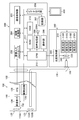
- FIG. 2 is another diagram showing the configuration of the endoscope system.
- FIG. 3 is a functional block diagram of the image processing unit.
- FIG. 4 is a diagram showing a configuration example of a convolutional neural network.
- FIG. 5 is a diagram showing a state of convolution processing by a filter.
- FIG. 6 is a diagram showing information recorded in the recording unit.
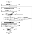
- FIG. 7 is a flowchart showing the procedure of the medical image processing method according to the first embodiment.
- FIG. 8 is a diagram showing an example of preferable highlighting for a real-time image.
- FIG. 9 is a diagram showing an example of unfavorable highlighting on a real-time image.
- FIG. 1 is a diagram showing the configuration of the endoscope system according to the first embodiment.
- FIG. 2 is another diagram showing the configuration of the endoscope system.
- FIG. 3 is a functional block diagram of the image
- FIG. 10 is a diagram showing a display example of part information.
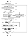
- FIG. 11 is another flowchart showing the procedure of the medical image processing method.
- FIG. 12 is a diagram showing an example of highlighting according to the elapsed time.
- FIG. 13 is another flowchart showing the procedure of the medical image processing method.
- FIG. 14 is a diagram showing how highlighting of a plurality of images displayed in a list is collectively turned on or off.
- FIG. 1 is an external view of an endoscope system 10 (medical image processing apparatus, endoscope system), and FIG. 2 is a block diagram showing a main configuration of the endoscope system 10.
- an endoscope system 10 includes an endoscope scope 100 (medical device, endoscope scope, endoscope body), endoscope processor device 200 (medical image processing device), light source. It is composed of a device 300 (light source device) and a monitor 400 (display device).
- An external device (not shown) for acquiring information on the observation site by electromagnetic waves or ultrasonic waves may be connected to the endoscope system 10.
- the endoscope scope 100 includes a hand operation unit 102 and an insertion unit 104 that is connected to the hand operation unit 102.
- An operator grasps and operates the hand operation unit 102, inserts the insertion unit 104 into the body of the subject (living body), and observes it.
- the hand operation unit 102 is provided with an air/water supply button 141, a suction button 142, a function button 143 to which various functions are assigned, and a photographing button 144 for accepting a photographing instruction operation (still image, moving image). ..
- the insertion section 104 is composed of a flexible section 112, a bending section 114, and a distal end hard section 116 in this order from the hand operation section 102 side. That is, the bending portion 114 is connected to the proximal end side of the distal end hard portion 116, and the flexible portion 112 is connected to the proximal end side of the bending portion 114.
- the proximal operation unit 102 is connected to the proximal end side of the insertion unit 104. The user can bend the bending portion 114 by operating the hand-side operating portion 102 to change the direction of the distal end hard portion 116 up, down, left or right.
- An imaging optical system 130, an illumination unit 123, a forceps opening 126, and the like are provided in the distal end hard section 116 (see FIGS. 1 and 2).
- white light and/or narrow band light (red narrow band light, green narrow band light, from the illumination lenses 123A and 123B of the illumination unit 123 is operated by operating the operation unit 208 (see FIG. 2).
- One or more of blue narrow band light and purple narrow band light can be irradiated.
- cleaning water is discharged from a water supply nozzle (not shown) to clean the photographing lens 132 (photographing lens, photographing unit) of the photographing optical system 130 and the illumination lenses 123A and 123B.
- a conduit (not shown) communicates with the forceps port 126 that opens at the distal end hard portion 116, and a treatment tool (not shown) for tumor removal or the like is inserted through this conduit and advances or retreats appropriately to the subject. They are able to take the necessary measures.
- a photographing lens 132 (imaging unit) is arranged on the distal end side end surface 116A of the distal rigid portion 116.
- a CMOS (Complementary Metal-Oxide Semiconductor) type image pickup device 134 image pickup device, image pickup unit
- a drive circuit 136 drive circuit 136
- AFE 138 Analog FrontEnd, image pickup unit
- the image signal is output by the element of.
- the image pickup element 134 is a color image pickup element, and is composed of a plurality of light receiving elements arranged in a matrix (two-dimensional arrangement) in a specific pattern arrangement (Bayer arrangement, X-Trans (registered trademark) arrangement, honeycomb arrangement, etc.). A plurality of pixels.
- Each pixel of the image sensor 134 includes a microlens, a red (R), a green (G), or a blue (B) color filter and a photoelectric conversion unit (photodiode or the like).
- the photographing optical system 130 can also generate a color image from pixel signals of three colors of red, green, and blue, or generate an image from pixel signals of any one color of red, green, and blue.
- the image pickup device 134 is a CMOS type image pickup device
- the image pickup device 134 may be a CCD (Charge Coupled Device) type.
- Each pixel of the image sensor 134 may further include a purple color filter corresponding to the purple light source 310V and/or an infrared filter corresponding to the infrared light source.
- the optical image of the subject is formed on the light receiving surface (image pickup surface) of the image pickup element 134 by the taking lens 132, converted into an electric signal, and output to the endoscope processor device 200 via a signal cable (not shown) to be an image. Converted to a signal. As a result, the endoscopic image is displayed on the monitor 400 connected to the endoscopic processor device 200.
- illumination lenses 123A and 123B of the illumination unit 123 are provided adjacent to the taking lens 132 on the distal end side end surface 116A of the distal rigid portion 116.
- An exit end of a light guide 170 which will be described later, is disposed inside the illumination lenses 123A and 123B, and the light guide 170 is inserted into the insertion section 104, the hand operation section 102, and the universal cable 106, and the light guide 170 The incident end is arranged in the light guide connector 108.
- the user performs imaging at a predetermined frame rate while inserting or removing the endoscope scope 100 (insertion unit 104) having the above-described configuration into or out of a living body as a subject (control of the imaging unit and the medical image acquisition unit 220). It is possible to sequentially capture in-vivo images.
- the light source device 300 includes an illumination light source 310, a diaphragm 330, a condenser lens 340, a light source controller 350, and the like, and makes observation light incident on the light guide 170.
- the light source 310 includes a red light source 310R, a green light source 310G, a blue light source 310B, and a violet light source 310V that respectively radiate red, green, blue, and violet narrowband light, and includes red, green, blue, and violet narrow light sources. Band light can be emitted.
- the illuminance of the observation light by the light source 310 is controlled by the light source control unit 350, and the illuminance of the observation light can be changed (increased or lowered) and the illumination can be stopped as necessary.
- the light source 310 can emit red, green, blue, and violet narrowband light in any combination. For example, it is possible to emit red, green, blue, and violet narrowband light at the same time to irradiate white light (normal light) as observation light, or to emit any one or two narrowband lights. Light (special light) can also be emitted.
- the light source 310 may further include an infrared light source that emits infrared light (an example of narrow band light). Further, white light or narrow band light may be irradiated as observation light by a light source that emits white light and a filter that transmits white light and each narrow band light.
- the light source 310 may be a white band light, a light source that emits light of a plurality of wavelength bands as white band light, or a light source that emits light of a specific wavelength band narrower than the white wavelength band.
- the specific wavelength band may be a visible blue band or a green band, or a visible red band.
- the specific wavelength band is the visible blue band or green band, it includes a wavelength band of 390 nm or more and 450 nm or less, or 530 nm or more and 550 nm or less, and peaks within the wavelength band of 390 nm or more and 450 nm or 530 nm or 550 nm or less It may have a wavelength.
- the specific wavelength band when the specific wavelength band is the visible red band, it includes a wavelength band of 585 nm or more and 615 nm or less, or 610 nm or more and 730 nm or less, and the light of the specific wavelength band is 585 nm or more and 615 nm or less or 610 nm or more. It may have a peak wavelength within a wavelength band of 730 nm or less.
- the light of the specific wavelength band described above includes a wavelength band having a different absorption coefficient between oxyhemoglobin and reduced hemoglobin, and the oxyhemoglobin and the reduced hemoglobin may have a peak wavelength in a different wavelength band absorption coefficient.
- the specific wavelength band includes a wavelength band of 400 ⁇ 10 nm, 440 ⁇ 10 nm, 470 ⁇ 10 nm, or 600 nm or more and 750 nm, and 400 ⁇ 10 nm, 440 ⁇ 10 nm, 470 ⁇ 10 nm, or 600 nm or more and 750 nm. You may have a peak wavelength in the following wavelength bands.
- the light generated by the light source 310 may include a wavelength band of 790 nm or more and 820 nm or less, or 905 nm or more and 970 nm or less, and may have a peak wavelength in a wavelength band of 790 nm or more and 820 nm or less or 905 nm or more and 970 nm or less.
- the light source 310 may include a light source that emits excitation light having a peak of 390 nm or more and 470 nm or less.
- a medical image medical image, in-vivo image
- a dye for fluorescence method fluorestin, acridine orange, etc.
- the light source type of the light source 310 (laser light source, xenon light source, LED light source (LED: Light-Emitting Diode), etc.), wavelength, presence/absence of a filter, etc. are preferably configured according to the type of the subject, the site, the purpose of observation, etc. In addition, it is preferable to combine and/or switch the wavelengths of the observation light according to the type of the subject, the site, the purpose of the observation, and the like during observation. When switching the wavelength, for example, by rotating a disk-shaped filter (rotary color filter) provided in front of the light source and provided with a filter that transmits or blocks light of a specific wavelength, the wavelength of the light to be irradiated is switched. Good.
- a disk-shaped filter rotary color filter
- the image pickup device used when implementing the present invention is not limited to the color image pickup device in which the color filter is arranged for each pixel like the image pickup device 134, and may be a monochrome image pickup device.
- a monochrome image pickup device it is possible to sequentially switch the wavelength of the observation light and pick up an image in a field sequential (color sequential) manner.
- the wavelength of the emitted observation light may be sequentially switched between (purple, blue, green, red), or broadband light (white light) may be emitted to rotate the rotary color filter (red, green, blue, purple, etc.).
- the wavelength of the observation light emitted by may be switched.
- the narrow band light may be infrared light (first narrow band light, second narrow band light) of two or more wavelengths having different wavelengths.
- the observation light emitted from the light source device 300 is transmitted to the illumination lenses 123A and 123B via the light guide 170, and the illumination lens.
- the observation range is irradiated from 123A and 123B.
- the configuration of the endoscope processor device 200 will be described with reference to FIG.
- the endoscope processor device 200 inputs the image signal output from the endoscope scope 100 via the image input controller 202, performs necessary image processing in the image processing unit 204, and outputs the image signal via the video output unit 206. To do. As a result, an endoscopic image (medical image) is displayed on the monitor 400 (display device). These processes are performed under the control of the CPU 210 (CPU: Central Processing Unit).
- the communication control unit 205 communicates with a hospital image system (HIS: Hospital Information System) (not shown), a hospital LAN (Local Area Network), and/or information about a medical image and a region of interest with an external system or network. Control communication.
- HIS Hospital Information System
- An image of the subject (endoscopic image, medical image, medical image), attention area information, display mode setting information, and the like are recorded in the recording unit 207 (recording device) (see FIG. 6 and related description). ..
- the voice processing unit 209 Under the control of the CPU 210 and the image processing unit 204, the voice processing unit 209 outputs a message (voice) regarding the detection of the attention area and the detection result from the speaker 209A.
- the ROM 211 (ROM: Read Only Memory) is a non-volatile storage element (non-temporary recording medium), and executes various image processing methods on the CPU 210 and/or the image processing unit 204 (medical image processing device, computer).
- the computer-readable code of the program to be stored is stored.
- a RAM 212 (RAM: Random Access Memory) is a storage element for temporary storage during various types of processing, and can also be used as a buffer when acquiring an image.
- the user can give an instruction to execute medical image processing and a condition necessary for execution through the operation unit 208, and the display control unit 228 (see FIG. 3) displays the screen at the time of these instructions and the detection result. Etc. can be displayed on the monitor 400.
- FIG. 3 is a functional block diagram of the image processing unit 204.
- the image processing unit 204 includes a medical image acquisition unit 220 (medical image acquisition unit), an information acquisition unit 222 (information acquisition unit), and a mode setting unit 226. (Aspect setting unit), display control unit 228 (display control unit), recording control unit 230 (recording control unit), reception unit 232 (reception unit), and first time information acquisition unit 234 (first The time information acquisition unit) and the second time information acquisition unit 235 (second time information acquisition unit).
- the information acquisition unit 222 includes a recognizer (detector 224A (detector), classifier 224B (classifier), and measuring device 224C (measuring device)). Details of medical image processing using these functions will be described later.
- the image processing unit 204 uses the above-described functions to calculate a feature amount of a medical image, a process of emphasizing or reducing a component of a specific frequency band, or emphasizing a specific target (region of interest, blood vessel of desired depth, etc.) It is possible to perform processing to make it inconspicuous.
- the image processing unit 204 is a special light that acquires a special light image having information of a specific wavelength band based on a normal light image obtained by irradiating light of a plurality of wavelength bands as white band light or white band light.
- An image acquisition unit may be provided.
- the signal of the specific wavelength band is converted into RGB (R: red, G: green, B: blue) or CMY (C: cyan, M: magenta, Y: yellow) color information included in the normal light image. It can be obtained by calculation based on Further, the image processing unit 204 includes a white band light, a normal light image obtained by irradiating light of a plurality of wavelength bands as white band light, and a special light image obtained by irradiating light of a specific wavelength band. A feature amount image generation unit that generates a feature amount image by calculation based on at least one of the above may be provided, and the feature amount image as a medical image (medical image) may be acquired and displayed. The above-mentioned processing is performed under the control of the CPU 210.
- the functions of the respective units of the image processing unit 204 described above can be realized by using various processors and recording media.
- the various processors include, for example, a CPU (Central Processing Unit) that is a general-purpose processor that executes software (programs) to realize various functions.
- the above-mentioned various processors include programmable logic devices (GPUs, Graphics Processing Units), FPGAs (Field Programmable Gate Arrays), etc. Programmable Logic Device (PLD) is also included.
- PLD Programmable Logic Device
- a configuration using a GPU is effective.
- a dedicated electric circuit which is a processor having a circuit configuration specifically designed to execute a specific process such as an ASIC (Application Specific Integrated Circuit), is also included in the various processors described above.
- each unit may be realized by one processor, or a plurality of processors of the same type or different types (for example, a plurality of FPGAs, a combination of CPU and FPGA, or a combination of CPU and GPU).
- a plurality of functions may be realized by one processor.
- a processor As an example of configuring a plurality of functions with a single processor, firstly, as represented by a computer, one processor is configured with a combination of one or more CPUs and software, and this processor has a plurality of functions. There are forms to realize. Secondly, there is a form in which a processor that realizes the functions of the entire system by one IC (Integrated Circuit) chip is used, as represented by a system on chip (SoC).
- SoC system on chip
- various functions are configured by using one or more of the various processors described above as a hardware structure.
- the hardware structure of these various processors is an electrical circuit in which circuit elements such as semiconductor elements are combined.
- These electric circuits may be electric circuits that realize the above-described functions by using logical sum, logical product, logical NOT, exclusive logical sum, and logical operation that combines these.
- the processor or electric circuit described above executes software (program), it can be read by a computer of the software (for example, various processors and electric circuits forming the image processing unit 204, and/or a combination thereof).
- the code is stored in a non-transitory recording medium such as a ROM 211 (ROM: Read Only Memory) and the computer refers to the software.
- the software stored in the non-temporary recording medium is a program for executing the medical image processing method according to the present invention and data used in execution (data used for specifying a display mode, detector 224A, classifier 224B). , And the parameters used in the measuring instrument 224C).
- the code may be recorded on a non-transitory recording medium such as various magneto-optical recording devices and semiconductor memories.
- a non-transitory recording medium such as various magneto-optical recording devices and semiconductor memories.
- the RAM 212 RAM: Random Access Memory
- EEPROM Electrically Erasable and Programmable Read Only Memory
- the recording unit 207 may be used as the “non-transitory recording medium”.
- the recognizer (detector 224A, classifier 224B, and measuring instrument 224C) described above is a trained model such as CNN (Convolutional Neural Network) and SVM (Support Vector Machine) (image set composed of images of a living body). Can be configured by using a model learned by using.
- CNN Convolutional Neural Network
- SVM Small Vector Machine
- FIG. 4 is a diagram showing an example of the layer structure of CNN.
- the CNN 562 includes an input layer 562A, an intermediate layer 562B, and an output layer 562C.
- the input layer 562A inputs the endoscopic image (medical image) acquired by the medical image acquisition unit 220 and outputs the feature amount.
- the middle layer 562B includes a convolutional layer 564 and a pooling layer 565, and inputs the feature amount output from the input layer 562A to calculate another feature amount.
- These layers have a structure in which a plurality of "nodes" are connected by "edges" and hold a plurality of weighting parameters.
- the value of the weight parameter changes as the learning progresses.
- the CNN 562 may include a fully-bonded layer 566 as in the example shown in part (b) of FIG.
- the layer configuration of the CNN 562 is not limited to the case where the convolutional layer 564 and the pooling layer 565 are repeated one by one, and any one of the layers (for example, the convolutional layer 564) may be continuously included. Further, a plurality of all-bonded layers 566 may be continuously included.
- the intermediate layer 562B calculates the feature amount by the convolution operation and the pooling process.
- the convolution calculation performed in the convolution layer 564 is a process of acquiring a feature map by a convolution calculation using a filter, and plays a role of feature extraction such as edge extraction from an image. By performing a convolution operation using this filter, a "feature map" of one channel (one sheet) is generated for one filter. The size of the "feature map” is downscaled by the convolution and becomes smaller as the convolution is performed on each layer.
- the pooling process performed in the pooling layer 565 is a process of reducing (or expanding) the feature map output by the convolution operation to obtain a new feature map, and the extracted features are not affected by translation or the like. Play a role in providing robustness to.
- the intermediate layer 562B can be configured by one or a plurality of layers that perform these processes.
- FIG. 5 is a schematic diagram showing a configuration example of the intermediate layer 562B of the CNN 562 shown in FIG.
- the convolution operation between the image set (a learning image set during learning and a recognition image set during recognition) including a plurality of medical images and the filter F 1 is performed.
- the image set is composed of N (N-channel) images each having an image size of H in the vertical direction and W in the horizontal direction.
- the images forming the image set are three-channel images of R (red), G (green), and B (blue).
- the filter F 1 to be convolved with this image set is a filter of 5 ⁇ 5 ⁇ N.
- a “feature map” of one channel (one sheet) is generated for one filter F 1 .
- the filter F 2 used in the second convolutional layer is, for example, a filter of size 3 (3 ⁇ 3), the filter size is 3 ⁇ 3 ⁇ M.
- the convolutional operations using the filters F 2 to F n are performed in the second to nth convolutional layers.
- the size of the "feature map" in the nth convolutional layer is smaller than the size of the "feature map” in the second convolutional layer because it is downscaled by the convolutional layer or pooling layer up to the preceding stage. Is.
- low-order feature extraction (edge extraction, etc.) is performed in the convolutional layer close to the input side, and higher-order feature extraction (features related to the shape, structure, etc. of the target object) is performed toward the output side. Extraction) is performed.
- segmentation is performed for the purpose of measurement or the like, upscaling is performed in the convolutional layer in the latter half part, and in the final convolutional layer, a “feature map” having the same size as the input image set is obtained.
- up-scaling is not essential when detecting an object, because position information may be output.
- the intermediate layer 562B may include a layer that performs batch normalization in addition to the convolutional layer 564 and the pooling layer 565.
- the batch normalization process is a process for normalizing the distribution of data in units of mini-batch at the time of learning, and has a role to accelerate learning, reduce dependency on an initial value, suppress overlearning, and the like.
- the output layer 562C is a layer that detects the position of the attention area reflected in the input medical image (normal light image, special light image) based on the characteristic amount output from the intermediate layer 562B and outputs the result. is there.
- the output layer 562C grasps the position of the attention area shown in the image at the pixel level from the “feature map” obtained from the intermediate layer 562B. That is, it is possible to detect whether each pixel of the endoscopic image belongs to the attention area and output the detection result.
- determination at the pixel level is not necessary, and the output layer 562C outputs the position information of the target object.
- the output layer 562C executes the discrimination (classification) regarding the lesion and outputs the discrimination result.
- the output layer 562C classifies endoscopic images into three categories of "neoplastic”, “non-neoplastic", and “other”, and distinguishes “neoplastic”, “non-neoplastic", and “other”. May be output as the three scores corresponding to (the total of the three scores is 100%), or the classification result may be output if the three scores can be clearly classified.
- the output layer 562C may or may not include the fully-bonded layer as the last one layer or a plurality of layers (see (b) part of FIG. 4). ..
- the output layer 562C outputs the measurement result of the attention area.
- the target region of interest can be segmented as described above, and then measured by the image processing unit 204 or the like based on the result. Further, it is possible to directly output the measurement value of the target attention area from the measuring instrument. When the measured value is directly output, the measured value itself is learned for the image, which is a regression problem of the measured value.
- the result output by the output layer 562C is compared with the correct answer of the recognition for the image set to calculate the loss (error), and the intermediate layer 562B is reduced so as to reduce the loss. It is preferable to perform the processing (error back propagation) of updating the weighting parameter in (3) from the layer on the output side to the layer on the input side.
- the recognizers may perform recognition (detection of a region of interest, etc.) by a method other than CNN.
- the attention area can be detected based on the feature amount of the pixels of the acquired medical image.
- the detector 224A divides the detection target image into, for example, a plurality of rectangular regions, sets each of the divided rectangular regions as a local region, and for each local region of the detection target image, the feature amount of the pixel in the local region ( For example, a hue) is calculated, and a local area having a specific hue is determined as a target area from each local area.
- classification and measurement may be performed based on the feature amount.
- all the detectors 224A, the classifiers 224B, and the measuring instruments 224C may be operated in parallel as the recognizers to switch the display result, or one or two recognizers may be used. It may be operated and the result may be displayed. Further, the endoscope system 10 may include one or two of the recognizers instead of all of the detector 224A, the classifier 224B, and the measuring instrument 224C.
- FIG. 6 is a diagram showing an example of information recorded in the recording unit 207.
- the endoscopic image 260 medical image
- the recognition result 262 detection result, classification result, measurement result
- display mode setting information 264 display mode when highlighting the attention area
- the recording control unit 230 records these pieces of information in association with each other.
- the reception unit 232 operates the user via the operation unit 208, and/or the display mode setting information 264 recorded in the recording unit 207 (for example, whether highlighting is turned on or off, or displayed).
- the conditions necessary for executing the medical image processing method are set on the basis of default display modes such as selection of figures and symbols to be performed (step S100: initial setting step).
- the image acquisition mode whether real-time image acquisition or non-real-time image acquisition
- characters, figures, symbols used for highlighting, and their colors are set.
- the conditions may be set or changed during execution of the following steps.
- “real-time” and “real-time image” are, for example, substantially a plurality of medical images taken at a predetermined frame rate in an ongoing examination or observation. Sequential acquisition without significant delay, and images so acquired. A case where image acquisition is slightly delayed compared to complete real time due to image transmission/reception, image processing, etc. is also included in “real time” and “real time image”.
- “non-real time” and “non-real time image” include, for example, a case where a plurality of medical images already recorded after the examination are sequentially acquired and displayed.
- the medical image acquisition unit 220 acquires an endoscopic image (medical image) taken in the living body of the subject (step S110: medical image acquisition step).
- the medical image acquisition unit 220 uses the imaging unit (the imaging lens 132, the imaging element 134, the AFE 138, etc.) of the endoscope 100 (medical device) to sequentially capture the inside of the living body that is the subject at a predetermined frame rate. Then, the endoscopic image can be acquired in real time (real-time image acquisition).
- the medical image acquisition unit 220 may acquire an endoscopic image that has already been captured and recorded in non-real time (acquisition of non-real time image).
- the endoscopic image 260 recorded in the recording unit 207 may be acquired, or the image may be acquired from an external device or system via the communication control unit 205.
- the site information indicating the observation site of the subject has already been acquired, even if an endoscopic image (medical image) taken with observation light in a wavelength band corresponding to the site indicated by the site information is acquired.
- an image taken with white light in the case of the stomach and an image taken with blue narrow band light in the case of the esophagus can be acquired.
- the display control unit 228 causes the monitor 400 to display the acquired endoscopic image.
- the detector 224A detects the attention area from the endoscopic image (medical image) (step S120: information acquisition step).
- the detector 224A grasps the position of the attention area shown in the image by the “feature map” at the pixel level (that is, the attention area is determined for each pixel of the endoscopic image. Whether or not it belongs) can be detected and the detection result can be output.
- regions of interest to be detected include polyps, cancer, large intestine diverticulum, inflammation, treatment scars (EMR: Endoscopic Mucosal Resection), ESD scars (ESD: Endoscopic Submucosal Dissection), clip locations, etc.), Examples include bleeding points, perforations, and vascular atypia.
- the classifier 224B and the measuring device 224C may perform classification and measurement in step S120.
- the endoscopic image (medical image) to be detected, classified, and measured may be a real-time image or a non-real-time image.
- the aspect setting unit 226 determines whether or not the image acquired in step S110 is a real-time image (step S130: determination step, aspect setting step). Based on this determination result, the mode setting unit 226 sets the display mode for the real-time image when it is a real-time image (YES in step S130) (step S140: mode setting step), and when it is a non-real-time image ( If NO in step S130, the display mode for the non-real-time image is set (step S150: mode setting step).
- the display control unit 228 displays the endoscopic image (medical image) on the monitor 400 (display device) according to the display mode (mode of highlighting the attention area) set in step S140 or S150 (step S160: display). Control step).
- FIG. 8 is a diagram showing a display example in the case of a real-time image (when highlighting is set to ON).
- Portions (b) and (c) of the figure show a state in which the attention area 802 in the endoscopic image 800 is highlighted by a graphic 804 and an arrow 806 (superimposed in the endoscopic image 800). These highlights directly indicate the position of the region of interest, but do not obstruct the observation of the mucosal structure because no graphic is superimposed on the region of interest itself.
- part (d) of the figure shows a state in which the frame 808 is displayed in a part outside the screen (outside the display range of the endoscopic image 800 in the display area of the monitor 400).
- FIG. 8A is a diagram (for reference) showing a state in which highlighting is not performed, and shows an endoscopic image 800 in which a region of interest 802 is shown.
- FIG. 9 is a diagram showing a display example in the case of a non-real-time image (when highlighting is set to ON).
- the part (a) of the figure shows a state in which the attention area 802 is filled, and the part (b) shows the endoscopic image 820 and the recognition result display image 822 on two screens, and the attention area 802 is displayed in the recognition result display image 822.
- a state in which a symbol 824 is displayed at a position corresponding to is shown.
- the display mode of FIG. 9 is not suitable for real-time display because it may hinder observation, but display after storage (including a case where an image recorded in the recording unit 207 or the like is acquired and displayed in non-real time) causes a problem.
- the display after storage observes the attention area in detail
- the display method in which the position of the attention area cannot be accurately grasped like the portions (d) to (f) of FIG. 8 is not preferable.
- a display size per image may be reduced in order to display a list of the image groups acquired during the inspection, more prominent emphasis processing is preferred. Therefore, the aspect as shown in FIG. 9 can be adopted.
- the display position and/or size of the observation screen may be changed. By doing so, it is possible to display an observation screen that fully utilizes the monitor size.
- FIGS. 8 and 9 are merely examples of display modes. 9 may be displayed in the case of a real-time image or may be displayed in the case of a non-real-time image as shown in FIG. Further, although FIG. 9 shows an example in which highlighting is turned on for a non-real-time image, highlighting may be turned off in response to a user operation or when a predetermined condition is satisfied. Also in the case of a real-time image, highlighting may be turned off in response to a user's operation or when a predetermined condition is satisfied. In addition to the display modes illustrated in FIGS. 8 and 9, color tone and gradation changes, frequency processing, and the like may be performed. Such setting of the display mode can be performed by the receiving unit 232 receiving a user operation (display mode setting operation) via the operation unit 208, and the mode setting unit 226 based on the setting operation.
- a user operation display mode setting operation
- mode setting unit 226 based on the setting operation.
- the mode setting unit 226 may set the display mode based on the classification result and the measurement result of the endoscopic image, and the display control unit 228 may perform the display according to the setting.
- the classification result of the endoscopic image can be set as “neoplastic”, “non-neoplastic”, and “other”, and a display mode using characters, figures, symbols, etc. can be set and displayed.
- You may change a color according to a classification result.
- the measurement result may be displayed as a numerical value such as “diameter 5 mm”, or a figure, a symbol, or the like indicating the size of the attention area may be displayed. Also in this case, the color may be changed according to the result.
- the number of monitors (display devices) in the endoscope system 10 is not particularly limited. Both the real-time image and the non-real-time image may be displayed on the monitor 400. In this case, for example, a real-time image can be displayed and a specific frame can be freeze-displayed according to a user's instruction or the like. Alternatively, a monitor for real-time images and a monitor for non-real-time images may be separately provided, and the images may be displayed on the respective monitors. When a separate monitor is provided, for example, a real-time image may be displayed on the monitor 400, and the image acquired by the inspection may be displayed on another monitor in non-real time when creating a report. Both aspects are included in "displaying an endoscopic image (medical image) on a display device".
- the display control unit 228 may display the part information (information indicating the part shown in the endoscopic image) together with the highlighted display of the endoscopic image.
- FIG. 10 is a diagram showing a display example of part information.
- Part (a) of FIG. 10 is an example in which part information 836 is displayed in characters (“gastric”) in addition to the frame 834 surrounding the region of interest 832 in the endoscopic image 830, and part (b) of FIG. Is an example in which site information is displayed in an endoscopic image 840 by an arrow 842A on a schematic diagram 842.
- the part information may be displayed with other icons, and the display mode (contents of characters and symbols, position, shape, color, etc.) may be changed according to the part.
- the site information can be acquired by analyzing an endoscopic image, input by a user, or an external device using electromagnetic waves or ultrasonic waves.
- the medical image acquisition unit 220 acquires the endoscopic image (medical image) captured by the observation light in the wavelength band corresponding to the part shown in the endoscopic image, and the display control unit 228 determines the observation light in the wavelength band.
- the result of recognition of the medical image photographed in (3) may be displayed on the monitor 400 (display device). For example, an image taken with white light (normal light) in the case of the stomach and an image taken with special light (blue narrow band light) such as BLI (Blue Laser Imaging: registered trademark) in the case of the esophagus can be recognized. Can be offered.
- LCI Linked Color Imaging: registered trademark
- image processing in the case of LCI, the saturation difference and hue difference of colors close to the mucous membrane color are extended. You may use.
- the image processing according to the part can be performed by the image processing unit 204.
- the recording control unit 230 (recording control unit) records the endoscopic image and the information of the attention area in the recording unit 207 as the endoscopic image 260 and the recognition result 262, respectively (step S170: recording control step). If the classification or measurement is performed in step S120, the result is recorded. Further, when the endoscopic image is subjected to image processing, the processed endoscopic image can be recorded, and the display mode setting information 264 is recorded together with the endoscopic image 260 and the recognition result 262. Good. These pieces of information are preferably recorded in association with each other.
- the image processing unit 204 determines whether to end the process (step S180), and if the process is to be continued (NO in step S180), the process returns to step S110, and the above-described process is performed for the next frame, for example.
- the endoscope system 10 can highlight medical images according to real-time characteristics. Further, since the medical image and the information of the attention area are associated with each other and recorded in the recording device (the information is recorded without being superimposed on the image), when the medical image and the information are used afterwards (in the case of a non-real time image) Can be displayed in a display mode according to the purpose of observation and the wishes of the user.
- FIG. 11 is a flowchart showing a display mode setting process based on the information of the elapsed time. Since steps other than steps S152 to S156 are the same as those in FIG. 7, detailed description thereof will be omitted.
- the first time information acquisition unit 234 calculates the elapsed time during which the endoscopic image (medical image) showing the same region of interest is displayed on the monitor 400 (display device) ( First elapsed time) information is acquired (step S152: time information acquisition step), and the mode setting unit 226 determines whether or not the first elapsed time is equal to or greater than a threshold value (step S154: determination). Step).
- the first time information acquisition unit 234 can acquire (calculate) information on the elapsed time based on, for example, the frame rate of shooting and the number of frames in which the same attention area is reflected.
- the mode setting unit 226 resets the display mode based on the information of the first elapsed time (step S156: mode setting step), When the elapsed time of 1 is less than the threshold value (NO in step S154), the display mode is maintained.
- FIG. 12 is a diagram showing a state in which the display mode is reset according to the first elapsed time.
- a graphic 804A surrounding the attention area 802 is displayed by a dotted line, and the degree of emphasis is low.
- the mode setting unit 226 and the display control unit 228 can switch, for example, the state of the part (b) of FIG. 8 (the graphic 804 is displayed by a solid line) and the state of FIG. 12 according to the first elapsed time.
- the first elapsed time when the first elapsed time is short, it can be displayed as shown in part (b) of FIG. 8 to raise the degree of emphasis to call attention, and thereafter, the degree of emphasis can be lowered as shown in FIG.
- the pattern may be displayed in the opposite pattern depending on the user's operation or the purpose of observation. Further, instead of changing the line type of the figure as shown in FIGS. 8 and 12, the shape and size of the figure and the symbol, the color and the brightness may be changed.
- highlighting may be turned on or off depending on the elapsed time, or the degree of emphasis may be increased (or decreased). For example, highlighting may be turned off at the beginning of detection and then turned on (or the degree of emphasis may be increased with the first elapsed time), or vice versa (or the degree of emphasis may be decreased with the first elapsed time). ) Is OK. Further, it may be repeatedly turned on and off at predetermined time intervals.
- Such processing is performed, for example, when the endoscopic images are sequentially acquired and displayed at a predetermined frame rate and the elapsed time (first elapsed time) is the state in which the same region of interest appears in a plurality of frames. It can be applied when the display mode is set accordingly.
- the display mode when the attention area is highlighted may be set based on information on the elapsed time during which the same endoscopic image is displayed.
- the processing in this case can be performed in the same manner as the flowchart of FIG.
- the second time information acquisition unit 235 acquires information on the elapsed time (second elapsed time) during which the same endoscopic image is displayed on the monitor 400 (display device). Then, (step S152: time information acquisition step), the mode setting unit 226 determines whether the second elapsed time is equal to or greater than the threshold value (step S154: determination step).
- the mode setting unit 226 resets the display mode based on the information of the second elapsed time (step S156: mode setting step), When the elapsed time of 2 is less than the threshold value (NO in step S154), the display mode is maintained.
- the display mode can be the same as that based on the first elapsed time.
- Such processing is performed by changing the display mode in accordance with the elapsed time (second elapsed time) during which a specific image is continuously displayed, for example, when the endoscope image is continuously observed by freeze display or the like. It can be applied when setting.
- the display control unit 228 causes the monitor 400 (display device) to display a list of a plurality of medical images recorded in the recording unit 207 (recording device) (step S160: display control step).
- step S160 display control step.
- Part (a) of FIG. 14 shows a state in which six images are displayed with the highlighting being off, and the attention area 802 is detected in the endoscopic images 850 and 852.
- the mode setting unit 226 determines whether there is a change operation (step S162: determination step).
- the mode setting unit 226 can determine that “there is a change operation” when the user performs a change operation via the operation unit 208 and the reception unit 232 receives the operation.
- the mode setting unit 226 sets the highlighted mode for the plurality of medical images displayed in a list to the common mode. For example, highlighting of a plurality of endoscopic images (medical images) is collectively set to on (or off).
- the display control unit 228 redisplays the displayed endoscopic images in the changed display mode (common mode) (step S164: display control step).
- the display control unit 228 displays frames 854 and 856 with respect to the endoscopic images 850 and 852 in which the attention area 802 is detected, for example, as shown in part (b) of FIG. 14 (endoscopic images 850 and 852). For the other images, the frame is not displayed because the attention area has not been detected).
- the "common aspect” is that "a frame surrounding the entire image is displayed for the image showing the region of interest". With such a display, the user can easily select an image in which the region of interest is reflected (that is, an image that requires close examination) from a large number of images after the inspection.
- the emphasis method may be changed between the list display and the single display. For example, when displaying a list, a frame that surrounds the entire image is displayed as in the portion (b) of FIG. 14, and when displaying alone, a figure that surrounds the portion of the attention area 802 as in the portion (b) of FIG. 8 and FIG. Or a frame can be displayed.
- This display mode is displayed as shown in part (b) of FIG. 14 because only the information “the area of interest is reflected” or “not reflected” is sufficient when the list is displayed, and when the single display is performed, the area of interest in the image is displayed. Since information on the position of is required, it is displayed as shown in part (b) of FIG.
- the medical image analysis processing unit detects an attention area, which is an attention area, based on the feature amount of the pixels of the medical image,
- the medical image analysis result acquisition unit is a medical image processing apparatus that acquires the analysis result of the medical image analysis processing unit.
- the medical image analysis processing unit based on the feature amount of the pixels of the medical image, detects the presence or absence of a target of interest
- the medical image analysis result acquisition unit is a medical image processing apparatus that acquires the analysis result of the medical image analysis processing unit.
- the analysis result is a medical image processing apparatus which is either or both of an attention area which is an attention area included in a medical image and the presence or absence of an attention object.
- the medical image processing apparatus in which the medical image is a white band light or a normal light image obtained by irradiating light in a plurality of wavelength bands as white band light.
- Medical images are images obtained by irradiating light in a specific wavelength band, The medical image processing device in which the specific wavelength band is narrower than the white wavelength band.
- the specific wavelength band includes a wavelength band of 390 nm or more and 450 nm or less or 530 nm or more and 550 nm or less, and the light of the specific wavelength band has a peak wavelength in the wavelength band of 390 nm or more and 450 nm or less or 530 nm or more and 550 nm or less.
- Image processing device includes a wavelength band of 390 nm or more and 450 nm or less or 530 nm or more and 550 nm or less, and the light of the specific wavelength band has a peak wavelength in the wavelength band of 390 nm or more and 450 nm or less or 530 nm or more and 550 nm or less.
- the specific wavelength band includes a wavelength band of 585 nm or more and 615 nm or less or 610 nm or more and 730 nm or less, and the light of the specific wavelength band has a peak wavelength within a wavelength band of 585 nm or more and 615 nm or less or 610 nm or more and 730 nm or less.
- Image processing device includes a wavelength band of 585 nm or more and 615 nm or less or 610 nm or more and 730 nm or less, and the light of the specific wavelength band has a peak wavelength within a wavelength band of 585 nm or more and 615 nm or less or 610 nm or more and 730 nm or less.
- the specific wavelength band includes a wavelength band having a different absorption coefficient between oxyhemoglobin and reduced hemoglobin, and the light of a specific wavelength band has a peak wavelength in a wavelength band having a different absorption coefficient between oxyhemoglobin and reduced hemoglobin.
- the specific wavelength band includes 400 ⁇ 10 nm, 440 ⁇ 10 nm, 470 ⁇ 10 nm, or a wavelength band of 600 nm or more and 750 nm or less, and the light of the specific wavelength band is 400 ⁇ 10 nm, 440 ⁇ 10 nm, 470 ⁇ .
- a medical image processing apparatus having a peak wavelength in a wavelength band of 10 nm or 600 nm or more and 750 nm or less.
- Medical images are in-vivo images of the inside of a living body,
- the in-vivo image is a medical image processing apparatus that has information on the fluorescence emitted by the fluorescent substance in the living body.
- the fluorescence is a medical image processing apparatus obtained by irradiating the living body with excitation light having a peak of 390 to 470 nm.
- Medical images are in-vivo images of the inside of a living body, The medical image processing device in which the specific wavelength band is the wavelength band of infrared light.
- the specific wavelength band includes a wavelength band of 790 nm or more and 820 nm or less or 905 nm or more and 970 nm or less, and the light of the specific wavelength band has a peak wavelength in a wavelength band of 790 nm or more and 820 nm or less or 905 nm or more and 970 nm or less. Processing equipment.
- the medical image acquisition unit acquires a special light image having information of a specific wavelength band based on a white band light or a normal light image obtained by irradiating light of a plurality of wavelength bands as the white band light. Equipped with an optical image acquisition unit, Medical image processing device where medical images are special light images.
- a feature amount image generation unit for generating a feature amount image
- a medical image processing device in which a medical image is a feature amount image.
- Appendix 19 A medical image processing apparatus according to any one of appendices 1 to 18, An endoscope that irradiates at least one of light in a white wavelength band or light in a specific wavelength band to obtain an image, An endoscopic device provided with.
- Appendix 20 A diagnostic support device comprising the medical image processing device according to any one of appendices 1 to 18.
- Appendix 21 A medical service support apparatus comprising the medical image processing apparatus according to any one of appendices 1 to 18.
- Endoscope system 100 endoscope scope 102 Hand control unit 104 Insert 106 universal cable 108 Light guide connector 112 Soft part 114 curved part 116 Tip hard part 116A Tip side end face 123 Illuminator 123A Lighting lens 123B Lighting lens 126 Forceps mouth 130 Photographic optical system 132 shooting lens 134 Image sensor 136 drive circuit 138 AFE 141 Air/water button 142 Suction button 143 Function button 144 shooting button 170
- Light guide 200 processors 202 Image input controller 204 image processing unit 205 communication control unit 206 Video output section 207 Recording section 208 Operation part 209 Voice processing unit 209A speaker 210 CPU 211 ROM 212 RAM 220 Medical Image Acquisition Department 222 Information acquisition unit 224A detector 224B classifier 224C measuring instrument 226 Mode setting unit 228 Display control unit 230 Recording control unit 232 Reception Department 234 First time information acquisition unit 235 Second time information acquisition unit 260 endoscopic image 262 recognition results H.264 display mode setting information 300 light source device 310 light source
Landscapes
- Health & Medical Sciences (AREA)
- Life Sciences & Earth Sciences (AREA)
- Surgery (AREA)
- Nuclear Medicine, Radiotherapy & Molecular Imaging (AREA)
- Biomedical Technology (AREA)
- Optics & Photonics (AREA)
- Pathology (AREA)
- Radiology & Medical Imaging (AREA)
- Biophysics (AREA)
- Engineering & Computer Science (AREA)
- Physics & Mathematics (AREA)
- Heart & Thoracic Surgery (AREA)
- Medical Informatics (AREA)
- Molecular Biology (AREA)
- Animal Behavior & Ethology (AREA)
- General Health & Medical Sciences (AREA)
- Public Health (AREA)
- Veterinary Medicine (AREA)
- Endoscopes (AREA)
Abstract
本発明は、医療画像をリアルタイム性に応じて強調表示することができる医療画像処理装置、内視鏡システム、及び医療画像処理方法を提供することを目的とする。本発明の一の態様に係る医療画像処理装置は、医療画像処理装置は、医療画像を取得する医療画像取得部と、医療画像における注目領域の情報を取得する情報取得部と、情報に基づいて、注目領域の強調表示を、医療画像がリアルタイムで取得されたリアルタイム画像であるか非リアルタイムで取得された非リアルタイム画像であるかに応じた表示態様に設定する態様設定部と、医療画像を設定された表示態様で表示装置に表示させる表示制御部と、医療画像と情報とを関連付けて記録装置に記録させる記録制御部と、を備える。
Description
本発明は医療画像の強調表示を行う医療画像処理装置、内視鏡システム、及び医療画像処理方法に関する。
医師等のユーザが医療画像の観察あるいは診断を行う際の支援として、画像の強調や表示態様の変更を行うことが知られている。例えば、特許文献1には、注目領域のサイズや数に応じてアラート画像を表示することが記載されている。
医療画像の観察あるいは診断を行う場合、画像の性質によって好ましい強調表示の態様が異なるので、適宜切り替える必要がある。例えば、スクリーニング検査中にリアルタイムで取得した画像で検出された注目領域に図形等を重畳することで、ユーザに病変検出の報知を行うことができる。一方、ユーザは検査中に発見された病変の画像を保存し、レポート作成や研究に利用する。また、保存した画像を必要に応じ再度表示させて観察する。このように非リアルタイムで取得した画像を表示させる場合、図形等の重畳表示は観察や診断の妨げになり得るので、注目領域の強調表示をリアルタイム表示時と異なる態様に設定することが好ましい。しかしながら、上述した特許文献1にこのような事情が考慮されていない。
このように、従来の技術では医療画像をリアルタイム性に応じて適切に強調表示することが困難であった。
本発明はこのような事情に鑑みてなされたもので、医療画像をリアルタイム性に応じて強調表示することができる医療画像処理装置、内視鏡システム、及び医療画像処理方法を提供することを目的とする。
上述した目的を達成するため、本発明の第1の態様に係る医療画像処理装置は、医療画像を取得する医療画像取得部と、医療画像における注目領域の情報を取得する情報取得部と、情報に基づいて、注目領域の強調表示を、医療画像がリアルタイムで取得されたリアルタイム画像であるか非リアルタイムで取得された非リアルタイム画像であるかに応じた表示態様に設定する態様設定部と、医療画像を設定された表示態様で表示装置に表示させる表示制御部と、医療画像と情報とを関連付けて記録装置に記録させる記録制御部と、を備える。
第1の態様に係る医療画像処理装置は、医療画像をリアルタイム性(リアルタイムで取得されたリアルタイム画像であるか非リアルタイムで取得された非リアルタイム画像であるか)に応じて強調表示させることができる。また、医療画像と注目領域の情報とを関連付けて記録装置に記録させる(情報を画像に重畳させずに記録する)ので、医療画像及び情報を事後的に使用する場合(非リアルタイム画像の場合)も観察の目的やユーザの希望に応じた表示態様で表示させることができる。
第1の態様において、「表示態様の設定」には強調表示をオンとオフのいずれに設定するか、及び注目領域の情報をどのように表示させるかが含まれる。情報の表示は文字、数字、図形、記号、及びそれらの組み合わせにより行うことができ、色彩を付してもよい。
第1の態様及び以下の各対応において、「リアルタイム」、「リアルタイム画像」には、例えば、進行中の検査や観察において、決められたフレームレートで撮影された複数の医療画像を実質的な遅延なしで順次取得し表示すること、及びそのように順次表示される画像が含まれる。画像の送受信や画像処理等により完全なリアルタイムよりも画像の取得や表示が僅かに遅延している場合も「リアルタイム」、「リアルタイム画像」に含まれるものとする。これに対し「非リアルタイム」、「非リアルタイム画像」には、例えば、検査中及び検査後に静止画を取得して表示する場合が含まれる。
第1の態様及び以下の各態様において、表示装置の数は特に限定されない。同一の表示装置にリアルタイム画像と非リアルタイム画像の両方を表示させてもよい。この場合、例えばリアルタイム画像を表示し、ユーザの指示等に応じて特定のフレームをフリーズ表示させることができる。また、リアルタイム画像用の表示装置と非リアルタイム画像用の表示装置を別個に設け、それぞれの表示装置に画像を表示させてもよい。別個のモニタを設ける場合、例えばある表示装置にリアルタイム画像を表示させ、レポート作成の際等に、検査で取得された画像を非リアルタイムで別の表示装置に表示させてもよい。いずれの態様も、「医療画像を表示装置に表示させる」に含まれる。
第1の態様に係る医療画像処理装置は、例えば医療画像処理システムのプロセッサとして実現することができるが、このような態様に限定されるものではない。なお、「医療画像」とは診断、治療、計測等を目的として人体等の生体を撮影、計測等した結果として得られた画像をいい、例えば内視鏡画像、超音波画像、CT画像(CT:Computed Tomography)、MRI画像(MRI:Magnetic Resonance Imaging)を挙げることができる。医療画像は医用画像ともいう。
第2の態様に係る医療画像処理装置は第1の態様において、態様設定部は、医療画像がリアルタイム画像である場合、注目領域の強調表示をオンまたはオフに設定する。第2の態様によれば、強調表示をオンに設定する場合は注目領域の情報を強調表示によりリアルタイムで報知することができ、病変等の見落としを防止することができる。一方、強調表示等が診断の妨げになる場合はオフに設定してもよい。オンとオフのいずれに設定するかをユーザの操作に基づいて決定してもよいし、ユーザの操作によらずに決定してもよい。
第3の態様に係る医療画像処理装置は第1の態様において、態様設定部は、医療画像が非リアルタイム画像である場合、注目領域の強調表示をオンまたはオフに設定する。情報が重畳された状態の画像はレポートや診断には適さず、一方、注目領域の情報は検査後に画像を見返す場合に必要となる(見落とし防止、研究用途等)。第3の態様では、このような事情を考慮し非リアルタイム画像の場合に強調表示をオンまたはオフにするので、画像の使用目的に応じた強調表示を行うことができる。オンとオフのいずれに設定するかはユーザの操作に応じて行うことができ、これによりユーザは所望の表示態様で医療画像を表示させることができる。
第4の態様に係る医療画像処理装置は第1から第3の態様のいずれか1つにおいて、医療画像取得部は、記録装置に記録された医療画像を非リアルタイム画像として取得し、情報取得部は、非リアルタイム画像に関連付けて記録された情報を取得する。医療画像取得部は、ネットワークを介して接続された記録装置から医療画像を取得してもよい。
第5の態様に係る医療画像処理装置は第1から第4の態様のいずれか1つにおいて、医療画像から注目領域を検出する検出器を備え、情報取得部は、検出器の検出結果から情報を取得する。検出の対象となる医療画像はリアルタイム画像でもよいし、非リアルタイム画像でもよい。なお第5の態様において、検出器は学習済みモデルにより構成することができる。
第6の態様に係る医療画像処理装置は第1から第5の態様のいずれか1つにおいて、医療画像の分類を行う分類器を備え、情報取得部は、分類器の分類結果から情報を取得する。分類の対象となる医療画像はリアルタイム画像でもよいし、非リアルタイム画像でもよい。なお第6の態様において、分類器は学習済みモデルにより構成することができる。
第7の態様に係る医療画像処理装置は第1から第6の態様のいずれか1つにおいて、医療画像の計測を行う計測器を備え、情報取得部は、計測器の計測結果から情報を取得する。計測の対象となる医療画像はリアルタイム画像でもよいし、非リアルタイム画像でもよい。なお第7の態様において、計測器は学習済みモデルにより構成することができる。
第8の態様に係る医療画像処理装置は第1から第7の態様のいずれか1つにおいて、ユーザによる表示態様の設定操作を受け付ける受付部を備え、態様設定部は受け付けた設定操作に基づいて表示態様を設定する。第8の態様によれば、ユーザは医療画像を所望の表示態様(注目領域の強調表示の態様)で表示させることができる。
第9の態様に係る医療画像処理装置は第1から第8の態様のいずれか1つにおいて、同一の注目領域が映っている医療画像が表示装置に表示されている第1の経過時間の情報を取得する第1の時間情報取得部を備え、態様設定部は第1の経過時間の情報に基づいて表示態様を設定する。第9の態様は、例えばリアルタイム画像を決められたフレームレートで順次取得、表示させる場合において、同一の注目領域が複数のフレームに映っている状態の経過時間(第1の経過時間)に応じて表示態様を設定する場合に適用することができる。第9の態様では、第1の経過時間に応じて表示態様を変える(オン、オフの切り替えを含む)ことができる。
第10の態様に係る医療画像処理装置は第1から第9の態様のいずれか1つにおいて、同一の医療画像が表示装置に表示されている第2の経過時間の情報を取得する第2の時間情報取得部を備え、態様設定部は第2の経過時間の情報に基づいて表示態様を設定する。第10の態様は、例えば非リアルタイム画像をフリーズ表示(固定表示)により観察している場合において、画像を表示してからの経過時間(第2の経過時間)に応じて表示態様を設定する場合に適用することができる。第10の態様では、第2の経過時間に応じて表示態様を変える(オン、オフの切り替えを含む)ことができる。
第11の態様に係る医療画像処理装置は第1から第10の態様のいずれか1つにおいて、表示制御部は、記録装置に記録された複数の医療画像を表示装置に一覧表示させ、態様設定部は、一覧表示した複数の医療画像に対する強調表示の態様を共通した態様に設定する。複数の医療画像を一覧表示する場合に画像ごとに表示態様を設定するのでは操作が煩わしいが、第11の態様では強調表示の態様を共通した態様に設定するので、操作が簡単である。この設定は、ユーザの操作に応じて行うことができる。
第12の態様に係る医療画像処理装置は第11の態様において、共通した態様は、複数の医療画像に対する強調表示のオンまたはオフである。第12の態様によれば、複数の医療画像に対する強調表示を一括してオンまたはオフにすることができる。
第13の態様に係る医療画像処理装置は第1から第12の態様のいずれか1つにおいて、態様設定部は、医療画像が、進行中の検査又は進行中の観察において順次取得されている画像の場合に、医療画像をリアルタイム画像と判断する。第13の態様は、進行中の検査又は進行中の観察に適用することができる。
第14の態様に係る医療画像処理装置は第1から第13の態様のいずれか1つにおいて、更に、記録部を有し、態様設定部は、医療画像が、記録部に記録済みの画像の場合に、医療画像を前記非リアルタイム画像と判断する。第14の態様は、記録部に記録済みの医療画像に適用することができる。
第15の態様に係る医療画像処理装置は第1から第14の態様のいずれか1つにおいて、更に、通信制御部を有し、態様設定部は、医療画像が、通信制御部を介して取得された画像の場合に、医療画像を非リアルタイム画像と判断する。第15の態様は、通信制御部を介して取得された医療画像に適用することができる。
第13の態様に係る医療画像処理装置は第1から第12の態様のいずれか1つにおいて、態様設定部は、医療画像が、進行中の検査又は進行中の観察において順次取得されている画像の場合に、医療画像をリアルタイム画像と判断する。第13の態様は、進行中の検査又は進行中の観察に適用することができる。
第14の態様に係る医療画像処理装置は第1から第13の態様のいずれか1つにおいて、更に、記録部を有し、態様設定部は、医療画像が、記録部に記録済みの画像の場合に、医療画像を前記非リアルタイム画像と判断する。第14の態様は、記録部に記録済みの医療画像に適用することができる。
第15の態様に係る医療画像処理装置は第1から第14の態様のいずれか1つにおいて、更に、通信制御部を有し、態様設定部は、医療画像が、通信制御部を介して取得された画像の場合に、医療画像を非リアルタイム画像と判断する。第15の態様は、通信制御部を介して取得された医療画像に適用することができる。
上述した目的を達成するため、本発明の第16の態様に係る内視鏡システムは、第1から第15の態様のいずれか1つに係る医療画像処理装置と、表示装置と、被検体に挿入される内視鏡スコープであって、医療画像を撮影する撮影部を有する内視鏡スコープと、を備える。第16の態様に係る内視鏡システムは、第1から第15の態様のいずれか1つに係る医療画像処理装置を備えるので、医療画像のリアルタイム性に応じて強調処理を行うことができる。リアルタイム画像は内視鏡スコープの撮影部により撮影することができる。なお、第1の態様について上述したのと同様に、第16の態様において表示装置の数は特に限定されない。同一の表示装置にリアルタイム画像と非リアルタイム画像の両方を表示させてもよいし、リアルタイム画像用の表示装置と非リアルタイム画像用の表示装置を別個に設け、それぞれの表示装置に画像を表示させてもよい。
上述した目的を達成するため、本発明の第17の態様に係る医療画像処理方法は、医療画像を取得する医療画像取得ステップと、医療画像における注目領域の情報を取得する情報取得ステップと、情報に基づいて、注目領域の強調表示を、医療画像がリアルタイムで取得されたリアルタイム画像であるか非リアルタイムで取得された非リアルタイム画像であるかに応じた表示態様に設定する態様設定ステップと、医療画像を設定された表示態様で表示装置に表示させる表示制御ステップと、医療画像と情報とを関連付けて記録装置に記録させる記録制御ステップと、を有する。第17の態様によれば、第1の態様と同様に、医療画像をリアルタイム性に応じて強調表示することができる。
第18の態様に係る医療画像処理方法は、第2から第15の態様と同様の構成(ステップ)をさらに含んでいてもよい。また、これら態様の医療画像処理方法を医療画像処理装置あるいはコンピュータに実行させるプログラム、並びにそのプログラムのコンピュータ読み取り可能なコードを記録した非一時的記録媒体も本発明の態様として挙げることができる。
以上説明したように、本発明に係る医療画像処理装置、内視鏡システム、及び医療画像処理方法によれば、医療画像をリアルタイム性に応じて強調表示することができる
以下、添付図面を参照しつつ、本発明に係る医療画像処理装置、内視鏡システム、及び医療画像処理方法の実施形態について詳細に説明する。
<第1の実施形態>
<内視鏡システムの構成>
図1は、内視鏡システム10(医療画像処理装置、内視鏡システム)の外観図であり、図2は内視鏡システム10の要部構成を示すブロック図である。図1,2に示すように、内視鏡システム10は、内視鏡スコープ100(医療機器、内視鏡スコープ、内視鏡本体)、内視鏡プロセッサ装置200(医療画像処理装置)、光源装置300(光源装置)、及びモニタ400(表示装置)から構成される。電磁波や超音波により観察部位の情報を取得するための外部デバイス(不図示)を内視鏡システム10に接続してもよい。
<内視鏡システムの構成>
図1は、内視鏡システム10(医療画像処理装置、内視鏡システム)の外観図であり、図2は内視鏡システム10の要部構成を示すブロック図である。図1,2に示すように、内視鏡システム10は、内視鏡スコープ100(医療機器、内視鏡スコープ、内視鏡本体)、内視鏡プロセッサ装置200(医療画像処理装置)、光源装置300(光源装置)、及びモニタ400(表示装置)から構成される。電磁波や超音波により観察部位の情報を取得するための外部デバイス(不図示)を内視鏡システム10に接続してもよい。
<内視鏡スコープの構成>
内視鏡スコープ100は、手元操作部102と、この手元操作部102に連設される挿入部104とを備える。術者(ユーザ)は手元操作部102を把持して操作し、挿入部104を被検体(生体)の体内に挿入して観察する。また、手元操作部102には送気送水ボタン141、吸引ボタン142、及び各種の機能を割り付けられる機能ボタン143、及び撮影指示操作(静止画像、動画像)を受け付ける撮影ボタン144が設けられている。挿入部104は、手元操作部102側から順に、軟性部112、湾曲部114、先端硬質部116で構成されている。すなわち、先端硬質部116の基端側に湾曲部114が接続され、湾曲部114の基端側に軟性部112が接続される。挿入部104の基端側に手元操作部102が接続される。ユーザは、手元操作部102を操作することにより湾曲部114を湾曲させて先端硬質部116の向きを上下左右に変えることができる。先端硬質部116には、撮影光学系130、照明部123、鉗子口126等が設けられる(図1,2参照)。
内視鏡スコープ100は、手元操作部102と、この手元操作部102に連設される挿入部104とを備える。術者(ユーザ)は手元操作部102を把持して操作し、挿入部104を被検体(生体)の体内に挿入して観察する。また、手元操作部102には送気送水ボタン141、吸引ボタン142、及び各種の機能を割り付けられる機能ボタン143、及び撮影指示操作(静止画像、動画像)を受け付ける撮影ボタン144が設けられている。挿入部104は、手元操作部102側から順に、軟性部112、湾曲部114、先端硬質部116で構成されている。すなわち、先端硬質部116の基端側に湾曲部114が接続され、湾曲部114の基端側に軟性部112が接続される。挿入部104の基端側に手元操作部102が接続される。ユーザは、手元操作部102を操作することにより湾曲部114を湾曲させて先端硬質部116の向きを上下左右に変えることができる。先端硬質部116には、撮影光学系130、照明部123、鉗子口126等が設けられる(図1,2参照)。
観察、処置の際には、操作部208(図2参照)の操作により、照明部123の照明用レンズ123A,123Bから白色光及び/または狭帯域光(赤色狭帯域光、緑色狭帯域光、青色狭帯域光、及び紫色狭帯域光のうち1つ以上)を照射することができる。また、送気送水ボタン141の操作により図示せぬ送水ノズルから洗浄水が放出されて、撮影光学系130の撮影レンズ132(撮影レンズ、撮影部)、及び照明用レンズ123A,123Bを洗浄することができる。先端硬質部116で開口する鉗子口126には不図示の管路が連通しており、この管路に腫瘍摘出等のための図示せぬ処置具が挿通されて、適宜進退して被検体に必要な処置を施せるようになっている。
図1,2に示すように、先端硬質部116の先端側端面116Aには撮影レンズ132(撮影部)が配設されている。撮影レンズ132の奥にはCMOS(Complementary Metal-Oxide Semiconductor)型の撮像素子134(撮像素子、撮影部)、駆動回路136、AFE138(AFE:Analog Front End、撮影部)が配設されて、これらの要素により画像信号を出力する。撮像素子134はカラー撮像素子であり、特定のパターン配列(ベイヤー配列、X-Trans(登録商標)配列、ハニカム配列等)でマトリクス状に配置(2次元配列)された複数の受光素子により構成される複数の画素を備える。撮像素子134の各画素はマイクロレンズ、赤(R)、緑(G)、または青(B)のカラーフィルタ及び光電変換部(フォトダイオード等)を含んでいる。撮影光学系130は、赤,緑,青の3色の画素信号からカラー画像を生成することもできるし、赤,緑,青のうち任意の1色または2色の画素信号から画像を生成することもできる。なお、第1の実施形態では撮像素子134がCMOS型の撮像素子である場合について説明するが、撮像素子134はCCD(Charge Coupled Device)型でもよい。なお、撮像素子134の各画素は紫色光源310Vに対応した紫色カラーフィルタ、及び/または赤外光源に対応した赤外用フィルタをさらに備えていてもよい。
被検体の光学像は撮影レンズ132により撮像素子134の受光面(撮像面)に結像されて電気信号に変換され、不図示の信号ケーブルを介して内視鏡プロセッサ装置200に出力されて映像信号に変換される。これにより、内視鏡プロセッサ装置200に接続されたモニタ400に内視鏡画像が表示される。
また、先端硬質部116の先端側端面116Aには、撮影レンズ132に隣接して照明部123の照明用レンズ123A、123Bが設けられている。照明用レンズ123A,123Bの奥には、後述するライトガイド170の射出端が配設され、このライトガイド170が挿入部104、手元操作部102、及びユニバーサルケーブル106に挿通され、ライトガイド170の入射端がライトガイドコネクタ108内に配置される。
ユーザは、上述した構成の内視鏡スコープ100(挿入部104)を被検体である生体内に挿入または抜去しながら決められたフレームレートで撮影を行う(撮影部及び医療画像取得部220の制御により行うことができる)ことにより、生体内の画像を順次撮影することができる。
<光源装置の構成>
図2に示すように、光源装置300は、照明用の光源310、絞り330、集光レンズ340、及び光源制御部350等から構成されており、観察光をライトガイド170に入射させる。光源310は、それぞれ赤色、緑色、青色、紫色の狭帯域光を照射する赤色光源310R、緑色光源310G、青色光源310B、及び紫色光源310Vを備えており、赤色、緑色、青色、及び紫色の狭帯域光を照射することができる。光源310による観察光の照度は光源制御部350により制御され、必要に応じて観察光の照度を変更する(上げる、または下げる)こと、及び照明を停止することができる。
図2に示すように、光源装置300は、照明用の光源310、絞り330、集光レンズ340、及び光源制御部350等から構成されており、観察光をライトガイド170に入射させる。光源310は、それぞれ赤色、緑色、青色、紫色の狭帯域光を照射する赤色光源310R、緑色光源310G、青色光源310B、及び紫色光源310Vを備えており、赤色、緑色、青色、及び紫色の狭帯域光を照射することができる。光源310による観察光の照度は光源制御部350により制御され、必要に応じて観察光の照度を変更する(上げる、または下げる)こと、及び照明を停止することができる。
光源310は赤色、緑色、青色、及び紫色の狭帯域光を任意の組合せで発光させることができる。例えば、赤色、緑色、青色、及び紫色の狭帯域光を同時に発光させて白色光(通常光)を観察光として照射することもできるし、いずれか1つもしくは2つを発光させることで狭帯域光(特殊光)を照射することもできる。光源310は、赤外光(狭帯域光の一例)を照射する赤外光源をさらに備えていてもよい。また、白色光を照射する光源と、白色光及び各狭帯域光を透過させるフィルタとにより、白色光または狭帯域光を観察光として照射してもよい。
<光源の波長帯域>
光源310は白色帯域の光、または白色帯域の光として複数の波長帯域の光を発生する光源でもよいし、白色の波長帯域よりも狭い特定の波長帯域の光を発生する光源でもよい。特定の波長帯域は、可視域の青色帯域もしくは緑色帯域、あるいは可視域の赤色帯域であってもよい。特定の波長帯域が可視域の青色帯域もしくは緑色帯域である場合、390nm以上450nm以下、または530nm以上550nm以下の波長帯域を含み、かつ、390nm以上450nm以下または530nm以上550nm以下の波長帯域内にピーク波長を有していてもよい。また、特定の波長帯域が可視域の赤色帯域である場合、585nm以上615nm以下、または610nm以上730nm以下、の波長帯域を含み、かつ、特定の波長帯域の光は、585nm以上615nm以下または610nm以上730nm以下の波長帯域内にピーク波長を有していてもよい。
光源310は白色帯域の光、または白色帯域の光として複数の波長帯域の光を発生する光源でもよいし、白色の波長帯域よりも狭い特定の波長帯域の光を発生する光源でもよい。特定の波長帯域は、可視域の青色帯域もしくは緑色帯域、あるいは可視域の赤色帯域であってもよい。特定の波長帯域が可視域の青色帯域もしくは緑色帯域である場合、390nm以上450nm以下、または530nm以上550nm以下の波長帯域を含み、かつ、390nm以上450nm以下または530nm以上550nm以下の波長帯域内にピーク波長を有していてもよい。また、特定の波長帯域が可視域の赤色帯域である場合、585nm以上615nm以下、または610nm以上730nm以下、の波長帯域を含み、かつ、特定の波長帯域の光は、585nm以上615nm以下または610nm以上730nm以下の波長帯域内にピーク波長を有していてもよい。
上述した特定の波長帯域の光は、酸化ヘモグロビンと還元ヘモグロビンとで吸光係数が異なる波長帯域を含み、かつ、酸化ヘモグロビンと還元ヘモグロビンとで吸光係数が異なる波長帯域にピーク波長を有していてもよい。この場合、特定の波長帯域は、400±10nm、440±10nm、470±10nm、または、600nm以上750nmの波長帯域を含み、かつ、400±10nm、440±10nm、470±10nm、または600nm以上750nm以下の波長帯域にピーク波長を有していてもよい。
また、光源310が発生する光は790nm以上820nm以下、または905nm以上970nm以下の波長帯域を含み、かつ、790nm以上820nm以下または905nm以上970nm以下の波長帯域にピーク波長を有していてもよい。
また、光源310は、ピークが390nm以上470nm以下である励起光を照射する光源を備えていてもよい。この場合、被検体(生体)内の蛍光物質が発する蛍光の情報を有する医療画像(医用画像、生体内画像)を取得することができる。蛍光画像を取得する場合は、蛍光法用色素剤(フルオレスチン、アクリジンオレンジ等)を使用してもよい。
光源310の光源種類(レーザ光源、キセノン光源、LED光源(LED:Light-Emitting Diode)等)、波長、フィルタの有無等は被写体の種類、部位、観察の目的等に応じて構成することが好ましく、また観察の際は被写体の種類、部位、観察の目的等に応じて観察光の波長を組合せ及び/または切り替えることが好ましい。波長を切り替える場合、例えば光源の前方に配置され特定波長の光を透過または遮光するフィルタが設けられた円板状のフィルタ(ロータリカラーフィルタ)を回転させることにより、照射する光の波長を切り替えてもよい。
また、本発明を実施する際に用いる撮像素子は撮像素子134のように各画素に対しカラーフィルタが配設されたカラー撮像素子に限定されるものではなく、モノクロ撮像素子でもよい。モノクロ撮像素子を用いる場合、観察光の波長を順次切り替えて面順次(色順次)で撮像することができる。例えば出射する観察光の波長を(紫色、青色、緑色、赤色)の間で順次切り替えてもよいし、広帯域光(白色光)を照射してロータリカラーフィルタ(赤色、緑色、青色、紫色等)により出射する観察光の波長を切り替えてもよい。また、1または複数の狭帯域光(緑色、青色、紫色等)を照射してロータリカラーフィルタ(緑色、青色、紫色等)により出射する観察光の波長を切り替えてもよい。狭帯域光は波長の異なる2波長以上の赤外光(第1狭帯域光、第2狭帯域光)でもよい。
ライトガイドコネクタ108(図1,2参照)を光源装置300に連結することにより、光源装置300から照射された観察光がライトガイド170を介して照明用レンズ123A、123Bに伝送され、照明用レンズ123A、123Bから観察範囲に照射される。
<プロセッサの構成>
図2に基づき内視鏡プロセッサ装置200の構成を説明する。内視鏡プロセッサ装置200は、内視鏡スコープ100から出力される画像信号を画像入力コントローラ202を介して入力し、画像処理部204で必要な画像処理を行ってビデオ出力部206を介して出力する。これによりモニタ400(表示装置)に内視鏡画像(医療画像)が表示される。これらの処理はCPU210(CPU:Central Processing Unit)の制御下で行われる。通信制御部205は、図示せぬ病院内システム(HIS:Hospital Information System)や病院内LAN(Local Area Network)、及び/または外部のシステムやネットワークとの間で医療画像や注目領域の情報についての通信制御を行う。記録部207(記録装置)には、被検体の画像(内視鏡画像、医療画像、医用画像)、注目領域情報、表示態様設定情報等が記録される(図6及び関連する記載を参照)。音声処理部209は、CPU210及び画像処理部204の制御により、注目領域の検出及び検出結果に関するメッセージ(音声)をスピーカ209Aから出力する。
図2に基づき内視鏡プロセッサ装置200の構成を説明する。内視鏡プロセッサ装置200は、内視鏡スコープ100から出力される画像信号を画像入力コントローラ202を介して入力し、画像処理部204で必要な画像処理を行ってビデオ出力部206を介して出力する。これによりモニタ400(表示装置)に内視鏡画像(医療画像)が表示される。これらの処理はCPU210(CPU:Central Processing Unit)の制御下で行われる。通信制御部205は、図示せぬ病院内システム(HIS:Hospital Information System)や病院内LAN(Local Area Network)、及び/または外部のシステムやネットワークとの間で医療画像や注目領域の情報についての通信制御を行う。記録部207(記録装置)には、被検体の画像(内視鏡画像、医療画像、医用画像)、注目領域情報、表示態様設定情報等が記録される(図6及び関連する記載を参照)。音声処理部209は、CPU210及び画像処理部204の制御により、注目領域の検出及び検出結果に関するメッセージ(音声)をスピーカ209Aから出力する。
また、ROM211(ROM:Read Only Memory)は不揮発性の記憶素子(非一時的記録媒体)であり、各種の画像処理方法をCPU210及び/または画像処理部204(医療画像処理装置、コンピュータ)に実行させるプログラムのコンピュータ読み取り可能なコードが記憶されている。RAM212(RAM:Random Access Memory)は各種処理の際の一時記憶用の記憶素子であり、また画像取得時のバッファとしても使用することができる。
なお、ユーザは操作部208を介して医療画像処理の実行指示や実行に必要な条件の指定を行うことができ、表示制御部228(図3参照)はこれら指示の際の画面、検出の結果等をモニタ400に表示させることができる。
<画像処理部の機能>
図3は画像処理部204の機能ブロック図である。画像処理部204は、医療画像取得部220(医療画像取得部)と、情報取得部222(情報取得部)と、態様設定部226
(態様設定部)と、表示制御部228(表示制御部)と、記録制御部230(記録制御部)と、受付部232(受付部)と、第1の時間情報取得部234(第1の時間情報取得部)と、第2の時間情報取得部235(第2の時間情報取得部)と、を備える。情報取得部222は、認識器(検出器224A(検出器)、分類器224B(分類器)、及び計測器224C(計測器))を備える。これらの機能を用いた医療画像処理については、詳細を後述する。
図3は画像処理部204の機能ブロック図である。画像処理部204は、医療画像取得部220(医療画像取得部)と、情報取得部222(情報取得部)と、態様設定部226
(態様設定部)と、表示制御部228(表示制御部)と、記録制御部230(記録制御部)と、受付部232(受付部)と、第1の時間情報取得部234(第1の時間情報取得部)と、第2の時間情報取得部235(第2の時間情報取得部)と、を備える。情報取得部222は、認識器(検出器224A(検出器)、分類器224B(分類器)、及び計測器224C(計測器))を備える。これらの機能を用いた医療画像処理については、詳細を後述する。
画像処理部204は、上述した機能により、医療画像の特徴量の算出、特定の周波数帯域の成分を強調または低減する処理、特定の対象(注目領域、所望の深さの血管等)を強調または目立たなくする処理を行うことができる。画像処理部204は、白色帯域の光、または白色帯域の光として複数の波長帯域の光を照射して得る通常光画像に基づいて特定の波長帯域の情報を有する特殊光画像を取得する特殊光画像取得部を備えていてもよい。この場合、特定の波長帯域の信号は、通常光画像に含まれるRGB(R:赤、G:緑、B:青)あるいはCMY(C:シアン、M:マゼンタ、Y:イエロー)の色情報に基づく演算により得ることができる。また、画像処理部204は、白色帯域の光、または白色帯域の光として複数の波長帯域の光を照射して得る通常光画像と、特定の波長帯域の光を照射して得る特殊光画像との少なくとも一方に基づく演算によって特徴量画像を生成する特徴量画像生成部を備え、医療画像(医用画像)としての特徴量画像を取得及び表示してもよい。なお、上述した処理はCPU210の制御下で行われる。
<各種のプロセッサによる機能の実現>
上述した画像処理部204の各部の機能は、各種のプロセッサ(processor)及び記録媒体を用いて実現できる。各種のプロセッサには、例えばソフトウェア(プログラム)を実行して各種の機能を実現する汎用的なプロセッサであるCPU(Central Processing Unit)が含まれる。また、上述した各種のプロセッサには、画像処理に特化したプロセッサであるGPU(Graphics Processing Unit)、FPGA(Field Programmable Gate Array)などの製造後に回路構成を変更可能なプロセッサであるプログラマブルロジックデバイス(Programmable Logic Device:PLD)も含まれる。本発明のように画像の学習や認識を行う場合は、GPUを用いた構成が効果的である。さらに、ASIC(Application Specific Integrated Circuit)などの特定の処理を実行させるために専用に設計された回路構成を有するプロセッサである専用電気回路なども上述した各種のプロセッサに含まれる。
上述した画像処理部204の各部の機能は、各種のプロセッサ(processor)及び記録媒体を用いて実現できる。各種のプロセッサには、例えばソフトウェア(プログラム)を実行して各種の機能を実現する汎用的なプロセッサであるCPU(Central Processing Unit)が含まれる。また、上述した各種のプロセッサには、画像処理に特化したプロセッサであるGPU(Graphics Processing Unit)、FPGA(Field Programmable Gate Array)などの製造後に回路構成を変更可能なプロセッサであるプログラマブルロジックデバイス(Programmable Logic Device:PLD)も含まれる。本発明のように画像の学習や認識を行う場合は、GPUを用いた構成が効果的である。さらに、ASIC(Application Specific Integrated Circuit)などの特定の処理を実行させるために専用に設計された回路構成を有するプロセッサである専用電気回路なども上述した各種のプロセッサに含まれる。
各部の機能は1つのプロセッサにより実現されてもよいし、同種または異種の複数のプロセッサ(例えば、複数のFPGA、あるいはCPUとFPGAの組み合わせ、またはCPUとGPUの組み合わせ)で実現されてもよい。また、複数の機能を1つのプロセッサで実現してもよい。複数の機能を1つのプロセッサで構成する例としては、第1に、コンピュータに代表されるように、1つ以上のCPUとソフトウェアの組合せで1つのプロセッサを構成し、このプロセッサが複数の機能として実現する形態がある。第2に、システムオンチップ(System On Chip:SoC)などに代表されるように、システム全体の機能を1つのIC(Integrated Circuit)チップで実現するプロセッサを使用する形態がある。このように、各種の機能は、ハードウェア的な構造として、上述した各種のプロセッサを1つ以上用いて構成される。さらに、これらの各種のプロセッサのハードウェア的な構造は、より具体的には、半導体素子などの回路素子を組み合わせた電気回路(circuitry)である。これらの電気回路は、論理和、論理積、論理否定、排他的論理和、及びこれらを組み合わせた論理演算を用いて上述した機能を実現する電気回路であってもよい。
上述したプロセッサあるいは電気回路がソフトウェア(プログラム)を実行する際は、実行するソフトウェアのコンピュータ(例えば、画像処理部204を構成する各種のプロセッサや電気回路、及び/またはそれらの組み合わせ)で読み取り可能なコードをROM211(ROM:Read Only Memory)等の非一時的記録媒体に記憶しておき、コンピュータがそのソフトウェアを参照する。非一時的記録媒体に記憶しておくソフトウェアは、本発明に係る医療画像処理方法を実行するためのプログラム及び実行に際して用いられるデータ(表示態様の特定に用いられるデータ、検出器224A、分類器224B、及び計測器224Cで用いられるパラメータ等)を含む。ROM211ではなく各種の光磁気記録装置、半導体メモリ等の非一時的記録媒体にコードを記録してもよい。ソフトウェアを用いた処理の際には例えばRAM212(RAM:Random Access Memory)が一時的記憶領域として用いられ、また例えば不図示のEEPROM(Electronically Erasable and Programmable Read Only Memory)に記憶されたデータを参照することもできる。「非一時的記録媒体」として記録部207を用いてもよい。
<学習済みモデルによる認識器>
上述した認識器(検出器224A、分類器224B,及び計測器224C)は、CNN(Convolutional Neural Network)、SVM(Support Vector Machine)等の学習済みモデル(生体を撮影した画像から構成される画像セットを用いて学習したモデル)を用いて構成することができる。以下、認識器をCNNにより構成する場合の層構成について説明する。
上述した認識器(検出器224A、分類器224B,及び計測器224C)は、CNN(Convolutional Neural Network)、SVM(Support Vector Machine)等の学習済みモデル(生体を撮影した画像から構成される画像セットを用いて学習したモデル)を用いて構成することができる。以下、認識器をCNNにより構成する場合の層構成について説明する。
<CNNの層構成の例>
図4はCNNの層構成の例を示す図である。図4の(a)部分に示す例では、CNN562は入力層562Aと、中間層562Bと、出力層562Cとを含む。入力層562Aは医療画像取得部220が取得した内視鏡画像(医療画像)を入力して特徴量を出力する。中間層562Bは畳み込み層564及びプーリング層565を含み、入力層562Aが出力する特徴量を入力して他の特徴量を算出する。これらの層は複数の「ノード」が「エッジ」で結ばれた構造となっており、複数の重みパラメータを保持している。重みパラメータの値は、学習が進むにつれて変化していく。CNN562は、図4の(b)部分に示す例のように全結合層566を含んでいてもよい。CNN562の層構成は畳み込み層564とプーリング層565とが1つずつ繰り返される場合に限らず、いずれかの層(例えば、畳み込み層564)が複数連続して含まれていてもよい。また、全結合層566が複数連続して含まれていてもよい。
図4はCNNの層構成の例を示す図である。図4の(a)部分に示す例では、CNN562は入力層562Aと、中間層562Bと、出力層562Cとを含む。入力層562Aは医療画像取得部220が取得した内視鏡画像(医療画像)を入力して特徴量を出力する。中間層562Bは畳み込み層564及びプーリング層565を含み、入力層562Aが出力する特徴量を入力して他の特徴量を算出する。これらの層は複数の「ノード」が「エッジ」で結ばれた構造となっており、複数の重みパラメータを保持している。重みパラメータの値は、学習が進むにつれて変化していく。CNN562は、図4の(b)部分に示す例のように全結合層566を含んでいてもよい。CNN562の層構成は畳み込み層564とプーリング層565とが1つずつ繰り返される場合に限らず、いずれかの層(例えば、畳み込み層564)が複数連続して含まれていてもよい。また、全結合層566が複数連続して含まれていてもよい。
<中間層における処理>
中間層562Bは、畳み込み演算及びプーリング処理によって特徴量を算出する。畳み込み層564で行われる畳み込み演算はフィルタを使用した畳み込み演算により特徴マップを取得する処理であり、画像からのエッジ抽出等の特徴抽出の役割を担う。このフィルタを用いた畳み込み演算により、1つのフィルタに対して1チャンネル(1枚)の「特徴マップ」が生成される。「特徴マップ」のサイズは、畳み込みによりダウンスケーリングされ、各層で畳み込みが行われるにつれて小さくなって行く。プーリング層565で行われるプーリング処理は畳み込み演算により出力された特徴マップを縮小(または拡大)して新たな特徴マップとする処理であり、抽出された特徴が、平行移動などによる影響を受けないようにロバスト性を与える役割を担う。中間層562Bは、これらの処理を行う1または複数の層により構成することができる。
中間層562Bは、畳み込み演算及びプーリング処理によって特徴量を算出する。畳み込み層564で行われる畳み込み演算はフィルタを使用した畳み込み演算により特徴マップを取得する処理であり、画像からのエッジ抽出等の特徴抽出の役割を担う。このフィルタを用いた畳み込み演算により、1つのフィルタに対して1チャンネル(1枚)の「特徴マップ」が生成される。「特徴マップ」のサイズは、畳み込みによりダウンスケーリングされ、各層で畳み込みが行われるにつれて小さくなって行く。プーリング層565で行われるプーリング処理は畳み込み演算により出力された特徴マップを縮小(または拡大)して新たな特徴マップとする処理であり、抽出された特徴が、平行移動などによる影響を受けないようにロバスト性を与える役割を担う。中間層562Bは、これらの処理を行う1または複数の層により構成することができる。
図5は、図4に示したCNN562の中間層562Bの構成例を示す模式図である。中間層562Bの最初(1番目)の畳み込み層では、複数の医療画像により構成される画像セット(学習時は学習用画像セット、認識時は認識用画像セット)とフィルタF1との畳み込み演算が行われる。画像セットは、縦がH、横がWの画像サイズを有するN枚(Nチャンネル)の画像により構成される。通常光画像を入力する場合、画像セットを構成する画像はR(赤色),G(緑色),B(青色)の3チャンネルの画像である。この画像セットと畳み込み演算されるフィルタF1は、画像セットがNチャンネル(N枚)であるため、例えばサイズ5(5×5)のフィルタの場合、フィルタサイズは5×5×Nのフィルタになる。このフィルタF1を用いた畳み込み演算により、1つのフィルタF1に対して1チャンネル(1枚)の「特徴マップ」が生成される。2番目の畳み込み層で使用されるフィルタF2は、例えばサイズ3(3×3)のフィルタの場合、フィルタサイズは3×3×Mになる。
1番目の畳み込み層と同様に、2番目からn番目の畳み込み層ではフィルタF2~Fnを用いた畳み込み演算が行われる。n番目の畳み込み層における「特徴マップ」のサイズが、2番目の畳み込み層における「特徴マップ」のサイズよりも小さくなっているのは、前段までの畳み込み層またはプーリング層によりダウンスケーリングされているからである。
中間層562Bの層のうち、入力側に近い畳み込み層では低次の特徴抽出(エッジの抽出等)が行われ、出力側に近づくにつれて高次の特徴抽出(対象物の形状、構造等に関する特徴の抽出)が行われる。なお、計測等を目的としてセグメンテーションを行う場合は後半部分の畳み込み層でアップスケーリングされ、最後の畳み込み層では、入力した画像セットと同じサイズの「特徴マップ」が得られる。一方、物体検出を行う場合は位置情報を出力すればよいのでアップスケーリングは必須ではない。
なお、中間層562Bは畳み込み層564及びプーリング層565の他にバッチノーマライゼーションを行う層を含んでいてもよい。バッチノーマライゼーション処理は学習を行う際のミニバッチを単位としてデータの分布を正規化する処理であり、学習を速く進行させる、初期値への依存性を下げる、過学習を抑制する等の役割を担う。
<出力層における処理>
出力層562Cは、中間層562Bから出力された特徴量に基づき、入力された医療画像(通常光画像、特殊光画像)に映っている注目領域の位置検出を行ってその結果を出力する層である。セグメンテーションを行う場合、出力層562Cは、中間層562Bから得られる「特徴マップ」により、画像に写っている注目領域の位置を画素レベルで把握する。すなわち、内視鏡画像の画素ごとに注目領域に属するか否かを検出し、その検出結果を出力することができる。一方、物体検出を行う場合は画素レベルでの判断は必要なく、出力層562Cが対象物の位置情報を出力する。
出力層562Cは、中間層562Bから出力された特徴量に基づき、入力された医療画像(通常光画像、特殊光画像)に映っている注目領域の位置検出を行ってその結果を出力する層である。セグメンテーションを行う場合、出力層562Cは、中間層562Bから得られる「特徴マップ」により、画像に写っている注目領域の位置を画素レベルで把握する。すなわち、内視鏡画像の画素ごとに注目領域に属するか否かを検出し、その検出結果を出力することができる。一方、物体検出を行う場合は画素レベルでの判断は必要なく、出力層562Cが対象物の位置情報を出力する。
分類器224Bの場合、出力層562Cは病変に関する鑑別(分類)を実行して鑑別結果を出力する。例えば、出力層562Cは内視鏡画像を「腫瘍性」、「非腫瘍性」、「その他」の3つのカテゴリに分類し、鑑別結果として「腫瘍性」、「非腫瘍性」及び「その他」に対応する3つのスコア(3つのスコアの合計は100%)として出力してもよいし、3つのスコアから明確に分類できる場合には分類結果を出力してもよい。なお鑑別結果を出力する場合、出力層562Cが最後の1層または複数の層として全結合層を含んでいてもよいし(図4の(b)部分を参照)、含んでいなくてもよい。
計測器224Cの場合、出力層562Cは注目領域の計測結果を出力する。CNNによって計測を行う場合は、対象となる注目領域を例えば上述のようにセグメンテーションしてからその結果を基に画像処理部204等で計測することができる。また、対象となる注目領域の計測値を計測器から直接出力することもできる。計測値を直接出力させる場合、画像に対し計測値そのものを学習させるので、計測値の回帰問題となる。
上述した構成のCNNを用いる場合、学習の過程において、出力層562Cが出力する結果と画像セットに対する認識の正解とを比較して損失(誤差)を計算し、損失が小さくなるように中間層562Bにおける重みパラメータを出力側の層から入力側の層に向けて更新していく処理(誤差逆伝播)を行うことが好ましい。
<CNN以外の手法による認識>
認識器(検出器224A、分類器224B,及び計測器224C)は、CNN以外の手法により認識(注目領域の検出等)を行ってもよい。例えば、取得した医療画像の画素の特徴量に基づいて注目領域を検出することができる。この場合、例えば検出器224Aは検出対象画像を例えば複数の矩形領域に分割し、分割した各矩形領域を局所領域として設定し、検出対象画像の局所領域ごとに局所領域内の画素の特徴量(例えば色相)を算出し、各局所領域の中から特定の色相を有する局所領域を注目領域として決定する。同様に、特徴量に基づく分類や計測を行ってもよい。
認識器(検出器224A、分類器224B,及び計測器224C)は、CNN以外の手法により認識(注目領域の検出等)を行ってもよい。例えば、取得した医療画像の画素の特徴量に基づいて注目領域を検出することができる。この場合、例えば検出器224Aは検出対象画像を例えば複数の矩形領域に分割し、分割した各矩形領域を局所領域として設定し、検出対象画像の局所領域ごとに局所領域内の画素の特徴量(例えば色相)を算出し、各局所領域の中から特定の色相を有する局所領域を注目領域として決定する。同様に、特徴量に基づく分類や計測を行ってもよい。
なお、内視鏡システム10において、認識器として検出器224A、分類器224B,及び計測器224Cの全てを並行して動作させて表示結果を切り替えてもよいし、1つまたは2つの認識器を動作させて結果を表示してもよい。また、内視鏡システム10は検出器224A、分類器224B,及び計測器224Cの全てではなく、これら認識器のうち1つまたは2つを備えていてもよい。
<記録部に記録される情報>
図6は、記録部207に記録される情報の例を示す図である。図6の例では、内視鏡画像260(医療画像)、認識結果262(検出結果、分類結果、計測結果)、表示態様設定情報264(注目領域の強調表示を行う際の表示態様)が記録される。他の情報を併せて記録してもよい。記録制御部230は、これらの情報を関連付けて記録する。
図6は、記録部207に記録される情報の例を示す図である。図6の例では、内視鏡画像260(医療画像)、認識結果262(検出結果、分類結果、計測結果)、表示態様設定情報264(注目領域の強調表示を行う際の表示態様)が記録される。他の情報を併せて記録してもよい。記録制御部230は、これらの情報を関連付けて記録する。
<医療画像処理方法>
上述した構成の内視鏡システム10における医療画像処理方法について、図7のフローチャートを参照して説明する。
上述した構成の内視鏡システム10における医療画像処理方法について、図7のフローチャートを参照して説明する。
<初期設定>
受付部232(受付部)は、操作部208を介したユーザの操作、及び/または記録部207に記録された表示態様設定情報264(例えば、強調表示をオンにするかオフにするか、表示する図形や記号の選択等、デフォルトの表示態様)に基づいて、医療画像処理方法の実行に必要な条件を設定する(ステップS100:初期設定ステップ)。例えば、画像取得モード(リアルタイム画像の取得か非リアルタイム画像の取得か)、強調表示に用いる文字、図形、記号やその色彩等を設定する。なお、以下のステップの実行中に条件設定や変更を行ってもよい。
受付部232(受付部)は、操作部208を介したユーザの操作、及び/または記録部207に記録された表示態様設定情報264(例えば、強調表示をオンにするかオフにするか、表示する図形や記号の選択等、デフォルトの表示態様)に基づいて、医療画像処理方法の実行に必要な条件を設定する(ステップS100:初期設定ステップ)。例えば、画像取得モード(リアルタイム画像の取得か非リアルタイム画像の取得か)、強調表示に用いる文字、図形、記号やその色彩等を設定する。なお、以下のステップの実行中に条件設定や変更を行ってもよい。
なお、第1の実施形態及び他の態様において、「リアルタイム」、「リアルタイム画像」には、例えば、進行中の検査や観察において、決められたフレームレートで撮影された複数の医療画像を実質的な遅延なしで順次取得すること、及びそのようにして取得された画像が含まれる。画像の送受信や画像処理等により完全なリアルタイムよりも画像の取得が僅かに遅延している場合も「リアルタイム」、「リアルタイム画像」に含まれるものとする。これに対し「非リアルタイム」、「非リアルタイム画像」には、例えば、検査が終了し既に記録されている複数の医療画像を順次取得して表示する場合が含まれる。
<内視鏡画像の取得>
医療画像取得部220(医療画像取得部)は、被検体の生体内で撮影された内視鏡画像(医療画像)を取得する(ステップS110:医療画像取得ステップ)。医療画像取得部220は、内視鏡スコープ100(医療機器)の撮影部(撮影レンズ132、撮像素子134、AFE138等)により、被検体である生体の内部をあらかじめ決められたフレームレートで順次撮影して内視鏡画像をリアルタイムに取得することができる(リアルタイム画像の取得)。
医療画像取得部220(医療画像取得部)は、被検体の生体内で撮影された内視鏡画像(医療画像)を取得する(ステップS110:医療画像取得ステップ)。医療画像取得部220は、内視鏡スコープ100(医療機器)の撮影部(撮影レンズ132、撮像素子134、AFE138等)により、被検体である生体の内部をあらかじめ決められたフレームレートで順次撮影して内視鏡画像をリアルタイムに取得することができる(リアルタイム画像の取得)。
医療画像取得部220は、既に撮影され記録された内視鏡画像を非リアルタイムで取得してもよい(非リアルタイム画像の取得)。例えば、記録部207に記録された内視鏡画像260を取得してもよいし、通信制御部205を介して外部の装置やシステムから画像を取得してもよい。また、被検体の観察部位を示す部位情報が既に取得されている場合は、部位情報が示す部位に応じた波長帯域の観察光で撮影された内視鏡画像(医療画像)を取得してもよい。例えば、胃の場合は白色光で撮影された画像、食道の場合は青色狭帯域光で撮影された画像を取得することができる。表示制御部228は、取得した内視鏡画像をモニタ400に表示させる。
<注目領域の検出>
検出器224Aは、内視鏡画像(医療画像)から注目領域を検出する(ステップS120:情報取得ステップ)。注目領域の検出を行う場合、上述したように、検出器224Aは「特徴マップ」により画像に映っている注目領域の位置を画素レベルで把握(すなわち、内視鏡画像の画素ごとに注目領域に属するか否かを検出)し、その検出結果を出力することができる。検出する注目領域(関心領域)の例としては、ポリープ、癌、大腸憩室、炎症、治療痕(EMR瘢痕(EMR:Endoscopic Mucosal Resection)、ESD瘢痕(ESD:Endoscopic Submucosal Dissection)、クリップ箇所等)、出血点、穿孔、血管異型性などを挙げることができる。検出の場合と同様に、ステップS120において分類器224B、計測器224Cにより分類や計測を行ってもよい。なお、検出、分類、計測の対象となる内視鏡画像(医療画像)はリアルタイム画像でもよいし、非リアルタイム画像でもよい。
検出器224Aは、内視鏡画像(医療画像)から注目領域を検出する(ステップS120:情報取得ステップ)。注目領域の検出を行う場合、上述したように、検出器224Aは「特徴マップ」により画像に映っている注目領域の位置を画素レベルで把握(すなわち、内視鏡画像の画素ごとに注目領域に属するか否かを検出)し、その検出結果を出力することができる。検出する注目領域(関心領域)の例としては、ポリープ、癌、大腸憩室、炎症、治療痕(EMR瘢痕(EMR:Endoscopic Mucosal Resection)、ESD瘢痕(ESD:Endoscopic Submucosal Dissection)、クリップ箇所等)、出血点、穿孔、血管異型性などを挙げることができる。検出の場合と同様に、ステップS120において分類器224B、計測器224Cにより分類や計測を行ってもよい。なお、検出、分類、計測の対象となる内視鏡画像(医療画像)はリアルタイム画像でもよいし、非リアルタイム画像でもよい。
<表示態様の設定>
態様設定部226は、ステップS110で取得した画像がリアルタイム画像であるか否かを判断する(ステップS130:判断ステップ、態様設定ステップ)。態様設定部226は、この判断結果に基づいて、リアルタイム画像である場合(ステップS130でYES)はリアルタイム画像用の表示態様を設定し(ステップS140:態様設定ステップ)、非リアルタイム画像である場合(ステップS130でNO)は非リアルタイム画像用の表示態様を設定する(ステップS150:態様設定ステップ)。
態様設定部226は、ステップS110で取得した画像がリアルタイム画像であるか否かを判断する(ステップS130:判断ステップ、態様設定ステップ)。態様設定部226は、この判断結果に基づいて、リアルタイム画像である場合(ステップS130でYES)はリアルタイム画像用の表示態様を設定し(ステップS140:態様設定ステップ)、非リアルタイム画像である場合(ステップS130でNO)は非リアルタイム画像用の表示態様を設定する(ステップS150:態様設定ステップ)。
<内視鏡画像の表示>
表示制御部228は、ステップS140またはS150で設定された表示態様(注目領域の強調表示の態様)により、内視鏡画像(医療画像)をモニタ400(表示装置)に表示させる(ステップS160:表示制御ステップ)。
表示制御部228は、ステップS140またはS150で設定された表示態様(注目領域の強調表示の態様)により、内視鏡画像(医療画像)をモニタ400(表示装置)に表示させる(ステップS160:表示制御ステップ)。
<リアルタイム画像の場合の表示例>
図8は、リアルタイム画像の場合の表示例(強調表示をオンに設定した場合)を示す図である。同図の(b)部分、(c)部分は、内視鏡画像800において注目領域802をそれぞれ図形804、矢印806により強調表示(内視鏡画像800内に重畳表示)した状態を示す。これらの強調表示は注目領域の位置を直接的に示すものであるが、注目領域自体には図形を重畳しないため、粘膜構造の観察の妨げにならない。また、同図の(d)部分は画面外(モニタ400の表示領域における内視鏡画像800の表示範囲外)の一部にフレーム808を表示した状態を示す。注目領域802に近い画面外の領域で報知する態様である。また、同図の(e)部分、(f)部分は、それぞれ画面外の一部にフレーム808を表示した状態、画面外に星印812を表示した状態を示しており、注目領域の位置に関わらず、注目領域が観察画面内に存在する場合にアラートを出す態様である。図8の(b)部分~(f)部分に示す例は、観察を妨げる度合いが低いため、リアルタイム表示に適した表現である。なお、図8の(a)部分は強調表示を行わない状態を示す図(参考用)であり、注目領域802が映った内視鏡画像800を示している。
図8は、リアルタイム画像の場合の表示例(強調表示をオンに設定した場合)を示す図である。同図の(b)部分、(c)部分は、内視鏡画像800において注目領域802をそれぞれ図形804、矢印806により強調表示(内視鏡画像800内に重畳表示)した状態を示す。これらの強調表示は注目領域の位置を直接的に示すものであるが、注目領域自体には図形を重畳しないため、粘膜構造の観察の妨げにならない。また、同図の(d)部分は画面外(モニタ400の表示領域における内視鏡画像800の表示範囲外)の一部にフレーム808を表示した状態を示す。注目領域802に近い画面外の領域で報知する態様である。また、同図の(e)部分、(f)部分は、それぞれ画面外の一部にフレーム808を表示した状態、画面外に星印812を表示した状態を示しており、注目領域の位置に関わらず、注目領域が観察画面内に存在する場合にアラートを出す態様である。図8の(b)部分~(f)部分に示す例は、観察を妨げる度合いが低いため、リアルタイム表示に適した表現である。なお、図8の(a)部分は強調表示を行わない状態を示す図(参考用)であり、注目領域802が映った内視鏡画像800を示している。
<非リアルタイム画像の場合の表示例>
図9は、非リアルタイム画像の場合の表示例(強調表示をオンに設定した場合)を示す図である。同図の(a)部分は注目領域802を塗りつぶした状態を示し、(b)部分は内視鏡画像820と認識結果表示画像822とを2画面表示し、認識結果表示画像822において注目領域802と対応する位置に記号824を表示した状態を示す。図9の表示態様は観察を妨げる可能性があるためリアルタイム表示には好ましくないが、保存後表示(記録部207等に記録された画像を非リアルタイムで取得、表示する場合を含む)では問題にならない。また、保存後表示は注目領域を仔細に観察するため、図8の(d)部分~ (f)部分のように注目領域の位置を正確に把握できない表示方法は好ましくない。また、検査中に取得した画像群を一覧表示するために一枚当たりの表示サイズが小さくなる場合もあるため、より目立つ強調処理が好まれる。このため、図9のような態様を採用することができる。
図9は、非リアルタイム画像の場合の表示例(強調表示をオンに設定した場合)を示す図である。同図の(a)部分は注目領域802を塗りつぶした状態を示し、(b)部分は内視鏡画像820と認識結果表示画像822とを2画面表示し、認識結果表示画像822において注目領域802と対応する位置に記号824を表示した状態を示す。図9の表示態様は観察を妨げる可能性があるためリアルタイム表示には好ましくないが、保存後表示(記録部207等に記録された画像を非リアルタイムで取得、表示する場合を含む)では問題にならない。また、保存後表示は注目領域を仔細に観察するため、図8の(d)部分~ (f)部分のように注目領域の位置を正確に把握できない表示方法は好ましくない。また、検査中に取得した画像群を一覧表示するために一枚当たりの表示サイズが小さくなる場合もあるため、より目立つ強調処理が好まれる。このため、図9のような態様を採用することができる。
なお、図9の(b)部分のように2画面またはそれ以上の画面で表示する場合、同一モニタの異なる画面で分割表示してもよいし、複数のモニタにそれぞれ表示してもよい。2画面で表示する態様から1画面表示の態様に変更する場合は、観察画面(内視鏡画像、認識結果)の表示位置及び/またはサイズを合わせて変更してもよい。そうすることにより、モニタサイズを十分に活用した観察画面表示が可能になる。
図8,9はあくまでも表示態様の一例を示すものである。ユーザの好みや観察の目的等の条件に応じてリアルタイム画像の場合に図9のような表示を行ってもよいし、また非リアルタイム画像の場合に図8のような表示を行ってもよい。また、図9は非リアルタイム画像について強調表示をオンに設定した例であるが、ユーザの操作に応じて、また決められた条件を満たした場合に強調表示をオフにしてもよい。リアルタイム画像の場合も、ユーザの操作に応じて、また決められた条件を満たした場合に強調表示をオフにしてもよい。また、図8,9に例示する表示態様の他に、色調や階調の変更、周波数処理等を行ってもよい。このような表示態様の設定は、受付部232が操作部208を介したユーザ操作(表示態様の設定操作)を受け付け、態様設定部226がその設定操作に基づいて行うことができる。
態様設定部226は内視鏡画像の分類結果や計測結果に基づいて表示態様を設定し、表示制御部228はその設定により表示を行ってもよい。例えば、内視鏡画像の分類結果を「腫瘍性」、「非腫瘍性」、「その他」として文字、図形、記号等による表示態様を設定し、その態様により表示することができる。分類結果に応じて色彩を変えてもよい。また例えば、計測結果を「直径5mm」のように数値表示してもよいし、注目領域の大きさを示す図形、記号等を表示してもよい。この場合も結果に応じて色彩を変えてよい。
なお、内視鏡システム10において、モニタ(表示装置)の数は特に限定されない。モニタ400にリアルタイム画像と非リアルタイム画像の両方を表示させてもよい。この場合、例えばリアルタイム画像を表示し、ユーザの指示等に応じて特定のフレームをフリーズ表示させることができる。また、リアルタイム画像用のモニタと非リアルタイム画像用のモニタを別個に設け、それぞれのモニタに画像を表示させてもよい。別個のモニタを設ける場合、例えばモニタ400にリアルタイム画像を表示させ、レポート作成の際等に、検査で取得された画像を非リアルタイムで別のモニタに表示させてもよい。いずれの態様も、「内視鏡画像(医療画像)を表示装置に表示させる」に含まれる。
<部位情報の表示>
表示制御部228は、内視鏡画像の強調表示と合わせて部位情報(内視鏡画像に映った部位を示す情報)を表示してもよい。図10は部位情報の表示例を示す図である。図10の(a)部分は、内視鏡画像830において、注目領域832を囲む枠834に加えて部位情報836を文字(“gastric”)で表示した例であり、同図の(b)部分は内視鏡画像840においてシェーマ図842上の矢印842Aにより部位情報を表示した例である。部位情報はこの他アイコンで表示してもよく、部位に応じて表示態様(文字や記号の内容、位置、形状、色彩等)を変化させてもよい。なお、部位情報は内視鏡画像の解析、ユーザの入力、電磁波や超音波を用いる外部機器等により取得することができる。
表示制御部228は、内視鏡画像の強調表示と合わせて部位情報(内視鏡画像に映った部位を示す情報)を表示してもよい。図10は部位情報の表示例を示す図である。図10の(a)部分は、内視鏡画像830において、注目領域832を囲む枠834に加えて部位情報836を文字(“gastric”)で表示した例であり、同図の(b)部分は内視鏡画像840においてシェーマ図842上の矢印842Aにより部位情報を表示した例である。部位情報はこの他アイコンで表示してもよく、部位に応じて表示態様(文字や記号の内容、位置、形状、色彩等)を変化させてもよい。なお、部位情報は内視鏡画像の解析、ユーザの入力、電磁波や超音波を用いる外部機器等により取得することができる。
<部位に応じた画像の取得及び処理>
医療画像取得部220は、内視鏡画像に映った部位に応じた波長帯域の観察光で撮影された内視鏡画像(医療画像)を取得し、表示制御部228はその波長帯域の観察光で撮影された医療画像に対する認識の結果をモニタ400(表示装置)に表示させてもよい。例えば、胃の場合は白色光(通常光)で撮影された画像を、食道の場合はBLI(Blue Laser Imaging:登録商標)等の特殊光(青色狭帯域光)で撮影された画像を認識に供することができる。部位に応じて、LCI(Linked Color Imaging:登録商標)等の特殊光で撮影され画像処理(LCIの場合、粘膜色に近い色の彩度差や色相差を拡張する)が施された画像を用いてもよい。部位に応じた画像処理は、画像処理部204により施すことができる。
医療画像取得部220は、内視鏡画像に映った部位に応じた波長帯域の観察光で撮影された内視鏡画像(医療画像)を取得し、表示制御部228はその波長帯域の観察光で撮影された医療画像に対する認識の結果をモニタ400(表示装置)に表示させてもよい。例えば、胃の場合は白色光(通常光)で撮影された画像を、食道の場合はBLI(Blue Laser Imaging:登録商標)等の特殊光(青色狭帯域光)で撮影された画像を認識に供することができる。部位に応じて、LCI(Linked Color Imaging:登録商標)等の特殊光で撮影され画像処理(LCIの場合、粘膜色に近い色の彩度差や色相差を拡張する)が施された画像を用いてもよい。部位に応じた画像処理は、画像処理部204により施すことができる。
<内視鏡画像及び注目領域情報の記録>
記録制御部230(記録制御部)は、内視鏡画像及び注目領域の情報を、それぞれ内視鏡画像260、認識結果262として記録部207に記録する(ステップS170:記録制御ステップ)。ステップS120で分類や計測を行っている場合は、その結果を記録する。また、内視鏡画像に画像処理を施している場合は処理後の内視鏡画像を記録することができ、内視鏡画像260、認識結果262と合わせて表示態様設定情報264を記録してもよい。これらの情報は互いに関連付けて記録することが好ましい。画像処理部204は処理を終了するか否か判断し(ステップS180)、継続する場合(ステップS180でNO)はステップS110に戻り、例えば次フレームについて上述した処理を行う。
記録制御部230(記録制御部)は、内視鏡画像及び注目領域の情報を、それぞれ内視鏡画像260、認識結果262として記録部207に記録する(ステップS170:記録制御ステップ)。ステップS120で分類や計測を行っている場合は、その結果を記録する。また、内視鏡画像に画像処理を施している場合は処理後の内視鏡画像を記録することができ、内視鏡画像260、認識結果262と合わせて表示態様設定情報264を記録してもよい。これらの情報は互いに関連付けて記録することが好ましい。画像処理部204は処理を終了するか否か判断し(ステップS180)、継続する場合(ステップS180でNO)はステップS110に戻り、例えば次フレームについて上述した処理を行う。
このように、内視鏡システム10では医療画像をリアルタイム性に応じて強調表示させることができる。また、医療画像と注目領域の情報とを関連付けて記録装置に記録させる(情報を画像に重畳させずに記録する)ので、医療画像及び情報を事後的に使用する場合(非リアルタイム画像の場合)も観察の目的やユーザの希望に応じた表示態様で表示させることができる。
<他の表示態様>
<経過時間の情報に基づく表示態様の設定>
注目領域を強調表示する場合の表示態様は、内視鏡画像がモニタ400に表示されている経過時間の情報に基づいて設定してもよい。図11は経過時間の情報に基づく表示態様の設定処理を示すフローチャートである。ステップS152~S156以外は図7と同じなので詳細な説明を省略する。第1の時間情報取得部234(第1の時間情報取得部)は、同一の注目領域が映っている内視鏡画像(医療画像)がモニタ400(表示装置)に表示されている経過時間(第1の経過時間)の情報を取得し(ステップS152:時間情報取得ステップ)、態様設定部226は、第1の経過時間がしきい値以上であるか否かを判断する(ステップS154:判断ステップ)。第1の時間情報取得部234は、例えば撮影のフレームレートと、同一の注目領域が映っているフレーム数と、により経過時間の情報を取得(算出)することができる。第1の経過時間がしきい値以上の場合(ステップS154でYES)、態様設定部226は第1の経過時間の情報に基づいて表示態様を再設定し(ステップS156:態様設定ステップ)、第1の経過時間がしきい値に満たない場合(ステップS154でNO)は、表示態様を維持する。
<経過時間の情報に基づく表示態様の設定>
注目領域を強調表示する場合の表示態様は、内視鏡画像がモニタ400に表示されている経過時間の情報に基づいて設定してもよい。図11は経過時間の情報に基づく表示態様の設定処理を示すフローチャートである。ステップS152~S156以外は図7と同じなので詳細な説明を省略する。第1の時間情報取得部234(第1の時間情報取得部)は、同一の注目領域が映っている内視鏡画像(医療画像)がモニタ400(表示装置)に表示されている経過時間(第1の経過時間)の情報を取得し(ステップS152:時間情報取得ステップ)、態様設定部226は、第1の経過時間がしきい値以上であるか否かを判断する(ステップS154:判断ステップ)。第1の時間情報取得部234は、例えば撮影のフレームレートと、同一の注目領域が映っているフレーム数と、により経過時間の情報を取得(算出)することができる。第1の経過時間がしきい値以上の場合(ステップS154でYES)、態様設定部226は第1の経過時間の情報に基づいて表示態様を再設定し(ステップS156:態様設定ステップ)、第1の経過時間がしきい値に満たない場合(ステップS154でNO)は、表示態様を維持する。
図12は、第1の経過時間に応じて表示態様を再設定した様子を示す図である。同図では注目領域802を囲む図形804Aを点線で表示しており、強調度合いが低い。態様設定部226及び表示制御部228は、例えば図8の(b)部分の状態(図形804を実線で表示)と図12の状態とを第1の経過時間に応じて切り替えることができる。例えば、第1の経過時間が短い時点では図8の(b)部分のように表示して強調度合いを上げて注意を喚起し、その後は図12のように強調度合いを下げることができる。ユーザの操作や観察目的に応じて、これと逆のパターンで表示してもよい。また、図8,12のように図形の線種を変えるのではなく、図形や記号の形状や大きさ、色や明るさを変えてもよい。
また、経過時間に応じて強調表示のオンとオフを切り替えてもよいし、強調度合いを上げても(あるいは、下げても)よい。例えば、検出当初は強調表示オフでその後オンにしてもよいし(あるいは、第1の経過時間と共に強調度合いを上げてゆく)、その逆(あるいは、第1の経過時間と共に強調度合いを下げてゆく)でもよい。また、決められた時間間隔でオンとオフと繰り返してもよい。
このような処理は、例えば内視鏡画像を決められたフレームレートで順次取得、表示させる場合において、同一の注目領域が複数のフレームに映っている状態の経過時間(第1の経過時間)に応じて表示態様を設定する場合に適用することができる。
同様に、注目領域を強調表示する場合の表示態様は、同一の内視鏡画像が表示されている経過時間の情報に基づいて設定してもよい。この場合の処理は図11のフローチャートと同様に行うことができる。第2の時間情報取得部235(第2の時間情報取得部)は、同一の内視鏡画像がモニタ400(表示装置)に表示されている経過時間(第2の経過時間)の情報を取得し(ステップS152:時間情報取得ステップ)、態様設定部226は、第2の経過時間がしきい値以上であるか否かを判断する(ステップS154:判断ステップ)。第2の経過時間がしきい値以上の場合(ステップS154でYES)、態様設定部226は第2の経過時間の情報に基づいて表示態様を再設定し(ステップS156:態様設定ステップ)、第2の経過時間がしきい値に満たない場合(ステップS154でNO)は、表示態様を維持する。表示態様は、第1の経過時間に基づく場合と同様に行うことができる。
このような処理は、例えば内視鏡画像をフリーズ表示等により継続観察している場合において、特定の画像を継続して表示している経過時間(第2の経過時間)に応じて表示態様を設定する場合に適用することができる。
<複数の医療画像に対する表示態様の一括設定>
図13のフローチャートを参照して、複数の医療画像に対する表示態様の一括設定について説明する。なお、図13のうちステップS162,S164以外は図7,11と同じなので、詳細な説明を省略する。
図13のフローチャートを参照して、複数の医療画像に対する表示態様の一括設定について説明する。なお、図13のうちステップS162,S164以外は図7,11と同じなので、詳細な説明を省略する。
検査後に内視鏡画像を確認する場合は、複数の画像を一覧表示する場合がある。例えば、表示制御部228は、記録部207(記録装置)に記録された複数の医療画像をモニタ400(表示装置)に一覧表示させる(ステップS160:表示制御ステップ)。図14の(a)部分は、強調表示がオフの状態で6枚の画像を表示した様子を示しており、内視鏡画像850,852において注目領域802が検出されている。この状態から強調表示をオンにする場合、画像をクリックする等の操作により各画像の表示態様を個別に設定していたのでは操作が煩わしい。そこで、態様設定部226は変更操作の有無を判断する(ステップS162:判断ステップ)。態様設定部226は、例えばユーザが操作部208を介して変更操作し、受付部232が操作を受け付けた場合に「変更操作があった」と判断することができる。
変更操作がされた場合、態様設定部226は、一覧表示した複数の医療画像に対する強調表示の態様を共通した態様に設定する。例えば、複数の内視鏡画像(医療画像)に対する強調表示を一括してオン(またはオフ)に設定する。表示制御部228は、一覧表示した内視鏡画像を変更後の表示態様(共通した態様)で再表示する(ステップS164:表示制御ステップ)。表示制御部228は、例えば図14の(b)部分に示すように、注目領域802が検出された内視鏡画像850,852に対しフレーム854,856を表示する(内視鏡画像850,852以外の画像については、注目領域が検出されていないのでフレームは表示されない)。すなわち、「注目領域が映った画像に対し、画像全体を囲むフレームを表示する」のが「共通した態様」である。このような表示により、ユーザは、検査後に、多数の画像から注目領域が映った画像(すなわち、精査が必要な画像)を簡便に選択することができる。
上述した一覧表示時の表示態様設定に加えて、またはこれに代えて、一覧表示時と単独表示時とで強調方法を変更してもよい。例えば、一覧表示時は図14の(b)部分のように画像全体を囲むフレームを表示し、単独表示時は図8の(b)部分や図12のように注目領域802の部分を囲む図形やフレームを表示することができる。この表示態様は、一覧表示時は「注目領域が映っている」あるいは「映っていない」の情報だけで足りるため図14の(b)部分のように表示し、単独表示時は画像における注目領域の位置の情報が必要となるため図8の(b)部分のように表示するものである。
<内視鏡画像以外への適用>
上述した実施形態では医療画像(医用画像)の一態様である内視鏡画像を用いて注目領域の検出を行う場合について説明したが、本発明に係る医療画像処理装置及び医療画像処理方法は、超音波画像診断装置等の内視鏡画像以外の医療画像を用いる場合にも適用することができる。
上述した実施形態では医療画像(医用画像)の一態様である内視鏡画像を用いて注目領域の検出を行う場合について説明したが、本発明に係る医療画像処理装置及び医療画像処理方法は、超音波画像診断装置等の内視鏡画像以外の医療画像を用いる場合にも適用することができる。
(付記)
上述した態様に加えて、以下に記載の構成も本発明の範囲に含まれる。
上述した態様に加えて、以下に記載の構成も本発明の範囲に含まれる。
(付記1)
医療画像解析処理部は、医療画像の画素の特徴量に基づいて、注目すべき領域である注目領域を検出し、
医療画像解析結果取得部は、医療画像解析処理部の解析結果を取得する医療画像処理装置。
医療画像解析処理部は、医療画像の画素の特徴量に基づいて、注目すべき領域である注目領域を検出し、
医療画像解析結果取得部は、医療画像解析処理部の解析結果を取得する医療画像処理装置。
(付記2)
医療画像解析処理部は、医療画像の画素の特徴量に基づいて、注目すべき対象の有無を検出し、
医療画像解析結果取得部は、医療画像解析処理部の解析結果を取得する医療画像処理装置。
医療画像解析処理部は、医療画像の画素の特徴量に基づいて、注目すべき対象の有無を検出し、
医療画像解析結果取得部は、医療画像解析処理部の解析結果を取得する医療画像処理装置。
(付記3)
医療画像解析結果取得部は、
医療画像の解析結果を記録する記録装置から取得し、
解析結果は、医療画像に含まれる注目すべき領域である注目領域と、注目すべき対象の有無のいずれか、もしくは両方である医療画像処理装置。
医療画像解析結果取得部は、
医療画像の解析結果を記録する記録装置から取得し、
解析結果は、医療画像に含まれる注目すべき領域である注目領域と、注目すべき対象の有無のいずれか、もしくは両方である医療画像処理装置。
(付記4)
医療画像は、白色帯域の光、または白色帯域の光として複数の波長帯域の光を照射して得た通常光画像である医療画像処理装置。
医療画像は、白色帯域の光、または白色帯域の光として複数の波長帯域の光を照射して得た通常光画像である医療画像処理装置。
(付記5)
医療画像は、特定の波長帯域の光を照射して得た画像であり、
特定の波長帯域は、白色の波長帯域よりも狭い帯域である医療画像処理装置。
医療画像は、特定の波長帯域の光を照射して得た画像であり、
特定の波長帯域は、白色の波長帯域よりも狭い帯域である医療画像処理装置。
(付記6)
特定の波長帯域は、可視域の青色もしくは、緑色帯域である医療画像処理装置。
特定の波長帯域は、可視域の青色もしくは、緑色帯域である医療画像処理装置。
(付記7)
特定の波長帯域は、390nm以上450nm以下または530nm以上550nm以下の波長帯域を含み、かつ、特定の波長帯域の光は、390nm以上450nm以下または530nm以上550nm以下の波長帯域内にピーク波長を有する医療画像処理装置。
特定の波長帯域は、390nm以上450nm以下または530nm以上550nm以下の波長帯域を含み、かつ、特定の波長帯域の光は、390nm以上450nm以下または530nm以上550nm以下の波長帯域内にピーク波長を有する医療画像処理装置。
(付記8)
特定の波長帯域は、可視域の赤色帯域である医療画像処理装置。
特定の波長帯域は、可視域の赤色帯域である医療画像処理装置。
(付記9)
特定の波長帯域は、585nm以上615nm以下または610nm以上730nm以下の波長帯域を含み、かつ、特定の波長帯域の光は、585nm以上615nm以下または610nm以上730nm以下の波長帯域内にピーク波長を有する医療画像処理装置。
特定の波長帯域は、585nm以上615nm以下または610nm以上730nm以下の波長帯域を含み、かつ、特定の波長帯域の光は、585nm以上615nm以下または610nm以上730nm以下の波長帯域内にピーク波長を有する医療画像処理装置。
(付記10)
特定の波長帯域は、酸化ヘモグロビンと還元ヘモグロビンとで吸光係数が異なる波長帯域を含み、かつ、特定の波長帯域の光は、酸化ヘモグロビンと還元ヘモグロビンとで吸光係数が異なる波長帯域にピーク波長を有する医療画像処理装置。
特定の波長帯域は、酸化ヘモグロビンと還元ヘモグロビンとで吸光係数が異なる波長帯域を含み、かつ、特定の波長帯域の光は、酸化ヘモグロビンと還元ヘモグロビンとで吸光係数が異なる波長帯域にピーク波長を有する医療画像処理装置。
(付記11)
特定の波長帯域は、400±10nm、440±10nm、470±10nm、または、600nm以上750nm以下の波長帯域を含み、かつ、特定の波長帯域の光は、400±10nm、440±10nm、470±10nm、または、600nm以上750nm以下の波長帯域にピーク波長を有する医療画像処理装置。
特定の波長帯域は、400±10nm、440±10nm、470±10nm、または、600nm以上750nm以下の波長帯域を含み、かつ、特定の波長帯域の光は、400±10nm、440±10nm、470±10nm、または、600nm以上750nm以下の波長帯域にピーク波長を有する医療画像処理装置。
(付記12)
医療画像は生体内を写した生体内画像であり、
生体内画像は、生体内の蛍光物質が発する蛍光の情報を有する医療画像処理装置。
医療画像は生体内を写した生体内画像であり、
生体内画像は、生体内の蛍光物質が発する蛍光の情報を有する医療画像処理装置。
(付記13)
蛍光は、ピークが390以上470nm以下である励起光を生体内に照射して得る医療画像処理装置。
蛍光は、ピークが390以上470nm以下である励起光を生体内に照射して得る医療画像処理装置。
(付記14)
医療画像は生体内を写した生体内画像であり、
特定の波長帯域は、赤外光の波長帯域である医療画像処理装置。
医療画像は生体内を写した生体内画像であり、
特定の波長帯域は、赤外光の波長帯域である医療画像処理装置。
(付記15)
特定の波長帯域は、790nm以上820nm以下または905nm以上970nm以下の波長帯域を含み、かつ、特定の波長帯域の光は、790nm以上820nm以下または905nm以上970nm以下の波長帯域にピーク波長を有する医療画像処理装置。
特定の波長帯域は、790nm以上820nm以下または905nm以上970nm以下の波長帯域を含み、かつ、特定の波長帯域の光は、790nm以上820nm以下または905nm以上970nm以下の波長帯域にピーク波長を有する医療画像処理装置。
(付記16)
医療画像取得部は、白色帯域の光、または白色帯域の光として複数の波長帯域の光を照射して得る通常光画像に基づいて、特定の波長帯域の情報を有する特殊光画像を取得する特殊光画像取得部を備え、
医療画像は特殊光画像である医療画像処理装置。
医療画像取得部は、白色帯域の光、または白色帯域の光として複数の波長帯域の光を照射して得る通常光画像に基づいて、特定の波長帯域の情報を有する特殊光画像を取得する特殊光画像取得部を備え、
医療画像は特殊光画像である医療画像処理装置。
(付記17)
特定の波長帯域の信号は、通常光画像に含まれるRGBあるいはCMYの色情報に基づく演算により得る医療画像処理装置。
特定の波長帯域の信号は、通常光画像に含まれるRGBあるいはCMYの色情報に基づく演算により得る医療画像処理装置。
(付記18)
白色帯域の光、または白色帯域の光として複数の波長帯域の光を照射して得る通常光画像と、特定の波長帯域の光を照射して得る特殊光画像との少なくとも一方に基づく演算によって、特徴量画像を生成する特徴量画像生成部を備え、
医療画像は特徴量画像である医療画像処理装置。
白色帯域の光、または白色帯域の光として複数の波長帯域の光を照射して得る通常光画像と、特定の波長帯域の光を照射して得る特殊光画像との少なくとも一方に基づく演算によって、特徴量画像を生成する特徴量画像生成部を備え、
医療画像は特徴量画像である医療画像処理装置。
(付記19)
付記1から18のいずれか1つに記載の医療画像処理装置と、
白色の波長帯域の光、または、特定の波長帯域の光の少なくともいずれかを照射して画像を取得する内視鏡と、
を備える内視鏡装置。
付記1から18のいずれか1つに記載の医療画像処理装置と、
白色の波長帯域の光、または、特定の波長帯域の光の少なくともいずれかを照射して画像を取得する内視鏡と、
を備える内視鏡装置。
(付記20)
付記1から18のいずれか1つに記載の医療画像処理装置を備える診断支援装置。
付記1から18のいずれか1つに記載の医療画像処理装置を備える診断支援装置。
(付記21)
付記1から18のいずれか1つに記載の医療画像処理装置を備える医療業務支援装置。
付記1から18のいずれか1つに記載の医療画像処理装置を備える医療業務支援装置。
以上で本発明の実施形態及び他の例に関して説明してきたが、本発明は上述した態様に限定されず、本発明の精神を逸脱しない範囲で種々の変形が可能である。
10 内視鏡システム
100 内視鏡スコープ
102 手元操作部
104 挿入部
106 ユニバーサルケーブル
108 ライトガイドコネクタ
112 軟性部
114 湾曲部
116 先端硬質部
116A 先端側端面
123 照明部
123A 照明用レンズ
123B 照明用レンズ
126 鉗子口
130 撮影光学系
132 撮影レンズ
134 撮像素子
136 駆動回路
138 AFE
141 送気送水ボタン
142 吸引ボタン
143 機能ボタン
144 撮影ボタン
170 ライトガイド
200 プロセッサ
202 画像入力コントローラ
204 画像処理部
205 通信制御部
206 ビデオ出力部
207 記録部
208 操作部
209 音声処理部
209A スピーカ
210 CPU
211 ROM
212 RAM
220 医療画像取得部
222 情報取得部
224A 検出器
224B 分類器
224C 計測器
226 態様設定部
228 表示制御部
230 記録制御部
232 受付部
234 第1の時間情報取得部
235 第2の時間情報取得部
260 内視鏡画像
262 認識結果
264 表示態様設定情報
300 光源装置
310 光源
310B 青色光源
310G 緑色光源
310R 赤色光源
310V 紫色光源
330 絞り
340 集光レンズ
350 光源制御部
400 モニタ
562 CNN
562A 入力層
562B 中間層
562C 出力層
564 畳み込み層
565 プーリング層
566 全結合層
800 内視鏡画像
802 注目領域
804 図形
804A 図形
806 矢印
808 フレーム
810 フレーム
812 星印
820 内視鏡画像
822 認識結果表示画像
830 内視鏡画像
832 注目領域
834 枠
836 部位情報
840 内視鏡画像
842 シェーマ図
842A 矢印
850 内視鏡画像
852 内視鏡画像
854 フレーム
856 フレーム
F1 フィルタ
F2 フィルタ
Fn フィルタ
S100~S170 医療画像処理方法の各ステップ
Claims (17)
- 医療画像を取得する医療画像取得部と、
前記医療画像における注目領域の情報を取得する情報取得部と、
前記情報に基づいて、前記注目領域の強調表示を、前記医療画像がリアルタイムで取得されたリアルタイム画像であるか非リアルタイムで取得された非リアルタイム画像であるかに応じた表示態様に設定する態様設定部と、
前記医療画像を前記設定された表示態様で表示装置に表示させる表示制御部と、
前記医療画像と前記情報とを関連付けて記録装置に記録させる記録制御部と、
を備える医療画像処理装置。 - 前記態様設定部は、前記医療画像が前記リアルタイム画像である場合、前記注目領域の強調表示をオンまたはオフに設定する請求項1に記載の医療画像処理装置。
- 前記態様設定部は、前記医療画像が前記非リアルタイム画像である場合、前記注目領域の強調表示をオンまたはオフに設定する請求項1に記載の医療画像処理装置。
- 前記医療画像取得部は、記録装置に記録された医療画像を前記非リアルタイム画像として取得し、
前記情報取得部は、前記非リアルタイム画像に関連付けて記録された前記情報を取得する請求項1から3のいずれか1項に記載の医療画像処理装置。 - 前記医療画像から注目領域を検出する検出器を備え、
前記情報取得部は、前記検出器の検出結果から前記情報を取得する請求項1から4のいずれか1項に記載の医療画像処理装置。 - 前記医療画像の分類を行う分類器を備え、
前記情報取得部は、前記分類器の分類結果から前記情報を取得する請求項1から5のいずれか1項に記載の医療画像処理装置。 - 前記医療画像の計測を行う計測器を備え、
前記情報取得部は、前記計測器の計測結果から前記情報を取得する請求項1から6のいずれか1項に記載の医療画像処理装置。 - ユーザによる前記表示態様の設定操作を受け付ける受付部を備え、
前記態様設定部は前記受け付けた前記設定操作に基づいて前記表示態様を設定する請求項1から7のいずれか1項に記載の医療画像処理装置。 - 同一の注目領域が映っている医療画像が前記表示装置に表示されている第1の経過時間の情報を取得する第1の時間情報取得部を備え、
前記態様設定部は前記第1の経過時間の情報に基づいて前記表示態様を設定する請求項1から8のいずれか1項に記載の医療画像処理装置。 - 同一の医療画像が前記表示装置に表示されている第2の経過時間の情報を取得する第2の時間情報取得部を備え、
前記態様設定部は前記第2の経過時間の情報に基づいて前記表示態様を設定する請求項1から9のいずれか1項に記載の医療画像処理装置。 - 前記表示制御部は、記録装置に記録された複数の医療画像を前記表示装置に一覧表示させ、
前記態様設定部は、前記一覧表示した前記複数の医療画像に対する前記強調表示の態様を共通した態様に設定する請求項1から10のいずれか1項に記載の医療画像処理装置。 - 前記共通した態様は、前記複数の医療画像に対する前記強調表示のオンまたはオフである請求項11に記載の医療画像処理装置。
-
前記態様設定部は、前記医療画像が、進行中の検査又は進行中の観察において順次取得されている画像の場合に、前記医療画像を前記リアルタイム画像と判断する請求項1から12のいずれか1項に記載の医療画像処理装置。
-
更に、記録部を有し、前記態様設定部は、前記医療画像が、前記記録部に記録済みの画像の場合に、前記医療画像を前記非リアルタイム画像と判断する請求項1から13のいずれか1項に記載の医療画像処理装置。
-
更に、通信制御部を有し、前記態様設定部は、前記医療画像が、前記通信制御部を介して取得された画像の場合に、前記医療画像を前記非リアルタイム画像と判断する請求項1から14のいずれか1項に記載の医療画像処理装置。
- 請求項1から15のいずれか1項に記載の医療画像処理装置と、
前記表示装置と、
被検体に挿入される内視鏡スコープであって、前記医療画像を撮影する撮影部を有する内視鏡スコープと、を備える内視鏡システム。 - 医療画像を取得する医療画像取得ステップと、
前記医療画像における注目領域の情報を取得する情報取得ステップと、
前記情報に基づいて、前記注目領域の強調表示を、前記医療画像がリアルタイムで取得されたリアルタイム画像であるか非リアルタイムで取得された非リアルタイム画像であるかに応じた表示態様に設定する態様設定ステップと、
前記医療画像を前記設定された表示態様で表示装置に表示させる表示制御ステップと、
前記医療画像と前記情報とを関連付けて記録装置に記録させる記録制御ステップと、
を有する医療画像処理方法。
Priority Applications (2)
| Application Number | Priority Date | Filing Date | Title |
|---|---|---|---|
| JP2021501830A JPWO2020170809A1 (ja) | 2019-02-19 | 2020-02-05 | 医療画像処理装置、内視鏡システム、及び医療画像処理方法 |
| JP2022200252A JP2023026480A (ja) | 2019-02-19 | 2022-12-15 | 医療画像処理装置、内視鏡システム、及び医療画像処理装置の作動方法 |
Applications Claiming Priority (2)
| Application Number | Priority Date | Filing Date | Title |
|---|---|---|---|
| JP2019027514 | 2019-02-19 | ||
| JP2019-027514 | 2019-02-19 |
Publications (1)
| Publication Number | Publication Date |
|---|---|
| WO2020170809A1 true WO2020170809A1 (ja) | 2020-08-27 |
Family
ID=72144653
Family Applications (1)
| Application Number | Title | Priority Date | Filing Date |
|---|---|---|---|
| PCT/JP2020/004224 Ceased WO2020170809A1 (ja) | 2019-02-19 | 2020-02-05 | 医療画像処理装置、内視鏡システム、及び医療画像処理方法 |
Country Status (2)
| Country | Link |
|---|---|
| JP (2) | JPWO2020170809A1 (ja) |
| WO (1) | WO2020170809A1 (ja) |
Cited By (6)
| Publication number | Priority date | Publication date | Assignee | Title |
|---|---|---|---|---|
| WO2022202401A1 (ja) * | 2021-03-22 | 2022-09-29 | 富士フイルム株式会社 | 医療画像処理装置、内視鏡システム、医療画像処理方法、及び医療画像処理プログラム |
| WO2023276017A1 (ja) * | 2021-06-30 | 2023-01-05 | オリンパスメディカルシステムズ株式会社 | 画像処理装置、内視鏡システム及び画像処理方法 |
| WO2023090091A1 (ja) * | 2021-11-19 | 2023-05-25 | 富士フイルム株式会社 | 画像処理装置及び内視鏡システム |
| CN116887745A (zh) * | 2021-03-01 | 2023-10-13 | 富士胶片株式会社 | 医疗图像处理装置、内窥镜系统、医疗图像处理方法及医疗图像处理程序 |
| JP2023160260A (ja) * | 2022-04-22 | 2023-11-02 | 株式会社Aiメディカルサービス | 内視鏡画像診断支援システム |
| EP4285810A4 (en) * | 2021-01-27 | 2024-06-12 | FUJIFILM Corporation | Medical image processing device, method, and program |
Families Citing this family (1)
| Publication number | Priority date | Publication date | Assignee | Title |
|---|---|---|---|---|
| WO2025070479A1 (ja) * | 2023-09-28 | 2025-04-03 | 富士フイルム株式会社 | 内視鏡システム、その作動方法、及び内視鏡システムの作動プログラム |
Citations (5)
| Publication number | Priority date | Publication date | Assignee | Title |
|---|---|---|---|---|
| JP2003093339A (ja) * | 1991-03-11 | 2003-04-02 | Olympus Optical Co Ltd | 画像処理装置 |
| WO2009008125A1 (ja) * | 2007-07-12 | 2009-01-15 | Olympus Medical Systems Corp. | 画像処理装置、該動作方法及び該プログラム |
| JP2010172673A (ja) * | 2009-02-02 | 2010-08-12 | Fujifilm Corp | 内視鏡システム、内視鏡用プロセッサ装置、並びに内視鏡検査支援方法 |
| WO2018020558A1 (ja) * | 2016-07-25 | 2018-02-01 | オリンパス株式会社 | 画像処理装置、画像処理方法およびプログラム |
| WO2018221033A1 (ja) * | 2017-06-02 | 2018-12-06 | 富士フイルム株式会社 | 医療画像処理装置、内視鏡システム、診断支援装置、並びに医療業務支援装置 |
Family Cites Families (7)
| Publication number | Priority date | Publication date | Assignee | Title |
|---|---|---|---|---|
| JP2594627B2 (ja) * | 1988-02-26 | 1997-03-26 | オリンパス光学工業株式会社 | 電子内視鏡装置 |
| WO2015105951A1 (en) * | 2014-01-08 | 2015-07-16 | Board Of Regents Of The University Of Texas System | System and method for intraoperative fluorescence imaging in ambient light |
| JP6389136B2 (ja) * | 2015-03-30 | 2018-09-12 | 富士フイルム株式会社 | 内視鏡撮影部位特定装置、プログラム |
| WO2017057574A1 (ja) * | 2015-09-29 | 2017-04-06 | 富士フイルム株式会社 | 画像処理装置、内視鏡システム、及び画像処理方法 |
| JP6525918B2 (ja) * | 2016-04-20 | 2019-06-05 | 富士フイルム株式会社 | 内視鏡システム、画像処理装置、及び画像処理装置の作動方法 |
| JP6751815B2 (ja) * | 2017-04-28 | 2020-09-09 | オリンパス株式会社 | 内視鏡診断支援システム、内視鏡診断支援プログラム及び内視鏡診断支援システムの作動方法 |
| WO2018216617A1 (ja) * | 2017-05-25 | 2018-11-29 | 日本電気株式会社 | 情報処理装置、制御方法、及びプログラム |
-
2020
- 2020-02-05 JP JP2021501830A patent/JPWO2020170809A1/ja active Pending
- 2020-02-05 WO PCT/JP2020/004224 patent/WO2020170809A1/ja not_active Ceased
-
2022
- 2022-12-15 JP JP2022200252A patent/JP2023026480A/ja active Pending
Patent Citations (5)
| Publication number | Priority date | Publication date | Assignee | Title |
|---|---|---|---|---|
| JP2003093339A (ja) * | 1991-03-11 | 2003-04-02 | Olympus Optical Co Ltd | 画像処理装置 |
| WO2009008125A1 (ja) * | 2007-07-12 | 2009-01-15 | Olympus Medical Systems Corp. | 画像処理装置、該動作方法及び該プログラム |
| JP2010172673A (ja) * | 2009-02-02 | 2010-08-12 | Fujifilm Corp | 内視鏡システム、内視鏡用プロセッサ装置、並びに内視鏡検査支援方法 |
| WO2018020558A1 (ja) * | 2016-07-25 | 2018-02-01 | オリンパス株式会社 | 画像処理装置、画像処理方法およびプログラム |
| WO2018221033A1 (ja) * | 2017-06-02 | 2018-12-06 | 富士フイルム株式会社 | 医療画像処理装置、内視鏡システム、診断支援装置、並びに医療業務支援装置 |
Cited By (9)
| Publication number | Priority date | Publication date | Assignee | Title |
|---|---|---|---|---|
| EP4285810A4 (en) * | 2021-01-27 | 2024-06-12 | FUJIFILM Corporation | Medical image processing device, method, and program |
| CN116887745A (zh) * | 2021-03-01 | 2023-10-13 | 富士胶片株式会社 | 医疗图像处理装置、内窥镜系统、医疗图像处理方法及医疗图像处理程序 |
| WO2022202401A1 (ja) * | 2021-03-22 | 2022-09-29 | 富士フイルム株式会社 | 医療画像処理装置、内視鏡システム、医療画像処理方法、及び医療画像処理プログラム |
| JPWO2022202401A1 (ja) * | 2021-03-22 | 2022-09-29 | ||
| US12558068B2 (en) | 2021-03-22 | 2026-02-24 | Fujifilm Corporation | Medical image processing apparatus, endoscope system, medical image processing method, and medical image processing program |
| JP7828327B2 (ja) | 2021-03-22 | 2026-03-11 | 富士フイルム株式会社 | 医療画像処理装置、内視鏡システム、医療画像処理方法、医療画像処理プログラム、及び記録媒体 |
| WO2023276017A1 (ja) * | 2021-06-30 | 2023-01-05 | オリンパスメディカルシステムズ株式会社 | 画像処理装置、内視鏡システム及び画像処理方法 |
| WO2023090091A1 (ja) * | 2021-11-19 | 2023-05-25 | 富士フイルム株式会社 | 画像処理装置及び内視鏡システム |
| JP2023160260A (ja) * | 2022-04-22 | 2023-11-02 | 株式会社Aiメディカルサービス | 内視鏡画像診断支援システム |
Also Published As
| Publication number | Publication date |
|---|---|
| JP2023026480A (ja) | 2023-02-24 |
| JPWO2020170809A1 (ja) | 2021-12-02 |
Similar Documents
| Publication | Publication Date | Title |
|---|---|---|
| JP7629050B2 (ja) | 内視鏡システム及び内視鏡システムの作動方法 | |
| JP7252970B2 (ja) | 医用画像処理装置、内視鏡システム、及び医用画像処理装置の作動方法 | |
| CN112105284B (zh) | 图像处理装置、内窥镜系统及图像处理方法 | |
| WO2020170809A1 (ja) | 医療画像処理装置、内視鏡システム、及び医療画像処理方法 | |
| JP6941233B2 (ja) | 画像処理装置、内視鏡システム、及び画像処理方法 | |
| JP7542585B2 (ja) | 画像処理装置、内視鏡システム及び画像処理装置の作動方法 | |
| US12588799B2 (en) | Image diagnosis assistance apparatus, endoscope system, image diagnosis assistance method, and image diagnosis assistance program | |
| JP7062068B2 (ja) | 画像処理方法及び画像処理装置 | |
| WO2021157487A1 (ja) | 医用画像処理装置、内視鏡システム、医用画像処理方法、及びプログラム | |
| US20230410303A1 (en) | Medical image processing apparatus, endoscope system, medical image processing method, and medical image processing program | |
| US20250151974A1 (en) | Medical image processing apparatus, endoscope system, and medical image processing method | |
| US12551089B2 (en) | Medical image processing apparatus, endoscope system, medical image processing method, and medical image processing program for switching between detection processes | |
| JP7805187B2 (ja) | 医用画像処理装置、医用画像処理装置の作動方法、及び医用画像処理プログラム並びに記録媒体 |
Legal Events
| Date | Code | Title | Description |
|---|---|---|---|
| 121 | Ep: the epo has been informed by wipo that ep was designated in this application |
Ref document number: 20759311 Country of ref document: EP Kind code of ref document: A1 |
|
| ENP | Entry into the national phase |
Ref document number: 2021501830 Country of ref document: JP Kind code of ref document: A |
|
| NENP | Non-entry into the national phase |
Ref country code: DE |
|
| 122 | Ep: pct application non-entry in european phase |
Ref document number: 20759311 Country of ref document: EP Kind code of ref document: A1 |