WO2020170802A1 - 検知装置および検知方法 - Google Patents
検知装置および検知方法 Download PDFInfo
- Publication number
- WO2020170802A1 WO2020170802A1 PCT/JP2020/004102 JP2020004102W WO2020170802A1 WO 2020170802 A1 WO2020170802 A1 WO 2020170802A1 JP 2020004102 W JP2020004102 W JP 2020004102W WO 2020170802 A1 WO2020170802 A1 WO 2020170802A1
- Authority
- WO
- WIPO (PCT)
- Prior art keywords
- packet
- unit
- feature amount
- attack
- label
- Prior art date
- Legal status (The legal status is an assumption and is not a legal conclusion. Google has not performed a legal analysis and makes no representation as to the accuracy of the status listed.)
- Ceased
Links
Images



Classifications
-
- H—ELECTRICITY
- H04—ELECTRIC COMMUNICATION TECHNIQUE
- H04L—TRANSMISSION OF DIGITAL INFORMATION, e.g. TELEGRAPHIC COMMUNICATION
- H04L63/00—Network architectures or network communication protocols for network security
- H04L63/14—Network architectures or network communication protocols for network security for detecting or protecting against malicious traffic
- H04L63/1408—Network architectures or network communication protocols for network security for detecting or protecting against malicious traffic by monitoring network traffic
- H04L63/1425—Traffic logging, e.g. anomaly detection
-
- H—ELECTRICITY
- H04—ELECTRIC COMMUNICATION TECHNIQUE
- H04L—TRANSMISSION OF DIGITAL INFORMATION, e.g. TELEGRAPHIC COMMUNICATION
- H04L63/00—Network architectures or network communication protocols for network security
- H04L63/14—Network architectures or network communication protocols for network security for detecting or protecting against malicious traffic
- H04L63/1408—Network architectures or network communication protocols for network security for detecting or protecting against malicious traffic by monitoring network traffic
- H04L63/1416—Event detection, e.g. attack signature detection
-
- H—ELECTRICITY
- H04—ELECTRIC COMMUNICATION TECHNIQUE
- H04L—TRANSMISSION OF DIGITAL INFORMATION, e.g. TELEGRAPHIC COMMUNICATION
- H04L63/00—Network architectures or network communication protocols for network security
- H04L63/14—Network architectures or network communication protocols for network security for detecting or protecting against malicious traffic
- H04L63/1441—Countermeasures against malicious traffic
- H04L63/1466—Active attacks involving interception, injection, modification, spoofing of data unit addresses, e.g. hijacking, packet injection or TCP sequence number attacks
-
- H—ELECTRICITY
- H04—ELECTRIC COMMUNICATION TECHNIQUE
- H04L—TRANSMISSION OF DIGITAL INFORMATION, e.g. TELEGRAPHIC COMMUNICATION
- H04L63/00—Network architectures or network communication protocols for network security
- H04L63/20—Network architectures or network communication protocols for network security for managing network security; network security policies in general
Definitions
- the present invention relates to a detection device and a detection method.
- Non-Patent Document 1 is a technique that is premised on communication sampling, and thus there is a problem in that information regarding a low-rate attack cannot be acquired, and there is no trigger for pulling in the security device.
- the technology described in Non-Patent Document 2 has a problem that the Gbps unit price of the security device is high and the cost becomes high if the normal communication is a detection target.
- the techniques described in Non-Patent Documents 3 and 4 have a problem that the QoS of normal communication is affected and a load is applied to the Web server.
- the techniques described in Patent Documents 1 and 2 have a problem that the types of attacks that can be detected are limited, and the attack tool used for the attack cannot be identified.
- the present invention has been made in view of the above, and an object thereof is to easily detect and cope with a low rate attack.
- a detection device determines a packet by using a feature amount calculation unit that calculates a feature amount of header information of a packet and the calculated feature amount. And a classifying unit for classifying as either normal or abnormal.
- a low rate attack can be easily detected and dealt with.
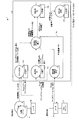
- FIG. 1 is a schematic diagram illustrating a schematic configuration of a detection system including a detection device according to this embodiment.
- FIG. 2 is a diagram for explaining the processing outline of the detection device.
- FIG. 3 is a diagram for explaining the processing of the detection device.
- FIG. 4 is a diagram for explaining the process of the detection device.
- FIG. 5 is a diagram for explaining the process of the detection device.
- FIG. 6 is a diagram for explaining the processing of the detection device.
- FIG. 7 is a flowchart showing a detection processing procedure by the detection device.
- FIG. 8 is a flowchart showing a detection processing procedure by the detection device.
- FIG. 9 is a flowchart showing a detection processing procedure by the detection device.
- FIG. 10 is a diagram illustrating an example of a computer that executes the detection program.
- FIG. 1 is a schematic diagram illustrating a schematic configuration of a detection system including a detection device according to this embodiment.
- the detection system 1 includes a router 3 and a detection device 10.
- the router 3 is realized by, for example, an NP (Network Processor) or an FPGA (Field Programmable Gate Array), and includes a router 3a in an operating environment and a router 3b in a verification environment.
- the router 3a in the operating environment is a transfer device that connects to the operating Web server 2 and transfers packets between the Web server 2 and the user.
- the router 3b in the verification environment is a transfer device that transfers a packet attacked using the known attack tool 4 to the detection device 10.
- the detection device 10 learns an attack in the operating environment and its attack by learning using the L(Layer) 3 to L4 information of the packets acquired from the router 3a in the operating environment and the router 3b in the verification environment by the detection processing described later. And the attack tool 4 used for.
- FIG. 2 is a diagram for explaining a processing outline of the detection apparatus 10.
- the detection device 10 calculates a feature amount using L3 to L4 information such as 5 tuples of an operating environment packet and predetermined field values, and unsupervised ML (Machine Learning, hereinafter referred to as learning). And classify the packet as normal or abnormal.
- L3 to L4 information such as 5 tuples of an operating environment packet and predetermined field values, and unsupervised ML (Machine Learning, hereinafter referred to as learning).
- learning unsupervised ML
- the detection device 10 acquires the L3 to L4 information of the packet attacked by the known attack tool 4 in the verification environment, attaches a label indicating the attack type and tool name of the attack tool 4, and teaches this. Supervised learning is performed as data to learn the labeling.
- the detection device 10 attaches a label indicating the attack type and the tool name to the packets classified as abnormal among the packets in the operating environment.
- the detection device 10 selects a countermeasure according to the attack type of the detected attack and notifies the router 3a of the operating environment of the selected countermeasure. For example, the detection device 10 instructs the router 3a to perform filter setting and sending of RST (Reset) packets.
- the detection device 10 is realized by a general-purpose computer such as a personal computer, and includes an input unit 11, an output unit 12, a communication control unit 13, a storage unit 14, and a control unit 15.
- the input unit 11 is realized by an input device such as a keyboard and a mouse, and inputs various instruction information such as processing start to the control unit 15 in response to an input operation by an operator.
- the output unit 12 is realized by a display device such as a liquid crystal display and a printing device such as a printer.
- the communication control unit 13 is realized by a NIC (Network Interface Card) or the like, and controls communication between the control unit 15 and an external device such as an IoT gateway 2 via a telecommunication line such as a LAN (Local Area Network) or the Internet. To do.
- NIC Network Interface Card
- LAN Local Area Network
- the storage unit 14 is realized by a semiconductor memory device such as a RAM (Random Access Memory) or a flash memory (Flash Memory), or a storage device such as a hard disk or an optical disk.
- the storage unit 14 stores a processing program for operating the detection device 10, data used during the execution of the processing program, or the like in advance, or temporarily for each processing.
- the storage unit 14 stores the L3 to L4 information of the packet acquired from the router 3 in the detection process described later, the classification threshold, the model parameter of the learning result, the coping information 14a, and the like.
- the storage unit 14 may be configured to communicate with the control unit 15 via the communication control unit 13.
- the control unit 15 is realized by a CPU (Central Processing Unit) or the like and executes a processing program stored in the memory. As a result, the control unit 15 functions as the acquisition unit 15a, the feature amount calculation unit 15b, the classification unit 15c, the addition unit 15d, the learning unit 15e, and the coping unit 15f, as illustrated in FIG. Note that these functional units may be implemented individually or in a part of different hardware. For example, the coping unit 15f may be implemented in a device different from other functional units. Moreover, the control unit 15 may be configured to include other functional units.
- a CPU Central Processing Unit
- the acquisition unit 15a acquires the header information of the packet from the router 3. For example, the acquisition unit 15a extracts the L3 to L4 information of the packet passing through the router 3.
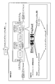
- FIGS. 3 to 6 are diagrams for explaining the process of the detection device 10.
- the acquisition unit 15a loads the protocol stack (Ether, IPv4, TCP, and payload) of the packet passing through the router 3 into the parser included in the detection device 10. Then, the acquisition unit 15a extracts the value of 5tuple and the value of the predetermined header field of all the packets, and loads them into the predetermined table of the storage unit 14.
- the protocol stack Ether, IPv4, TCP, and payload
- the acquisition unit 15a may extract the value of 5tuple of the packet passing through the router 3 and the value of a predetermined header field when the packet is input (ingress) from the router 3. However, the packet may be extracted when the packet is output (egress) to the router 3.
- 5 tuples are a source IP address (src_ip), a destination IP address (dst_ip), a source port number (src_port), a destination port number (dst_port), and a protocol (protocol).
- the predetermined header field is a field of interest of the header.
- the header field key shown in FIG. 3 means a field name or the like that identifies a field of interest in the header. As illustrated in FIG. 3, the header field of interest is not limited to one, but may be plural.
- the characteristic amount calculation unit 15b calculates the characteristic amount of the header information of the packet. Specifically, the feature amount calculation unit 15b calculates the feature amount for each 5 tuples by using the number of packets for each 5 tuples and the distribution of the values of a predetermined header field. Further, the classification unit 15c classifies the packet into either normal or abnormal using the calculated feature amount.
- FIG. 4 illustrates the processing of the feature amount calculation unit 15b and the classification unit 15c.
- the characteristic amount calculation unit 15b calculates the characteristic amount using the header information of the packet acquired by the acquisition unit 15a from the router 3a in the operating environment.
- the feature amount calculation unit 15b counts the number of packets for each 5 tuples and creates a distribution of values for each header field. Further, the feature amount calculation unit 15b calculates a representative value such as an average value, a variance, a maximum value or a mode value of the distribution and a packet per second (pps) for each predetermined time. Then, the feature amount calculation unit 15b uses the representative value of each header field of each 5 tuples and the packet per second to calculate the feature amount for each 5 tuples. This feature amount is represented in, for example, a vector format.
- the feature amount calculation unit 15b clears the packet number counter and the created distribution after calculating the feature amount.
- the classifying unit 15c performs unsupervised learning using the feature amount for each 5 tuples calculated by the feature amount calculating unit 15b, and classifies the score calculated from the feature amount for every 5 tuples as either normal or abnormal. For example, the classification unit 15c stores the classification threshold determined as a result of learning in the storage unit 14 and uses it as the classification threshold in the subsequent processing.
- the classification unit 15c may output the header information of the packet classified as abnormal to the external management device or the like via the output unit 12 or the communication control unit 13 to notify the abnormality.
- the attaching unit 15d attaches a label indicating the tool name of the attack tool to the header information of the packet attacked using the known attack tool 4. Further, the learning unit 15e learns the labeling by using the label and the feature amount calculated for the packet to which the label is assigned as the teacher data.
- FIG. 5 exemplifies the processing of the adding unit 15d, the feature amount calculating unit 15b, and the learning unit 15e.
- the adding unit 15d adds the attack of the attack tool 4 to the header information of the packet attacked using the known attack tool 4 acquired by the acquisition unit 15a from the router 3b in the verification environment. A label indicating the type and tool name is given.
- the label assigned by the assigning unit 15d does not necessarily have to be both the attack type and the tool name, and either one may be used. For example, when the attack type can be uniquely specified from the tool name of the attack tool 4, the assigning unit 15d may assign only the label indicating the tool name.
- the feature amount calculation unit 15b calculates the feature amount using the header information of the packet to which this label is added, as a process at the time of learning. Specifically, the feature quantity calculation unit 15b counts the number of packets, creates a distribution of values for each header field, and calculates a representative value and a packet per second (pps) for each predetermined time. Then, the characteristic amount calculation unit 15b calculates the characteristic amount of the packet to which this label is attached, using the representative value of each header field and the packet per second.
- the learning unit 15e performs supervised learning using the label and the feature amount calculated from the header information of the packet to which the label is attached as teacher data, and learns to attach the label to the header information of the packet. ..
- the learning unit 15e determines the parameters of the model indicating the relationship between the feature amount and the label calculated using the packet header information, and stores the parameters in the storage unit 14.
- FIG. 5 exemplifies a process of calculating the feature amount using the header information of the packet classified as abnormal by the classification unit 15c as the process of the feature amount calculation unit 15b at the time of estimation.
- the feature amount calculation unit 15b counts the number of packets for each 5 tuples, creates a distribution of values for each header field, and represents the distribution representative for each predetermined time, as in the example shown in FIG. Calculate the value and packet per second (pps). Then, the feature amount calculation unit 15b calculates the feature amount for each attack 5 tuple using the representative value of each header field of each attack 5 tuple and the packet per second.
- the example shown in FIG. 5 differs from the example shown in FIG. 4 only in that the 5 tuple of the packet to be processed is an attack 5 tuple.
- the coping unit 15f refers to the coping information 14a of the storage unit 14 with respect to the packet which is classified as abnormal by the classifying unit 15c and is labeled by the learned learning unit 15e, and coping with the attack type corresponding to the label. Choose a law.
- the countermeasure information 14a is information in which the attack type of the attack tool and the countermeasure are associated with each other.
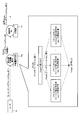
- FIG. 6 exemplifies the processing for the packet in the operating environment.
- the characteristic amount calculating unit 15b calculates the characteristic amount using the header information of the packet acquired by the acquiring unit 15a from the router 3a in the operating environment. Note that in FIG. 6, the processing shown in FIG. 4 and the processing at the time of estimation shown in FIG.
- the classification unit 15c classifies the score calculated from the feature amount for each 5 tuples into normal or abnormal, using the feature amount for every 5 tuples calculated by the feature amount calculation unit 15b.
- the learning unit 15e learned as illustrated in FIG. 5 adds a label indicating the attack type and the tool name of the attack tool 4 to the header information of the packet classified as abnormal.
- the learning unit 15e attaches a label to the header information of the packet classified as abnormal by using, for example, a model to which the parameters stored in the storage unit 14 are applied.
- the countermeasure unit 15f refers to the countermeasure information 14a and selects the countermeasure for the attack type corresponding to the label.
- the countermeasure information 14a is information in which attack types such as “http_get_flooding” and “slow_dos” are associated with countermeasures such as “filter setting” and “RST packet transmission”.
- the coping unit 15f selects “filter setting” as a coping method. Then, the coping unit 15f notifies the router 3a of the selected coping method. As a result, the router 3a in the operating environment can appropriately deal with the detected attack.
- FIG. 7 illustrates a classification processing procedure in the operating environment.
- the flowchart of FIG. 7 starts, for example, at the timing when the user inputs an operation instructing the start.
- the acquisition unit 15a acquires the header information of the packet from the router 3a in the operating environment (step S1). For example, the acquisition unit 15a extracts the L3 to L4 information of the packet passing through the router 3a.
- the characteristic amount calculation unit 15b calculates the characteristic amount of the header information of the packet (step S2). Specifically, the feature amount calculation unit 15b calculates the feature amount for each 5 tuples by using the number of packets for each 5 tuples and the distribution of the values of a predetermined header field.
- the classification unit 15c classifies the packet into either normal or abnormal using the calculated feature amount (step S3). Specifically, the classification unit 15c classifies the score calculated from the feature amount for each 5 tuples calculated by the feature amount calculation unit 15b into either normal or abnormal. For example, the classification unit 15c determines a classification threshold value during learning and uses it as a classification threshold value in subsequent processing.
- the classification unit 15c may output the header information of the packet classified as abnormal to the external management device or the like via the output unit 12 or the communication control unit 13 to notify the abnormality. This completes a series of processes.
- FIG. 8 exemplifies a learning process procedure for labeling.
- the flowchart of FIG. 8 is started, for example, at the timing when the user performs an operation input instructing the start.
- the acquisition unit 15a acquires the header information of the packet attacked using the known attack tool 4 from the router 3b in the verification environment (step S11). For example, the acquisition unit 15a extracts the L3 to L4 information of the packet transferred from the router 3b.
- the adding unit 15d adds a label indicating the tool name of the attack tool 4 to the header information of the attacked packet (step S12).
- the characteristic amount calculation unit 15b calculates the characteristic amount using the header information of the packet to which the label is added. Then, the learning unit 15e learns the labeling by using the label and the feature amount calculated for the labeled packet as the teacher data (step S13). The learning unit 15e determines, for example, a model parameter indicating the relationship between the feature amount and the label calculated using the header information of the packet, and stores the parameter in the storage unit 14. This completes the series of processes.
- FIG. 9 illustrates a processing procedure for a packet in the operating environment.
- the flowchart of FIG. 9 starts, for example, at the timing when the user performs an operation input instructing the start. ..
- the acquisition unit 15a acquires packet header information from the router 3a in the operating environment (step S21). For example, the acquisition unit 15a extracts the L3 to L4 information of the packet passing through the router 3a.
- the characteristic amount calculation unit 15b calculates the characteristic amount of the header information of the packet (step S22). Specifically, the feature amount calculation unit 15b calculates the feature amount for each 5 tuples by using the number of packets for each 5 tuples and the distribution of the values of a predetermined header field.
- the classification unit 15c classifies the packet into either normal or abnormal using the calculated feature amount (step S23). Specifically, the classification unit 15c classifies the score calculated from the feature amount for each 5 tuples calculated by the feature amount calculation unit 15b into either normal or abnormal.
- the learned learning unit 15e attaches a label indicating the attack type of the attack tool 4 and the tool name to the header information of the packet classified as abnormal (step S24).
- the learning unit 15e attaches a label to the header information of the packet classified as abnormal using, for example, a model to which the parameters stored in the storage unit 14 are applied.
- the coping unit 15f refers to the coping information 14a and selects a coping method for the attack type corresponding to the label (step S25). In addition, the coping unit 15f outputs the selected coping method to the router 3a. As a result, the series of processes is completed, and the router 3a in the operating environment can appropriately deal with the detected attack.
- the feature amount calculation unit 15b calculates the feature amount of the header information of the packet. Specifically, the characteristic amount calculation unit 15b calculates the characteristic amount using the number of packets for every 5 tuples and the distribution of the values of a predetermined header field. Further, the classification unit 15c classifies the packet into either normal or abnormal using the calculated feature amount.
- the adding unit 15d adds a label indicating the tool name of the attack tool to the header information of the packet attacked using the known attack tool. Further, the learning unit 15e learns the labeling by using the label and the feature amount calculated for the labeled packet as the teacher data. This makes it possible to detect various attacks and guess the attack tool. Therefore, it becomes possible for the router 3a in the operating environment to take appropriate measures to cut off the attack communication.
- the storage unit 14 also stores the countermeasure information 14a in which the attack type of the attack tool and the countermeasure are associated with each other.
- the coping unit 15f refers to the storage unit 14 for a packet that is classified as abnormal by the classifying unit 15c and is given a label by the learned learning unit 15e, and performs a coping method for an attack type corresponding to the label. select. As a result, the router 3a in the operating environment can easily take appropriate measures.
- the detection device 10 can be implemented by installing a detection program that executes the above-described detection processing as package software or online software in a desired computer.
- the information processing apparatus can be caused to function as the detection apparatus 10.
- the information processing device referred to here includes a desktop or notebook personal computer.
- the information processing device also includes a mobile communication terminal such as a smartphone, a mobile phone, a PHS (Personal Handyphone System), and a slate terminal such as a PDA (Personal Digital Assistant) in its category.
- FIG. 10 is a diagram illustrating an example of a computer that executes a detection program.
- the computer 1000 has, for example, a memory 1010, a CPU 1020, a hard disk drive interface 1030, a disk drive interface 1040, a serial port interface 1050, a video adapter 1060, and a network interface 1070. These units are connected by a bus 1080.
- the memory 1010 includes a ROM (Read Only Memory) 1011 and a RAM 1012.
- the ROM 1011 stores, for example, a boot program such as BIOS (Basic Input Output System).
- BIOS Basic Input Output System
- the hard disk drive interface 1030 is connected to the hard disk drive 1031.
- the disk drive interface 1040 is connected to the disk drive 1041.
- a removable storage medium such as a magnetic disk or an optical disk is inserted into the disk drive 1041.
- a mouse 1051 and a keyboard 1052 are connected to the serial port interface 1050, for example.
- a display 1061 is connected to the video adapter 1060, for example.
- the hard disk drive 1031 stores, for example, an OS 1091, an application program 1092, a program module 1093, and program data 1094. Each information described in the above embodiment is stored in, for example, the hard disk drive 1031 or the memory 1010.
- the detection program is stored in the hard disk drive 1031 as a program module 1093 in which a command executed by the computer 1000 is described, for example.
- the program module 1093 in which each process executed by the detection device 10 described in the above embodiment is described is stored in the hard disk drive 1031.
- data used for information processing by the detection program is stored as program data 1094 in, for example, the hard disk drive 1031.
- the CPU 1020 reads the program module 1093 and the program data 1094 stored in the hard disk drive 1031 into the RAM 1012 as necessary, and executes the above-described procedures.
- the program module 1093 and the program data 1094 related to the detection program are not limited to being stored in the hard disk drive 1031 and may be stored in a removable storage medium and read by the CPU 1020 via the disk drive 1041 or the like. May be done. Alternatively, the program module 1093 and the program data 1094 related to the detection program are stored in another computer connected via a network such as LAN or WAN (Wide Area Network) and read by the CPU 1020 via the network interface 1070. May be.
- LAN or WAN Wide Area Network
Landscapes
- Engineering & Computer Science (AREA)
- Computer Security & Cryptography (AREA)
- Computer Hardware Design (AREA)
- Computing Systems (AREA)
- General Engineering & Computer Science (AREA)
- Computer Networks & Wireless Communication (AREA)
- Signal Processing (AREA)
- Data Exchanges In Wide-Area Networks (AREA)
Abstract
特徴量算出部(15b)が、パケットのヘッダ情報の特徴量を算出する。分類部(15c)が、算出された特徴量を用いてパケットを正常または異常のいずれかに分類する。付与部(15d)が、既知の攻撃ツールを用いて攻撃されたパケットのヘッダ情報に、該攻撃ツールのツール名を示すラベルを付与する。学習部(15e)が、ラベルと、ラベルが付与されたパケットについて算出された特徴量とを教師データとして用いて、ラベルの付与を学習する。
Description
本発明は、検知装置および検知方法に関する。
近年、HTTP Flood、Slow DoS(Denial Of Service)等と呼ばれる、単位時間あたりのパケット数が少ない低レート攻撃の存在が知られている。また、このような低レート攻撃に対する対策技術が知られている。例えば、xFlowを用いて検知した攻撃通信をセキュリティ装置に引き込んで対策を行う技術が知られている(非特許文献1参照)。また、WAF(Web Application Firewall)等のセキュリティ装置をインライン接続して攻撃通信を検知して対策する技術が知られている(非特許文献2参照)。また、Webサーバ上で攻撃を検知して対策を行う技術が知られている(非特許文献3,4参照)。また、特定の種別の攻撃を検知する技術が知られている(特許文献1,2参照)。
西塚要、"ISPにおけるDoS/DDoS攻撃の検知・対策技術"、[online]、2013年、NTTコミュニケーションズ株式会社、[2019年1月15日検索]、インターネット<URL:https://www.nic.ad.jp/ja/materials/iw/2013/proceedings/s2/s2-nishizuka.pdf>
"Barracuda Web Application Firewall"、[online]、ITmedia Inc.、[2019年1月15日検索]、インターネット<URL:http://www.keyman.or.jp/nwsec/waf/product/30973>
"Are you ready for slow reading?"、[online]、Qualys Inc.、[2019年1月15日検索]、インターネット<URL:https://blog.qualys.com/securitylabs/2012/01/05/slow-read>
"ModSecurity 3.0"、[online]、Trustwave、[2019年1月15日検索]、インターネット<URL:https://www.modsecurity.org/>
しかしながら、従来の技術では、低レート攻撃の検知が困難な場合がある。例えば、非特許文献1に記載の技術は、通信のサンプリングを前提とする技術であるため、低レート攻撃に関する情報を取得できず、セキュリティ装置への引き込みのトリガがないという問題がある。また、非特許文献2に記載の技術は、セキュリティ装置のGbps単価が高く、通常通信を検知の対象とするとコストが高くなるという問題がある。また、非特許文献3,4に記載の技術では、通常通信のQoSに影響があったりWebサーバへの負荷がかかったりするという問題がある。また、特許文献1,2に記載の技術では、検知できる攻撃の種別が限定され、攻撃に使われた攻撃ツールを判別できないという問題がある。
本発明は、上記に鑑みてなされたものであって、低レート攻撃を容易に検知して対処可能とすること目的とする。
上述した課題を解決し、目的を達成するために、本発明に係る検知装置は、パケットのヘッダ情報の特徴量を算出する特徴量算出部と、算出された前記特徴量を用いて前記パケットを正常または異常のいずれかに分類する分類部と、を備えることを特徴とする。
本発明によれば、低レート攻撃を容易に検知して対処することが可能となる。
以下、図面を参照して、本発明の一実施形態を詳細に説明する。なお、この実施形態により本発明が限定されるものではない。また、図面の記載において、同一部分には同一の符号を付して示している。
[検知システムの構成]
図1は、本実施形態に係る検知装置を含む検知システムの概略構成を例示する模式図である。図1に例示するように、検知システム1は、ルータ3と検知装置10とを含んで構成される。ルータ3は、例えば、NP(Network Processor)やFPGA(Field Programmable Gate Array)等で実現され、運用環境のルータ3aと検証環境のルータ3bとを含む。運用環境のルータ3aは、運用中のWebサーバ2に接続し、Webサーバ2とユーザとの間でパケットを転送する転送装置である。検証環境のルータ3bは、既知の攻撃ツール4を用いて攻撃されたパケットを検知装置10に転送する転送装置である。
図1は、本実施形態に係る検知装置を含む検知システムの概略構成を例示する模式図である。図1に例示するように、検知システム1は、ルータ3と検知装置10とを含んで構成される。ルータ3は、例えば、NP(Network Processor)やFPGA(Field Programmable Gate Array)等で実現され、運用環境のルータ3aと検証環境のルータ3bとを含む。運用環境のルータ3aは、運用中のWebサーバ2に接続し、Webサーバ2とユーザとの間でパケットを転送する転送装置である。検証環境のルータ3bは、既知の攻撃ツール4を用いて攻撃されたパケットを検知装置10に転送する転送装置である。
検知装置10は、後述する検知処理により、運用環境のルータ3aおよび検証環境のルータ3bから取得したパケットのL(Layer)3~L4情報を用いた学習により、運用環境での攻撃と、その攻撃に使用された攻撃ツール4とを検知する。
ここで、図2は、検知装置10の処理概要を説明するための図である。詳細は後述するが、検知装置10は、運用環境のパケットの5tupleと所定のフィールド値等のL3~L4情報を用いて特徴量を算出し、教師無ML(Machine Learning、以下、学習と記す)を行って、パケットを正常または異常に分類する。
また、検知装置10は、検証環境の既知の攻撃ツール4で攻撃されたパケットのL3~L4情報を取得して、攻撃ツール4の攻撃種別とツール名とを示すラベルを付与し、これを教師データとして教師有学習を行って、ラベルの付与を学習する。
これにより、検知装置10は、運用環境のパケットのうち、異常として分類したパケットに攻撃種別とツール名とを示すラベルを付与する。また、検知装置10は、検知した攻撃の攻撃種別に応じた対処法を選択し、運用環境のルータ3aに通知する。例えば、検知装置10は、ルータ3aに対し、フィルタ設定やRST(Reset)パケットの送付を指示したりする。
[検知装置の構成]
図1の説明に戻る。検知装置10は、パソコン等の汎用コンピュータで実現され、入力部11、出力部12、通信制御部13、記憶部14、および制御部15を備える。
図1の説明に戻る。検知装置10は、パソコン等の汎用コンピュータで実現され、入力部11、出力部12、通信制御部13、記憶部14、および制御部15を備える。
入力部11は、キーボードやマウス等の入力デバイスによって実現され、操作者による入力操作に対応して、制御部15に対して処理開始などの各種指示情報を入力する。出力部12は、液晶ディスプレイなどの表示装置、プリンター等の印刷装置等によって実現される。
通信制御部13は、NIC(Network Interface Card)等で実現され、LAN(Local Area Network)やインターネット等の電気通信回線を介したIoTゲートウェイ2等の外部の装置と制御部15との通信を制御する。
記憶部14は、RAM(Random Access Memory)、フラッシュメモリ(Flash Memory)等の半導体メモリ素子、または、ハードディスク、光ディスク等の記憶装置によって実現される。記憶部14には、検知装置10を動作させる処理プログラムや、処理プログラムの実行中に使用されるデータなどが予め記憶され、あるいは処理の都度一時的に記憶される。例えば、記憶部14には、後述する検知処理においてルータ3から取得したパケットのL3~L4情報や、分類の閾値、学習結果のモデルのパラメータ、および対処情報14a等が記憶される。なお、記憶部14は、通信制御部13を介して制御部15と通信する構成でもよい。
制御部15は、CPU(Central Processing Unit)等によって実現され、メモリに記憶された処理プログラムを実行する。これにより、制御部15は、図1に例示するように、取得部15a、特徴量算出部15b、分類部15c、付与部15d、学習部15eおよび対処部15fとして機能する。なお、これらの機能部は、それぞれ、あるいは一部が異なるハードウェアに実装されてもよい。例えば、対処部15fは、他の機能部とは異なる装置に実装されてもよい。また、制御部15は、その他の機能部が含まれて構成されてもよい。
取得部15aは、ルータ3からパケットのヘッダ情報を取得する。例えば、取得部15aは、ルータ3を経由するパケットのL3~L4情報を抽出する。
ここで、図3~図6は、検知装置10の処理を説明するための図である。まず、図3には、取得部15aの処理が例示されている。図3に例示するように、取得部15aは、ルータ3を経由するパケットのプロトコルスタック(Ether、IPv4、TCPおよびペイロード)を検知装置10に内蔵するパーサにロードする。そして、取得部15aは、全パケットの5tupleの値と所定のヘッダフィールドの値とを抽出し、記憶部14の所定のテーブルにロードする。
なお、図3に例示するように、取得部15aは、ルータ3を経由するパケットの5tupleの値と所定のヘッダフィールドの値とを、ルータ3からのパケット入力(ingress)時に抽出してもよいし、ルータ3へのパケット出力(egress)時に抽出してもよい。
ここで、5tupleとは、送信元IPアドレス(src_ip)、送信先IPアドレス(dst_ip)、送信元ポート番号(src_port)、送信先ポート番号(dst_port)、プロトコル(protocol)である。また、所定のヘッダフィールドとは、ヘッダの着目するフィールドのことである。図3に示すヘッダフィールドkeyとは、ヘッダの着目するフィールドを特定するフィールド名等を意味する。図3に例示するように、着目するヘッダフィールドは1つに限定されず、複数であってもよい。
特徴量算出部15bは、パケットのヘッダ情報の特徴量を算出する。具体的には、特徴量算出部15bは、5tupleごとのパケット数と所定のヘッダフィールドの値の分布とを用いて、5tupleごとの特徴量を算出する。また、分類部15cは、算出された特徴量を用いてパケットを正常または異常のいずれかに分類する。
ここで、図4には、特徴量算出部15bおよび分類部15cの処理が例示されている。図4に例示するように、まず、特徴量算出部15bは、運用環境のルータ3aから取得部15aが取得したパケットのヘッダ情報を用いて特徴量を算出する。
具体的には、特徴量算出部15bは、5tupleごとに、パケット数をカウントし、ヘッダフィールドごとに値の分布を作成する。また、特徴量算出部15bは、所定時間ごとに、分布の平均値、分散、最大値あるいは最頻値等の代表値とパケット毎秒(pps)とを算出する。そして、特徴量算出部15bは、各5tupleの各ヘッダフィールドの代表値とパケット毎秒とを用いて、5tupleごとの特徴量を算出する。この特徴量は、例えばベクトル形式で表される。
なお、特徴量算出部15bは、特徴量を算出した後に、パケット数のカウンタと作成した分布とをクリアする。
分類部15cは、特徴量算出部15bが算出した5tupleごとの特徴量を用いて教師無学習を行って、5tupleごとの特徴量から算出されるスコアを正常または異常のいずれかに分類する。例えば、分類部15cは、学習の結果、決定された分類の閾値を記憶部14に記憶させ、以後の処理における分類の閾値として用いる。
図4には、異常と分類された場合が「攻撃5tuple」として例示されている。分類部15cは、異常と分類したパケットのヘッダ情報を、出力部12あるいは通信制御部13を介して外部の管理装置等に出力して、異常を通知してもよい。
図1の説明に戻る。付与部15dは、既知の攻撃ツール4を用いて攻撃されたパケットのヘッダ情報に、該攻撃ツールのツール名を示すラベルを付与する。また、学習部15eは、ラベルと、このラベルが付与されたパケットについて算出された特徴量とを教師データとして用いて、ラベルの付与を学習する。
ここで、図5には、付与部15d、特徴量算出部15bおよび学習部15eの処理が例示されている。図5に例示するように、まず、付与部15dは、検証環境のルータ3bから取得部15aが取得した、既知の攻撃ツール4を用いて攻撃されたパケットのヘッダ情報に、攻撃ツール4の攻撃種別とツール名とを示すラベルを付与する。
なお、付与部15dが付与するラベルは、必ずしも攻撃種別、ツール名の双方でなくてもよく、いずれか一方でもよい。例えば、攻撃ツール4のツール名から攻撃種別を一意に特定できる場合には、付与部15dは、ツール名を示すラベルのみを付与してもよい。
また、特徴量算出部15bは、学習時の処理として、このラベルが付与されたパケットのヘッダ情報を用いて特徴量を算出する。具体的には、特徴量算出部15bは、パケット数をカウントし、ヘッダフィールドごとに値の分布を作成し、所定時間ごとに、代表値とパケット毎秒(pps)とを算出する。そして、特徴量算出部15bは、各ヘッダフィールドの代表値とパケット毎秒とを用いて、このラベルが付与されたパケットの特徴量を算出する。
そして、学習部15eは、ラベルと、このラベルが付与されたパケットのヘッダ情報から算出された特徴量とを教師データとして教師有学習を行って、パケットのヘッダ情報へのラベルの付与を学習する。例えば、学習部15eは、パケットのヘッダ情報を用いて算出される特徴量とラベルとの関係を示すモデルのパラメータを決定し、記憶部14に記憶させる。
なお、図5には、特徴量算出部15bの推測時の処理として、分類部15cによって異常と分類されたパケットのヘッダ情報を用いて特徴量を算出する処理が例示されている。この場合に、特徴量算出部15bは、図4に示した例と同様に、5tupleごとに、パケット数をカウントし、ヘッダフィールドごとに値の分布を作成し、所定時間ごとに、分布の代表値とパケット毎秒(pps)とを算出する。そして、特徴量算出部15bは、各攻撃5tupleの各ヘッダフィールドの代表値とパケット毎秒とを用いて、攻撃5tupleごとの特徴量を算出する。なお、図5に示す例は、図4に示した例とは、処理対象のパケットの5tupleが攻撃5tupleであることのみが異なっている。
図1の説明に戻る。対処部15fは、分類部15cによって異常と分類され、学習された学習部15eによってラベルが付与されたパケットに対し、記憶部14の対処情報14aを参照し、該ラベルに対応する攻撃種別の対処法を選択する。対処情報14aは、攻撃ツールの攻撃種別と対処法とを対応付けした情報である。
ここで、図6には、運用環境のパケットに対する処理が例示されている。運用環境において、まず、特徴量算出部15bは、取得部15aが運用環境のルータ3aから取得したパケットのヘッダ情報を用いて特徴量を算出する。なお、図6には、図4に示した処理と図5に示した推測時の処理とが区別されずに同一の処理として例示されている。
次に、分類部15cが、特徴量算出部15bが算出した5tupleごとの特徴量を用いて、5tupleごとの特徴量から算出されるスコアを正常または異常のいずれかに分類する。また、異常と分類されたパケットのヘッダ情報に対し、図5に例示したようにして学習された学習部15eが、攻撃ツール4の攻撃種別とツール名とを示すラベルを付与する。この場合に、学習部15eは、例えば、記憶部14に記憶されているパラメータを適用したモデルを用いて、異常と分類されたパケットのヘッダ情報にラベルを付与する。
そして、攻撃ツール4の攻撃種別とツール名とを示すラベルが付与されたパケットについて、対処部15fが、対処情報14aを参照し、ラベルに対応する攻撃種別の対処法を選択する。図6に例示するように、対処情報14aは、「http_get_flooding」、「slow_dos」等の攻撃種別と、「フィルタ設定」、「RSTパケット送付」等の対処法とが対応付けされた情報である。
対処部15fは、例えば、ラベルが示す攻撃ツール4の攻撃種別が「http_get_flooding」である場合に、対処法として「フィルタ設定」を選択する。そして、対処部15fは、選択した対処法をルータ3aに通知する。これにより、運用環境のルータ3aは、検知された攻撃に対する適切な対処を実施することが可能となる。
[検知処理]
図7~図9は、検知装置10による検知処理手順を示すフローチャートである。まず、図7には、運用環境における分類処理手順が例示されている。図7のフローチャートは、例えば、ユーザが開始を指示する操作入力を行ったタイミングで開始される。
図7~図9は、検知装置10による検知処理手順を示すフローチャートである。まず、図7には、運用環境における分類処理手順が例示されている。図7のフローチャートは、例えば、ユーザが開始を指示する操作入力を行ったタイミングで開始される。
まず、取得部15aが、運用環境のルータ3aからパケットのヘッダ情報を取得する(ステップS1)。例えば、取得部15aは、ルータ3aを経由するパケットのL3~L4情報を抽出する。
次に、特徴量算出部15bが、パケットのヘッダ情報の特徴量を算出する(ステップS2)。具体的には、特徴量算出部15bは、5tupleごとのパケット数と所定のヘッダフィールドの値の分布とを用いて、5tupleごとの特徴量を算出する。
次に、分類部15cが、算出された特徴量を用いてパケットを正常または異常のいずれかに分類する(ステップS3)。具体的には、分類部15cは、特徴量算出部15bが算出した5tupleごとの特徴量から算出されるスコアを正常または異常のいずれかに分類する。分類部15cは、例えば、学習の際に分類の閾値を決定し、以後の処理における分類の閾値として用いる。
分類部15cは、異常と分類したパケットのヘッダ情報を、出力部12あるいは通信制御部13を介して外部の管理装置等に出力して異常を通知してもよい。これにより一連の処理が終了する。
次に、図8には、ラベル付与の学習処理手順が例示されている。図8のフローチャートは、例えば、ユーザが開始を指示する操作入力を行ったタイミングで開始される。
まず、取得部15aが、検証環境のルータ3bから既知の攻撃ツール4を用いて攻撃されたパケットのヘッダ情報を取得する(ステップS11)。例えば、取得部15aは、ルータ3bから転送されたパケットのL3~L4情報を抽出する。
次に、付与部15dが、攻撃されたパケットのヘッダ情報に、攻撃ツール4のツール名を示すラベルを付与する(ステップS12)。
また、特徴量算出部15bが、ラベルが付与されたパケットのヘッダ情報を用いて特徴量を算出する。そして、学習部15eが、ラベルとラベルが付与されたパケットについて算出された特徴量とを教師データとして用いて、ラベルの付与を学習する(ステップS13)。学習部15eは、例えば、パケットのヘッダ情報を用いて算出される特徴量とラベルとの関係を示すモデルのパラメータを決定し、記憶部14に記憶させる。これにより、一連の処理が終了する。
次に、図9には、運用環境のパケットに対する処理手順が例示されている。図9のフローチャートは、例えば、ユーザが開始を指示する操作入力を行ったタイミングで開始される。
まず、取得部15aが、運用環境のルータ3aからパケットのヘッダ情報を取得する(ステップS21)。例えば、取得部15aは、ルータ3aを経由するパケットのL3~L4情報を抽出する。
次に、特徴量算出部15bが、パケットのヘッダ情報の特徴量を算出する(ステップS22)。具体的には、特徴量算出部15bは、5tupleごとのパケット数と所定のヘッダフィールドの値の分布とを用いて、5tupleごとの特徴量を算出する。
次に、分類部15cが、算出された特徴量を用いてパケットを正常または異常のいずれかに分類する(ステップS23)。具体的には、分類部15cは、特徴量算出部15bが算出した5tupleごとの特徴量から算出されるスコアを正常または異常のいずれかに分類する。
次に、学習された学習部15eが、異常と分類されたパケットのヘッダ情報に対し、攻撃ツール4の攻撃種別とツール名とを示すラベルを付与する(ステップS24)。この場合に、学習部15eは、例えば、記憶部14に記憶したパラメータを適用したモデルを用いて、異常と分類されたパケットのヘッダ情報にラベルを付与する。
そして、対処部15fが、対処情報14aを参照し、ラベルに対応する攻撃種別の対処法を選択する(ステップS25)。また、対処部15fは、選択した対処法をルータ3aに出力する。これにより、一連の処理が終了し、運用環境のルータ3aは、検知された攻撃に対する適切な対処を実施することが可能となる。
以上、説明したように、本実施形態の検知装置10において、特徴量算出部15bが、パケットのヘッダ情報の特徴量を算出する。具体的には、特徴量算出部15bは、5tupleごとのパケット数と所定のヘッダフィールドの値の分布とを用いて特徴量を算出する。また、分類部15cが、算出された特徴量を用いてパケットを正常または異常のいずれかに分類する。
これにより、パケットのサンプリングもWebサーバ2側で処理も要することなく、容易かつ安価に低レート攻撃を検知することが可能となる。このように、検知装置10によれば、低レート攻撃を容易に検知して対処することが可能となる。
また、付与部15dが、既知の攻撃ツールを用いて攻撃されたパケットのヘッダ情報に、該攻撃ツールのツール名を示すラベルを付与する。また、学習部15eが、ラベルと、ラベルが付与されたパケットについて算出された特徴量とを教師データとして用いて、ラベルの付与を学習する。これにより、多様な攻撃を検知して、攻撃ツールを推測することが可能となる。したがって、運用環境のルータ3aが適切な対処を行って攻撃通信を遮断することが可能となる。
また、記憶部14が、攻撃ツールの攻撃種別と対処法とを対応付けした対処情報14aを記憶する。また、対処部15fが、分類部15cによって異常と分類され、学習された学習部15eによってラベルが付与されたパケットに対し、記憶部14を参照し、該ラベルに対応する攻撃種別の対処法を選択する。これにより、運用環境のルータ3aが容易に適切な対処を実行することが可能となる。
[プログラム]
上記実施形態に係る検知装置10が実行する処理をコンピュータが実行可能な言語で記述したプログラムを検知することもできる。一実施形態として、検知装置10は、パッケージソフトウェアやオンラインソフトウェアとして上記の検知処理を実行する検知プログラムを所望のコンピュータにインストールさせることによって実装できる。例えば、上記の検知プログラムを情報処理装置に実行させることにより、情報処理装置を検知装置10として機能させることができる。ここで言う情報処理装置には、デスクトップ型またはノート型のパーソナルコンピュータが含まれる。また、その他にも、情報処理装置にはスマートフォン、携帯電話機やPHS(Personal Handyphone System)などの移動体通信端末、さらには、PDA(Personal Digital Assistant)などのスレート端末などがその範疇に含まれる。また、検知装置10の機能を、クラウドサーバに実装してもよい。
上記実施形態に係る検知装置10が実行する処理をコンピュータが実行可能な言語で記述したプログラムを検知することもできる。一実施形態として、検知装置10は、パッケージソフトウェアやオンラインソフトウェアとして上記の検知処理を実行する検知プログラムを所望のコンピュータにインストールさせることによって実装できる。例えば、上記の検知プログラムを情報処理装置に実行させることにより、情報処理装置を検知装置10として機能させることができる。ここで言う情報処理装置には、デスクトップ型またはノート型のパーソナルコンピュータが含まれる。また、その他にも、情報処理装置にはスマートフォン、携帯電話機やPHS(Personal Handyphone System)などの移動体通信端末、さらには、PDA(Personal Digital Assistant)などのスレート端末などがその範疇に含まれる。また、検知装置10の機能を、クラウドサーバに実装してもよい。
図10は、検知プログラムを実行するコンピュータの一例を示す図である。コンピュータ1000は、例えば、メモリ1010と、CPU1020と、ハードディスクドライブインタフェース1030と、ディスクドライブインタフェース1040と、シリアルポートインタフェース1050と、ビデオアダプタ1060と、ネットワークインタフェース1070とを有する。これらの各部は、バス1080によって接続される。
メモリ1010は、ROM(Read Only Memory)1011およびRAM1012を含む。ROM1011は、例えば、BIOS(Basic Input Output System)等のブートプログラムを記憶する。ハードディスクドライブインタフェース1030は、ハードディスクドライブ1031に接続される。ディスクドライブインタフェース1040は、ディスクドライブ1041に接続される。ディスクドライブ1041には、例えば、磁気ディスクや光ディスク等の着脱可能な記憶媒体が挿入される。シリアルポートインタフェース1050には、例えば、マウス1051およびキーボード1052が接続される。ビデオアダプタ1060には、例えば、ディスプレイ1061が接続される。
ここで、ハードディスクドライブ1031は、例えば、OS1091、アプリケーションプログラム1092、プログラムモジュール1093およびプログラムデータ1094を記憶する。上記実施形態で説明した各情報は、例えばハードディスクドライブ1031やメモリ1010に記憶される。
また、検知プログラムは、例えば、コンピュータ1000によって実行される指令が記述されたプログラムモジュール1093として、ハードディスクドライブ1031に記憶される。具体的には、上記実施形態で説明した検知装置10が実行する各処理が記述されたプログラムモジュール1093が、ハードディスクドライブ1031に記憶される。
また、検知プログラムによる情報処理に用いられるデータは、プログラムデータ1094として、例えば、ハードディスクドライブ1031に記憶される。そして、CPU1020が、ハードディスクドライブ1031に記憶されたプログラムモジュール1093やプログラムデータ1094を必要に応じてRAM1012に読み出して、上述した各手順を実行する。
なお、検知プログラムに係るプログラムモジュール1093やプログラムデータ1094は、ハードディスクドライブ1031に記憶される場合に限られず、例えば、着脱可能な記憶媒体に記憶されて、ディスクドライブ1041等を介してCPU1020によって読み出されてもよい。あるいは、検知プログラムに係るプログラムモジュール1093やプログラムデータ1094は、LANやWAN(Wide Area Network)等のネットワークを介して接続された他のコンピュータに記憶され、ネットワークインタフェース1070を介してCPU1020によって読み出されてもよい。
以上、本発明者によってなされた発明を適用した実施形態について説明したが、本実施形態による本発明の開示の一部をなす記述および図面により本発明は限定されることはない。すなわち、本実施形態に基づいて当業者等によりなされる他の実施形態、実施例および運用技術等は全て本発明の範疇に含まれる。
1 検知システム
2 Webサーバ
3、3a、3b ルータ
10 検知装置
11 入力部
12 出力部
13 通信制御部
14 記憶部
14a 対処情報
15 制御部
15a 取得部
15b 特徴量算出部
15c 分類部
15d 付与部
15e 学習部
15f 対処部
2 Webサーバ
3、3a、3b ルータ
10 検知装置
11 入力部
12 出力部
13 通信制御部
14 記憶部
14a 対処情報
15 制御部
15a 取得部
15b 特徴量算出部
15c 分類部
15d 付与部
15e 学習部
15f 対処部
Claims (5)
- パケットのヘッダ情報の特徴量を算出する特徴量算出部と、
算出された前記特徴量を用いて前記パケットを正常または異常のいずれかに分類する分類部と、
を備えることを特徴とする検知装置。 - 前記特徴量算出部は、5tupleごとのパケット数と所定のヘッダフィールドの値の分布とを用いて特徴量を算出することを特徴とする請求項1に記載の検知装置。
- 既知の攻撃ツールを用いて攻撃されたパケットのヘッダ情報に、該攻撃ツールのツール名を示すラベルを付与する付与部と、
前記ラベルと、該ラベルが付与されたパケットについて算出された前記特徴量とを教師データとして用いて、前記ラベルの付与を学習する学習部と、
をさらに備えることを特徴とする請求項1に記載の検知装置。 - 前記攻撃ツールの攻撃種別と対処法とを対応付けした対処情報を記憶する記憶部と、
前記分類部によって異常と分類され、学習された前記学習部によって前記ラベルが付与されたパケットに対し、前記記憶部を参照し、該ラベルに対応する攻撃種別の対処法を選択する対処部と、
をさらに備えることを特徴とする請求項3に記載の検知装置。 - 検知装置で実行される検知方法であって、
パケットのヘッダ情報の特徴量を算出する特徴量算出工程と、
算出された前記特徴量を用いて前記パケットを正常または異常のいずれかに分類する分類工程と、
を含んだことを特徴とする検知方法。
Priority Applications (1)
| Application Number | Priority Date | Filing Date | Title |
|---|---|---|---|
| US17/431,863 US11902310B2 (en) | 2019-02-19 | 2020-02-04 | Detection device and detection method |
Applications Claiming Priority (2)
| Application Number | Priority Date | Filing Date | Title |
|---|---|---|---|
| JP2019027505A JP2020136888A (ja) | 2019-02-19 | 2019-02-19 | 検知装置および検知方法 |
| JP2019-027505 | 2019-02-19 |
Publications (1)
| Publication Number | Publication Date |
|---|---|
| WO2020170802A1 true WO2020170802A1 (ja) | 2020-08-27 |
Family
ID=72144699
Family Applications (1)
| Application Number | Title | Priority Date | Filing Date |
|---|---|---|---|
| PCT/JP2020/004102 Ceased WO2020170802A1 (ja) | 2019-02-19 | 2020-02-04 | 検知装置および検知方法 |
Country Status (3)
| Country | Link |
|---|---|
| US (1) | US11902310B2 (ja) |
| JP (1) | JP2020136888A (ja) |
| WO (1) | WO2020170802A1 (ja) |
Families Citing this family (2)
| Publication number | Priority date | Publication date | Assignee | Title |
|---|---|---|---|---|
| US12088610B2 (en) * | 2021-10-27 | 2024-09-10 | Hewlett Packard Enterprise Development Lp | Platform for privacy preserving decentralized learning and network event monitoring |
| JP7747205B2 (ja) * | 2022-06-14 | 2025-10-01 | Ntt株式会社 | データ生成装置、データ生成方法、プログラム、および機械学習システム |
Citations (4)
| Publication number | Priority date | Publication date | Assignee | Title |
|---|---|---|---|---|
| JP2008306706A (ja) * | 2007-04-23 | 2008-12-18 | Mitsubishi Electric Information Technology Centre Europa Bv | シグナリングフローの異常を検知する方法及び装置 |
| WO2016002915A1 (ja) * | 2014-07-04 | 2016-01-07 | 日本電信電話株式会社 | 攻撃検出装置、攻撃検出方法、および攻撃検出プログラム |
| JP2017147558A (ja) * | 2016-02-16 | 2017-08-24 | 日本電信電話株式会社 | 攻撃検知装置、攻撃検知システムおよび攻撃検知方法 |
| US20180152475A1 (en) * | 2016-11-30 | 2018-05-31 | Foundation Of Soongsil University-Industry Cooperation | Ddos attack detection system based on svm-som combination and method thereof |
Family Cites Families (3)
| Publication number | Priority date | Publication date | Assignee | Title |
|---|---|---|---|---|
| JP6502902B2 (ja) | 2016-08-12 | 2019-04-17 | 日本電信電話株式会社 | 攻撃検知装置、攻撃検知システムおよび攻撃検知方法 |
| JP7003864B2 (ja) * | 2018-07-24 | 2022-02-10 | 日本電信電話株式会社 | 振分装置、通信システムおよび振分方法 |
| JP7396454B2 (ja) * | 2020-02-27 | 2023-12-12 | 日本電信電話株式会社 | 付与装置、付与方法及び付与プログラム |
-
2019
- 2019-02-19 JP JP2019027505A patent/JP2020136888A/ja active Pending
-
2020
- 2020-02-04 WO PCT/JP2020/004102 patent/WO2020170802A1/ja not_active Ceased
- 2020-02-04 US US17/431,863 patent/US11902310B2/en active Active
Patent Citations (4)
| Publication number | Priority date | Publication date | Assignee | Title |
|---|---|---|---|---|
| JP2008306706A (ja) * | 2007-04-23 | 2008-12-18 | Mitsubishi Electric Information Technology Centre Europa Bv | シグナリングフローの異常を検知する方法及び装置 |
| WO2016002915A1 (ja) * | 2014-07-04 | 2016-01-07 | 日本電信電話株式会社 | 攻撃検出装置、攻撃検出方法、および攻撃検出プログラム |
| JP2017147558A (ja) * | 2016-02-16 | 2017-08-24 | 日本電信電話株式会社 | 攻撃検知装置、攻撃検知システムおよび攻撃検知方法 |
| US20180152475A1 (en) * | 2016-11-30 | 2018-05-31 | Foundation Of Soongsil University-Industry Cooperation | Ddos attack detection system based on svm-som combination and method thereof |
Non-Patent Citations (1)
| Title |
|---|
| KAZATO, YUTA: "A study of Gini importance-based header feature selection methods for cyber attack detection", IEICE TECHNICAL REPORT, vol. 117, no. 353, 7 December 2017 (2017-12-07), pages 91 - 96 * |
Also Published As
| Publication number | Publication date |
|---|---|
| US20210385241A1 (en) | 2021-12-09 |
| JP2020136888A (ja) | 2020-08-31 |
| US11902310B2 (en) | 2024-02-13 |
Similar Documents
| Publication | Publication Date | Title |
|---|---|---|
| US11611579B2 (en) | Identifying and using DNS contextual flows | |
| EP3229407B1 (en) | Application signature generation and distribution | |
| US7974286B2 (en) | Reduced redundant security screening | |
| CN103607399A (zh) | 基于暗网的专用ip网络安全监测系统及方法 | |
| JP6691268B2 (ja) | 監視装置、監視方法および監視プログラム | |
| TW201505411A (zh) | 用於規則式安全防護設備之規則解譯方法及設備 | |
| White et al. | Unsupervised one-class learning for anomaly detection on home IoT network devices | |
| WO2020170802A1 (ja) | 検知装置および検知方法 | |
| JP2018026747A (ja) | 攻撃検知装置、攻撃検知システムおよび攻撃検知方法 | |
| JP6708575B2 (ja) | 分類装置、分類方法および分類プログラム | |
| US12301597B1 (en) | Network edge digital twin for IoT attack detection | |
| JP6272258B2 (ja) | 最適化装置、最適化方法および最適化プログラム | |
| JP7215571B2 (ja) | 検知装置、検知方法および検知プログラム | |
| CN115190077A (zh) | 控制方法、装置及计算设备 | |
| US10791092B2 (en) | Firewall rules with expression matching | |
| WO2025027768A1 (ja) | 監視システム | |
| CN115086068A (zh) | 一种网络入侵检测方法和装置 | |
| US20250150488A1 (en) | Identifying network-based attacks on physical operational technology (ot) devices with decoy ot devices | |
| JP4777366B2 (ja) | ワーム対策プログラム、ワーム対策装置、ワーム対策方法 | |
| WO2025041343A1 (ja) | 抽出装置 | |
| WO2020261582A1 (ja) | 検知装置、検知方法および検知プログラム | |
| US20260039569A1 (en) | Extracting device, extracting method and extracting program | |
| US20250211617A1 (en) | Methods for capturing reconnaissance traffic | |
| JP7014125B2 (ja) | 検知装置、検知方法および検知プログラム | |
| JP2016170651A (ja) | 不正アクセス検出方法、装置、及びプログラム |
Legal Events
| Date | Code | Title | Description |
|---|---|---|---|
| 121 | Ep: the epo has been informed by wipo that ep was designated in this application |
Ref document number: 20759310 Country of ref document: EP Kind code of ref document: A1 |
|
| NENP | Non-entry into the national phase |
Ref country code: DE |
|
| 122 | Ep: pct application non-entry in european phase |
Ref document number: 20759310 Country of ref document: EP Kind code of ref document: A1 |