WO2020170716A1 - イオン注入装置及びイオンの選別方法 - Google Patents
イオン注入装置及びイオンの選別方法 Download PDFInfo
- Publication number
- WO2020170716A1 WO2020170716A1 PCT/JP2020/002673 JP2020002673W WO2020170716A1 WO 2020170716 A1 WO2020170716 A1 WO 2020170716A1 JP 2020002673 W JP2020002673 W JP 2020002673W WO 2020170716 A1 WO2020170716 A1 WO 2020170716A1
- Authority
- WO
- WIPO (PCT)
- Prior art keywords
- ion
- ions
- ion beam
- interaction
- electrode
- Prior art date
- Legal status (The legal status is an assumption and is not a legal conclusion. Google has not performed a legal analysis and makes no representation as to the accuracy of the status listed.)
- Ceased
Links
Images






Classifications
-
- H—ELECTRICITY
- H01—ELECTRIC ELEMENTS
- H01J—ELECTRIC DISCHARGE TUBES OR DISCHARGE LAMPS
- H01J37/00—Discharge tubes with provision for introducing objects or material to be exposed to the discharge, e.g. for the purpose of examination or processing thereof
- H01J37/02—Details
- H01J37/04—Arrangements of electrodes and associated parts for generating or controlling the discharge, e.g. electron-optical arrangement or ion-optical arrangement
- H01J37/08—Ion sources; Ion guns
-
- H—ELECTRICITY
- H01—ELECTRIC ELEMENTS
- H01J—ELECTRIC DISCHARGE TUBES OR DISCHARGE LAMPS
- H01J37/00—Discharge tubes with provision for introducing objects or material to be exposed to the discharge, e.g. for the purpose of examination or processing thereof
- H01J37/02—Details
- H01J37/04—Arrangements of electrodes and associated parts for generating or controlling the discharge, e.g. electron-optical arrangement or ion-optical arrangement
- H01J37/05—Electron or ion-optical arrangements for separating electrons or ions according to their energy or mass
-
- H—ELECTRICITY
- H01—ELECTRIC ELEMENTS
- H01J—ELECTRIC DISCHARGE TUBES OR DISCHARGE LAMPS
- H01J37/00—Discharge tubes with provision for introducing objects or material to be exposed to the discharge, e.g. for the purpose of examination or processing thereof
- H01J37/02—Details
- H01J37/04—Arrangements of electrodes and associated parts for generating or controlling the discharge, e.g. electron-optical arrangement or ion-optical arrangement
- H01J37/147—Arrangements for directing or deflecting the discharge along a desired path
- H01J37/1472—Deflecting along given lines
-
- H—ELECTRICITY
- H01—ELECTRIC ELEMENTS
- H01J—ELECTRIC DISCHARGE TUBES OR DISCHARGE LAMPS
- H01J37/00—Discharge tubes with provision for introducing objects or material to be exposed to the discharge, e.g. for the purpose of examination or processing thereof
- H01J37/30—Electron-beam or ion-beam tubes for localised treatment of objects
- H01J37/317—Electron-beam or ion-beam tubes for localised treatment of objects for changing properties of the objects or for applying thin layers thereon, e.g. for ion implantation
- H01J37/3171—Electron-beam or ion-beam tubes for localised treatment of objects for changing properties of the objects or for applying thin layers thereon, e.g. for ion implantation for ion implantation
-
- H—ELECTRICITY
- H01—ELECTRIC ELEMENTS
- H01J—ELECTRIC DISCHARGE TUBES OR DISCHARGE LAMPS
- H01J2237/00—Discharge tubes exposing object to beam, e.g. for analysis treatment, etching, imaging
- H01J2237/05—Arrangements for energy or mass analysis
- H01J2237/053—Arrangements for energy or mass analysis electrostatic
-
- H—ELECTRICITY
- H01—ELECTRIC ELEMENTS
- H01J—ELECTRIC DISCHARGE TUBES OR DISCHARGE LAMPS
- H01J2237/00—Discharge tubes exposing object to beam, e.g. for analysis treatment, etching, imaging
- H01J2237/05—Arrangements for energy or mass analysis
- H01J2237/055—Arrangements for energy or mass analysis magnetic
-
- H—ELECTRICITY
- H01—ELECTRIC ELEMENTS
- H01J—ELECTRIC DISCHARGE TUBES OR DISCHARGE LAMPS
- H01J2237/00—Discharge tubes exposing object to beam, e.g. for analysis treatment, etching, imaging
- H01J2237/05—Arrangements for energy or mass analysis
- H01J2237/057—Energy or mass filtering
-
- H—ELECTRICITY
- H10—SEMICONDUCTOR DEVICES; ELECTRIC SOLID-STATE DEVICES NOT OTHERWISE PROVIDED FOR
- H10P—GENERIC PROCESSES OR APPARATUS FOR THE MANUFACTURE OR TREATMENT OF DEVICES COVERED BY CLASS H10
- H10P30/00—Ion implantation into wafers, substrates or parts of devices
- H10P30/20—Ion implantation into wafers, substrates or parts of devices into semiconductor materials, e.g. for doping
- H10P30/202—Ion implantation into wafers, substrates or parts of devices into semiconductor materials, e.g. for doping characterised by the semiconductor materials
- H10P30/204—Ion implantation into wafers, substrates or parts of devices into semiconductor materials, e.g. for doping characterised by the semiconductor materials into Group IV semiconductors
-
- H—ELECTRICITY
- H10—SEMICONDUCTOR DEVICES; ELECTRIC SOLID-STATE DEVICES NOT OTHERWISE PROVIDED FOR
- H10P—GENERIC PROCESSES OR APPARATUS FOR THE MANUFACTURE OR TREATMENT OF DEVICES COVERED BY CLASS H10
- H10P30/00—Ion implantation into wafers, substrates or parts of devices
- H10P30/20—Ion implantation into wafers, substrates or parts of devices into semiconductor materials, e.g. for doping
- H10P30/21—Ion implantation into wafers, substrates or parts of devices into semiconductor materials, e.g. for doping of electrically active species
Definitions
- the present disclosure relates to an ion implantation device and a method for selecting ions.
- An ion implantation apparatus includes an ion source, an extraction electrode, an ion beam transport tube, and an interaction section.
- the ion source contains a plurality of types of ions.
- the extraction electrode is for extracting a plurality of types of ions from the ion source to generate an ion beam.
- the ion beam transport tube transports an ion beam to an ion beam irradiation object.
- the interaction section is disposed inside the ion beam transport tube, extends substantially parallel to the extending direction of the ion beam transport tube, and is fixed at a predetermined potential.
- a method of selecting ions generates an ion beam containing a plurality of types of ions, changes the trajectory of the ion beam by interaction between the interaction unit and the ion beam, and changes the trajectory of the plurality of types of ions. Select desired ions from the ions.
- the interaction section is disposed inside the ion beam transport tube that transports the ion beam to the ion beam irradiation target, extends substantially parallel to the extending direction of the ion beam transport tube, and is fixed at a predetermined potential. ing.
- the trajectory of the ion beam is changed by the interaction between the ion beam and the interaction unit, and desired ions are selected from a plurality of types of ions.
- the desired ion is an ion to be implanted by the ion implanter, and will be referred to as “desired ion” hereinafter.
- Ions other than the desired ion among the plurality of types of ions are unnecessary components that become impurities with respect to the “desired ion” to be implanted, and will be referred to as “unnecessary ions” hereinafter.
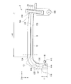
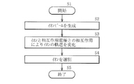
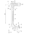
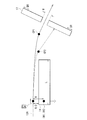
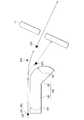
- FIG. 1 is a diagram illustrating an example of a schematic configuration of an ion implantation device according to an embodiment of the present disclosure. It is a figure showing an example of the cross-section structure in I-I' of the ion implantation apparatus shown in FIG. 5 is a flowchart illustrating an ion selection method according to an embodiment of the present disclosure. It is a figure explaining the principle of the selection method of the ion concerning one embodiment of this indication (interaction of stationary ion and an interaction electrode). It is a figure which shows an example of the fall time with respect to the distance of the ion and the interaction electrode by the ion selection method which concerns on one embodiment of this indication.
- FIG. 8 is a diagram showing a part of the trajectory of an ion beam of the ion implantation apparatus shown in FIG. 7.
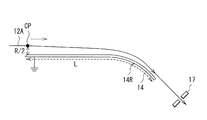
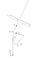
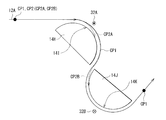
- FIG. 9A It is a figure showing an example of the schematic structure of the ion implantation apparatus concerning the modification A. It is a figure which shows an example of a structure of the principal part of the ion implantation apparatus shown in FIG. 9A. It is a figure which shows an example of schematic structure of the principal part of the ion implantation apparatus which concerns on the modification B. It is a figure which shows an example of schematic structure of the principal part of the ion implantation apparatus which concerns on the modification C. It is a figure which shows an example of schematic structure of the principal part of the ion implantation apparatus which concerns on the modification D. It is a figure which shows an example of schematic structure of the principal part of the ion implantation apparatus which concerns on the modification E.
- FIG. 16B is a diagram showing an ion beam of the ion implantation apparatus shown in FIG. 16A.
- Example 2 in which an interaction electrode is provided in the ion beam transport tube Modified
- Example A An example in which a slit is provided in the trajectory of the ion beam.
- FIGS. 9A to 9B Modification B: Example in which the surface of the interaction electrode has a curved surface...
- FIG. Modification C Example in which a magnetic field for adjusting the trajectory of the ion beam is provided.
- Modification D Example in which an electric field for adjusting the trajectory of the ion beam is provided...
- Fig. 12 Modification E: Example in which the surface of the interaction electrode has a curved surface...
- FIG. Modification F Example in which the surface of the interaction electrode has a curved surface and a magnetic field for adjusting the trajectory of the ion beam is provided...
- Fig. 14 Modification G: a part of the surface of the interaction electrode is a flat surface, Example in which another part is a curved surface...
- Fig. 15 Modification H: Example having multi-stage interaction electrodes... FIGS. 16A to 16B
- FIG. 1A illustrates an example of a schematic configuration of an ion implantation device 1 according to an embodiment of the present disclosure.
- FIG. 1B shows an example of a cross-sectional structure taken along the line II′ of the ion implantation apparatus 1 shown in FIG. 1A.
- the ion implantation apparatus 1 has an ion source 11C, an extraction electrode 11D, an ion beam transport tube 10, and an interaction electrode 14.
- the ion beam transport tube 10 transports the ion beam to the wafer 22.
- the ion beam transport tube 10 has, for example, an ion beam generator 11, an ion beam deflector 13, and an ion selector 14S, and are arranged in this order from one end to the other end.
- the ion beam transport tube 10 corresponds to a specific but not limitative example of “ion beam transport tube” of the present disclosure.
- the ion beam transport tube 10 has, for example, a stretched portion that stretches in the X-axis direction and the Y-axis direction, and a bent portion that connects the stretched portions.
- the wafer 22 corresponds to a specific but not limitative example of “ion beam irradiated body” of the present disclosure.
- the ion source 11C and the extraction electrode 11D are arranged in the ion beam generator 11, and the interaction electrode 14 is arranged in the ion selector 14S.
- a wafer processing chamber 20 is arranged, and the wafer 22 is arranged inside the wafer processing chamber 20.
- the ion beam generation unit 11 is a unit that generates an ion beam, and is configured, for example, as a stretching unit that stretches in the X-axis direction in FIG. 1A.
- An arc chamber 11A, a gas source 11B, an ion source 11C, and an extraction electrode 11D are arranged in the ion beam generator 11.
- the ion source 11C corresponds to a specific but not limitative example of “ion source” in the present disclosure.
- the lead electrode 11D corresponds to a specific but not limitative example of “lead electrode” in one embodiment of the present disclosure.
- the arc chamber 11A is for making a source gas serving as an ion source into plasma, and for example, a source magnet (not shown) is arranged in the Z-axis direction.
- a filament (not shown) is provided near the arc chamber 11A.
- a raw material gas is introduced into the arc chamber 11A from the gas source 11B, and a high voltage is applied by a filament (not shown) while a magnetic field is applied by a source magnet (not shown). Thereby, the source gas is turned into plasma and the ion source 11C is formed.
- the ion source 11C is for generating ions (desired ions) used for ion implantation, and contains a plurality of types of ions CP for the reason described below.
- the extraction electrode 11D is for generating the ion beam 12 from the ion source 11C.
- a plurality of types of ions CP containing desired ions are extracted from the ion source 11C by applying a predetermined voltage to the extraction electrode 11D, and thus the ion beam 12 containing a plurality of types of ions CP. Is generated.
- the ion beam deflection unit 13 filters desired ions from the ion beam 12 by filtering according to the mass-to-charge ratio (mass m/charge number q, hereinafter also referred to as “m/q”) of each ion. It is for.
- the ion beam deflection unit 13 is arranged, for example, between the ion beam generation unit 11 and the ion selection unit 14S, and is configured, for example, as a bent portion in FIG. 1A.
- the ion beam deflector 13 corresponds to a specific but not limitative example of “ion beam deflector” in one embodiment of the present disclosure.
- the ion beam deflection unit 13 is composed of, for example, a magnetic field type filter for applying a magnetic field to the ion beam or an electric field type filter for applying an electric field to the ion beam.
- the magnetic field type filter performs filtering based on the difference in momentum of each ion CP, and is composed of, for example, an analyzer magnet.
- a magnetic field When a magnetic field is applied to the ion beam 12, the direction (orbit) in which the ion beam 12 is transported is bent due to the balance between the centrifugal force and the Lorentz force.
- the degree of bending of the trajectory of the ion beam 12 depends on the mass-to-charge ratio m/q of the ions. Therefore, in the ion beam deflecting unit 13 configured by the magnetic field type filter, the magnetic field is adjusted so that desired ions among the plurality of types of ions included in the ion beam 12 pass through the ion beam deflecting unit 13.
- ions having a larger mass-to-charge ratio m/q (heavier) than the desired ions become the ion beam 12B having a small degree of bending and collide with the inner wall surface of the ion beam transport tube 10 to be removed.
- Ions having a mass-charge ratio m/q smaller (lighter) than the desired ions become the ion beam 12C having a large degree of bending, and collide with the inner wall surface of the ion beam transport tube 10 to be removed.
- the ion beam 12A containing the desired ions is extracted. The selection of the ion CP by the magnetic field type filter will be described later.
- the electric field type filter filters by the energy difference of each ion CP.
- the direction (orbit) in which the ion beam 12 is transported is bent due to the balance between the centrifugal force and the Coulomb force.
- the electric field is adjusted so that desired ions among the plurality of types of ions included in the ion beam 12 pass through the ion beam deflecting unit 13.
- ions (heavy) having a larger m/q and ions (smaller) having a smaller m/q than the desired ions collide with the inner wall surface of the ion beam transport tube 10 and are removed.
- the ion beam 12A containing the desired ions is extracted. The selection of the ion CP by the electric field type filter will be described later.
- the ion beam transport tube 10 is bent 90° from the X-axis direction to the Y-axis direction, but it is not limited to this.
- the ion beam transport tube 10 may be bent at an angle other than 90°.
- the ion selecting unit 14S determines the size of the mass m/(charge number q) 2 (hereinafter also referred to as “m/q 2 ”) of each ion CP from the ion beam 12A selected by the ion beam deflecting unit 13.
- the desired ions are selected by filtering according to.
- unnecessary ions contained in the ion beam 12A are further removed, and the ion beam 12D of desired ions is selected from the ion beam 12A.
- the ion selecting unit 14S is configured as, for example, a stretching unit that stretches in the Y-axis direction in FIG. 1A.
- the interaction electrode 14 is arranged in the ion selector 14S.
- the interaction electrode 14 corresponds to a specific but not limitative example of “interaction portion” of the present disclosure.
- the interaction electrode 14 changes the trajectory of the ion beam 12A by the interaction between the plurality of ions CP included in the ion beam 12A and the image charge IM.
- the interaction electrode 14 is formed of, for example, a conductor.
- the interaction electrode 14 is, for example, a plate-shaped member that extends in the uniaxial direction, and is arranged in the ion beam transport tube 10 so as to extend substantially parallel to the extending direction of the ion beam transport tube 10, for example.
- the surface of the interaction electrode 14 is preferably flat, but not limited to this, and may have a curved surface.
- the surface of the interaction electrode 14 has a deviation of the distance between the ion beam 12A and the surface of the interaction electrode 14 within a range of ⁇ 10 mm. It is preferable.
- the interaction electrode 14 is fixed at a predetermined electric potential.
- the predetermined potential is, for example, the ground potential.
- the ion beam 12A in the ion selector 14S is transported near the interaction electrode 14. Specifically, in the ion beam 12A, for example, as shown in FIG. 1B, the distance R1 between the ion beam 12A and the interaction electrode 14 is smaller than the distance R2 between the ion beam 12A and the wall surface of the ion beam transport tube 10. The location is transported.
- a virtual trajectory of the ion beam 12A when there is no interaction with the interaction electrode 14 is shown by a broken line LN.
- the trajectory of the ion beam 12A is drawn at a predetermined distance in a linear trajectory as shown in FIG. 1, and then, due to the influence of the interaction electrode 14, the interaction electrode 14 is located closer to the interaction electrode 14 than the broken line LN. Can be bent into.
- the selection of the ions CP by the ion selection unit 14S will be described later.
- a wafer processing chamber 20 is provided at the other end of the ion beam transport tube 10.
- a base 21 that can be normally driven is provided inside the wafer processing chamber 20, and a wafer 22 is held on the base 21.
- the wafer 22 is irradiated with the ion beam 12D on the base 21.
- the base 21 may be rotationally driven.
- a Faraday cup 16A is provided near the other end of the ion beam transport tube 10 (ion beam exit 10D).
- An ammeter 16B is connected to the Faraday cup 16A and the base 21. The ammeter 16B measures the amount of beam current used for ion implantation, and thus the amount of ion implantation can be controlled according to the obtained amount of current.
- FIG. 2 shows a flow of ion selection in the ion selection unit 14S.
- the ion beam generation unit 11 generates an ion beam 12 containing a plurality of types of ions CP, and the ion beam deflection unit 13 generates a charge mass ratio ( Ions are selected based on m/q) to generate the ion beam 12A (step S2).
- ions are selected in the ion selecting unit 14S.
- the trajectory of the ion beam is changed by the interaction between the interaction electrode 14 and the ion beam 12A (step S3).
- desired ions are selected from the plurality of types of ions CP included in the ion beam 12A (step S4). In this way, desired ions are selected from the plural types of ions CP.
- step S3 the trajectory of the ion beam 12A is changed by the interaction between the image charge IM in the interaction electrode 14 and the plurality of types of ions CP for the plurality of types of ions CP.
- the ion beam 12A is assumed to include, for example, a first ion CP1 and a second ion CP2 as a plurality of types of ions.
- the first ion CP1 has a first mass m1 and a first charge number q1.
- the second ion CP2 has a second mass m2 and a second charge number q2.
- the interaction between the interaction electrode 14 and the ion beam 12A causes the difference between m1/(q1) 2 and m2/(q2) 2 to cause the first trajectory and the second trajectory of the first ion CP1.
- the second orbits of the ions CP2 of the are different from each other.
- the interaction between the interaction electrode 14 and the ion beam 12A removes unnecessary ions from the plurality of types of ions CP based on the mass m/(number of charges q) 2 . Extract (select) desired ions.
- the ion beam generator 11 generates the ion beam 12, and the ion beam deflector 13 selects the ion CP based on the mass-to-charge ratio m/q to extract the ion beam 12A containing desired ions. ..
- the ions CP are selected based on the mass m/(the number of charges q) 2 , the unnecessary ions contained in the ion beam 12A are further removed, and the ion beam 12D of the desired ion is selected. And irradiate the wafer.
- the filtering of the ions CP in the ion beam deflecting unit 13 and the ion selecting unit 14S of the ion implanter 1 of the present embodiment will be described in detail below.
- the ion beam 12 generated by the ion beam generator 11 contains unnecessary ions in addition to desired ions to be implanted. Unwanted ions mixed in the ion beam 12 are the gas of the gas source 11B or impurities contained therein, the metal element derived from the metal member forming the arc chamber 11A, and tungsten emitted from a filament (not shown). Is. Generally, BF 3, B 2 F 6 or the like is used as an ion source of boron (B). As the phosphorus (P) ion source, POCl 3 , PF 3 , PH 3 , or the like is used. AsH 3 or the like is used as an arsenic (As) ion source.
- arc chamber 11A In the arc chamber 11A, in addition to desired ions (B, P, or As ions), single ions of hydrogen (H), oxygen (O), and fluorine (F) contained in the ion source, and B , P, As and various ions such as molecular ions are released as unnecessary ions. Further, iron (Fe), nickel (Ni), chromium (Cr), tungsten (W), molybdenum (Mo), etc. that form the arc chamber 11A and filament (not shown) are also partially ionized and released. It becomes unnecessary ions.
- the filtering of the ion CP by the ion beam deflection unit 13 composed of a magnetic field type filter will be described.
- a magnetic field having a magnetic flux density B is applied in the Z-axis direction to the ion beam 12 containing the plural types of ions CP generated by the ion beam generation unit 11.
- Each ion CP receives the Lorentz force F due to the magnetic field, and the orbit is bent.
- the orbital radius is r
- the mass of ions is m
- the number of charges is q
- equation (2) shows the balance between the centrifugal force and the Lorentz force.
- the orbital radius r is determined by the mass-to-charge ratio m/q.
- the ion beam 12B of unnecessary ions whose mass-to-charge ratio m/q is larger (heavier) than the desired ions has a large orbit radius r and collides with the inner wall surface of the ion beam transport tube 10 to be removed.
- the ion beam 12C of unnecessary ions whose mass-to-charge ratio m/q is smaller (lighter) than the desired ions has a small orbit radius r and collides with the inner wall surface of the ion beam transport tube 10 to be removed.
- the ion beam deflector 13 can select the ions CP according to the mass-to-charge ratio m/q and take out the ion beam 12A containing desired ions.
- equation (4) Given an electromagnetic field having a magnetic field of magnetic flux density B and an electric field Ef, the equation of motion of the ion CP moving in the electromagnetic field is shown by equation (4).
- the ions CP having different mass-to-charge ratios m/q move in different orbits, like the magnetic field type filter.
- the ion beams 12B and 12C of unnecessary ions can be collided with the inner wall surface of the ion beam transport tube 10, or can be shielded by providing a slit, and the ion beam 12A containing desired ions can be passed through and extracted.
- the ions CP are selected according to the mass-to-charge ratio m/q, and the ion beam 12A containing desired ions can be extracted.
- the ion beam deflecting unit 13 is an electric field type filter that applies the electric field Ef
- the equation in which B is 0 (zero) is established in the equation (6)
- the ions CP having different mass-to-charge ratios m/q have different trajectories. Exercise.
- the ion beam deflection unit 13 (electric field type filter) can select the ions CP by the mass-to-charge ratio m/q and take out the ion beam 12A containing desired ions.
- the filtering of the ions CP by the ion selector 14S will be described.
- the ion selector 14S removes unnecessary ions from a plurality of types of ions CP based on the mass m/(charge number q) 2 and selects desired ions.
- the ion beam deflector 13 sorts out the ions CP based on the mass-to-charge ratio m/q, but the ion beam 12 generated by the ion beam generator 11 has a mass charge as unnecessary ions. Ions CP having a similar ratio m/q are included.
- a molybdenum (Mo) ion ( 94 Mo 3 ) can be used as an ion whose mass-to-charge ratio m/q is close to that of P ion ( 31 P + , hereinafter referred to as P + ).
- Table 1 Is the number of charges q of each ion CP of P + , Mo 3+ , and W 6+ , the unified atomic mass unit u, the mass-to-charge ratio u/q, and the mass-to-charge ratio difference ⁇ (u/q)( %) is shown.
- the mass-to-charge ratios u/q of P + , Mo 3+ , and W 6+ are close to each other. Separation of P + , Mo 3+ , and W 6+ is difficult by the filtering by the ion beam deflection unit 13. For example, in the ion beam 12A obtained for the purpose of P + selection, unnecessary ions of Mo 3+ and W 6+ is mixed. Therefore, when the wafer 22 is irradiated with the ion beam 12A, Mo 3+ and W 6+ are also ion-implanted in addition to P + . Such metal contamination by unnecessary ions has a great influence on the characteristics and life of the semiconductor element. Therefore, it is required to improve the ion separation performance so as to remove unnecessary ions and select desired ions.
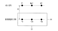
- FIG. 3 illustrates the principle of the ion selection method in the ion selection unit 14S (interaction between the stationary ion CP and the interaction electrode 14).
- P + , Mo 3+ , and W 6+ will be described as an example of the three types of ions CP mixed in the ion beam 12A. It is assumed that three types of ions CP (P + , Mo 3+ , W 6+ ) separated by a distance of R/2 are stationary from the interaction electrode 14 fixed at a constant potential (eg, ground potential). To do.
- the equation of motion of ions is shown by the above equation (4).
- the ions CP interact with the image charge IM corresponding to each ion CP in the interaction electrode 14.
- the image charge IM has a polarity opposite to that of the ions CP and has the same number of charges.
- the depth of the image charge IM in the interaction electrode 14 is equal to the distance between the ion CP and the interaction electrode 14.
- the distance between the ion CP and the image charge IM is R.
- the ions CP and the image charge IM interact with each other at a distance R by a Coulomb force and attract each other.
- the Coulomb force with the image charge IM of the ion CP is expressed by equation (7).
- ⁇ is a dielectric constant.
- the formula (8) is derived from the formula (4) and the formula (7).
- the motion of the ion CP is determined by m/q 2 . That is, the three types of ions CP (P + , Mo 3+ , W 6+ ) have similar mass-to-charge ratios m/q, but the magnitudes of m/q 2 are different, and they are separated from each other. It is possible.
- FIG. 4A shows the fall time of the ion CP with respect to the distance between the ion CP and the interaction electrode 14.
- the fall time means that each ion CP reaches the surface of the interaction electrode 14 by interacting with the image charge IM at the position of the distance R from the position R/2 away from the surface of the interaction electrode 14. It is the time to (fall).
- the three types of ions CP (P + , Mo 3+ , W 6+ ) are indicated by straight lines a, b, and c, respectively. It can be seen from FIG. 4A that the three types of ions CP (P + , Mo 3+ , W 6+ ) have different drop times to the interaction electrode 14.
- FIG. 4B shows the horizontal distance to the fall with respect to the distance between the ion CP and the interaction electrode 14.
- three types of ions CP (P + , Mo 3+ , W 6+ ) are shown by curves d, e, and f, respectively.
- the three types of ions CP (P + , Mo 3+ , W 6+ ) are extracted at a predetermined extraction voltage.
- the ions CP move substantially parallel to the surface of the interaction electrode 14 when approaching the interaction electrode 14, and this direction is referred to as the horizontal direction.
- the velocity v when the ion CP reaches the interaction electrode 14 is derived from the equation (1) and is represented by the equation (9).
- the distance between the ion CP and the interaction electrode 14 is R/2 when approaching the interaction electrode 14, the distance between the ion CP and the image charge IM is R.
- the distance between the ion and the interaction electrode 14 or the image charge IM at the time when the ion CP reaches the interaction electrode 14 is also referred to as an “initial distance”. While passing on the interaction electrode 14, the ion CP interacts with the image charge IM and gradually falls on the interaction electrode 14.
- the horizontal distance to the drop shown in FIG. 4B is a distance that the ion CP moves in the horizontal direction before falling onto the interaction electrode 14 when the ion CP passes over the interaction electrode 14 as described above. .. From FIG. 4B, when the initial distance between the ion CP and the interaction electrode 14 is 5 ⁇ m (the initial distance between the ion CP and the image charge IM is 10 ⁇ m), P + does not fall to the interaction electrode 14. Move about 44 cm. Also, Mo 3+ moves about 26 cm before falling onto the interaction electrode 14. Also, W 6+ moves about 18 cm before falling on the interaction electrode 14. As described above, the horizontal distance until falling depends on the magnitude of m/q 2 of each ion CP.
- the horizontal length L of the interaction electrode 14 is set to be less than the horizontal distance until the desired ions fall and more than the horizontal distance until the unwanted ions fall, the unwanted ions collide with the interaction electrode 14. The removed ions of interest pass over the interaction electrode 14.
- FIG. 5 illustrates the principle of the ion selection method in the ion selection unit 14S (interaction between moving ions and the interaction electrode).
- an ion beam 12A containing P + and W 6+ When the extraction voltage is 30 KeV, the velocity v of the ion beam 12A is 4.3 ⁇ 10 5 m/sec.
- the initial distance R/2 between the ion CP (P + and W 6+ ) in the ion beam 12A and the interaction electrode 14 is 5 ⁇ m, and the ion CP (P + and W 6+ ) and the image charge IM are The initial distance R between them is 10 ⁇ m.
- P + and -1 interact with the image charge IM of ⁇ 1 valence by Coulomb force CF(P).
- W 6+ interacts with the ⁇ 6 valence image charge IM by Coulomb force CF(W).
- the length L of the interaction electrode 14 in the horizontal direction is 40 cm, so that P + can pass and W 6+ can be removed.
- Mo 3+ is not shown in FIG. 5, it can be removed similarly to W 6+ .
- the horizontal length L of the interaction electrode 14 may be set to 20 cm so that P + passes and W 6+ is removed. Can not remove Mo 3+ if Mo 3+ coexist, can be applied in the case intermixture amount of Mo 3+ in the ion beam 12A is very small.
- the distance R at which P + falls is 9 ⁇ m
- the distance at which W 6+ falls is 17 ⁇ m.
- P + passes through the ion selector 14S
- W + 6+ is removed by the ion selector 14S.
- phosphorus (P + ) passes through the ion selector 14S.
- Tungsten (W 6+ ) is removed by the ion selection unit 14S.
- the horizontal length L of the interaction electrode 14 is set so as to satisfy the expression (12).
- desired ions mass m, charge number q
- heavier ions ⁇ (mass 2 m, charge number 2q), (mass 3 m, charge number 3q),... nm, the number of charges nq) (n is an integer of 2 or more) ⁇ collides with the interaction electrode 14 and cannot pass therethrough.
- FIG. 6 shows an example of the configuration of the main part (ion selection part) of the ion implantation apparatus 1 shown in FIG. 1A.
- P + , Mo 3+ , and W 6+ are illustrated as the ion CP, but the ion CP is not limited to this and can be applied to other ions CP.
- the interaction electrode 14 shown in FIG. 6 interacts with, for example, the ion beam 12A including the first ion CP1 and the second ion CP2 having a mass-to-charge ratio of m/q approximate to select a desired ion. It is for.
- the first ion CP1 is a desired ion
- the second ion CP2 is an unnecessary ion.
- the first ion CP1 has a first mass m1 and a first charge number q1.
- the second ion CP2 has the second mass m2 and the second charge number q2.
- the first ion CP1 interacts with the image charge IM1 inside the interaction electrode 14 when passing over the interaction electrode 14 at a velocity v.
- the second ion CP2 also interacts with the image charge IM2 inside the interaction electrode 14 as it passes over the interaction electrode 14 at velocity v.
- the initial distance between the surface of the interaction electrode 14 and the ion beam 12A is R/2, and the orbits of the surface of the interaction electrode 14 and the ion beam 12A are substantially parallel.
- substantially parallel means in a narrow sense that the surface of the interaction electrode 14 and the trajectory of the ion beam 12A are parallel within the error range of R/2.
- the surface of the interaction electrode 14 and the trajectory of the ion beam 12A are substantially parallel in the narrow sense, the interaction between the ion beam 12A and the interaction electrode 14 occurs efficiently.
- a broad sense it means that the surface of the interaction electrode 14 and the trajectory of the ion beam 12A are parallel within a range of ⁇ 10 mm. Since the surface of the interaction electrode 14 and the trajectory of the ion beam 12A are substantially parallel in a broad sense, the effect can be more easily obtained.
- the first ion CP1 and the image charge IM1 behave as charged particles separated by the distance R.
- the first ion CP1 and the image charge IM1 interact with each other by Coulomb force, and the first ion CP1 gradually approaches the interaction electrode 14.
- the second ion CP2 and the image charge IM2 interact with each other by Coulomb force, and the second ion CP2 gradually approaches the interaction electrode 14. That is, the first ion CP1 and the second ion CP2 drop to the interaction electrode 14.
- the interaction electrode 14 generates a first orbit of the first ion CP1 and a second orbit of the second ion CP2 by the difference between m1/(q1) 2 and m2/(q2) 2. Different from each other.
- the length L of the interaction electrode 14 in the extending direction (Y-axis direction) so that the second ion CP2 collides with the interaction electrode 14 and the first ion CP1 passes without colliding with the interaction electrode 14.
- the initial distance R/2 and the like between the interaction electrode 14 and the first and second ions CP1 and CP2 are adjusted.
- the second ions CP2 can be removed and the first ions CP1 can be taken out (selected), and the separation performance (desired ions and unnecessary ions) of impurity ions used for ion implantation can be improved.
- the extraction electrode 11D preferably extracts a plurality of types of ions with an extraction voltage of 10 mV or more and 1 MV or less, for example. Desired ions and unwanted ions are extracted with the same extraction voltage.
- the extraction voltage By controlling the extraction voltage, the velocity of each ion can be controlled, and the time when each ion and the interaction electrode 14 interact with each other and the distance over which they interact can be controlled. It is possible to improve the separation performance of impurity ions (desired ions and unnecessary ions) used for ion implantation.
- the distance between the ion beam 12A and the interaction electrode 14 is preferably, for example, 0.1 nm or more and 10 mm or less. The closer the distance between the ion beam 12A and the interaction electrode 14, the greater the interaction. At distances greater than 10 mm, the interactions are not large enough for ion selection. When it is closer than 0.1 nm, it becomes difficult to prevent desired ions from colliding with the interaction electrode 14.
- the length L of the interaction electrode 14 in the extending direction (Y-axis direction) is preferably, for example, 1 mm or more and 30 m or less.
- the ion beam 12A is preferably transported substantially parallel to the surface of the interaction electrode 14 within an error range of ⁇ 10 mm. If it exceeds ⁇ 10 mm, stable interaction between the ion CP and the interaction electrode 14 may be difficult.
- the time for the ion beam 12A to pass through the part that interacts with the interaction electrode 14 (the time for the interaction electrode 14 and the ion beam 12A to interact) is defined as time Tf.
- the time until at least one of the plurality of types of ions CP falls on the interaction electrode 14 while passing through the portion of the trajectory of the ion beam 12A that interacts with the interaction electrode 14 is defined as time Tc. It is preferable that Tf and Tc satisfy the relationship of Tf ⁇ 0.001Tc, for example. Thereby, it is possible to adopt a configuration in which the ions can be favorably selected in the ion selector 14S.
- the ion implanter 1 is arranged so that the trajectory of the ion beam 12A follows the surface of the interaction electrode 14.
- the interaction electrode 14 has a planar shape having a constant length L in the horizontal direction as shown in FIG. 1A, but is not limited to this and may have a curved surface.
- the ion implantation process is a very important process that affects device characteristics and reliability of the semiconductor.
- boron (B) is used to form a p-type semiconductor
- a dopant such as phosphorus (P) or arsenic (As) is used to form an n-type semiconductor by using an ion implantation apparatus.
- the acceleration energy for implanting into the wafer determines the implantation depth, and the total amount of ion implantation (dose) depending on the irradiation current amount and time is freely and extremely controlled so as to obtain desired device characteristics. It can be adjusted with high controllability.
- the ion implantation apparatus 100 in order to explain the operation and effect of the ion implantation apparatus 1, the ion implantation apparatus 100 according to the reference embodiment will be described.
- FIG. 7 shows a schematic configuration of the ion implantation device 100 according to the reference embodiment.
- the general ion implantation apparatus 100 includes, for example, an ion beam transport tube 110, an arc chamber 111A, a gas source 111B, an ion source 111C, an extraction electrode 111D, an ion beam deflector 113, a Faraday cup 116A, an ammeter 116B, and a wafer processing chamber. It is composed of 120 and a base 121.
- the ion beam 112 is extracted by the extraction electrode 111D from the ion source 111C formed by the arc chamber 111A, the gas source 111B, and the like.
- the extracted ion beam 112 is selected by the difference in ion momentum or energy while the trajectory of the ion beam deflector 113 is bent. That is, the ion beam 112B of ions with a large (heavy) m/q value and the ion beam 112C of ions with a small (light) m/q are filtered. An ion beam 112A containing desired ions to be used for ion implantation is extracted. The extracted ion beam 112A is guided to the wafer processing chamber 120 and irradiated on the wafer 122.
- the ion beam 112A includes a plurality of types of ions (for example, the first ion CP1 and the second ion CP2) with which the mass-to-charge ratio m/q approximates.
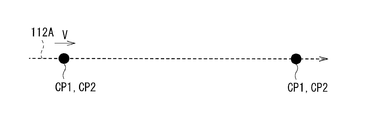
- FIG. 8 shows a part of the trajectory of the ion beam after passing through the ion beam deflection unit 113 of the ion implantation apparatus shown in FIG.
- the mass-to-charge ratio m1/q1 of the first ion CP1 and the mass-to-charge ratio m2/q2 of the second ion CP2 are close to each other, the first ion CP1 and the second ion CP2 have passed through the ion beam deflector 113. After that, the wafer 122 is transported on the same track without being separated and is injected into the wafer 122. For example, it is very difficult to separate ions with a mass-to-charge ratio difference of 1% even with an ion implanter having a high-performance mass analysis capability.
- the ion beam transport tube 10 is provided with the ion selector 14S having the interaction electrode 14 fixed at a predetermined potential.
- the interaction beam 14 interacts with the ion beam 12A including the first ion CP1 and the second ion CP2 whose mass-to-charge ratios are similar to each other, so that the first ion CP1 And the second orbit of the second ion CP2 are different from each other.
- the desired ion and the unwanted ion having a mass-to-charge ratio of m/q are mixed in the ion beam containing the desired ion to be implanted. Also, unnecessary ions can be removed. This can improve the separation performance of impurity ions used for ion implantation (desired ions and unnecessary ions).
- semiconductor element characteristics and reliability can be improved. For example, in a semiconductor imaging device, noise such as white spots is suppressed, and image quality can be improved.
- the pressure resistance is improved and the reliability is enhanced.
- the semiconductor memory device the data holding characteristic of the stored information is improved and the reliability is enhanced.
- FIG. 9A shows an example of an ion implantation apparatus 1A as a modified example A.
- a slit 17 is provided at a position subsequent to the interaction electrode 14 and at a position where the trajectory of desired ions and the trajectory of unwanted ions are sufficiently separated from each other. Except for the above, the configuration is similar to that of the ion implantation apparatus 1.
- FIG. 9B shows an example of a configuration of a main part of the ion implantation apparatus shown in FIG. 9A.
- the slit 17 is configured to pass the first ion CP1 and shield the second ion CP2 when the ion beam 12A includes the first ion CP1 and the second ion CP2.
- the slit 17 passes P + and blocks Mo 3+ and W 6+ , for example. It is configured.
- the slit 17 can be adjusted in position in a predetermined direction DR, for example, and the slit width W can also be adjusted.
- the slit 17 may be fixed.
- the time for the ion beam 12A to pass through the part that interacts with the interaction electrode 14 (the time for the interaction electrode 14 and the ion beam 12A to interact) is defined as time Tf.
- the time until at least one of the plurality of types of ions CP falls on the interaction electrode 14 while passing through the portion of the trajectory of the ion beam 12A that interacts with the interaction electrode 14 is defined as time Tc.
- Tf and Tc satisfy equation (13).
- the ion beam 12A has, for example, a first ion CP1 having a first mass m1 and a first charge number q1 and a first ion CP1 having a second mass m2 and a second charge number q2. It contains two ions CP2.
- the first ion CP1 interacts with the image charge IM1 in the interaction electrode 14 by Coulomb force, and gradually approaches the interaction electrode 14.
- the second ion CP2 interacts with the image charge IM2 in the interaction electrode 14 by Coulomb force, and gradually approaches the interaction electrode 14.
- the length L of the interaction electrode 14 in the extending direction is adjusted to be short so that neither the first ion CP1 nor the second ion CP2 falls on the interaction electrode 14. Due to the interaction with the interaction electrode 14, the first orbit of the first ion CP1 and the second orbit of the second ion CP2 are different from each other.
- the position of the slit 17 is adjusted so that the first ion CP1 passes and the second ion CP2 does not pass. In this way, the first ions CP1 can be extracted (selected).
- the ion implanter 1A As in the ion implanter 1, even when the ion beam containing the desired ion to be implanted contains the desired ion and the unnecessary ion having a mass-charge ratio m/q of approx. , Unnecessary ions can be removed. Further, in the ion implanter 1A, the distance R/2 between the ion beam 12A and the interaction electrode 14 can be reduced, and the length L of the interaction electrode 14 can be shortened. This makes it possible to reduce the size of the ion implantation device.
- the surface of the interaction electrode 14 has a planar shape, but is not limited to this, and may have a curved surface.
- FIG. 10 shows an example of a main part of an ion implantation apparatus 1B as a modified example B.
- the interaction electrode 14 has a curved surface portion 14R.
- the trajectory of the ion beam 12A is bent toward the interaction electrode 14 due to the interaction with the interaction electrode 14, and the curvature of the curved surface portion of the interaction electrode 14 is provided so as to match the trajectory of the ion beam 12A. ing. Except for the above, it has the same configuration as the ion implantation apparatus 1.
- the ion implanter 1B like the ion implanter 1, even if the desired ion and the unwanted ion having a mass-to-charge ratio of m/q are mixed in the ion beam containing the desired ion, it is unnecessary. Ions can be removed. Further, in the ion implanter 1B, the surface of the interaction electrode 14 has a shape that fits the trajectory of the ion beam 12A, and the distance and time for the ion beam 12A and the interaction electrode 14 to interact can be secured. This makes it possible to reduce the size of the ion implantation device.
- FIG. 11 shows an example of a main part of an ion implantation apparatus 1C as a modification C.
- a magnetic field 30A that supplementarily changes the orbit is provided in a part of the orbit of the ion beam 12A.
- the part of the orbit is a portion where the orbit changes due to the interaction between the first ion CP1 and the second ion CP2 and the interaction electrode 14. Except for the above, it has the same configuration as the ion implanter 1A.
- the ion implanter 1C like the ion implanter 1, even if the desired ion and the unwanted ion having a mass-to-charge ratio of m/q are mixed in the ion beam containing the desired ion, it is not necessary. Ions can be removed. Further, the ion implantation apparatus 1C has a magnetic field 30A for orbit adjustment, and slits are provided so that desired ions (first ions CP1) pass and unnecessary ions (second ions CP2) do not pass. Even if 17 is fixed, it is easy to adjust.
- FIG. 12 shows an example of a main part of an ion implantation apparatus 1D as a modification D.
- An electric field 31A that supplementarily changes the trajectory is provided on a part of the trajectory of the ion beam 12A.
- the part of the orbit is a portion where the orbit changes due to the interaction between the first ion CP1 and the second ion CP2 and the interaction electrode 14. Except for the above, it has the same configuration as the ion implanter 1A.
- the ion implanter 1D similarly to the ion implanter 1, even if the ion beam containing the desired ion to be implanted is mixed with the desired ion and the unnecessary ion having a mass-to-charge ratio of m/q approximate, it is unnecessary. Ions can be removed. Further, in the ion implanter 1D, an electric field 31A for orbit adjustment is applied, and a slit is formed so that a desired ion (first ion CP1) passes and an unnecessary ion (second ion CP2) does not pass. Even if 17 is fixed, it is easy to adjust.
- the surface of the interaction electrode 14 has a planar shape, but is not limited to this, and may have a curved surface.
- FIG. 13 shows an example of a main part of an ion implantation apparatus 1E as a modification E.
- the interaction electrode 14A has a curved surface portion 14B.
- the interaction electrode 14A has a cylindrical shape or a spherical shape.
- the columnar or spherical interaction electrode 14A has a curved surface portion 14B on the surface that interacts with the ion beam.
- the inside of the interaction electrode 14 may have a hollow structure.
- the traveling direction of the ion beam 12A is bent with a predetermined curvature.
- the magnetic field 32A and the like are adjusted so that the traveling direction of desired ions contained in the ion beam 12A is substantially parallel to the curved surface portion 14B of the interaction electrode 14A.
- the ion beam 12A includes a first ion CP1 having a first mass m1 and a first charge number q1, a second mass m2, and a second charge number q2. It includes the second ion CP2 that it has, and the third ion CP3 that has the third mass m3 and the third charge number q3.
- the first ion CP1, the second ion CP2, and the third ion CP3 pass near the interaction electrode 14A, the first ion CP1, the second ion CP2, and the third ion CP3 interact with the interaction electrode 14A and undergo an orbit depending on the difference in the number of charges. Changes.
- the first ion CP1 is a desired ion, and due to the influence of the bending of the magnetic field 32A in the traveling direction and the interaction with the interaction electrode 14A, the first ion CP1 travels on a trajectory substantially parallel to the curved surface portion 14B. Has been adjusted.
- the second ion CP2 having a larger number of charges than the first ion CP1 is bent in the traveling direction by the magnetic field 32A, but the influence of the interaction with the interaction electrode 14A is larger than that of the first ion CP1 and the interaction is large. It falls to the electrode 14A.
- the third ion CP3 having a smaller number of charges than the first ion CP1 is bent in the traveling direction by the magnetic field 32A, but the influence of the interaction with the interaction electrode 14A is smaller than that of the first ion CP1. It goes away from the surface of the electrode 14A.
- the magnetic field 32A or the like so that desired ions travel on an orbit substantially parallel to the curved surface portion 14B, the second ions CP2 and the third ions CP3, which are unnecessary ions, are removed,
- the first ion CP1 that is a desired ion can be extracted. Except for the above, it has the same configuration as the ion implantation apparatus 1.
- the ion implanter 1E like the ion implanter 1, even if the desired ion and the unwanted ion having a mass-to-charge ratio of m/q are mixed in the ion beam containing the desired ion, it is unnecessary. Ions can be removed. Further, in the ion implanter 1E, the surface of the interaction electrode 14 has a curved surface, so that the space of the interaction electrode 14A can be saved. Further, since the distance where the ion beam 12A and the interaction electrode 14A interact can be secured long, it is possible to increase the distance R/2 between the ion beam 12A and the surface of the interaction electrode 14A.
- FIG. 14 shows an example of main parts of an ion implantation apparatus 1F as a modification F.
- the magnitude of the interaction with the interaction electrode 14 is different due to the difference in the number of charges, and the second ion CP2 is better than the first ion CP1. Travel in an orbit closer to the interaction electrode 14A. Of the first ion CP1 and the second ion CP2 whose orbits are different in this way, the first ion CP1 passes through the slit 17 and the second ion CP2 does not pass through the slit. It is arranged. Except for the above, it has the same configuration as the ion implanter 1E.
- the ion implanter 1F As in the ion implanter 1E, even if the desired ion and the unwanted ion having a mass-to-charge ratio of m/q are mixed in the ion beam containing the desired ion, it is unnecessary. Ions can be removed. Further, in the ion implantation apparatus 1F, by adjusting the magnetic field 32A and adjusting the slit 17, it is possible to allow desired ions (first ions CP1) to pass and to prevent unwanted ions (second ions CP2) from passing. it can.
- the surface of the interaction electrode 14A that interacts with the ion beam 12A is only the curved surface portion, but the invention is not limited to this, and may have a configuration having both a flat surface portion and a curved surface portion. ..
- FIG. 15 shows an example of a main part of an ion implantation apparatus 1G as a modified example G.
- the interaction electrode 14G has a first portion 14C whose surface is a flat surface portion 14D and a second portion 14E whose surface is a curved surface portion 14F.
- the interaction between the ion beam 12A and the interaction electrode 14 is performed in both the flat surface portion 14D and the curved surface portion 14F. Except for the above, it has the same configuration as the ion implanter 1F.
- the ion implanter 1F As in the ion implanter 1E, even if the desired ion and the unwanted ion having a mass-to-charge ratio of m/q are mixed in the ion beam containing the desired ion, it is unnecessary. Ions can be removed.
- the ion beam 12A and the interaction electrode 14G interact with each other in the flat surface portion 14D and the curved surface portion 14F of the interaction electrode 14G, and a long distance in which the ion beam 12A and the interaction electrode 14G interact can be secured.
- the above-mentioned ion implanter 1E has a configuration in which one interaction electrode having a curved surface portion is provided, but it is also possible to employ a configuration in which a plurality of interaction electrodes are provided and ions are selected by a multistage electrode.
- FIG. 16A shows an example of a main part of an ion implantation apparatus 1H as a modification H.
- the ion implanter 1H has a first interaction electrode 14H and a second interaction electrode 14J.
- the first interaction electrode 14H has a curved surface portion 14I.
- the second interaction electrode 14J has a curved surface portion 14K.
- the ion beam 12A includes the first ion CP1 and the second ion CP2.
- the first ion CP1 is a desired ion.
- the second ion CP2 is an unnecessary ion.
- the second ion CP2 is an ion having a larger number of charges than the first ion CP1.
- the second ion CP2 has a spread in a cross section perpendicular to the traveling direction as shown in FIG. 16B.
- the half closer to the first interaction electrode 14H is the lower second ion CP2A, and the half farther from the first interaction electrode 14H is the upper half. 2 ion CP2B.
- the traveling direction of the ion beam 12A is bent with a predetermined curvature.
- the magnetic field 32A and the like are adjusted so that the traveling direction of the first ions CP1 included in the ion beam 12A is substantially parallel to the curved surface portion 14I of the first interaction electrode 14H.
- the lower second ion CP2A on the side closer to the first interaction electrode 14H drops to the first interaction electrode 14H.
- the first ion CP1 that has passed through the first interaction electrode 14H approaches the second interaction electrode 14J.
- the upper second ion CP2B does not fall to the first interaction electrode 14H and approaches the second interaction electrode 14J in the upper half on the side far from the first interaction electrode 14H.
- the magnetic field 32B to the first ion CP1 and the upper second ion CP2B, the traveling directions of the first ion CP1 and the upper second ion CP2B are bent with a predetermined curvature.
- the magnetic field 32B and the like are adjusted so that the traveling direction of the first ion CP1 is substantially parallel to the curved surface portion 14K of the second interaction electrode 14J.
- the upper second ion CP2B is on the side closer to the second interaction electrode 14J and drops onto the second interaction electrode 14J. There is no particular boundary between the lower second ion CP2A and the upper second ion CP2B, but about half drops to the first interaction electrode 14H, and the other half goes to the second interaction electrode 14J. And is configured to fall.
- the ion implanter 1H similarly to the ion implanter 1, even if the desired ion and the unwanted ion having a mass-to-charge ratio of m/q are mixed in the ion beam containing the desired ion, it is not necessary. Ions can be removed. Further, even when the unwanted ions are in the form of a beam having a divergence, they can be separated in a large number of times by the interaction with the multistage interaction electrodes.
- the ion implantation device having the interaction electrode made of a conductor has been described, but the present invention is not limited to this, and instead, a configuration having an interaction part made of a dielectric substance. It can also be applied to the ion implantation device of.
- the selection of 31 P + , 94 Mo 3+ , and 186 W 6+ is described, but the present invention is not limited to this, and ions that separate other ions are also described. Applicable to injection equipment. For example, it is possible to adopt a configuration in which 92 Mo 3+ is selectively removed from 31 P + . Further, it can be configured to remove by selecting 49 Ti + and 98 Mo 2+ against 49 BF 2 +.
- the present invention is not limited to this, and only the ion selection unit 14S selects ions.
- the present invention can also be applied to an ion implanter that does. For example, it can be applied to a mass spectrometric mechanism in a mass analyzer for identifying unknown elements.
- the present technology can be configured as follows. According to the present technology having the following configuration, it is possible to remove unnecessary ions mixed with the ions to be implanted, and improve the separation performance of impurity ions.
- An ion source containing a plurality of types of ions, An extraction electrode for extracting the plurality of types of ions from the ion source to generate an ion beam, An ion beam transport tube for transporting the ion beam to an ion beam irradiation object, An ion implanting device, which is disposed inside the ion beam transport tube, extends substantially parallel to the extending direction of the ion beam transport tube, and has an interaction part fixed at a predetermined potential.
- the interaction unit changes the trajectory of the ion beam by the interaction between the image charges in the interaction unit and the ions of the plurality of types with respect to the plurality of types of ions. Ion implanter.
- the ion beam includes first ions having a first mass m1 and a first charge number q1, and second ions having a second mass m2 and a second charge number q2,
- the interaction unit causes the first orbit of the first ion and the second orbit of the second ion to be different from each other by a difference between m1/(q1) 2 and m2/(q2) 2.
- the ion implanter according to (1) or (2).
- the ion implantation device according to any one of (1) to (4), wherein the predetermined potential is a ground potential.
- the ion beam transport tube has an ion beam generation unit in which the ion source and the extraction electrode are arranged, and an ion selection unit in which the interaction unit is arranged.
- An ion beam deflection unit that filters the ion beam between the ion beam generation unit and the ion selection unit according to a difference in momentum or energy of the plurality of types of ions while changing the direction of the ion beam toward the ion beam irradiation object.
- the ion implantation apparatus according to any one of (1) to (5), further including: (7) The ion implantation device according to any one of (1) to (6), wherein the extraction electrode extracts the plurality of types of ions with an extraction voltage of 10 mV or more and 1 MV or less.
- the ion implantation apparatus according to (2) above, wherein the time Tc until it falls into the interaction part while passing through the condition satisfies the relationship of Tf ⁇ 0.001Tc.
- (12) The ion implanter according to any one of (1) to (11), wherein the surface of the interaction section on the ion beam side is a flat surface.
- (12) The ion implanter according to any one of (1) to (12), wherein a surface of the interaction section on the ion beam side has a curved surface.
- the ion implantation apparatus according to any one of (1) to (13), wherein the interaction section has a cylindrical shape or a spherical shape.
- the ion implantation apparatus according to any one of (1) to (14), wherein the interaction section is made of a conductor.
- the interaction section is made of a dielectric material.
- Generate an ion beam containing multiple types of ions An interaction part disposed inside an ion beam transport tube for transporting the ion beam to an ion beam irradiation object, extending substantially parallel to the extending direction of the ion beam transport tube, and fixed to a predetermined potential.
- An ion selection method for selecting a desired ion from the plurality of types of ions by changing the trajectory of the ion beam by interaction with the ion beam.
- the ion beam includes first ions having a first mass m1 and a first charge number q1, and second ions having a second mass m2 and a second charge number q2, Due to the interaction between the interaction part and the ion beam, a difference between m1/(q1) 2 and m2/(q2) 2 results in a first trajectory of the first ion and a second trajectory of the second ion.
Landscapes
- Chemical & Material Sciences (AREA)
- Analytical Chemistry (AREA)
- Physical Vapour Deposition (AREA)
Abstract
本開示の一実施の形態のイオン注入装置は、複数種のイオンを含むイオン源と、前記イオン源から前記複数種のイオンを引き出してイオンビームを生成する引き出し電極と、前記イオンビームを被イオンビーム照射体まで輸送するイオンビーム輸送管と、前記イオンビーム輸送管の内部に配置され、前記イオンビーム輸送管の延伸方向と略平行に延伸すると共に、所定の電位に固定された相互作用部とを備える。
Description
本開示は、イオン注入装置及びイオンの選別方法に関する。
イオン注入装置において、イオンビームの軌道上に磁界フィルタあるいは電界フィルタを設けて、イオンの運動量あるいはエネルギーの差によりイオンを選別するイオン注入装置が知られている(例えば、特許文献1参照)。
このようなイオン注入装置では、不純物イオンの分離性能の向上が望まれている。
不純物イオンの分離性能を向上させることが可能なイオン注入装置及びイオンの選別方法を提供することが望ましい。
本開示の一実施の形態におけるイオン注入装置は、イオン源と、引き出し電極と、イオンビーム輸送管と、相互作用部とを備えたものである。イオン源は、複数種のイオンを含むものである。引き出し電極は、イオン源から複数種のイオンを引き出してイオンビームを生成するものである。イオンビーム輸送管は、イオンビームを被イオンビーム照射体まで輸送するものである。相互作用部は、イオンビーム輸送管の内部に配置され、イオンビーム輸送管の延伸方向と略平行に延伸すると共に、所定の電位に固定されている。
本開示の一実施の形態におけるイオンの選別方法は、複数種のイオンを含むイオンビームを生成し、相互作用部と、イオンビームとの相互作用により、イオンビームの軌道を変化させ、複数種のイオンから所望のイオンを選別する。ここで、相互作用部は、イオンビームを被イオンビーム照射体まで輸送するイオンビーム輸送管の内部に配置され、イオンビーム輸送管の延伸方向と略平行に延伸すると共に、所定の電位に固定されている。
本開示の一実施の形態におけるイオン注入装置及びイオンの選別方法では、イオンビームと相互作用部との相互作用により、イオンビームの軌道を変化させ、複数種のイオンから所望のイオンを選別する。
ここで、所望のイオンとは、イオン注入装置によって注入しようとするイオンであり、以降において「所望のイオン」と称する。複数種のイオンのうちの所望のイオン以外のイオンは、注入しようとする「所望のイオン」に対しては不純物となる不要な成分であり、以降において「不要イオン」と称する。
以下、本開示の実施の形態について、図面を参照して詳細に説明する。なお、説明は以下の順序で行う。
1.実施の形態…図1~図6
イオンビーム輸送管内に相互作用電極を設けた例
2.変形例
変形例A:イオンビームの軌道にスリットを設けた例…図9A~図9B
変形例B:相互作用電極の表面が曲面を有する例…図10
変形例C:イオンビームの軌道調整用の磁場を設けた例…図11
変形例D:イオンビームの軌道調整用の電場を設けた例…図12
変形例E:相互作用電極の表面が曲面を有する例…図13
変形例F:相互作用電極の表面が曲面を有し、イオンビームの
軌道調整用の磁場を設けた例…図14
変形例G:相互作用電極の表面の一部が平面であり、
他の一部が曲面である例…図15
変形例H:多段の相互作用電極を有する例…図16A~図16B
1.実施の形態…図1~図6
イオンビーム輸送管内に相互作用電極を設けた例
2.変形例
変形例A:イオンビームの軌道にスリットを設けた例…図9A~図9B
変形例B:相互作用電極の表面が曲面を有する例…図10
変形例C:イオンビームの軌道調整用の磁場を設けた例…図11
変形例D:イオンビームの軌道調整用の電場を設けた例…図12
変形例E:相互作用電極の表面が曲面を有する例…図13
変形例F:相互作用電極の表面が曲面を有し、イオンビームの
軌道調整用の磁場を設けた例…図14
変形例G:相互作用電極の表面の一部が平面であり、
他の一部が曲面である例…図15
変形例H:多段の相互作用電極を有する例…図16A~図16B
<1.実施の形態>
[構成例]
図1Aは、本開示の一実施の形態に係るイオン注入装置1の概略構成の一例を表したものである。図1Bは、図1Aに示したイオン注入装置1のI-I’における断面構成の一例を表したものである。
[構成例]
図1Aは、本開示の一実施の形態に係るイオン注入装置1の概略構成の一例を表したものである。図1Bは、図1Aに示したイオン注入装置1のI-I’における断面構成の一例を表したものである。
イオン注入装置1は、イオン源11Cと、引き出し電極11Dと、イオンビーム輸送管10と、相互作用電極14とを有するものである。イオンビーム輸送管10は、イオンビームをウエハ22まで輸送するものである。イオンビーム輸送管10は、例えば、イオンビーム生成部11と、イオンビーム偏向部13と、イオン選別部14Sとを有し、一端から他端に向かってこの順に配置されている。イオンビーム輸送管10は、本開示の「イオンビーム輸送管」の一具体例に相当する。イオンビーム輸送管10は、例えばX軸方向及びY軸方向に延伸する延伸部と各延伸部をつなぐ屈曲部とを有する。ウエハ22は、本開示の「被イオンビーム照射体」の一具体例に相当する。イオン源11C及び引き出し電極11Dは、イオンビーム生成部11に配置され、相互作用電極14はイオン選別部14Sに配置されている。イオンビーム輸送管10の他端には、例えばウエハ処理室20が配設されており、ウエハ22は、ウエハ処理室20内に配置されている。
イオンビーム生成部11は、イオンビームを生成する部分であり、例えば、図1AにおいてX軸方向に延伸する延伸部に構成されている。イオンビーム生成部11には、アークチャンバ11A、ガス源11B、イオン源11C、及び引き出し電極11Dが配置されている。イオン源11Cは、本開示の「イオン源」の一具体例に相当する。引き出し電極11Dは、本開示の「引き出し電極」の一具体例に相当する。
アークチャンバ11Aは、イオン源となる原料ガスをプラズマ化するためのものであり、例えば、Z軸方向にソースマグネット(不図示)が配置されている。また、アークチャンバ11Aの近傍にフィラメント(不図示)が設けられている。イオンビーム生成部11では、例えば、アークチャンバ11Aにガス源11Bから原料ガスを導入し、ソースマグネット(不図示)により磁場を印加した状態で、フィラメント(不図示)により高電圧を印加する。これにより、原料ガスがプラズマ化され、イオン源11Cが形成される。
イオン源11Cは、イオン注入に用いるイオン(所望のイオン)を発生させるものであり、後述する理由によって複数種のイオンCPを含んでいる。引き出し電極11Dは、イオン源11Cからイオンビーム12を生成するためのものである。イオンビーム生成部11では、引き出し電極11Dに所定の電圧を印加することでイオン源11Cから所望のイオンを含む複数種のイオンCPが引き出され、これにより、複数種のイオンCPを含むイオンビーム12が生成される。
イオンビーム偏向部13は、各イオンの質量電荷比(質量m/電荷数q、以下「m/q」とも表記する)の大きさに応じてフィルタリングしてイオンビーム12から所望のイオンを選別するためのものである。イオンビーム偏向部13は、例えばイオンビーム生成部11とイオン選別部14Sとの間に配置され、例えば図1Aにおいて屈曲部に構成されている。イオンビーム偏向部13は、本開示の「イオンビーム偏向部」の一具体例に相当する。イオンビーム偏向部13は、例えば、イオンビームに磁場を印加する磁場式フィルタやイオンビームに電場を印加する電場式フィルタで構成されている。
磁場式フィルタは、各イオンCPの運動量の差によってフィルタリングを行うものであり、例えばアナライザマグネットにより構成される。イオンビーム12に磁場が印加されると、遠心力及びローレンツ力の釣り合いによりイオンビーム12が輸送される方向(軌道)が屈曲する。イオンビーム12の軌道の屈曲の程度は、イオンの質量電荷比m/qによって異なる。このため、磁場式フィルタによって構成されたイオンビーム偏向部13では、イオンビーム12に含まれる複数種のイオンのうち、所望のイオンがイオンビーム偏向部13を通過するように磁場を調整する。これにより、例えば、所望のイオンよりも質量電荷比m/qが大きい(重い)イオンは、屈曲の程度が小さい軌道のイオンビーム12Bとなってイオンビーム輸送管10の内壁面に衝突して除去される。所望のイオンよりも質量電荷比m/qが小さい(軽い)イオンは、屈曲の程度が大きい軌道のイオンビーム12Cとなり、イオンビーム輸送管10の内壁面に衝突して除去される。以上により、所望のイオンを含むイオンビーム12Aが取り出される。磁場式フィルタによるイオンCPの選別については後述する。
電場式フィルタは、各イオンCPのエネルギーの差によってフィルタリングを行うものである。イオンビーム12に電場が印加されると、遠心力及びクーロン力の釣り合いによりイオンビーム12が輸送される方向(軌道)が屈曲する。このとき、上記の磁場式フィルタと同様に、イオンビーム12に含まれる複数種のイオンのうち、所望のイオンがイオンビーム偏向部13を通過するように電場を調整する。これにより、例えば、所望のイオンよりもm/qが大きい(重い)イオン及び小さい(軽い)イオンがイオンビーム輸送管10の内壁面に衝突して除去される。以上により、所望のイオンを含むイオンビーム12Aが取り出される。電場式フィルタによるイオンCPの選別については後述する。
なお、本実施の形態のイオン注入装置1では、イオンビーム輸送管10がX軸方向からY軸方向に90°屈曲しているが、これに限らない。イオンビーム輸送管10の屈曲角度は90°以外の角度で屈曲していてもよい。
イオン選別部14Sは、イオンビーム偏向部13において選別されたイオンビーム12Aから、さらに各イオンCPの質量m/(電荷数q)2(以下、「m/q2」とも表記する)の大きさに応じてフィルタリングして所望のイオンを選別するものである。イオン選別部14Sでは、イオンビーム12Aに含まれる不要イオンがさらに除去され、イオンビーム12Aから所望のイオンのイオンビーム12Dが選別される。イオン選別部14Sは、例えば図1AにおいてY軸方向に延伸する延伸部に構成されている。イオン選別部14Sには、相互作用電極14が配置されている。相互作用電極14は、本開示の「相互作用部」の一具体例に相当する。
相互作用電極14は、イオンビーム12Aに含まれる複数のイオンCPと、影像電荷IMとの相互作用によってイオンビーム12Aの軌道を変化させるものである。相互作用電極14は、例えば導電体で形成されている。相互作用電極14は、例えば一軸方向に延伸する板状部材であり、例えばイオンビーム輸送管10の延伸方向と略平行に延伸するようにイオンビーム輸送管10内に配置されている。相互作用電極14の表面は平坦であることが好ましいが、これに限らず、曲面を有していてもよい。あるいは、イオン注入装置1で効果をより得られやすくするには、相互作用電極14の表面は、イオンビーム12Aと相互作用電極14の表面との間の距離の偏差が±10mmの範囲内とすることが好ましい。
相互作用電極14は、所定の電位に固定されている。所定の電位は、例えばグラウンド電位である。イオン選別部14Sにおけるイオンビーム12Aは、相互作用電極14の近傍で輸送される。具体的には、イオンビーム12Aは、例えば図1Bに示したように、イオンビーム12Aと相互作用電極14との距離R1がイオンビーム12Aとイオンビーム輸送管10の壁面との距離R2よりも小さい位置を輸送される。
なお、図1Aでは、相互作用電極14との相互作用がない場合のイオンビーム12Aの仮想的な軌道を破線LNで示している。実際には、イオンビーム12Aの軌道は、所定の距離を図1に示したような直線状の軌道を描いた後、相互作用電極14からの影響により、破線LNよりも相互作用電極14の側に曲げられる。イオン選別部14SによるイオンCPの選別については後述する。
イオンビーム輸送管10の他端には、ウエハ処理室20が設けられている。ウエハ処理室20の内部には、通常駆動可能な基台21が設けられ、基台21にウエハ22が保持されている。ウエハ処理室20では、基台21上のイオンビーム12Dがウエハ22に照射されるようになっている。イオンビーム照射の均一性を高めるために、基台21は回転駆動する構成であってもよい。
ウエハ処理室20には、イオンビーム輸送管10の他端(イオンビーム出射口10D)近傍にファラデーカップ16Aが設けられている。ファラデーカップ16Aと基台21には、電流計16Bが接続されている。電流計16Bは、イオン注入に用いられるビーム電流量を計測するものであり、これにより、得られた電流量に応じてイオン注入量を制御することができる。
[イオン選別部におけるイオンの選別方法]
次に、イオン選別部14Sにおけるイオンの選別方法について説明する。図2は、イオン選別部14Sにおけるイオンの選別の流れを表したものである。まず、イオン注入装置1でイオンの選別方法を開始する(ステップS1)と、イオンビーム生成部11において複数種のイオンCPを含むイオンビーム12を生成し、イオンビーム偏向部13において電荷質量比(m/q)に基づいてイオンの選別を行い、イオンビーム12Aを生成する(ステップS2)。次に、イオン選別部14Sにおいてイオンの選別を行う。イオン選別部14Sでは、相互作用電極14とイオンビーム12Aとの相互作用により、イオンビームの軌道を変化させる(ステップS3)。続いて、イオンビーム12Aに含まれる複数種のイオンCPから所望のイオンを選別する(ステップS4)。このようにして、複数種のイオンCPから所望のイオンを選別する。
次に、イオン選別部14Sにおけるイオンの選別方法について説明する。図2は、イオン選別部14Sにおけるイオンの選別の流れを表したものである。まず、イオン注入装置1でイオンの選別方法を開始する(ステップS1)と、イオンビーム生成部11において複数種のイオンCPを含むイオンビーム12を生成し、イオンビーム偏向部13において電荷質量比(m/q)に基づいてイオンの選別を行い、イオンビーム12Aを生成する(ステップS2)。次に、イオン選別部14Sにおいてイオンの選別を行う。イオン選別部14Sでは、相互作用電極14とイオンビーム12Aとの相互作用により、イオンビームの軌道を変化させる(ステップS3)。続いて、イオンビーム12Aに含まれる複数種のイオンCPから所望のイオンを選別する(ステップS4)。このようにして、複数種のイオンCPから所望のイオンを選別する。
ステップS3について詳細に説明する。ステップS3では、複数種のイオンCPに対する相互作用電極14中の影像電荷IMと複数種のイオンCPとの相互作用により、イオンビーム12Aの軌道を変化させる。イオンビーム12Aは、複数種のイオンとして、例えば、第1のイオンCP1および第2のイオンCP2を含むものとする。第1のイオンCP1は、第1の質量m1及び第1の電荷数q1を有するものとする。第2のイオンCP2は、第2の質量m2及び第2の電荷数q2を有するものとする。イオン選別部14Sでは、相互作用電極14とイオンビーム12Aとの相互作用により、m1/(q1)2及びm2/(q2)2の差によって、第1のイオンCP1の第1の軌道及び第2のイオンCP2の第2の軌道を互いに異ならせる。以上のように、イオン選別部14Sでは、相互作用電極14とイオンビーム12Aとの相互作用により、質量m/(電荷数q)2に基づいて複数種のイオンCPから不要イオンを除去して、所望のイオンを取り出す(選別する)。
[動作]
イオン注入装置1では、イオンビーム生成部11においてイオンビーム12を生成し、イオンビーム偏向部13において質量電荷比m/qに基づいたイオンCPの選別を行い所望のイオンを含むイオンビーム12Aを取り出す。次に、イオン選別部14Sにおいて質量m/(電荷数q)2に基づいたイオンCPの選別を行い、イオンビーム12Aに含まれる不要イオンをさら除去し、所望のイオンのイオンビーム12Dを選別して、ウエハに照射する。以下に、本実施の形態のイオン注入装置1のイオンビーム偏向部13およびイオン選別部14SにおけるイオンCPのフィルタリングについて詳細に説明する。
イオン注入装置1では、イオンビーム生成部11においてイオンビーム12を生成し、イオンビーム偏向部13において質量電荷比m/qに基づいたイオンCPの選別を行い所望のイオンを含むイオンビーム12Aを取り出す。次に、イオン選別部14Sにおいて質量m/(電荷数q)2に基づいたイオンCPの選別を行い、イオンビーム12Aに含まれる不要イオンをさら除去し、所望のイオンのイオンビーム12Dを選別して、ウエハに照射する。以下に、本実施の形態のイオン注入装置1のイオンビーム偏向部13およびイオン選別部14SにおけるイオンCPのフィルタリングについて詳細に説明する。
イオンビーム生成部11において生成されたイオンビーム12は、注入しようとする所望のイオンの他に、不要イオンを含んでいる。イオンビーム12中に混在する不要イオンは、ガス源11Bのガスあるいはその中に含まれる不純物、アークチャンバ11Aを構成する金属部材由来の金属元素、及び、フィラメント(不図示)から放出されるタングステン等である。一般に、ホウ素(B)のイオン源としては、BF3あるいはB2F6等が用いられる。リン(P)イオン源としては、POCl3、PF3、あるいは、PH3等が用いられる。ヒ素(As)のイオン源としては、AsH3等が用いられる。アークチャンバ11A内には、所望のイオン(B、PあるいはAsのイオン)の他に、上記イオン源に含まれる、水素(H)、酸素(O)、フッ素(F)の単体イオンや、B、P、Asとの分子状イオン等の様々なイオンが不要イオンとして放出される。更に、アークチャンバ11Aやフィラメント(不図示)を形成する、鉄(Fe)、ニッケル(Ni)、クロム(Cr)、タングステン(W)、及びモリブデン(Mo)等も一部がイオン化及び放出されて不要イオンとなる。
磁場式フィルタで構成されたイオンビーム偏向部13によるイオンCPのフィルタリングについて説明する。イオンビーム偏向部13では、イオンビーム生成部11で生成された複数種のイオンCPを含むイオンビーム12に、Z軸方向に磁束密度Bの磁場が印加される。各イオンCPは磁場によりローレンツ力Fを受け、軌道が屈曲される。その軌道半径をrとし、イオンの質量をm、電荷数をqとすると、次の式が成立する。式(1)はイオンCPに引き出し電圧Vを印加したときのエネルギーを示す。

また、式(2)は、遠心力及びローレンツ力の釣り合いを示す。

上記の式(1)及び式(2)から、軌道半径rは式(3)で示される。

磁束密度B及び引き出し電圧Vは一定であるから、軌道半径rは質量電荷比m/qにより決定される。例えば、所望のイオンより質量電荷比m/qが大きい(重い)不要イオンのイオンビーム12Bは、軌道半径rが大きくなり、イオンビーム輸送管10の内壁面に衝突して除去される。例えば、所望のイオンより質量電荷比m/qが小さい(軽い)不要イオンのイオンビーム12Cは、軌道半径rが小さくなり、イオンビーム輸送管10の内壁面に衝突して除去される。イオンビーム偏向部13は、質量電荷比m/qによってイオンCPを選別し、所望のイオンを含むイオンビーム12Aを取り出すことができる。
一般的に磁束密度Bの磁場及び電界Efを有する電磁場を考慮すると、電磁場中を運動するイオンCPの運動方程式は式(4)で示される。

また、電磁場中のローレンツ力は、式(5)で示される。

式(4)及び式(5)から、式(6)が成立する。

式(6)からわかるように、磁束密度Bの磁場及び電界Efが存在する電磁場においても、磁場式フィルタと同様に、質量電荷比m/qが異なるイオンCPは異なる軌道で運動する。不要イオンのイオンビーム12B、12Cをイオンビーム輸送管10の内壁面に衝突させるか、あるいはスリットを設けて遮蔽し、所望のイオンを含むイオンビーム12Aを通過させて取り出すことができる。このように、イオンビーム偏向部13では、質量電荷比m/qによってイオンCPが選別され、所望のイオンを含むイオンビーム12Aを取り出すことができる。
イオンビーム偏向部13が電界Efを印加する電場式フィルタの場合でも、式(6)においてBを0(ゼロ)とした式が成立し、質量電荷比m/qが異なるイオンCPは異なる軌道で運動する。上記と同様に、イオンビーム偏向部13(電場式フィルタ)は、質量電荷比m/qによってイオンCPを選別し、所望のイオンを含むイオンビーム12Aを取り出すことができる。
次に、イオン選別部14SによるイオンCPのフィルタリングについて説明する。イオン選別部14Sは、上記のように、質量m/(電荷数q)2に基づいて複数種のイオンCPから不要イオンを除去して所望のイオンを選別するものである。
上記のように、イオンビーム偏向部13では、質量電荷比m/qに基づいたイオンCPの選別がなされるが、イオンビーム生成部11において生成されたイオンビーム12には、不要イオンとして質量電荷比m/qが近似したイオンCPが含まれている。例えば、所望のイオンがリン(P)である場合、Pイオン(31P+、以下P+と記す)と質量電荷比m/qが近似したイオンとしては、モリブデン(Mo)イオン(94Mo3+、以下Mo3+と記す)、及びタングステン(W)イオン(186W6+、以下W6+と記す)が挙げられる。表1
は、P+、Mo3+、及びW6+の各イオンCPの電荷数q、統一原子質量単位u、質量電荷比u/q、及びリンに対する質量電荷比の差Δ(u/q)(%)を示す。
は、P+、Mo3+、及びW6+の各イオンCPの電荷数q、統一原子質量単位u、質量電荷比u/q、及びリンに対する質量電荷比の差Δ(u/q)(%)を示す。

表1に示したように、P+、Mo3+、及びW6+の質量電荷比u/qは互いに近似している。イオンビーム偏向部13によるフィルタリングでは、P+、Mo3+、及びW6+の分離は難しく、例えば、P+の選別を目的として得たイオンビーム12Aには、不要イオンであるMo3+及びW6+が混在している。このため、イオンビーム12Aをウエハ22に照射した場合、P+の他に、Mo3+及びW6+もイオン注入されてしまう。このような不要イオンによる金属汚染は、半導体素子の特性や寿命に大きな影響を及ぼす。このため、不要イオンを除去して所望のイオンを選別するようにイオンの分離性能を高めることが求められている。
図3は、イオン選別部14Sにおけるイオンの選別方法の原理(静止したイオンCPと相互作用電極14との相互作用)を説明するものである。図3では、イオンビーム12Aに混在する3種類のイオンCPとして、P+、Mo3+、及びW6+を例として説明する。一定電位(例えばグラウンド電位)に固定された相互作用電極14から、R/2の距離で離れた3種類のイオンCP(P+、Mo3+、W6+)が静止している状態を想定する。イオンの運動方程式は、上記の式(4)で示される。ここで、イオンCPは、相互作用電極14中の各イオンCPに対応する影像電荷IMと相互作用する。影像電荷IMは、イオンCPとは逆の極性であり、同じ電荷数を有する。また、影像電荷IMの相互作用電極14中の深さは、イオンCPと相互作用電極14との間の距離と等しい。イオンCPと影像電荷IMとの間の距離はRとなる。イオンCP及び影像電荷IMは距離R離れた位置においてクーロン力により相互作用し、互いに引き合う。イオンCPの影像電荷IMとのクーロン力は、式(7)で示される。式(7)中、εは誘電率である。

式(4)及び式(7)から、式(8)が導かれる。

式(8)からわかるように、イオンCPと相互作用電極14との相互作用では、m/q2によってイオンCPの運動が決定される。即ち、3種類のイオンCP(P+、Mo3+、W6+)は、質量電荷比m/qが近似しているが、m/q2の大きさは異なっており、相互の
分離が可能である。
分離が可能である。
図4Aは、イオンCPと相互作用電極14との距離に対するイオンCPの落下時間を表すものである。落下時間とは、各イオンCPが、相互作用電極14の表面からR/2離れた位置から、距離Rの位置にある影像電荷IMと相互作用してイオンCPが相互作用電極14の表面に達する(落下する)までの時間である。図4Aでは、3種類のイオンCP(P+、Mo3+、W6+)について、それぞれ直線a、b、cで示している。図4Aから、3種類のイオンCP(P+、Mo3+、W6+)は、相互作用電極14までの落下時間が異なることがわかる。
図4Bは、イオンCPと相互作用電極14との距離に対する落下までの水平距離を表すものである。図4Bでは、3種類のイオンCP(P+、Mo3+、W6+)について、それぞれ曲線d、e、fで示している。ここで、3種類のイオンCP(P+、Mo3+、W6+)は所定の引き出し電圧で引き出される。イオンCPは、相互作用電極14上にさしかかった時点では相互作用電極14の表面に対して略平行に運動しており、この方向を水平方向と称する。イオンCPが相互作用電極14上にさしかかった時点での速度vは、式(1)から導かれて、式(9)で示される。

式(9)から、質量電荷比m/qが等しいイオンCPは、速度vも等しいことが示されている。
相互作用電極14上にさしかかった時点において、イオンCPと相互作用電極14との間の距離をR/2とすると、イオンCPと影像電荷IMとの間の距離はRである。以降、イオンCPが相互作用電極14上にさしかかった時点におけるイオンと相互作用電極14あるいは影像電荷IMとの間の距離を「初期距離」とも称する。イオンCPは、相互作用電極14上を通過しながら、影像電荷IMと相互作用して、徐々に相互作用電極14に落下していく。
図4Bに示した落下までの水平距離とは、上記のようにイオンCPが相互作用電極14上を通過するとき、イオンCPが相互作用電極14に落下するまでに水平方向に移動する距離である。図4Bから、イオンCPと相互作用電極14との間の初期距離が5μm(イオンCPと影像電荷IMとの間の初期距離が10μm)であるとき、P+は相互作用電極14に落下するまでに約44cm移動する。また、Mo3+は相互作用電極14に落下するまでに約26cm移動する。また、W6+は、相互作用電極14に落下するまでに約18cm移動する。このように、落下までの水平距離は、各イオンCPのm/q2の大きさによ
って差がある。
って差がある。
ここで、相互作用電極14の水平方向の長さLを、所望のイオンの落下までの水平距離未満、不要イオンの落下までの水平距離以上とすると、不要イオンは相互作用電極14に衝突して除去され、所望のイオンは相互作用電極14上を通過する。
図5は、イオン選別部14Sにおけるイオンの選別方法の原理(運動するイオンと相互作用電極との相互作用)を説明するものである。ここで、P+及びW6+を含むイオンビーム12Aを想定する。引き出し電圧30KeVのとき、イオンビーム12Aの速度vは4.3×10⁵m/秒となる。イオンビーム12A中のイオンCP(P+及びW6+)と相互作用電極14との間の初期距離R/2は5μmであり、イオンCP(P+及びW6+)と影像電荷IMとの間の初期距離Rは10μmである。P+及びは-1価の影像電荷IMとクーロン力CF(P)によって相互作用する。W6+は-6価の影像電荷IMとクーロン力CF(W)によって相互作用する。図5に示した例では、相互作用電極14の水平方向の長さLを40cmとすることで、P+を通過させ、W6+を除去できる。図5では、Mo3+については示していないが、W6+同様に除去可能である。あるいは、Mo3+の影響が小さい場合等において、相互作用電極14の水平方向の長さLを20cmとすることで、P+を通過させ、W6+を除去するような構成としてもよい。Mo3+が混在する場合にはMo3+を除去できないが、イオンビーム12A中のMo3+の混在量が非常に少ない場合には適用できる。
また、図4Bから、例えば落下までの水平距離を0.4mとすると、P+が落下する距離Rは9μmであり、W6+が落下する距離は17μmと読み取ることができる。このことから、例えば相互作用電極14の長さが0.4mである場合には、W6+のビームの拡がりが9μm以上17μm以下であるとき、P+はイオン選別部14Sを通過し、W6+はイオン選別部14Sで除去される。また、例えば、相互作用電極14の長さが1.0mである場合には、W6+のビームの拡がりが17μm以上30μm以下であるとき、リン(P+)はイオン選別部14Sを通過し、タングステン(W6+)はイオン選別部14Sで除去される。
相互作用電極14の水平方向の長さをLとすると、イオンが相互作用電極14を通過するのにかかる時間Tfは式(10)で示される。

また、イオンビーム12Aが相互作用電極14上にさしかかった時点での相互作用電極14への方向への速度がゼロであるとすると、イオンCP及び影像電荷IMがクーロン力で相互作用するときにイオンCPが相互作用電極14に衝突するまでの時間Tcは、式(8)から導かれて、式(11)で示される。

イオン注入装置1では、式(12)を満たすように、相互作用電極14の水平方向の長さをLが設定されている。これにより、所望のイオン(質量m、電荷数q)は相互作用電極14を通過するが、それより重いイオン{(質量2m、電荷数2q)、(質量3m、電荷数3q)、…(質量nm、電荷数nq)(nは2以上の整数)}は相互作用電極14に衝突して通過できなくなる。

図6は、図1Aに示したイオン注入装置1の要部(イオン選別部)の構成の一例を示したものである。図3から図5では、イオンCPとしてP+、Mo3+、及びW6+を例示して説明していたが、これに限らず、他のイオンCPにも適用可能である。図6に示した相互作用電極14は、例えば、質量電荷比m/qが近似する第1のイオンCP1及び第2のイオンCP2を含むイオンビーム12Aと相互作用して、所望のイオンを選別するためのものである。ここで、第1のイオンCP1は所望のイオンであり、第2のイオンCP2は不要イオンであるものとする。第1のイオンCP1は、第1の質量m1及び第1の電荷数q1を有する。また、第2のイオンCP2は、第2の質量m2及び第2の電荷数q2を有する。
第1のイオンCP1は、速度vで相互作用電極14上を通過するときに、相互作用電極14の内部の影像電荷IM1と相互作用する。第2のイオンCP2も同様に、速度vで相互作用電極14上を通過するときに、相互作用電極14の内部の影像電荷IM2と相互作用する。相互作用電極14の表面とイオンビーム12Aとの間の初期距離はR/2であり、相互作用電極14の表面及びイオンビーム12Aの軌道は略平行である。ここで、「略平行」とは、狭義には相互作用電極14の表面及びイオンビーム12Aの軌道がR/2の誤差範囲内で平行であることを意味する。相互作用電極14の表面及びイオンビーム12Aの軌道が狭義の略平行であることにより、イオンビーム12Aと相互作用電極14の相互作用が効率的に生じる。また、広義には、相互作用電極14の表面及びイオンビーム12Aの軌道が±10mmの範囲内で平行であることを意味する。相互作用電極14の表面及びイオンビーム12Aの軌道が広義の略平行であることにより、効果がより得られやすくなる。
第1のイオンCP1と相互作用電極14との間の距離がR/2であるとき、第1のイオンCP1と影像電荷IM1とは距離Rで離れた荷電粒子として振る舞う。第2のイオンCP2と影像電荷IM2とも同様である。第1のイオンCP1及び影像電荷IM1はクーロン力で相互作用して、第1のイオンCP1は相互作用電極14に徐々に近づいていく。第2のイオンCP2及び影像電荷IM2はクーロン力で相互作用して、第2のイオンCP2は相互作用電極14に徐々に近づいていく。即ち、第1のイオンCP1及び第2のイオンCP2は、相互作用電極14に落下していく。ここで、上記のクーロン力での相互作用において、電荷数の大きいイオンの方が影像電荷との相互作用が大きくなる。具体的には、相互作用電極14は、m1/(q1)2とm2/(q2)2との差によって第1のイオンCP1の第1の軌道と第2のイオンCP2の第2の軌道とを互いに異ならせる。第2のイオンCP2が相互作用電極14に衝突し、第1のイオンCP1が相互作用電極14と衝突せずに通過するように、相互作用電極14の延伸方向(Y軸方向)の長さL、及び、第1のイオンCP1及び第2のイオンCP2と相互作用電極14との間の初期距離R/2等が調整される。これにより、第2のイオンCP2を除去して、第1のイオンCP1を取り出す(選別する)ことができ、イオン注入に用いられる不純物イオンの分離性能(所望のイオン及び不要イオン)を向上させることができる。
イオンビーム生成部11において、引き出し電極11Dは、例えば、10mV以上1MV以下の引き出し電圧で複数種のイオンを引き出すことが好ましい。所望のイオン及び不要イオンは同じ引き出し電圧で引き出される。引き出し電圧を制御することで各イオンの速度が制御され、各イオン及び相互作用電極14が互いに相互作用する時間及び相互作用する距離を制御可能である。イオン注入に用いられる不純物イオン(所望のイオン及び不要イオン)の分離性能を向上させることができる。
イオン選別部14Sにおいて、イオンビーム12Aと相互作用電極14との間の距離は、例えば、0.1nm以上10mm以下であることが好ましい。イオンビーム12Aと相互作用電極14との距離が近いほど相互作用が大きくなる。距離が10mmより遠いと、相互作用はイオンの選別のためには十分な大きさではなくなる。0.1nmより近いと、所望のイオンについても相互作用電極14に衝突させないようにすることが困難となってくる。
相互作用電極14の延伸方向(Y軸方向)の長さLは、例えば、1mm以上30m以下であることが好ましい。相互作用電極14の長さは長いほど相互作用時間が長くなり、イオンの選別の精度が高められるが、30mを超えるとイオン注入装置として実現することが難しくなってくる。また、1mmより小さいと、イオンの選別のために十分な相互作用は大きさではなくなる。
イオンビーム12Aは、例えば、相互作用電極14の表面に対して±10mmの誤差範囲内で略平行に輸送されることが好ましい。±10mmを超えると、イオンCP及び相互作用電極14の安定的な相互作用が困難となる場合がある。
相互作用電極14と相互作用する部分をイオンビーム12Aが通過する時間(相互作用電極14及びイオンビーム12Aが相互作用する時間)を時間Tfとする。複数種のイオンCPのうちの少なくとも1種がイオンビーム12Aの軌道における相互作用電極14と相互作用する部分を通過する間に相互作用電極14に落下するまでの時間を時間Tcとする。Tf及びTcは、例えばTf≧0.001Tcの関係を満たすことが好ましい。これにより、イオン選別部14Sにおけるイオンの選別を良好に行うことができる構成とすることができる。
イオン注入装置1では、相互作用電極14の表面にイオンビーム12Aの軌道が沿うような配置となっている。相互作用電極14は、例えば図1Aに示されるように水平方向に一定の長さLを有する平面形状であるが、これに限らず、曲面を有していてもよい。
[イオン注入装置1の作用・効果]
半導体素子製造プロセスで、イオン注入工程は半導体の素子特性及び信頼性に影響を及ぼす非常に重要な工程である。例えばシリコン半導体において、p型半導体を形成するためにはホウ素(B)を、またn型半導体を形成するためには、リン(P)やヒ素(As)などのドーパントを、イオン注入装置を用いてウエハに注入する。イオン注入装置1では、ウエハに注入する加速エネルギーで注入の深さを、また照射電流量及び時間でイオンの総注入量(ドーズ量)を、所望の素子特性が得られるように自由にかつ非常に高い制御性で調整できる。
半導体素子製造プロセスで、イオン注入工程は半導体の素子特性及び信頼性に影響を及ぼす非常に重要な工程である。例えばシリコン半導体において、p型半導体を形成するためにはホウ素(B)を、またn型半導体を形成するためには、リン(P)やヒ素(As)などのドーパントを、イオン注入装置を用いてウエハに注入する。イオン注入装置1では、ウエハに注入する加速エネルギーで注入の深さを、また照射電流量及び時間でイオンの総注入量(ドーズ量)を、所望の素子特性が得られるように自由にかつ非常に高い制御性で調整できる。
ここで、イオン注入装置1の作用・効果を説明するために、参考形態に係るイオン注入装置100について説明する。
図7は、参考形態に係るイオン注入装置100の概略構成を表したものである。一般的なイオン注入装置100は、例えば、イオンビーム輸送管110、アークチャンバ111A、ガス源111B、イオン源111C、引き出し電極111D、イオンビーム偏向部113、ファラデーカップ116A、電流計116B、ウエハ処理室120、及び基台121から構成されている。イオン注入装置100では、アークチャンバ111A及びガス源111B等により形成されたイオン源111Cから引き出し電極111Dでイオンビーム112が引き出される。引き出されイオンビーム112は、イオンビーム偏向部113により軌道を屈曲させながら、イオンの運動量あるいはエネルギーの差により選別される。即ち、m/qの値が大きい(重い)イオンのイオンビーム112B及び小さい(軽い)イオンのイオンビーム112Cがフィルタリングされる。イオン注入に用いようとする所望のイオンを含むイオンビーム112Aが取り出される。取り出されたイオンビーム112Aは、ウエハ処理室120に導かれ、ウエハ122に照射される。
上述したように、イオンビーム偏向部113は、質量電荷比m/qが近似するイオンを分離することは難しい。このため、イオンビーム112Aは、質量電荷比m/qが近似する複数種のイオン(例えば、第1のイオンCP1及び第2のイオンCP2)を含んでいる。
図8は図7に示したイオン注入装置のイオンビーム偏向部113を通過した後のイオンビームの軌道の一部を表したものである。第1のイオンCP1の質量電荷比m1/q1及び第2のイオンCP2の質量電荷比m2/q2が近似する場合、第1のイオンCP1及び第2のイオンCP2はイオンビーム偏向部113を通過した後で分離されることなく同様の軌道で輸送され、ウエハ122に注入されてしまう。例えば、どれほど高性能な質量分析能力を有するイオン注入装置でも、1%の質量電荷比の差をもってイオンを分離することは非常に困難である。
これに対して、本実施の形態のイオン注入装置1では、イオンビーム輸送管10内に、所定の電位に固定された相互作用電極14を有するイオン選別部14Sが設けられている。イオン選別部14Sでは、質量電荷比が近似した第1のイオンCP1及び第2のイオンCP2を含むイオンビーム12Aと、相互作用電極14とが相互作用することで、第1のイオンCP1の第1の軌道及び第2のイオンCP2の第2の軌道を互いに異ならせる。これにより、質量電荷比が近似したイオン選別することができる。
以上説明したように、本実施の形態のイオン注入装置1では、注入しようとする所望のイオンを含むイオンビームに、所望のイオンと質量電荷比m/qが近似する不要イオンが混在していても、不要イオンを除去できる。これにより、イオン注入に用いられる不純物イオンの分離性能(所望のイオン及び不要イオン)を向上させることができる。
半導体装置の製造プロセスにおいて、イオン注入時の不要イオンを除去することにより、半導体の素子特性及び信頼性(寿命)を向上させることができる。例えば、半導体撮像装置では、白点等のノイズが抑制され、画質を向上できる。パワーデバイスでは、耐圧性が向上し、信頼性を高められる。半導体記憶装置では、蓄積情報のデータ保持特性が向上し、信頼性が高められる。
<2.変形例>
以下に、上記実施の形態に係るイオン注入装置1の変形例について説明する。なお、以下の変形例において、上記実施の形態と共通の構成に対しては、同一の符号が付与されている。
以下に、上記実施の形態に係るイオン注入装置1の変形例について説明する。なお、以下の変形例において、上記実施の形態と共通の構成に対しては、同一の符号が付与されている。
[変形例A]
上記のイオン注入装置1においては、不要イオンは相互作用電極14に衝突して除去され、所望のイオンは相互作用電極14上を通過する構成であったが、これに限らず、不要イオン及び所望のイオンがともに相互作用電極14に衝突せず、不要イオンがスリット17を用いて除去される構成であってもよい。
上記のイオン注入装置1においては、不要イオンは相互作用電極14に衝突して除去され、所望のイオンは相互作用電極14上を通過する構成であったが、これに限らず、不要イオン及び所望のイオンがともに相互作用電極14に衝突せず、不要イオンがスリット17を用いて除去される構成であってもよい。
図9Aは、変形例Aとしてのイオン注入装置1Aの一例を表したものである。イオン注入装置1Aでは、相互作用電極14よりも後段であって、所望のイオンの軌道及び不要イオンの軌道が互いに十分離れた位置にスリット17が設置されている。上記を除いては、イオン注入装置1と同様の構成である。
図9Bは図9Aに示したイオン注入装置の要部の構成の一例を表したものである。スリット17は、イオンビーム12Aが第1のイオンCP1及び第2のイオンCP2を含む時に、第1のイオンCP1を通過させ、第2のイオンCP2を遮蔽するように構成されている。例えばイオンビーム12Aが3種類のイオンCP(P+、Mo3+、W6+)を含むとき、スリット17は、例えば、P+を通過させ、Mo3+及びW6+を遮蔽するように構成されている。スリット17は、例えば所定の方向DRに位置調整が可能であり、スリット幅Wも調整可能なように構成されている。スリット17は固定されていてもよい。特に、不要イオンの電荷数が所望のイオンの電荷数より小さい場合、相互作用電極14に所望のイオンを落下させずに不要イオンを落下させることはできない。このような場合でも、スリット17を用いれば不要イオンを除去することが可能である。
相互作用電極14と相互作用する部分をイオンビーム12Aが通過する時間(相互作用電極14及びイオンビーム12Aが相互作用する時間)を時間Tfとする。複数種のイオンCPのうちの少なくとも1種がイオンビーム12Aの軌道における相互作用電極14と相互作用する部分を通過する間に相互作用電極14に落下するまでの時間を時間Tcとする。イオン注入装置1Aでは、Tf及びTcが式(13)を満たす。

式(13)において、n=3の場合、式(13)を満たすLとする(Lを短くする)と、3価の不要イオンも相互作用電極14に衝突せずに通過してしまう。この場合でも、相互作用電極14との相互作用により、イオンの軌道は電荷数に応じて変化するので、スリット17を設けて所望のイオンを取り出すことができる。
図9Bに示したように、イオンビーム12Aは、例えば第1の質量m1及び第1の電荷数q1を有する第1のイオンCP1、及び第2の質量m2及び第2の電荷数q2を有する第2のイオンCP2を含んでいる。第1のイオンCP1は、相互作用電極14中の影像電荷IM1とクーロン力で相互作用して、相互作用電極14に徐々に近づいていく。また、第2のイオンCP2は、相互作用電極14中の影像電荷IM2とクーロン力で相互作用して、相互作用電極14に徐々に近づいていく。相互作用電極14の延伸方向(Y軸方向)の長さLが、第1のイオンCP1及び第2のイオンCP2のいずれもが相互作用電極14に落下しない程度に短く調整されている。相互作用電極14との相互作用により、第1のイオンCP1の第1の軌道及び第2のイオンCP2の第2の軌道は互いに異ならされている。第1のイオンCP1が通過し、第2のイオンCP2が通過しないように、スリット17が位置調整されている。このように、第1のイオンCP1を取り出す(選別する)ことができる。
イオン注入装置1Aでは、イオン注入装置1と同様に、注入しようとする所望のイオンを含むイオンビームに、所望のイオンとイオンの質量電荷比m/qが近似する不要イオンが混在していても、不要イオンを除去できる。また、イオン注入装置1Aでは、イオンビーム12Aと相互作用電極14との間の距離R/2を小さくし、相互作用電極14の長さLを短くすることができる。これにより、イオン注入装置の小型化を実現できる。
[変形例B]
上記のイオン注入装置1においては、相互作用電極14の表面は平面形状であるが、これに限らず、曲面を有してもよい。
上記のイオン注入装置1においては、相互作用電極14の表面は平面形状であるが、これに限らず、曲面を有してもよい。
図10は、変形例Bとしてのイオン注入装置1Bの要部の一例を表したものである。相互作用電極14は、曲面部14Rを有する。例えば、相互作用電極14との相互作用によってイオンビーム12Aの軌道は、相互作用電極14の側に曲げられ、相互作用電極14の曲面部の曲率は、イオンビーム12Aの軌道に合うように設けられている。上記を除いては、イオン注入装置1と同様の構成を有する。
イオン注入装置1Bでは、イオン注入装置1と同様に、注入しようとする所望のイオンを含むイオンビームに、所望のイオンと質量電荷比m/qが近似する不要イオンが混在していても、不要イオンを除去できる。また、イオン注入装置1Bでは、相互作用電極14の表面がイオンビーム12Aの軌道に合う形状であり、イオンビーム12A及び相互作用電極14が相互作用する距離及び時間を確保できる。これにより、イオン注入装置の小型化を実現できる。
[変形例C]
上記のイオン注入装置1Aにおいて、イオン選別部14Sでは相互作用電極14とイオンCPとの相互作用によりイオンビーム12Aの軌道を変化させていたが、これに限らず、軌道調整用の磁場がさらに設けられていてもよい。
上記のイオン注入装置1Aにおいて、イオン選別部14Sでは相互作用電極14とイオンCPとの相互作用によりイオンビーム12Aの軌道を変化させていたが、これに限らず、軌道調整用の磁場がさらに設けられていてもよい。
図11は、変形例Cとしてのイオン注入装置1Cの要部の一例を表したものである。イオンビーム12Aの軌道の一部に、補助的に軌道を変化させる磁場30Aが設けられている。軌道の一部とは、第1のイオンCP1及び第2のイオンCP2と相互作用電極14とが相互作用して軌道が変化している部分である。上記を除いては、イオン注入装置1Aと同様の構成を有する。
イオン注入装置1Cでは、イオン注入装置1と同様に、注入しようとする所望のイオンを含むイオンビームに、所望のイオンと質量電荷比m/qが近似する不要イオンが混在していても、不要イオンを除去できる。また、イオン注入装置1Cでは、軌道調整用の磁場30Aを有しており、所望のイオン(第1のイオンCP1)を通過させ、不要イオン(第2のイオンCP2)を通過させないように、スリット17が固定されていても調整しやすくなっている。
[変形例D]
上記のイオン注入装置1Aにおいて、イオン選別部14Sでは相互作用電極14とイオンCPとの相互作用によりイオンビーム12Aの軌道を変化させていたが、これに限らず、軌道調整用の電場がさらに設けられていてもよい。
上記のイオン注入装置1Aにおいて、イオン選別部14Sでは相互作用電極14とイオンCPとの相互作用によりイオンビーム12Aの軌道を変化させていたが、これに限らず、軌道調整用の電場がさらに設けられていてもよい。
図12は、変形例Dとしてのイオン注入装置1Dの要部の一例を表したものである。イオンビーム12Aの軌道の一部に、補助的に軌道を変化させる電場31Aが設けられている。軌道の一部とは、第1のイオンCP1及び第2のイオンCP2と相互作用電極14とが相互作用して軌道が変化している部分である。上記を除いては、イオン注入装置1Aと同様の構成を有する。
イオン注入装置1Dでは、イオン注入装置1と同様に、注入しようとする所望のイオンを含むイオンビームに、所望のイオンと質量電荷比m/qが近似する不要イオンが混在していても、不要イオンを除去できる。また、イオン注入装置1Dでは、軌道調整用の電場31Aを印加しており、所望のイオン(第1のイオンCP1)を通過させ、不要イオン(第2のイオンCP2)を通過させないように、スリット17が固定されていても調整しやすくなっている。
[変形例E]
上記のイオン注入装置1においては、相互作用電極14の表面は平面形状であるが、これに限らず、曲面を有してもよい。
上記のイオン注入装置1においては、相互作用電極14の表面は平面形状であるが、これに限らず、曲面を有してもよい。
図13は、変形例Eとしてのイオン注入装置1Eの要部の一例を表したものである。相互作用電極14Aは、曲面部14Bを有する。例えば、相互作用電極14Aは、円柱状あるいは球形である。円柱状あるいは球形の相互作用電極14Aは、イオンビームと相互作用する面が曲面部14Bを有する。相互作用電極14の内部は中空構造であってもよい。例えば、イオンビーム12Aに磁場32Aを印加することで、イオンビーム12Aの進行方向を所定の曲率で屈曲させる。このとき、イオンビーム12Aに含まれる所望のイオンの進行方向が相互作用電極14Aの曲面部14Bと略平行となるように磁場32A等が調整されている。
図13に示したように、例えば、イオンビーム12Aは、例えば第1の質量m1及び第1の電荷数q1を有する第1のイオンCP1と、第2の質量m2及び第2の電荷数q2を有する第2のイオンCP2と、第3の質量m3及び第3の電荷数q3を有する第3のイオンCP3とを含んでいる。第1のイオンCP1、第2のイオンCP2、及び第3のイオンCP3は、相互作用電極14Aの近くを通過するときに、相互作用電極14Aと相互作用して、電荷数の差に応じて軌道が変化する。例えば、第1のイオンCP1は所望のイオンであり、磁場32Aによる進行方向の屈曲及び相互作用電極14Aとの相互作用の影響により、曲面部14Bに対して略平行な軌道上を進行するように調整されている。第1のイオンCP1より電荷数が大きい第2のイオンCP2は、磁場32Aにより進行方向は屈曲しているが、相互作用電極14Aとの相互作用の影響が第1のイオンCP1より大きく、相互作用電極14Aへと落下していく。第1のイオンCP1より電荷数が小さい第3のイオンCP3は、磁場32Aにより進行方向は屈曲しているが、相互作用電極14Aとの相互作用の影響が第1のイオンCP1より小さく、相互作用電極14Aの表面から離れていく。磁場32A等により、所望のイオンが曲面部14Bに対して略平行な軌道上を進行するように調整することで、不要イオンである第2のイオンCP2と第3のイオンCP3を除去して、所望のイオンである第1のイオンCP1を取り出すことができる。上記を除いては、イオン注入装置1と同様の構成を有する。
イオン注入装置1Eでは、イオン注入装置1と同様に、注入しようとする所望のイオンを含むイオンビームに、所望のイオンと質量電荷比m/qが近似する不要イオンが混在していても、不要イオンを除去できる。また、イオン注入装置1Eでは、相互作用電極14の表面が曲面を有しており、相互作用電極14Aの省スペース化ができる。また、イオンビーム12A及び相互作用電極14Aが相互作用する距離を長く確保できるので、イオンビーム12Aと相互作用電極14Aの表面との間の距離R/2を大きくとることが可能である。
[変形例F]
上記のイオン注入装置1Eにおいては、スリットが設けられていないが、これに限らず、スリット17を有してもよい。
上記のイオン注入装置1Eにおいては、スリットが設けられていないが、これに限らず、スリット17を有してもよい。
図14は、変形例Fとしてのイオン注入装置1Fの要部の一例を表したものである。イオンビーム12Aに磁場32Aを印加することで、イオンビーム12Aの進行方向を所定の曲率で屈曲させる。イオン注入装置1Fで印加する磁場32Aの磁束密度は、イオン注入装置1Eよりも低いものとする。これにより、第1のイオンCP1及び第2のイオンCP2は、いずれも曲面部14Bに沿う程度にまでは屈曲されていない。ここで、第1のイオンCP1及び第2のイオンCP2では、荷電数の差によって、相互作用電極14との相互作用の大きさが異なり、第1のイオンCP1よりも第2のイオンCP2の方が相互作用電極14Aにより近い軌道で進行する。このように軌道が異ならされた第1のイオンCP1及び第2のイオンCP2のうち、第1のイオンCP1はスリット17を通過し、第2のイオンCP2はスリットを通過しないように、スリット17が配置されている。上記を除いては、イオン注入装置1Eと同様の構成を有する。
イオン注入装置1Fでは、イオン注入装置1Eと同様に、注入しようとする所望のイオンを含むイオンビームに、所望のイオンと質量電荷比m/qが近似する不要イオンが混在していても、不要イオンを除去できる。また、イオン注入装置1Fでは、磁場32Aの調整及びスリット17の調整により、所望のイオン(第1のイオンCP1)を通過させ、不要イオン(第2のイオンCP2)を通過させないようにすることができる。
[変形例G]
上記のイオン注入装置1Fにおいては、相互作用電極14Aのイオンビーム12Aと相互作用する面は曲面部のみであったが、これに限らず、平面部及び曲面部を共に有する構成であってもよい。
上記のイオン注入装置1Fにおいては、相互作用電極14Aのイオンビーム12Aと相互作用する面は曲面部のみであったが、これに限らず、平面部及び曲面部を共に有する構成であってもよい。
図15は、変形例Gとしてのイオン注入装置1Gの要部の一例を表したものである。相互作用電極14Gは、表面が平面部14Dである第1の部分14C、及び表面が曲面部14Fである第2の部分14Eを有する。イオンビーム12Aと相互作用電極14との相互作用は、平面部14D及び曲面部14Fの両者において行われる。上記を除いては、イオン注入装置1Fと同様の構成を有する。
イオン注入装置1Fでは、イオン注入装置1Eと同様に、注入しようとする所望のイオンを含むイオンビームに、所望のイオンと質量電荷比m/qが近似する不要イオンが混在していても、不要イオンを除去できる。イオンビーム12A及び相互作用電極14Gは、相互作用電極14Gの平面部14D及び曲面部14Fにおいて相互作用し、イオンビーム12A及び相互作用電極14Gが相互作用する距離を長く確保できる。
[変形例H]
上記のイオン注入装置1Eにおいては、曲面部を有する相互作用電極を1つ有する構成であるが、複数有して多段の電極によってイオンを選別する構成としてもよい。
上記のイオン注入装置1Eにおいては、曲面部を有する相互作用電極を1つ有する構成であるが、複数有して多段の電極によってイオンを選別する構成としてもよい。
図16Aは、変形例Hとしてのイオン注入装置1Hの要部の一例を表したものである。イオン注入装置1Hは、第1の相互作用電極14H及び第2の相互作用電極14Jを有するものである。第1の相互作用電極14Hは曲面部14Iを有する。第2の相互作用電極14Jは曲面部14Kを有する。ここで、イオンビーム12Aは、第1のイオンCP1及び第2のイオンCP2を含んでいる。第1のイオンCP1は所望のイオンである。第2のイオンCP2は不要イオンである。第2のイオンCP2は、第1のイオンCP1よりも電荷数が大きいイオンである。第2のイオンCP2は、図16Bに示すように進行方向に垂直な断面で拡がりを有する。イオンビーム12が第1の相互作用電極14Hに近づくときの第1の相互作用電極14Hに近い側の半分を下方第2のイオンCP2A、第1の相互作用電極14Hから遠い側の半分を上方第2のイオンCP2Bと称する。
図16Aに示したように、イオンビーム12Aに磁場32Aを印加することで、イオンビーム12Aの進行方向を所定の曲率で屈曲させる。ここでは、イオンビーム12Aに含まれる第1のイオンCP1の進行方向が第1の相互作用電極14Hの曲面部14Iと略平行となるように磁場32A等が調整されている。第2のイオンCP2のうちの、第1の相互作用電極14Hに近い側の下方第2のイオンCP2Aは第1の相互作用電極14Hへと落下する。
第1の相互作用電極14Hを通過した第1のイオンCP1は、第2の相互作用電極14Jに近づく。第1の相互作用電極14Hから遠い側の半分を上方第2のイオンCP2Bは第1の相互作用電極14Hに落下しておらず、第2の相互作用電極14Jに近づく。ここで、第1のイオンCP1及び上方第2のイオンCP2Bに磁場32Bを印加することで、第1のイオンCP1及び上方第2のイオンCP2Bの進行方向を所定の曲率で屈曲させる。ここでは、第1のイオンCP1の進行方向が第2の相互作用電極14Jの曲面部14Kと略平行となるように磁場32B等が調整されている。上方第2のイオンCP2Bは、第2の相互作用電極14Jに対しては近い側となり、第2の相互作用電極14Jへと落下する。
上記の下方第2のイオンCP2A及び上方第2のイオンCP2Bに境界は特にないが、約半分が第1の相互作用電極14Hへと落下し、残りの約半分が第2の相互作用電極14Jへと落下するように構成されている。
上記の下方第2のイオンCP2A及び上方第2のイオンCP2Bに境界は特にないが、約半分が第1の相互作用電極14Hへと落下し、残りの約半分が第2の相互作用電極14Jへと落下するように構成されている。
イオン注入装置1Hでは、イオン注入装置1と同様に、注入しようとする所望のイオンを含むイオンビームに、所望のイオンと質量電荷比m/qが近似する不要イオンが混在していても、不要イオンを除去できる。また、不要イオンが拡がりを有するビームとなっている場合でも、多段の相互作用電極との相互作用によって多数回に分けて分離することができる。
以上、実施の形態及びその変形例A~H、適用例ならびに応用例を挙げて本開示を説明したが、本開示は上記実施の形態等に限定されるものではなく、種々変形が可能である。
上記実施の形態及び変形例では、導電体からなる相互作用電極を有するイオン注入装置について説明したが、これに限定されるものではなく、これに代えて、誘電体からなる相互作用部を有する構成のイオン注入装置にも適用できる。
また、上記の実施の形態及び変形例A~Hにおいて、31P+、94Mo3+、及び186W6+の選別について説明しているが、これに限らず、その他のイオンを分離するイオン注入装置に適用できる。例えば、31P+に対して92Mo3+を選別して除去する構成とすることがで
きる。また、49BF2 +に対して49Ti+や98Mo2+を選別して除去する構成とすることができる。
きる。また、49BF2 +に対して49Ti+や98Mo2+を選別して除去する構成とすることができる。
また、上記の実施の形態及び変形例A~Hにおいて、イオンビーム偏向部13及びイオン選別部14Sによるイオンの選別について説明しているが、これに限らず、イオン選別部14Sのみでイオンを選別するイオン注入装置にも適用できる。例えば、不明元素同定を行うマスアナライザ装置内の質量分析機構にも適用できる。
なお、本明細書中に記載された効果は、あくまで例示である。本開示の効果は、本明細書中に記載された効果に限定されるものではない。本開示が、本明細書中に記載された効果以外の効果を持っていてもよい。
なお、本技術は以下のような構成とすることができる。以下の構成の本技術によれば、注入しようとするイオンに対して混入する不要イオンを除去することができ、不純物イオンの分離性能を向上させることが可能である。
(1)複数種のイオンを含むイオン源と、
前記イオン源から前記複数種のイオンを引き出してイオンビームを生成する引き出し電極と、
前記イオンビームを被イオンビーム照射体まで輸送するイオンビーム輸送管と、
前記イオンビーム輸送管の内部に配置され、前記イオンビーム輸送管の延伸方向と略平行に延伸すると共に、所定の電位に固定された相互作用部と
を備えたイオン注入装置。
(2)前記相互作用部は、前記複数種のイオンに対する前記相互作用部中の影像電荷と前記複数種のイオンとの相互作用により、前記イオンビームの軌道を変化させる
前記(1)に記載のイオン注入装置。
(3)前記イオンビームは、第1の質量m1及び第1の電荷数q1を有する第1のイオンと、第2の質量m2及び第2の電荷数q2を有する第2のイオンとを含み、
前記相互作用部は、m1/(q1)2とm2/(q2)2との差によって前記第1のイオンの第1の軌道と前記第2のイオンの第2の軌道とを互いに異ならせる
前記(1)または(2)に記載のイオン注入装置。
(4)前記第1のイオンを通過させ、前記第2のイオンを遮蔽するスリットをさらに備えた
前記(3)に記載のイオン注入装置。
(5)前記所定の電位はグラウンド電位である
前記(1)から(4)のいずれかに記載のイオン注入装置。
(6)前記イオンビーム輸送管は、前記イオン源及び前記引き出し電極が配置されたイオンビーム生成部と、内部に前記相互作用部が配置されたイオン選別部とを有し、
前記イオンビーム生成部と前記イオン選別部との間に前記イオンビームを前記被イオンビーム照射体の方向に方向転換させながら前記複数種のイオンの運動量あるいはエネルギーの差によってフィルタリングを行うイオンビーム偏向部をさらに備えた
前記(1)から(5)のいずれかに記載のイオン注入装置。
(7)前記引き出し電極は、10mV以上1MV以下の引き出し電圧で前記複数種のイオンを引き出す
前記(1)から(6)のいずれかに記載のイオン注入装置。
(8)前記イオンビームと前記相互作用部との間の距離は、0.1nm以上10mm以下である
前記(1)から(7)のいずれかに記載のイオン注入装置。
(9)前記相互作用部の前記所定の長さは、1mm以上30m以下である
前記(1)から(8)のいずれかに記載のイオン注入装置。
(10)前記イオンビームは、前記相互作用部の表面に対して±10mmの誤差範囲内で略平行に輸送される
前記(1)から(9)のいずれかに記載のイオン注入装置。
(11)前記軌道における前記相互作用部と相互作用する部分を前記イオンビームが通過する時間Tfと、前記複数種のイオンのうちの少なくとも1種が前記軌道における前記相互作用部と相互作用する部分を通過する間に前記相互作用部に落下するまでの時間Tcとが、Tf≧0.001Tcの関係を満たす
前記(2)に記載のイオン注入装置。
(12)前記相互作用部の前記イオンビーム側の表面は、平面である
前記(1)から(11)のいずれかに記載のイオン注入装置。
(13)前記相互作用部の前記イオンビーム側の表面は、曲面を有する
前記(1)から(12)のいずれかに記載のイオン注入装置。
(14)前記相互作用部は、円柱状あるいは球形である
前記(1)から(13)のいずれかに記載のイオン注入装置。
(15)前記相互作用部は、導電体により形成されている
前記(1)から(14)のいずれかに記載のイオン注入装置。
(16)前記相互作用部は、誘電体により形成されている
前記(1)から(14)のいずれかに記載のイオン注入装置。
(17)複数種のイオンを含むイオンビームを生成し、
前記イオンビームを被イオンビーム照射体まで輸送するイオンビーム輸送管の内部に配置され、前記イオンビーム輸送管の延伸方向と略平行に延伸すると共に、所定の電位に固定された相互作用部と、前記イオンビームとの相互作用により、前記イオンビームの軌道を変化させ、前記複数種のイオンから所望のイオンを選別する
イオンの選別方法。
(18)前記複数種のイオンに対する前記相互作用部中の影像電荷と前記複数種のイオンとの相互作用により、前記イオンビームの軌道を変化させる
前記(17)に記載のイオンの選別方法。
(19)前記イオンビームは、第1の質量m1及び第1の電荷数q1を有する第1のイオンと、第2の質量m2及び第2の電荷数q2を有する第2のイオンとを含み、
前記相互作用部と前記イオンビームとの相互作用により、m1/(q1)2とm2/(q2)2との差によって前記第1のイオンの第1の軌道と前記第2のイオンの第2の軌道とを互いに異ならせる
前記(17)に記載のイオンの選別方法。
前記イオン源から前記複数種のイオンを引き出してイオンビームを生成する引き出し電極と、
前記イオンビームを被イオンビーム照射体まで輸送するイオンビーム輸送管と、
前記イオンビーム輸送管の内部に配置され、前記イオンビーム輸送管の延伸方向と略平行に延伸すると共に、所定の電位に固定された相互作用部と
を備えたイオン注入装置。
(2)前記相互作用部は、前記複数種のイオンに対する前記相互作用部中の影像電荷と前記複数種のイオンとの相互作用により、前記イオンビームの軌道を変化させる
前記(1)に記載のイオン注入装置。
(3)前記イオンビームは、第1の質量m1及び第1の電荷数q1を有する第1のイオンと、第2の質量m2及び第2の電荷数q2を有する第2のイオンとを含み、
前記相互作用部は、m1/(q1)2とm2/(q2)2との差によって前記第1のイオンの第1の軌道と前記第2のイオンの第2の軌道とを互いに異ならせる
前記(1)または(2)に記載のイオン注入装置。
(4)前記第1のイオンを通過させ、前記第2のイオンを遮蔽するスリットをさらに備えた
前記(3)に記載のイオン注入装置。
(5)前記所定の電位はグラウンド電位である
前記(1)から(4)のいずれかに記載のイオン注入装置。
(6)前記イオンビーム輸送管は、前記イオン源及び前記引き出し電極が配置されたイオンビーム生成部と、内部に前記相互作用部が配置されたイオン選別部とを有し、
前記イオンビーム生成部と前記イオン選別部との間に前記イオンビームを前記被イオンビーム照射体の方向に方向転換させながら前記複数種のイオンの運動量あるいはエネルギーの差によってフィルタリングを行うイオンビーム偏向部をさらに備えた
前記(1)から(5)のいずれかに記載のイオン注入装置。
(7)前記引き出し電極は、10mV以上1MV以下の引き出し電圧で前記複数種のイオンを引き出す
前記(1)から(6)のいずれかに記載のイオン注入装置。
(8)前記イオンビームと前記相互作用部との間の距離は、0.1nm以上10mm以下である
前記(1)から(7)のいずれかに記載のイオン注入装置。
(9)前記相互作用部の前記所定の長さは、1mm以上30m以下である
前記(1)から(8)のいずれかに記載のイオン注入装置。
(10)前記イオンビームは、前記相互作用部の表面に対して±10mmの誤差範囲内で略平行に輸送される
前記(1)から(9)のいずれかに記載のイオン注入装置。
(11)前記軌道における前記相互作用部と相互作用する部分を前記イオンビームが通過する時間Tfと、前記複数種のイオンのうちの少なくとも1種が前記軌道における前記相互作用部と相互作用する部分を通過する間に前記相互作用部に落下するまでの時間Tcとが、Tf≧0.001Tcの関係を満たす
前記(2)に記載のイオン注入装置。
(12)前記相互作用部の前記イオンビーム側の表面は、平面である
前記(1)から(11)のいずれかに記載のイオン注入装置。
(13)前記相互作用部の前記イオンビーム側の表面は、曲面を有する
前記(1)から(12)のいずれかに記載のイオン注入装置。
(14)前記相互作用部は、円柱状あるいは球形である
前記(1)から(13)のいずれかに記載のイオン注入装置。
(15)前記相互作用部は、導電体により形成されている
前記(1)から(14)のいずれかに記載のイオン注入装置。
(16)前記相互作用部は、誘電体により形成されている
前記(1)から(14)のいずれかに記載のイオン注入装置。
(17)複数種のイオンを含むイオンビームを生成し、
前記イオンビームを被イオンビーム照射体まで輸送するイオンビーム輸送管の内部に配置され、前記イオンビーム輸送管の延伸方向と略平行に延伸すると共に、所定の電位に固定された相互作用部と、前記イオンビームとの相互作用により、前記イオンビームの軌道を変化させ、前記複数種のイオンから所望のイオンを選別する
イオンの選別方法。
(18)前記複数種のイオンに対する前記相互作用部中の影像電荷と前記複数種のイオンとの相互作用により、前記イオンビームの軌道を変化させる
前記(17)に記載のイオンの選別方法。
(19)前記イオンビームは、第1の質量m1及び第1の電荷数q1を有する第1のイオンと、第2の質量m2及び第2の電荷数q2を有する第2のイオンとを含み、
前記相互作用部と前記イオンビームとの相互作用により、m1/(q1)2とm2/(q2)2との差によって前記第1のイオンの第1の軌道と前記第2のイオンの第2の軌道とを互いに異ならせる
前記(17)に記載のイオンの選別方法。
本出願は、日本国特許庁において2019年2月18日に出願された日本特許出願番号2019-026727号を基礎として優先権を主張するものであり、この出願の全ての内容を参照によって本出願に援用する。
当業者であれば、設計上の要件や他の要因に応じて、種々の修正、コンビネーション、サブコンビネーション、および変更を想到し得るが、それらは添付の請求の範囲やその均等物の範囲に含まれるものであることが理解される。
Claims (19)
- 複数種のイオンを含むイオン源と、
前記イオン源から前記複数種のイオンを引き出してイオンビームを生成する引き出し電極と、
前記イオンビームを被イオンビーム照射体まで輸送するイオンビーム輸送管と、
前記イオンビーム輸送管の内部に配置され、前記イオンビーム輸送管の延伸方向と略平行に延伸すると共に、所定の電位に固定された相互作用部と
を備えたイオン注入装置。 - 前記相互作用部は、前記複数種のイオンに対する前記相互作用部中の影像電荷と前記複数種のイオンとの相互作用により、前記イオンビームの軌道を変化させる
請求項1に記載のイオン注入装置。 - 前記イオンビームは、第1の質量m1及び第1の電荷数q1を有する第1のイオンと、第2の質量m2及び第2の電荷数q2を有する第2のイオンとを含み、
前記相互作用部は、m1/(q1)2とm2/(q2)2との差によって前記第1のイオンの第1の軌道と前記第2のイオンの第2の軌道とを互いに異ならせる
請求項1に記載のイオン注入装置。 - 前記第1のイオンを通過させ、前記第2のイオンを遮蔽するスリットをさらに備えた
請求項3に記載のイオン注入装置。 - 前記所定の電位はグラウンド電位である
請求項1に記載のイオン注入装置。 - 前記イオンビーム輸送管は、前記イオン源及び前記引き出し電極が配置されたイオンビーム生成部と、内部に前記相互作用部が配置されたイオン選別部とを有し、
前記イオンビーム生成部と前記イオン選別部との間に前記イオンビームを前記被イオンビーム照射体の方向に方向転換させながら前記複数種のイオンの運動量あるいはエネルギーの差によってフィルタリングを行うイオンビーム偏向部をさらに備えた
請求項1に記載のイオン注入装置。 - 前記引き出し電極は、10mV以上1MV以下の引き出し電圧で前記複数種のイオンを引き出す
請求項1に記載のイオン注入装置。 - 前記イオンビームと前記相互作用部との間の距離は、0.1nm以上10mm以下である
請求項1に記載のイオン注入装置。 - 前記相互作用部の前記所定の長さは、1mm以上30m以下である
請求項1に記載のイオン注入装置。 - 前記イオンビームは、前記相互作用部の表面に対して±10mmの誤差範囲内で略平行に輸送される
請求項1に記載のイオン注入装置。 - 前記軌道における前記相互作用部と相互作用する部分を前記イオンビームが通過する時間Tfと、前記複数種のイオンのうちの少なくとも1種が前記軌道における前記相互作用部と相互作用する部分を通過する間に前記相互作用部に落下するまでの時間Tcとが、Tf≧0.001Tcの関係を満たす
請求項2に記載のイオン注入装置。 - 前記相互作用部の前記イオンビーム側の表面は、平面である
請求項1に記載のイオン注入装置。 - 前記相互作用部の前記イオンビーム側の表面は、曲面を有する
請求項1に記載のイオン注入装置。 - 前記相互作用部は、円柱状あるいは球形である
請求項1に記載のイオン注入装置。 - 前記相互作用部は、導電体により形成されている
請求項1に記載のイオン注入装置。 - 前記相互作用部は、誘電体により形成されている
請求項1に記載のイオン注入装置。 - 複数種のイオンを含むイオンビームを生成し、
前記イオンビームを被イオンビーム照射体まで輸送するイオンビーム輸送管の内部に配置され、前記イオンビーム輸送管の延伸方向と略平行に延伸すると共に、所定の電位に固定された相互作用部と、前記イオンビームとの相互作用により、前記イオンビームの軌道を変化させ、前記複数種のイオンから所望のイオンを選別する
イオンの選別方法。 - 前記複数種のイオンに対する前記相互作用部中の影像電荷と前記複数種のイオンとの相互作用により、前記イオンビームの軌道を変化させる
請求項17に記載のイオンの選別方法。 - 前記イオンビームは、第1の質量m1及び第1の電荷数q1を有する第1のイオンと、第2の質量m2及び第2の電荷数q2を有する第2のイオンとを含み、
前記相互作用部と前記イオンビームとの相互作用により、m1/(q1)2とm2/(q2)2との差によって前記第1のイオンの第1の軌道と前記第2のイオンの第2の軌道とを互いに異ならせる
請求項17に記載のイオンの選別方法。
Priority Applications (1)
| Application Number | Priority Date | Filing Date | Title |
|---|---|---|---|
| US17/310,545 US20220068588A1 (en) | 2019-02-18 | 2020-01-27 | Ion implanter and ion selection method |
Applications Claiming Priority (2)
| Application Number | Priority Date | Filing Date | Title |
|---|---|---|---|
| JP2019026727A JP2020136030A (ja) | 2019-02-18 | 2019-02-18 | イオン注入装置及びイオンの選別方法 |
| JP2019-026727 | 2019-02-18 |
Publications (1)
| Publication Number | Publication Date |
|---|---|
| WO2020170716A1 true WO2020170716A1 (ja) | 2020-08-27 |
Family
ID=72144705
Family Applications (1)
| Application Number | Title | Priority Date | Filing Date |
|---|---|---|---|
| PCT/JP2020/002673 Ceased WO2020170716A1 (ja) | 2019-02-18 | 2020-01-27 | イオン注入装置及びイオンの選別方法 |
Country Status (3)
| Country | Link |
|---|---|
| US (1) | US20220068588A1 (ja) |
| JP (1) | JP2020136030A (ja) |
| WO (1) | WO2020170716A1 (ja) |
Families Citing this family (1)
| Publication number | Priority date | Publication date | Assignee | Title |
|---|---|---|---|---|
| TWI897921B (zh) * | 2020-02-07 | 2025-09-21 | 美商艾克塞利斯科技公司 | 在利用電荷剝離機制的離子植入系統中控制金屬汙染之設備 |
Citations (2)
| Publication number | Priority date | Publication date | Assignee | Title |
|---|---|---|---|---|
| JP2014229599A (ja) * | 2013-05-27 | 2014-12-08 | 株式会社Sen | 高エネルギーイオン注入装置 |
| JP2018507506A (ja) * | 2014-12-26 | 2018-03-15 | アクセリス テクノロジーズ, インコーポレイテッド | イオン注入用の複合静電レンズシステム |
-
2019
- 2019-02-18 JP JP2019026727A patent/JP2020136030A/ja active Pending
-
2020
- 2020-01-27 WO PCT/JP2020/002673 patent/WO2020170716A1/ja not_active Ceased
- 2020-01-27 US US17/310,545 patent/US20220068588A1/en not_active Abandoned
Patent Citations (2)
| Publication number | Priority date | Publication date | Assignee | Title |
|---|---|---|---|---|
| JP2014229599A (ja) * | 2013-05-27 | 2014-12-08 | 株式会社Sen | 高エネルギーイオン注入装置 |
| JP2018507506A (ja) * | 2014-12-26 | 2018-03-15 | アクセリス テクノロジーズ, インコーポレイテッド | イオン注入用の複合静電レンズシステム |
Also Published As
| Publication number | Publication date |
|---|---|
| US20220068588A1 (en) | 2022-03-03 |
| JP2020136030A (ja) | 2020-08-31 |
Similar Documents
| Publication | Publication Date | Title |
|---|---|---|
| US8124946B2 (en) | Post-decel magnetic energy filter for ion implantation systems | |
| TWI327335B (en) | Ion beam deflecting acceleration/deceleration/convergence structure and method | |
| US7902527B2 (en) | Apparatus and methods for ion beam implantation using ribbon and spot beams | |
| CN1149623C (zh) | 用于离子注入机中离子束可变聚焦和质量分辨的加速器-减速器静电透镜 | |
| EP2602808A2 (en) | Inductively-coupled plasma Ion source for use with a focused Ion beam column with selectable Ions | |
| US11017974B2 (en) | Ion source | |
| JP2002517885A (ja) | イオン注入器用の加速および分析アーキテクチャー | |
| US20080029716A1 (en) | Apparatus and method for ion beam implantation using ribbon and spot beams | |
| TWI360141B (en) | Plasma generator for space charge neutralization o | |
| TWI386967B (zh) | 離子佈植機、離子佈植機電極,以及用於將離子佈植到基材之方法 | |
| JP2004508667A (ja) | イオンビームの流れに乗った粒子の静電捕捉システム | |
| JP4793696B2 (ja) | イオン注入システムにおいて引き出されたイオンビームの選択的プレディスパージョンのための方法及び装置 | |
| US6525326B1 (en) | System and method for removing particles entrained in an ion beam | |
| TWI433193B (zh) | 具有準直磁鐵和中性過濾磁鐵的離子植入機與離子植入法 | |
| KR101693536B1 (ko) | 하전입자선 장치 | |
| WO2020170716A1 (ja) | イオン注入装置及びイオンの選別方法 | |
| CN106469634B (zh) | 离子束线 | |
| JPS62108438A (ja) | 空間電荷レンズを使用した高電流質量分光計 | |
| JPS6257065B2 (ja) | ||
| KR20240089703A (ko) | 가변 무색도를 갖는 전하 필터 자석 | |
| JP2006253123A (ja) | 高プローブ電流の撮像装置 | |
| CN121039780A (zh) | 用于质量分析离子束的混合装置、系统和技术 | |
| JPH0644005U (ja) | イオン注入装置 |
Legal Events
| Date | Code | Title | Description |
|---|---|---|---|
| 121 | Ep: the epo has been informed by wipo that ep was designated in this application |
Ref document number: 20758908 Country of ref document: EP Kind code of ref document: A1 |
|
| NENP | Non-entry into the national phase |
Ref country code: DE |
|
| 122 | Ep: pct application non-entry in european phase |
Ref document number: 20758908 Country of ref document: EP Kind code of ref document: A1 |