WO2020169749A1 - Method for estimating a quantum phase - Google Patents
Method for estimating a quantum phase Download PDFInfo
- Publication number
- WO2020169749A1 WO2020169749A1 PCT/EP2020/054513 EP2020054513W WO2020169749A1 WO 2020169749 A1 WO2020169749 A1 WO 2020169749A1 EP 2020054513 W EP2020054513 W EP 2020054513W WO 2020169749 A1 WO2020169749 A1 WO 2020169749A1
- Authority
- WO
- WIPO (PCT)
- Prior art keywords
- phase
- quantum
- measurements
- cosine
- qubit
- Prior art date
- Legal status (The legal status is an assumption and is not a legal conclusion. Google has not performed a legal analysis and makes no representation as to the accuracy of the status listed.)
- Ceased
Links
Classifications
-
- G—PHYSICS
- G01—MEASURING; TESTING
- G01R—MEASURING ELECTRIC VARIABLES; MEASURING MAGNETIC VARIABLES
- G01R29/00—Arrangements for measuring or indicating electric quantities not covered by groups G01R19/00 - G01R27/00
-
- G—PHYSICS
- G01—MEASURING; TESTING
- G01R—MEASURING ELECTRIC VARIABLES; MEASURING MAGNETIC VARIABLES
- G01R13/00—Arrangements for displaying electric variables or waveforms
-
- G—PHYSICS
- G06—COMPUTING OR CALCULATING; COUNTING
- G06N—COMPUTING ARRANGEMENTS BASED ON SPECIFIC COMPUTATIONAL MODELS
- G06N10/00—Quantum computing, i.e. information processing based on quantum-mechanical phenomena
- G06N10/20—Models of quantum computing, e.g. quantum circuits or universal quantum computers
Definitions
- the currently claimed embodiments of the present invention relate to quantum computation, and more specifically, to a method for estimating a quantum phase in a quantum device.
- quantum phase estimation In quantum computations, it is desirable to estimate the quantum phase in order to determine the eigenvalues of a unitary operator operating on a quantum state and thus determine the energy level(s) of the quantum state.
- the importance of quantum phase estimation is highlighted by the wide range of applications that rely on it, including, for example, Shor's prime factorization algorithm to find the prime factors of a given number, in quantum chemistry to determine molecular energy levels of multi-atomic molecular systems or find the molecular electronic structure of complex molecules (e.g., bio-molecules), and in quantum Metropolis sampling for the simulation of many-body quantum physics in interacting quantum particles (e.g., condensed matter physics, chemistry, and high energy physics).
- Shor's prime factorization algorithm to find the prime factors of a given number
- quantum chemistry to determine molecular energy levels of multi-atomic molecular systems or find the molecular electronic structure of complex molecules (e.g., bio-molecules)
- quantum Metropolis sampling for the simulation of
- Kitaev's algorithm is based on the estimation of the quantum phase by calculating the sine and cosine values of the quantum phase and then using the sine and cosine values to determine the phase using arctangent.
- Kitaev's approach is a lengthy process and requires repeated measurements using a quantum circuit and repeated calculations of the cosine and sine values of the quantum phase to then extract the quantum phase using arctangent.
- Each measurement involves "adding” another quantum circuit (the quantum circuit having a plurality of gates) to a quantum device. This results in the quantum device having a relatively larger depth due to the requirement of performing many measurements.
- the term depth in quantum computing is defined as the number of gates or circuit elements on any path from input to output.
- the present invention provides a method for determining a quantum phase induced by a unitary operator in a quantum device, the method comprising: providing a plurality of quantum circuits connected in series, wherein an output of a first quantum circuit in the plurality of quantum circuits is an input of a second quantum circuit in the plurality of quantum circuits; and determining a quantum phase induced by the unitary operator by performing a plurality of measurements of an output of each of the plurality of quantum circuits comprising performing a first measurement in the plurality of measurements of the quantum phase using the first quantum circuit in the plurality of quantum circuits and performing a second measurement in the plurality of measurements of the quantum phase using the second quantum circuit in the plurality of quantum circuits; wherein a number of the plurality of quantum circuits used to determine the quantum phase depends on a number of the plurality of measurements needed to determine the quantum phase within a desired precision, wherein the number of the plurality of measurements is reduced for the desired precision by using a majority sampling method
- the present invention provides a method of determining a quantum phase of quantum device, comprising: performing a plurality of measurements for cosine and sine components of the quantum phase; counting a number of measurements in a vertical axis for the sine component and counting a number of measurements in a horizontal axis for the cosine component; and determining the quantum phase based on a majority of a number of 0 measurements and a number of 1 measurements of the sine component and the cosine component.
- the present invention provides a quantum device comprising a plurality of quantum circuits for determining the quantum phase, comprising: a plurality of quantum circuits connected in series, wherein an output of a first quantum circuit in the plurality of quantum circuits is an input of a second quantum circuit in the plurality of quantum circuits, wherein the plurality of quantum circuits are configured and arranged to determine a quantum phase induced by a unitary operator in the quantum device by performing a plurality of measurements of an output of each of the plurality of quantum circuits comprising performing a first measurement in the plurality of measurements of the quantum phase using the first quantum circuit in the plurality of quantum circuits and performing a second measurement in the plurality of measurements of the quantum phase using the second quantum circuit in the plurality of quantum circuits; wherein a number of the plurality of quantum circuits used to determine the quantum phase depends on a number of the plurality of measurements needed to determine the quantum phase within a desired precision, wherein a number of the plurality of measurements
- An aspect of the present invention is to provide a method for determining a quantum phase induced by a unitary operator in a quantum device.
- the method includes providing a plurality of quantum circuits connected in series, wherein an output of a first quantum circuit in the plurality of quantum circuits is an input of a second quantum circuit in the plurality of quantum circuits.
- the method further includes determining a quantum phase induced by the unitary operator by performing a plurality of measurements of an output of each of the plurality of quantum circuits comprising performing a first measurement in the plurality of measurements of the quantum phase using the first quantum circuit in the plurality of quantum circuits and performing a second measurement in the plurality of measurements of the quantum phase using the second quantum circuit in the plurality of quantum circuits.
- a number of the plurality of quantum circuits used to determine the quantum phase depends on a number of the plurality of measurements needed to determine the quantum phase within a desired precision, wherein the number of the plurality of measurements is reduced for the desired precision by using a majority sampling method.
- the majority sampling method includes performing a plurality of measurements for cosine and sine components of the quantum phase; counting a number of measurements in a vertical axis for the sine component and counting a number of measurements in a horizontal axis for the cosine component; and determining the quantum phase based on a majority of a number of 0 measurements and a number of 1 measurements of the sine component and the cosine component.
- determining the phase based on the majority of the number of 0 measurements and the number of 1 measurements of the sine component and the cosine component comprises determining a quantization of the quantum phase q(n x , n y ) as a function of the number of measurements (n y ) in the vertical axis for the sine component and the number of measurements (n x ) in the horizontal axis for the cosine component.
- the quantization of the quantum phase q(n x , n y ) is equal to:
- n x is greater than or equal to a maximum of n y and n-n y +1 ;
- n y is greater than or equal to a maximum of n x +1 and n-n x ;
- n-n x is greater than or equal to a maximum of n y +1 and n-n y ;
- the performing the first measurement or the second measurement includes applying a first Hadamard gate to a first state of a first qubit to put the first qubit into a superposition of states; applying a phase shift gate to the superposition of states of the first qubit to apply a first phase to the first qubit; applying a unitary operator (II s ) gate to a quantum state conditioned on the first qubit to apply a second phase to the quantum state; applying a second Hadamard gate to the first qubit; performing a measurement on the first qubit to determine probability values of measuring an output value of one based on input values of the first phase, the probability value depending on the first phase and the second phase; and determining the second phase based on the probability values.
- II s unitary operator
- determining the second phase comprises selecting a value of the first phase equal to zero radian and -1/4 radian and estimating a sine and a cosine of the second phase based on probability values of obtaining an initial second phase at the selected value of the first phase.
- applying the unitary operator (II s ) gate to the quantum state comprises applying the second phase multiplied by a factor that is proportional to 2 to the power j-1 , wherein the second phase is expressed as a string of binary bits after the binary point and wherein j corresponds to incremental bit positions of binary bit values in the string of binary bits of the second phase.
- the method further includes iteratively adding one bit to the string of binary bits of an initial second phase per step and shifting a previous bit string by one, and repeating applying the first Hadamard gate to the first state of the first qubit; applying the phase shift gate to the superposition of states of the first qubit to apply the first phase to the first qubit; applying the unitary operator (II s ) gate to the quantum state conditioned on the first qubit to apply the second phase to the quantum state; applying the second Hadamard gate on the first qubit; performing the measurement on the first qubit to determine the probability values of measuring the output value of one based on the input values of the first phase, the probability value depending on the first phase and the second phase; and determining an updated value of the second phase.
- II s unitary operator
- the method further includes choosing the first phase equal to the updated second phase divided by minus two to obtain an adjusted second phase that is a threshold value away from a horizontal axis;
- determining the updated value of the second phase comprises determining with a probability equal to at least substantially one a position of the updated second phase based on the sign of the cosine relative to right or left of a vertical axis when the adjusted second phase is at most p/4 from either 0 or p, or relative to a horizontal axis when the adjusted second phase is at most p/4 from either p/2 or 3p/2, or both.
- Another aspect of the present invention is to provide a method of determining a quantum phase of a quantum device.
- the method includes performing a plurality of measurements for cosine and sine components of the quantum phase; counting a number of measurements in a vertical axis for the sine component and counting a number of measurements in a horizontal axis for the cosine component; and determining the quantum phase based on a majority of a number of 0 measurements and a number of 1 measurements of the sine component and the cosine component.
- determining the phase based on the majority of the number of 0 measurements and the number of 1 measurements of sine component and the cosine component comprises determining a quantization of the quantum phase q(n x , n y ) as a function of the number of measurements (n x ) in the vertical axis for the sine component and the number of measurements (n y ) in the horizontal axis for the cosine component.
- the quantization of the quantum phase q(n x , n y ) is equal to:
- n x is greater than or equal to a maximum of n y and n-n y +1 ;
- n y is greater than or equal to a maximum of n x +1 and n-n x ;
- n-n x is greater than or equal to a maximum of n y +1 and n-n y ;
- the method further includes iteratively adding one bit to the string of binary bits of an initial second phase per step and shifting a previous bit string by one, and repeating applying the first Hadamard gate to the first state of the first qubit; applying the phase shift gate to the superposition of states of the first qubit to apply the first phase to the first qubit; applying the unitary operator (II s ) gate to the quantum state conditioned on the first qubit to apply the second phase to the quantum state; applying the second Hadamard gate on the first qubit; performing the measurement on the first qubit to determine the probability values of measuring the output value of one based on the input values of the first phase, the probability value depending on the first phase and the second phase; and determining an updated value of the second phase.
- II s unitary operator
- the method further includes choosing the first phase equal to the updated second phase divided by minus two to obtain an adjusted second phase that is a threshold value away from a horizontal axis;
- determining a sign of a cosine of the adjusted second phase determining a sign of a cosine of the adjusted second phase; and setting a value of a last added binary bit in the string of binary bits of the updated second phase based on the determined sign of the cosine of the adjusted second phase.
- the sign of the cosine of the adjusted second phase is positive, setting the last added binary bit of the string of binary bits of the updated second phase to 0 and if the sign of the cosine of the adjusted second phase is negative, setting the last added binary bit of the string of binary bits of the updated second phase to 1.
- determining the updated value of the second phase comprises determining with a probability equal to at least substantially one a position of the updated second phase based on the sign of the cosine relative to right or left of a vertical axis when the adjusted second phase is at most p/4 from either 0 or p , or relative to a horizontal axis when the adjusted second phase is at most p/4 from either p/2 or 3p/2, or both.
- Another aspect of the present invention is to provide a quantum device having a plurality of quantum circuits for determining the quantum phase.
- the quantum device including a plurality of quantum circuits connected in series, wherein an output of a first quantum circuit in the plurality of quantum circuits is an input of a second quantum circuit in the plurality of quantum circuits.
- the plurality of quantum circuits are configured and arranged to determine a quantum phase induced by a unitary operator in the quantum device by performing a plurality of measurements of an output of each of the plurality of quantum circuits comprising performing a first measurement in the plurality of measurements of the quantum phase using the first quantum circuit in the plurality of quantum circuits and performing a second measurement in the plurality of measurements of the quantum phase using the second quantum circuit in the plurality of quantum circuits.
- a number of the plurality of quantum circuits used to determine the quantum phase depends on a number of the plurality of measurements needed to determine the quantum phase within a desired precision.
- the number of the plurality of measurements is reduced for the desired precision by using a majority sampling method including performing a plurality of measurements for cosine and sine components of the quantum phase; counting a number of measurements in a vertical axis for the sine component and counting a number of measurements in a horizontal axis for the cosine component; and determining the phase based on a majority of a number of 0 measurements and a number of 1 measurements of the sine component and the cosine component.
- the first quantum circuit or the second quantum circuit or both includes a first Hadamard gate configured to apply to a first state of a first qubit to put the first qubit into a superposition of states; a phase shift gate configured to apply to the superposition of states of the first qubit a first phase; a unitary operator (II s ) gate configured to apply to a quantum state conditioned on the first qubit a second phase; a second Hadamard gate configured to apply a second quantum phase to the first qubit; and a measurement component configured to perform a measurement on the first qubit to determine probability values of measuring an output value of one based on input values of the first phase, the probability value depending on the first phase and the second phase.
- a first Hadamard gate configured to apply to a first state of a first qubit to put the first qubit into a superposition of states
- a phase shift gate configured to apply to the superposition of states of the first qubit a first phase
- a unitary operator (II s ) gate configured to apply
- One benefit of the present invention is to determine the quantum phase with a reduced or minimized number of measurements so as to reduce the number of quantum circuits (or circuit elements such as gates) and hence reduce or minimize the depth of the quantum device for determining the quantum phase.
- FIG. 1 is a schematic diagram of a quantum device using a plurality of quantum circuits, according to an embodiment of the present invention
- FIG. 2 is a schematic diagram of a first quantum circuit or a second quantum circuit in the quantum device, according to an embodiment of the present invention
- FIG. 3A is a plot showing that the estimation of the angleOy indicated by the dot that is done by obtaining estimates of the sine and cosine values (indicated by the purple cross), according to an embodiment of the present invention
- FIGS. 4A and 4B are plots showing an application of a phase shift that ensures that the unknown angle (indicated by the dot) lies within one of the highlighted wedges centered on the horizontal axis, according to an embodiment of the present invention
- FIG. 5A is a plot showing an estimation of angle f with accuracy h, according to an embodiment of the present invention.
- FIG. 5B is a plot showing the same estimation as in FIG. 5A based on discrete points during sampling, according to an embodiment of the present invention.
- FIGS. 7A and 7B are plots showing combinations of sine and cosine measurements that estimate the angle at the center of the wedge with maximum deviation 1/8, according to an embodiment of the present invention.
- FIGS. 8A-8D are plots showing the estimation of (a) the horizontal, (b) the vertical component of the angle, accurate for angles in the shaded regions, (c) combination of the two sign-based estimates to obtain a 1/4 accurate quantization, and (d) alternative quantization obtained by applying a p/4 rotation before the measurements and an inverse rotation and relabeling afterwards, according to an embodiment of the present invention
- FIGS. 9A-9C are plots of classification regions for majority-based sampling for (a) odd, and (b) even n; and (c) the success set K n for angles in the range [0, p/2), according to an embodiment of the present invention
- FIGS. 11 A and 11 B are plots of the numerical evaluation of N e along with the theoretical upper bound, using
- FIGS.12A-12D show constructions for bounding (a,b) dn-1 based on dn, and (c,d) the sum of d/cfor strided k, according to an embodiment of the present invention.
- FIGS. 13A-13B are plots of key quantities used in verifying a statement with respect to error probability, according to an embodiment of the present invention.
- FIG. 1 is a schematic diagram of a quantum device using a plurality of quantum circuits, according to an embodiment of the present invention.
- the quantum device 10 includes a plurality of quantum circuits 12 that are connected in series.
- the plurality of quantum circuits include a first quantum circuit 12A and a second quantum circuits 12B.
- the first quantum circuit 12A has an input 14A and an output 14B.
- the second quantum circuit 12B has an input 16A and an output 16B.
- An output 14B of the first quantum circuit 12A in the plurality of quantum circuits 12 is connected to an input 16A of the second quantum circuit 12B in the plurality of quantum circuits 12.
- the quantum circuits 12A and 12B include a unitary operator gate that induces a quantum phase f on an input quantum state
- the quantum phase 2pf induced by the unitary operator can be estimated by performing a plurality of measurements of an output of each of the plurality of quantum circuits.
- Performing the plurality of measurement on the output of each of the plurality of quantum circuits includes performing a first measurement in the plurality of measurements of the quantum phase f using the first quantum circuit 12A and performing a second measurement in the plurality of measurements of the quantum phase 2 pf using the second quantum circuit 12B.
- the quantum phase is 2 pf the quantum phase is noted herein throughout as f for reasons of simplicity, however the factor 2p is implied.
- a number of the plurality of quantum circuits 12 used to determine the quantum phase f depends on a number of the plurality of measurements needed to determine the quantum phase f within a desired precision. For example, if two measurements are performed to determine the quantum phase cp, two quantum circuits 12 (for example quantum circuits 12A and 12B) may be needed to accomplish this task. Similarly, by extension, if N measurements are performed to determine the quantum phase cp, N quantum circuits 12 may be needed to accomplish this task.
- the desired precision can be preset by the user as desired. In an embodiment, the desired precision is set to be at least 2 binary bits after the binary point, for example (.mn, where mn are the binary numbers 0 or 1).
- the number of measurements so as to reduce the number of quantum circuits 12 (or circuit elements such as gates in the quantum circuits 12) and hence reduce or minimize the depth of the quantum device for estimating the quantum phase cp.
- the minimization of the number of measurements can be achieved by using a majority sampling method.
- the inventor developed the method of majority sampling to reduce or minimize the number of measurements and hence reduce or minimize the depth of the quantum device, resulting in an overall efficient process in determining or estimating the quantum phase cp
- the novel majority sampling method includes i) performing the plurality of measurements for cosine and sine components of the quantum phase cp; ii) counting a number of measurements in a vertical axis for the sine component and counting a number of measurements in a horizontal axis for the cosine component; and iii) determining the phase based on a majority of a number of 0 measurements and a number of 1 measurements of the sine component and the cosine component.
- determining the quantum phase cp based on the majority of the number of 0 measurements and the number of 1 measurements of the sine component and the cosine component includes determining a quantization of the quantum phase q(n x , n y ) as a function of the number of measurements (n y ) in the vertical axis for the sine component and the number of measurements (n x ) in the horizontal axis for the cosine component.
- the quantization of the quantum phase q(n x , n y ) is equal to:
- n x is greater than or equal to a maximum of n y and n-n y +1 ;
- n y is greater than or equal to a maximum of n x +1 and n-n x ;
- n-n x is greater than or equal to a maximum of n y +1 and n-n y ;
- the majority sampling method does not calculate the quantum phase itself, i.e., does not calculate the quantum phase by dividing the sine and cosine and then extracting the phase using arctangent.
- the majority sampling is more efficient as it does not perform this calculation.
- the quantum phase is determined or estimated in discrete form (in binary form) using the quantization method by counting a number of measurements in a vertical axis for the sine component and counting a number of measurements in a horizontal axis for the cosine component and then determining the phase based on a majority of a number of 0 measurements and a number of 1 measurements of the sine component and the cosine component.
- the majority sampling method will be explained in further detail in the following paragraphs.
- the quantum device 10 includes the plurality of quantum circuits 12. Each quantum circuit
- the 12 (including the first quantum circuit 12A and the second quantum circuit 12B) comprises a plurality of circuit elements such as quantum gates, quantum operator, etc.
- FIG. 2 is a schematic diagram of the first quantum circuit or the second quantum circuit, according to an embodiment of the present invention.
- the first quantum circuit 12A or the second quantum circuit 12B comprises a first Fladamard (FI) gate 22.
- the first Fladamard gate 22 is connected to phase shift gate (Ze) 23.
- the second Fladamard gate 24 is connected to NOT gate or X gate 25 connected to measurement component 26.
- the NOT gate or X gate 25 is shown used in the quantum circuits 12A, 12B, the NOT gate 25 is optional and is simply used to change the quantum bit from
- a second NOT gate (not shown), similar to NOT gate 25, can also be used to prepare the quantum state for the next quantum circuit (e.g., the second quantum circuit 12B), when measuring a
- the second NOT gate is connected to measurement component 26.
- the second NOT gate is applied after the measurement 26 (after measuring a 11 >) to change the qubit
- a first qubit 27 (for example,
- x> 28 is also input to the first quantum circuit 12A or the second quantum circuit 12B through a second line 28A.
- the second line 28A is connected to unitary operator (U s ) 29.
- the unitary operator (U s ) 29 can instead be connected to a line between the first Fladamard gate 22 and the phase shift gate (Ze) 23.
- a procedure is applied to determine or estimate the quantum phase cp.
- the first Fladamard gate 22 is applied to the first state of the first qubit 27 to put the first qubit 27 into a superposition of states.
- the phase shift gate 23 is then applied to the superposition of states of the first qubit 27 to apply a first phase Q to the first qubit 27.
- the first phase Q is applied on the
- the unitary operator (U s ) gate 29 is applied to the quantum state
- a second Fladamard gate 24 is applied to the first qubit 27.
- the output of the second Hadamard gate 24 can be optionally reversed using NOT gate 25.
- a measurement is then performed on the first qubit 27 using measurement component 26 to determine probability values of measuring an output value of one (1) based on input values of the first phase Q.
- the probability value depends on the first phase Q and the second phase cp.
- the second phase f is determined based on the probability values.
- the second phase f corresponds to the quantum phase induced by the unitary operator in the quantum device 10.
- the term "second” for the quantum phase f is used here to differentiate from the "first” phase Q applied by the phase shift gate (Ze) 23. However, this does not imply the order in which the first phase Q and the second phase f are applied as the second phase f can be applied before the first phase Q or vice versa.
- determining the second phase f includes selecting a value of the first phase
- applying the unitary operator (U s ) gate 29 to the quantum state 28 includes applying the second phase f multiplied by a factor that is proportional to 2 to the power "j-1.”
- the second phase f is expressed as a string of binary bits after the binary point, “j" corresponds to incremental bit positions of binary bit values in the string of binary bits of the second phase f.
- the quantum phase (i.e., the second phase) f can be expressed as a string of binary numbers after the binary period as follows ",bi b2 b3... bh”.
- the procedure further includes iteratively adding one bit to the string of binary bits
- U s unitary operator
- a second NOT gate 25 can be applied to the output of a previous quantum circuit (e.g., first quantum circuit 12A), if the output of the previous quantum circuit (e.g., first quantum circuit 12A) is
- determining the updated value of the second phase includes determining with a probability equal to at least substantially one a position of the updated second phase based on the sign of the cosine relative to right or left of a vertical axis when the adjusted second phase is at most p/4 from either 0 or p, or relative to a horizontal axis when the adjusted second phase is at most p/4 from either p 12 or 3 p 12, or both.
- a probability equal to at least substantially one means that the probability is equal to (1- e), where e is a relatively small positive number less than 10 1 , i.e., e is between 0 and 10 1 .
- the circuit first applies a first Hadamard operation using the first Hadamard gate 22 on the first qubit, followed by a phase-shift operation using the phase shift operator Z q gate 23.
- another NOT gate can also be used after the measurement of output of a previous quantum circuit (e.g., first quantum circuit 12A) to ensure that a subsequent circuit (e.g., second quantum circuit 12B) has an input qubit set to
- the circuit performs the following mapping:
- Kitaev’s algorithm The goal in Kitaev’s algorithm is to obtain the approximation
- the multiplicative factor of 2p causes the phase to be invariant to the integer part b 1 ... b ⁇ which can therefore be omitted.
- FIG. 3A is a plot showing that the estimation of the angle cpj indicated by the dot is done by obtaining estimates of the sine and cosine values (indicated by the purple cross), from which an approximate angle w ⁇ and quantization (010) can be obtained, according to an embodiment of the present invention.
- the angle cpj+i is equal to 2cpj modulo 1 , and can therefore originate from either of the dots in the plot shown in FIG. 3B.
- _/ m - 1 , . . . . 1.
- For each step we first obtain a 1/16 accurate approximation w ⁇ of f ⁇ with probability at least 1 - ej using the technique outlined above. Next, we enforce consistency using the bitstring known so far and set
- FIGS. 4A and 4B are plots showing an application of a phase shift that ensures that the unknown angle (indicated by the dot) lies within one of the highlighted wedges centered on the horizontal axis, according to an embodiment of the present invention.
- FIG. 5A is a plot showing an estimation of angle f with accuracy h, according to an embodiment of the present invention.
- the situation in FIG. 5A is guaranteed when the sine and cosine terms are each estimated with precision df, where the subscript denotes the dependence on f.
- FIG. 5B is a plot showing the same estimation as in FIG. 5A based on discrete points during sampling, according to an embodiment of the present invention. In this case however using 14 samples each for sine and cosine (remaining three orthants omitted).
- the idea is to independently estimate cos (2p ⁇ r) and sin (2p ⁇ r) to an accuracy h, such that the recovered angle differs no more than h (in radians) from the actual angle, with probability at least 1 - e.
- Multi-stage evaluation Instead of attempting to determine the angle in a single pass, we can also apply the general idea behind Kitaev's algorithm and use a multi-level approach. For a two-level approach, we start with a 1/4-accurate estimate for 2f using 1/8 accurate angle estimation followed by two-bit quantization . b ⁇ /3 ⁇ 4. Based on this, we know that . Ob ⁇ b ⁇ or . 1b b ⁇ is a 1/8 accurate approximation for f and therefore only need to determine the leading bit, which is conveniently done using the phase-shift technique described in the above paragraphs.
- Table 1 provides the number of measurement needed to correctly determine the sign of cos(a) with probability at least 1 - e; when a deviates from 0 or p by at most the given angle.
- Table 2 provides a number of measurements required using different methods to obtain a 1/8-accurate quantized estimate of f with probability at least 1 - e.
- e e/2 to estimate the sine and cosine values.
- e/4 for the sine and cosine estimation
- e/2 for the second stage
- e/6 for sine and cosine
- e/3 for the last two stages.
- FIGS. 7A and 7B are plots showing combinations of sine and cosine measurements that estimate the angle at the center of the wedge with maximum deviation 1/8, according to an embodiment of the present invention.
- the break-points in the curve happen at angles where grid points are on the boundary of the wedge (for even n, the origin of the wedge (n/2, nl2) is excluded and is therefore not considered to lie on the boundary).
- the approach therefore is to find all angles a at which the wedge boundary intersects grid points, and evaluate the error probability at those angles, with boundary points at either the bottom or top edges omitted to obtain the limit as a approaches the critical angle from a clockwise or counter-clockwise direction.
- the error probability in FIG. 6B appears piecewise convex, but we did not attempt to rigorously establish this.
- the number of measurements determined using the above algorithm should therefore be interpreted as a lower bound for the method.
- the resulting number of measurements for the single-stage wedge-based approach, as well as the extension to the two- and three- stage approach described above, are listed in Table 2.
- FIGS. 8A-8D are plots showing the estimation of (a) the horizontal, (b) the vertical component of the angle, accurate for angles in the shaded regions, (c) combination of the two sign-based estimates to obtain a 1/4 accurate quantization, and (d) alternative quantization obtained by applying a p/4 rotation before the measurements and an inverse rotation and relabeling afterwards, according to an embodiment of the present invention.
- angle a is at most p/4 from either 0 or TT, as illustrated in FIG. 8A
- the sign-based approach can be used with p x to determine with probability at least 1 - e whether the point lies on the right or left of the vertical axis.
- the first stage uses n measurements each for the horizontal and vertical component.
- the second stage uses another n measurements, for a total of 3n measurements.
- e el2 for a total maximum error of e. Note that the maximum error in the first stage is e, since one of the two components is irrelevant (although we do not know which of the two it is). Combined we can take
- N 3 ⁇ 2 log 2 (l/ 1 ⁇ 9 + 61og 2 (l/e), (18)
- the majority sampling method In an embodiment, for majority sampling, we take n measurements for the sine and cosine components, and count the number of positive measurements by n and n x , respectively.
- FIGS. 9A-9C are plots of classification regions for majority-based sampling for (a) odd, and (b) even n; and (c) the success set K n for angles in the range [0, p/2), according to an embodiment of the present invention.
- the quantized approximation of the angle is defined in terms of the majority of the number of 0 or 1 measurements
- the error probability can be defined by the following equation
- the error probability is the summation of the probabilities for (/, j) g. K n .
- N 2 [log 2 (4/e)l + [21og 2 (2/e)l £ 9 + 41og 2 (l/e).
- Table 3 is a summary of k e for different values of e as well as N e values for different sampling methods.
- Table 4 provides the total number of iterations needed to obtain a 2 ( m+2 ) accurate phase estimate with probability at least 1 - e up to and including iteration k E .
- e e/m.
- the dashed fields are in the regime where a single measurement can be taken per additional bit of the estimated angle, without having to change e.
- Table 4 Number of samples required to obtain a 2 ( m+2 ) accurate estimation of f with probability at least 1 - e using triple-sign based sampling (top) and majority-based sampling (bottom). Dashed lines indicate the regime where a single extra measurement is needed for each successive m.
- Ti(a) (1 - sin(a) - cos(a) - sin(a) cos(a))/4,
- the maximum deviation d(h) allowed in the sine and cosine estimates to reach the desired accuracy in the angle is provided by the following: For any 0 ⁇ h ⁇ p/2 we can compute an estimate f of any f e [0, 2TT] with accuracyl f - f
- the error curve is piecewise convex in p, provided as follows: If we choose d >
- n ( ) [- 1 - p) - (1 - np)(n - 2)](1 - p) n 3
- the second derivative B k n is therefore guaranteed to be nonnegative, and B k n convex, when p is at least
- the right-most term, which accounts for the change in the binomial coefficient is less than or equal to 1 for / ⁇ n/2
- FIGS.12A-12D show constructions for bounding (a,b) dn-1 based on dn, and (c,d) the sum of d/ f for strided k, according to an embodiment of the present invention. As illustrated in FIGS. 12A and 12B, this approach uses the middle element of the main diagonal twice. Taking this into account, and effectively doing the same for all elements, we have
- FIGS. 13A-13B are plots of key quantities used in verifying the statement with respect to the error probability, according to an embodiment of the present invention.
Landscapes
- General Physics & Mathematics (AREA)
- Physics & Mathematics (AREA)
- Engineering & Computer Science (AREA)
- Theoretical Computer Science (AREA)
- Mathematical Analysis (AREA)
- Data Mining & Analysis (AREA)
- Evolutionary Computation (AREA)
- Condensed Matter Physics & Semiconductors (AREA)
- Computational Mathematics (AREA)
- Mathematical Optimization (AREA)
- Pure & Applied Mathematics (AREA)
- Computing Systems (AREA)
- General Engineering & Computer Science (AREA)
- Mathematical Physics (AREA)
- Software Systems (AREA)
- Artificial Intelligence (AREA)
- Measuring Phase Differences (AREA)
Abstract
A method of determining a quantum phase of quantum device including performing a plurality of measurements for cosine and sine components of the quantum phase; counting a number of measurements in a vertical axis for the sine component and counting a number of measurements in a horizontal axis for the cosine component; and determining the quantum phase based on a majority of a number of 0 measurements and a number of 1 measurements of the sine component and the cosine component.
Description
METHOD FOR ESTIMATING A QUANTUM PHASE
Technical Field
[0001] The currently claimed embodiments of the present invention relate to quantum computation, and more specifically, to a method for estimating a quantum phase in a quantum device.
BACKGROUND
[0002] In quantum computations, it is desirable to estimate the quantum phase in order to determine the eigenvalues of a unitary operator operating on a quantum state and thus determine the energy level(s) of the quantum state. The importance of quantum phase estimation is highlighted by the wide range of applications that rely on it, including, for example, Shor's prime factorization algorithm to find the prime factors of a given number, in quantum chemistry to determine molecular energy levels of multi-atomic molecular systems or find the molecular electronic structure of complex molecules (e.g., bio-molecules), and in quantum Metropolis sampling for the simulation of many-body quantum physics in interacting quantum particles (e.g., condensed matter physics, chemistry, and high energy physics).
[0003] The two main approaches to quantum phase estimation are the Fourier-based approach and Kitaev's algorithm. For example, Kitaev's algorithm is based on the estimation of the quantum phase by calculating the sine and cosine values of the quantum phase and then using the sine and cosine values to determine the phase using arctangent. Flowever, Kitaev's approach is a lengthy process and requires repeated measurements using a quantum circuit and repeated calculations of the cosine and sine values of the quantum phase to then extract the quantum phase using arctangent. Each measurement involves "adding” another quantum circuit (the quantum circuit having a plurality of gates) to a quantum device. This results in the quantum device having a relatively larger depth due to the requirement of performing many measurements. The term depth in quantum computing is defined as the number of gates or circuit elements on any path from input to output.
[0004] Therefore, there is a need in the art to address the aforementioned problem.
SUMMARY
[0005] Viewed from a first aspect, the present invention provides a method for determining a quantum phase induced by a unitary operator in a quantum device, the method comprising: providing a plurality of quantum circuits connected in series, wherein an output of a first quantum circuit in the plurality of quantum circuits is an input of a second quantum circuit in the plurality of quantum circuits; and determining a quantum phase induced by the unitary operator by performing a plurality of measurements of an output of each of the plurality of quantum circuits comprising
performing a first measurement in the plurality of measurements of the quantum phase using the first quantum circuit in the plurality of quantum circuits and performing a second measurement in the plurality of measurements of the quantum phase using the second quantum circuit in the plurality of quantum circuits; wherein a number of the plurality of quantum circuits used to determine the quantum phase depends on a number of the plurality of measurements needed to determine the quantum phase within a desired precision, wherein the number of the plurality of measurements is reduced for the desired precision by using a majority sampling method comprising: performing a plurality of measurements for cosine and sine components of the quantum phase; counting a number of
measurements in a vertical axis for the sine component and counting a number of measurements in a horizontal axis for the cosine component; and determining the quantum phase based on a majority of a number of 0 measurements and a number of 1 measurements of the sine component and the cosine component.
[0006] Viewed from a further aspect, the present invention provides a method of determining a quantum phase of quantum device, comprising: performing a plurality of measurements for cosine and sine components of the quantum phase; counting a number of measurements in a vertical axis for the sine component and counting a number of measurements in a horizontal axis for the cosine component; and determining the quantum phase based on a majority of a number of 0 measurements and a number of 1 measurements of the sine component and the cosine component.
[0007] Viewed from a further aspect, the present invention provides a quantum device comprising a plurality of quantum circuits for determining the quantum phase, comprising: a plurality of quantum circuits connected in series, wherein an output of a first quantum circuit in the plurality of quantum circuits is an input of a second quantum circuit in the plurality of quantum circuits, wherein the plurality of quantum circuits are configured and arranged to determine a quantum phase induced by a unitary operator in the quantum device by performing a plurality of measurements of an output of each of the plurality of quantum circuits comprising performing a first measurement in the plurality of measurements of the quantum phase using the first quantum circuit in the plurality of quantum circuits and performing a second measurement in the plurality of measurements of the quantum phase using the second quantum circuit in the plurality of quantum circuits; wherein a number of the plurality of quantum circuits used to determine the quantum phase depends on a number of the plurality of measurements needed to determine the quantum phase within a desired precision, wherein a number of the plurality of measurements is reduced for the desired precision by using a majority sampling method comprising: performing a plurality of measurements for cosine and sine components of the quantum phase; counting a number of measurements in a vertical axis for the sine component and counting a number of measurements in a horizontal axis for the cosine component; and determining the quantum phase based on a majority of a number of 0 measurements and a number of 1 measurements of the sine component and the cosine component.
[0008] An aspect of the present invention is to provide a method for determining a quantum phase induced by a unitary operator in a quantum device. The method includes providing a plurality of quantum circuits connected in series, wherein an output of a first quantum circuit in the plurality of quantum circuits is an input of a second quantum
circuit in the plurality of quantum circuits. The method further includes determining a quantum phase induced by the unitary operator by performing a plurality of measurements of an output of each of the plurality of quantum circuits comprising performing a first measurement in the plurality of measurements of the quantum phase using the first quantum circuit in the plurality of quantum circuits and performing a second measurement in the plurality of measurements of the quantum phase using the second quantum circuit in the plurality of quantum circuits. A number of the plurality of quantum circuits used to determine the quantum phase depends on a number of the plurality of measurements needed to determine the quantum phase within a desired precision, wherein the number of the plurality of measurements is reduced for the desired precision by using a majority sampling method. The majority sampling method includes performing a plurality of measurements for cosine and sine components of the quantum phase; counting a number of measurements in a vertical axis for the sine component and counting a number of measurements in a horizontal axis for the cosine component; and determining the quantum phase based on a majority of a number of 0 measurements and a number of 1 measurements of the sine component and the cosine component.
[0009] In an embodiment, determining the phase based on the majority of the number of 0 measurements and the number of 1 measurements of the sine component and the cosine component comprises determining a quantization of the quantum phase q(nx, ny) as a function of the number of measurements (ny) in the vertical axis for the sine component and the number of measurements (nx) in the horizontal axis for the cosine component.
[0010] In an embodiment, the quantization of the quantum phase q(nx, ny) is equal to:
.00 if nx is greater than or equal to a maximum of ny and n-ny+1 ;
.01 if ny is greater than or equal to a maximum of nx+1 and n-nx;
.10 if n-nx is greater than or equal to a maximum of ny+1 and n-ny; and
.11 otherwise.
[0011] In an embodiment, the performing the first measurement or the second measurement includes applying a first Hadamard gate to a first state of a first qubit to put the first qubit into a superposition of states; applying a phase shift gate to the superposition of states of the first qubit to apply a first phase to the first qubit; applying a unitary operator (IIs) gate to a quantum state conditioned on the first qubit to apply a second phase to the quantum state; applying a second Hadamard gate to the first qubit; performing a measurement on the first qubit to determine probability values of measuring an output value of one based on input values of the first phase, the probability value depending on the first phase and the second phase; and determining the second phase based on the probability values.
[0012] In an embodiment, determining the second phase comprises selecting a value of the first phase equal to zero radian and -1/4 radian and estimating a sine and a cosine of the second phase based on probability values of obtaining an initial second phase at the selected value of the first phase.
[0013] In an embodiment, applying the unitary operator (IIs) gate to the quantum state comprises applying the second phase multiplied by a factor that is proportional to 2 to the power j-1 , wherein the second phase is expressed as a string of binary bits after the binary point and wherein j corresponds to incremental bit positions of binary bit values in the string of binary bits of the second phase.
[0014] In an embodiment, the method further includes iteratively adding one bit to the string of binary bits of an initial second phase per step and shifting a previous bit string by one, and repeating applying the first Hadamard gate to the first state of the first qubit; applying the phase shift gate to the superposition of states of the first qubit to apply the first phase to the first qubit; applying the unitary operator (IIs) gate to the quantum state conditioned on the first qubit to apply the second phase to the quantum state; applying the second Hadamard gate on the first qubit; performing the measurement on the first qubit to determine the probability values of measuring the output value of one based on the input values of the first phase, the probability value depending on the first phase and the second phase; and determining an updated value of the second phase.
[0015] In an embodiment, the method further includes choosing the first phase equal to the updated second phase divided by minus two to obtain an adjusted second phase that is a threshold value away from a horizontal axis;
determining a sign of a cosine of the adjusted second phase; and setting a value of a last added binary bit in the string of binary bits of the updated second phase based on the determined sign of the cosine of the adjusted second phase.
In an embodiment, if the sign of the cosine of the adjusted second phase is positive, setting the last added binary bit of the string of binary bits of the updated second phase to 0 and if the sign of the cosine of the adjusted second phase is negative, setting the last added binary bit of the string of binary bits of the updated second phase to 1.
[0016] In an embodiment, determining the updated value of the second phase comprises determining with a probability equal to at least substantially one a position of the updated second phase based on the sign of the cosine relative to right or left of a vertical axis when the adjusted second phase is at most p/4 from either 0 or p, or relative to a horizontal axis when the adjusted second phase is at most p/4 from either p/2 or 3p/2, or both.
[0017] Another aspect of the present invention is to provide a method of determining a quantum phase of a quantum device. The method includes performing a plurality of measurements for cosine and sine components of the quantum phase; counting a number of measurements in a vertical axis for the sine component and counting a number of
measurements in a horizontal axis for the cosine component; and determining the quantum phase based on a majority of a number of 0 measurements and a number of 1 measurements of the sine component and the cosine component.
[0018] In an embodiment, determining the phase based on the majority of the number of 0 measurements and the number of 1 measurements of sine component and the cosine component comprises determining a quantization of the quantum phase q(nx, ny) as a function of the number of measurements (nx) in the vertical axis for the sine component and the number of measurements (ny) in the horizontal axis for the cosine component.
[0019] In an embodiment, the quantization of the quantum phase q(nx, ny) is equal to:
.00 if nx is greater than or equal to a maximum of ny and n-ny+1 ;
.01 if ny is greater than or equal to a maximum of nx+1 and n-nx;
.10 if n-nx is greater than or equal to a maximum of ny+1 and n-ny; and
.11 otherwise.
[0020] In an embodiment, the method further includes iteratively adding one bit to the string of binary bits of an initial second phase per step and shifting a previous bit string by one, and repeating applying the first Hadamard gate to the first state of the first qubit; applying the phase shift gate to the superposition of states of the first qubit to apply the first phase to the first qubit; applying the unitary operator (IIs) gate to the quantum state conditioned on the first qubit to apply the second phase to the quantum state; applying the second Hadamard gate on the first qubit; performing the measurement on the first qubit to determine the probability values of measuring the output value of one based on the input values of the first phase, the probability value depending on the first phase and the second phase; and determining an updated value of the second phase.
[0021] In an embodiment, the method further includes choosing the first phase equal to the updated second phase divided by minus two to obtain an adjusted second phase that is a threshold value away from a horizontal axis;
determining a sign of a cosine of the adjusted second phase; and setting a value of a last added binary bit in the string of binary bits of the updated second phase based on the determined sign of the cosine of the adjusted second phase. In an embodiment, if the sign of the cosine of the adjusted second phase is positive, setting the last added binary bit of the string of binary bits of the updated second phase to 0 and if the sign of the cosine of the adjusted second phase is negative, setting the last added binary bit of the string of binary bits of the updated second phase to 1.
[0022] In an embodiment, determining the updated value of the second phase comprises determining with a probability equal to at least substantially one a position of the updated second phase based on the sign of the cosine
relative to right or left of a vertical axis when the adjusted second phase is at most p/4 from either 0 or p , or relative to a horizontal axis when the adjusted second phase is at most p/4 from either p/2 or 3p/2, or both.
[0023] Another aspect of the present invention is to provide a quantum device having a plurality of quantum circuits for determining the quantum phase. The quantum device including a plurality of quantum circuits connected in series, wherein an output of a first quantum circuit in the plurality of quantum circuits is an input of a second quantum circuit in the plurality of quantum circuits. The plurality of quantum circuits are configured and arranged to determine a quantum phase induced by a unitary operator in the quantum device by performing a plurality of measurements of an output of each of the plurality of quantum circuits comprising performing a first measurement in the plurality of measurements of the quantum phase using the first quantum circuit in the plurality of quantum circuits and performing a second measurement in the plurality of measurements of the quantum phase using the second quantum circuit in the plurality of quantum circuits. A number of the plurality of quantum circuits used to determine the quantum phase depends on a number of the plurality of measurements needed to determine the quantum phase within a desired precision. The number of the plurality of measurements is reduced for the desired precision by using a majority sampling method including performing a plurality of measurements for cosine and sine components of the quantum phase; counting a number of measurements in a vertical axis for the sine component and counting a number of measurements in a horizontal axis for the cosine component; and determining the phase based on a majority of a number of 0 measurements and a number of 1 measurements of the sine component and the cosine component.
[0024] In an embodiment, the first quantum circuit or the second quantum circuit or both includes a first Hadamard gate configured to apply to a first state of a first qubit to put the first qubit into a superposition of states; a phase shift gate configured to apply to the superposition of states of the first qubit a first phase; a unitary operator (IIs) gate configured to apply to a quantum state conditioned on the first qubit a second phase; a second Hadamard gate configured to apply a second quantum phase to the first qubit; and a measurement component configured to perform a measurement on the first qubit to determine probability values of measuring an output value of one based on input values of the first phase, the probability value depending on the first phase and the second phase.
[0025] One benefit of the present invention is to determine the quantum phase with a reduced or minimized number of measurements so as to reduce the number of quantum circuits (or circuit elements such as gates) and hence reduce or minimize the depth of the quantum device for determining the quantum phase.
BRIEF DESCRIPTION OF THE DRAWINGS
[0026] The present disclosure, as well as the methods of operation and functions of the related elements of structure and the combination of parts and economies of manufacture, will become more apparent upon consideration of the following description and the appended claims with reference to the accompanying drawings, all of which form a
part of this specification, wherein like reference numerals designate corresponding parts in the various figures. It is to be expressly understood, however, that the drawings are for the purpose of illustration and description only and are not intended as a definition of the limits of the invention.
FIG. 1 is a schematic diagram of a quantum device using a plurality of quantum circuits, according to an embodiment of the present invention;
FIG. 2 is a schematic diagram of a first quantum circuit or a second quantum circuit in the quantum device, according to an embodiment of the present invention;
FIG. 3A is a plot showing that the estimation of the angleOy indicated by the dot that is done by obtaining estimates of the sine and cosine values (indicated by the purple cross), according to an embodiment of the present invention;
FIG. 3B is a plot showing that the estimation of the angle cpj when the last two bits are fixed to the leading two from previous estimates gives points closest to 001, indicated by the shaded region, or closest to 101 and measuring the cross determines b}' = 0, according to an embodiment of the present disclosure;
FIGS. 4A and 4B are plots showing an application of a phase shift that ensures that the unknown angle (indicated by the dot) lies within one of the highlighted wedges centered on the horizontal axis, according to an embodiment of the present invention;
FIG. 5A is a plot showing an estimation of angle f with accuracy h, according to an embodiment of the present invention;
FIG. 5B is a plot showing the same estimation as in FIG. 5A based on discrete points during sampling, according to an embodiment of the present invention;
FIG. 6A and 6B are plots showing the error probability 1 - Pr(Kn,5 (p)) as a function of angle for d = 0.3, when taking eight measurements, according to embodiments of the present invention;
FIGS. 7A and 7B are plots showing combinations of sine and cosine measurements that estimate the angle at the center of the wedge with maximum deviation 1/8, according to an embodiment of the present invention;
FIGS. 8A-8D are plots showing the estimation of (a) the horizontal, (b) the vertical component of the angle, accurate for angles in the shaded regions, (c) combination of the two sign-based estimates to obtain a 1/4 accurate quantization, and (d) alternative quantization obtained by applying a p/4 rotation before the measurements and an inverse rotation and relabeling afterwards, according to an embodiment of the present invention;
FIGS. 9A-9C are plots of classification regions for majority-based sampling for (a) odd, and (b) even n; and (c) the success set Kn for angles in the range [0, p/2), according to an embodiment of the present invention;
FIG. 10 is a plot of error probability fn{ a) scaled by 2n, with from top to bottom n = 1 , 2, 3, 5, 10, 25, 100, 500, according to an embodiment of the present invention;
FIGS. 11 A and 11 B are plots of the numerical evaluation of Ne along with the theoretical upper bound, using
(a) triple-sign sampling, and (b) majority-based sampling, respectively, according to an embodiment of the present invention;
FIGS.12A-12D show constructions for bounding (a,b) dn-1 based on dn, and (c,d) the sum of d/cfor strided k, according to an embodiment of the present invention; and
FIGS. 13A-13B are plots of key quantities used in verifying a statement with respect to error probability, according to an embodiment of the present invention.
DETAILED DESCRIPTION
[0027] FIG. 1 is a schematic diagram of a quantum device using a plurality of quantum circuits, according to an embodiment of the present invention. As shown in FIG. 1 , the quantum device 10 includes a plurality of quantum circuits 12 that are connected in series. The plurality of quantum circuits include a first quantum circuit 12A and a second quantum circuits 12B. The first quantum circuit 12A has an input 14A and an output 14B. The second quantum circuit 12B has an input 16A and an output 16B. An output 14B of the first quantum circuit 12A in the plurality of quantum circuits 12 is connected to an input 16A of the second quantum circuit 12B in the plurality of quantum circuits 12. Although two quantum circuits are discussed herein and shown in FIG. 1 , as it can be appreciated, many more quantum circuits can be used as illustrated by the dotted line which indicates that 2 or more quantum circuits can be used as will be explained further in the following paragraphs.
[0028] The quantum circuits 12A and 12B include a unitary operator gate that induces a quantum phase f on an input quantum state |x> of the respective circuits 12A and 12B. It is desirable to estimate the quantum phase f in order to evaluate the eigenvalue l of the unitary operator U and thus determine the energy level of the input quantum state. The eigenvalue l as a result of the unitarity can be written as l = el2n(p with f in the interval [0, 1 ).
[0029] The quantum phase 2pf induced by the unitary operator can be estimated by performing a plurality of measurements of an output of each of the plurality of quantum circuits. Performing the plurality of measurement on the output of each of the plurality of quantum circuits includes performing a first measurement in the plurality of measurements of the quantum phase f using the first quantum circuit 12A and performing a second measurement in the plurality of measurements of the quantum phase 2 pf using the second quantum circuit 12B. In the present disclosure, although the quantum phase is 2 pf the quantum phase is noted herein throughout as f for reasons of simplicity, however the factor 2p is implied.
[0030] A number of the plurality of quantum circuits 12 used to determine the quantum phase f depends on a number of the plurality of measurements needed to determine the quantum phase f within a desired precision. For example, if two measurements are performed to determine the quantum phase cp, two quantum circuits 12 (for example quantum circuits 12A and 12B) may be needed to accomplish this task. Similarly, by extension, if N measurements are
performed to determine the quantum phase cp, N quantum circuits 12 may be needed to accomplish this task. In an embodiment, the desired precision can be preset by the user as desired. In an embodiment, the desired precision is set to be at least 2 binary bits after the binary point, for example (.mn, where mn are the binary numbers 0 or 1).
[0031] As stated in the above paragraphs, it is desirable to reduce or minimize the number of measurements so as to reduce the number of quantum circuits 12 (or circuit elements such as gates in the quantum circuits 12) and hence reduce or minimize the depth of the quantum device for estimating the quantum phase cp. The minimization of the number of measurements can be achieved by using a majority sampling method. The inventor developed the method of majority sampling to reduce or minimize the number of measurements and hence reduce or minimize the depth of the quantum device, resulting in an overall efficient process in determining or estimating the quantum phase cp
[0032] In an embodiment, the novel majority sampling method includes i) performing the plurality of measurements for cosine and sine components of the quantum phase cp; ii) counting a number of measurements in a vertical axis for the sine component and counting a number of measurements in a horizontal axis for the cosine component; and iii) determining the phase based on a majority of a number of 0 measurements and a number of 1 measurements of the sine component and the cosine component.
[0033] In an embodiment, determining the quantum phase cp based on the majority of the number of 0 measurements and the number of 1 measurements of the sine component and the cosine component includes determining a quantization of the quantum phase q(nx, ny) as a function of the number of measurements (ny) in the vertical axis for the sine component and the number of measurements (nx) in the horizontal axis for the cosine component.
[0034] In an embodiment, the quantization of the quantum phase q(nx, ny) is equal to:
.00 if nx is greater than or equal to a maximum of ny and n-ny+1 ;
.01 if ny is greater than or equal to a maximum of nx+1 and n-nx;
.10 if n-nx is greater than or equal to a maximum of ny+1 and n-ny; and
.11 otherwise. The ".” corresponds to the binary period.
[0035] It is noted that, according to an aspect of the present invention, the majority sampling method does not calculate the quantum phase itself, i.e., does not calculate the quantum phase by dividing the sine and cosine and then extracting the phase using arctangent. The majority sampling is more efficient as it does not perform this calculation. Instead the quantum phase is determined or estimated in discrete form (in binary form) using the quantization method by counting a number of measurements in a vertical axis for the sine component and counting a
number of measurements in a horizontal axis for the cosine component and then determining the phase based on a majority of a number of 0 measurements and a number of 1 measurements of the sine component and the cosine component. The majority sampling method will be explained in further detail in the following paragraphs.
[0036] In FIG.1 , the quantum device 10 includes the plurality of quantum circuits 12. Each quantum circuit
12 (including the first quantum circuit 12A and the second quantum circuit 12B) comprises a plurality of circuit elements such as quantum gates, quantum operator, etc.
[0037] FIG. 2 is a schematic diagram of the first quantum circuit or the second quantum circuit, according to an embodiment of the present invention. The first quantum circuit 12A or the second quantum circuit 12B comprises a first Fladamard (FI) gate 22. The first Fladamard gate 22 is connected to phase shift gate (Ze) 23. The phase shift gate
23 is connected to a second Fladamard (FI) gate 24. The second Fladamard gate 24 is connected to NOT gate or X gate 25 connected to measurement component 26. Although the NOT gate or X gate 25 is shown used in the quantum circuits 12A, 12B, the NOT gate 25 is optional and is simply used to change the quantum bit from |1 > to |0> and vice versa. In an embodiment, a second NOT gate (not shown), similar to NOT gate 25, can also be used to prepare the quantum state for the next quantum circuit (e.g., the second quantum circuit 12B), when measuring a |1 >. The second NOT gate is connected to measurement component 26. In an embodiment, the second NOT gate is applied after the measurement 26 (after measuring a 11 >) to change the qubit |1> to qubit |0> before inputting the qubit |0> into the next quantum circuit (e.g., the second quantum circuit 12B).
[0038] A first qubit 27 (for example, |0> as shown in FIG. 2) is input to the first quantum circuit 12A or the second quantum circuit 12B through a first input line 27A via the first Fladamard gate 22. A quantum state |x> 28 is also input to the first quantum circuit 12A or the second quantum circuit 12B through a second line 28A. In an embodiment, the second line 28A is connected to unitary operator (Us) 29. In an embodiment, the unitary operator (Us)
29 is connected at point 30 to a line between the phase shift gate (Ze) 23 and the second Fladamard gate 24. In another embodiment, the unitary operator (Us) 29 can instead be connected to a line between the first Fladamard gate 22 and the phase shift gate (Ze) 23.
[0039] In operation, a procedure is applied to determine or estimate the quantum phase cp. In the procedure, the first Fladamard gate 22 is applied to the first state of the first qubit 27 to put the first qubit 27 into a superposition of states. The phase shift gate 23 is then applied to the superposition of states of the first qubit 27 to apply a first phase Q to the first qubit 27. In an embodiment, the first phase Q is applied on the |1 > component of the superposition of states. The unitary operator (Us) gate 29 is applied to the quantum state |x> 28 conditioned on the first qubit 27 to apply a second phase f to the quantum state |x> 28. A second Fladamard gate 24 is applied to the first
qubit 27. The output of the second Hadamard gate 24 can be optionally reversed using NOT gate 25. A measurement is then performed on the first qubit 27 using measurement component 26 to determine probability values of measuring an output value of one (1) based on input values of the first phase Q. The probability value depends on the first phase Q and the second phase cp. Finally, the second phase f is determined based on the probability values. As it must be understood, the second phase f corresponds to the quantum phase induced by the unitary operator in the quantum device 10. The term "second” for the quantum phase f is used here to differentiate from the "first” phase Q applied by the phase shift gate (Ze) 23. However, this does not imply the order in which the first phase Q and the second phase f are applied as the second phase f can be applied before the first phase Q or vice versa.
[0040] In an embodiment, determining the second phase f includes selecting a value of the first phase
Q equal to zero radian and -1/4 radian and estimating a sine and a cosine of the second phase f based on probability values of obtaining an initial second phase at the selected value of the first phase Q. In an embodiment, applying the unitary operator (Us) gate 29 to the quantum state 28 includes applying the second phase f multiplied by a factor that is proportional to 2 to the power "j-1.” As it will be explained in further detail below, the second phase f is expressed as a string of binary bits after the binary point, “j" corresponds to incremental bit positions of binary bit values in the string of binary bits of the second phase f. For example, the quantum phase (i.e., the second phase) f can be expressed as a string of binary numbers after the binary period as follows ",bi b2 b3... bh”.
[0041] In an embodiment, the procedure further includes iteratively adding one bit to the string of binary bits
“.p'm P'm+1 P'm+2” of an initial second phase per step and shifting a previous bit string by one, and repeating applying the first Hadamard gate 22 to the first state of the first qubit; applying the phase shift gate 23 to the superposition of states of the first qubit to apply the first phase to the first qubit; applying the unitary operator (Us) gate to the quantum state conditioned on the first qubit to apply the second phase to the quantum state; applying the second Hadamard gate 24 on the first qubit; performing the measurement using measured component 26 on the first qubit to determine the probability values of measuring the output value of one based on the input values of the first phase, the probability value depending on the first phase and the second phase; and determining an updated value of the second phase.
The above "repeating” means that initially the measurement is performed using the first circuit 12A, then the measurement is repeated by using the second quantum circuit 12B, a third circuit, etc..., until the second phase f is estimated with the desired precision. In an embodiment, before repeating the measurement using a next quantum circuit (e.g., second quantum circuit 12B), a second NOT gate 25 can be applied to the output of a previous quantum circuit (e.g., first quantum circuit 12A), if the output of the previous quantum circuit (e.g., first quantum circuit 12A) is |1 >, to initialize the input of the next quantum circuit (e.g., second quantum circuit 12B) to |0>.
[0042] In an embodiment, the procedure further includes choosing the first phase equal to the updated second phase divided by minus two (i.e., choosing Q = - f j+i/2) to obtain an adjusted second phase that is a threshold value away from a horizontal axis; determining a sign of a cosine of the adjusted second phase; and setting a value of a last added binary bit in the string of binary bits of the updated second phase based on the determined sign of the cosine of the adjusted second phase.
[0043] In an embodiment, if the sign of the cosine of the adjusted second phase is positive, setting the last added binary bit of the string of binary bits of the updated second phase to 0 and if the sign of the cosine of the adjusted second phase is negative, setting the last added binary bit of the string of binary bits of the updated second phase to 1.
[0044] In an embodiment, determining the updated value of the second phase includes determining with a probability equal to at least substantially one a position of the updated second phase based on the sign of the cosine relative to right or left of a vertical axis when the adjusted second phase is at most p/4 from either 0 or p, or relative to a horizontal axis when the adjusted second phase is at most p/4 from either p 12 or 3 p 12, or both. The term "a probability equal to at least substantially one” means that the probability is equal to (1- e), where e is a relatively small positive number less than 10 1, i.e., e is between 0 and 10 1.
[0045] In the following paragraphs, various features of the quantum device and the above method for estimating the quantum phase f will be described in greater detail with the support of mathematical equations, statements and their verifications. One of ordinary skill in the art when reading the following paragraphs would appreciate the extent to which the inventor has developed in great detail the method of determining the quantum phase. It will become clear in the following paragraphs that the method described herein finds support throughout the detailed description of each of the above features.
[0046] As illustrated in the quantum circuit 12A, 12B shown in FIG. 2, initially, assuming an initial state of
| 0) | ), the circuit first applies a first Hadamard operation using the first Hadamard gate 22 on the first qubit, followed by a phase-shift operation using the phase shift operator Zq gate 23.

[0047] The circuit then applies the unitary operator gate Us 29 on the | ) 28 quantum state, conditioned on the first qubit 27, where
 [0048] Finally, a second Hadamard operation using the second Hadamard gate 24 is applied on the first qubit followed by the application of NOT gate 25 (if needed) and the measurement with measurement component 26. It is noted that the NOT gate is inserted only to simplify exposition, as it allows the inventor to focus on measurements with value 1 instead of 0, which will be more natural. In practice, the measurements could be negated. In addition, as explained in the above paragraphs, another NOT gate can also be used after the measurement of output of a previous quantum circuit (e.g., first quantum circuit 12A) to ensure that a subsequent circuit (e.g., second quantum circuit 12B) has an input qubit set to |0>. All algorithms provided herein apply equivalently to non-negated measurements. The circuit performs the following mapping:

[0049] Measuring the first qubit therefore returns 1 with probability

and 0 otherwise. By appropriately choosing Q we can obtain information on the sine and cosine of f, since cos(27T<p) = 2P0(1 I y)— 1, and sin(2 <p) = 2P_1/4(1 | y) — 1). (2)
[0050] Repeated measurements of the quantum circuit with Q = 0 and Q = -1/4 allow us to approximate
Po and P-1/4, from which the sine and cosine values and subsequently f can then be determined. Throughout this specification we use the convention that angles f, Q, and w are expressed in radians divided by 2TT, whereas angles a are always expressed in radians. We frequently use

and write px and py when the dependency on a is clear (with a = 2f).
[0051] Kitaev’s algorithm: The goal in Kitaev’s algorithm is to obtain the approximation

for f = . /¾/¾/¾ · " , such that \f - f\ £ 2_(m+2) holds with probability at least 1- e. The key principle behind the algorithm lies in the fact that using Us in (1) with s = 2J 1 gives measurements about s<p, and therefore amounts to shifting the bits in f to the left by j - 1 positions:

[0052] The multiplicative factor of 2p causes the phase to be invariant to the integer part b1 ... b^ which can therefore be omitted. As a result, by choosing j we can work with the bitstring starting from any /¾. Using this, the
first step of Kitaev's algorithm is to choose j = m and estimate <pj = . b1hbίh+ibίh+2 such that \f\ - f\ \ £ 1/8 with probability at least 1 - em. This is done by taking sufficiently many samples (as will be discussed in detail in the following paragraphs) to estimate COS(2TT<P/) and sin(2n<jpy) such that the approximated angle w\ deviates from f\ by at most 1/16 with probability at least 1 - em The angle w\ is then quantized (rounded) to the nearest integer multiple of 1/8 modulo 1 to obtain f\. With a maximum quantization error of 1/16, this amounts to an accuracy of at least 1/8.
[0053] FIG. 3A is a plot showing that the estimation of the angle cpj indicated by the dot is done by obtaining estimates of the sine and cosine values (indicated by the purple cross), from which an approximate angle w\ and quantization (010) can be obtained, according to an embodiment of the present invention.
[0054] FIG. 3B is a plot showing that the estimation of the angle cpj when the last two bits are fixed to the leading two from previous estimates gives points closest to 001, indicated by the shaded region, or closest to 101 and measuring the cross determines b’ = 0, according to an embodiment of the present disclosure. The angle cpj+i is equal to 2cpj modulo 1 , and can therefore originate from either of the dots in the plot shown in FIG. 3B.
[0055] According to an embodiment of the present invention, a second stage of the algorithm iteratively adds one new bit b’ per step, for _/ = m - 1 , . . . . 1. For each step we first obtain a 1/16 accurate approximation w\ of f\ with probability at least 1 - ej using the technique outlined above. Next, we enforce consistency using the bitstring known so far and set

[0056] Using a union bound on the error probabilities, it can be seen that the algorithm succeeds with probability at least 1 -
 Choosing ej = e lm we can therefore ensure with probability at least 1 - e that all approximate angles w\ are valid, in which case f will be 2 (m+2) accurate. A graphical illustration of an implementation of Kitaev's algorithm according to an embodiment of the present invention is given in FIGS. 3A and 3B.
[0057] The estimation of the sine or cosine terms in equation (2) with accuracy d needs an estimation of the probability terms to accuracy 5/2. Let si, . . . , sn, be i.i.d. samples of a Bernoulli distribution with probability of success p = 1 - Pe (1). Denoting p~n = (1/n) ånM s/, then it follows from the Chernoff bound that


For the theoretical complexity of Kitaev's algorithm, we note that m angle estimations w\ are used, each requiring approximate sine and cosine values, therefore yielding a total of 2m estimations. By choosing e = el2m, we obtain an overall sample complexity of log(4m/e) = dim log (m/e)).

[0059] Implementations using phase shifts: FIGS. 4A and 4B are plots showing an application of a phase shift that ensures that the unknown angle (indicated by the dot) lies within one of the highlighted wedges centered on the horizontal axis, according to an embodiment of the present invention. The more accurate the reference angle, the smaller the wedge, as shown in FIG. 4A with maximum deviation 1/8, and as shown in FIG. 4B with a maximum deviation 1/16.
[0060] As a practical implementation to steps in the second stage of Kitaev's algorithm, we consider the situation shown in FIG. 3B. The exact value of <pj is equal to either (0 + cpj+i)l2, or (1 + cpj+i)l2, as indicated by the dots. Using the first two bits of the binary representation for <py+i, in this case 01 , we therefore know that f\ is at most 1/8 away from either 001 or 101. Using this information, we can first rotate <py by the reference angle, in this case 001 , to obtain a new angle that is 1/8 away from either 000 or 100, as illustrated in FIG. 4A.
[0061] Now, instead of approximating both sine and cosine we only need to determine the sign of the cosine, which requires far fewer measurements. We then set b}' based on the sign: if it is positive, we set b}' = 0, otherwise we set b’ = 1. We can further improve this scheme by maintaining all known bits and rotate by 0010, instead of by the truncated version 001. Doing so we obtain an angle that is now at most 1/16 away from 0 or 1/2, as shown in FIG. 4B. By using the full binary string <¾+f/2 at each stage, we get increasingly small deviations from 0 or 1/2, which increases the magnitude of the cosine value and reduces the number of measurements needed to accurately determine the correct sign.
[0062] Increasingly accurate rotations: Here we analyze the measurement complexity in detail. Given that the bits b - are determined in reverse order (that is, from least to most significant), we switch to working with iterations, such that iteration k e[\ , m] determines ^+i-fc We now consider iterations k > 2, which comprise the second stage of the algorithm. At each iteration in the second stage we need to determine the sign of the cosine of the shifted angle.
[0063] In terms of measurements, this amounts to sampling a majority of either zeros or ones. For the number of measurements we have the following result. For example, if we let a ^(0, p/2). Then we can correctly
distinguish angles from the sets [-a, a] and [p - a, p + a] with probability at least 1 - e by checking whether the majority of n measurements is 1 or 0, whenever
log (i/e)
log (l/sin (a)) (5)
[0064] The above can be verified by assuming that an unknown angle lies in the range [-a, a] and denote by p = (1 + cos(a))/2. The probability that at most k out of n measurements are 1 , with k < np is bounded by [2]:
Pr(X < k) £ exp {-nD{kln\\p)), (6)
where D(a||p) denotes the relative entropy
D(a\ |p) = a log log


We want the majority of the measurements to be 1 and an error therefore occurs whenever k £ nl2. Choosing k = nl2, which is allowed since p > 1/2, gives a = 1/2 and an error e ' bounded by
e' £ exp (- log (l/(4p(l - p))) ) (7)
To simplify, we note that

We want to ensure that the right-hand side of (7) is less than or equal to e. Taking logarithms and simplification then gives the desired result. The result for [p - a, p + a] follows similarly.
[0065] At iteration k we apply a phase shift based on the angle from the previous iteration, and the statement above with respect to equation (5) therefore applies with a equal to <¾ = n/2k+1 (as an example, at iteration k = 2 we have a maximum deviation of 1/16 or p/8). When taking a single measurement, the probability of failure is 1 - pk where pk = px(<¾). In the special case where k is such that 1 - pk £ e, it is therefore follows that only a single sample is needed. It holds that
1 - pk = (1 - cos(TT/2k+1))/2
= sin2(Tr/2k+2)
< Tr2/22(k+2), (9)
where we use the identity 1 - cos(x) = 2 sin2(x/2) in the second line and sin(x) < x for x > 0 in the last. We want to find the value of k such that iterations k through m each require only a single measurement and have a combined error bounded by e. Choosing e = elk, gives the requirement

Bounding the left-hand side as
we obtain the sufficient condition
4-fe £ º (11)
Taking base-two logarithm and rearranging gives
2k - log2(k/12) > log2(n2/e).
It can be verified that log2( /12) < kl22 for k ³ 0, and we can therefore choose

[0066] The value of /redoes not depend on m and satisfies that for ke³ 2 for all€ e(0, 1], The bound on the sum of errors for iterations k ³ ke in (10) can be seen to apply for any m. We denote by Ne the total number of measurements taken in the first ke~ 1 iterations, each with an error not exceeding e. When m < ke it is clear that at most Nesamples are needed. When m ³ ke we need to take an additional sample for each of the remaining m - ke+ 1 steps. The overall sampling complexity is therefore bounded by N e+ m, where Nedepends only on e and the sampling methods used for the first ke~ 1 iterations.
[0067] Practical sampling schemes: We consider different sampling schemes and study the number of samples needed to attain a desired accuracy with a given error rate. For the evaluation of the error rate, we consider the measurements as a Binomial random variable by counting the number of successful measurements (which could be either 0 or 1 , depending on the context). In order to determine the angle to a certain accuracy using n measurements, the number of successful measurements typically needs to fall in some set K c [n], where [n] denotes the set {0, 1 , . . . , n}. For p = px( a) this is satisfied with probability

We also require two-dimensional settings with probabilities px and py and K e[n ] x [n], given by

The error rate is then given by 1 - Pr (K), and the goal is to find the minimum n for which the error is below some threshold e. In addition to providing bounds, we use the GNU multi-precision arithmetic library (which can be found in the web at gmplib.org) to evaluate the probabilities in equation (13) and equation (14) numerically, thus allowing us to find the exact minimum number of samples needed to attain the desired error level for each of the methods. The best sampling schemes are then used to obtain numerical values for Ne.
[0068] Box-based sine and cosine: The first sampling method we look at is the box-based scheme illustrated in FIG. 5A and FIG. 5B. FIG. 5A is a plot showing an estimation of angle f with accuracy h, according to an embodiment of the present invention. The situation in FIG. 5A is guaranteed when the sine and cosine terms are each estimated with precision df, where the subscript denotes the dependence on f. FIG. 5B is a plot showing the same estimation as in FIG. 5A based on discrete points during sampling, according to an embodiment of the present invention. In this case however using 14 samples each for sine and cosine (remaining three orthants omitted). The idea is to independently estimate cos (2p<r) and sin (2p<r) to an accuracy h, such that the recovered angle differs no more than h (in radians) from the actual angle, with probability at least 1 - e.
[0069] The following statement gives the maximum deviation d(h) allowed in the sine and cosine estimates to reach the desired accuracy in the angle (a verification of this statement is given in the following paragraphs). For any 0 < h < p/2 we can compute an estimate f of any f e [0,2p] with accuracy |f - f | £ h from sine and cosine estimates c and s with | c - cos(^) | £ d and | s - 5ίh(f) | £ d, whenever
5 < 5W = ii fi (15)
For uniform estimation over cp this bound is tight.
[0070] Estimating the cosine is equivalent to estimating the probability p = (1 + cos(2n<p))/2 with accuracy d(h)I2. When taking n measurements we can estimate the probability as k/n, where k is the number of measurements that are 1. The success set Kh,d(r) is therefore defined as

from which we can then evaluate Pr (Kn,6 (p)). One difficulty here is that the probability p depends on the unknown angle 2p<r and we therefore need to consider the error rate for all possible angles.
[0071] FIGS. 6A and 6B are plots showing the error probability 1 - Pr(Kn,5 (p)) as a function of angle for d =
0.3, when taking eight measurements, according to embodiments of the present invention. FIG. 6A is a plot of the error probability for estimating cosine for different angles for n = 8 using a bounding box with d = 0.3. FIG. 6B is a plot showing the error probability for sampling different angles using the wedge-based approach with n = 5 and h = p/4.
[0072] Due to the discrete nature of the samples there are numerous discontinuities, which are best explained using FIG. 5B, we consider the box centered around a point on the circle at a given angle. For the cosine we only need to consider the horizontal component and it may therefore help to think of a projection of the box onto the horizontal axis. Given an angle and corresponding probability p, the set Kn,p then consists of all the points on the horizontal axis within the projected box. As the angle increases, the box shifts, thereby gradually adding and removing points from the set K at critical angles. When looking at the limit as the angle approaches a critical angle, we can take p
to be the probability associated with the critical angle. It then follows from equation (13) that the probability of success increases when a point is added to the set, and decreases when a point is removed, and vice versa for the error rate. Indeed, these discontinuities are clearly seen in the error rate plotted in FIG. 6A.
[0073] The following statement, which can be verified in the following paragraphs shows that for sufficiently large n, the error curve is piecewise convex in p: If we choose d > 0 and let fn(p) = 1 - Pr(X £Kh,d (p)). Then for n > max{1 + 1/d2, 3}, fn(p) is piecewise convex on [0, 1] with breakpoints at [0, 1] P {(k/ri) ± 6/2}ke[n].
[0074] In order to find the maximum error it therefore suffices to evaluate the error function at the critical angles with boundary points removed from Kh,d· We note that the lower bound on n is a sufficient condition, and FIG. 6A indicates that the condition on n may be improved or eliminated.
[0075] Multi-stage evaluation: Instead of attempting to determine the angle in a single pass, we can also apply the general idea behind Kitaev's algorithm and use a multi-level approach. For a two-level approach, we start with a 1/4-accurate estimate for 2f using 1/8 accurate angle estimation followed by two-bit quantization . b {/¾. Based on this, we know that . Ob^b^ or . 1b b^ is a 1/8 accurate approximation for f and therefore only need to determine the leading bit, which is conveniently done using the phase-shift technique described in the above paragraphs. Even though we quantize the estimation of 2f to two bits, we can decide how accurately we want to represent the unquantized estimation, obtained based on the sine and cosine estimates, for use in the phase shift. Using k ³ 2 bits gives a maximum deviation of 1/8 + M2k+ which, after halving, gives an angle p/8 + n/2k+1 for the determination of the sign of the cosine. As shown in Table 1, the smaller the angle the fewer measurements are needed to attain a desired confidence level.
[0076] TABLE 1
Angle / e 10 1 10 2 10 3 10 4 10 5 10 6 10 7 10 8 10 9

7TT/16 43 139 247 357 469 583 697 813 927 1043
6TT/16 11 35 61 87 115 143 171 199 227 257
5TT/16 5 15 27 37 49 61 73 85 97 111
4TT/16 3 9 15 21 27 33 39 45 53 59
3TT/16 1 5 9 13 15 19 23 27 31 35
2TT/16 1 3 5 7 9 13 15 17 19 21
TT/16 1 1 3 5 5 7 9 9 11 13
TT/32 1 1 3 3 5 5 7 7 9 9
TT/64 1 1 1 3 3 5 5 5 7 7
TT/128 1 1 1 3 3 3 3 5 5 5
TT/256 1 1 1 1 3 3 3 3 5 5
Table 1 provides the number of measurement needed to correctly determine the sign of cos(a) with probability at least 1 - e; when a deviates from 0 or p by at most the given angle.
[0077] For a three-stage approach we estimate the unquantized angle 4f with accuracy 1/4, and then quantize to a single bit. We then apply two stages of sign determination using a phase shift based on the unquantized angle or a k- bit discretization to obtain the final 1/8 accurate three-bit quantized estimate for f.
[0078] Numerical evaluation: We numerically evaluate the different box-based schemes and summarize the number of measurements for different error rates e in Table 2.
TABLE 2
Description / e 10 1 10 2 10 3 10 4 10 5 10 6 10 7 10 8 10 9 10-10
Single-stage box V\2 222 334 452 570 688 806 932 1050 1 176 Two-stage box (2-bits) 45 83 121 159 201 241 283 325 365 407 Two-stage box (3-bits) 43 79 1 15 149 189 225 265 305 343 383 Two-stage box (exact) 43 77 1 1 1 145 183 217 255 293 331 369 Three-stage box (2-bits) 52 96 142 190 240 286 336 386 434 484 Three-stage box (3-bits) 38 64 96 126 160 190 224 256 288 320 Three-stage box (exact) 32 54 78 104 130 154 180 208 234 260 Single-stage box, jointly 82 186 296 414 534 652 778 896 1014 1 140 Single-stage wedge 40 84 132 188 244 300 358 416 476 534 Two-stage wedge (2-bit) 19 37 57 77 99 119 141 163 185 207 Two-stage wedge (3-bit) 17 33 49 67 87 105 125 145 163 183 Two-stage wedge (exact) 15 29 47 63 81 97 115 133 149 169 Three-stage wedge (2-bit) 30 66 102 138 176 216 254 292 330 368 Three-stage wedge (3-bit) 18 38 58 78 98 122 142 164 184 206 Three-stage wedge (exact) 14 28 42 56 70 88 102 1 16 132 146 Sign based 15 33 51 69 87 105 123 141 165 183 Sign based (bound) 28 48 68 88 108 128 148 168 188 208 Majority and sign 17 29 41 55 67 79 93 105 1 19 133 Majority and sign (bound) 22 35 48 62 75 88 102 115 128 141
Table 2 provides a number of measurements required using different methods to obtain a 1/8-accurate quantized estimate of f with probability at least 1 - e.
[0079] For the single-stage measurement scheme we choose e = e/2 to estimate the sine and cosine values. For the two-stage scheme we use e/4 for the sine and cosine estimation and e/2 for the second stage, while for the three-stage scheme we use e/6 for sine and cosine, and e/3 for the last two stages. For each of the instances, the condition on n (for sufficiently large n, the error curve is piecewise convex in p) is satisfied and the numbers reported are therefore optimal for the given setting. Some reduction in the number of measurements in the box-based measurement schemes may however still be obtained by partitioning e differently over the different stages. The best results are obtained with a three-stage approach, due to the reduction in the number of samples required for the box- based part, as well the limited number of samples needed to accurately determine the sign of the cosine (see Table 1). As a final remark, note that adding more measurements can temporarily increase the error rate due to the discrete nature underlying the error curve. As an example, it can be shown that approximation of the cosine with d = 0.1 succeeds with probability at least 0.7 for all n ³ 110 except n e{ 113, . . . . 119}. Even though these transition regions are not always present, they do show that care needs to be taken when changing the number of samples.
[0080] Joint determination of sine and cosine error: For the box sampling scheme, we determine the number of samples required based on the maximum error probability of the cosine component over all angles. The same number of measurements is then used to independently estimate the sine component. The sine error curve is the same as the cosine error curve, but shifted by p/2. Based on FIG. 6A, we see that the error probabilities tend to complement, and that joint determination of the error should therefore help reduce the number of measurements. As shown in Table 2 (Single stage box, jointly), this is indeed the case, but the reduction is somewhat modest, and in fact, the reduced number of measurements can be no smaller than that based on the cosine error probability evaluated with e = e rather than e/2.
[0081] Wedge-based angle: Given n measurements for both px = (1 + cos(a))/2, and py = (1 + sin(a))/2, we can denote by nx and ny the number of 1 measurements. The box-based approach requires that \py - ny/n\ £ 5/2 with high probability, and likewise for px and nx/n. This requirement enables the use of the Chernoff bound to derive a bound on the number of samples, but is otherwise too restrictive. In FIG. 5B, we see that accurate determination of the angle only needs that (¾, ny) lie within a wedge with angles a— h and a + h centered at (n/2, nl2). The probability of success then consists of the set of points Kh,h (a) within the wedge, which strictly includes the points accepted for the box-based approach. The number of samples needed to guarantee a 1 - e probability of success will therefore be at least as good or smaller than the box-based approach.
[0082] Numerical evaluation: Similar to the numerical evaluation of the box approach, in order to find the error rate corresponding to a given number of measurements n, we need to minimize Pr(Kn,n(a)) over a. This can be done by sweeping over the angles a, determining Kh,h(a) at each point, as illustrated in FIGS. 7A and 7B. FIGS. 7A
and 7B are plots showing combinations of sine and cosine measurements that estimate the angle at the center of the wedge with maximum deviation 1/8, according to an embodiment of the present invention. An example of the resulting error probability for n = 5 and h = p/4 is shown in FIG. 6B. The break-points in the curve happen at angles where grid points are on the boundary of the wedge (for even n, the origin of the wedge (n/2, nl2) is excluded and is therefore not considered to lie on the boundary).
[0083] The approach therefore is to find all angles a at which the wedge boundary intersects grid points, and evaluate the error probability at those angles, with boundary points at either the bottom or top edges omitted to obtain the limit as a approaches the critical angle from a clockwise or counter-clockwise direction. The error probability in FIG. 6B appears piecewise convex, but we did not attempt to rigorously establish this. The number of measurements determined using the above algorithm should therefore be interpreted as a lower bound for the method. The resulting number of measurements for the single-stage wedge-based approach, as well as the extension to the two- and three- stage approach described above, are listed in Table 2.
[0084] Triple-sign sampling: FIGS. 8A-8D are plots showing the estimation of (a) the horizontal, (b) the vertical component of the angle, accurate for angles in the shaded regions, (c) combination of the two sign-based estimates to obtain a 1/4 accurate quantization, and (d) alternative quantization obtained by applying a p/4 rotation before the measurements and an inverse rotation and relabeling afterwards, according to an embodiment of the present invention. When angle a is at most p/4 from either 0 or TT, as illustrated in FIG. 8A, the sign-based approach can be used with px to determine with probability at least 1 - e whether the point lies on the right or left of the vertical axis. Similarly, when a is p/4 close to p/2 or 3TT/2, as shown in FIG. 8B, we can tell with the same probability whether the point lies above or below the horizontal axis. When a lies outside of the given range we make no assumption on the results in either case. When applying both schemes we can combine the obtained signs, as shown in FIG. 8C. By construction we know that at least one of the two is correct, up to the desired success rate of 1-e. For angles between TT/4 and 3p/4, as illustrated in the plot, this means that when the method succeeds we obtain either 01 or 11. The maximum error obtained in this case is therefore p/2. A more convenient quantization can be obtained by applying a phase shift of p/4 prior to applying the two measurement steps, followed by the inverse phase shift to the result. After changing the labels we obtain the quantization values given in FIG. 8D. To obtain a more accurate (e.g., 1/8 accurate) estimation we can apply an additional step with sign-based sampling.
[0085] For the sufficient number of measurements per component, the statement above with respect to equation (5)applied with a = p/4 gives
> l°g(l/e) _ log(l/e) _ log(l/e)
— log(l/ sin(7T/4)) log(2/V2) log(2)-log(2)/2

The first stage uses n measurements each for the horizontal and vertical component. The second stage uses another n measurements, for a total of 3n measurements. For each of the three steps we can choose e = el2 for a total maximum
error of e. Note that the maximum error in the first stage is e, since one of the two components is irrelevant (although we do not know which of the two it is). Combined we can take
N = 3 \2 log2 (l/ 1 < 9 + 61og2 (l/e), (18)
where the inequality is due to the addition of 3 to account for rounding to integers.
[0086] The majority sampling method: In an embodiment, for majority sampling, we take n measurements for the sine and cosine components, and count the number of positive measurements by n and nx, respectively. FIGS. 9A-9C are plots of classification regions for majority-based sampling for (a) odd, and (b) even n; and (c) the success set Kn for angles in the range [0, p/2), according to an embodiment of the present invention. The quantized approximation of the angle is defined in terms of the majority of the number of 0 or 1 measurements
00 nx ³ max[ny, n— ny + l}
. 01 n y ³ max{nx + 1, n— nxj
. 10 n— nx ³ max{ny + 1, n— ny }

which gives partitions as illustrated in FIGS. 9A and 9B. We want to obtain an estimator that is 1/4 accurate with probability at least 1-e. In particular, we allow angles f ^[0, 1/4) to be quantized as either G00 or G0Ϊ, and similarly for interval increments of 1/4. We denote by Kab the set of points that map to . ab , this gives a success set of Koo u Koi.
For the analysis of the error we work with a reduced set Kn = {(/, j) \ i, j e[0, n], j ³ n - i + 1}, illustrated by the top-right triangle in FIG. 9C.
[0087] Based on the above, we have the following result (which can be verified in below paragraphs). If we let Kn = {(/, /) I i, j £F[0, n], j ³ n - i + 1}, then for all a e[0, p/2]

We expect that this result can be improved by a factor of two. FIG. 10 is a plot of error probability fn{a) scaled by 2n, with from top to bottom n = 1, 2, 3, 5, 10, 25, 100, 500, according to an embodiment of the present invention. The error probability can be defined by the following equation
fn(a) = 1 - Pr(Wn I n, a ) (19)
over angles a = 2pf. As shown in FIG. 10, the error curves are convex and attain the maximum at a = 0. The error probability is the summation of the probabilities for (/, j) g. Kn. At a = 0, we have px = 1 , which implies that all terms including (1 - px)n~ ' are zero, except those with / = n. The only such point is (n, 0), and we therefore have
/n(0) = (l - Py)n = (l - n = 2~n
[0088] We can now expand Kn with any of the points in the gray part of the diagonal in FIG. 9C. This lowers the error for a > 0 but does not affect fn{ 0). Under the assumption that the maximum of fn{ a) is attained at a = 0, the maximum error for the set Koo u Koi is therefore 2~n. By rotational symmetry the same applies for the remaining quadrants, including the special case of Kn for even n. Extending Kn only decreases the error and the result in the above statement with respect to the error probability continues to hold. The error probability for the majority-based approach over all angles is therefore bounded by 2l2n, which can likely be improved to 1/2T The approach requires n samples in both the horizontal and vertical direction therefore amounting to a total of N = 2n samples. In order to achieve an accuracy of 1/8, we combine the majority-based approach with a single stage of sign determination. The resulting number of samples for different values of e is listed in Table 2. A theoretical bound on the number of samples can be found using (equation 17), giving
N = 2 [log2 (4/e)l + [21og2 (2/e)l £ 9 + 41og2 (l/e).
This bound can be lowered by two samples if it can be shown that a = 0 maximizes fn{a) over [0, TT/2],
[0089] Evaluation of Ne: For a given e we can first determine kE using (12) and set e = e/kE. We denote by Nk the number of samples in steps k = 1 , . . . , kE - 1. For the first step we can either use the triple-sign (s) or majority (n?) based approaches giving respectively
W- = 9 -F 6 log2 (1 /e) , or N™ = 9 + 4 log2 (1 /e). (20)
For the remaining steps we use the sign-based approach with angles a = n/2k+1. Using the statement above with respect to equation (5), and ignoring rounding up to the nearest integer we can take
log(l/e) log(l/e)

log(l/ sin(7r/2fe+1)) — log(2fe_1)

where the inequality follows from sin(n/2k+1) < n/2k+1 < 4/2k+1 = 1/2k_1. Summing over N gives

To account for rounding up of the intermediate values we add one for each of the remaining ke - 2 steps. Combining equations (20), (21), and the rounding term, and using log2 (l /e) = log2 (l/e) + log 2(ke)) gives
Ni £ 7 + ke + (7 + log (ke - 2)) · (log2 (1/e) + log2 (fee)) (22)
for triple-sign based sampling and
N? £ 7 + ke + (5 + log (ke - 2)) · (log2 (1/e) + log2 (fee)) (23)
for majority-based sampling.
[0090] Numerical evaluation: For a numerical evaluation of Ne we first determine the critical iteration kE by finding the smallest integer k that satisfies equation (11). Based on kE we set e = e/kE and use both the triple-
sign and majority-based sampling methods for the first iteration. After that we use sign-based sampling with increasingly accurate phase shifts to obtain the total number of evaluations before reaching iteration kE. The resulting values for Ne are plotted in FIGS. 11 A and 11 B along with the theoretical bounds given in equations (22) and (23). FIGS. 11 A and 11 B are plots of the numerical evaluation of Ne along with the theoretical upper bound, using (a) triple-sign sampling, and (b) majority-based sampling, respectively, according to an embodiment of the present invention.
[0091] A summary of kE for different values of e as well as Ne values for the two different sampling methods used in the first iteration is given in Table 3.
TABLE 3
Description

ke using (11) 3 5 7 9 10 12 14 16 17 19 kE using (12) 4 6 7 9 11 12 14 16 17 19 iV| (triple-sign) 24 56 84 116 147 177 213 243 280 314
NE (triple-sign, bound (22)) 44 84 123 163 197 237 277 317 353 394
N™ (majority) 24 48 72 96 121 147 175 199 226 256
N™ (majority, bound (23)) 34 66 98 130 158 190 223 256 285 319
Table 3 is a summary of ke for different values of e as well as Ne values for different sampling methods.
[0092] Finally, Table 4 provides the total number of iterations needed to obtain a 2 (m+2) accurate phase estimate with probability at least 1 - e up to and including iteration kE. For each combination of e and m that contains a number, we choose e = e/m. The dashed fields are in the regime where a single measurement can be taken per additional bit of the estimated angle, without having to change e.
TABLE 4: Triple-sign sampling


TABLE 4: Majority-based sampling

Table 4: Number of samples required to obtain a 2 (m+2) accurate estimation of f with probability at least 1 - e using triple-sign based sampling (top) and majority-based sampling (bottom). Dashed lines indicate the regime where a single extra measurement is needed for each successive m.
[0093] Discussion: In the above paragraphs, we have analyzed several sampling schemes for use in quantum phase estimation, including quantum phase estimation based on Kitaev algorithm, and show that using previous phase estimates to shift the phase can reduce the number of measurements. Based on this we show that we can obtain a theoretical sampling complexity Ne + m to obtain a 2 (m+2) accurate estimation of the phase f with probability at least e. The present methods according to embodiments of the present invention (including the majority sampling method) can also take advantage of increasingly accurate rotations of the quantum phase to further narrow the estimate of the quantum phase. Even with practical limitations on the phase shift accuracy, the present sampling schemes can still reduce the number of measurements, as shown, for example, in Table 1. From a theoretical point of view, having a limited accuracy re-introduces a log(m) dependency in the algorithmic complexity, and it may therefore
be interesting to analyze the application of the sampling schemes to the phase estimation to enable faster quantum phase estimation.
[0094] The maximum of fn( a) in (19) over [0, p/2] is attained at a = 0. This confirms a sampling complexity of
2log2(1/e) for the majority-based approach. This can be verified for n = 1 and n = 2, and Figure 9 indicates this holds for all n. Indeed, for n = 1 we have
Ti(a) = (1 - sin(a) - cos(a) - sin(a) cos(a))/4,
which is convex over the given range due to concavity of the trigonometric terms, and the result therefore follows from the symmetry fn{a) = ¾(p/2 - a). Empirically, the error functions for box-, wedge-, and majority-based sampling all exhibit convexity or piecewise convexity. This may indicate a more general relationship between the error over certain index sets K and a.
[0095] The maximum deviation d(h) allowed in the sine and cosine estimates to reach the desired accuracy in the angle is provided by the following: For any 0 < h < p/2 we can compute an estimate f of any f e [0, 2TT] with accuracyl f - f | < h from sine and cosine estimates c and s with |c - ooe(f)| < d and |s - eίh(f)| < d, whenever
sin(r|)
d £ d(f) = (24)
V2
For uniform estimation over cp this bound is tight.
[0096] The above can be verified as follows. For h = 0 the result holds trivially with 5 = 0, and we therefore only need to consider h > 0. We can recover any f with accuracy h from approximate sine and cosine values c and s if and only if (c, s) lies within a wedge of angles between f - h and f + h (illustrated by the shaded region in FIGS. 5A and 5B). For 5, this means that the square with sides 25 centered on f must to lie within the wedge. For 0 < h < p/4 we can assume without loss of generality that f ^[0, tt/4]. It can be seen that the intersection of the top-left corner of the box, at (cos (f) - 5, sin (f) + 5), with the boundary of the wedge at angle f+ h determines the maximum value of 5. Formalizing, we write d{f) to indicate the dependence on f and denote the wedge boundary as x = a (ø)/, with

For 5 to be valid we need cos (f) - 5 > a(0)(sin(0) + 5), which can be rewritten as
cos (f)-a(f) sin (<p)
d £ d(f) = (25)
1 +a(f)
We then need to minimize d (ø) over the given range of f to find the largest value of 5 that applies for all f.
Abbreviating a = a (f) and gradient a' = a'{f), we have
= - sinW

From
It follows that a' + a2 = -1, or a' =— 1 - a2, which allows us to simplify the sine coeffient as

Whereas for the cosine coefficient we find

Substituting (27) and (28) in (26) gives

Noting that h > 0 and considering the range of <p, we have 0 < sin(0 + h) £ 1. This allows us to multiply the first term in (29) by sin(0 + h)I sin(0 + h), and expand the enumerator in this term using the sum formula as
sin(0 + h) = sin (ø) cos(rj) + cos(0) sin(?7)
Finally, expanding the numerator cos (f + h) in the a term preceding sin(0) as
cos(0 + h) = cos(0) cos(?7)— sin(0) sin(?7)
and simplifying gives

All terms in this expression, except a - 1 , are strictly positive. The gradient is therefore zero only when a = 1 , which happens at f*= p/4 - h. For f < f* we have a (f) > 1 and therefore d'(f) < 0, whereas for f > f* we have a (f) <
1 and d'(f) > 0, which shows that f* gives a minimizer. Evaluating d{f*) in (25) and noting that a (ø*) = 1 then gives d £ d(f ) = (cos(7r/4— h) sin(7r/4— h))/2
To obtain the desir d(f)

2
= — ((cos(?7) + sin(?7)) - (cos(

For p/4 < h < p/2 we can assume without loss of generality that f ^[-p/4, 0], In this case the top-left corner of the box can again be seen to limit d. The argument as given above follows through as is, thus completing the above verification.
[0097] For sufficiently large n, the error curve is piecewise convex in p, provided as follows: If we choose d >
0 and let fn(p) = 1 - Pr(X e Kh,d (p)) with Kn,p as defined in (16). Then for n > max{1 + 1/d2, 3}, fn(p) is piecewise convex on [0, 1] with breakpoints at [0, 1] P {(k/n) ± 6/2}ke[n],
[0098] The above statement can be verified as follows. From the definition of Kh,d (p), it is clear that Kh,d (p) remains constant precisely on the (open) segment between the stated breakpoints. Choose any segment, then for all values of p within this segment, the error is obtained by summing B(k n, p) over k .Kh,d (p), with
B(k ; n, p) = pfe(l— p)n~k.
In order to prove convexity of the error over the segment, we show that the each of the terms B(k; n, p) is convex in p over the segment. For conciseness we normalize with respect to the binomial coefficient and work with B(k; n, p):= B(k; n, p) = (”). For n = 2, observe that the second derivative B1 " 2 (P) = -2 is negative, which means that i?l 2 (p) is concave. We, therefore, require that n ³ 3. For k = 0 and k = n we find

The second derivatives are non-negative over the domain pe[ 0, 1] and the functions are therefore convex. For 0 < fc < n we have

= (k - np)(pfe-1(l - r)h·¾_1) (31) and the gradient reaches zero when p = 0, p = 1 , or p = kin. For k = 1 we find
¾n( ) = [- 1 - p) - (1 - np)(n - 2)](1 - p)n 3
= [np(n— 1)— 2(n— 1)](1— p)n-3
For convexity we want Bl n (p)> 0, and therefore require that the square-bracketed term be nonnegative. Solving for p then gives convexity of Bl n (p) for p > 2 In. By symmetry, it follows that for k = n - 1 , Bn-l n (p) is convex for p £ 1 - 21 n. Finally, for 2 < k £ n - 2 it follows from (31) that

The term in square brackets is a quadratic in p, and solving for the roots gives
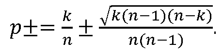
The deviation is maximum at k = n/2, which gives
Vfc(n - l)(n - fc)
n(n - 1)

The second derivative Bk n is therefore guaranteed to be nonnegative, and Bk nconvex, when p is at least
1/(2Vn - 1) away from the maximum at kin. It can be verified that the same sufficient condition applies for k = 0 and k = n.
For any p in the selected segment we know that Kh,d (p) remains constant and that | kin - p\ ³ 512 for any k .Kh,d (p).
To guarantee convexity we therefore require that
5/2 > l/(2y/n ^l
which simplifies to n ³ 1 + 1/d2.
[0099] The following statement regarding the error probability can also be verified. If we let Kn =

[00100] For example, if we denote by 8n = {(i,j) \ i,j £ [0 , n], i + j £ n } the complement of Kn. The error probability Pr(En \n, a) = lPr Kn\n, a ) is then obtained by summing fjj over (/, _/) er8n, where

Defining the diagonal sums k ^[0, n ] as
we can equivalently write
 easily seen that dk(a) = dk(n/2— a), and it therefore suffices to show the desired result for a ^[0, p/4]. As a first step, we bound the value of the main diagonal dn by 2 n


The right-most term, which accounts for the change in the binomial coefficient is less than or equal to 1 for / < n/2

when n is even, and for i £ (n + 1)/2 when n is odd. A similar argument applies for the transition from fij to fij- 1 for 1 < j £ {n + 1)/2, allowing us to bound the elements on the (n - 1)-diagonal dn -1 as follows: < (n - l)/2, otherwise.

[00101] FIGS.12A-12D show constructions for bounding (a,b) dn-1 based on dn, and (c,d) the sum of d/f for strided k, according to an embodiment of the present invention. As illustrated in FIGS. 12A and 12B, this approach uses the middle element of the main diagonal twice. Taking this into account, and effectively doing the same for all elements, we have
1-Px ! !-Py Py(l-Px)+Px(l~Py)
dn- 1— dn dn- (33)
Px Py PxPy
Combining (32) and (33) we have

As the third step, we derived bound on dk -2 based on dk . Consider any diagonal 2 £ k £ n, with 0 < / < k andy = k - /, then

Since k £ n, the multiplicative term k satisfies

It therefore follows that

The transition from diagonal k to k - 2 follows by summing over all elements / +j = k - 2, giving
dk 2 £ ( V -1 r Wc)( 1 - P Wy) dk = Tdki
PxPy
with t < 1, as shown in FIG. 13A. FIGS. 13A-13B are plots of key quantities used in verifying the statement with respect to the error probability, according to an embodiment of the present invention. As a fourth step we sum over the even and odd diagonals. Starting at k = n or k = n - 1 we have

For the sum of the diagonals, and hence that fjj over the error set set £n, it follows from equation (34) that

The desired result then follows from the observation that ( px + py - pxpy)/(px + py - 1) £ 2, as illustrated in FIG. 13B.
[00102] The descriptions of the various embodiments of the present invention have been presented for purposes of illustration, but are not intended to be exhaustive or limited to the embodiments disclosed. Many modifications and variations will be apparent to those of ordinary skill in the art without departing from the scope of the described embodiments. The terminology used herein was chosen to best explain the principles of the embodiments, the practical application or technical improvement over technologies found in the marketplace, or to enable others of ordinary skill in the art to understand the embodiments disclosed herein.
Claims
1. A method for determining a quantum phase induced by a unitary operator in a quantum device, the method comprising:
providing a plurality of quantum circuits connected in series, wherein an output of a first quantum circuit in the plurality of quantum circuits is an input of a second quantum circuit in the plurality of quantum circuits; and
determining a quantum phase induced by the unitary operator by performing a plurality of measurements of an output of each of the plurality of quantum circuits comprising performing a first measurement in the plurality of measurements of the quantum phase using the first quantum circuit in the plurality of quantum circuits and performing a second measurement in the plurality of measurements of the quantum phase using the second quantum circuit in the plurality of quantum circuits;
wherein a number of the plurality of quantum circuits used to determine the quantum phase depends on a number of the plurality of measurements needed to determine the quantum phase within a desired precision, wherein the number of the plurality of measurements is reduced for the desired precision by using a majority sampling method comprising:
performing a plurality of measurements for cosine and sine components of the quantum phase;
counting a number of measurements in a vertical axis for the sine component and counting a number of measurements in a horizontal axis for the cosine component; and
determining the quantum phase based on a majority of a number of 0 measurements and a number of 1 measurements of the sine component and the cosine component.
2. The method according to claim 1 , wherein the desired precision is at least 2 binary bits after the binary point.
3. The method according to either of the preceding claims, wherein determining the phase based on the majority of the number of 0 measurements and the number of 1 measurements of the sine component and the cosine component comprises determining a quantization of the quantum phase q(nx, ny) as a function of the number of measurements (ny) in the vertical axis for the sine component and the number of measurements (nx) in the horizontal axis for the cosine component.
4. The method according to claim 3, wherein the quantization of the quantum phase q(nx, ny) is equal to:
.00 if nx is greater than or equal to a maximum of ny and n-ny+1 ;
.01 if ny is greater than or equal to a maximum of nx+1 and n-nx;
.10 if n-nx is greater than or equal to a maximum of ny+1 and n-ny; and
.11 otherwise.
5. The method according to any of the preceding claims, wherein performing the first measurement or the second measurement comprises:
applying a first Hadamard gate to a first state of a first qubit to put the first qubit into a superposition of states; applying a phase shift gate to the superposition of states of the first qubit to apply a first phase to the first qubit;
applying a unitary operator (IIs) gate to a quantum state conditioned on the first qubit to apply a second phase to the quantum state;
applying a second Hadamard gate to the first qubit;
performing a measurement on the first qubit to determine probability values of measuring an output value of one based on input values of the first phase, the probability value depending on the first phase and the second phase; and
determining the second phase based on the probability values.
6. The method according to claim 1 , further comprising applying a NOT gate on the first qubit after applying the second Hadamard gate.
7. The method according to any of the preceding claims, wherein determining the second phase comprises selecting a value of the first phase equal to zero radian and -1/4 radian and estimating a sine and a cosine of the second phase based on probability values of obtaining an initial second phase at the selected value of the first phase.
8. The method according to claim 7, wherein applying the unitary operator (IIs) gate to the quantum state comprises applying the second phase multiplied by a factor that is proportional to 2 to the power j-1, wherein the second phase is expressed as a string of binary bits after the binary point and wherein j corresponds to incremental bit positions of binary bit values in the string of binary bits of the second phase.
9. The method according to claim 8, further comprising:
iteratively adding one bit to the string of binary bits of an initial second phase per step and shifting a previous bit string by one, and
repeating applying the first Hadamard gate to the first state of the first qubit; applying the phase shift gate to the superposition of states of the first qubit to apply the first phase to the first qubit; applying the unitary operator (IIs) gate to the quantum state conditioned on the first qubit to apply the second phase to the quantum state;
applying the second Hadamard gate on the first qubit;
performing the measurement on the first qubit to determine the probability values of measuring the output value of one based on the input values of the first phase, the probability value depending on the first phase and the second phase; and
determining an updated value of the second phase.
N mj
10. The method according to claim 9, further comprising:
choosing the first phase equal to the updated second phase divided by minus two to obtain an adjusted second phase that is a threshold value away from a horizontal axis;
determining a sign of a cosine of the adjusted second phase; and
setting a value of a last added binary bit in the string of binary bits of the updated second phase based on the determined sign of the cosine of the adjusted second phase.
11. The method according to claim 10, wherein if the sign of the cosine of the adjusted second phase is positive, setting the last added binary bit of the string of binary bits of the updated second phase to 0 and if the sign of the cosine of the adjusted second phase is negative, setting the last added binary bit of the string of binary bits of the updated second phase to 1.
12. The method according to claim 11 , wherein determining the updated value of the second phase comprises determining with a probability equal to at least substantially one a position of the updated second phase based on the sign of the cosine relative to right or left of a vertical axis when the adjusted second phase is at most p/4 from either 0 or p, or relative to a horizontal axis when the adjusted second phase is at most p/4 from either p/2 or 3p/2, or both.
13. A method of determining a quantum phase of quantum device, comprising:
performing a plurality of measurements for cosine and sine components of the quantum phase;
counting a number of measurements in a vertical axis for the sine component and counting a number of measurements in a horizontal axis for the cosine component; and
determining the quantum phase based on a majority of a number of 0 measurements and a number of 1 measurements of the sine component and the cosine component.
14. The method according to claim 13, wherein determining the phase based on the majority of the number of 0 measurements and the number of 1 measurements of sine component and the cosine component comprises determining a quantization of the quantum phase q(nx, ny) as a function of the number of measurements (nx) in the vertical axis for the sine component and the number of measurements (ny) in the horizontal axis for the cosine component.
15. The method according to claim 14, wherein the quantization of the quantum phase q(nx, ny) is equal to:
.00 if nx is greater than or equal to a maximum of ny and n-ny+1 ;
.01 if ny is greater than or equal to a maximum of nx+1 and n-nx;
.10 if n-nx is greater than or equal to a maximum of ny+1 and n-ny; and
.IT otherwise.
16. The method according to any of claims 13 to 15, further comprising:
iteratively adding one bit to the string of binary bits of an initial second phase per step and shifting a previous bit string by one, and
repeating applying the first Hadamard gate to the first state of the first qubit; applying the phase shift gate to the superposition of states of the first qubit to apply the first phase to the first qubit;
applying the unitary operator (IIs) gate to the quantum state conditioned on the first qubit to apply the second phase to the quantum state; applying the second Hadamard gate on the first qubit; performing the measurement on the first qubit to determine the probability values of measuring the output value of one based on the input values of the first phase, the probability value depending on the first phase and the second phase; and
determining an updated value of the second phase.
17. The method according to claim 16, further comprising:
choosing the first phase equal to the updated second phase divided by minus two to obtain an adjusted second phase that is a threshold value away from a horizontal axis;
determining a sign of a cosine of the adjusted second phase; and
setting a value of a last added binary bit in the string of binary bits of the updated second phase based on the determined sign of the cosine of the adjusted second phase.
18. The method according to claim 17, wherein if the sign of the cosine of the adjusted second phase is positive, setting the last added binary bit of the string of binary bits of the updated second phase to 0 and if the sign of the cosine of the adjusted second phase is negative, setting the last added binary bit of the string of binary bits of the updated second phase to 1.
19. The method according to claim 18, wherein determining the updated value of the second phase comprises determining with a probability equal to at least substantially one a position of the updated second phase based on the sign of the cosine relative to right or left of a vertical axis when the adjusted second phase is at most p/4 from either 0 or p, or relative to a horizontal axis when the adjusted second phase is at most p/4 from either p/2 or 3p/2, or both.
20. A quantum device comprising a plurality of quantum circuits for determining the quantum phase, comprising: a plurality of quantum circuits connected in series, wherein an output of a first quantum circuit in the plurality of quantum circuits is an input of a second quantum circuit in the plurality of quantum circuits, wherein the plurality of
quantum circuits are configured and arranged to determine a quantum phase induced by a unitary operator in the quantum device by performing a plurality of measurements of an output of each of the plurality of quantum circuits comprising performing a first measurement in the plurality of measurements of the quantum phase using the first quantum circuit in the plurality of quantum circuits and performing a second measurement in the plurality of measurements of the quantum phase using the second quantum circuit in the plurality of quantum circuits;
wherein a number of the plurality of quantum circuits used to determine the quantum phase depends on a number of the plurality of measurements needed to determine the quantum phase within a desired precision, wherein a number of the plurality of measurements is reduced for the desired precision by using a majority sampling method comprising:
performing a plurality of measurements for cosine and sine components of the quantum phase;
counting a number of measurements in a vertical axis for the sine component and counting a number of measurements in a horizontal axis for the cosine component; and
determining the quantum phase based on a majority of a number of 0 measurements and a number of 1 measurements of the sine component and the cosine component.
21. The quantum device according to claim 20, wherein the first quantum circuit or the second quantum circuit or both comprises:
a first Hadamard gate configured to apply to a first state of a first qubit to put the first qubit into a superposition of states;
a phase shift gate configured to apply to the superposition of states of the first qubit a first phase;
a unitary operator (IIs) gate configured to apply to a quantum state conditioned on the first qubit a second phase;
a second Hadamard gate configured to apply a second quantum phase to the first qubit;
a measurement component configured to perform a measurement on the first qubit to determine probability values of measuring an output value of one based on input values of the first phase, the probability value depending on the first phase and the second phase.
Applications Claiming Priority (2)
| Application Number | Priority Date | Filing Date | Title |
|---|---|---|---|
| US16/281,851 US11176478B2 (en) | 2019-02-21 | 2019-02-21 | Method for estimating a quantum phase |
| US16/281,851 | 2019-02-21 |
Publications (1)
| Publication Number | Publication Date |
|---|---|
| WO2020169749A1 true WO2020169749A1 (en) | 2020-08-27 |
Family
ID=69645991
Family Applications (1)
| Application Number | Title | Priority Date | Filing Date |
|---|---|---|---|
| PCT/EP2020/054513 Ceased WO2020169749A1 (en) | 2019-02-21 | 2020-02-20 | Method for estimating a quantum phase |
Country Status (2)
| Country | Link |
|---|---|
| US (1) | US11176478B2 (en) |
| WO (1) | WO2020169749A1 (en) |
Families Citing this family (5)
| Publication number | Priority date | Publication date | Assignee | Title |
|---|---|---|---|---|
| US12475393B2 (en) * | 2019-08-12 | 2025-11-18 | International Business Machines Corporation | Qubit sensory representation |
| US11121878B2 (en) * | 2019-10-11 | 2021-09-14 | Accenture Global Solutions Limited | Authentication using key distribution through segmented quantum computing environments |
| US11487504B2 (en) | 2019-10-11 | 2022-11-01 | Accenture Global Solutions Limited | Generating quantum representations of hexadecimal data |
| CN115511094B (en) * | 2021-06-23 | 2023-06-02 | 合肥本源量子计算科技有限责任公司 | Quantum circuit execution result determining method and device and quantum computer operating system |
| CN115694627A (en) * | 2021-07-22 | 2023-02-03 | 北京中创为南京量子通信技术有限公司 | Quantum entanglement source fidelity measurement system and method |
Citations (1)
| Publication number | Priority date | Publication date | Assignee | Title |
|---|---|---|---|---|
| US20110138344A1 (en) * | 2009-12-08 | 2011-06-09 | University Of Seoul Industry Cooperation Foundation | Quantum karnaugh map |
Family Cites Families (3)
| Publication number | Priority date | Publication date | Assignee | Title |
|---|---|---|---|---|
| US9275011B2 (en) * | 2013-03-27 | 2016-03-01 | Microsoft Technology Licensing, Llc | Fast quantum and classical phase estimation |
| CN109074518B (en) | 2015-12-30 | 2022-09-20 | 谷歌有限责任公司 | Quantum phase estimation of multiple eigenvalues |
| CN109983481B (en) | 2016-09-26 | 2023-08-15 | D-波系统公司 | System, method and apparatus for sampling from sampling server |
-
2019
- 2019-02-21 US US16/281,851 patent/US11176478B2/en active Active
-
2020
- 2020-02-20 WO PCT/EP2020/054513 patent/WO2020169749A1/en not_active Ceased
Patent Citations (1)
| Publication number | Priority date | Publication date | Assignee | Title |
|---|---|---|---|---|
| US20110138344A1 (en) * | 2009-12-08 | 2011-06-09 | University Of Seoul Industry Cooperation Foundation | Quantum karnaugh map |
Non-Patent Citations (4)
| Title |
|---|
| DAMIAN S STEIGER: "Software and Algorithms for Quantum Computing", 1 January 2018 (2018-01-01), pages 1 - 111, XP055695781, Retrieved from the Internet <URL:https://www.research-collection.ethz.ch/bitstream/handle/20.500.11850/322770/thesis.pdf> [retrieved on 20200515], DOI: 10.3929/ethz-b-000322770 * |
| EWOUT VAN DEN BERG: "Practical sampling schemes for quantum phase estimation", ARXIV.ORG, CORNELL UNIVERSITY LIBRARY, 201 OLIN LIBRARY CORNELL UNIVERSITY ITHACA, NY 14853, 28 February 2019 (2019-02-28), XP081034922 * |
| KRYSTA M SVORE ET AL: "Faster Phase estimation", INTERNET CITATION, 2 April 2013 (2013-04-02), pages 1 - 14, XP002736091, Retrieved from the Internet <URL:http://arxiv.org/pdf/1304.0741.pdf> [retrieved on 20150217] * |
| WOOTTERS MARY ET AL: "Lower bounds for quantized matrix completion", 2013 IEEE INTERNATIONAL SYMPOSIUM ON INFORMATION THEORY, IEEE, 7 July 2013 (2013-07-07), pages 296 - 300, XP032497176, ISSN: 2157-8095, [retrieved on 20131003], DOI: 10.1109/ISIT.2013.6620235 * |
Also Published As
| Publication number | Publication date |
|---|---|
| US20200272928A1 (en) | 2020-08-27 |
| US11176478B2 (en) | 2021-11-16 |
Similar Documents
| Publication | Publication Date | Title |
|---|---|---|
| WO2020169749A1 (en) | Method for estimating a quantum phase | |
| Evans et al. | A proof of the Gamma test | |
| Elfverson et al. | A multilevel Monte Carlo method for computing failure probabilities | |
| Mommer et al. | A goal-oriented adaptive finite element method with convergence rates | |
| Kalantari | A characterization theorem and an algorithm for a convex hull problem | |
| Rempe-Gillen et al. | Non-autonomous conformal iterated function systems and Moran-set constructions | |
| Barth et al. | A study of elliptic partial differential equations with jump diffusion coefficients | |
| CN112884154B (en) | Quantum state resolution methods, devices and systems, quantum measurement and control systems and computers | |
| Schuëller et al. | A comparative study of reliability estimation procedures for high dimensions | |
| Schindler et al. | Generic power attacks on RSA with CRT and exponent blinding: new results | |
| Henning et al. | On discrete ground states of rotating Bose–Einstein condensates | |
| Friedrich et al. | Cliques in high-dimensional geometric inhomogeneous random graphs | |
| De Philippis et al. | Closed geodesics on reversible Finsler 2-spheres | |
| Olver et al. | Numerical solution of Riemann–Hilbert problems: random matrix theory and orthogonal polynomials | |
| Kato et al. | Existence for doubly nonlinear fractional p-Laplacian equations | |
| Radinović et al. | Alcock–Paczyński effect on void-finding: implications for void-galaxy cross-correlation modelling | |
| Mehrmann et al. | An SVD approach to identifying metastable states of Markov chains | |
| van den Berg | Iterative quantum phase estimation with optimized sample complexity | |
| Busch et al. | Sharp uncertainty relations for number and angle | |
| Nicaise | A posteriori error estimations of some cell centered finite volume methods for diffusion-convection-reaction problems | |
| Berthé et al. | Dynamics of Ostrowski skew-product: 1. Limit laws and Hausdorff dimensions | |
| den Boer | An efficient algorithm for computing nearest medium approximations to an arbitrary anisotropic stiffness tensor | |
| Poláčik | Estimates of solutions and asymptotic symmetry for parabolic equations on bounded domains | |
| Berg | Practical sampling schemes for quantum phase estimation | |
| CN103984519B (en) | Method and apparatus for examining digital multiplier |
Legal Events
| Date | Code | Title | Description |
|---|---|---|---|
| 121 | Ep: the epo has been informed by wipo that ep was designated in this application |
Ref document number: 20706477 Country of ref document: EP Kind code of ref document: A1 |
|
| NENP | Non-entry into the national phase |
Ref country code: DE |
|
| 122 | Ep: pct application non-entry in european phase |
Ref document number: 20706477 Country of ref document: EP Kind code of ref document: A1 |