WO2020166618A1 - 通信制御方法、ユーザ装置、及び基地局 - Google Patents
通信制御方法、ユーザ装置、及び基地局 Download PDFInfo
- Publication number
- WO2020166618A1 WO2020166618A1 PCT/JP2020/005381 JP2020005381W WO2020166618A1 WO 2020166618 A1 WO2020166618 A1 WO 2020166618A1 JP 2020005381 W JP2020005381 W JP 2020005381W WO 2020166618 A1 WO2020166618 A1 WO 2020166618A1
- Authority
- WO
- WIPO (PCT)
- Prior art keywords
- rrc
- control signal
- data
- indicator
- base station
- Prior art date
- Legal status (The legal status is an assumption and is not a legal conclusion. Google has not performed a legal analysis and makes no representation as to the accuracy of the status listed.)
- Ceased
Links
Images





Classifications
-
- H—ELECTRICITY
- H04—ELECTRIC COMMUNICATION TECHNIQUE
- H04W—WIRELESS COMMUNICATION NETWORKS
- H04W76/00—Connection management
- H04W76/30—Connection release
- H04W76/38—Connection release triggered by timers
-
- H—ELECTRICITY
- H04—ELECTRIC COMMUNICATION TECHNIQUE
- H04W—WIRELESS COMMUNICATION NETWORKS
- H04W76/00—Connection management
- H04W76/20—Manipulation of established connections
- H04W76/27—Transitions between radio resource control [RRC] states
-
- H—ELECTRICITY
- H04—ELECTRIC COMMUNICATION TECHNIQUE
- H04W—WIRELESS COMMUNICATION NETWORKS
- H04W76/00—Connection management
- H04W76/20—Manipulation of established connections
Definitions
- the present disclosure relates to a communication control method, a user equipment, and a base station in a mobile communication system.
- RRC connected mode RRC inactive mode
- RRC idle mode RRC (Radio Resource Control) modes of user equipment.
- RRC connected mode and RRC inactive mode are modes in which the RRC connection of the user equipment is established.
- the RRC inactive mode is a mode in which the established RRC connection is suspended.
- the RRC idle mode is a mode in which the RRC connection of the user equipment is not established.
- the user equipment in the RRC idle mode or the RRC inactive mode only needs to monitor the downlink control channel at periodic paging occasions, and thus the consumption of the user equipment is small.
- the user equipment in the RRC connected mode needs to frequently monitor at least the downlink control channel in order to perform data communication, and the power consumption of the user equipment is large.
- the communication control method is a method in a mobile communication system.
- a user apparatus in an RRC (Radio Resource Control) connected mode determines that there is no data with which the user apparatus communicates with a base station, the state in which the data does not exist is maintained. Predicting a time, and the user equipment sending a control signal to the base station, the control signal including an indicator for identifying the predicted duration.
- RRC Radio Resource Control
- the user device is a device in a mobile communication system.
- the user equipment determines that there is no data to communicate with the base station, the user equipment controls to predict the duration in which the data equipment does not exist.
- a transmitter that transmits a control signal including an indicator for specifying the predicted duration to the base station.
- the base station is a device in a mobile communication system.
- the base station includes an indicator for specifying from a user equipment in an RRC (Radio Resource Control) connected mode a duration for which the state in which there is no data for the user equipment to communicate with the base station is maintained.
- a receiver that receives a control signal, and a controller that determines whether to transition the user apparatus to the RRC idle mode or the RRC inactive mode based on the information included in the control signal.
- RRC Radio Resource Control
- the mobile communication system according to one embodiment is a 3GPP 5G system
- LTE Long Term Evolution
- FIG. 1 is a diagram showing a configuration of a mobile communication system according to an embodiment.
- the mobile communication system includes a user apparatus (UE: User Equipment) 100, a 5G radio access network (NG-RAN: Next Generation Radio Access Network) 10, and a 5G core network (5GC: 5G). Core Network) 20 and.
- UE User Equipment
- NG-RAN Next Generation Radio Access Network
- 5G core network 5G core network
- the UE 100 is a movable device.
- the UE 100 may be any device as long as it is a device used by a user.
- the UE 100 is a mobile phone terminal (including a smartphone), a tablet terminal, a notebook PC, a communication module (including a communication card or a chipset), a sensor or a device provided in the sensor, a vehicle or a device provided in the vehicle (Vehicle UE). ), or a device or an apparatus (Aerial UE) provided on the device.
- the NG-RAN 10 includes a base station (called “gNB” in the 5G system) 200.
- the gNB 200 is sometimes called an NG-RAN node.
- the gNBs 200 are connected to each other via an Xn interface which is an interface between base stations.
- the gNB 200 manages one or a plurality of cells.
- the gNB 200 performs wireless communication with the UE 100 that has established a connection with its own cell.
- the gNB 200 has a radio resource management (RRM) function, a user data (hereinafter simply referred to as “data”) routing function, and/or a measurement control function for mobility control/scheduling.
- RRM radio resource management
- Cell is used as a term indicating a minimum unit of a wireless communication area.
- the “cell” is also used as a term indicating a function or resource for performing wireless communication with the UE 100.
- One cell belongs to one carrier frequency.
- the gNB may be connected to EPC (Evolved Packet Core), which is the LTE core network, or the LTE base station may be connected to 5GC. Also, the LTE base station and the gNB may be connected via an inter-base station interface.
- EPC Evolved Packet Core
- the 5GC 20 includes an AMF (Access and Mobility Management Function) and an UPF (User Plane Function) 300.
- the AMF performs various mobility controls for the UE 100.
- the AMF manages information on the area in which the UE 100 is located by communicating with the UE 100 using NAS (Non-Access Stratum) signaling.
- the UPF controls data transfer.
- the AMF and UPF are connected to the gNB 200 via the NG interface which is an interface between the base station and the core network.
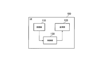
- FIG. 2 is a diagram showing the configuration of the UE 100 (user device).
- the UE 100 includes a reception unit 110, a transmission unit 120, and a control unit 130.
- the receiving unit 110 performs various types of reception under the control of the control unit 130.
- the receiver 110 includes an antenna and a receiver.
- the receiver converts the radio signal received by the antenna into a baseband signal (received signal) and outputs the baseband signal to the control unit 130.
- the transmission unit 120 performs various types of transmission under the control of the control unit 130.
- the transmitter 120 includes an antenna and a transmitter.
- the transmitter converts the baseband signal (transmission signal) output by the control unit 130 into a radio signal and transmits the radio signal from the antenna.
- the control unit 130 performs various controls in the UE 100.
- the control unit 130 includes at least one processor and at least one memory electrically connected to the processor.
- the memory stores a program executed by the processor and information used for processing by the processor.
- the processor may include a baseband processor and a CPU (Central Processing Unit).
- the baseband processor performs modulation/demodulation and coding/decoding of the baseband signal.
- the CPU executes programs stored in the memory to perform various kinds of processing.
- FIG. 3 is a diagram showing a configuration of the gNB 200 (base station).
- the gNB 200 includes a transmission unit 210, a reception unit 220, a control unit 230, and a backhaul communication unit 240.
- the transmission unit 210 performs various types of transmission under the control of the control unit 230.
- the transmitter 210 includes an antenna and a transmitter.
- the transmitter converts the baseband signal (transmission signal) output by the control unit 230 into a radio signal and transmits the radio signal from the antenna.
- the receiving unit 220 performs various types of reception under the control of the control unit 230.
- the receiver 220 includes an antenna and a receiver.
- the receiver converts the radio signal received by the antenna into a baseband signal (received signal) and outputs the baseband signal to the control unit 230.
- the control unit 230 performs various controls in the gNB 200.
- the control unit 230 includes at least one processor and at least one memory electrically connected to the processor.
- the memory stores a program executed by the processor and information used for processing by the processor.
- the processor may include a baseband processor and a CPU.
- the baseband processor performs modulation/demodulation and coding/decoding of the baseband signal.
- the CPU executes programs stored in the memory to perform various kinds of processing.
- the backhaul communication unit 240 is connected to an adjacent base station via an interface between base stations.
- the backhaul communication unit 240 is connected to the AMF/UPF 300 via a base station-core network interface.
- the gNB may be composed of a CU (Central Unit) and a DU (Distributed Unit) (that is, functionally divided), and both units may be connected by an F1 interface.
- FIG. 4 is a diagram showing a configuration of a protocol stack of a wireless interface of a user plane that handles data.
- the radio interface protocol of the user plane includes a physical (PHY) layer, a MAC (Medium Access Control) layer, an RLC (Radio Link Control) layer, and a PDCP (Packet Data Convergence Protocol) layer. It has a SDAP (Service Data Adaptation Protocol) layer.
- PHY physical
- MAC Medium Access Control
- RLC Radio Link Control
- PDCP Packet Data Convergence Protocol
- SDAP Service Data Adaptation Protocol
- PHY layer performs encoding/decoding, modulation/demodulation, antenna mapping/demapping, and resource mapping/demapping. Data and control information are transmitted via a physical channel between the PHY layer of the UE 100 and the PHY layer of the gNB 200.
- the MAC layer performs data priority control, retransmission processing by hybrid ARQ (HARQ), random access procedure, etc. Data and control information are transmitted via the transport channel between the MAC layer of the UE 100 and the MAC layer of the gNB 200.
- the MAC layer of gNB200 includes a scheduler. The scheduler determines uplink and downlink transport formats (transport block size, modulation/coding method (MCS)) and resource blocks allocated to the UE 100.
- MCS modulation/coding method
- the RLC layer uses the functions of the MAC layer and PHY layer to transmit data to the RLC layer on the receiving side. Data and control information are transmitted via the logical channel between the RLC layer of the UE 100 and the RLC layer of the gNB 200.
- the PDCP layer performs header compression/decompression and encryption/decryption.
- the SDAP layer maps the IP flow, which is the unit in which the core network performs QoS control, and the radio bearer, which is the unit in which AS (Access Stratum) performs QoS control.
- SDAP may be omitted.
- FIG. 5 is a diagram showing a configuration of a protocol stack of a radio interface of a control plane that handles signaling (control signal).
- the protocol stack of the radio interface of the control plane has an RRC (Radio Resource Control) layer and a NAS (Non-Access Stratum) layer instead of the SDAP layer shown in FIG.
- RRC signaling for various settings is transmitted between the RRC layer of the UE 100 and the RRC layer of the gNB 200.
- the RRC layer controls logical channels, transport channels and physical channels according to establishment, re-establishment and release of radio bearers.
- RRC connection connection between the RRC of the UE 100 and the RRC of the gNB 200
- the UE 100 is in the RRC connected mode.
- RRC connection no connection between the RRC of the UE 100 and the RRC of the gNB 200
- the UE 100 is in the RRC idle mode.
- the RRC connection is suspended (suspended), the UE 100 is in the RRC inactive mode.
- the NAS layer which is located above the RRC layer, performs session management, mobility management, etc.
- NAS signaling is transmitted between the NAS layer of the UE 100 and the NAS layer of the AMF 300.
- the UE 100 has an application layer and the like in addition to the wireless interface protocol.
- the RRC connected mode and the RRC inactive mode are modes in which the RRC connection of the UE 100 is established.
- the RRC inactive mode is a mode in which the established RRC connection is suspended.
- the RRC idle mode is a mode in which the RRC connection of the UE 100 is not established.
- the UE 100 in the RRC idle mode or the RRC inactive mode only needs to monitor the downlink control channel only at periodic paging occasions, and thus the UE 100 consumes less power.
- the UE 100 in the RRC connected mode needs to frequently monitor at least the downlink control channel in order to perform data communication, and the UE 100 consumes a large amount of power.
- FIG. 6 is a diagram showing an operation of the mobile communication system according to the embodiment.
- step S101 the UE 100 is in the RRC connected mode in the cell of the gNB 200.
- the UE 100 in the RRC connected mode performs data communication with the gNB 200.
- the UE 100 transmits uplink data to the gNB 200 via PUSCH (Physical Uplink Shared Channel), and receives downlink data from the gNB 200 via PDSCH (Physical Downlink Shared Channel).
- PUSCH Physical Uplink Shared Channel
- PDSCH Physical Downlink Shared Channel
- the gNB 200 sets a threshold for the UE 100.
- the threshold value defines a condition for transmitting an indicator indicating that there is no data for communicating with the gNB 200 from the UE 100 to the gNB 200.
- Such an indicator is sometimes called RAI (Release Assistance Indicator).
- the setting in step S102 may be made by the RRC message transmitted/received in the RRC layer.
- the RRC message may be a dedicated message that is unicast-transmitted for each UE or a common message (system information block) that is broadcast-transmitted to multiple UEs in a cell.
- the gNB 200 may set a plurality of thresholds for the UE 100. For example, gNB200 transmits the RRC message containing a 1st threshold value and a 2nd threshold value larger than a 1st threshold value to UE100.
- the first threshold indicates a time length of about 10 seconds, for example, and the second threshold indicates a time length of about 1 minute, for example.
- the threshold value is not limited to two and may be three or more.
- the UE 100 Upon receiving the RRC message including a plurality of thresholds from the gNB 200, the UE 100 stores the plurality of thresholds included in the received RRC message.
- the gNB 200 may set the UE 100 to enable the transmission of the indicator (RAI) in addition to setting the threshold value.
- the gNB 200 may implicitly set the UE 100 to enable the transmission of the indicator. For example, the UE 100 may regard that the threshold value is set, and thus the validation of the transmission of the indicator is set.
- the gNB 200 instead of the gNB 200 setting a plurality of thresholds in the UE 100, at least one of the plurality of thresholds may be preset in the UE 100.
- the threshold defined by the communication standard may be set in the UE 100 in advance when the UE 100 is shipped.
- step S103 the UE 100 determines that the data (uplink data and/or downlink data) for communicating with the gNB 200 is no longer present. For example, the UE 100 detects that the buffer for temporarily storing the uplink data to be transmitted to the gNB 200 has become empty. The UE 100 may determine that there is no data to communicate with the gNB 200 based on the information obtained from the application layer.
- the UE 100 predicts a duration (hereinafter, referred to as “communication suspension duration”) in which a state in which data (uplink data and/or downlink data) communicating with the gNB 200 does not exist is maintained. For example, the UE 100 predicts the communication suspension duration based on the information obtained from the application layer. The UE 100 acquires from the application information indicating when the next data to be transmitted to the network by the application occurs and/or information indicating when the next data to be received by the application from the network occurs from the application, and based on the obtained information. The communication stop duration may be predicted. The UE 100 may statistically learn the past communication suspension duration and predict the communication suspension duration based on the learning result.
- communication suspension duration a duration in which a state in which data (uplink data and/or downlink data) communicating with the gNB 200 does not exist is maintained. For example, the UE 100 predicts the communication suspension duration based on the information obtained from the application layer. The UE 100 acquires from the application information indicating when the next data to be transmitted
- step S105 the UE 100 compares the communication suspension duration predicted in step S104 with a plurality of thresholds.
- step S106 the UE 100 transmits a control signal including an indicator to the gNB 200 based on the result of comparison between the communication suspension duration and a plurality of thresholds.
- the gNB 200 receives the control signal including the indicator from the UE 100.
- the control signal is a buffer status report transmitted/received in the MAC layer.
- the buffer status report is a type of MAC CE (Control Element).
- the indicator may be a buffer size value included in the buffer status report.
- the UE 100 transmits to the gNB 200 a buffer status report including a buffer size value according to the predicted duration.
- control signal is an RRC message transmitted/received in the RRC layer.
- the indicator may be an information element (IE) included in the RRC message.
- the UE 100 transmits to the gNB 200 an RRC message including an information element according to the predicted duration.
- FIG. 7 is a diagram showing a specific example of steps S105 and S106 of FIG.
- FIG. 7 illustrates an example in which the UE 100 is set with the first threshold and the second threshold larger than the first threshold.
- the UE 100 when the communication suspension duration predicted in step S104 is less than the first threshold value, the UE 100 does not transmit the control signal including the indicator (RAI) to the gNB 200. If the suspension of the data communication is temporary and the data communication is resumed in the near future, the UE 100 preferably maintains the RRC connected mode. Therefore, when the communication suspension duration predicted in step S104 is less than the first threshold, the UE 100 does not transmit the indicator (RAI) to the gNB 200.
- the UE 100 sets the first indicator as the indicator (RAI).
- the control signal containing it is transmitted to gNB200.
- the UE 100 sets a second indicator different from the first indicator as the indicator (RAI).
- the control signal containing it is transmitted to gNB200.
- a multi-step indicator is introduced so that the gNB 200 can grasp the length of the communication suspension duration.
- the buffer size values to be used as the first indicator and the second indicator may be set (designated) from the gNB 200 to the UE 100. This setting may be made in step S102.
- the first indicator may be “RAI_LOW” and the second indicator may be “RAI_HIGH”.
- the first indicator may be “the first threshold value has been satisfied” and the second indicator may be “the second threshold value has been satisfied”.
- the gNB 200 determines, based on the indicator included in the control signal received from the UE 100, whether to cause the UE 100 to transition to the RRC idle mode or the RRC inactive mode. .. In one embodiment, when the indicator included in the control signal received from the UE 100 is the first indicator, the gNB 200 determines to transition the UE 100 to the RRC inactive mode. On the other hand, when the indicator included in the control signal received from the UE 100 is the second indicator, the gNB 200 determines to transition the UE 100 to the RRC idle mode.
- step S108 the gNB 200 transmits an RRC release message, which is a type of dedicated RRC message, to the UE 100 based on the determination result in step S107.
- the gNB 200 determines to transition the UE 100 to the RRC inactive mode, the gNB 200 includes the RRC inactive mode setting information (SuspendConfig) in the RRC release message.
- Suspend Config includes a ran-PagingCycle that is a DRX (discontinuous reception) cycle for the RRC inactive mode and a fullI-RNTI or a shortI-RNTI that is an identifier assigned to the UE 100 for the RRC inactive mode.
- the gNB 200 does not include SuspendConfig in the RRC release message when determining that the UE 100 is transited to the RRC idle mode.
- step S109 the UE 100 transitions to the RRC idle mode or the RRC inactive mode based on the RRC release message received from the gNB 200. Specifically, the UE 100 transitions to the RRC inactive mode if the RRC release message includes SuspendConfig, and transitions to the RRC idle mode if the RRC release message does not include SuspendConfig.
- the gNB 200 can recognize the length of the communication suspension duration, and accordingly, the UE 100 sets an appropriate mode among the RRC idle mode and the RRC inactive mode according to the communication suspension duration. it can.
- the value indicating the communication suspension duration predicted in step S104 may be included in the RRC message as an indicator.
- the indicator indicating the value indicating the communication stop duration time may be selected from among the predefined candidates such as 1s, 5s, 10s, 15s, 30s, 60s,..., 1h,..., 1day.
- the value itself of the predicted communication suspension duration may be included in the RRC message as an indicator, without being limited to the case of selecting from among the candidates defined in advance.
- the threshold setting (step S102) and the threshold comparison (step S105) may be unnecessary.
- one threshold may be set in the UE 100 from the gNB 200 as the transmission trigger condition of the RRC message including such an indicator (step S102).
- a new MAC CE may be introduced, and the MAC CE including the indicator indicating the communication suspension duration may be transmitted from the UE 100 to the gNB 200 (step S106).
- the UE 100 determines that there is no data to communicate with the gNB 200 (step S103), and then transmits a control signal including the indicator (RAI) to the gNB 200 (step S106). Was there.
- the UE 100 may determine that the data communicating with the gNB 200 will not exist in the future when the data communicating with the gNB 200 exists.
- the control signal including the indicator (RAI) may be transmitted to the gNB 200 before the data for actually communicating with the gNB 200 is not present (step S106).
- FIG. 8 is a diagram showing an operation of the mobile communication system according to the second modification of the embodiment.
- differences from this operation will be mainly described on the premise of the operation of the above-described embodiment, but the operation of Modification 1 described above may be premised.
- steps S201 and S202 are the same as steps S101 and S102 of FIG.
- the UE 100 predicts a timing at which data for communicating with the gNB 200 will not exist in the future (hereinafter referred to as “communication stop start timing”).
- the UE 100 may predict the communication stop start timing based on the amount of uplink data in the buffer of the UE 100, or may predict the communication stop start timing based on information obtained from the application layer.
- the communication stop start timing may be the time when the transmission of the data currently stored in the buffer (or the data notified to the gNB 200 in the buffer status report) is completed.
- step S204 the UE 100 predicts the communication suspension duration as in the above-described embodiment.
- step S205 the UE 100 compares the communication suspension duration predicted in step S104 with a plurality of thresholds.
- the UE 100 transmits a control signal including an indicator to the gNB 200 based on the result of comparison between the communication suspension duration and a plurality of thresholds.
- the UE 100 further includes information for identifying the communication stop start timing predicted in step S203 in the control signal.
- the information for specifying the communication stop start timing may be information expressed in absolute time or information expressed in relative time with reference to the transmission timing of the control signal.
- the information for specifying the communication stop start timing may be information represented by the remaining data amount of the data (uplink data and/or downlink data) communicated with the gNB 200.
- step S207 the UE 100 enters a state in which there is no data (uplink data and/or downlink data) communicating with the gNB 200 at the communication stop start timing.
- step S208 the gNB 200 determines whether to shift the UE 100 to the RRC idle mode or the RRC inactive mode, as in the above-described embodiment.
- step S209 the gNB 200 transmits an RRC release message to the UE 100 based on the communication stop start timing notified from the UE 100. For example, the gNB 200 transmits the RRC release message to the UE 100 at or immediately after the communication stop start timing.
- Step S210 is the same as step S109 in FIG.
- the bearers are not distinguished under the assumption that a plurality of bearers are set in the UE 100, but the gNB 200 may set the threshold for each bearer of the UE 100.
- the gNB 200 may set the threshold value in the UE 100 by associating the threshold value with the bearer identifier.
- the UE 100 may notify the gNB 200 of the indicator (RAI) in association with the bearer identifier in addition to the threshold information.
- RAI indicator
- the gNB 200 can identify a bearer for which communication is not performed for a certain period, by the RAI. Therefore, the gNB 200 releases only the setting of the specified bearer while maintaining the UE 100 in the RRC connected mode, performs the communication setting suitable for the bearer other than the bearer, and handovers the UE 100 to the optimum cell or frequency. It can be done.
- the gNB 200 releases the setting of carrier aggregation from the UE 100 or releases the UE from a high frequency such as 3.5 GHz to a low frequency of 800 MHz by releasing a bearer for high-speed communication such as video reception. be able to. Therefore, the power consumption of the UE 100 can be reduced.
- the 5G system (NR) was mainly described, but the operation according to the embodiment may be applied to LTE.
- the UE 100 may be a UE for machine type communication or IoT.
- a program that causes a computer to execute each process performed by the UE 100 or the gNB 200 may be provided.
- the program may be recorded in a computer-readable medium.
- a computer readable medium can be used to install the program on a computer.
- the computer-readable medium in which the program is recorded may be a non-transitory recording medium.
- the non-transitory recording medium is not particularly limited, but may be a recording medium such as a CD-ROM or a DVD-ROM.
- a circuit that executes each process performed by the UE 100 or the gNB 200 may be integrated, and at least a part of the UE 100 or the gNB 200 may be configured as a semiconductor integrated circuit (chip set, SoC).
- Proposal 1 RAN2 should study a solution that minimizes the duration of unnecessarily keeping the UE in RRC connected mode.
- gNB is expected to send RRC release as soon as possible after DL/UL data transmission is completed. However, immediately after RRC release, if additional data arrives, the UE needs to re-transition to RRC connected mode. Such frequent back and forth transitions of the RRC state are undesirable. Therefore, in order to better understand when to send an RRC Release, the gNB may need to know if DL/UL will occur in the near future.
- RAI Release Assistance Indication
- NR has additional features that are not available in LTE (eg, inactive state)
- some extension to existing RAIs may be required. Details can be discussed later.
- Proposal 2 RAN2 should agree to adopt the concept of RAI (Release Assistance Indication) as a baseline, and the details and possibilities of extension should be further studied.
- RAI Release Assistance Indication
- the current specification is that the UE delays the process of transitioning to Idle/Inactive mode by 60 ms after receiving the RRC Release message, or optionally acknowledges messages from lower layers. Changes to idle mode/inactive mode. Therefore, the 60 ms delay in LTE allows for L2 acknowledgments, ie RLC status reports and HARQ ACKs. Since the processing delay of this RRC connection release continues from Rel-8, it should be reconsidered whether it is applicable to NR. For example, the extended RRC release message may instruct the UE to transition to the idle mode/inactive mode only when the data transmission ends (eg, conditional RRC release). Details and other solutions should be studied further.
- Observation 1 Currently, the UE does not transition to the idle mode immediately after receiving the RRC release. That is, wait 60 milliseconds or wait for an acknowledgment from the lower layer.
- Proposal 3 RAN2 should consider a solution that minimizes the delay when receiving an RRC release.
Landscapes
- Engineering & Computer Science (AREA)
- Computer Networks & Wireless Communication (AREA)
- Signal Processing (AREA)
- Mobile Radio Communication Systems (AREA)
- Finishing Walls (AREA)
Abstract
一実施形態に係る通信制御方法は、移動通信システムにおける方法である。前記通信制御方法は、RRCコネクティッドモードにあるユーザ装置が、前記ユーザ装置が基地局と通信するデータが存在しないと判定する場合、前記データが存在しない状態が持続される持続時間を予測することと、前記ユーザ装置が、前記予測した持続時間を特定するための指示子を含む制御信号を前記基地局に送信することとを含む。
Description
本開示は、移動通信システムにおける通信制御方法、ユーザ装置、及び基地局に関する。
従来、移動通信システムの標準化プロジェクトである3GPP(3rd Generation Partnership Project)において、ユーザ装置のRRC(Radio Resource Control)のモードとして、RRCコネクティッドモード、RRCインアクティブモード、及びRRCアイドルモードが規定されている。
RRCコネクティッドモード及びRRCインアクティブモードはユーザ装置のRRC接続が確立されているモードである。但し、RRCインアクティブモードは、確立されたRRC接続が中断(サスペンド)されているモードである。RRCアイドルモードは、ユーザ装置のRRC接続が確立されていないモードである。
RRCアイドルモード又はRRCインアクティブモードにあるユーザ装置は、周期的なページング機会においてのみ下りリンク制御チャネルを監視すればよいため、ユーザ装置の消費が小さい。一方、RRCコネクティッドモードにあるユーザ装置は、データ通信を行うために少なくとも下りリンク制御チャネルの頻繁な監視を行う必要があり、ユーザ装置の消費電力が大きい。
よって、ユーザ装置の消費電力を削減するために、ユーザ装置がRRCコネクティッドモードからRRCアイドルモード又はRRCインアクティブモードに適切に遷移可能とする技術の実現が望まれている。
一実施形態に係る通信制御方法は、移動通信システムにおける方法である。前記通信制御方法は、RRC(Radio Resource Control)コネクティッドモードにあるユーザ装置が、前記ユーザ装置が基地局と通信するデータが存在しないと判定する場合、前記データが存在しない状態が持続される持続時間を予測することと、前記ユーザ装置が、前記予測した持続時間を特定するための指示子を含む制御信号を前記基地局に送信することとを含む。
一実施形態に係るユーザ装置は、移動通信システムにおける装置である。前記ユーザ装置は、RRC(Radio Resource Control)コネクティッドモードにおいて、前記ユーザ装置が基地局と通信するデータが存在しないと判定する場合、前記データが存在しない状態が持続される持続時間を予測する制御部と、前記予測した持続時間を特定するための指示子を含む制御信号を前記基地局に送信する送信部とを備える。
一実施形態に係る基地局は、移動通信システムにおける装置である。前記基地局は、RRC(Radio Resource Control)コネクティッドモードにあるユーザ装置から、前記ユーザ装置が前記基地局と通信するデータが存在しない状態が持続される持続時間を特定するための指示子を含む制御信号を受信する受信部と、前記制御信号に含まれる前記情報に基づいて、前記ユーザ装置をRRCアイドルモードに遷移させるか又はRRCインアクティブモードに遷移させるかを決定する制御部とを備える。
図面を参照しながら、実施形態に係る移動通信システムについて説明する。図面の記載において、同一又は類似の部分には同一又は類似の符号を付している。
(移動通信システムの構成)
まず、一実施形態に係る移動通信システムの構成について説明する。一実施形態に係る移動通信システムは3GPPの5Gシステムであるが、移動通信システムには、LTE(Long Term Evolution)が少なくとも部分的に適用されてもよい。
まず、一実施形態に係る移動通信システムの構成について説明する。一実施形態に係る移動通信システムは3GPPの5Gシステムであるが、移動通信システムには、LTE(Long Term Evolution)が少なくとも部分的に適用されてもよい。
図1は、一実施形態に係る移動通信システムの構成を示す図である。
図1に示すように、移動通信システムは、ユーザ装置(UE:User Equipment)100と、5Gの無線アクセスネットワーク(NG-RAN:Next Generation Radio Access Network)10と、5Gのコアネットワーク(5GC:5G Core Network)20とを有する。
UE100は、移動可能な装置である。UE100は、ユーザにより利用される装置であればどのような装置であってもよい。例えば、UE100は、携帯電話端末(スマートフォンを含む)、タブレット端末、ノートPC、通信モジュール(通信カード又はチップセットを含む)、センサ若しくはセンサに設けられる装置、車両若しくは車両に設けられる装置(Vehicle UE)、又は飛行体若しくは飛行体に設けられる装置(Aerial UE)である。
NG-RAN10は、基地局(5Gシステムにおいて「gNB」と呼ばれる)200を含む。gNB200は、NG-RANノードと呼ばれることもある。gNB200は、基地局間インターフェイスであるXnインターフェイスを介して相互に接続される。gNB200は、1又は複数のセルを管理する。gNB200は、自セルとの接続を確立したUE100との無線通信を行う。gNB200は、無線リソース管理(RRM)機能、ユーザデータ(以下、単に「データ」という)のルーティング機能、及び/又はモビリティ制御・スケジューリングのための測定制御機能等を有する。「セル」は、無線通信エリアの最小単位を示す用語として用いられる。「セル」は、UE100との無線通信を行う機能又はリソースを示す用語としても用いられる。1つのセルは1つのキャリア周波数に属する。
なお、gNBがLTEのコアネットワークであるEPC(Evolved Packet Core)に接続されてもよいし、LTEの基地局が5GCに接続されてもよい。また、LTEの基地局とgNBとが基地局間インターフェイスを介して接続されてもよい。
5GC20は、AMF(Access and Mobility Management Function)及びUPF(User Plane Function)300を含む。AMFは、UE100に対する各種モビリティ制御等を行う。AMFは、NAS(Non-Access Stratum)シグナリングを用いてUE100と通信することにより、UE100が在圏するエリアの情報を管理する。UPFは、データの転送制御を行う。AMF及びUPFは、基地局-コアネットワーク間インターフェイスであるNGインターフェイスを介してgNB200と接続される。
図2は、UE100(ユーザ装置)の構成を示す図である。
図2に示すように、UE100は、受信部110、送信部120、及び制御部130を備える。
受信部110は、制御部130の制御下で各種の受信を行う。受信部110は、アンテナ及び受信機を含む。受信機は、アンテナが受信する無線信号をベースバンド信号(受信信号)に変換して制御部130に出力する。
送信部120は、制御部130の制御下で各種の送信を行う。送信部120は、アンテナ及び送信機を含む。送信機は、制御部130が出力するベースバンド信号(送信信号)を無線信号に変換してアンテナから送信する。
制御部130は、UE100における各種の制御を行う。制御部130は、少なくとも1つのプロセッサと、プロセッサと電気的に接続された少なくとも1つのメモリを含む。メモリは、プロセッサにより実行されるプログラム、及びプロセッサによる処理に用いられる情報を記憶する。プロセッサは、ベースバンドプロセッサと、CPU(Central Processing Unit)と、を含んでもよい。ベースバンドプロセッサは、ベースバンド信号の変調・復調及び符号化・復号等を行う。CPUは、メモリに記憶されるプログラムを実行して各種の処理を行う。
図3は、gNB200(基地局)の構成を示す図である。
図3に示すように、gNB200は、送信部210、受信部220、制御部230、及びバックホール通信部240を備える。
送信部210は、制御部230の制御下で各種の送信を行う。送信部210は、アンテナ及び送信機を含む。送信機は、制御部230が出力するベースバンド信号(送信信号)を無線信号に変換してアンテナから送信する。
受信部220は、制御部230の制御下で各種の受信を行う。受信部220は、アンテナ及び受信機を含む。受信機は、アンテナが受信する無線信号をベースバンド信号(受信信号)に変換して制御部230に出力する。
制御部230は、gNB200における各種の制御を行う。制御部230は、少なくとも1つのプロセッサと、プロセッサと電気的に接続された少なくとも1つのメモリを含む。メモリは、プロセッサにより実行されるプログラム、及びプロセッサによる処理に用いられる情報を記憶する。プロセッサは、ベースバンドプロセッサと、CPUと、を含んでもよい。ベースバンドプロセッサは、ベースバンド信号の変調・復調及び符号化・復号等を行う。CPUは、メモリに記憶されるプログラムを実行して各種の処理を行う。
バックホール通信部240は、基地局間インターフェイスを介して隣接基地局と接続される。バックホール通信部240は、基地局-コアネットワーク間インターフェイスを介してAMF/UPF300と接続される。なお、gNBは、CU(Central Unit)とDU(Distributed Unit)とで構成され(すなわち、機能分割され)、両ユニット間がF1インターフェイスで接続されてもよい。
図4は、データを取り扱うユーザプレーンの無線インターフェイスのプロトコルスタックの構成を示す図である。
図4に示すように、ユーザプレーンの無線インターフェイスプロトコルは、物理(PHY)レイヤと、MAC(Medium Access Control)レイヤと、RLC(Radio Link Control)レイヤと、PDCP(Packet Data Convergence Protocol)レイヤと、SDAP(Service Data Adaptation Protocol)レイヤとを有する。
PHYレイヤは、符号化・復号、変調・復調、アンテナマッピング・デマッピング、及びリソースマッピング・デマッピングを行う。UE100のPHYレイヤとgNB200のPHYレイヤとの間では、物理チャネルを介してデータ及び制御情報が伝送される。
MACレイヤは、データの優先制御、ハイブリッドARQ(HARQ)による再送処理、及びランダムアクセスプロシージャ等を行う。UE100のMACレイヤとgNB200のMACレイヤとの間では、トランスポートチャネルを介してデータ及び制御情報が伝送される。gNB200のMACレイヤはスケジューラを含む。スケジューラは、上下リンクのトランスポートフォーマット(トランスポートブロックサイズ、変調・符号化方式(MCS))及びUE100への割当リソースブロックを決定する。
RLCレイヤは、MACレイヤ及びPHYレイヤの機能を利用してデータを受信側のRLCレイヤに伝送する。UE100のRLCレイヤとgNB200のRLCレイヤとの間では、論理チャネルを介してデータ及び制御情報が伝送される。
PDCPレイヤは、ヘッダ圧縮・伸張、及び暗号化・復号化を行う。
SDAPレイヤは、コアネットワークがQoS制御を行う単位であるIPフローとAS(Access Stratum)がQoS制御を行う単位である無線ベアラとのマッピングを行う。なお、RANがEPCに接続される場合は、SDAPが無くてもよい。
図5は、シグナリング(制御信号)を取り扱う制御プレーンの無線インターフェイスのプロトコルスタックの構成を示す図である。
図5に示すように、制御プレーンの無線インターフェイスのプロトコルスタックは、図4に示したSDAPレイヤに代えて、RRC(Radio Resource Control)レイヤ及びNAS(Non-Access Stratum)レイヤを有する。
UE100のRRCレイヤとgNB200のRRCレイヤとの間では、各種設定のためのRRCシグナリングが伝送される。RRCレイヤは、無線ベアラの確立、再確立及び解放に応じて、論理チャネル、トランスポートチャネル、及び物理チャネルを制御する。UE100のRRCとgNB200のRRCとの間に接続(RRC接続)がある場合、UE100はRRCコネクティッドモードにある。UE100のRRCとgNB200のRRCとの間に接続(RRC接続)がない場合、UE100はRRCアイドルモードにある。また、RRC接続が中断(サスペンド)されている場合、UE100はRRCインアクティブモードにある。
RRCレイヤの上位に位置するNASレイヤは、セッション管理及びモビリティ管理等を行う。UE100のNASレイヤとAMF300のNASレイヤとの間では、NASシグナリングが伝送される。
なお、UE100は、無線インターフェイスのプロトコル以外にアプリケーションレイヤ等を有する。
(移動通信システムの動作)
RRCコネクティッドモード及びRRCインアクティブモードはUE100のRRC接続が確立されているモードである。但し、RRCインアクティブモードは、確立されたRRC接続が中断(サスペンド)されているモードである。具体的には、RRCインアクティブモードにおいては、UE100のコンテキスト情報がgNB200及びUE100において保持されるため、保持されたコンテキスト情報を用いて円滑にRRCコネクティッドモードに遷移可能である。RRCアイドルモードは、UE100のRRC接続が確立されていないモードである。
RRCコネクティッドモード及びRRCインアクティブモードはUE100のRRC接続が確立されているモードである。但し、RRCインアクティブモードは、確立されたRRC接続が中断(サスペンド)されているモードである。具体的には、RRCインアクティブモードにおいては、UE100のコンテキスト情報がgNB200及びUE100において保持されるため、保持されたコンテキスト情報を用いて円滑にRRCコネクティッドモードに遷移可能である。RRCアイドルモードは、UE100のRRC接続が確立されていないモードである。
RRCアイドルモード又はRRCインアクティブモードにあるUE100は、周期的なページング機会においてのみ下りリンク制御チャネルを監視すればよいため、UE100の消費電力が小さい。一方、RRCコネクティッドモードにあるUE100は、データ通信を行うために少なくとも下りリンク制御チャネルの頻繁な監視を行う必要があり、UE100の消費電力が大きい。
以下において、UE100の消費電力を削減するために、UE100がRRCコネクティッドモードからRRCアイドルモード又はRRCインアクティブモードに適切に遷移可能とするための動作について説明する。
図6は、一実施形態に係る移動通信システムの動作を示す図である。
図6に示すように、ステップS101において、UE100は、gNB200のセルにおいてRRCコネクティッドモードにある。RRCコネクティッドモードにあるUE100は、gNB200とのデータ通信を行う。UE100は、上りリンクデータをPUSCH(Physical Uplink Shared Channel)を介してgNB200に送信したり、下りリンクデータをPDSCH(Physical Downlink Shared Channel)を介してgNB200から受信したりする。
ステップS102において、gNB200は、UE100に対して閾値を設定する。閾値は、gNB200と通信するデータが存在しないことを示す指示子をUE100からgNB200に対して送信する条件を定めるものである。このような指示子は、RAI(Release Assistance Indicator)と呼ばれることがある。
ステップS102における設定は、RRCレイヤにおいて送受信されるRRCメッセージによりなされてもよい。RRCメッセージは、UE個別にユニキャスト送信される専用メッセージであってもよいし、セル内の複数UEにブロードキャスト送信される共通メッセージ(システム情報ブロック)であってもよい。
gNB200は、UE100に対して複数の閾値を設定してもよい。例えば、gNB200は、第1閾値と、第1閾値よりも大きい第2閾値とを含むRRCメッセージをUE100に送信する。第1閾値は例えば10秒程度の時間長を示し、第2閾値は例えば1分程度の時間長を示す。但し、閾値は、2つに限らず、3つ以上であってもよい。UE100は、複数の閾値を含むRRCメッセージをgNB200から受信すると、受信したRRCメッセージに含まれる複数の閾値を記憶する。
gNB200は、閾値の設定に加えて、指示子(RAI)の送信の有効化をUE100に設定してもよい。gNB200は、指示子の送信の有効化を暗示的にUE100に設定してもよい。例えば、UE100は、閾値が設定されたことを以て、指示子の送信の有効化が設定されたとみなしてもよい。
gNB200がUE100に複数の閾値を設定することに代えて、複数の閾値のうち少なくとも1つがUE100に事前設定されていてもよい。例えば、通信規格により規定された閾値がUE100の出荷時点で予めUE100に設定されてもよい。
ステップS103において、UE100は、gNB200と通信するデータ(上りリンクデータ及び/又は下りリンクデータ)が存在しなくなったと判定する。例えば、UE100は、gNB200に送信する上りリンクデータを一時的に記憶するためのバッファが空になったことを検知する。UE100は、アプリケーションレイヤから得られる情報に基づいて、gNB200と通信するデータが存在しなくなったと判定してもよい。
ステップS104において、UE100は、gNB200と通信するデータ(上りリンクデータ及び/又は下りリンクデータ)が存在しない状態が持続される持続時間(以下、「通信停止持続時間」と呼ぶ)を予測する。例えば、UE100は、アプリケーションレイヤから得られる情報に基づいて通信停止持続時間を予測する。UE100は、アプリケーションがネットワークに次回送信するデータがいつ発生するかを示す情報及び/又はアプリケーションがネットワークから次回受信するデータがいつ発生するかを示す情報をアプリケーションから取得し、取得した情報に基づいて通信停止持続時間を予測してもよい。UE100は、過去の通信停止持続時間を統計的に学習し、学習結果に基づいて通信停止持続時間を予測してもよい。
ステップS105において、UE100は、ステップS104で予測した通信停止持続時間を複数の閾値と比較する。
ステップS106において、UE100は、通信停止持続時間と複数の閾値との比較結果に基づいて、指示子を含む制御信号をgNB200に送信する。gNB200は、指示子を含む制御信号をUE100から受信する。
制御信号は、MACレイヤにおいて送受信されるバッファ状態報告である。バッファ状態報告は、MAC CE(Control Element)の一種である。指示子は、バッファ状態報告に含まれるバッファサイズ値であってもよい。この場合、UE100は、予測した持続時間に応じたバッファサイズ値を含むバッファ状態報告をgNB200に送信する。
或いは、制御信号は、RRCレイヤにおいて送受信されるRRCメッセージである。指示子は、RRCメッセージに含まれる情報要素(IE)であってもよい。この場合、UE100は、予測した持続時間に応じた情報要素を含むRRCメッセージをgNB200に送信する。
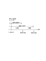
図7は、図6のステップS105及びS106の具体例を示す図である。図7において、第1閾値と、第1閾値よりも大きい第2閾値とがUE100に設定される一例を示している。
図7(a)に示すように、ステップS104で予測した通信停止持続時間が第1閾値未満である場合、UE100は、指示子(RAI)を含む制御信号をgNB200に送信しない。データ通信の停止が一時的なものであって、データ通信が近いうちに再開される場合、UE100はRRCコネクティッドモードを維持することが好ましい。そのため、ステップS104で予測した通信停止持続時間が第1閾値未満である場合、UE100は、指示子(RAI)をgNB200に送信しないこととしている。
図7(b)に示すように、ステップS104で予測した通信停止持続時間が第1閾値以上であって且つ第2閾値未満である場合、UE100は、指示子(RAI)として第1指示子を含む制御信号をgNB200に送信する。
図7(c)に示すように、ステップS104で予測した通信停止持続時間が第2閾値以上である場合、UE100は、指示子(RAI)として、第1指示子とは異なる第2指示子を含む制御信号をgNB200に送信する。
このように、一実施形態において、gNB200が通信停止持続時間の長さを把握できるように、複数段階の指示子を導入している。
ステップS106の制御信号がバッファ状態報告である場合、例えば、第1指示子は「BSR=0」であり、第2指示子は「BSR=-1」であってもよい。「BSR=0」は、UE100のバッファ内の上りリンクデータがゼロであることを示す。「BSR=-1」は、新たに追加されるバッファサイズ値であれば「-1」に限定されず、任意の値であってもよい。或いは、第1指示子及び第2指示子として用いるべきバッファサイズ値は、gNB200からUE100に設定(指定)されてもよい。この設定は、ステップS102においてなされてもよい。
ステップS106の制御信号がRRCメッセージである場合、例えば、第1指示子は「RAI_LOW」であり、第2指示子は「RAI_HIGH」であってもよい。或いは、第1指示子は「第1閾値が満たされた」であり、第2指示子は「第2閾値が満たされた」であってもよい。
図6に示すように、ステップS107において、gNB200は、UE100から受信した制御信号に含まれる指示子に基づいて、UE100をRRCアイドルモードに遷移させるか又はRRCインアクティブモードに遷移させるかを決定する。一実施形態において、UE100から受信した制御信号に含まれる指示子が第1指示子である場合、gNB200は、UE100をRRCインアクティブモードに遷移させると決定する。一方、UE100から受信した制御信号に含まれる指示子が第2指示子である場合、gNB200は、UE100をRRCアイドルモードに遷移させると決定する。
ステップS108において、gNB200は、ステップS107での決定結果に基づいて、専用RRCメッセージの一種であるRRC解放メッセージをUE100に送信する。gNB200は、UE100をRRCインアクティブモードに遷移させると決定した場合、RRCインアクティブモードの設定情報(SuspendConfig)をRRC解放メッセージに含める。Suspend Configは、RRCインアクティブモード用のDRX(discontinuous reception)サイクルであるran-PagingCycleと、RRCインアクティブモード用にUE100に割り当てられる識別子であるfullI-RNTI又はshortI-RNTIとを含む。一方、gNB200は、UE100をRRCアイドルモードに遷移させると決定した場合、SuspendConfigをRRC解放メッセージに含めない。
ステップS109において、UE100は、gNB200から受信したRRC解放メッセージに基づいて、RRCアイドルモード又はRRCインアクティブモードに遷移する。具体的には、UE100は、RRC解放メッセージにSuspendConfigが含まれていればRRCインアクティブモードに遷移し、RRC解放メッセージにSuspendConfigが含まれていなければRRCアイドルモードに遷移する。
このように、一実施形態によれば、gNB200が通信停止持続時間の長さを把握できるため、通信停止持続時間に応じて、RRCアイドルモード及びRRCインアクティブモードのうち適切なモードをUE100に設定できる。
(変更例1)
上述した実施形態において、ステップS106の制御信号がRRCメッセージである場合、ステップS104で予測した通信停止持続時間を示す値を指示子としてRRCメッセージに含めてもよい。例えば、通信停止持続時間を示す値を指示子は、1s,5s,10s,15s,30s,60s,…,1h,…,1dayといったように予め規定された候補の中から選択されてもよい。また、予め規定された候補の中から選択する場合に限らず、予測した通信停止持続時間の値自体を指示子としてRRCメッセージに含めてもよい。
上述した実施形態において、ステップS106の制御信号がRRCメッセージである場合、ステップS104で予測した通信停止持続時間を示す値を指示子としてRRCメッセージに含めてもよい。例えば、通信停止持続時間を示す値を指示子は、1s,5s,10s,15s,30s,60s,…,1h,…,1dayといったように予め規定された候補の中から選択されてもよい。また、予め規定された候補の中から選択する場合に限らず、予測した通信停止持続時間の値自体を指示子としてRRCメッセージに含めてもよい。
この場合、閾値設定(ステップS102)及び閾値比較(ステップS105)を不要としてもよい。或いは、このような指示子を含むRRCメッセージの送信トリガ条件として、1つの閾値をgNB200からUE100に設定(ステップS102)してもよい。
また、RRCメッセージに代えて、新規なMAC CEを導入し、通信停止持続時間を示す指示子を含むMAC CEをUE100からgNB200に送信(ステップS106)してもよい。
(変更例2)
上述した実施形態及びその変更例1において、UE100は、gNB200と通信するデータが存在しなくなったと判定(ステップS103)した後、指示子(RAI)を含む制御信号をgNB200に送信(ステップS106)していた。
上述した実施形態及びその変更例1において、UE100は、gNB200と通信するデータが存在しなくなったと判定(ステップS103)した後、指示子(RAI)を含む制御信号をgNB200に送信(ステップS106)していた。
しかしながら、UE100は、gNB200と通信するデータが存在している際に、gNB200と通信するデータが将来的に存在しなくなると判定してもよい。この場合、実際にgNB200と通信するデータが存在しなくなる前に指示子(RAI)を含む制御信号をgNB200に送信(ステップS106)してもよい。
図8は、実施形態の変更例2に係る移動通信システムの動作を示す図である。ここでは、上述した実施形態の動作を前提として、この動作との相違点について主として説明するが、上述した変更例1の動作を前提としてもよい。
図8に示すように、ステップS201及びS202は、図6のステップS101及びS102と同様である。
ステップS203において、UE100は、gNB200と通信するデータが将来的に存在しなくなるタイミング(以下、「通信停止開始タイミング」と呼ぶ)を予測する。UE100は、UE100のバッファ内の上りリンクデータの量に基づいて通信停止開始タイミングを予測してもよいし、アプリケーションレイヤから得られる情報に基づいて通信停止開始タイミングを予測してもよい。現在バッファに蓄積されているデータ(もしくはバッファ状態報告でgNB200に通知済みのデータ)の送信が完了した時点が、通信停止開始タイミングであってもよい。
ステップS204において、UE100は、上述した実施形態と同様にして、通信停止持続時間を予測する。
ステップS205において、UE100は、ステップS104で予測した通信停止持続時間を複数の閾値と比較する。
ステップS206において、UE100は、通信停止持続時間と複数の閾値との比較結果に基づいて、指示子を含む制御信号をgNB200に送信する。UE100は、ステップS203で予測された通信停止開始タイミングを特定するための情報をさらに制御信号に含める。通信停止開始タイミングを特定するための情報は、絶対時間で表現される情報であってもよいし、制御信号の送信タイミングを基準とした相対時間で表現される情報であってもよい。通信停止開始タイミングを特定するための情報は、gNB200と通信するデータ(上りリンクデータ及び/又は下りリンクデータ)の残りのデータ量で表現される情報であってもよい。
ステップS207において、UE100は、通信停止開始タイミングにおいて、gNB200と通信するデータ(上りリンクデータ及び/又は下りリンクデータ)が存在しない状態になる。
ステップS208において、gNB200は、上述した実施形態と同様にして、UE100をRRCアイドルモードに遷移させるか又はRRCインアクティブモードに遷移させるかを決定する。
ステップS209において、gNB200は、UE100から通知された通信停止開始タイミングに基づいて、RRC解放メッセージをUE100に送信する。例えば、gNB200は、通信停止開始タイミング又はその直後にRRC解放メッセージをUE100に送信する。
ステップS210は、図6のステップS109と同様である。
(その他の実施形態)
上述した実施形態において、UE100に複数のベアラが設定される想定下において各ベアラの区別を行っていなかったが、gNB200は、閾値をUE100のベアラ毎に設定してもよい。
上述した実施形態において、UE100に複数のベアラが設定される想定下において各ベアラの区別を行っていなかったが、gNB200は、閾値をUE100のベアラ毎に設定してもよい。
この場合、gNB200は、閾値をベアラ識別子と紐づけてUE100に設定してもよい。UE100は、指示子(RAI)を、閾値情報に加えてベアラ識別子と紐づけてgNB200に通知してもよい。
これにより、gNB200は、当該RAIによって、通信が一定期間行われないベアラを特定できる。このため、gNB200は、UE100をRRCコネクティッドモードに維持しながら、特定したベアラの設定のみ解放したり、当該ベアラ以外のベアラに適した通信設定を行ったり、最適なセルや周波数へUE100をハンドオーバさせたりすることができる。
例えば、gNB200は、動画受信などの高速通信用のベアラを解放することにより、UE100からキャリアアグリゲーションの設定を解放したり、当該UEを3.5GHz等の高い周波数から800MHzの低い周波数に移したりすることができる。このため、UE100の消費電力を削減することが可能となる。
上述した実施形態において、5Gシステム(NR)について主として説明したが、実施形態に係る動作をLTEに適用してもよい。
上述した実施形態において、UE100は、マシンタイプ通信用途又はIoT用途のUEであってもよい。
なお、UE100又はgNB200が行う各処理をコンピュータに実行させるプログラムが提供されてもよい。プログラムは、コンピュータ読取り可能媒体に記録されていてもよい。コンピュータ読取り可能媒体を用いれば、コンピュータにプログラムをインストールすることが可能である。ここで、プログラムが記録されたコンピュータ読取り可能媒体は、非一過性の記録媒体であってもよい。非一過性の記録媒体は、特に限定されるものではないが、例えば、CD-ROMやDVD-ROM等の記録媒体であってもよい。
また、UE100又はgNB200が行う各処理を実行する回路を集積化し、UE100又はgNB200の少なくとも一部を半導体集積回路(チップセット、SoC)として構成してもよい。
以上、図面を参照して一実施形態について詳しく説明したが、具体的な構成は上述のものに限られることはなく、要旨を逸脱しない範囲内において様々な設計変更等をすることが可能である。
(付記)
序論
RANプレナリは、NRのUEの省電力に関する研究を承認し、以下がRAN2主導の目標として定義づけられた。
序論
RANプレナリは、NRのUEの省電力に関する研究を承認し、以下がRAN2主導の目標として定義づけられた。
ユーザ装置の省電力のための、上位レイヤ手順の拡張の研究
a)追加の省電力信号/チャネル/手順に基づいてUEのページング手順の拡張の研究
b)RRCコネクティッドモードからRRCアイドルモード/RRCインアクティブモードへの効率的な遷移をサポートするUEの省電力手順の拡張の研究
a)追加の省電力信号/チャネル/手順に基づいてUEのページング手順の拡張の研究
b)RRCコネクティッドモードからRRCアイドルモード/RRCインアクティブモードへの効率的な遷移をサポートするUEの省電力手順の拡張の研究
この付記では、RRCコネクティッドモードからRRCアイドルモード/インアクティブモードへの遷移手順で起こりうる問題とUEの省電力のための解決策の方向性が議論されている。
議論
図9に示すように、UEがアイドルモード/インアクティブモードへ遷移することがすでに可能であっても、UEがコネクティッドモードのままであるときに、不必要な電力消費が引き起こされる。このような遅延は、データ送信の終了からRRC解放までの期間、及び、RRC解放の受信からアイドルモード/インアクティブモードへ遷移するプロセスの開始の期間から構成されてもよい。したがって、UEの電力消費を削減するためには、不必要にUEがRRCコネクティッドモードを維持することによる遅延を最小限にすることが望ましい。
図9に示すように、UEがアイドルモード/インアクティブモードへ遷移することがすでに可能であっても、UEがコネクティッドモードのままであるときに、不必要な電力消費が引き起こされる。このような遅延は、データ送信の終了からRRC解放までの期間、及び、RRC解放の受信からアイドルモード/インアクティブモードへ遷移するプロセスの開始の期間から構成されてもよい。したがって、UEの電力消費を削減するためには、不必要にUEがRRCコネクティッドモードを維持することによる遅延を最小限にすることが望ましい。
提案1:RAN2は、不必要にUEがRRCコネクティッドモードを維持する期間を最小限にする解決策を研究すべきである。
前者の遅延に関して、DL/ULデータ送信が完了した後、gNBは出来るだけ早くRRC解放を送信することが期待される。しかしながら、RRC解放の直後に、追加のデータが到着した場合、UEはRRCコネクティッドモードに再遷移する必要がある。そのようなRRC状態の頻繁な前後遷移は望ましくない。したがって、いつRRC解放を送信するかについてより理解するために、gNBは近い将来にDL/ULが発生するかどうかを知る必要があってもよい。NB-IoT及びeMTCでは、UEがBSR=0を送信することによって、UEが近い将来送信又は受信するより多くのデータを保持しているかどうかをeNBに知らせるためにRAI(Release Assistance Indication)が導入された。1つの可能性として、NRに今日のLTEのようにRAIの概念を再利用することがある。しかしながら、NRにはLTEにおいて利用できない追加機能(例えば、インアクティブ状態)があることを考慮すると、既存のRAIに対する何らかの拡張が必要になる場合がある。詳細は、後段で議論され得るだろう。
提案2:RAN2はRAI(Release Assistance Indication)の概念をベースラインとして採用することに同意すべきであり、詳細及び拡張の可能性は更に研究されるべきである。
上記で議論された後者の遅延に関して、現在の仕様ではUEはアイドルモード/インアクティブモードへ遷移するプロセスをRRC解放メッセージの受信後60ミリ秒遅らせる、又は、任意で下位レイヤからのメッセージの確認応答によってアイドルモード/インアクティブモードへ遷移する。そのために、LTEにおける60ミリ秒の遅延はL2確認応答すなわちRLC状態報告及びHARQ ACKを考慮する。このRRC接続解放の処理遅延は、Rel-8から続いているため、NRに適用できるかどうか再検討すべきである。例えば、拡張されたRRC解放メッセージはデータ送信が終了した場合(例えば条件付きのRRC解放の場合)のみ、UEにアイドルモード/インアクティブモードへの遷移を指示することができる。詳細及びその他の解決策はさらに研究されるべきである。
所見1:現在、UEはRRC解放の受信後すぐにはアイドルモードに遷移しない。つまり、60ミリ秒待つか、下位レイヤからの確認応答を待つ。
提案3:RAN2はRRC解放の受信時の遅延を最小限にする解決策を検討すべきである。
本願は、米国仮出願第62/804300号(2019年2月12日出願)の優先権を主張し、その内容の全てが本願明細書に組み込まれている。
Claims (11)
- 移動通信システムにおける通信制御方法であって、
RRC(Radio Resource Control)コネクティッドモードにあるユーザ装置が、前記ユーザ装置が基地局と通信するデータが存在しないと判定する場合、前記データが存在しない状態が持続される持続時間を予測することと、
前記ユーザ装置が、前記予測した持続時間を特定するための指示子を含む制御信号を前記基地局に送信することと、を含む
通信制御方法。 - 前記制御信号を受信した前記基地局が、前記制御信号に含まれる前記指示子に基づいて、前記ユーザ装置をRRCアイドルモードに遷移させるか又はRRCインアクティブモードに遷移させるかを決定することをさらに含む
請求項1に記載の通信制御方法。 - 前記制御信号を送信することは、前記予測した持続時間が第1閾値以上である場合、前記指示子として第1指示子を含む前記制御信号を送信することを有する
請求項1又は2に記載の通信制御方法。 - 前記制御信号を送信することは、前記予測した持続時間が、前記第1閾値よりも大きい第2閾値以上である場合、前記第1指示子とは異なる第2指示子を含む前記制御信号を送信することを有する
請求項3に記載の通信制御方法。 - 前記基地局が、前記ユーザ装置に対して前記第1閾値及び前記第2閾値の少なくとも一方を設定することをさらに含む
請求項4に記載の通信制御方法。 - 前記ユーザ装置が前記基地局と通信するデータが存在している際に、前記ユーザ装置が、前記データが将来的に存在しなくなると判定することをさらに含み、
前記予測することは、前記データが将来的に存在しなくなると判定された場合、前記データが存在しない状態が持続される持続時間を予測することを有する
請求項1乃至5のいずれか1項に記載の通信制御方法。 - 前記制御信号を送信することは、前記データが将来的に存在しなくなると判定された場合、前記データが存在しない状態が開始されるタイミングを特定するための情報をさらに含む前記制御信号を送信することを有する
請求項6に記載の通信制御方法。 - 前記制御信号は、MAC(Medium Access Control)レイヤにおいて送受信されるバッファ状態報告であり、
前記指示子は、前記バッファ状態報告に含まれるバッファサイズ値であり、
前記制御信号を送信することは、前記予測した持続時間に応じた前記バッファサイズ値を含む前記バッファ状態報告を送信することを有する
請求項1乃至7のいずれか1項に記載の通信制御方法。 - 前記制御信号は、RRCレイヤにおいて送受信されるRRCメッセージであり、
前記指示子は、前記RRCメッセージに含まれる情報要素であり、
前記制御信号を送信することは、前記予測した持続時間に応じた前記情報要素を含む前記RRCメッセージを送信することを有する
請求項1乃至8のいずれか1項に記載の通信制御方法。 - 移動通信システムにおけるユーザ装置であって、
RRC(Radio Resource Control)コネクティッドモードにおいて、前記ユーザ装置が基地局と通信するデータが存在しないと判定する場合、前記データが存在しない状態が持続される持続時間を予測する制御部と、
前記予測した持続時間を特定するための指示子を含む制御信号を前記基地局に送信する送信部と、を備える
ユーザ装置。 - 移動通信システムにおける基地局であって、
RRC(Radio Resource Control)コネクティッドモードにあるユーザ装置から、前記ユーザ装置が前記基地局と通信するデータが存在しない状態が持続される持続時間を特定するための指示子を含む制御信号を受信する受信部と、
前記制御信号に含まれる前記指示子に基づいて、前記ユーザ装置をRRCアイドルモードに遷移させるか又はRRCインアクティブモードに遷移させるかを決定する制御部と、を備える
基地局。
Priority Applications (4)
| Application Number | Priority Date | Filing Date | Title |
|---|---|---|---|
| JP2020572282A JP7039739B2 (ja) | 2019-02-12 | 2020-02-12 | 通信制御方法、ユーザ装置、及び基地局 |
| US17/399,899 US12058771B2 (en) | 2019-02-12 | 2021-08-11 | Communication control method, user equipment, and base station |
| JP2022036435A JP7529711B2 (ja) | 2019-02-12 | 2022-03-09 | 通信制御方法、ユーザ装置、及び基地局 |
| US18/769,026 US20240365434A1 (en) | 2019-02-12 | 2024-07-10 | Communication control method, user equipment, and base station |
Applications Claiming Priority (2)
| Application Number | Priority Date | Filing Date | Title |
|---|---|---|---|
| US201962804300P | 2019-02-12 | 2019-02-12 | |
| US62/804300 | 2019-02-12 |
Related Child Applications (1)
| Application Number | Title | Priority Date | Filing Date |
|---|---|---|---|
| US17/399,899 Continuation US12058771B2 (en) | 2019-02-12 | 2021-08-11 | Communication control method, user equipment, and base station |
Publications (1)
| Publication Number | Publication Date |
|---|---|
| WO2020166618A1 true WO2020166618A1 (ja) | 2020-08-20 |
Family
ID=72044479
Family Applications (1)
| Application Number | Title | Priority Date | Filing Date |
|---|---|---|---|
| PCT/JP2020/005381 Ceased WO2020166618A1 (ja) | 2019-02-12 | 2020-02-12 | 通信制御方法、ユーザ装置、及び基地局 |
Country Status (3)
| Country | Link |
|---|---|
| US (2) | US12058771B2 (ja) |
| JP (2) | JP7039739B2 (ja) |
| WO (1) | WO2020166618A1 (ja) |
Families Citing this family (1)
| Publication number | Priority date | Publication date | Assignee | Title |
|---|---|---|---|---|
| EP4183191A4 (en) * | 2020-07-17 | 2023-10-04 | ZTE Corporation | DATA DELIVERY IN ARCHITECTURES DIVIDED BETWEEN CENTRALIZED AND DISTRIBUTED UNITS |
Citations (1)
| Publication number | Priority date | Publication date | Assignee | Title |
|---|---|---|---|---|
| WO2017199789A1 (ja) * | 2016-05-20 | 2017-11-23 | 株式会社Nttドコモ | ユーザ装置、基地局及び信号送信方法 |
Family Cites Families (32)
| Publication number | Priority date | Publication date | Assignee | Title |
|---|---|---|---|---|
| KR101325920B1 (ko) * | 2007-05-02 | 2013-11-07 | 삼성전자주식회사 | 업링크 제어 정보 전송 방법 및 이를 위한 단말 장치 |
| MX2012005873A (es) * | 2009-11-23 | 2012-11-30 | Research In Motion Ltd | Metodo y aparato para transmision de estado/modo. |
| JP5307112B2 (ja) * | 2010-12-17 | 2013-10-02 | シャープ株式会社 | 移動局装置、基地局装置、無線通信システム、制御方法及び集積回路 |
| US8902830B2 (en) * | 2010-12-28 | 2014-12-02 | Motorola Mobility Llc | Energy-saving base station and method |
| US9445261B2 (en) * | 2011-04-27 | 2016-09-13 | Lg Electronics Inc. | Method and apparatus for reporting measurement result |
| US9204354B2 (en) * | 2011-08-11 | 2015-12-01 | Mediatek Inc. | Method for small cell discovery in heterogeneous network |
| WO2013023975A1 (en) * | 2011-08-12 | 2013-02-21 | Research In Motion Limited | Suspending a connection in a wireless communication system |
| US8964678B2 (en) * | 2011-12-23 | 2015-02-24 | Blackberry Limited | Method implemented in an eNodeB base station |
| US8964679B2 (en) * | 2011-12-23 | 2015-02-24 | Blackberry Limited | Method implemented in an eNodeB base station |
| KR101723351B1 (ko) * | 2012-05-29 | 2017-04-05 | 후지쯔 가부시끼가이샤 | 무선 통신 시스템, 무선국 및 기지국 |
| US9462555B2 (en) * | 2012-09-28 | 2016-10-04 | Intel Corporation | Systems and methods for low power consumption in wireless communication systems |
| US9215656B2 (en) * | 2013-06-14 | 2015-12-15 | Blackberry Limited | Self-contained data transfer channel |
| CN105393470B (zh) * | 2013-08-08 | 2018-11-02 | 英特尔Ip公司 | 用于多输入多输出系统中的电子下倾角调节的方法、装置和系统 |
| US9609502B2 (en) * | 2014-02-24 | 2017-03-28 | Intel IP Corporation | Adaptive silencing mechanism for device-to-device (D2D) discovery |
| US9847848B2 (en) * | 2014-05-09 | 2017-12-19 | Samsung Electronics Co., Ltd. | Method and apparatus for performing communication by D2D communication terminal |
| EP3143826A1 (en) * | 2014-05-14 | 2017-03-22 | Sony Corporation | Terminal device, base station, wireless telecommunications system and methods for transitioning between two modes of operation |
| US9820328B2 (en) * | 2014-06-24 | 2017-11-14 | Intel Corporation | Apparatuses, methods, and systems to reduce handover latency in an integrated wireless local area network and cellular network |
| US20160088678A1 (en) * | 2014-09-23 | 2016-03-24 | Telefonaktiebolaget L M Ericsson (Publ) | Network initiated evolved packet core (epc) and ip multimedia subsystem (ims) network usage optimization algorithm for lte capable smartphones connected to wireless lan (wi-fi) network |
| US20170099660A1 (en) * | 2015-10-01 | 2017-04-06 | Electronics And Telecommunications Research Institute | Method and apparatus for transmitting uplink data |
| JP2019054310A (ja) * | 2016-01-29 | 2019-04-04 | シャープ株式会社 | 端末装置、通信方法、および、集積回路 |
| WO2018138854A1 (ja) | 2017-01-27 | 2018-08-02 | 富士通株式会社 | 基地局、無線通信システム、無線端末、及び無線通信方法 |
| US10624150B2 (en) * | 2017-01-30 | 2020-04-14 | FG Innovation Company Limited | Radio resource control connection resume method of wireless communication system |
| JP7377111B2 (ja) * | 2017-07-27 | 2023-11-09 | エルジー エレクトロニクス インコーポレイティド | Edtを実行するための方法及び装置 |
| US11350445B2 (en) * | 2017-08-10 | 2022-05-31 | Kyocera Corporation | Communication control method for controlling a user equipment to perform early data transmission |
| WO2019031427A1 (ja) * | 2017-08-10 | 2019-02-14 | 京セラ株式会社 | 通信制御方法 |
| EP3665996A4 (en) * | 2017-08-11 | 2020-07-29 | ZTE Corporation | SYSTEMS AND METHODS FOR SHARING A RESOURCE POOL IN SIDELINK COMMUNICATIONS |
| WO2019176068A1 (ja) * | 2018-03-15 | 2019-09-19 | 富士通株式会社 | 無線通信システム、基地局、移動局および無線通信方法 |
| EP3804395B1 (en) * | 2018-06-04 | 2025-01-08 | Telefonaktiebolaget LM Ericsson (publ) | Flight path information availability and change indication |
| WO2020026027A1 (en) * | 2018-08-03 | 2020-02-06 | Lenovo (Singapore) Pte. Ltd. | Indicating radio capability changes in an inactive state |
| US11096079B2 (en) * | 2018-10-29 | 2021-08-17 | Apple Inc. | Cell measurements using configured reference signals while in RRC inactive mode |
| US20210176762A1 (en) * | 2018-11-09 | 2021-06-10 | Intel Corporation | Downlink control channel signaling for improved power consumption at a user equipment (ue) |
| US12250704B2 (en) * | 2019-01-25 | 2025-03-11 | Qualcomm Incorporated | Preconfigured uplink resource techniques in wireless communications |
-
2020
- 2020-02-12 JP JP2020572282A patent/JP7039739B2/ja active Active
- 2020-02-12 WO PCT/JP2020/005381 patent/WO2020166618A1/ja not_active Ceased
-
2021
- 2021-08-11 US US17/399,899 patent/US12058771B2/en active Active
-
2022
- 2022-03-09 JP JP2022036435A patent/JP7529711B2/ja active Active
-
2024
- 2024-07-10 US US18/769,026 patent/US20240365434A1/en active Pending
Patent Citations (1)
| Publication number | Priority date | Publication date | Assignee | Title |
|---|---|---|---|---|
| WO2017199789A1 (ja) * | 2016-05-20 | 2017-11-23 | 株式会社Nttドコモ | ユーザ装置、基地局及び信号送信方法 |
Non-Patent Citations (1)
| Title |
|---|
| NOKIA ET. AL.: "Considerations of AS release assistance indication for NB-IoT", 3GPP TSG RAN WG2 #97 R2- 1701664, 3 February 2017 (2017-02-03), XP051212249, Retrieved from the Internet <URL:http://www.3gpp.org/ftp/tsg_ran/WG2_RL2/TSGR2_97/Docs/R2-1701664.zip> * |
Also Published As
| Publication number | Publication date |
|---|---|
| JP2022071185A (ja) | 2022-05-13 |
| JPWO2020166618A1 (ja) | 2021-11-25 |
| JP7529711B2 (ja) | 2024-08-06 |
| JP7039739B2 (ja) | 2022-03-22 |
| US12058771B2 (en) | 2024-08-06 |
| US20240365434A1 (en) | 2024-10-31 |
| US20210378052A1 (en) | 2021-12-02 |
Similar Documents
| Publication | Publication Date | Title |
|---|---|---|
| JP6646037B2 (ja) | 基地局、無線端末及びネットワーク装置 | |
| US20180359669A1 (en) | Communication method, radio terminal, and base station | |
| US12309868B2 (en) | Communication control method | |
| US10021039B2 (en) | Mobile communication system and user terminal | |
| US12408230B2 (en) | Communication control method and user equipment for transitioning between RRC modes | |
| WO2016140274A1 (ja) | 無線端末、ネットワーク装置、及び基地局 | |
| WO2014163138A1 (ja) | 基地局 | |
| JP6174022B2 (ja) | 通信制御方法、ユーザ端末、プロセッサ、及び記憶媒体 | |
| US12010753B2 (en) | Communication control method and user equipment | |
| US20250311037A1 (en) | Method and user equipment | |
| WO2016031662A1 (ja) | 基地局及び無線lan終端装置 | |
| US10973080B2 (en) | Radio terminal, processor, and base station | |
| WO2020196202A1 (ja) | 通信制御方法、ユーザ装置、及び基地局 | |
| US20240365434A1 (en) | Communication control method, user equipment, and base station | |
| WO2017177440A1 (zh) | 状态指示的传输装置、方法以及通信系统 | |
| WO2015020033A1 (ja) | 基地局 | |
| JP7314439B1 (ja) | ユーザ装置、ノード、及び通信方法 |
Legal Events
| Date | Code | Title | Description |
|---|---|---|---|
| 121 | Ep: the epo has been informed by wipo that ep was designated in this application |
Ref document number: 20754887 Country of ref document: EP Kind code of ref document: A1 |
|
| ENP | Entry into the national phase |
Ref document number: 2020572282 Country of ref document: JP Kind code of ref document: A |
|
| NENP | Non-entry into the national phase |
Ref country code: DE |
|
| 122 | Ep: pct application non-entry in european phase |
Ref document number: 20754887 Country of ref document: EP Kind code of ref document: A1 |