WO2020166437A1 - サーバ基盤および物理cpu割当プログラム - Google Patents
サーバ基盤および物理cpu割当プログラム Download PDFInfo
- Publication number
- WO2020166437A1 WO2020166437A1 PCT/JP2020/004195 JP2020004195W WO2020166437A1 WO 2020166437 A1 WO2020166437 A1 WO 2020166437A1 JP 2020004195 W JP2020004195 W JP 2020004195W WO 2020166437 A1 WO2020166437 A1 WO 2020166437A1
- Authority
- WO
- WIPO (PCT)
- Prior art keywords
- cpu
- virtual
- physical cpu
- virtual machine
- physical
- Prior art date
- Legal status (The legal status is an assumption and is not a legal conclusion. Google has not performed a legal analysis and makes no representation as to the accuracy of the status listed.)
- Ceased
Links
Images





Classifications
-
- G—PHYSICS
- G06—COMPUTING OR CALCULATING; COUNTING
- G06F—ELECTRIC DIGITAL DATA PROCESSING
- G06F9/00—Arrangements for program control, e.g. control units
- G06F9/06—Arrangements for program control, e.g. control units using stored programs, i.e. using an internal store of processing equipment to receive or retain programs
- G06F9/44—Arrangements for executing specific programs
- G06F9/455—Emulation; Interpretation; Software simulation, e.g. virtualisation or emulation of application or operating system execution engines
- G06F9/45533—Hypervisors; Virtual machine monitors
- G06F9/45558—Hypervisor-specific management and integration aspects
-
- G—PHYSICS
- G06—COMPUTING OR CALCULATING; COUNTING
- G06F—ELECTRIC DIGITAL DATA PROCESSING
- G06F9/00—Arrangements for program control, e.g. control units
- G06F9/06—Arrangements for program control, e.g. control units using stored programs, i.e. using an internal store of processing equipment to receive or retain programs
- G06F9/46—Multiprogramming arrangements
- G06F9/48—Program initiating; Program switching, e.g. by interrupt
- G06F9/4806—Task transfer initiation or dispatching
- G06F9/4843—Task transfer initiation or dispatching by program, e.g. task dispatcher, supervisor, operating system
- G06F9/485—Task life-cycle, e.g. stopping, restarting, resuming execution
- G06F9/4856—Task life-cycle, e.g. stopping, restarting, resuming execution resumption being on a different machine, e.g. task migration, virtual machine migration
- G06F9/4862—Task life-cycle, e.g. stopping, restarting, resuming execution resumption being on a different machine, e.g. task migration, virtual machine migration the task being a mobile agent, i.e. specifically designed to migrate
-
- G—PHYSICS
- G06—COMPUTING OR CALCULATING; COUNTING
- G06F—ELECTRIC DIGITAL DATA PROCESSING
- G06F9/00—Arrangements for program control, e.g. control units
- G06F9/06—Arrangements for program control, e.g. control units using stored programs, i.e. using an internal store of processing equipment to receive or retain programs
- G06F9/46—Multiprogramming arrangements
- G06F9/50—Allocation of resources, e.g. of the central processing unit [CPU]
- G06F9/5005—Allocation of resources, e.g. of the central processing unit [CPU] to service a request
- G06F9/5027—Allocation of resources, e.g. of the central processing unit [CPU] to service a request the resource being a machine, e.g. CPUs, Servers, Terminals
- G06F9/505—Allocation of resources, e.g. of the central processing unit [CPU] to service a request the resource being a machine, e.g. CPUs, Servers, Terminals considering the load
-
- G—PHYSICS
- G06—COMPUTING OR CALCULATING; COUNTING
- G06F—ELECTRIC DIGITAL DATA PROCESSING
- G06F9/00—Arrangements for program control, e.g. control units
- G06F9/06—Arrangements for program control, e.g. control units using stored programs, i.e. using an internal store of processing equipment to receive or retain programs
- G06F9/46—Multiprogramming arrangements
- G06F9/50—Allocation of resources, e.g. of the central processing unit [CPU]
- G06F9/5061—Partitioning or combining of resources
- G06F9/5077—Logical partitioning of resources; Management or configuration of virtualized resources
-
- G—PHYSICS
- G06—COMPUTING OR CALCULATING; COUNTING
- G06F—ELECTRIC DIGITAL DATA PROCESSING
- G06F9/00—Arrangements for program control, e.g. control units
- G06F9/06—Arrangements for program control, e.g. control units using stored programs, i.e. using an internal store of processing equipment to receive or retain programs
- G06F9/44—Arrangements for executing specific programs
- G06F9/455—Emulation; Interpretation; Software simulation, e.g. virtualisation or emulation of application or operating system execution engines
- G06F9/45533—Hypervisors; Virtual machine monitors
- G06F9/45558—Hypervisor-specific management and integration aspects
- G06F2009/45562—Creating, deleting, cloning virtual machine instances
-
- G—PHYSICS
- G06—COMPUTING OR CALCULATING; COUNTING
- G06F—ELECTRIC DIGITAL DATA PROCESSING
- G06F9/00—Arrangements for program control, e.g. control units
- G06F9/06—Arrangements for program control, e.g. control units using stored programs, i.e. using an internal store of processing equipment to receive or retain programs
- G06F9/44—Arrangements for executing specific programs
- G06F9/455—Emulation; Interpretation; Software simulation, e.g. virtualisation or emulation of application or operating system execution engines
- G06F9/45533—Hypervisors; Virtual machine monitors
- G06F9/45558—Hypervisor-specific management and integration aspects
- G06F2009/4557—Distribution of virtual machine instances; Migration and load balancing
Definitions
- the present invention relates to a server base and a physical CPU allocation program for constructing and operating a computer system.
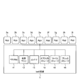
- FIG. 7 is a block diagram of an IaaS (Infrastructure as a Service) base for building and operating a network service.
- the IaaS platform 1 that builds and operates a network service is realized as a server platform.
- a plurality of applications 2a to 2i share resources such as bare metal 11, virtual machine 12, container 13, object storage 14, file storage 15 and block storage 16.
- Each of the applications 2a to 2i can provide a service to the outside and can use a required amount of resources of the IaaS platform 1.
- the IaaS platform 1 has an advantage that a plurality of services can be operated by the applications 2a to 2i.
- the applications 2a to 2i share the IaaS platform 1 to limit available resources.
- Non-Patent Document 1 describes the CPU pinning (fixed) function in OpenStack.
- CPU pinning means limiting the physical CPU used by the virtual CPU for each virtual CPU assigned to the virtual machine. That is, the physical CPU assigned to the processing of the virtual CPU is fixed.
- OpenStack supports CPU pinning by a dedicated method in which a virtual CPU is pinned and occupied by one physical CPU.
- the dedicated method is suitable for services that require a certain amount of performance requirements, such as handling a large amount of load, but excessive resources may occur unless the service has strict latency requirements.
- There is also a shared method in OpenStack in which a physical CPU is shared by a plurality of virtual CPUs. With this shared method, pinning cannot be performed, and it will be mixed with processes of other virtual CPUs.
- an object of the present invention is to enable allocation of physical CPUs in consideration of service requirements of virtual machines.
- the invention according to claim 1 is a server base that generates a virtual CPU and a virtual machine on a physical CPU of a compute and allocates the virtual CPU to the virtual machine.
- One of an instruction to share a physical CPU with a virtual CPU assigned to a machine, an instruction to cause the virtual CPU to occupy and pin the physical CPU, and an instruction to cause the virtual CPU to occupy the physical CPU and not pin A server base comprising: a resource allocation determination unit; and a virtual machine generation management unit that generates a new virtual machine on the physical CPU of the compute in response to an instruction from the resource allocation determination unit. ..
- the resource allocation determination unit instructs the virtual CPU allocated to the virtual machine to share the physical CPU if the load amount of the process executed on the virtual machine is less than or equal to a predetermined value. If the load amount of the process is higher than a predetermined value, the virtual CPU assigned to the virtual machine generates an instruction to occupy the physical CPU of the specified compute, and If the latency requirement is stricter than the predetermined value, an instruction to pin the virtual CPU to the physical CPU is generated, and if the latency requirement of the process is less than the predetermined value, the virtual CPU is pinned to the physical CPU.
- the resource allocation determination unit has no free physical CPU in the compute and there is a non-pinning physical CPU occupied by any virtual CPU on the compute.
- the virtual machine generation management unit generates an instruction to migrate the virtual machine assigned to the virtual CPU occupying the physical CPU to the physical CPU of another compute, and the virtual machine generation management unit responds to the instruction from the resource allocation determination unit.
- the virtual machine generation management unit has no free physical CPU in the compute, and a non-pinning physical CPU occupied by any virtual CPU exists in the compute. In that case, the virtual machine assigned to the virtual CPU occupying the physical CPU is migrated to another compute, and then a new virtual machine is generated on the physical CPU of the compute.
- the server base according to claim 1 or 2 is used.
- a physical CPU allocation program for a virtual CPU by a server base that generates a virtual CPU and a virtual machine on a physical CPU of a compute and allocates the virtual CPU to the virtual machine, Any of an instruction to cause the virtual CPU assigned to the virtual machine to share the physical CPU, an instruction to cause the virtual CPU to occupy and pin the physical CPU, and an instruction to cause the virtual CPU to occupy the physical CPU and not pin And a step of generating a new virtual machine on the physical CPU of the compute.
- the physical CPU is Generating an instruction to move a virtual machine assigned to an occupying virtual CPU to a physical CPU of another compute; migrating the virtual machine to a physical CPU of the other compute;
- the physical CPU allocation program according to claim 5 or 6 for executing the step of generating a new virtual machine on the CPU.
- FIG. 6 It is a sequence diagram in the case of deploying a virtual machine on NUMA provided with a physical CPU from a user terminal.
- 6 is a flowchart for selecting a pinning pattern from application requirements in the present embodiment.
- it is a flowchart which builds the virtual CPU which operates a virtual machine based on a pinning pattern.
- It is a figure which shows the initial state of the system constructed
- It is a block diagram of an IaaS platform for building and operating a network service.
- 9 is a flowchart for selecting a pinning pattern from application requirements in a comparative example.
- 9 is a flowchart for constructing a virtual CPU that operates a virtual machine based on a pinning pattern in a comparative example. It is a figure which shows the system constructed
- FIG. 1 is a sequence diagram when a virtual machine is deployed from a user terminal onto a NUMA (Non-Uniform Memory Access) having a physical CPU.
- NUMA Non-Uniform Memory Access
- the resource allocation determination unit 32, the resource management unit 33, and the virtual machine generation management unit 34 that execute each sequence are included in the IaaS platform 1.
- the IaaS platform 1 is a plurality of server computers. By executing the physical CPU allocation program by this computer, the execution subject of each sequence is embodied.
- the user terminal 31 specifies a pinning pattern for each virtual CPU.
- a pinning pattern for the virtual CPU of the comparative example a pattern for occupying and pinning the physical CPU and a pattern for sharing the physical CPU.
- the pinning pattern of the virtual CPU of the present embodiment has three patterns: a pattern for occupying and pinning the physical CPU, a pattern for occupying the physical CPU and not pinning, and a pattern for sharing the physical CPU. ..
- the resource allocation determination unit 32 instructs the resource management unit 33 to select a resource (S11).
- the resource management unit 33 returns the resource candidates to the resource allocation determination unit 32 (S12).
- the resource allocation determining unit 32 performs scheduling and determines allocation resources.
- the resource allocation determination unit 32 notifies the resource management unit 33 of the allocated resources (S14), and instructs the virtual machine generation management unit 34 to generate a virtual machine (S15).
- the virtual machine generation management unit 34 generates virtual machines and allocates resources based on the scheduling determined in step S13.
- the virtual machine generation management unit 34 notifies the user terminal 31 of the completion of virtual machine generation, and ends the processing in FIG. Thereby, the IaaS platform 1 can generate a virtual CPU and a virtual machine on the physical CPU of the compute and allocate the virtual CPU to this virtual machine.
- the pinning method of the comparative example includes two patterns: a pattern for occupying and pinning the physical CPU and a pattern for sharing the physical CPU.
- the applied service example of the pattern in which the physical CPU is occupied and pinned is for a service that is responsible for a high load amount.
- An example of application service of the pattern of sharing the physical CPU is for a service that does not bear a high load amount.
- FIG. 8 is a flowchart in which the user terminal 31 selects a pinning pattern from application requirements in the comparative example. Before executing step S10 of FIG. 1, the user terminal 31 executes a process of selecting a pinning pattern from the requirements of the application. First, the user terminal 31 determines whether or not the application is responsible for a high load amount (S20).
- the user terminal 31 selects a pattern for occupying and pinning the physical CPU with respect to the virtual CPU assigned to the virtual machine related to this application (S21), and FIG. Ends the process.
- the user terminal 31 selects a pattern for sharing the physical CPU with another virtual CPU for the virtual CPU assigned to the virtual machine related to this application ( S22), and the process of FIG. 8 ends.
- the process of selecting the pinning pattern is not limited to the user terminal 31 and may be performed by the IaaS platform.
- FIG. 9 is a flowchart for generating an instruction to construct a virtual CPU that runs a virtual machine based on a pattern in a comparative example.
- the process of FIG. 9 is executed in step S13 of FIG.
- the resource allocation determination unit 32 determines whether or not the physical CPU is occupied (S30). If the pattern is not such that the physical CPU is occupied (No), the resource allocation determination unit 32 executes processing related to sharing of the physical CPU.
- the resource allocation determining unit 32 determines whether the physical CPU resource of the designated NUMA is free (S31). If the physical CPU resource of the designated NUMA has a free space (Yes), the resource allocation determination unit 32 gives an instruction to deploy the designated virtual CPU on the free physical CPU of the designated NUMA (S33). Ends the process.
- the resource allocation determination unit 32 cannot deploy the virtual machine to the specified NUMA, so the process of FIG. 9 ends abnormally.
- FIG. 10 is a diagram showing a system constructed by the pinning method of the comparative example.
- the NUMA 4 includes four physical CPUs 41a to 41d.
- the physical CPU 41a is occupied and pinned by a virtual CPU 42a assigned to a virtual machine that is responsible for a high load amount.
- the physical CPU 41b is occupied and pinned by the virtual CPU 42b that is assigned to a virtual machine that bears a high load amount and requires low latency.
- the virtual CPUs 42a and 42b are described as a dedicated system.
- the physical CPUs 41c and 41d are shared by the virtual CPUs 42c and 42d. That is, the physical CPUs 41c and 41d have a shared pattern. In order to show this, the virtual CPUs 42c and 42d are described as a shared system in FIG.
- the pinning method of the comparative example is expanded to add a pattern that occupies the physical CPU and does not pin it. By adding this pattern, it becomes possible to allocate CPUs in consideration of service requirements of virtual machines.
- -Patterns that occupy and pin physical CPUs are assigned to the services that you want to process with the highest priority.
- An example of a service to which this pattern is applied is a service that bears a high load amount and requires low latency.
- the low latency requirement means that the latency requirement is strict.
- a service whose only requirement is to handle a high load means that the latency requirement is loose.
- the assigned physical CPU may be changed by another service with high priority.
- An example of a service to which this pattern is applied is a service that requires a high load. By adding this pattern, it becomes possible to allocate the CPU in consideration of the service requirement of the virtual machine.
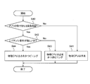
- FIG. 2 is a flowchart for selecting a pinning pattern from application requirements in this embodiment.
- the user terminal 31 determines whether or not the application is responsible for a high load amount (S40). If the application does not bear a high load (No), the user terminal 31 selects a pattern for sharing the physical CPU with another virtual CPU for the virtual CPU assigned to the virtual machine related to this application ( S41), and the process of FIG. 2 ends.
- step S42 if the application bears a high load amount (Yes), the user terminal 31 determines whether or not the requirement of the application is low latency (S42). In step S42, if the latency requirement of the application is strict (Yes), the user terminal 31 selects a pattern for occupying and pinning the physical CPU with respect to the virtual CPU assigned to the virtual machine related to this application (S44). , The process of FIG. 2 ends.
- step S42 if the latency requirement of the application is not strict (No), the user terminal 31 selects a pattern that occupies the physical CPU and does not allow pinning (S43), and ends the process of FIG. That is, the user terminal 31 selects a pattern that occupies the physical CPU and does not allow pinning if the latency requirement of the application is low.
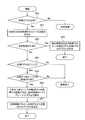
- FIG. 3 is a flowchart for constructing a virtual CPU that runs a virtual machine based on a pinning pattern in the present embodiment.
- the process of FIG. 3 is executed in step S13 of FIG.
- the resource allocation determining unit 32 determines whether or not the physical CPU is occupied (S50). If the pattern is not such that the physical CPU is occupied (No), the resource allocation determination unit 32 executes processing related to sharing the physical CPU.
- the resource allocation determination unit 32 determines the availability of the physical CPU resource of the designated NUMA (S51). In step S52, if the physical CPU resource of the designated NUMA has a free space (Yes), the resource allocation determination unit 32 gives an instruction to deploy the designated virtual CPU on the free physical CPU of the designated NUMA (S53). ), the process of FIG. 3 is completed.
- step S52 if there is no free physical CPU resource of the designated NUMA (No) in step S52, the resource allocation determination unit 32 determines whether or not the physical CPU is a pinning pin pattern (S54).
- step S55 If the physical CPU is not a pattern to be pinned (No), the resource allocation determination unit 32 ends abnormally, and if the physical CPU is to be pinned to a pattern (Yes), the process proceeds to step S55.
- step S55 the resource allocation determination unit 32 determines whether or not the designated NUMA has an occupied and non-pinning physical CPU. If there is no occupied and non-pinning physical CPU in the specified NUMA (No), the resource allocation determination unit 32 terminates abnormally, and if there is an occupied and non-pinning physical CPU (Yes), the process proceeds to step S56. move on.
- step S56 the resource allocation determination unit 32 gives an instruction to migrate the virtual CPU processed by the occupied and non-pinning physical CPU to another NUMA. Further, the resource allocation determination unit 32 gives an instruction to deploy a virtual CPU on the physical CPU (S57), and ends the processing of FIG.
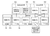
- FIG. 4 is a diagram showing an initial state of a system constructed by the pinning method of this embodiment.
- the NUMA 4b includes one physical CPU 41e. This physical CPU 41e is in an empty state.
- the NUMA 4a includes four physical CPUs 41a to 41d.
- the physical CPU 41a is occupied by the virtual CPU 42a assigned to the virtual machine that is responsible for the high load amount, but is not pinned. That is, the physical CPU 41a is an occupied and non-pinning pattern.
- the physical CPU 41b is occupied and pinned by the virtual CPU 42b that is assigned to a virtual machine that bears a high load amount and requires low latency. That is, the physical CPU 41b is an occupied and pinned pattern.
- the virtual CPUs 42a and 42b are described as a dedicated system.
- the physical CPUs 41c and 41d are shared by the virtual CPUs 42c and 42d. That is, the physical CPUs 41c and 41d have a shared pattern. In order to show this, in FIG. 4, the virtual CPUs 42c and 42d are described as a shared system.
- FIG. 5 is a diagram showing a system constructed by the pinning method of the present embodiment after migration.
- FIG. 5 shows a state after the processing of step S56 in FIG. 3 is completed.
- the virtual CPU 42a that occupied the physical CPU 41a in FIG. 4 has been migrated to the physical CPU 41e included in the NUMA 4b in FIG.
- the physical CPU 41a is in an empty state.
- the other states of the physical CPUs 41b to 41d are the same as the initial states shown in FIG.
- FIG. 6 is a diagram showing the system constructed by the pinning method of the present embodiment after deployment.
- FIG. 6 shows a state after the flow chart of FIG. 3 is completed.
- a virtual CPU 42e in FIG. 6 is deployed on the physical CPU 41a that was in an empty state in FIG.
- the physical CPU 41a is occupied and pinned by a virtual CPU 42e that is assigned to a virtual machine that bears a high load amount and that requires low latency.
- the number of physical CPUs included in NUMA is not limited to four. Further, the number of virtual CPUs deployed on each physical CPU is not limited to one or two.
- B It is not limited to the user terminal to determine whether or not the physical CPU is occupied and whether or not the pinning is performed, depending on the load amount and latency of the application. The IaaS platform may determine whether or not the physical CPU is occupied and whether or not pinning is performed according to the load amount and latency of the application.
- C The determination of migrating the virtual CPU that occupies the physical CPU on NUMA is not limited to the resource allocation determination unit. If there is no free physical CPU on NUMA, the virtual machine generation management unit migrates the virtual CPU that occupies the physical CPU to make this physical CPU empty, and then deploys (generates) a virtual machine.
- IaaS platform (server platform) 11 bare metal 12 virtual machine 13 container 14 object storage 15 file storage 16 block storage 2a to 2i application 31 user terminal 32 resource allocation determination unit 33 resource management unit 34 virtual machine generation management unit 4, 4a, 4b NUMA 41a-41e Physical CPU 42a-42e Virtual CPU
Landscapes
- Engineering & Computer Science (AREA)
- Software Systems (AREA)
- Theoretical Computer Science (AREA)
- Physics & Mathematics (AREA)
- General Engineering & Computer Science (AREA)
- General Physics & Mathematics (AREA)
- Stored Programmes (AREA)
- Multi Processors (AREA)
Abstract
【課題】仮想マシンのサービス要件を考慮してCPUを割り当てる。 【解決手段】IaaS基盤は、コンピュートの物理CPU上に仮想CPUおよび仮想マシンを生成して、仮想マシンに仮想CPUを割り当てる。このIaaS基盤は、仮想マシン上で実行されるプロセスが受け持つ負荷量が所定値よりも高いならば、仮想マシンに割り当てた仮想CPUに、指定されたコンピュートの物理CPUを占有させる指示を生成し、かつ、このプロセスのレイテンシ要件が所定値よりも厳しいならば、仮想CPUを物理CPUにピニングする指示を生成し、このプロセスのレイテンシ要件が所定値よりも緩やかならば、仮想CPUを物理CPUにピニングしない指示を生成するリソース割当決定部32と、リソース割当決定部の指示に応じてコンピュートの物理CPU上に新たな仮想マシンを生成する仮想マシン生成管理部34とを含む。
Description
本発明は、コンピュータシステムを構築して稼動させるためのサーバ基盤および物理CPU割当プログラムに関する。
図7は、ネットワークサービスを構築して稼働させるIaaS(Infrastructure as a Service)基盤の構成図である。
ネットワークサービスを構築して稼動させるIaaS基盤1は、サーバ基盤として実現されている。このIaaS基盤1は、複数のアプリケーション2a~2iがベアメタル11、仮想マシン12、コンテナ13、オブジェクトストレージ14、ファイルストレージ15、ブロックストレージ16などのリソースを共有する。
各アプリケーション2a~2iは、それぞれ外部にサービスを提供するとともに、必要な量のIaaS基盤1のリソースを利用できる。IaaS基盤1では、アプリケーション2a~2iにより複数のサービスを稼働できるメリットがある。その一方で、アプリケーション2a~2iは、IaaS基盤1を共有することで、利用できるリソースが制限される。
ネットワークサービスを構築して稼動させるIaaS基盤1は、サーバ基盤として実現されている。このIaaS基盤1は、複数のアプリケーション2a~2iがベアメタル11、仮想マシン12、コンテナ13、オブジェクトストレージ14、ファイルストレージ15、ブロックストレージ16などのリソースを共有する。
各アプリケーション2a~2iは、それぞれ外部にサービスを提供するとともに、必要な量のIaaS基盤1のリソースを利用できる。IaaS基盤1では、アプリケーション2a~2iにより複数のサービスを稼働できるメリットがある。その一方で、アプリケーション2a~2iは、IaaS基盤1を共有することで、利用できるリソースが制限される。
"CPU topologies",[online],[平成31年1月31日検索],インターネット<URL:https://docs.openstack.org/nova/pike/admin/cpu-topologies.html>
非特許文献1は、OpenStackにおけるCPUピニング(固定)機能について記載されている。CPUピニングとは、仮想マシンに割り当てた仮想CPUごとに、この仮想CPUが使用する物理CPUを制限することをいう。つまりその仮想CPUの処理に割り当てられる物理CPUを固定することである。
CPUピニングにより、仮想CPUの処理が他の物理CPUで実行されることが無いため、キャッシュヒット率の低下を防ぎ、レイテンシ要件が厳しいプロセスを遅延なく実行させることができる。OpenStackは、仮想CPUを1つの物理CPUでピニングして占有するdedicated方式によりCPUピニングをサポートしている。
レイテンシ要件が厳しいサービスの場合、その仮想CPUにdedicated方式を適用することで、キャッシュヒット率の低下を防ぎ、サービスの低レイテンシ化を実現することができる。
高い負荷量を受け持つなど、ある程度の性能要件を求めるサービスならば、dedicated方式がふさわしいが、レイテンシ要件が厳しいサービスでないと余剰なリソースが発生するおそれがある。
また、OpenStackには、複数の仮想CPUで物理CPUを共有するshared方式も存在する。このshared方式ではピニングすることはできず、他の仮想CPUのプロセスと混在することとなる。
高い負荷量を受け持つなど、ある程度の性能要件を求めるサービスならば、dedicated方式がふさわしいが、レイテンシ要件が厳しいサービスでないと余剰なリソースが発生するおそれがある。
また、OpenStackには、複数の仮想CPUで物理CPUを共有するshared方式も存在する。このshared方式ではピニングすることはできず、他の仮想CPUのプロセスと混在することとなる。
そこで、本発明は、仮想マシンのサービス要件を考慮した物理CPUの割り当てを可能とすることを課題とする。
前記した課題を解決するため、請求項1に記載の発明では、コンピュートの物理CPU上に仮想CPUおよび仮想マシンを生成して、前記仮想マシンに前記仮想CPUを割り当てるサーバ基盤であって、前記仮想マシンに割り当てた仮想CPUに物理CPUを共有させる指示、前記仮想CPUに物理CPUを占有させ、かつピニングさせる指示、前記仮想CPUに物理CPUを占有させ、かつピニングさせない指示のうち何れかを生成するリソース割当決定部と、前記リソース割当決定部の指示に応じて、前記コンピュートの前記物理CPU上に新たな仮想マシンを生成する仮想マシン生成管理部と、を含むことを特徴とするサーバ基盤とした。
このようにすることで、仮想マシンのサービス要件を考慮した物理CPUの割り当てができる。
請求項2に記載の発明では、前記リソース割当決定部は、仮想マシン上で実行されるプロセスが受け持つ負荷量が所定値以下ならば、前記仮想マシンに割り当てた仮想CPUに物理CPUを共有させる指示を生成し、前記プロセスが受け持つ負荷量が所定値よりも高いならば、前記仮想マシンに割り当てた仮想CPUに、指定されたコンピュートの前記物理CPUを占有させる指示を生成し、かつ、前記プロセスのレイテンシ要件が前記所定値よりも厳しいならば、前記仮想CPUを前記物理CPUにピニングする指示を生成し、前記プロセスのレイテンシ要件が所定値よりも緩やかならば、前記仮想CPUを前記物理CPUにピニングさせない指示を生成する、ことを特徴とする請求項1に記載のサーバ基盤とした。
このようにすることで、仮想マシン上で実行されるプロセスが受け持つ負荷量要件とレイテンシ要件を考慮した物理CPUの割り当てができる。
請求項3に記載の発明では、前記リソース割当決定部は、前記コンピュートに物理CPUの空きがなく、かつ、前記コンピュート上に何れかの仮想CPUによって占有された非ピニングの物理CPUが在るならば、当該物理CPU上を占有する仮想CPUに割り当てられた仮想マシンを他のコンピュートの物理CPU上に移行させる指示を生成し、前記仮想マシン生成管理部は、前記リソース割当決定部の指示に応じて、前記仮想マシンを前記他のコンピュートの物理CPU上に移行させたのち、前記コンピュートの前記物理CPU上に新たな仮想マシンを生成する、ことを特徴とする請求項1または2に記載のサーバ基盤とした。
このようにすることで、指定されたコンピュート上に物理CPUの空きがない場合であっても、仮想マシンを生成することができる。
請求項4に記載の発明では、前記仮想マシン生成管理部は、前記コンピュートに物理CPUの空きがなく、かつ、前記コンピュート上に何れかの仮想CPUによって占有された非ピニングの物理CPUが在るならば、当該物理CPU上を占有する仮想CPUに割り当てられた仮想マシンを他のコンピュート上に移行させたのち、前記コンピュートの前記物理CPU上に新たな仮想マシンを生成する、ことを特徴とする請求項1または2に記載のサーバ基盤とした。
このようにすることで、指定されたコンピュート上に物理CPUの空きがない場合であっても、仮想マシンを生成することができる。
請求項5に記載の発明では、コンピュートの物理CPU上に仮想CPUおよび仮想マシンを生成して、前記仮想マシンに前記仮想CPUを割り当てるサーバ基盤による仮想CPUに対する物理CPUの割当プログラムであって、コンピュータに、前記仮想マシンに割り当てた仮想CPUに物理CPUを共有させる指示、前記仮想CPUに物理CPUを占有させ、かつピニングさせる指示、前記仮想CPUに物理CPUを占有させ、かつピニングさせない指示のうち何れかを生成する工程、前記コンピュートの前記物理CPU上に新たな仮想マシンを生成する工程、を実行させるための物理CPU割当プログラムとした。
このようにすることで、仮想マシンのサービス要件を考慮した物理CPUの割り当てができる。
請求項6に記載の発明では、仮想マシン上で実行されるプロセスが受け持つ負荷量が所定値以下ならば、前記仮想マシンに割り当てた仮想CPUに物理CPUを共有させる指示を生成し、前記プロセスが受け持つ負荷量が所定値よりも高いならば、前記仮想マシンに割り当てた仮想CPUに、指定されたコンピュートの前記物理CPUを占有させる指示を生成する工程、前記プロセスのレイテンシ要件が前記所定値よりも厳しいならば、前記仮想CPUを前記物理CPUにピニングする指示を生成し、前記プロセスのレイテンシ要件が所定値よりも緩やかならば、前記仮想CPUを前記物理CPUにピニングさせない指示を生成する工程、を実行させるための請求項5に記載の物理CPU割当プログラムとした。
このようにすることで、仮想マシン上で実行されるプロセスが受け持つ負荷量の要件とレイテンシ要件を考慮した物理CPUの割り当てができる。
請求項7に記載の発明では、前記コンピュートに物理CPUの空きがなく、かつ、前記コンピュート上に何れかの仮想CPUによって占有された非ピニングの物理CPUが在るならば、当該物理CPU上を占有する仮想CPUに割り当てられた仮想マシンを他のコンピュートの物理CPU上に移行させる指示を生成する工程、前記仮想マシンを前記他のコンピュートの物理CPU上に移行させたのち、前記コンピュートの前記物理CPU上に新たな仮想マシンを生成する工程、を実行させるための請求項5または6に記載の物理CPU割当プログラムとした。
このようにすることで、指定されたコンピュート上に物理CPUの空きがない場合であっても、仮想マシンを生成することができる。
請求項8に記載の発明では、前記コンピュートに物理CPUの空きがなく、かつ、前記コンピュート上に何れかの仮想CPUによって占有された非ピニングの物理CPUが在るならば、当該物理CPU上を占有する仮想CPUに割り当てられた仮想マシンを他のコンピュート上に移行させたのち、前記コンピュートの前記物理CPU上に新たな仮想マシンを生成するステップ、を実行させるための請求項5または6に記載の物理CPU割当プログラムとした。
このようにすることで、指定されたコンピュート上に物理CPUの空きがない場合であっても、仮想マシンを生成することができる。
仮想マシンのサービス要件を考慮した物理CPUの割り当てが可能となる。
以降、比較例と本発明を実施するための形態とを、各図を参照して詳細に説明する。
図1は、ユーザ端末から物理CPUを備えるNUMA(Non-Uniform Memory Access)上に仮想マシンのデプロイする場合のシーケンス図である。このシーケンス図は、後記する比較例と実施形態に共通するものである。
各シーケンスを実行するリソース割当決定部32、リソース管理部33、仮想マシン生成管理部34は、IaaS基盤1に含まれる。このIaaS基盤1は、複数のサーバコンピュータである。このコンピュータが物理CPU割当プログラムを実行することによって、各シーケンスの実行主体が具現化される。
図1は、ユーザ端末から物理CPUを備えるNUMA(Non-Uniform Memory Access)上に仮想マシンのデプロイする場合のシーケンス図である。このシーケンス図は、後記する比較例と実施形態に共通するものである。
各シーケンスを実行するリソース割当決定部32、リソース管理部33、仮想マシン生成管理部34は、IaaS基盤1に含まれる。このIaaS基盤1は、複数のサーバコンピュータである。このコンピュータが物理CPU割当プログラムを実行することによって、各シーケンスの実行主体が具現化される。
ステップS10におけるVM(Virtual Machine)デプロイ指示において、ユーザ端末31は、仮想CPU毎のピニングパターンを指定する。なお、比較例の仮想CPUのピニングパターンは、物理CPUを占有させ、かつピニングさせるパターンと、物理CPUを共有させるパターンの2通りである。これに対して本実施形態の仮想CPUのピニングパターンは、物理CPUを占有させ、かつピニングさせるパターンと、物理CPUを占有させ、かつピニングさせないパターンと、物理CPUを共有させるパターンの3通りである。
次にリソース割当決定部32は、リソース管理部33にリソース選定を指示する(S11)。リソース管理部33は、リソース割当決定部32にリソース候補を返却する(S12)。
ステップS13において、リソース割当決定部32は、スケジューリングを行うとともに、割当リソースを決定する。
ステップS13において、リソース割当決定部32は、スケジューリングを行うとともに、割当リソースを決定する。
その後、リソース割当決定部32は、リソース管理部33に割当リソースを通知するとともに(S14)、仮想マシン生成管理部34に仮想マシンの生成を指示する(S15)。これにより仮想マシン生成管理部34は、ステップS13で決定されたスケジューリングに基づき、仮想マシンを生成してリソースを割り当てる。
ステップS16において、仮想マシン生成管理部34は、ユーザ端末31に仮想マシンの生成完了を通知し、図1の処理を終了する。
これによりIaaS基盤1は、コンピュートの物理CPU上に仮想CPUおよび仮想マシンを生成して、この仮想マシンに仮想CPUを割り当てることができる。
ステップS16において、仮想マシン生成管理部34は、ユーザ端末31に仮想マシンの生成完了を通知し、図1の処理を終了する。
これによりIaaS基盤1は、コンピュートの物理CPU上に仮想CPUおよび仮想マシンを生成して、この仮想マシンに仮想CPUを割り当てることができる。
《比較例の処理》
比較例のピニング方式は、物理CPUを占有させ、かつピニングさせるパターンと、物理CPUを共有させるパターンの2通りである。
物理CPUを占有させ、かつピニングさせるパターンの適用サービス例は、高い負荷量を受け持つサービス向けである。物理CPUを共有させるパターンの適用サービス例は、高い負荷量を受け持たないサービス向けである。
比較例のピニング方式は、物理CPUを占有させ、かつピニングさせるパターンと、物理CPUを共有させるパターンの2通りである。
物理CPUを占有させ、かつピニングさせるパターンの適用サービス例は、高い負荷量を受け持つサービス向けである。物理CPUを共有させるパターンの適用サービス例は、高い負荷量を受け持たないサービス向けである。
図8は、比較例において、ユーザ端末31が、アプリケーションの要件からピニングパターンを選択するフローチャートである。
図1のステップS10を実行する前に、ユーザ端末31は、アプリケーションの要件からピニングパターンを選択する処理を実行する。
最初、ユーザ端末31は、アプリケーションが高い負荷量を受け持つか否かを判定する(S20)。
図1のステップS10を実行する前に、ユーザ端末31は、アプリケーションの要件からピニングパターンを選択する処理を実行する。
最初、ユーザ端末31は、アプリケーションが高い負荷量を受け持つか否かを判定する(S20)。
ユーザ端末31は、アプリケーションが高い負荷量を受け持つならば(Yes)、このアプリケーションに係る仮想マシンに割り当てた仮想CPUに対して、物理CPUを占有かつピニングさせるパターンを選択し(S21)、図8の処理を終了する。
ユーザ端末31は、アプリケーションが高い負荷量を受け持たないならば(No)、このアプリケーションに係る仮想マシンに割り当てた仮想CPUに対して、物理CPUを他の仮想CPUと共有させるパターンを選択し(S22)、図8の処理を終了する。
なお、ピニングパターンを選択する処理を実行するのは、ユーザ端末31に限定されず、IaaS基盤が実行してもよい。
なお、ピニングパターンを選択する処理を実行するのは、ユーザ端末31に限定されず、IaaS基盤が実行してもよい。
図9は、比較例において、仮想マシンを稼働させる仮想CPUを、パターンに基づいて構築する指示を生成するフローチャートである。この図9の処理は、図1のステップS13において実行される。
リソース割当決定部32は、物理CPUが占有されるパターンか否かを判定する(S30)。リソース割当決定部32は、物理CPUが占有されるパターンではないならば(No)、物理CPUの共有に係る処理を実行する。
リソース割当決定部32は、物理CPUが占有されるパターンか否かを判定する(S30)。リソース割当決定部32は、物理CPUが占有されるパターンではないならば(No)、物理CPUの共有に係る処理を実行する。
リソース割当決定部32は、物理CPUが占有されるパターンならば(Yes)、指定されたNUMAの物理CPUリソースの空きを判定する(S31)。リソース割当決定部32は、指定されたNUMAの物理CPUリソースの空きが有るならば(Yes)、指定NUMAの空き物理CPU上への指定された仮想CPUのデプロイを指示し(S33)、図9の処理を終了する。
リソース割当決定部32は、指定されたNUMAの物理CPUリソースの空きが無いならば(No)、指定されたNUMAへの仮想マシンのデプロイができないため、図9の処理を異常終了する。
図10は、比較例のピニング方式で構築されたシステムを示す図である。
NUMA4は、4個の物理CPU41a~41dを備える。物理CPU41aは、高い負荷量を受け持つ仮想マシンに割り当てた仮想CPU42aによって占有され、かつピニングされている。
NUMA4は、4個の物理CPU41a~41dを備える。物理CPU41aは、高い負荷量を受け持つ仮想マシンに割り当てた仮想CPU42aによって占有され、かつピニングされている。
物理CPU41bには、高い負荷量を受け持ち、かつ低レイテンシを要件とする仮想マシンに割り当てた仮想CPU42bによって占有され、かつピニングされている。これを示すため、図10では仮想CPU42a,42bがdedicate方式として記載されている。
物理CPU41c,41dには、仮想CPU42c,42dによって共有されている。つまり物理CPU41c,41dは、共有のパターンである。これを示すため、図10では仮想CPU42c,42dがshared方式として記載されている。
このシステムに対して、高い負荷量を受け持ち、かつ低レイテンシを要件とする仮想マシンに割り当てた仮想CPUをデプロイしようとしても、物理CPUリソースの空きがないため、この仮想マシンや仮想CPUをデプロイできないという問題がある。
《本実施形態の処理》
本実施形態は、比較例のピニング方式を拡張し、物理CPUを占有させ、かつピニングさせないパターンを加えるというものである。本パターンを加えることで、仮想マシンのサービス要件を考慮したCPUの割り当てが可能となる。
本実施形態は、比較例のピニング方式を拡張し、物理CPUを占有させ、かつピニングさせないパターンを加えるというものである。本パターンを加えることで、仮想マシンのサービス要件を考慮したCPUの割り当てが可能となる。
物理CPUを占有させ、かつピニングさせるパターンは、最優先で処理したいサービスに割り当てられる。このパターンの適用サービス例は、高い負荷量を受け持ち、かつ低レイテンシを要件とするサービスである。ここで低レイテンシの要件とは、レイテンシ要件が厳しいことをいう。これに対して、高い負荷量を受け持つことのみを要件とするサービスとは、レイテンシ要件が緩いことをいう。
物理CPUを占有させ、かつピニングさせないパターンは、優先度の高い他のサービスにより、割り当てられる物理CPUが変更される場合がある。このパターンの適用サービス例は、高い負荷量を受け持つことを要件とするサービスである。このパターンを加えることで、仮想マシンのサービス要件を、より考慮したCPUの割り当てが可能となる。
図2は、本実施形態において、アプリケーションの要件からピニングパターンを選択するフローチャートである。
ユーザ端末31は、アプリケーションが高い負荷量を受け持つか否かを判定する(S40)。
ユーザ端末31は、アプリケーションが高い負荷量を受け持たないならば(No)、このアプリケーションに係る仮想マシンに割り当てた仮想CPUに対して、物理CPUを他の仮想CPUと共有させるパターンを選択し(S41)、図2の処理を終了する。
ユーザ端末31は、アプリケーションが高い負荷量を受け持つか否かを判定する(S40)。
ユーザ端末31は、アプリケーションが高い負荷量を受け持たないならば(No)、このアプリケーションに係る仮想マシンに割り当てた仮想CPUに対して、物理CPUを他の仮想CPUと共有させるパターンを選択し(S41)、図2の処理を終了する。
ユーザ端末31は、アプリケーションが高い負荷量を受け持つならば(Yes)、アプリケーションの要件が低レイテンシであるか否かを判定する(S42)。ステップS42において、ユーザ端末31は、アプリケーションのレイテンシ要件が厳しいならば(Yes)、このアプリケーションに係る仮想マシンに割り当てた仮想CPUに対して、物理CPUを占有かつピニングさせるパターンを選択し(S44)、図2の処理を終了する。
ステップS42において、ユーザ端末31は、アプリケーションのレイテンシ要件が厳しくないならば(No)、物理CPUを占有かつピニングさせないパターンを選択し(S43)、図2の処理を終了する。すなわちユーザ端末31は、アプリケーションのレイテンシ要件が緩いならば、物理CPUを占有かつピニングさせないパターンを選択する。
図3は、本実施形態において、仮想マシンを稼働させる仮想CPUをピニングパターンに基づいて構築するフローチャートである。
この図3の処理は、図1のステップS13において実行される。
リソース割当決定部32は、物理CPUが占有されるパターンか否かを判定する(S50)。リソース割当決定部32は、物理CPUが占有されるパターンでないならば(No)、物理CPUの共有に係る処理を実行する。
この図3の処理は、図1のステップS13において実行される。
リソース割当決定部32は、物理CPUが占有されるパターンか否かを判定する(S50)。リソース割当決定部32は、物理CPUが占有されるパターンでないならば(No)、物理CPUの共有に係る処理を実行する。
リソース割当決定部32は、物理CPUが占有されるパターンならば(Yes)、指定されたNUMAの物理CPUリソースの空きを判定する(S51)。
ステップS52において、リソース割当決定部32は、指定されたNUMAの物理CPUリソースの空きが有るならば(Yes)、指定NUMAの空き物理CPU上への指定された仮想CPUのデプロイを指示し(S53)、図3の処理を終了する。
ステップS52において、リソース割当決定部32は、指定されたNUMAの物理CPUリソースの空きが有るならば(Yes)、指定NUMAの空き物理CPU上への指定された仮想CPUのデプロイを指示し(S53)、図3の処理を終了する。
ステップS52において、リソース割当決定部32は、指定されたNUMAの物理CPUリソースの空きが無いならば(No)、物理CPUがピニングされるバターンであるか否かを判定する(S54)。
リソース割当決定部32は、物理CPUがピニングされるバターンでないならば(No)、異常終了し、物理CPUがピニングされるバターンならば(Yes)、ステップS55の処理に進む。
ステップS55において、リソース割当決定部32は、指定されたNUMAに、占有かつ非ピニングの物理CPUが有るか否かを判定する。リソース割当決定部32は、指定されたNUMAに、占有かつ非ピニングの物理CPUが無ければ(No)異常終了し、占有かつ非ピニングの物理CPUが有れば(Yes)、ステップS56の処理に進む。
ステップS56において、リソース割当決定部32は、占有かつ非ピニングの物理CPUが処理する仮想CPUを、他のNUMAへマイグレーションするように指示する。更にリソース割当決定部32は、当該物理CPU上に仮想CPUのデプロイを指示し(S57)、図3の処理を終了する。
図4は、本実施形態のピニング方式で構築されたシステムの初期状態を示す図である。
NUMA4bは、1個の物理CPU41eを備えている。この物理CPU41eは、空き状態である。
NUMA4aは、4個の物理CPU41a~41dを備える。物理CPU41aは、高い負荷量を受け持つ仮想マシンに割り当てた仮想CPU42aによって占有されているが、ピニングされていない。つまり物理CPU41aは、占有かつ非ピニングのパターンである。
NUMA4bは、1個の物理CPU41eを備えている。この物理CPU41eは、空き状態である。
NUMA4aは、4個の物理CPU41a~41dを備える。物理CPU41aは、高い負荷量を受け持つ仮想マシンに割り当てた仮想CPU42aによって占有されているが、ピニングされていない。つまり物理CPU41aは、占有かつ非ピニングのパターンである。
物理CPU41bは、高い負荷量を受け持ち、かつ低レイテンシを要件とする仮想マシンに割り当てた仮想CPU42bによって占有され、かつピニングされている。つまり物理CPU41bは、占有かつピニングのパターンである。これらを示すため、図4では仮想CPU42a,42bがdedicate方式として記載されている。
物理CPU41c,41dは、仮想CPU42c,42dによって共有されている。つまり物理CPU41c,41dは、共有のパターンである。これを示すため、図4では仮想CPU42c,42dがshared方式として記載されている。
図5は、本実施形態のピニング方式で構築されたシステムのマイグレーション後を示す図である。図5は、図3のステップS56の処理が終了した後の状態を示している。
図4において物理CPU41aを占有していた仮想CPU42aは、図5においてNUMA4bが備える物理CPU41eにマイグレーションされている。そして物理CPU41aは、空き状態である。それ以外の物理CPU41b~41dの状態は、図4に示した初期状態と同様である。
図4において物理CPU41aを占有していた仮想CPU42aは、図5においてNUMA4bが備える物理CPU41eにマイグレーションされている。そして物理CPU41aは、空き状態である。それ以外の物理CPU41b~41dの状態は、図4に示した初期状態と同様である。
図6は、本実施形態のピニング方式で構築されたシステムのデプロイ後を示す図である。図6は、図3のフローチャートが終了した後の状態を示している。
図5において空き状態であった物理CPU41aには、図6において仮想CPU42eがデプロイされている。物理CPU41aは、高い負荷量を受け持ち、かつ低レイテンシを要件とする仮想マシンに割り当てた仮想CPU42eによって占有され、かつピニングされている。
図5において空き状態であった物理CPU41aには、図6において仮想CPU42eがデプロイされている。物理CPU41aは、高い負荷量を受け持ち、かつ低レイテンシを要件とする仮想マシンに割り当てた仮想CPU42eによって占有され、かつピニングされている。
(変形例)
本発明は、上記実施形態に限定されることなく、本発明の趣旨を逸脱しない範囲で、変更実施が可能であり、例えば、次の(a)~(c)のようなものがある。
本発明は、上記実施形態に限定されることなく、本発明の趣旨を逸脱しない範囲で、変更実施が可能であり、例えば、次の(a)~(c)のようなものがある。
(a) NUMAが備える物理CPUの数は4個に限定されない。また、各物理CPU上にデプロイされる仮想CPUの個数は1個または2個に限定されない。
(b) アプリケーションが受け持つ負荷量とレイテンシに応じて、物理CPUの占有の有無およびピニングの有無を判定するのは、ユーザ端末に限定されない。IaaS基盤が、アプリケーションが受け持つ負荷量とレイテンシに応じて、物理CPUの占有の有無およびピニングの有無を判定してもよい。
(c) NUMA上の物理CPUを占有する仮想CPUをマイグレーションするように判断するのは、リソース割当決定部に限定されない。NUMA上に物理CPUの空きが無い場合、仮想マシン生成管理部が物理CPUを占有する仮想CPUをマイグレーションして、この物理CPUを空き状態にしてから仮想マシンをデプロイ(生成)する。
(b) アプリケーションが受け持つ負荷量とレイテンシに応じて、物理CPUの占有の有無およびピニングの有無を判定するのは、ユーザ端末に限定されない。IaaS基盤が、アプリケーションが受け持つ負荷量とレイテンシに応じて、物理CPUの占有の有無およびピニングの有無を判定してもよい。
(c) NUMA上の物理CPUを占有する仮想CPUをマイグレーションするように判断するのは、リソース割当決定部に限定されない。NUMA上に物理CPUの空きが無い場合、仮想マシン生成管理部が物理CPUを占有する仮想CPUをマイグレーションして、この物理CPUを空き状態にしてから仮想マシンをデプロイ(生成)する。
1 IaaS基盤 (サーバ基盤)
11 ベアメタル
12 仮想マシン
13 コンテナ
14 オブジェクトストレージ
15 ファイルストレージ
16 ブロックストレージ
2a~2i アプリケーション
31 ユーザ端末
32 リソース割当決定部
33 リソース管理部
34 仮想マシン生成管理部
4,4a,4b NUMA
41a~41e 物理CPU
42a~42e 仮想CPU
11 ベアメタル
12 仮想マシン
13 コンテナ
14 オブジェクトストレージ
15 ファイルストレージ
16 ブロックストレージ
2a~2i アプリケーション
31 ユーザ端末
32 リソース割当決定部
33 リソース管理部
34 仮想マシン生成管理部
4,4a,4b NUMA
41a~41e 物理CPU
42a~42e 仮想CPU
Claims (8)
- コンピュートの物理CPU上に仮想CPUおよび仮想マシンを生成して、前記仮想マシンに前記仮想CPUを割り当てるサーバ基盤であって、
前記仮想マシンに割り当てた仮想CPUに物理CPUを共有させる指示、前記仮想CPUに物理CPUを占有させ、かつピニングさせる指示、前記仮想CPUに物理CPUを占有させ、かつピニングさせない指示のうち何れかを生成するリソース割当決定部と、
前記リソース割当決定部の指示に応じて、前記コンピュートの前記物理CPU上に新たな仮想マシンを生成する仮想マシン生成管理部と、
を含むことを特徴とするサーバ基盤。 - 前記リソース割当決定部は、仮想マシン上で実行されるプロセスが受け持つ負荷量が所定値以下ならば、前記仮想マシンに割り当てた仮想CPUに物理CPUを共有させる指示を生成し、前記プロセスが受け持つ負荷量が所定値よりも高いならば、前記仮想マシンに割り当てた仮想CPUに、指定されたコンピュートの前記物理CPUを占有させる指示を生成し、かつ、前記プロセスのレイテンシ要件が前記所定値よりも厳しいならば、前記仮想CPUを前記物理CPUにピニングする指示を生成し、前記プロセスのレイテンシ要件が所定値よりも緩やかならば、前記仮想CPUを前記物理CPUにピニングさせない指示を生成する、
ことを特徴とする請求項1に記載のサーバ基盤。 - 前記リソース割当決定部は、前記コンピュートに物理CPUの空きがなく、かつ、前記コンピュート上に何れかの仮想CPUによって占有された非ピニングの物理CPUが在るならば、当該物理CPU上を占有する仮想CPUに割り当てられた仮想マシンを他のコンピュートの物理CPU上に移行させる指示を生成し、
前記仮想マシン生成管理部は、前記リソース割当決定部の指示に応じて、前記仮想マシンを前記他のコンピュートの物理CPU上に移行させたのち、前記コンピュートの前記物理CPU上に新たな仮想マシンを生成する、
ことを特徴とする請求項1または2に記載のサーバ基盤。 - 前記仮想マシン生成管理部は、前記コンピュートに物理CPUの空きがなく、かつ、前記コンピュート上に何れかの仮想CPUによって占有された非ピニングの物理CPUが在るならば、当該物理CPU上を占有する仮想CPUに割り当てられた仮想マシンを他のコンピュート上に移行させたのち、前記コンピュートの前記物理CPU上に新たな仮想マシンを生成する、
ことを特徴とする請求項1または2に記載のサーバ基盤。 - コンピュートの物理CPU上に仮想CPUおよび仮想マシンを生成して、前記仮想マシンに前記仮想CPUを割り当てるサーバ基盤による仮想CPUに対する物理CPUの割当プログラムであって、
コンピュータに、前記仮想マシンに割り当てた仮想CPUに物理CPUを共有させる指示、前記仮想CPUに物理CPUを占有させ、かつピニングさせる指示、前記仮想CPUに物理CPUを占有させ、かつピニングさせない指示のうち何れかを生成する工程、
前記コンピュートの前記物理CPU上に新たな仮想マシンを生成する工程、
を実行させるための物理CPU割当プログラム。 - 仮想マシン上で実行されるプロセスが受け持つ負荷量が所定値以下ならば、前記仮想マシンに割り当てた仮想CPUに物理CPUを共有させる指示を生成し、前記プロセスが受け持つ負荷量が所定値よりも高いならば、前記仮想マシンに割り当てた仮想CPUに、指定されたコンピュートの前記物理CPUを占有させる指示を生成する工程、
前記プロセスのレイテンシ要件が前記所定値よりも厳しいならば、前記仮想CPUを前記物理CPUにピニングする指示を生成し、前記プロセスのレイテンシ要件が所定値よりも緩やかならば、前記仮想CPUを前記物理CPUにピニングさせない指示を生成する工程、
を実行させるための請求項5に記載の物理CPU割当プログラム。 - 前記コンピュートに物理CPUの空きがなく、かつ、前記コンピュート上に何れかの仮想CPUによって占有された非ピニングの物理CPUが在るならば、当該物理CPU上を占有する仮想CPUに割り当てられた仮想マシンを他のコンピュートの物理CPU上に移行させる指示を生成する工程、
前記仮想マシンを前記他のコンピュートの物理CPU上に移行させたのち、前記コンピュートの前記物理CPU上に新たな仮想マシンを生成する工程、
を実行させるための請求項5または6に記載の物理CPU割当プログラム。 - 前記コンピュートに物理CPUの空きがなく、かつ、前記コンピュート上に何れかの仮想CPUによって占有された非ピニングの物理CPUが在るならば、当該物理CPU上を占有する仮想CPUに割り当てられた仮想マシンを他のコンピュート上に移行させたのち、前記コンピュートの前記物理CPU上に新たな仮想マシンを生成するステップ、
を実行させるための請求項5または6に記載の物理CPU割当プログラム。
Priority Applications (1)
| Application Number | Priority Date | Filing Date | Title |
|---|---|---|---|
| US17/427,238 US12026537B2 (en) | 2019-02-13 | 2020-02-04 | Server infrastructure and physical CPU allocation program |
Applications Claiming Priority (2)
| Application Number | Priority Date | Filing Date | Title |
|---|---|---|---|
| JP2019-023092 | 2019-02-13 | ||
| JP2019023092A JP7151530B2 (ja) | 2019-02-13 | 2019-02-13 | サーバ基盤および物理cpu割当プログラム |
Publications (1)
| Publication Number | Publication Date |
|---|---|
| WO2020166437A1 true WO2020166437A1 (ja) | 2020-08-20 |
Family
ID=72044691
Family Applications (1)
| Application Number | Title | Priority Date | Filing Date |
|---|---|---|---|
| PCT/JP2020/004195 Ceased WO2020166437A1 (ja) | 2019-02-13 | 2020-02-04 | サーバ基盤および物理cpu割当プログラム |
Country Status (3)
| Country | Link |
|---|---|
| US (1) | US12026537B2 (ja) |
| JP (1) | JP7151530B2 (ja) |
| WO (1) | WO2020166437A1 (ja) |
Families Citing this family (1)
| Publication number | Priority date | Publication date | Assignee | Title |
|---|---|---|---|---|
| CN116263691A (zh) * | 2022-06-24 | 2023-06-16 | 中移(苏州)软件技术有限公司 | 裸金属服务器云服务热迁移方法和装置 |
Citations (2)
| Publication number | Priority date | Publication date | Assignee | Title |
|---|---|---|---|---|
| JPH02238556A (ja) * | 1989-03-13 | 1990-09-20 | Hitachi Ltd | プロセススケジューリング方式およびマルチプロセッサシステム |
| JP2013250949A (ja) * | 2012-06-04 | 2013-12-12 | Hitachi Ltd | 計算機、仮想化機構、及びスケジューリング方法 |
Family Cites Families (14)
| Publication number | Priority date | Publication date | Assignee | Title |
|---|---|---|---|---|
| US7020800B2 (en) * | 2002-01-24 | 2006-03-28 | Hewlett-Packard Development Company L.P. | System and method for memory failure recovery using lockstep processes |
| US8387049B2 (en) * | 2005-07-15 | 2013-02-26 | International Business Machines Corporation | Facilitating processing within computing environments supporting pageable guests |
| US7765374B2 (en) * | 2007-01-25 | 2010-07-27 | Microsoft Corporation | Protecting operating-system resources |
| JP4715758B2 (ja) * | 2007-01-30 | 2011-07-06 | 株式会社日立製作所 | 仮想計算機システムのプロセッサキャッピング方法 |
| JP5433837B2 (ja) * | 2007-12-05 | 2014-03-05 | 株式会社日立製作所 | 仮想計算機システム、仮想計算機の制御方法及びプログラム |
| JP5035299B2 (ja) * | 2009-06-15 | 2012-09-26 | 株式会社日立製作所 | マルチコアプロセッサ制御方法、その計算機システム、及び管理計算機のプログラム |
| CN102141931B (zh) * | 2011-03-15 | 2014-06-11 | 华为技术有限公司 | 一种创建虚拟机的方法、虚拟机监控器及虚拟机系统 |
| JP5519583B2 (ja) * | 2011-06-20 | 2014-06-11 | 日本電信電話株式会社 | 仮想マシン制御システム、仮想マシン制御装置、仮想マシン制御方法及びプログラム |
| JP6126312B2 (ja) * | 2013-08-26 | 2017-05-10 | ヴイエムウェア インコーポレイテッドVMware,Inc. | 待ち時間の影響を受けやすい仮想マシンをサポートするように構成された仮想マシンモニタ |
| US9558005B2 (en) * | 2014-05-19 | 2017-01-31 | Intel Corporation | Reliable and deterministic live migration of virtual machines |
| US10162656B2 (en) * | 2014-11-26 | 2018-12-25 | Vmware, Inc. | Minimizing guest operating system licensing costs in a processor based licensing model in a virtual datacenter |
| US10452572B2 (en) * | 2016-10-06 | 2019-10-22 | Vmware, Inc. | Automatic system service resource management for virtualizing low-latency workloads that are input/output intensive |
| US10445247B2 (en) * | 2017-06-20 | 2019-10-15 | Red Hat, Inc. | Switching between single-level and two-level page table translations |
| US10599468B2 (en) * | 2017-10-25 | 2020-03-24 | Red Hat, Inc. | Housekeeping virtual processor overcommit for real time virtualization |
-
2019
- 2019-02-13 JP JP2019023092A patent/JP7151530B2/ja active Active
-
2020
- 2020-02-04 WO PCT/JP2020/004195 patent/WO2020166437A1/ja not_active Ceased
- 2020-02-04 US US17/427,238 patent/US12026537B2/en active Active
Patent Citations (2)
| Publication number | Priority date | Publication date | Assignee | Title |
|---|---|---|---|---|
| JPH02238556A (ja) * | 1989-03-13 | 1990-09-20 | Hitachi Ltd | プロセススケジューリング方式およびマルチプロセッサシステム |
| JP2013250949A (ja) * | 2012-06-04 | 2013-12-12 | Hitachi Ltd | 計算機、仮想化機構、及びスケジューリング方法 |
Also Published As
| Publication number | Publication date |
|---|---|
| US12026537B2 (en) | 2024-07-02 |
| JP2020134988A (ja) | 2020-08-31 |
| US20220121468A1 (en) | 2022-04-21 |
| JP7151530B2 (ja) | 2022-10-12 |
Similar Documents
| Publication | Publication Date | Title |
|---|---|---|
| TWI752994B (zh) | 應用的擴容方法、裝置和系統 | |
| Mattess et al. | Scaling mapreduce applications across hybrid clouds to meet soft deadlines | |
| TWI741002B (zh) | 應用程式鏈路的擴容方法、裝置和系統 | |
| JP7081514B2 (ja) | オートスケール型性能保証システム及びオートスケール型性能保証方法 | |
| JP6107801B2 (ja) | 情報処理装置、情報処理システム、タスク処理方法、及び、プログラム | |
| JP2015144020A5 (ja) | ||
| JP7159887B2 (ja) | 仮想化基盤および仮想化基盤のスケーリング管理方法 | |
| WO2019160060A1 (ja) | 仮想リソース管理装置、仮想リソース割り当て方法、および仮想リソース割り当てプログラム | |
| JP2007115246A (ja) | ソフトウェアによって使用される資源を動的に割り当てるための方法及び装置 | |
| JP2012133682A (ja) | コンピュータ、コア割り当て方法およびプログラム | |
| US11755297B2 (en) | Compiling monoglot function compositions into a single entity | |
| JP2010224754A (ja) | リソース割当装置、リソース割当方法、及びプログラム | |
| US10241822B2 (en) | Information processing apparatus for moving virtual machine and method of moving virtual machine | |
| JP7151530B2 (ja) | サーバ基盤および物理cpu割当プログラム | |
| JP2011192049A (ja) | 仮想マシンシステム、自動マイグレーション方法および自動マイグレーションプログラム | |
| Yao et al. | Admission control in YARN clusters based on dynamic resource reservation | |
| KR101558807B1 (ko) | 호스트 프로세서와 협업 프로세서 간에 협업 처리를 위한 프로세서 스케줄링 방법 및 그 방법을 수행하는 호스트 프로세서 | |
| JP6158751B2 (ja) | 計算機資源割当装置及び計算機資源割当プログラム | |
| Awada | Application-container orchestration tools and platform-as-a-service clouds: A survey | |
| JP6600250B2 (ja) | マルチコアcpuを有するパケット転送装置の制御装置及びプログラム | |
| Wang et al. | Schedule distributed virtual machines in a service oriented environment | |
| JP6339978B2 (ja) | リソース割当管理装置およびリソース割当管理方法 | |
| US11461144B2 (en) | Assignment of processes to computational resources | |
| JP6322968B2 (ja) | 情報処理装置、情報処理方法およびプログラム | |
| US20230333893A1 (en) | Pipeline for resource aware workload placement using a euclidean-based projection method |
Legal Events
| Date | Code | Title | Description |
|---|---|---|---|
| 121 | Ep: the epo has been informed by wipo that ep was designated in this application |
Ref document number: 20756648 Country of ref document: EP Kind code of ref document: A1 |
|
| NENP | Non-entry into the national phase |
Ref country code: DE |
|
| 122 | Ep: pct application non-entry in european phase |
Ref document number: 20756648 Country of ref document: EP Kind code of ref document: A1 |