WO2020166362A1 - 通信制御装置、通信制御プログラム、通信制御システム及び通信制御方法 - Google Patents
通信制御装置、通信制御プログラム、通信制御システム及び通信制御方法 Download PDFInfo
- Publication number
- WO2020166362A1 WO2020166362A1 PCT/JP2020/003537 JP2020003537W WO2020166362A1 WO 2020166362 A1 WO2020166362 A1 WO 2020166362A1 JP 2020003537 W JP2020003537 W JP 2020003537W WO 2020166362 A1 WO2020166362 A1 WO 2020166362A1
- Authority
- WO
- WIPO (PCT)
- Prior art keywords
- packet
- switch
- mac address
- communication control
- session
- Prior art date
- Legal status (The legal status is an assumption and is not a legal conclusion. Google has not performed a legal analysis and makes no representation as to the accuracy of the status listed.)
- Ceased
Links
Images





Classifications
-
- H—ELECTRICITY
- H04—ELECTRIC COMMUNICATION TECHNIQUE
- H04L—TRANSMISSION OF DIGITAL INFORMATION, e.g. TELEGRAPHIC COMMUNICATION
- H04L12/00—Data switching networks
- H04L12/28—Data switching networks characterised by path configuration, e.g. LAN [Local Area Networks] or WAN [Wide Area Networks]
Definitions
- the present invention relates to a communication control device, a communication control program, a communication control system, and a communication control method.
- a method of scaling out the communication device is known.
- a method of using the DNS round robin is known to perform load distribution among the load balancers.
- different VIPs are set to the plurality of load balancers in the same domain.
- each load balancer is assigned a group of servers that perform load balancing processing. Then, for example, when the load balancer as the transfer destination of the packet is determined by the DNS round robin, the load balancer receiving the packet transfers the packet to any of the servers assigned to itself.
- the load balancer performs NAT (Network Address Translation) of VIP (Virtual IP: Virtual IP address) to the IP address of the physical server, or terminates SSL/TSL of DH (Diffie-Hellman) key exchange method. It is a stateful device that performs L7 (layer 7) load balancing. Therefore, it is necessary for both the packet (upstream packet) to the server and the response packet (downstream packet) from the server to pass through the same load balancer.
- L7 layer 7 load balancing
- the conventional technology has a problem that a great deal of time and money is required for the setting work for scaling out the communication device.
- the load balancer uses the above-mentioned DNS round robin to perform load distribution, there are cases where work such as new allocation of servers to the load balancer added by scale-out or replacement of accommodation of servers allocated to each load balancer occurs. is there.
- the communication control device of the present invention transmits the first packet when the first packet addressed to the communication device accommodated in the L2 switch is received by the L2 switch.
- a storage unit that stores, in a storage unit, an original MAC address and information identifying a session of the first packet, and a second packet transmitted from a communication device housed in the L2 switch and received by the L2 switch.
- the destination MAC address of the second packet is set to the source MAC of the first packet.
- an updating unit for updating the address.
- FIG. 1 is a diagram showing a configuration example of a communication control system according to the first embodiment.
- FIG. 2 is a diagram illustrating a configuration example of the L2 switch according to the first embodiment.
- FIG. 3 is a flowchart showing a flow of processing for upstream communication of the L2 switch according to the first embodiment.
- FIG. 4 is a flowchart showing a processing flow for downlink communication of the L2 switch according to the first embodiment.
- FIG. 5 is a diagram for explaining a specific example of a processing procedure for the upstream communication of the communication control system 1.
- FIG. 6 is a diagram for explaining a specific example of a processing procedure for one downlink communication of the communication control system.
- FIG. 7 is a diagram for explaining the scale-up.
- FIG. 8 is a diagram for explaining the DNS round robin.
- FIG. 9 is a diagram illustrating an example of a computer that executes a communication control program.
- FIG. 1 is a diagram showing a configuration example of a communication control system according to the first embodiment.
- the communication control system 1 includes a client 10, an L3 switch 20, a plurality of load balancers 30, an L2 switch 40, and a server 50.
- the server 50 is included in the server group.
- the L2 switch 40 is an example of a communication control device.
- the client 10 is connected to the L3 switch 20.
- the L3 switch 20 is also connected to the load balancer 30a, the load balancer 30b, and the load balancer 30c.
- the load balancer 30 when the items common to each load balancer are described, they are simply referred to as the load balancer 30.
- the load balancer 30 is connected to the L2 switch 40.
- the server group is under the control of the L2 switch 40. That is, the L2 switch 40 accommodates the server group.
- Each device of the communication control system 1 may be a physical machine or a virtual machine. Further, the load balancer 30 and the server group may be replaced with devices having other network functions such as CGN (Carrier Grade NAT), VPN device, WAF (Web Application Firewall), and IPS (Intrusion Prevention System).
- CGN Carrier Grade NAT
- VPN device VPN device
- WAF Web Application Firewall
- IPS Intrusion Prevention System
- the communication control system 1 it may be necessary to improve the performance of the load balancer.
- a method for improving the performance of the load balancer there is, for example, scale out in which a load balancer is newly added.
- the number of load balancers in FIG. 1 is an example, and the number of load balancers is not limited to that shown in the figure. Furthermore, the number of load balancers changes due to scale-out.
- the direction of communication from the client 10 to the server group is the up direction.
- the direction of communication from the server group to the client 10 is the downward direction.
- a packet transmitted in the up direction is called an up packet.
- a packet transmitted in the downlink and uplink directions is called a downlink packet.
- the client 10 is a device that communicates with the server 50.
- the L3 switch 20 routes received packets. For example, the L3 switch 20 transfers the upstream packet received from the client 10 to one of the load balancers connected to itself.
- the load balancer 30 operates in the L3 mode and performs load distribution processing of packets to the server group.
- the load balancer 30 is, for example, a stateful device that NATs the VIP set in itself to the IP address of the server 50 and executes L7 (layer 7) load balancing.
- the L3 switch 20 determines the destination load balancer by per-flow ECMP (Equal Cost Multi Path).
- the upstream packet is an example of the first packet.
- VIP is set in each of the load balancers 30.
- the load balancer 30 updates the source MAC address of the upstream packet destined for the server included in the server group to the MAC address set for itself.
- the upstream packet is transmitted from the client 10 to the server 50.
- the downlink packet is supposed to be transmitted from the server 50 to the client 10.
- the load balancer 30 transmits to the L2 switch 40 an upstream packet whose source MAC address has been updated. Further, when the load balancer 30 receives the downlink packet transmitted from the L2 switch 40, the load balancer 30 transmits the downlink packet to the L3 switch 20.
- the downlink packet is an example of the second packet.
- the L2 switch 40 connects the load balancer 30 and the server group.
- the L2 switch 40 receives the packet transmitted from the load balancer 30, routes the received packet, and transmits the packet to the server group.
- the L2 switch 40 also transfers the downlink packet from the server 50 to the load balancer 30 corresponding to the destination MAC address.
- the L2 switch 40 transmits an upstream packet to the server 50 and receives a downstream packet from the server 50.
- the server 50 performs various processes based on the upstream packet received from the client 10 and then transmits a reply packet to the received packet to the client 10 as a downstream packet.
- the load balancer is a stateful device
- the return packet needs to pass through the same load balancer as the load balancer through which the corresponding upstream packet has passed.
- the server 50 cannot recognize the load balancer through which the upstream packet has passed.
- the L2 switch 40 rewrites the destination MAC address of the reply packet received from the server 50 with the MAC address of the load balancer through which the upstream packet corresponding to the reply packet passes.
- the reply packet whose MAC address has been rewritten by the L2 switch 40 is transmitted to the L3 switch 20 and the client 10 via the same load balancer as the load balancer through which the corresponding upstream packet has passed.
- the IP address of the client 10 is described as the source IP address in the IP header of the upstream packet transmitted from the client 10 to the server 50 and arriving at the L2 switch 40 via the load balancer 30c.
- the physical IP address of the server 50 is described as the destination IP address.
- the MAC address of the load balancer 30c is described as the source MAC address
- the MAC address of the server 50 is described as the destination MAC address. Therefore, the L2 switch 40 can acquire the MAC address of the routed load balancer from the L2 header of the upstream packet.
- FIG. 2 is a diagram illustrating a configuration example of the L2 switch according to the first embodiment.
- the L2 switch 40 includes a communication unit 41, an input/output unit 42, a storage unit 43, and a control unit 44.
- the communication unit 41 controls a communication interface with an external device.
- the communication unit 41 receives, for example, an upstream packet via the load balancer 30 and transmits a downstream packet output from the control unit 44 to the server group.
- the input/output unit 42 controls input/output of various information to/from the L2 switch 40.
- the input/output unit 42 receives, for example, input of setting information and the like to the L2 switch 40.
- the storage unit 43 stores various information referred to when the control unit 44 operates.
- the storage unit 43 includes, for example, an area for storing the routing information 431 and the session table 432.
- the routing information 431 is information for L2 to perform routing.
- the routing information 431 is a routing table in which port numbers and MAC addresses are associated with each other.
- the session table 432 stores session information.
- the session information is information that specifies the source MAC address of the upstream packet destined for the server accommodated in the L2 switch 40 and the session of the upstream packet.
- the control unit 44 controls the entire L2 switch 40.
- the control unit 44 has a reception unit 441, a storage unit 442, an update unit 443, and a transmission unit 444.
- the receiving unit 441 receives the upstream packet and the downstream packet via the communication unit 41. Further, the transmission unit 444 routes the upstream packet and the downstream packet, and then transmits them via the communication unit 41.
- the upstream packet addressed to the server group received by the receiving unit 441 is processed by the storage unit 442, which will be described later. Further, the downlink packet from the server group received by the receiving unit 441 is processed by the updating unit 443 described later.
- the storage unit 442 stores the source MAC address of the upstream packet and information identifying the session of the upstream packet. It is stored in the unit 43.
- the information specifying the session of the downlink packet transmitted from the server accommodated in the L2 switch 40 and received by the L2 switch 40 is the same as the information specifying the session of the uplink packet stored in the storage unit 43. If they match, the destination MAC address of the downlink packet is updated to the source MAC address of the uplink packet. Further, for example, the updating unit 443 can update the MAC address using an API of Linux (registered trademark) Kernel called netfilter or a similar library called libnetfilter_queue.
- the storage unit 442 stores the source IP address, source port number, and protocol number of the upstream packet in the storage unit 43 as information for identifying the session of the upstream packet.
- the updating unit 443 determines that the destination IP address, the destination port number, and the protocol number of the downlink packet match the source IP address, the source port number, and the protocol number of the uplink packet stored in the storage unit 43, respectively.
- the destination MAC address of the downlink packet is updated to the source MAC address of the uplink packet.
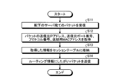
- FIG. 3 is a flowchart showing a flow of processing for upstream communication of the L2 switch according to the first embodiment.
- the L2 switch 40 receives a packet addressed to a subordinate server (step S11).
- the L2 switch 40 acquires the source IP address, source port number, protocol number, and return MAC address of the packet (step S12).
- the transmission source IP address, the transmission source port number, and the protocol number are examples of information that identifies a session.
- the return MAC address is the source MAC address.
- the L2 switch 40 stores the acquired information in the session table 432 (step S13). Then, the L2 switch 40 transmits the packet according to the routing information 431 (step S14).
- FIG. 4 is a flowchart showing a processing flow for downlink communication of the L2 switch according to the first embodiment.
- the L2 switch 40 receives the packet transmitted from the subordinate server (step S21).
- the L2 switch searches the session table 432 with the destination IP address, destination port number, and protocol number of the packet, and acquires the return MAC address of the matching record (step S22).
- the L2 switch 40 updates the destination MAC address of the packet to the acquired return MAC address (step S23). Then, the L2 switch 40 transmits the packet according to the routing information 431 (step S24).
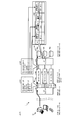
- FIG. 5 is a diagram for explaining a specific example of a processing procedure for upstream communication of the communication control system.
- N clients 10 are installed in the communication control system 1.
- the IP addresses of the clients 10 are “IP-C-1 to N” and the MAC addresses thereof are “MC-C-1 to N”. N".
- IP-L3 IP-L3
- MAC address thereof M-L3
- load balancers 30a, 30b, 30c are installed between the L3 switch 20 and the L2 switch 40.
- IP addresses of the load balancer 30a, the load balancer 30b, and the load balancer 30c are "IP-LB-1", “IP-LB-2”, and “IP-LB-3", respectively.
- the MAC addresses of the load balancer 30a, the load balancer 30b, and the load balancer 30c are "MC-LB-1", “MC-LB-2”, and "MC-LB-3", respectively.
- the VIPs of the load balancers 30a, 30b, 30c are all "VP".
- IP addresses of the servers 50a, 50b, and 50c are "IP-SV-1", “IP-SV-2”, and “IP-SV-3", respectively.
- the MAC addresses of the server 50a, the server 50b, and the server 50c are assumed to be "MC-SV-1", “MC-SV-2”, and "MC-SV-3", respectively.
- Each server 50 is connected to the load balancers 30a, 30b, 30c via the L2 switch 40.
- TO MAC indicates the destination MAC address
- TO IP indicates the destination IP address
- TO Port indicates the destination port number
- FM MAC indicates a source MAC address
- FM IP indicates a source IP address
- FM Port indicates a source port number
- the L3 switch 20 receives a packet (uplink packet) addressed to the VIP “VP” from the client 10 having the IP address “IP-C-1” in the communication control system 1.
- the L3 switch 20 determines the load balancer 30 of the transfer destination of the packet by per-flow ECMP. As a result, the processing load of the upstream packet can be distributed to each load balancer 30.
- the L3 switch 20 determines the transfer destination of the packet to be the load balancer 30a
- the L3 switch 20 sets the header information indicated by reference numeral 501 in the packet and transfers the packet to the load balancer 30a.
- the load balancer 30a sets the header information indicated by reference numeral 502 in the transferred packet and transmits it to the L2 switch 40. That is, the load balancer 30a converts the destination MAC address of the packet transferred from the L3 switch 20 into "MC-SV-1", the destination IP address into "IP-SV-1”, and the source MAC address. Is converted to “MC-LB-1” and transmitted to the L2 switch 40.
- the L2 switch 40 learns the source IP address, source port number, protocol number, and return MAC address from the IP header and L2 header of the received upstream packet. That is, the L2 switch 40 acquires the source IP address, the source port number, the protocol number, and the source MAC address from the IP header and the L2 header of the received packet, and records the acquired information together with the session number in the session table 432. ..
- the items of the session table 432 include the session identification information #, the source port number, the protocol number, and the return MAC address.
- the session table 432 stores “1” as the session identification information #, “IP-C-1” as the transmission source port number, and “xxxx” as the protocol number.
- “6” indicating the tcp protocol is stored as the return MAC address
- “MC-LB-1” is stored as the return MAC address.
- “xxxx” is assumed to be a predetermined numerical value.
- FIG. 6 is a diagram for explaining a specific example of a processing procedure for one downlink communication of the communication control system. Addresses and the like set in each device in FIG. 6 are the same as those in FIG.
- the L2 switch 40 receives from the server 50a a downlink packet having a destination IP address of "IP-C-1", a destination port number of "xxxx", and a protocol number of "6". At this time, an arbitrary value may be set to the destination MAC address of the downlink packet.
- the L2 switch 40 searches the session table 432 for information identifying the same session as the downlink packet, and acquires the return MAC address.
- the L2 switch 40 searches the session table 432 for a record with the source IP address “IP-C-1”, the destination port number “xxx”, and the protocol number “6”, and returns the MAC address for return. As a result, "MC-LB-1" is acquired.
- the L2 switch 40 sets the header information indicated by reference numeral 503 in the downlink packet received from the server 50. That is, the L2 switch 40 updates the destination MAC address to “MC-LB-1” acquired as the return MAC address. As a result, the upstream packet comes to pass through the load balancer 30a.
- the L2 switch 40 when the L2 switch 40 receives the first packet destined for the server accommodated in the L2 switch 40, the L2 switch 40 sends the source MAC address of the first packet and Information for identifying the session of the first packet is stored in the storage unit 43. In addition, the L2 switch 40 transmits information identifying the session of the second packet transmitted from the server housed in the L2 switch 40 and received by the L2 switch 40, to the first packet stored in the storage unit 43. If it matches the information identifying the session, the destination MAC address of the second packet is updated to the source MAC address of the first packet.
- the L2 switch 40 can automatically rewrite the destination MAC address of the reply packet for the upstream packet to the MAC address of the device through which the upstream packet passed. Therefore, according to the first embodiment, when the load balancer 30 is scaled out, the DNS server settings are changed, a new server group is allocated to the added load balancer 30, or a server group allocated to each load balancer 30. It is not necessary to replace the housing, and the labor and cost of setting work can be reduced.
- control is performed so that the upstream packet and the return packet pass through the same load balancer. Can be realized.
- the L2 switch 40 also stores the source IP address, source port number, and protocol number of the first packet in the storage unit 43 as information for identifying the session of the first packet.
- the destination IP address, the destination port number and the protocol number of the second packet are the source IP address, the source port number and the protocol number of the first packet stored in the storage unit 43, respectively. If they match, the destination MAC address of the second packet is updated to the source MAC address of the first packet.
- each load balancer updates the source MAC address of the first packet destined for the server to the MAC address set for itself.
- the MAC address of the load balancer can be uniquely identified.
- the same IP address is set for each load balancer 30, and different MAC addresses are set. Further, the L3 switch 20 determines the destination load balancer by per-flow ECMP when transmitting the first packet to the plurality of load balancers to which the same IP address is set. As a result, in the first embodiment, it is possible to distribute the load of uplink packets.
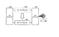
- FIG. 7 is a diagram for explaining the scale-up.
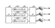
- FIG. 8 is a diagram for explaining the DNS round robin.
- the existing load balancer 30d is replaced with a load balancer 30e having higher performance.
- the scale-up may be performed by adding a module to the existing load balancer 30d.
- a resolution destination VIP for example, VIP3
- VIP3 is set in the load balancer 30h.
- the group of servers subordinate to each load balancer 30 is performed again among the load balancers 30f, 30g, 30h.
- a typical client-server network configuration is a client-firewall-load balancer-server configuration.
- the firewall may be scaled out. Since the firewall is also a stateful device, the technique described in the above embodiment may be applied to the load balancer when the firewall is scaled out in the above configuration. That is, the load balancer in the configuration diagram shown in FIG. 1 may be replaced with a firewall, and the server may be replaced with a load balancer.
- the L2 switch 40 obtains the source MAC address of the upstream packet from the source MAC address set in the L2 header of the upstream packet received via the firewall.
- the MAC address obtained here is the MAC address of the firewall through which the upstream packet has passed.
- the L2 switch 40 stores the source MAC address of the received packet as a return MAC address.
- the L2 switch 40 updates the destination MAC address of the reply packet to the return MAC address when transmitting the reply packet to the upstream packet to the firewall side.
- the reply packet will pass through the same firewall as the firewall through which the upstream packet passed.
- the L2 switch 40 has been described as performing the processing related to the update of the destination MAC address of the downlink packet.
- the processing related to updating the destination MAC address of the downlink packet may be performed by an external communication control device connected to the L2 switch 40.
- the external communication control device has at least the same functions as the storage unit 442, the updating unit 443, and the session table 432 of the L2 switch 40. Then, the external communication control device receives the upstream packet from the L2 switch 40, acquires the information identifying the session and the return MAC address from the received upstream packet, and stores the acquired information. Further, the external communication control device receives the downlink packet from the L2 switch 40, updates the destination MAC address of the downlink packet with the return MAC address in which the downlink packet and the information for identifying the session match, and updates the updated downlink packet. The packet is returned to the L2 switch 40.
- each constituent element of each device shown in the drawings is functionally conceptual, and does not necessarily have to be physically configured as illustrated. That is, the specific form of distribution and integration of each device is not limited to that shown in the figure, and all or a part of them may be functionally or physically distributed in arbitrary units according to various loads or usage conditions, or It can be integrated and configured.
- each processing function performed by each device is realized in whole or in part by a CPU (Central Processing Unit) and a program that is analyzed and executed by the CPU, or a hardware by a wired logic. Can be realized as.
- a CPU Central Processing Unit
- the communication control device (for example, the L2 switch 40) can be implemented by installing a communication control program that executes the above communication control as package software or online software in a desired computer.
- the information processing device can be caused to function as a communication control device.
- the information processing device includes a desktop or notebook personal computer.
- the information processing apparatus includes a mobile communication terminal such as a smartphone, a mobile phone or a PHS (Personal Handyphone System), and a slate terminal such as a PDA (Personal Digital Assistant) in its category.
- FIG. 9 is a diagram illustrating an example of a computer that executes a communication control program.
- the computer 1000 has, for example, a memory 1010 and a CPU 1020.
- the computer 1000 also has a hard disk drive interface 1030, a disk drive interface 1040, a serial port interface 1050, a video adapter 1060, and a network interface 1070. These units are connected by a bus 1080.
- the memory 1010 includes a ROM (Read Only Memory) 1011 and a RAM 1012.
- the ROM 1011 stores, for example, a boot program such as BIOS (Basic Input Output System).
- BIOS Basic Input Output System
- the hard disk drive interface 1030 is connected to the hard disk drive 1090.
- the disk drive interface 1040 is connected to the disk drive 1100.
- a removable storage medium such as a magnetic disk or an optical disk is inserted into the disk drive 1100.
- the serial port interface 1050 is connected to, for example, a mouse 1110 and a keyboard 1120.
- the video adapter 1060 is connected to the display 1130, for example.
- the hard disk drive 1090 stores, for example, an OS 1091, an application program 1092, a program module 1093, and program data 1094. That is, the program that defines each process of communication control is implemented as a program module 1093 in which code executable by a computer is described.
- the program module 1093 is stored in the hard disk drive 1090, for example.
- the hard disk drive 1090 stores a program module 1093 for executing the same processing as the functional configuration in communication control.
- the hard disk drive 1090 may be replaced by SSD.
- the setting data used in the processing of the above-described embodiment is stored as the program data 1094 in, for example, the memory 1010 or the hard disk drive 1090. Then, the CPU 1020 reads the program module 1093 and the program data 1094 stored in the memory 1010 or the hard disk drive 1090 into the RAM 1012 as necessary, and executes the processing of the above-described embodiment.
- the program module 1093 and the program data 1094 are not limited to being stored in the hard disk drive 1090, but may be stored in, for example, a removable storage medium and read by the CPU 1020 via the disk drive 1100 or the like. Alternatively, the program module 1093 and the program data 1094 may be stored in another computer connected via a network (LAN (Local Area Network), WAN (Wide Area Network), etc.). Then, the program module 1093 and the program data 1094 may be read by the CPU 1020 from another computer via the network interface 1070.
- LAN Local Area Network
- WAN Wide Area Network
Landscapes
- Engineering & Computer Science (AREA)
- Computer Networks & Wireless Communication (AREA)
- Signal Processing (AREA)
- Data Exchanges In Wide-Area Networks (AREA)
- Small-Scale Networks (AREA)
Abstract
通信制御装置(例えば、L2スイッチ自体)は、L2スイッチに収容されたサーバを宛先とする第1のパケットがL2スイッチによって受信された場合に、第1のパケットの送信元MACアドレス及び第1のパケットのセッションを特定する情報を記憶部に格納する。また、通信制御装置は、L2スイッチに収容されたサーバから送信され、L2スイッチによって受信された第2のパケットのセッションを特定する情報が、記憶部に格納された第1のパケットのセッションを特定する情報と一致する場合、第2のパケットの宛先MACアドレスを、第1のパケットの送信元MACアドレスに更新する。
Description
本発明は、通信制御装置、通信制御プログラム、通信制御システム及び通信制御方法に関する。
従来、ロードバランサやファイアウォール等のL3(レイヤ3)終端を行う通信装置が性能の限界を超えた際の対応策として、当該通信装置をスケールアウトする方法が知られている。ここで、例えば、ロードバランサのスケールアウトを行う場合、各ロードバランサ間での負荷分散を行うために、DNSラウンドロビンを用いる方法が知られている。DNSラウンドロビンを用いる場合、同じドメインの複数のロードバランサに異なるVIPが設定される。
ここで、各ロードバランサには、負荷分散処理を行うサーバ群が割り当てられているものとする。そして、例えば、DNSラウンドロビンによりパケットの転送先のロードバランサが決定されると、当該パケットを受信したロードバランサは、自身に割り当てられたいずれかのサーバへパケットを転送する。
ここで、ロードバランサは、例えば、VIP(Virtual IP:仮想IPアドレス)を物理サーバのIPアドレスにNAT(Network Address Translation)したり、DH(Diffie-Hellman)鍵交換方式のSSL/TSLを終端させたり、L7(レイヤ7)ロードバランスを実行したりする、ステートフルな装置である。そのため、サーバへのパケット(上りパケット)も当該サーバからの応答パケット(下りパケット)も同じロードバランサを経由する必要がある。ここで、DNSラウンドロビンを用いる方法によれば、上記のようにロードバランサごとにサーバ群が割り当てられるため、上りパケットと下りパケットとで同じロードバランサを経由させることができる。
Maglev: A Fast and Reliable Software Network Load Balancer、[平成31年2月4日検索]、インターネット<URL:https://static.googleusercontent.com/media/research.google.com/ja//pubs/archive/44824.pdf>
しかしながら、従来の技術には、通信装置のスケールアウトのための設定作業に多大な手間やコストを要するという問題がある。例えば、ロードバランサが上記のDNSラウンドロビンを用いて負荷分散を行う場合、スケールアウトにより追加されたロードバランサに対するサーバ群の新規割り当てや各ロードバランサに割り当てるサーバ群の収容替えといった作業が生じる場合がある。
前記した課題を解決するため、本発明の通信制御装置は、L2スイッチに収容された通信装置を宛先とする第1のパケットが前記L2スイッチによって受信された場合に、前記第1のパケットの送信元MACアドレス及び前記第1のパケットのセッションを特定する情報を記憶部に格納する格納部と、前記L2スイッチに収容された通信装置から送信され、前記L2スイッチによって受信された第2のパケットのセッションを特定する情報が、前記記憶部に格納された前記第1のパケットのセッションを特定する情報と一致する場合、前記第2のパケットの宛先MACアドレスを、前記第1のパケットの送信元MACアドレスに更新する更新部と、を有することを特徴とする。
本発明によれば、通信装置のスケールアウトのための設定作業の手間やコストを低減することができる。
以下に、本願に係る通信制御装置、通信制御プログラム、通信制御システム及び通信制御方法の実施形態を図面に基づいて詳細に説明する。なお、本発明は、以下に説明する実施形態により限定されるものではない。
[第1の実施形態の構成]
まず、図1を用いて、第1の実施形態に係る通信制御システムの構成について説明する。図1は、第1の実施形態に係る通信制御システムの構成例を示す図である。図1に示すように、通信制御システム1は、クライアント10、L3スイッチ20、複数のロードバランサ30、L2スイッチ40及びサーバ50を有する。サーバ50は、サーバ群に含まれる。L2スイッチ40は、通信制御装置の一例である。
まず、図1を用いて、第1の実施形態に係る通信制御システムの構成について説明する。図1は、第1の実施形態に係る通信制御システムの構成例を示す図である。図1に示すように、通信制御システム1は、クライアント10、L3スイッチ20、複数のロードバランサ30、L2スイッチ40及びサーバ50を有する。サーバ50は、サーバ群に含まれる。L2スイッチ40は、通信制御装置の一例である。
図1の例では、クライアント10は、L3スイッチ20と接続されている。また、L3スイッチ20は、ロードバランサ30a、ロードバランサ30b及びロードバランサ30cと接続されている。以降、各ロードバランサに共通の事項について説明する場合には、単にロードバランサ30と表記する。
ロードバランサ30はL2スイッチ40と接続されている。また、サーバ群は、L2スイッチ40の配下にあるものとする。つまり、L2スイッチ40は、サーバ群を収容している。
通信制御システム1の各装置は、物理マシンであってもよいし仮想マシンであってもよい。また、ロードバランサ30及びサーバ群は、CGN(Carrier Grade NAT)、VPN装置、WAF(Web Application Firewall)、IPS(Intrusion Prevention System)等の他のネットワーク機能を有する装置に置き換えられてもよい。
通信制御システム1では、ロードバランサの性能アップが必要になる場合がある。ロードバランサの性能アップのための手法には、例えばロードバランサを新たに追加するスケールアウトがある。なお、図1のロードバランサの数は一例であり、ロードバランサの数は図示のものに限られない。さらに、ロードバランサの数はスケールアウト等により変動する。
ここで、クライアント10からサーバ群へ向かう通信の方向を上り方向とする。逆に、サーバ群からクライアント10へ向かう通信の方向を下り方向とする。また、上り方向に送信されるパケットを上りパケットと呼ぶ。また、下り上り方向に送信されるパケットを下りパケットと呼ぶ。
クライアント10は、サーバ50との通信を行う装置である。L3スイッチ20は、受信パケットのルーティングを行う。例えば、L3スイッチ20は、クライアント10から受信した上りパケットを、自身に接続されているいずれかのロードバランサへ転送する。
ロードバランサ30は、L3モードで動作し、サーバ群へのパケットの負荷分散処理を行う。また、ロードバランサ30は、例えば、自身に設定されたVIPをサーバ50のIPアドレスにNATしたり、L7(レイヤ7)ロードバランスを実行したりする、ステートフルな装置である。
ここで、ロードバランサ30のそれぞれには同一のIPアドレスが設定されているものとする。L3スイッチ20は、クライアント10から送信された上りパケットをロードバランサ30に送信する際に、per-flow ECMP(Equal Cost Multi Path)により送信先のロードバランサを決定する。なお、上りパケットは、第1のパケットの一例である。また、ロードバランサ30が仮想マシンである場合、ロードバランサ30のそれぞれにはVIPが設定される。
また、ロードバランサ30のそれぞれには異なるMAC(Media Access Control)アドレスが設定されているものとする。ロードバランサ30は、サーバ群に含まれるサーバを宛先とする上りパケットの送信元MACアドレスを、自身に設定されたMACアドレスに更新する。
ここで、上りパケットはクライアント10からサーバ50に向けて送信されるものとする。また、下りパケットはサーバ50からクライアント10に向けて送信されるものとする。ロードバランサ30は、送信元MACアドレスを更新した上りパケットをL2スイッチ40へ送信する。また、ロードバランサ30は、L2スイッチ40から送信された下りパケットを受信した場合、当該下りパケットをL3スイッチ20に送信する。なお、下りパケットは、第2のパケットの一例である。
L2スイッチ40は、ロードバランサ30とサーバ群とを接続する。このL2スイッチ40は、ロードバランサ30から送信されたパケットを受信し、当該受信したパケットをルーティングしサーバ群に送信する。また、L2スイッチ40は、サーバ50からの下りパケットを宛先MACアドレスに対応するロードバランサ30へ転送する。図1の例では、L2スイッチ40は、サーバ50へ上りパケットを送信し、サーバ50から下りパケットを受信する。
サーバ50は、例えば、クライアント10からの受信した上りパケットに基づき種々の処理を行った後、当該受信したパケットに対する返信パケットを、下りパケットとして当該クライアント10へ送信する。ここで、ロードバランサがステートフルな装置であることから、返信パケットは、対応する上りパケットが経由したロードバランサと同じロードバランサを経由する必要がある。一方で、サーバ50は、上りパケットが経由したロードバランサ認識することができない。
そこで、L2スイッチ40は、サーバ50から受信した返信パケットの宛先MACアドレスを、当該返信パケットに対応する上りパケットが経由したロードバランサのMACアドレスに書き換える。これにより、L2スイッチ40によってMACアドレスが書き換えられた返信パケットは、対応する上りパケットが経由したロードバランサと同じロードバランサを経由して、L3スイッチ20及びクライアント10に送信されることになる。
図1に示すように、クライアント10からサーバ50宛てに送信され、ロードバランサ30cを経由してL2スイッチ40に到着した上りパケットのIPヘッダには、送信元IPアドレスとしてクライアント10のIPアドレスが記載され、宛先IPアドレスとしてサーバ50の物理IPアドレスが記載されている。さらに、当該パケットのL2ヘッダの送信元MACアドレスには、送信元MACアドレスとしてロードバランサ30cのMACアドレスが記載され、宛先MACアドレスとしてサーバ50のMACアドレスが記載されている。このため、L2スイッチ40は、上りパケットのL2ヘッダから、経由したロードバランサのMACアドレスを取得することができる。
図2を用いて、L2スイッチ40の構成について説明する。図2は、第1の実施形態に係るL2スイッチの構成例を示す図である。図2に示すように、L2スイッチ40は、通信部41、入出力部42、記憶部43及び制御部44を有する。
通信部41は、外部装置との通信インタフェースを司る。通信部41は、例えば、ロードバランサ30経由で上りパケットを受信したり、制御部44から出力された下りパケットをサーバ群に送信したりする。入出力部42は、当該L2スイッチ40への各種情報の入出力を司る。入出力部42は、例えば、当該L2スイッチ40への設定情報等の入力を受け付ける。
記憶部43は、制御部44が動作する際に参照する各種情報を記憶する。記憶部43は、例えば、ルーティング情報431及びセッションテーブル432を記憶する領域を備える。ルーティング情報431は、L2がルーティングを行うための情報である。例えば、ルーティング情報431は、ポート番号とMACアドレスが対応付けられたルーティングテーブルである。セッションテーブル432は、セッション情報を記憶する。セッション情報は、L2スイッチ40に収容されたサーバを宛先とする上りパケットの送信元MACアドレス及び当該上りパケットのセッションを特定する情報である。
制御部44は、L2スイッチ40全体の制御を司る。制御部44は、受信部441、格納部442、更新部443及び送信部444を有する。
受信部441は、上りパケット及び下りパケットを通信部41経由で受信する。また、送信部444は、上りパケット及び下りパケットをルーティングを行った上で通信部41経由で送信する。ここで、受信部441が受信したサーバ群宛ての上りパケットに対しては、後述する格納部442による処理が行われる。また、受信部441が受信したサーバ群からの下りパケットに対しては、後述する更新部443による処理が行われる。
格納部442は、L2スイッチ40に収容されたサーバを宛先とする上りパケットがL2スイッチ40によって受信された場合に、当該上りパケットの送信元MACアドレス及び当該上りパケットのセッションを特定する情報を記憶部43に格納する。
更新部443は、L2スイッチ40に収容されたサーバから送信され、L2スイッチ40によって受信された下りパケットのセッションを特定する情報が、記憶部43に格納された上りパケットのセッションを特定する情報と一致する場合、当該下りパケットの宛先MACアドレスを、当該上りパケットの送信元MACアドレスに更新する。また、例えば、更新部443は、netfilterと呼ばれるLinux(登録商標) Kernelが持つAPIや、libnetfilter_queueと呼ばれる類似のライブラリ等を用いてMACアドレスの更新を行うことができる。
例えば、格納部442は、上りパケットのセッションを特定する情報として、上りパケットの送信元IPアドレス、送信元ポート番号及びプロトコル番号を記憶部43に格納する。このとき、更新部443は、下りパケットの宛先IPアドレス、宛先ポート番号及びプロトコル番号が、それぞれ記憶部43に格納された上りパケットの送信元IPアドレス、送信元ポート番号及びプロトコル番号と一致する場合、下りパケットの宛先MACアドレスを、上りパケットの送信元MACアドレスに更新する。
[第1の実施形態の処理手順]
図3を用いて、L2スイッチ40の上り方向の通信に対する処理の流れを説明する。図3は、第1の実施形態に係るL2スイッチの上り方向の通信に対する処理の流れを示すフローチャートである。
図3を用いて、L2スイッチ40の上り方向の通信に対する処理の流れを説明する。図3は、第1の実施形態に係るL2スイッチの上り方向の通信に対する処理の流れを示すフローチャートである。
図3に示すように、まず、L2スイッチ40は、配下のサーバ宛てのパケットを受信する(ステップS11)。次に、L2スイッチ40は、パケットの送信元IPアドレス、送信元ポート番号、プロトコル番号及び返却用MACアドレスを取得する(ステップS12)。ここで、送信元IPアドレス、送信元ポート番号及びプロトコル番号は、セッションを特定する情報の一例である。また、返却用MACアドレスは、送信元MACアドレスである。
ここで、L2スイッチ40は、取得した情報をセッションテーブル432に格納する(ステップS13)。そして、L2スイッチ40は、ルーティング情報431にしたがいパケットを送信する(ステップS14)。
図4を用いて、L2スイッチ40の下り方向の通信に対する処理の流れを説明する。図4は、第1の実施形態に係るL2スイッチの下り方向の通信に対する処理の流れを示すフローチャートである。
図4に示すように、まず、L2スイッチ40は、配下のサーバから送信されたパケットを受信する(ステップS21)。次に、L2スイッチは、パケットの宛先IPアドレス、宛先ポート番号、プロトコル番号でセッションテーブル432を検索し、一致するレコードの返却用MACアドレスを取得する(ステップS22)。
ここで、L2スイッチ40は、パケットの宛先MACアドレスを、取得した返却用MACアドレスに更新する(ステップS23)。そして、L2スイッチ40は、ルーティング情報431にしたがいパケットを送信する(ステップS24)。
[第1の実施形態の処理手順の具体例]
図5を用いて、通信制御システムの1の上り方向の通信に対する処理手順の具体例を説明する。図5は、通信制御システムの上り方向の通信に対する処理手順の具体例を説明するための図である。
図5を用いて、通信制御システムの1の上り方向の通信に対する処理手順の具体例を説明する。図5は、通信制御システムの上り方向の通信に対する処理手順の具体例を説明するための図である。
図5に示すように、通信制御システム1には、N台のクライアント10が設置され、クライアント10それぞれのIPアドレスは「IP-C-1~N」、MACアドレスは「MC-C-1~N」であるものとする。
また、L3スイッチ20のIPアドレスは「IP-L3」、MACアドレスは「MC-L3」であるものとする。さらに、L3スイッチ20とL2スイッチ40との間には、ロードバランサ30a、30b、30cが設置される。
ロードバランサ30a、ロードバランサ30b及びロードバランサ30cのIPアドレスは、それぞれ「IP-LB-1」、「IP-LB-2」及び「IP-LB-3」であるものとする。また、ロードバランサ30a、ロードバランサ30b及びロードバランサ30cのMACアドレスは、それぞれ「MC-LB-1」、「MC-LB-2」及び「MC-LB-3」であるものとする。なお、ロードバランサ30a、30b、30cのVIPは、いずれも「VP」であるものとする。
また、サーバ50は3台設置され、サーバ50a、サーバ50b及びサーバ50cのIPアドレスは、それぞれ「IP-SV-1」、「IP-SV-2」及び「IP-SV-3」であるものとする。また、サーバ50a、サーバ50b及びサーバ50cのMACアドレスは、それぞれ「MC-SV-1」、「MC-SV-2」及び「MC-SV-3」であるものとする。それぞれのサーバ50は、L2スイッチ40経由でロードバランサ30a、30b、30cに接続される。
なお、図5における「TO MAC」は、宛先MACアドレスを示し、「TO IP」は宛先IPアドレスを示し、「TO Port」は宛先ポート番号を示す。また、図5における「FM MAC」は、送信元MACアドレスを示し、「FM IP」は送信元IPアドレスを示し、「FM Port」は送信元ポート番号を示す。
通信制御システム1において、L3スイッチ20がIPアドレス「IP-C-1」のクライアント10から、VIP「VP」宛のパケット(上りパケット)を受信した場合を考える。この場合、まず、L3スイッチ20は、per-flow ECMPにより、当該パケットの転送先のロードバランサ30を決定する。これにより、上りパケットの処理負荷を各ロードバランサ30に分散させることができる。
ここで、例えば、L3スイッチ20が、当該パケットの転送先をロードバランサ30aに決定した場合、L3スイッチ20は、符号501に示すヘッダ情報を当該パケットに設定してロードバランサ30aに転送する。その後、ロードバランサ30aは、転送されたパケットに符号502に示すヘッダ情報を設定してL2スイッチ40へ送信する。つまり、ロードバランサ30aは、L3スイッチ20から転送されたパケットの宛先MACアドレスを「MC-SV-1」に変換し、宛先IPアドレスを「IP-SV-1」に変換し、送信元MACアドレスを「MC-LB-1」に変換して、L2スイッチ40へ送信する。
そして、L2スイッチ40は、受信した上りパケットのIPヘッダ及びL2ヘッダから、送信元IPアドレス、送信元ポート番号、プロトコル番号、返却用MACアドレスを学習する。つまり、L2スイッチ40は、受信パケットのIPヘッダ及びL2ヘッダから、送信元IPアドレス、送信元ポート番号、プロトコル番号、送信元MACアドレス取得し、取得した情報をセッション番号とともにセッションテーブル432に記録する。
ここで、図5に示すように、セッションテーブル432の項目には、セッション識別情報#、送信元ポート番号、プロトコル番号及び返却用MACアドレスが含まれる。図5の例では、セッションテーブル432には、セッション識別情報#として「1」が格納され、送信元ポート番号として「IP-C-1」が格納され、プロトコル番号として「xxxx」が格納され、返却用MACアドレスとしてtcpプロトコルを示す「6」が格納され、返却用MACアドレスとして「MC-LB-1」が格納される。ただし、「xxxx」は所定の数値であるものとする。
図6を用いて、通信制御システムの1の下り方向の通信に対する処理手順の具体例を説明する。図6は、通信制御システムの1の下り方向の通信に対する処理手順の具体例を説明するための図である。図6における各装置に設定されたアドレス等は、図5のもとの同様である。
まず、L2スイッチ40は、宛先IPアドレスが「IP-C-1」、宛先ポート番号が「xxxx」、プロトコル番号が「6」である下りパケットをサーバ50aから受信する。このとき、下りパケットの送信先MACアドレスには任意の値が設定されていてよい。
そして、L2スイッチ40は、セッションテーブル432から下りパケットと同じセッションを特定する情報を検索し、返却用MACアドレスを取得する。ここでは、L2スイッチ40は、セッションテーブル432から、送信元IPアドレスが「IP-C-1」、送信先ポート番号「xxxx」、プロトコル番号「6」であるレコードを検索し、返却用MACアドレスとして「MC-LB-1」を取得する。
さらに、L2スイッチ40は、サーバ50から受信した下りパケットに符号503に示すヘッダ情報を設定する。つまり、L2スイッチ40は、送信先MACアドレスを、返却用MACアドレスとして取得した「MC-LB-1」に更新する。これにより、上りパケットは、ロードバランサ30aを経由するようになる。
[第1の実施形態の効果]
これまで説明してきたように、L2スイッチ40は、L2スイッチ40に収容されたサーバを宛先とする第1のパケットがL2スイッチ40によって受信された場合に、第1のパケットの送信元MACアドレス及び第1のパケットのセッションを特定する情報を記憶部43に格納する。また、L2スイッチ40は、L2スイッチ40に収容されたサーバから送信され、L2スイッチ40によって受信された第2のパケットのセッションを特定する情報が、記憶部43に格納された第1のパケットのセッションを特定する情報と一致する場合、第2のパケットの宛先MACアドレスを、第1のパケットの送信元MACアドレスに更新する。
これまで説明してきたように、L2スイッチ40は、L2スイッチ40に収容されたサーバを宛先とする第1のパケットがL2スイッチ40によって受信された場合に、第1のパケットの送信元MACアドレス及び第1のパケットのセッションを特定する情報を記憶部43に格納する。また、L2スイッチ40は、L2スイッチ40に収容されたサーバから送信され、L2スイッチ40によって受信された第2のパケットのセッションを特定する情報が、記憶部43に格納された第1のパケットのセッションを特定する情報と一致する場合、第2のパケットの宛先MACアドレスを、第1のパケットの送信元MACアドレスに更新する。
このように、L2スイッチ40は、上りパケットに対する返信パケットの宛先MACアドレスを、上りパケットが経由した装置のMACアドレスに自動的に書き換えることができる。このため、第1の実施形態によれば、ロードバランサ30のスケールアウトを行う際、DNSサーバの設定変更や、追加されたロードバランサ30に対するサーバ群の新規割り当てや各ロードバランサ30に割り当てるサーバ群の収容替えが不要になり、設定作業の手間やコストを低減することができる。
また、同様の宛先MACアドレスをサーバに直接実装することが困難な場合であっても、第1の実施形態によれば、上りパケットと返信パケットが同一のロードバランサを経由するようにする制御を実現することができる。
また、L2スイッチ40は、第1のパケットのセッションを特定する情報として、第1のパケットの送信元IPアドレス、送信元ポート番号及びプロトコル番号を記憶部43に格納する。また、L2スイッチ40は、第2のパケットの宛先IPアドレス、宛先ポート番号及びプロトコル番号が、それぞれ記憶部43に格納された第1のパケットの送信元IPアドレス、送信元ポート番号及びプロトコル番号と一致する場合、第2のパケットの宛先MACアドレスを、第1のパケットの送信元MACアドレスに更新する。このように、第1の実施形態では、上りパケットである第1のパケットのヘッダに設定された各値を使って、容易にセッションを特定することができる。
また、ロードバランサ30のそれぞれには異なるMACアドレスが設定される。また、各ロードバランサは、サーバを宛先とする第1のパケットの送信元MACアドレスを、自身に設定されたMACアドレスに更新する。これにより、第1の実施形態では、ロードバランサのMACアドレスを一意に特定することが可能になる。
ロードバランサ30のそれぞれには同一のIPアドレスが設定され、かつ異なるMACアドレスが設定される。また、L3スイッチ20は、同一のIPアドレスが設定された複数のロードバランサに第1のパケットを送信する際に、per-flow ECMPにより送信先のロードバランサを決定する。これにより、第1の実施形態では、上りパケットの負荷分散が可能になる。
ここで、第1の実施形態の効果を、既存技術であるロードバランサのスケールアップ及びDNSラウンドロビンによるロードバランサのスケールアウトと対比しながら説明する。図7は、スケールアップについて説明するための図である。図8は、DNSラウンドロビンについて説明するための図である。
図7に示すように、ロードバランサのスケールアップにおいては、既存のロードバランサ30dがより性能の高いロードバランサ30eにリプレースされる。また、スケールアップは、既存のロードバランサ30dに対しモジュールを追加することにより行われてもよい。
また、図8に示すように、DNSラウンドロビンによるロードバランサのスケールアウトにおいては、同一ドメインに対する解決先VIP(例えば、VIP3)が追加され、DNSラウンドロビンによる負荷分散が行われる。例えば、ロードバランサ30f(VIP1)、ロードバランサ30g(VIP2)に対し、ロードバランサ30hを追加した場合、ロードバランサ30hにVIP3が設定される。また、ロードバランサ30hを追加した場合、ロードバランサ30f、30g、30hの間で、各ロードバランサ30の配下のサーバ群のグルーピングが再度行われる。
(1)設定作業及び設定コストについて
上記のロードバランサ30dのスケールアップを行う場合、サーバ群のゲートウェイの設定変更が必要であり、DNSラウンドロビンによりロードバランサ30のスケールアウトを行う場合、追加するロードバランサ30hに割り当てるサーバ群の設定と、DNSサーバの設定変更が必要である。しかし、第1の実施形態の場合、上記の設定変更等は不要である。
上記のロードバランサ30dのスケールアップを行う場合、サーバ群のゲートウェイの設定変更が必要であり、DNSラウンドロビンによりロードバランサ30のスケールアウトを行う場合、追加するロードバランサ30hに割り当てるサーバ群の設定と、DNSサーバの設定変更が必要である。しかし、第1の実施形態の場合、上記の設定変更等は不要である。
(2)サーバ分割損について
上記のロードバランサ30dのスケールアップを行う場合、サーバ群の再分割は発生しないのでいわゆるサーバの分割損は発生しないが、DNSラウンドロビンによりロードバランサ30のスケールアウトを行う場合、30f、30g、30hに対し割り当てるサーバ群の再グルーピングを行う必要があるのでサーバの分割損が発生する。一方、第1の実施形態の場合、上記のサーバ分割損は発生しない。
上記のロードバランサ30dのスケールアップを行う場合、サーバ群の再分割は発生しないのでいわゆるサーバの分割損は発生しないが、DNSラウンドロビンによりロードバランサ30のスケールアウトを行う場合、30f、30g、30hに対し割り当てるサーバ群の再グルーピングを行う必要があるのでサーバの分割損が発生する。一方、第1の実施形態の場合、上記のサーバ分割損は発生しない。
(3)切り戻しについて
上記のロードバランサ30dのスケールアップを行う場合において、切り戻しを行う際には長い時間を要する。また、DNSラウンドロビンによりロードバランサ30のスケールアウトを行う場合において、切り戻しを行う際には、DNSサーバのレコード削除とサーバの戻し作業が発生するため作業の手間がかかる。また、DNSサーバのキャッシュのTTL(Time To Live)があるため、作業結果の反映にも時間がかかる。一方、第1の実施形態の場合、切り戻しを行う際には、L3スイッチ20のルーティング情報を削除すればよいので切り戻しに要する作業は少ない。
上記のロードバランサ30dのスケールアップを行う場合において、切り戻しを行う際には長い時間を要する。また、DNSラウンドロビンによりロードバランサ30のスケールアウトを行う場合において、切り戻しを行う際には、DNSサーバのレコード削除とサーバの戻し作業が発生するため作業の手間がかかる。また、DNSサーバのキャッシュのTTL(Time To Live)があるため、作業結果の反映にも時間がかかる。一方、第1の実施形態の場合、切り戻しを行う際には、L3スイッチ20のルーティング情報を削除すればよいので切り戻しに要する作業は少ない。
以上説明したとおり、本実施形態のシステムによれば、ロードバランサ30のスケールアウト時の設定作業及び設定コストを低減することができる。また、ロードバランサ30の配下のサーバ群の分割損も発生せず、また切り戻しを行う際の設定作業及び設定コストも低減することができる。
[その他の実施形態]
なお、典型的なクライアント~サーバ間のネットワーク構成として、クライアント-ファイアウォール-ロードバランサ-サーバという構成がある。このような構成において、ファイアウォールのスケールアウトを行う場合もある。ここで、ファイアウォールもステートフルな装置であるので、上記の構成においてファイアウォールのスケールアウトを行う場合に、ロードバランサに上記の実施形態で述べた技術を適用してもよい。つまり、図1に示した構成図におけるロードバランサをファイアウォールに置き換え、サーバをロードバランサに置き換えてもよい。
なお、典型的なクライアント~サーバ間のネットワーク構成として、クライアント-ファイアウォール-ロードバランサ-サーバという構成がある。このような構成において、ファイアウォールのスケールアウトを行う場合もある。ここで、ファイアウォールもステートフルな装置であるので、上記の構成においてファイアウォールのスケールアウトを行う場合に、ロードバランサに上記の実施形態で述べた技術を適用してもよい。つまり、図1に示した構成図におけるロードバランサをファイアウォールに置き換え、サーバをロードバランサに置き換えてもよい。
この場合、L2スイッチ40は、ファイアウォール経由で受信した上りパケットのL2ヘッダに設定された送信元MACアドレスにより、当該上りパケットの送信元MACアドレスを得る。ここで得たMACアドレスは、当該上りパケットが経由したファイアウォールのMACアドレスである。そして、L2スイッチ40は、当該受信パケットの送信元MACアドレスを返却用MACアドレスとして記憶しておく。そして、L2スイッチ40は、当該上りパケットに対する返信パケットをファイアウォール側へ送信する際、当該返信パケットの宛先MACアドレスを、返却用MACアドレスに更新する。これにより、返信パケットは、上りパケットが経由したファイアウォールと同じファイアウォールを経由することになる。
また、上記の実施形態では、下りパケットの宛先MACアドレスの更新に関する処理をL2スイッチ40が行うものとして説明した。一方で、下りパケットの宛先MACアドレスの更新に関する処理は、L2スイッチ40と接続された外部の通信制御装置によって行われてもよい。
ここで、外部の通信制御装置は、少なくともL2スイッチ40の格納部442、更新部443及びセッションテーブル432と同等の機能を有する。そして、外部の通信制御装置は、L2スイッチ40から上りパケットを受け取り、受け取った上りパケットからセッションを特定する情報及び返却用MACアドレスを取得し、取得した情報を記憶しておく。さらに、外部の通信制御装置は、L2スイッチ40から下りパケットを受け取り、当該下りパケットとセッションを特定する情報が一致する返却用MACアドレスで当該下りパケットの宛先MACアドレスを更新し、更新済みの下りパケットをL2スイッチ40に返す。
[システム構成等]
また、図示した各装置の各構成要素は機能概念的なものであり、必ずしも物理的に図示のように構成されていることを要しない。すなわち、各装置の分散及び統合の具体的形態は図示のものに限られず、その全部又は一部を、各種の負荷や使用状況等に応じて、任意の単位で機能的又は物理的に分散又は統合して構成することができる。さらに、各装置にて行われる各処理機能は、その全部又は任意の一部が、CPU(Central Processing Unit)及び当該CPUにて解析実行されるプログラムにて実現され、あるいは、ワイヤードロジックによるハードウェアとして実現され得る。
また、図示した各装置の各構成要素は機能概念的なものであり、必ずしも物理的に図示のように構成されていることを要しない。すなわち、各装置の分散及び統合の具体的形態は図示のものに限られず、その全部又は一部を、各種の負荷や使用状況等に応じて、任意の単位で機能的又は物理的に分散又は統合して構成することができる。さらに、各装置にて行われる各処理機能は、その全部又は任意の一部が、CPU(Central Processing Unit)及び当該CPUにて解析実行されるプログラムにて実現され、あるいは、ワイヤードロジックによるハードウェアとして実現され得る。
また、本実施形態において説明した各処理のうち、自動的に行われるものとして説明した処理の全部又は一部を手動的に行うこともでき、あるいは、手動的に行われるものとして説明した処理の全部又は一部を公知の方法で自動的に行うこともできる。この他、上記文書中や図面中で示した処理手順、制御手順、具体的名称、各種のデータやパラメータを含む情報については、特記する場合を除いて任意に変更することができる。
[プログラム]
一実施形態として、通信制御装置(例えば、L2スイッチ40)は、パッケージソフトウェアやオンラインソフトウェアとして上記の通信制御を実行する通信制御プログラムを所望のコンピュータにインストールさせることによって実装できる。例えば、上記の通信制御プログラムを情報処理装置に実行させることにより、情報処理装置を通信制御装置として機能させることができる。ここで言う情報処理装置には、デスクトップ型又はノート型のパーソナルコンピュータが含まれる。また、その他にも、情報処理装置にはスマートフォン、携帯電話機やPHS(Personal Handyphone System)等の移動体通信端末、さらには、PDA(Personal Digital Assistant)等のスレート端末等がその範疇に含まれる。
一実施形態として、通信制御装置(例えば、L2スイッチ40)は、パッケージソフトウェアやオンラインソフトウェアとして上記の通信制御を実行する通信制御プログラムを所望のコンピュータにインストールさせることによって実装できる。例えば、上記の通信制御プログラムを情報処理装置に実行させることにより、情報処理装置を通信制御装置として機能させることができる。ここで言う情報処理装置には、デスクトップ型又はノート型のパーソナルコンピュータが含まれる。また、その他にも、情報処理装置にはスマートフォン、携帯電話機やPHS(Personal Handyphone System)等の移動体通信端末、さらには、PDA(Personal Digital Assistant)等のスレート端末等がその範疇に含まれる。
図9は、通信制御プログラムを実行するコンピュータの一例を示す図である。コンピュータ1000は、例えば、メモリ1010、CPU1020を有する。また、コンピュータ1000は、ハードディスクドライブインタフェース1030、ディスクドライブインタフェース1040、シリアルポートインタフェース1050、ビデオアダプタ1060、ネットワークインタフェース1070を有する。これらの各部は、バス1080によって接続される。
メモリ1010は、ROM(Read Only Memory)1011及びRAM1012を含む。ROM1011は、例えば、BIOS(Basic Input Output System)等のブートプログラムを記憶する。ハードディスクドライブインタフェース1030は、ハードディスクドライブ1090に接続される。ディスクドライブインタフェース1040は、ディスクドライブ1100に接続される。例えば磁気ディスクや光ディスク等の着脱可能な記憶媒体が、ディスクドライブ1100に挿入される。シリアルポートインタフェース1050は、例えばマウス1110、キーボード1120に接続される。ビデオアダプタ1060は、例えばディスプレイ1130に接続される。
ハードディスクドライブ1090は、例えば、OS1091、アプリケーションプログラム1092、プログラムモジュール1093、プログラムデータ1094を記憶する。すなわち、通信制御の各処理を規定するプログラムは、コンピュータにより実行可能なコードが記述されたプログラムモジュール1093として実装される。プログラムモジュール1093は、例えばハードディスクドライブ1090に記憶される。例えば、通信制御における機能構成と同様の処理を実行するためのプログラムモジュール1093が、ハードディスクドライブ1090に記憶される。なお、ハードディスクドライブ1090は、SSDにより代替されてもよい。
また、上述した実施形態の処理で用いられる設定データは、プログラムデータ1094として、例えばメモリ1010やハードディスクドライブ1090に記憶される。そして、CPU1020は、メモリ1010やハードディスクドライブ1090に記憶されたプログラムモジュール1093やプログラムデータ1094を必要に応じてRAM1012に読み出して、上述した実施形態の処理を実行する。
なお、プログラムモジュール1093やプログラムデータ1094は、ハードディスクドライブ1090に記憶される場合に限らず、例えば着脱可能な記憶媒体に記憶され、ディスクドライブ1100等を介してCPU1020によって読み出されてもよい。あるいは、プログラムモジュール1093及びプログラムデータ1094は、ネットワーク(LAN(Local Area Network)、WAN(Wide Area Network)等)を介して接続された他のコンピュータに記憶されてもよい。そして、プログラムモジュール1093及びプログラムデータ1094は、他のコンピュータから、ネットワークインタフェース1070を介してCPU1020によって読み出されてもよい。
10 クライアント
20 L3スイッチ
30、30a、30b、30c ロードバランサ
40 L2スイッチ
41 通信部
42 入出力部
43 記憶部
44 制御部
431 ルーティング情報
432 セッションテーブル
441 受信部
442 格納部
443 更新部
444 送信部
50、50a、50b、50c サーバ
20 L3スイッチ
30、30a、30b、30c ロードバランサ
40 L2スイッチ
41 通信部
42 入出力部
43 記憶部
44 制御部
431 ルーティング情報
432 セッションテーブル
441 受信部
442 格納部
443 更新部
444 送信部
50、50a、50b、50c サーバ
Claims (6)
- L2スイッチに収容された通信装置を宛先とする第1のパケットが前記L2スイッチによって受信された場合に、前記第1のパケットの送信元MACアドレス及び前記第1のパケットのセッションを特定する情報を記憶部に格納する格納部と、
前記L2スイッチに収容された通信装置から送信され、前記L2スイッチによって受信された第2のパケットのセッションを特定する情報が、前記記憶部に格納された前記第1のパケットのセッションを特定する情報と一致する場合、前記第2のパケットの宛先MACアドレスを、前記第1のパケットの送信元MACアドレスに更新する更新部と、
を有することを特徴とする通信制御装置。 - 前記格納部は、前記第1のパケットのセッションを特定する情報として、前記第1のパケットの送信元IPアドレス、送信元ポート番号及びプロトコル番号を前記記憶部に格納し、
前記更新部は、第2のパケットの宛先IPアドレス、宛先ポート番号及びプロトコル番号が、それぞれ前記記憶部に格納された前記第1のパケットの送信元IPアドレス、送信元ポート番号及びプロトコル番号と一致する場合、前記第2のパケットの宛先MACアドレスを、前記第1のパケットの送信元MACアドレスに更新することを特徴とする請求項1に記載の通信制御装置。 - L2スイッチに収容された通信装置を宛先とする第1のパケットが前記L2スイッチによって受信された場合に、前記第1のパケットの送信元MACアドレス及び前記第1のパケットのセッションを特定する情報を記憶部に格納する格納ステップと、
前記L2スイッチに収容された通信装置から送信され、前記L2スイッチによって受信された第2のパケットのセッションを特定する情報が、前記記憶部に格納された前記第1のパケットのセッションを特定する情報と一致する場合、前記第2のパケットの宛先MACアドレスを、前記第1のパケットの送信元MACアドレスに更新する更新ステップと、
をコンピュータに実行させることを特徴とする通信制御プログラム。 - 通信装置を配下に持つL2スイッチを制御する通信制御装置と、前記L2スイッチと接続され、それぞれにMACアドレスが設定された複数のロードバランサと、を有する通信制御システムであって、
前記ロードバランサのそれぞれは、
前記通信装置を宛先とする第1のパケットの送信元MACアドレスを、自身に設定されたMACアドレスに更新する第1の更新部を有し、
前記通信制御装置は、
前記第1のパケットが前記L2スイッチによって受信された場合に、前記第1のパケットの送信元MACアドレス及び前記第1のパケットのセッションを特定する情報を記憶部に格納する格納部と、
前記L2スイッチに収容された通信装置から送信され、前記L2スイッチによって受信された第2のパケットのセッションを特定する情報が、前記記憶部に格納された前記第1のパケットのセッションを特定する情報と一致する場合、前記第2のパケットの宛先MACアドレスを、前記第1のパケットの送信元MACアドレスに更新する第2の更新部と、
を有することを特徴とする通信制御システム。 - 前記複数のロードバランサと接続されたL3スイッチをさらに有し、
前記複数のロードバランサのそれぞれには同一のIPアドレスが設定され、
前記L3スイッチは、
同一のIPアドレスが設定された前記複数のロードバランサに前記第1のパケットを送信する際に、per-flow ECMPにより送信先のロードバランサを決定する決定部を有することを特徴とする請求項4に記載の通信制御システム。 - 通信装置を配下に持つL2スイッチを制御する通信制御装置と、前記L2スイッチと接続され、それぞれにMACアドレスが設定された複数のロードバランサと、を有する通信制御システムによって実行される通信制御方法であって、
前記ロードバランサのそれぞれが、前記通信装置を宛先とする第1のパケットの送信元MACアドレスを、自身に設定されたMACアドレスに更新する第1の更新工程と、
前記通信制御装置が、前記第1のパケットが前記L2スイッチによって受信された場合に、前記第1のパケットの送信元MACアドレス及び前記第1のパケットのセッションを特定する情報を記憶部に格納する格納工程と、
前記通信制御装置が、前記L2スイッチに収容された通信装置から送信され、前記L2スイッチによって受信された第2のパケットのセッションを特定する情報が、前記記憶部に格納された前記第1のパケットのセッションを特定する情報と一致する場合、前記第2のパケットの宛先MACアドレスを、前記第1のパケットの送信元MACアドレスに更新する第2の更新工程と、
を含むことを特徴とする通信制御方法。
Applications Claiming Priority (2)
| Application Number | Priority Date | Filing Date | Title |
|---|---|---|---|
| JP2019-023996 | 2019-02-13 | ||
| JP2019023996A JP2020136743A (ja) | 2019-02-13 | 2019-02-13 | 通信制御装置、通信制御プログラム、通信制御システム及び通信制御方法 |
Publications (1)
| Publication Number | Publication Date |
|---|---|
| WO2020166362A1 true WO2020166362A1 (ja) | 2020-08-20 |
Family
ID=72044938
Family Applications (1)
| Application Number | Title | Priority Date | Filing Date |
|---|---|---|---|
| PCT/JP2020/003537 Ceased WO2020166362A1 (ja) | 2019-02-13 | 2020-01-30 | 通信制御装置、通信制御プログラム、通信制御システム及び通信制御方法 |
Country Status (2)
| Country | Link |
|---|---|
| JP (1) | JP2020136743A (ja) |
| WO (1) | WO2020166362A1 (ja) |
Citations (5)
| Publication number | Priority date | Publication date | Assignee | Title |
|---|---|---|---|---|
| JP2005027304A (ja) * | 2003-06-30 | 2005-01-27 | Microsoft Corp | 接続操作を用いるネットワーク負荷分散 |
| JP2013016044A (ja) * | 2011-07-04 | 2013-01-24 | Fujitsu Ltd | ファイアウォール装置およびファイアウォール装置の制御方法 |
| WO2014172497A1 (en) * | 2013-04-16 | 2014-10-23 | Amazon Technologies, Inc. | Multipath routing in a distributed load balancer |
| JP2019068297A (ja) * | 2017-10-02 | 2019-04-25 | 日本電信電話株式会社 | 通信装置、通信制御システム、および、通信制御方法 |
| JP2019176323A (ja) * | 2018-03-28 | 2019-10-10 | 日本電信電話株式会社 | 通信装置、通信制御システム、通信制御方法及び通信制御プログラム |
-
2019
- 2019-02-13 JP JP2019023996A patent/JP2020136743A/ja active Pending
-
2020
- 2020-01-30 WO PCT/JP2020/003537 patent/WO2020166362A1/ja not_active Ceased
Patent Citations (5)
| Publication number | Priority date | Publication date | Assignee | Title |
|---|---|---|---|---|
| JP2005027304A (ja) * | 2003-06-30 | 2005-01-27 | Microsoft Corp | 接続操作を用いるネットワーク負荷分散 |
| JP2013016044A (ja) * | 2011-07-04 | 2013-01-24 | Fujitsu Ltd | ファイアウォール装置およびファイアウォール装置の制御方法 |
| WO2014172497A1 (en) * | 2013-04-16 | 2014-10-23 | Amazon Technologies, Inc. | Multipath routing in a distributed load balancer |
| JP2019068297A (ja) * | 2017-10-02 | 2019-04-25 | 日本電信電話株式会社 | 通信装置、通信制御システム、および、通信制御方法 |
| JP2019176323A (ja) * | 2018-03-28 | 2019-10-10 | 日本電信電話株式会社 | 通信装置、通信制御システム、通信制御方法及び通信制御プログラム |
Non-Patent Citations (4)
| Title |
|---|
| "Web system acceleration in the EC era, part 3, SSL Accelerator that can connect dozens of users, PCI board type followed 4-6 Y by box type, too", NIKKEI INTERNET TECHNOLOGY, 22 November 2000 (2000-11-22), pages 33 - 35 * |
| GOTOU, MITSURU: "How to deal with network problems! This theme: load balancer", NIKKEI COMMUNICATIONS, no. 559, 1 August 2010 (2010-08-01), pages 63 * |
| HASHIMOTO, KENNICHIROU: "Implement defense in depth and post infections measures on general-purpose servers. How to make a network that resistant to attacks", SOFTWARE DESIGN 300, 18 October 2015 (2015-10-18), pages 21 - 22 * |
| ICHIMARU, TOMOJI: "Distribute server processing by examining the inside of data", ADVANCE CLUB2ND, MULTI-LAYER SWITCH, no. 37, 22 April 2003 (2003-04-22), pages 124 - 129 * |
Also Published As
| Publication number | Publication date |
|---|---|
| JP2020136743A (ja) | 2020-08-31 |
Similar Documents
| Publication | Publication Date | Title |
|---|---|---|
| US10320895B2 (en) | Live migration of load balanced virtual machines via traffic bypass | |
| US9935920B2 (en) | Virtualization gateway between virtualized and non-virtualized networks | |
| WO2017205105A1 (en) | Subnet stretching via layer three communications | |
| US20070061465A1 (en) | Host migration system | |
| US12010024B2 (en) | Transparent migration of virtual network functions | |
| US11595304B2 (en) | Communication device, communication control system, communication control method, and communication control program | |
| US11621917B2 (en) | Transparent multiplexing of IP endpoints | |
| CN112673597A (zh) | 控制装置、控制方法及程序 | |
| JP5526015B2 (ja) | ゲートウェイシステム、ゲートウェイ装置、負荷分散方法 | |
| JP6693925B2 (ja) | サーバ、通信制御システム、および、通信制御方法 | |
| US7467229B1 (en) | Method and apparatus for routing of network addresses | |
| EP3133798A1 (en) | Management device, control device, and managment method | |
| WO2025096475A1 (en) | Configuring application availability using anycast addressing | |
| AU2015313050B2 (en) | Control device, control system, control method, and control program | |
| WO2020166362A1 (ja) | 通信制御装置、通信制御プログラム、通信制御システム及び通信制御方法 | |
| JP6053032B2 (ja) | 通信制御装置、通信制御方法及び通信制御プログラム | |
| CN115834487A (zh) | 跨私有云服务访问方法、负载均衡系统和计算设备 | |
| US20240205051A1 (en) | Resource sharing between cloud-hosted virtual networks | |
| WO2024257182A1 (ja) | ゲートウェイ装置、通信システム、通信方法、及びプログラム | |
| WO2022049768A1 (ja) | パケット通信装置、パケット処理ルール設定方法、及びプログラム | |
| CN119766725A (zh) | 基于vrf实现源地址路由动态选择及流量优化的方法 | |
| WO2020166314A1 (ja) | 通信制御方法 |
Legal Events
| Date | Code | Title | Description |
|---|---|---|---|
| 121 | Ep: the epo has been informed by wipo that ep was designated in this application |
Ref document number: 20755672 Country of ref document: EP Kind code of ref document: A1 |
|
| NENP | Non-entry into the national phase |
Ref country code: DE |
|
| 122 | Ep: pct application non-entry in european phase |
Ref document number: 20755672 Country of ref document: EP Kind code of ref document: A1 |