WO2020162180A1 - 通信システムおよび通信方法 - Google Patents
通信システムおよび通信方法 Download PDFInfo
- Publication number
- WO2020162180A1 WO2020162180A1 PCT/JP2020/002140 JP2020002140W WO2020162180A1 WO 2020162180 A1 WO2020162180 A1 WO 2020162180A1 JP 2020002140 W JP2020002140 W JP 2020002140W WO 2020162180 A1 WO2020162180 A1 WO 2020162180A1
- Authority
- WO
- WIPO (PCT)
- Prior art keywords
- vrf
- packet
- chain
- inflow
- communication system
- Prior art date
- Legal status (The legal status is an assumption and is not a legal conclusion. Google has not performed a legal analysis and makes no representation as to the accuracy of the status listed.)
- Ceased
Links
Images



Classifications
-
- H—ELECTRICITY
- H04—ELECTRIC COMMUNICATION TECHNIQUE
- H04L—TRANSMISSION OF DIGITAL INFORMATION, e.g. TELEGRAPHIC COMMUNICATION
- H04L12/00—Data switching networks
- H04L12/28—Data switching networks characterised by path configuration, e.g. LAN [Local Area Networks] or WAN [Wide Area Networks]
- H04L12/46—Interconnection of networks
- H04L12/4641—Virtual LANs, VLANs, e.g. virtual private networks [VPN]
-
- H—ELECTRICITY
- H04—ELECTRIC COMMUNICATION TECHNIQUE
- H04L—TRANSMISSION OF DIGITAL INFORMATION, e.g. TELEGRAPHIC COMMUNICATION
- H04L12/00—Data switching networks
- H04L12/28—Data switching networks characterised by path configuration, e.g. LAN [Local Area Networks] or WAN [Wide Area Networks]
- H04L12/40—Bus networks
- H04L12/407—Bus networks with decentralised control
- H04L12/417—Bus networks with decentralised control with deterministic access, e.g. token passing
-
- H—ELECTRICITY
- H04—ELECTRIC COMMUNICATION TECHNIQUE
- H04L—TRANSMISSION OF DIGITAL INFORMATION, e.g. TELEGRAPHIC COMMUNICATION
- H04L45/00—Routing or path finding of packets in data switching networks
- H04L45/50—Routing or path finding of packets in data switching networks using label swapping, e.g. multi-protocol label switch [MPLS]
-
- H—ELECTRICITY
- H04—ELECTRIC COMMUNICATION TECHNIQUE
- H04L—TRANSMISSION OF DIGITAL INFORMATION, e.g. TELEGRAPHIC COMMUNICATION
- H04L45/00—Routing or path finding of packets in data switching networks
- H04L45/66—Layer 2 routing, e.g. in Ethernet based MAN's
Definitions
- the present invention relates to a communication system and a communication method.
- service chaining technology has been known that controls a route to pass an arbitrary service function for each type of traffic on a network.
- Service Function Chaining for realizing such service chaining
- NSH Network Service Header
- Flow chain a service chaining method that uses existing IP routing without using a unique header.
- the communication system of the present invention receives a packet via any of the inflow VRFs among a plurality of inflow VRFs provided for each route pattern.
- a redirect unit that redirects the packet to a chain VRF corresponding to the inflow VRF, and a packet redirected to the chain VRF by the redirect unit are constructed in advance using a VLAN according to a route pattern corresponding to the chain VRF.
- a transfer unit for transferring the function to the function via the established communication path.
- the communication method of the present invention is a communication method executed in a communication system, and when a packet is received via any of the inflow VRFs among a plurality of inflow VRFs provided for each route pattern.
- a redirect step of redirecting the packet to a chain VRF corresponding to the inflow VRF, and a packet redirected to the chain VRF by the redirect step are constructed in advance using a VLAN according to a route pattern corresponding to the chain VRF.
- a transfer step of transferring to the function via the established communication path.
- FIG. 1 is a diagram showing an example of the configuration of a communication system according to the first embodiment.
- FIG. 2 is a diagram showing an example of the configuration of the chaining edge router according to the first embodiment.
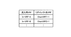
- FIG. 3 is a diagram illustrating an example of information stored in the setting information storage unit.
- FIG. 4 is a sequence diagram illustrating an example of processing by the communication system according to the first embodiment.
- FIG. 5 is a diagram for explaining the effect of the communication system according to the first embodiment.
- FIG. 6 is a diagram illustrating a computer that executes a program.
- FIG. 1 is a diagram showing an example of the configuration of a communication system according to the first embodiment.
- the communication system 100 according to the first embodiment includes a chaining edge router 10, a chaining controller 20, a plurality of transfer source devices 30A to 30C, and a plurality of functions 40A to 40C.
- the configuration shown in FIG. 1 is merely an example, and the specific configuration and the number of devices are not particularly limited.
- the plurality of transfer source devices 30A to 30C and the plurality of functions 40A to 40C will be referred to as a transfer source device 30 and a function 40, respectively, when they are described without distinction.
- the communication system 100 controls a route to pass an arbitrary service function for each type of traffic.
- inflow VRFs In VRFs
- In VRFs are created by the number of traffic patterns to be distinguished, and control target traffics flow into different In VRFs.
- the VRF and the VLAN are used in advance, and the routes are preliminarily constructed by using the VRF, the VLAN and the bridge interface by the number of traffic patterns to be distinguished. These VRFs are called "Chain VRFs".
- the broadcast is used on the bridge interface (BridgeIF) to realize the traffic transfer to multiple ports.
- the chaining controller 20 controls the chaining edge router 10 by instructing the chaining edge router 10 to set the route of the inflow traffic.
- the chaining controller 20 uses BGP Flowspec to specify the chain VRF to which each In VRF is redirected, thereby controlling which route the inflow traffic is transferred to.
- the transfer source devices 30A to 30C are devices that transfer packets to the chaining edge router 10, respectively.
- the functions 40A to 40C are devices that execute network processing on the packet by the network service function.
- a communication path is constructed at L2 using a VLAN. That is, in the communication system 100, a route is constructed in L2 by using VRF and VLAN in advance, and a route that does not depend on the L3 header is realized.
- the transfer source device 30A transmits a packet to In VRF-A
- the transfer source device 30B transmits a packet to In VRF-B.
- a route pattern prepared in advance will be described using the example of FIG.
- the chaining edge router 10 when the chaining edge router 10 receives a packet with In VRF-A, it redirects the packet to Chain VRF 1-1. After that, the chaining router 10 transfers the packet from the Chain VRF 1-1 to the function 40A via VLAN:10 according to the route pattern. Then, the chaining edge router 10 receives the packet processed by the function 40A at the Chain VRF1-2, and notifies the packet from the Chain VRF1-2 to the BridgeIF1-2. Subsequently, the chaining edge router 10 duplicates the packet and transfers the packet to the function 40B and the function 40C using L2 broadcast on the Bridge IF1-2.
- the chaining edge router 10 redirects the packet to Chain VRF2-1 and then transmits the packet from Chain VRF2-1 to function 40C via VLAN:20 according to the route pattern. To transfer.
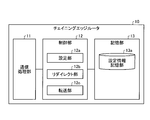
- FIG. 2 is a diagram showing an example of the configuration of the chaining edge router according to the first embodiment.
- the chaining edge router 10 has a communication processing unit 11, a control unit 12, and a storage unit 13. The processing of each unit of the chaining edge router 10 will be described below.
- the communication processing unit 11 controls communication regarding various types of information. For example, the communication processing unit 11 receives an instruction regarding setting from the chaining controller 20 and transmits/receives packets to/from the transfer source device 30 and the function 40.
- the storage unit 13 stores data and programs necessary for various processes performed by the control unit 12.
- the storage unit 13 has a setting information storage unit 13a.
- the storage unit 13 is a semiconductor memory device such as a RAM (Random Access Memory) or a flash memory (Flash Memory), or a storage device such as a hard disk or an optical disk.
- the setting information storage unit 13a stores the redirect-destination VRF in association with each inflow VRF.
- the setting information storage unit 13a includes an "inflow VRF" indicating information for uniquely identifying the In VRF and a "redirect destination VRF” indicating information for uniquely identifying the redirect destination VRF. And are stored in association with each other.
- the control unit 12 has an internal memory for storing a program defining various processing procedures and required data, and executes various processing by these.
- the control unit 12 has a setting unit 12a, a redirect unit 12b, and a transfer unit 12c.
- the control unit 12 is, for example, an electronic circuit such as a CPU (Central Processing Unit) or MPU (Micro Processing Unit), or an integrated circuit such as an ASIC (Application Specific Integrated Circuit) or an FPGA (Field Programmable Gate Array).
- the setting unit 12a sets the Chain VRF to which each inflow VRF is redirected by using BGP Flowspec. Specifically, the setting unit 12a receives the designation of the redirect destination VRF by the BGP Flowspec from the chaining controller 20, and stores the information of the designated redirect destination VRF in the setting information storage unit 13a. To explain using a specific example, the setting unit 12a determines that the inflow VRF "In VRF-A" is specified by the chaining controller 20 when "Chain VRF1-1" is specified as the redirect destination VRF. The "In VRF-A" and the redirect destination VRF "Chain VRF1-1" are stored in the setting information storage unit 13a in association with each other.
- the redirect unit 12b redirects the packet to the chain VRF corresponding to the inflow VRF when the packet is received via any of the inflow VRFs out of the plurality of inflow VRFs provided for each route pattern. .. Specifically, when the redirect unit 12b receives a packet via the inflow VRF, the redirect unit 12b redirects the packet to the chain VRF set as the redirect destination of the inflow VRF by the setting unit 12a.
- the redirect unit 12b when the redirect unit 12b receives a packet with the inflow VRF “In VRF-A”, the redirect unit 12b refers to the setting information storage unit 13a and uses the redirect destination VRF corresponding to the inflow VRF “In VRF-A”. Redirect the packet to a certain "Chain VRF1-1".
- the transfer unit 12c transfers the packet redirected to the Chain VRF to each function 40 according to the route pattern corresponding to the chain VRF via the communication route constructed in advance using VLAN.
- the transfer unit 12c duplicates the packet, and transfers the duplicated packet to the different functions 40 by L2 broadcast via the communication path constructed at the L2 level. For example, the transfer unit 12c duplicates the packet and transfers the packet to a plurality of functions in parallel by using L2 broadcast on the Bridge IF.
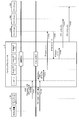
- FIG. 4 is a sequence diagram illustrating an example of processing by the communication system according to the first embodiment.
- the processing at the time of route setting and the processing at the time of traffic inflow performed in advance will be described.
- the chaining controller 20 specifies a redirect destination VRF by BGP Flowspec to the chaining edge router 10 as a process at the time of setting a route (step S101).
- the chaining controller 20 specifies “Chain VRF1-1” as the redirect destination VRF of the inflow VRF “In VRF-A”.
- the transfer source device 30 transfers the traffic to the inflow VRF “In VRF-A” (step S102)
- the In VRF-A redirects the packet to the set Chain VRF 1-1 (step S103).
- the chaining edge router 10 transfers the packet from the Chain VRF 1-1 to the function 40A as the default route (step S104). Then, the chaining edge router 10 receives the packet processed by the function 40A by the Chain VRF1-2 (step S105), and notifies the packet from the Chain VRF1-2 to the BridgeIF1-2 (step S106).
- the chaining edge router 10 duplicates the packet and transfers the packet to the function 40B and the function 40C using L2 broadcast on the Bridge IF1-2 (steps S107 and S108).
- the chaining edge router 10 transmits a packet via any of the inflow VRFs among the plurality of inflow VRFs provided for each route pattern. When received, the packet is redirected to the chain VRF corresponding to the inflow VRF. Then, the chaining edge router 10 transfers the packet redirected to the chain VRF to the function according to the route pattern corresponding to the chain VRF via the communication route constructed in advance using the VLAN.
- the communication system 100 it is possible to reduce the number of route advertisements by preparing a route pattern in advance and distributing the routes only at the time of inflow.
- the communication system 100 it is possible to duplicate traffic to branch a route and transfer the traffic in parallel to a plurality of functions. Further, in the communication system 100, since the intermediate route is set at the L2 level, it is possible to identify each original traffic even if the IP information after passing the function overlaps in different traffic.
- FIG. 5 is a diagram for explaining the effect of the communication system according to the first embodiment.
- the communication system 100 according to the first embodiment can be realized only by a standard IP Routing mechanism. That is, in the communication system 100, it is possible to control the route of the traffic without adding a unique header to the packet as in the conventional NSH method.
- the route advertisement destination for each inflow traffic is only In VRF, and it is possible to reduce the number of route advertisements compared to the conventional Flow chain method. .. Further, in the communication system 100, it is possible to identify a VLAN for each source traffic even if IP information after processing by a function (SF: Service Function) is duplicated.
- SF Service Function
- each component of each device shown in the drawings is functionally conceptual and does not necessarily have to be physically configured as shown. That is, the specific form of distribution/integration of each device is not limited to that shown in the figure, and all or part of the device may be functionally or physically distributed/arranged in arbitrary units according to various loads and usage conditions. It can be integrated and configured. Further, each processing function performed by each device may be implemented entirely or in part by a CPU and a program that is analyzed and executed by the CPU, or may be implemented as hardware by a wired logic.
- program Further, it is also possible to create a program described in a computer-executable language for the processing executed by each device described in the above embodiment. For example, it is possible to create a program described in a computer-executable language for the processing executed by each device in the communication system according to the embodiment. In this case, the computer executes the program to obtain the same effect as that of the above embodiment.
- a computer that executes a program will be described.
- FIG. 6 is a diagram showing a computer that executes a program.
- the computer 1000 has, for example, a memory 1010 and a CPU 1020.
- the computer 1000 also has a hard disk drive interface 1030, a disk drive interface 1040, a serial port interface 1050, a video adapter 1060, and a network interface 1070. These units are connected by a bus 1080.
- the memory 1010 includes a ROM (Read Only Memory) 1011 and a RAM 1012.
- the ROM 1011 stores, for example, a boot program such as BIOS (Basic Input Output System).
- BIOS Basic Input Output System
- the hard disk drive interface 1030 is connected to the hard disk drive 1090.
- the disk drive interface 1040 is connected to the disk drive 1100.
- a removable storage medium such as a magnetic disk or an optical disk is inserted into the disk drive 1100.
- the serial port interface 1050 is connected to, for example, the mouse 1051 and the keyboard 1052.
- the video adapter 1060 is connected to the display 1061, for example.
- the hard disk drive 1090 stores, for example, an OS 1091, an application program 1092, a program module 1093, and program data 1094. That is, the program defining each process of each device is implemented as a program module 1093 in which a code executable by a computer is described.
- the program module 1093 is stored in the hard disk drive 1090, for example.
- a program module 1093 for executing the same processing as the functional configuration of the device is stored in the hard disk drive 1090.
- the hard disk drive 1090 may be replaced with an SSD (Solid State Drive).
- the data used in the processing of the above-described embodiment is stored as program data 1094 in, for example, the memory 1010 or the hard disk drive 1090. Then, the CPU 1020 reads the program module 1093 and the program data 1094 stored in the memory 1010 or the hard disk drive 1090 into the RAM 1012 as necessary and executes them.
- the program module 1093 and the program data 1094 are not limited to being stored in the hard disk drive 1090, but may be stored in, for example, a removable storage medium and read by the CPU 1020 via the disk drive 1100 or the like. Alternatively, the program module 1093 and the program data 1094 may be stored in another computer connected via a network or WAN. Then, the program module 1093 and the program data 1094 may be read by the CPU 1020 from another computer via the network interface 1070.
- chaining edge router 11 communication processing unit 12 control unit 12a setting unit 12b redirecting unit 12c transfer unit 13 storage unit 13a setting information storage unit 20 chaining controller 30A to 30C transfer source device 40A to 40C function 100 communication system
Landscapes
- Engineering & Computer Science (AREA)
- Computer Networks & Wireless Communication (AREA)
- Signal Processing (AREA)
- Computer Security & Cryptography (AREA)
- Data Exchanges In Wide-Area Networks (AREA)
Abstract
チェイニングエッジルータ(10)が、経路パターンごとに設けられた複数の流入用VRFのうち、いずれかの流入用VRFを介してパケットを受信した場合に、該流入用VRFに対応するチェインVRFにパケットをリダイレクトする。そして、チェイニングエッジルータ(10)が、チェインVRFにリダイレクトされたパケットを、該チェインVRFに対応する経路パターンに従って、あらかじめVLANを用いて構築された通信経路を介して、ファンクションに転送する。
Description
本発明は、通信システムおよび通信方法に関する。
近年、ネットワーク上でトラヒックの種類ごとに任意のサービスファンクションを通過するよう経路を制御するサービスチェイニングの技術が知られている。このようなサービスチェイニングを実現するためのService Function Chainingというアーキテクチャや、独自ヘッダをパケットに付与することでこれを実現するNSH(Network Service Header)という方式が存在する。また、独自ヘッダを用いず既存のIPルーティングを用いたサービスチェイニング方式として、Flow chainという方式が存在する。
"Practical Service Chaining based on IP Routing"、[online]、[平成31年1月30日検索]、インターネット<https://dl.acm.org/citation.cfm?id=3289170>
"サービスチェイニングについてIETF新方式での6社相互接続を世界に先駆けて実証"、[online]、[平成31年1月30日検索]、インターネット<http://www.ntt.co.jp/news2015/1502/150212a.html>
しかしながら、従来の技術では、流入トラヒック変化に伴い通過する全VRFへの経路広告が必要なため、スケール性に制約があるという課題があった。例えば、Flow chainの方式では、流入トラヒック変化に伴い通過する全VRFへの経路広告が必要なため、スケール性に制約がある。一方、例えば、従来のNSHでは、パケットに独自ヘッダを付与するため、転送装置が対応していなければ使用できない。なお、NSHの方式では、パケットに独自ヘッダを付与するため、転送装置が対応していなければ使用できなかった。
上述した課題を解決し、目的を達成するために、本発明の通信システムは、経路パターンごとに設けられた複数の流入用VRFのうち、いずれかの流入用VRFを介してパケットを受信した場合に、該流入用VRFに対応するチェインVRFに前記パケットをリダイレクトするリダイレクト部と、前記リダイレクト部によってチェインVRFにリダイレクトされたパケットを、該チェインVRFに対応する経路パターンに従って、あらかじめVLANを用いて構築された通信経路を介して、ファンクションに転送する転送部とを有することを特徴とする。
また、本発明の通信方法は、通信システムで実行される通信方法であって、経路パターンごとに設けられた複数の流入用VRFのうち、いずれかの流入用VRFを介してパケットを受信した場合に、該流入用VRFに対応するチェインVRFに前記パケットをリダイレクトするリダイレクト工程と、前記リダイレクト工程によってチェインVRFにリダイレクトされたパケットを、該チェインVRFに対応する経路パターンに従って、あらかじめVLANを用いて構築された通信経路を介して、ファンクションに転送する転送工程とを含むことを特徴とする。
本発明によれば、あらかじめ経路パターンを用意しておき流入時にのみ経路を振り分けることにより、経路広告数を低減できるという効果を奏する。
以下に、本願に係る通信システムおよび通信方法の実施の形態を図面に基づいて詳細に説明する。なお、この実施の形態により本願に係る通信システムおよび通信方法が限定されるものではない。
[第一の実施の形態]
以下の実施の形態では、第一の実施の形態に係る通信システムの構成、通信システムにおける処理の流れを順に説明し、最後に第一の実施の形態による効果を説明する。
以下の実施の形態では、第一の実施の形態に係る通信システムの構成、通信システムにおける処理の流れを順に説明し、最後に第一の実施の形態による効果を説明する。
[通信システムの構成]
まず、図1を用いて、第一の実施の形態に係る通信システム100の概要について説明する。図1は、第一の実施の形態に係る通信システムの構成の一例を示す図である。第一の実施の形態に係る通信システム100は、チェイニングエッジルータ10、チェイニングコントローラ20、複数の転送元装置30A~30Cおよび複数のファンクション40A~40Cを有する。なお、図1に示す構成は一例にすぎず、具体的な構成や各装置の数は特に限定されない。また、複数の転送元装置30A~30Cおよび複数のファンクション40A~40Cについて、特に区別なく説明する場合には、転送元装置30、ファンクション40と記載する。
まず、図1を用いて、第一の実施の形態に係る通信システム100の概要について説明する。図1は、第一の実施の形態に係る通信システムの構成の一例を示す図である。第一の実施の形態に係る通信システム100は、チェイニングエッジルータ10、チェイニングコントローラ20、複数の転送元装置30A~30Cおよび複数のファンクション40A~40Cを有する。なお、図1に示す構成は一例にすぎず、具体的な構成や各装置の数は特に限定されない。また、複数の転送元装置30A~30Cおよび複数のファンクション40A~40Cについて、特に区別なく説明する場合には、転送元装置30、ファンクション40と記載する。
第一の実施の形態に係る通信システム100は、トラヒックの種類ごとに任意のサービスファンクションを通過するよう経路を制御する。チェイニングエッジルータ10では、区別したいトラヒックパターンの数だけ流入用VRF(In VRF)が作成され、制御対象トラヒックはそれぞれ異なるIn VRFへ流入される。
また、チェイニングエッジルータ10では、あらかじめVRFおよびVLANを用いて、区別したいトラヒックパターンの数だけVRFとVLANおよびブリッジインタフェースを用いて経路があらかじめ構築される。これらのVRFを「Chain VRF」とする。
また、チェイニングエッジルータ10では、経路途中でトラヒックを複製する際は、ブリッジインタフェース(BridgeIF)上でブロードキャストを用いることで複数ポートへのトラヒック転送を実現する。
チェイニングコントローラ20は、チェイニングエッジルータ10に対して流入トラヒックの経路に関する設定を指示することで、チェイニングエッジルータ10を制御する。例えば、チェイニングコントローラ20は、BGP Flowspecを用いて、各In VRFのリダイレクト先のチェインVRFを指定することで、流入トラヒックをどの経路に転送するかを制御する。
転送元装置30A~30Cは、それぞれチェイニングエッジルータ10に対してパケットを転送する装置である。ファンクション40A~40Cは、パケットに対してネットワークサービス機能にてネットワーク処理を実行する装置である。チェイニングエッジルータ10のVRFと各ファンクション40A~40Cとは、それぞれVLANを用いてL2にて通信経路が構築されている。つまり、通信システム100では、あらかじめVRFおよびVLANを用いて、L2にて経路を構築しておき、L3ヘッダに依存しない経路を実現している。
また、図1の例では、転送元装置30Aは、In VRF-Aにパケットを送信し、転送元装置30Bは、In VRF-Bにパケットを送信する。ここで、図1の例を用いて、あらかじめ用意された経路パターンについて説明する。
図1に例示するように、チェイニングエッジルータ10は、In VRF-Aでパケットを受信した場合には、Chain VRF1-1にパケットをリダイレクトする。その後、チェイニングルータ10は、経路パターンに従って、Chain VRF1-1からファンクション40AへVLAN:10経由でパケットを転送する。そして、チェイニングエッジルータ10は、ファンクション40Aで処理されたパケットをChain VRF1-2で受信し、Chain VRF1-2からBridgeIF1-2にパケットを通知する。続いて、チェイニングエッジルータ10は、パケットを複製し、BridgeIF1-2上でL2ブロードキャストを用いて、ファンクション40Bおよびファンクション40Cへパケットを転送する。
また、チェイニングエッジルータ10は、In VRF-Bでパケットを受信した場合には、Chain VRF2-1にパケットをリダイレクトした後、経路パターンに従ってChain VRF2-1からファンクション40CへVLAN:20経由でパケットを転送する。
このように、第一の実施の形態に係る通信システム100では、あらかじめ経路パターンを用意しておき流入時にのみ経路を振り分けることにより、経路広告数を低減することが可能である。また、チェイニングエッジルータ10では、途中経路をL2レベルで設定しているため、別々のトラヒックにおいてファンクション通過後のIP情報が重複しても元トラヒックごとに識別することができる。
[チェイニングエッジルータの構成]
次に、図2を用いて、チェイニングエッジルータ10の構成を説明する。図2は、第一の実施の形態に係るチェイニングエッジルータの構成の一例を示す図である。図2に示すように、このチェイニングエッジルータ10は、通信処理部11、制御部12および記憶部13を有する。以下にチェイニングエッジルータ10が有する各部の処理を説明する。
次に、図2を用いて、チェイニングエッジルータ10の構成を説明する。図2は、第一の実施の形態に係るチェイニングエッジルータの構成の一例を示す図である。図2に示すように、このチェイニングエッジルータ10は、通信処理部11、制御部12および記憶部13を有する。以下にチェイニングエッジルータ10が有する各部の処理を説明する。
通信処理部11は、各種情報に関する通信を制御する。例えば、通信処理部11は、チェイニングコントローラ20から設定に関する指示を受信したり、転送元装置30およびファンクション40との間でパケットを送受信したりする。
記憶部13は、制御部12による各種処理に必要なデータおよびプログラムを格納する。記憶部13は、設定情報記憶部13aを有する。例えば、記憶部13は、RAM(Random Access Memory)、フラッシュメモリ(Flash Memory)等の半導体メモリ素子、又は、ハードディスク、光ディスク等の記憶装置などである。
設定情報記憶部13aは、各流入用VRFに対応付けて、リダイレクト先のVRFを記憶する。例えば、設定情報記憶部13aは、図3に例示するように、In VRFを一意に識別する情報を示す「流入用VRF」と、リダイレクト先VRFを一意に識別する情報を示す「リダイレクト先VRF」とを対応付けて記憶する。
図3の例を挙げて具体的に説明すると、設定情報記憶部13aは、例えば、流入用VRF「In VRF-A」と、リダイレクト先VRF「Chain VRF1-1」とを対応付けて記憶する。これは、チェイニングエッジルータ10が、In VRF-Aでパケットを受信した場合には、Chain VRF1-1にパケットをリダイレクトすることを意味する。また、設定情報記憶部13aに記憶された情報は、チェイニングコントローラ20によって登録された情報であり、チェイニングコントローラ20の指示に応じて追加、変更、削除される。
制御部12は、各種の処理手順などを規定したプログラムおよび所要データを格納するための内部メモリを有し、これらによって種々の処理を実行する。制御部12は、設定部12a、リダイレクト部12bおよび転送部12cを有する。ここで、制御部12は、例えば、CPU(Central Processing Unit)やMPU(Micro Processing Unit)などの電子回路やASIC(Application Specific Integrated Circuit)やFPGA(Field Programmable Gate Array)などの集積回路である。
設定部12aは、BGP Flowspecを用いて、各流入用VRFのリダイレクト先のChain VRFを設定する。具体的には、設定部12aは、BGP Flowspecによるリダイレクト先VRFの指定をチェイニングコントローラ20から受け付け、指定されたリダイレクト先VRFの情報を設定情報記憶部13aに格納する。具体例を挙げて説明すると、設定部12aは、チェイニングコントローラ20から流入用VRF「In VRF-A」について、リダイレクト先VRFとして「Chain VRF1-1」が指定された場合には、流入用VRF「In VRF-A」とリダイレクト先VRF「Chain VRF1-1」とを対応付けて設定情報記憶部13aに格納する。
リダイレクト部12bは、経路パターンごとに設けられた複数の流入用VRFのうち、いずれかの流入用VRFを介してパケットを受信した場合に、該流入用VRFに対応するチェインVRFにパケットをリダイレクトする。具体的には、リダイレクト部12bは、流入用VRFを介してパケットを受信した場合に、設定部12aによって流入用VRFのリダイレクト先として設定されたチェインVRFにパケットをリダイレクトする。
例えば、リダイレクト部12bは、流入用VRF「In VRF-A」でパケットを受信した場合には、設定情報記憶部13aを参照し、流入用VRF「In VRF-A」に対応するリダイレクト先VRFである「Chain VRF1-1」にパケットをリダイレクトする。
転送部12cは、Chain VRFにリダイレクトされたパケットを、該チェインVRFに対応する経路パターンに従って、あらかじめVLANを用いて構築された通信経路を介して、各ファンクション40に転送する。
また、転送部12cは、パケットを複製し、複製したパケットを、L2レベルで構築された通信経路を介して、L2ブロードキャストでそれぞれ異なるファンクション40に転送する。例えば、転送部12cは、パケットを複製し、BridgeIF上でL2ブロードキャストを用いて、複数のファンクションにパケットを並列に転送する。
[通信システムの処理の流れ]
次に、図4を用いて、第一の実施の形態に係る通信システム100の処理の流れを説明する。図4は、第一の実施の形態に係る通信システムによる処理の一例を説明するシーケンス図である。図4の例では、あらかじめ行われる経路設定時の処理と、トラヒック流入時の処理とを説明する。
次に、図4を用いて、第一の実施の形態に係る通信システム100の処理の流れを説明する。図4は、第一の実施の形態に係る通信システムによる処理の一例を説明するシーケンス図である。図4の例では、あらかじめ行われる経路設定時の処理と、トラヒック流入時の処理とを説明する。
図4に例示するように、チェイニングコントローラ20は、経路設定時の処理として、チェイニングエッジルータ10に対して、BGP Flowspecによるリダイレクト先VRFを指定する(ステップS101)。図4の例では、チェイニングコントローラ20は、流入用VRF「In VRF-A」のリダイレクト先VRFとして「Chain VRF1-1」を指定する。
そして、転送元装置30がトラヒックを流入用VRF「In VRF-A」へ転送すると(ステップS102)、In VRF-Aは、設定されたChain VRF1-1にパケットをリダイレクトする(ステップS103)。
そして、チェイニングエッジルータ10は、デフォルトルートとして、Chain VRF1-1からファンクション40Aへパケットを転送する(ステップS104)。そして、チェイニングエッジルータ10は、ファンクション40Aで処理されたパケットをChain VRF1-2で受信し(ステップS105)、Chain VRF1-2からBridgeIF1-2にパケットを通知する(ステップS106)。
続いて、チェイニングエッジルータ10は、パケットを複製し、BridgeIF1-2上でL2ブロードキャストを用いて、ファンクション40Bおよびファンクション40Cへパケットを転送する(ステップS107、S108)。
[第一の実施の形態の効果]
このように、第一の実施の形態に係る通信システム100では、チェイニングエッジルータ10が、経路パターンごとに設けられた複数の流入用VRFのうち、いずれかの流入用VRFを介してパケットを受信した場合に、該流入用VRFに対応するチェインVRFにパケットをリダイレクトする。そして、チェイニングエッジルータ10が、チェインVRFにリダイレクトされたパケットを、該チェインVRFに対応する経路パターンに従って、あらかじめVLANを用いて構築された通信経路を介して、ファンクションに転送する。
このように、第一の実施の形態に係る通信システム100では、チェイニングエッジルータ10が、経路パターンごとに設けられた複数の流入用VRFのうち、いずれかの流入用VRFを介してパケットを受信した場合に、該流入用VRFに対応するチェインVRFにパケットをリダイレクトする。そして、チェイニングエッジルータ10が、チェインVRFにリダイレクトされたパケットを、該チェインVRFに対応する経路パターンに従って、あらかじめVLANを用いて構築された通信経路を介して、ファンクションに転送する。
このため、第一の実施の形態に係る通信システム100では、あらかじめ経路パターンを用意しておき流入時にのみ経路を振り分けることにより、経路広告数を低減することが可能である。
また、第一の実施の形態に係る通信システム100では、トラヒックを途中で複製して経路を分岐させ、複数ファンクションに並列に転送することが可能である。さらに、通信システム100では、途中経路をL2レベルで設定するため、別々のトラヒックにおいてファンクション通過後のIP情報が重複しても元トラヒックごとに識別することが可能である。
ここで、図5を用いて、第一の実施の形態に係る通信システム100の効果を説明する。図5は、第一の実施の形態に係る通信システムの効果を説明する図である。図5に例示するように、第一の実施の形態に係る通信システム100では、標準的なIP Routingの仕組のみで実現することができる。つまり、通信システム100では、従来のNSHの手法の方式のようにパケットに独自ヘッダを付与することなく、トラヒックの経路制御を行うことが可能である。
また、図5に例示するように、通信システム100では、流入トラヒックごとの経路広告先はIn VRFのみであり、従来のFlow chainの方式と比べて、経路広告数を低減することが可能である。また、通信システム100では、ファンクション(SF:Service Function)による処理後のIP情報が重複しても元トラヒックごとにVLANを識別することが可能である。
[システム構成等]
また、図示した各装置の各構成要素は機能概念的なものであり、必ずしも物理的に図示の如く構成されていることを要しない。すなわち、各装置の分散・統合の具体的形態は図示のものに限られず、その全部または一部を、各種の負荷や使用状況などに応じて、任意の単位で機能的または物理的に分散・統合して構成することができる。さらに、各装置にて行われる各処理機能は、その全部または任意の一部が、CPUおよび当該CPUにて解析実行されるプログラムにて実現され、あるいは、ワイヤードロジックによるハードウェアとして実現され得る。
また、図示した各装置の各構成要素は機能概念的なものであり、必ずしも物理的に図示の如く構成されていることを要しない。すなわち、各装置の分散・統合の具体的形態は図示のものに限られず、その全部または一部を、各種の負荷や使用状況などに応じて、任意の単位で機能的または物理的に分散・統合して構成することができる。さらに、各装置にて行われる各処理機能は、その全部または任意の一部が、CPUおよび当該CPUにて解析実行されるプログラムにて実現され、あるいは、ワイヤードロジックによるハードウェアとして実現され得る。
また、本実施の形態において説明した各処理のうち、自動的に行われるものとして説明した処理の全部または一部を手動的に行うこともでき、あるいは、手動的におこなわれるものとして説明した処理の全部または一部を公知の方法で自動的に行うこともできる。この他、上記文書中や図面中で示した処理手順、制御手順、具体的名称、各種のデータやパラメータを含む情報については、特記する場合を除いて任意に変更することができる。
[プログラム]
また、上記実施形態において説明した各装置が実行する処理について、コンピュータが実行可能な言語で記述したプログラムを作成することもできる。例えば、実施形態に係る通信システムにおける各装置が実行する処理について、コンピュータが実行可能な言語で記述したプログラムを作成することもできる。この場合、コンピュータがプログラムを実行することにより、上記実施形態と同様の効果を得ることができる。以下に、プログラムを実行するコンピュータの一例を説明する。
また、上記実施形態において説明した各装置が実行する処理について、コンピュータが実行可能な言語で記述したプログラムを作成することもできる。例えば、実施形態に係る通信システムにおける各装置が実行する処理について、コンピュータが実行可能な言語で記述したプログラムを作成することもできる。この場合、コンピュータがプログラムを実行することにより、上記実施形態と同様の効果を得ることができる。以下に、プログラムを実行するコンピュータの一例を説明する。
図6は、プログラムを実行するコンピュータを示す図である。コンピュータ1000は、例えば、メモリ1010、CPU1020を有する。また、コンピュータ1000は、ハードディスクドライブインタフェース1030、ディスクドライブインタフェース1040、シリアルポートインタフェース1050、ビデオアダプタ1060、ネットワークインタフェース1070を有する。これらの各部は、バス1080によって接続される。
メモリ1010は、ROM(Read Only Memory)1011及びRAM1012を含む。ROM1011は、例えば、BIOS(Basic Input Output System)等のブートプログラムを記憶する。ハードディスクドライブインタフェース1030は、ハードディスクドライブ1090に接続される。ディスクドライブインタフェース1040は、ディスクドライブ1100に接続される。例えば磁気ディスクや光ディスク等の着脱可能な記憶媒体が、ディスクドライブ1100に挿入される。シリアルポートインタフェース1050は、例えばマウス1051、キーボード1052に接続される。ビデオアダプタ1060は、例えばディスプレイ1061に接続される。
ハードディスクドライブ1090は、例えば、OS1091、アプリケーションプログラム1092、プログラムモジュール1093、プログラムデータ1094を記憶する。すなわち各装置の各処理を規定するプログラムは、コンピュータにより実行可能なコードが記述されたプログラムモジュール1093として実装される。プログラムモジュール1093は、例えばハードディスクドライブ1090に記憶される。例えば、装置における機能構成と同様の処理を実行するためのプログラムモジュール1093が、ハードディスクドライブ1090に記憶される。なお、ハードディスクドライブ1090は、SSD(Solid State Drive)により代替されてもよい。
また、上述した実施の形態の処理で用いられるデータは、プログラムデータ1094として、例えばメモリ1010やハードディスクドライブ1090に記憶される。そして、CPU1020が、メモリ1010やハードディスクドライブ1090に記憶されたプログラムモジュール1093やプログラムデータ1094を必要に応じてRAM1012に読み出して実行する。
なお、プログラムモジュール1093やプログラムデータ1094は、ハードディスクドライブ1090に記憶される場合に限らず、例えば着脱可能な記憶媒体に記憶され、ディスクドライブ1100等を介してCPU1020によって読み出されてもよい。あるいは、プログラムモジュール1093及びプログラムデータ1094は、ネットワーク、WANを介して接続された他のコンピュータに記憶されてもよい。そして、プログラムモジュール1093及びプログラムデータ1094は、他のコンピュータから、ネットワークインタフェース1070を介してCPU1020によって読み出されてもよい。
10 チェイニングエッジルータ
11 通信処理部
12 制御部
12a 設定部
12b リダイレクト部
12c 転送部
13 記憶部
13a 設定情報記憶部
20 チェイニングコントローラ
30A~30C 転送元装置
40A~40C ファンクション
100 通信システム
11 通信処理部
12 制御部
12a 設定部
12b リダイレクト部
12c 転送部
13 記憶部
13a 設定情報記憶部
20 チェイニングコントローラ
30A~30C 転送元装置
40A~40C ファンクション
100 通信システム
Claims (4)
- 経路パターンごとに設けられた複数の流入用VRFのうち、いずれかの流入用VRFを介してパケットを受信した場合に、該流入用VRFに対応するチェインVRFに前記パケットをリダイレクトするリダイレクト部と、
前記リダイレクト部によってチェインVRFにリダイレクトされたパケットを、該チェインVRFに対応する経路パターンに従って、あらかじめVLANを用いて構築された通信経路を介して、ファンクションに転送する転送部と
を有することを特徴とする通信システム。 - BGP Flowspecを用いて、各流入用VRFのリダイレクト先のチェインVRFを設定する設定部をさらに有し、
前記リダイレクト部は、流入用VRFを介してパケットを受信した場合に、前記設定部によって前記流入用VRFのリダイレクト先として設定されたチェインVRFに前記パケットをリダイレクトすることを特徴とする請求項1に記載の通信システム。 - 前記転送部は、パケットを複製し、複製したパケットを、L2レベルで構築された通信経路を介して、L2ブロードキャストでそれぞれ異なるファンクションに転送することを特徴とする請求項1に記載の通信システム。
- 通信システムで実行される通信方法であって、
経路パターンごとに設けられた複数の流入用VRFのうち、いずれかの流入用VRFを介してパケットを受信した場合に、該流入用VRFに対応するチェインVRFに前記パケットをリダイレクトするリダイレクト工程と、
前記リダイレクト工程によってチェインVRFにリダイレクトされたパケットを、該チェインVRFに対応する経路パターンに従って、あらかじめVLANを用いて構築された通信経路を介して、ファンクションに転送する転送工程と
を含むことを特徴とする通信方法。
Priority Applications (1)
| Application Number | Priority Date | Filing Date | Title |
|---|---|---|---|
| US17/427,855 US11979255B2 (en) | 2019-02-06 | 2020-01-22 | Communication system and communication method |
Applications Claiming Priority (2)
| Application Number | Priority Date | Filing Date | Title |
|---|---|---|---|
| JP2019020122A JP7081521B2 (ja) | 2019-02-06 | 2019-02-06 | 通信システムおよび通信方法 |
| JP2019-020122 | 2019-02-06 |
Publications (1)
| Publication Number | Publication Date |
|---|---|
| WO2020162180A1 true WO2020162180A1 (ja) | 2020-08-13 |
Family
ID=71947555
Family Applications (1)
| Application Number | Title | Priority Date | Filing Date |
|---|---|---|---|
| PCT/JP2020/002140 Ceased WO2020162180A1 (ja) | 2019-02-06 | 2020-01-22 | 通信システムおよび通信方法 |
Country Status (3)
| Country | Link |
|---|---|
| US (1) | US11979255B2 (ja) |
| JP (1) | JP7081521B2 (ja) |
| WO (1) | WO2020162180A1 (ja) |
Citations (3)
| Publication number | Priority date | Publication date | Assignee | Title |
|---|---|---|---|---|
| US20100329265A1 (en) * | 2009-06-26 | 2010-12-30 | Nortel Networks Limited | Method and Apparatus for implementing L2 VPNs on an IP Network |
| US9961624B1 (en) * | 2017-02-09 | 2018-05-01 | T-Mobile Usa, Inc. | Network slice selection in wireless telecommunication networks |
| US10057162B1 (en) * | 2016-06-27 | 2018-08-21 | Amazon Technologies, Inc. | Extending Virtual Routing and Forwarding at edge of VRF-aware network |
Family Cites Families (2)
| Publication number | Priority date | Publication date | Assignee | Title |
|---|---|---|---|---|
| US9826025B2 (en) * | 2013-05-21 | 2017-11-21 | Cisco Technology, Inc. | Chaining service zones by way of route re-origination |
| US9948552B2 (en) * | 2015-04-17 | 2018-04-17 | Equinix, Inc. | Cloud-based services exchange |
-
2019
- 2019-02-06 JP JP2019020122A patent/JP7081521B2/ja active Active
-
2020
- 2020-01-22 WO PCT/JP2020/002140 patent/WO2020162180A1/ja not_active Ceased
- 2020-01-22 US US17/427,855 patent/US11979255B2/en active Active
Patent Citations (3)
| Publication number | Priority date | Publication date | Assignee | Title |
|---|---|---|---|---|
| US20100329265A1 (en) * | 2009-06-26 | 2010-12-30 | Nortel Networks Limited | Method and Apparatus for implementing L2 VPNs on an IP Network |
| US10057162B1 (en) * | 2016-06-27 | 2018-08-21 | Amazon Technologies, Inc. | Extending Virtual Routing and Forwarding at edge of VRF-aware network |
| US9961624B1 (en) * | 2017-02-09 | 2018-05-01 | T-Mobile Usa, Inc. | Network slice selection in wireless telecommunication networks |
Non-Patent Citations (1)
| Title |
|---|
| NAKAMURA RYO ET AL.: "Service chaining based on IP routing techniques in ShowNet 2018", IEICE TECHNICAL REPORT, vol. 118, no. 204, 27 August 2018 (2018-08-27), pages 91 - 96 * |
Also Published As
| Publication number | Publication date |
|---|---|
| JP7081521B2 (ja) | 2022-06-07 |
| US11979255B2 (en) | 2024-05-07 |
| JP2020127180A (ja) | 2020-08-20 |
| US20220131722A1 (en) | 2022-04-28 |
Similar Documents
| Publication | Publication Date | Title |
|---|---|---|
| US11223494B2 (en) | Service insertion for multicast traffic at boundary | |
| CN114342342B (zh) | 跨多个云的分布式服务链 | |
| CN107872392B (zh) | 分配服务功能链数据和服务功能实例数据的方法和装置 | |
| US20200293180A1 (en) | Stage upgrade of image versions on devices in a cluster | |
| US10243834B1 (en) | Interconnecting virtual networks using an ethernet virtual private network (EVPN) and virtual extensible local area network (VXLAN) based overlay network | |
| US9143444B2 (en) | Virtual link aggregation extension (VLAG+) enabled in a TRILL-based fabric network | |
| JP5610247B2 (ja) | ネットワークシステム、及びポリシー経路設定方法 | |
| US8296459B1 (en) | Custom routing decisions | |
| US9258267B1 (en) | Highly scalable data center architecture with address resolution protocol (ARP)-free servers | |
| US20130182606A1 (en) | Method and system of forming a mobile virtual network | |
| CN115191108A (zh) | 多架构云网络中的服务链 | |
| WO2019196562A1 (zh) | 报文处理方法、装置、存储介质及处理器 | |
| US11296907B2 (en) | Systems and methods for transitioning of virtualized transport networks | |
| US20190199622A1 (en) | Data packet forwarding unit in a data transmission network | |
| JP7250871B2 (ja) | 伝送パスを決定する方法およびノード | |
| US20200007440A1 (en) | Dynamic rule-based flow routing in networks | |
| Dixit et al. | Composing heterogeneous SDN controllers with flowbricks | |
| US10581738B2 (en) | Efficient inter-VLAN routing in openflow networks | |
| CN104954258A (zh) | 数据报文处理方法、装置及开放流交换机 | |
| JP2021182732A (ja) | 通信ネットワークにおける一次デスティネーションおよび二次デスティネーションを有するトラフィックのルーティング | |
| US20200280513A1 (en) | Fast receive re-convergence of multi-pod multi-destination traffic in response to local disruptions | |
| JP7081521B2 (ja) | 通信システムおよび通信方法 | |
| CN106209634A (zh) | 地址映射关系的学习方法及装置 | |
| CN118301701A (zh) | 使用边界网关协议流规范的覆盖网络切片的动态创建 | |
| EP1587263A1 (en) | Scalable BGP-edge-router architecture |
Legal Events
| Date | Code | Title | Description |
|---|---|---|---|
| 121 | Ep: the epo has been informed by wipo that ep was designated in this application |
Ref document number: 20752280 Country of ref document: EP Kind code of ref document: A1 |
|
| NENP | Non-entry into the national phase |
Ref country code: DE |
|
| 122 | Ep: pct application non-entry in european phase |
Ref document number: 20752280 Country of ref document: EP Kind code of ref document: A1 |