WO2020162165A1 - 障害通知システム、障害通知方法、障害通知装置および障害通知プログラム - Google Patents
障害通知システム、障害通知方法、障害通知装置および障害通知プログラム Download PDFInfo
- Publication number
- WO2020162165A1 WO2020162165A1 PCT/JP2020/002013 JP2020002013W WO2020162165A1 WO 2020162165 A1 WO2020162165 A1 WO 2020162165A1 JP 2020002013 W JP2020002013 W JP 2020002013W WO 2020162165 A1 WO2020162165 A1 WO 2020162165A1
- Authority
- WO
- WIPO (PCT)
- Prior art keywords
- logical configuration
- hardware
- failure
- unit
- processing unit
- Prior art date
- Legal status (The legal status is an assumption and is not a legal conclusion. Google has not performed a legal analysis and makes no representation as to the accuracy of the status listed.)
- Ceased
Links
Images



Classifications
-
- H—ELECTRICITY
- H04—ELECTRIC COMMUNICATION TECHNIQUE
- H04L—TRANSMISSION OF DIGITAL INFORMATION, e.g. TELEGRAPHIC COMMUNICATION
- H04L41/00—Arrangements for maintenance, administration or management of data switching networks, e.g. of packet switching networks
- H04L41/08—Configuration management of networks or network elements
- H04L41/0803—Configuration setting
-
- G—PHYSICS
- G06—COMPUTING OR CALCULATING; COUNTING
- G06F—ELECTRIC DIGITAL DATA PROCESSING
- G06F11/00—Error detection; Error correction; Monitoring
- G06F11/07—Responding to the occurrence of a fault, e.g. fault tolerance
- G06F11/0703—Error or fault processing not based on redundancy, i.e. by taking additional measures to deal with the error or fault not making use of redundancy in operation, in hardware, or in data representation
- G06F11/0706—Error or fault processing not based on redundancy, i.e. by taking additional measures to deal with the error or fault not making use of redundancy in operation, in hardware, or in data representation the processing taking place on a specific hardware platform or in a specific software environment
- G06F11/0712—Error or fault processing not based on redundancy, i.e. by taking additional measures to deal with the error or fault not making use of redundancy in operation, in hardware, or in data representation the processing taking place on a specific hardware platform or in a specific software environment in a virtual computing platform, e.g. logically partitioned systems
-
- H—ELECTRICITY
- H04—ELECTRIC COMMUNICATION TECHNIQUE
- H04L—TRANSMISSION OF DIGITAL INFORMATION, e.g. TELEGRAPHIC COMMUNICATION
- H04L41/00—Arrangements for maintenance, administration or management of data switching networks, e.g. of packet switching networks
- H04L41/06—Management of faults, events, alarms or notifications
- H04L41/0631—Management of faults, events, alarms or notifications using root cause analysis; using analysis of correlation between notifications, alarms or events based on decision criteria, e.g. hierarchy, tree or time analysis
- H04L41/0645—Management of faults, events, alarms or notifications using root cause analysis; using analysis of correlation between notifications, alarms or events based on decision criteria, e.g. hierarchy, tree or time analysis by additionally acting on or stimulating the network after receiving notifications
-
- H—ELECTRICITY
- H04—ELECTRIC COMMUNICATION TECHNIQUE
- H04L—TRANSMISSION OF DIGITAL INFORMATION, e.g. TELEGRAPHIC COMMUNICATION
- H04L41/00—Arrangements for maintenance, administration or management of data switching networks, e.g. of packet switching networks
- H04L41/06—Management of faults, events, alarms or notifications
- H04L41/0631—Management of faults, events, alarms or notifications using root cause analysis; using analysis of correlation between notifications, alarms or events based on decision criteria, e.g. hierarchy, tree or time analysis
- H04L41/065—Management of faults, events, alarms or notifications using root cause analysis; using analysis of correlation between notifications, alarms or events based on decision criteria, e.g. hierarchy, tree or time analysis involving logical or physical relationship, e.g. grouping and hierarchies
-
- H—ELECTRICITY
- H04—ELECTRIC COMMUNICATION TECHNIQUE
- H04L—TRANSMISSION OF DIGITAL INFORMATION, e.g. TELEGRAPHIC COMMUNICATION
- H04L41/00—Arrangements for maintenance, administration or management of data switching networks, e.g. of packet switching networks
- H04L41/06—Management of faults, events, alarms or notifications
- H04L41/0654—Management of faults, events, alarms or notifications using network fault recovery
- H04L41/0659—Management of faults, events, alarms or notifications using network fault recovery by isolating or reconfiguring faulty entities
- H04L41/0661—Management of faults, events, alarms or notifications using network fault recovery by isolating or reconfiguring faulty entities by reconfiguring faulty entities
-
- H—ELECTRICITY
- H04—ELECTRIC COMMUNICATION TECHNIQUE
- H04L—TRANSMISSION OF DIGITAL INFORMATION, e.g. TELEGRAPHIC COMMUNICATION
- H04L41/00—Arrangements for maintenance, administration or management of data switching networks, e.g. of packet switching networks
- H04L41/08—Configuration management of networks or network elements
- H04L41/0803—Configuration setting
- H04L41/0813—Configuration setting characterised by the conditions triggering a change of settings
- H04L41/0816—Configuration setting characterised by the conditions triggering a change of settings the condition being an adaptation, e.g. in response to network events
-
- H—ELECTRICITY
- H04—ELECTRIC COMMUNICATION TECHNIQUE
- H04L—TRANSMISSION OF DIGITAL INFORMATION, e.g. TELEGRAPHIC COMMUNICATION
- H04L41/00—Arrangements for maintenance, administration or management of data switching networks, e.g. of packet switching networks
- H04L41/08—Configuration management of networks or network elements
- H04L41/0895—Configuration of virtualised networks or elements, e.g. virtualised network function or OpenFlow elements
-
- H—ELECTRICITY
- H04—ELECTRIC COMMUNICATION TECHNIQUE
- H04L—TRANSMISSION OF DIGITAL INFORMATION, e.g. TELEGRAPHIC COMMUNICATION
- H04L41/00—Arrangements for maintenance, administration or management of data switching networks, e.g. of packet switching networks
- H04L41/12—Discovery or management of network topologies
- H04L41/122—Discovery or management of network topologies of virtualised topologies, e.g. software-defined networks [SDN] or network function virtualisation [NFV]
-
- H—ELECTRICITY
- H04—ELECTRIC COMMUNICATION TECHNIQUE
- H04L—TRANSMISSION OF DIGITAL INFORMATION, e.g. TELEGRAPHIC COMMUNICATION
- H04L41/00—Arrangements for maintenance, administration or management of data switching networks, e.g. of packet switching networks
- H04L41/40—Arrangements for maintenance, administration or management of data switching networks, e.g. of packet switching networks using virtualisation of network functions or resources, e.g. SDN or NFV entities
-
- H—ELECTRICITY
- H04—ELECTRIC COMMUNICATION TECHNIQUE
- H04L—TRANSMISSION OF DIGITAL INFORMATION, e.g. TELEGRAPHIC COMMUNICATION
- H04L43/00—Arrangements for monitoring or testing data switching networks
- H04L43/08—Monitoring or testing based on specific metrics, e.g. QoS, energy consumption or environmental parameters
- H04L43/0805—Monitoring or testing based on specific metrics, e.g. QoS, energy consumption or environmental parameters by checking availability
- H04L43/0817—Monitoring or testing based on specific metrics, e.g. QoS, energy consumption or environmental parameters by checking availability by checking functioning
-
- H—ELECTRICITY
- H04—ELECTRIC COMMUNICATION TECHNIQUE
- H04L—TRANSMISSION OF DIGITAL INFORMATION, e.g. TELEGRAPHIC COMMUNICATION
- H04L43/00—Arrangements for monitoring or testing data switching networks
- H04L43/08—Monitoring or testing based on specific metrics, e.g. QoS, energy consumption or environmental parameters
- H04L43/0805—Monitoring or testing based on specific metrics, e.g. QoS, energy consumption or environmental parameters by checking availability
- H04L43/0811—Monitoring or testing based on specific metrics, e.g. QoS, energy consumption or environmental parameters by checking availability by checking connectivity
Definitions
- the present invention provides a logical configuration providing unit that provides a logical configuration in which a plurality of hardware is virtualized, a processing unit that uses the logical configuration provided by the logical configuration providing unit, and a failure of the logical configuration providing unit to the processing unit.
- the present invention relates to a failure notification system including a failure notification unit for notifying, a failure notification method used in the failure notification system, a failure notification device, and a failure notification program.
- NFV Network Functions Virtualization
- NFV Network Functions Virtualization
- hardware may have an ACT/SBY system switching function.
- the middleware operating on the hardware has a failure control logic that detects a failure of the hardware and switches to another system when the currently operating system is difficult to continue operating.
- Non-Patent Document 1 As a method of detecting a failure, there is a method of confirming the life or death of hardware by the presence or absence of a response to a PING command (for example, refer to Non-Patent Document 1), and a method of monitoring the normality of the disk by reading/writing the disk. ..
- ManageEngine "Alive monitoring (ping monitoring)/Availability monitoring”, [online], [January 25, 2019 search], Internet ⁇ URL: https://www.manageengine.jp/products/OpManager/availability-monitoring .html ⁇
- Virtual machines understand the logical configuration but cannot understand the hardware configuration of NFV, so it is not possible to confirm each hardware failure.
- an object of the present invention is to provide a fault notification system, a fault notification method, a fault notification device, and a fault notification capable of appropriately grasping a fault in a logical configuration in a processing unit that uses a logical configuration in which a plurality of hardware is virtualized. To provide a program.
- the first feature of the present invention is to provide a logical configuration providing unit that provides a logical configuration in which a plurality of hardware is virtualized, and a process that uses the logical configuration provided by the logical configuration providing unit.
- the present invention relates to a failure notification system including a unit and a failure notification unit that notifies a failure of the logical configuration providing unit to the processing unit.
- the failure notification unit includes a hardware identifier, a storage device that stores hardware configuration data that associates an identifier of a logical configuration corresponding to the hardware, and When a failure is detected, the hardware configuration data indicates a failure in the logical configuration identifying unit that identifies the logical configuration corresponding to the hardware in which the failure is detected, and in the processing unit, the logical configuration identified by the logical configuration identifying unit. It has a notification unit for notifying that it has occurred.
- the storage device further stores logical configuration topology data indicating the connection state of the logical configuration, logical configuration identifiers, and redundant type data that associates the redundant types of the logical configurations with each other.
- the notifying unit may further notify the specified influence content by referring to the data and the redundancy type data to specify the logical configuration affected by the hardware in which the failure is detected and the influence content thereof.
- the storage device further stores processing unit data that associates the identifier of the logical configuration with the identifier of the processing unit that uses the logical configuration, and the notification unit uses the logical configuration that is specified by the logical configuration specifying unit. May be notified that a failure has occurred in the logical configuration.
- a second feature of the present invention is to provide a logical configuration providing unit that provides a logical configuration in which a plurality of hardware is virtualized, a processing unit that uses the logical configuration provided by the logical configuration providing unit, and a logical configuration providing unit.
- the present invention relates to a failure notification method used in a failure notification system including a failure notification unit that notifies a processing unit of a failure.
- a fault notifying method comprises a step in which a computer stores in a storage device hardware configuration data that associates a hardware identifier with an identifier of a logical configuration corresponding to the hardware; However, when a hardware failure is detected, the step of specifying the logical configuration corresponding to the hardware in which the failure is detected from the hardware configuration data and the logic specified by the computer in the specifying step in the processing unit. It comprises the step of notifying that a configuration has failed.
- a third feature of the present invention is to provide a logical configuration providing unit that provides a logical configuration in which a plurality of hardware is virtualized, a processing unit that uses the logical configuration provided by the logical configuration providing unit, and a logical configuration providing unit.
- the present invention relates to a failure notification device that functions as a failure notification unit in a failure notification system that includes a failure notification unit that notifies a processing unit of a failure.
- a failure notification device that detects a hardware failure, a storage device that stores hardware configuration data that associates an identifier of a logical configuration corresponding to the hardware with a storage device that stores the hardware configuration data.
- a failure occurs in the logical configuration identifying unit that identifies the logical configuration corresponding to the hardware in which the failure is detected, and the processing unit that the logical configuration identified by the logical configuration identifying unit has failed.
- a notification unit for notifying is provided.
- a fourth feature of the present invention relates to a fault notification program for causing a computer to function as the fault notification device according to the third feature of the present invention.
- a failure notification system capable of appropriately grasping a failure of a logical configuration in a processing unit using a logical configuration in which a number of hardware is virtualized.
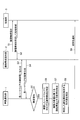
- FIG. 3 is a diagram illustrating a hardware configuration and a functional block of a failure notification unit according to the embodiment of the present invention. It is a figure explaining an example of the data structure of hardware composition data. It is a figure explaining the logic composition and hardware composition of a logic composition providing part. It is a figure explaining an example of the data structure of redundancy type data. It is a figure explaining an example of the data structure of processing part data. It is a sequence diagram explaining the process of the failure notification system which concerns on embodiment of this invention.
- the fault notification system 5 is a system in which a plurality of hardware is virtualized.
- the failure notification system 5 includes a failure notification unit 1, a logical configuration providing unit 2, a first processing unit 3a, a second processing unit 3b, and a third processing unit 3c.
- the processing unit 3a, the second processing unit 3b, and the third processing unit 3c are not particularly distinguished, they may be simply referred to as the processing unit 3.
- the fault notifying unit 1 accesses each hardware of the logical configuration providing unit 2 and notifies the processing unit 3 of the fault of each hardware of the logical configuration providing unit 2.
- the logical configuration providing unit 2 provides a logical configuration in which a plurality of hardware is virtualized.
- the logical configuration providing unit 2 provides a logical configuration from a plurality of hardware such as a processing device, a storage device, a communication control device, and a communication link.
- the processing unit 3 is an execution unit that executes an application program and uses the logical configuration provided by the logical configuration providing unit 2.
- the logical configuration providing unit 2 includes a logical configuration unit 2a and a hardware configuration unit 2b.
- the logical configuration unit 2a is a logical configuration provided by the logical configuration providing unit 2 and includes CPU resources, memory resources, disk resources, network resources, and the like.
- the hardware configuration unit 2b is physical hardware that is the actual state of each resource of the logical configuration unit 2a, and includes physical hardware including a disk, a CPU memory, a NIC, a storage (storage device), a communication control device, a network. Such as a cable.
- the logical configuration providing unit 2 allocates hardware to the resource designated by the processing unit 3 and uses it for the processing of the processing unit 3. Further, the logical configuration providing unit 2 increases or decreases the hardware assigned to the resource designated by the processing unit 3 to appropriately allocate the resources necessary for the processing of the processing unit 3 without changing the processing of the processing unit 3. You can Further, since the hardware configuration is hidden in the processing unit 3, even if the hardware is replaced due to a failure or the like, the processing unit 3 can smoothly perform the processing regardless of the replacement of the hardware.
- fault notification device A fault notification unit (fault notification device) 1 according to the embodiment of the present invention will be described with reference to FIG.
- the fault notifying unit 1 can be connected to each hardware of the logical configuration providing unit 2.
- the failure notification unit 1 includes a storage device 10, a processing device 20, and a communication control device 30.
- the fault notification unit 1 may be a general computer or a virtual computer formed by a plurality of hardware.
- the functions shown in FIG. 3 are realized by such a computer executing the failure notification program.
- the storage device 10 is a ROM (Read Only Memory), a RAM (Random access memory), a hard disk, or the like, and stores various data such as input data, output data, and intermediate data for the processing device 20 to execute processing. ..
- the processing device 20 is a CPU (Central Processing Unit), reads and writes data stored in the storage device 10, inputs and outputs data to and from the communication control device 30, and executes processing in the failure notification unit 1. To do.
- the communication control device 30 is an interface for the fault notification unit 1 to connect to another device or the like in a communicable manner.
- the storage device 10 stores a failure notification program, and also stores hardware configuration data 11, logical configuration topology data 12, redundancy type data 13, and processing unit data 14.
- the hardware configuration data 11 associates the identifier of the hardware included in the logical configuration providing unit 2 with the identifier of the logical configuration corresponding to the hardware.
- the hardware The configuration data 11 is updated.
- the logical configuration topology data 12 indicates the connection state of the logical configuration of the logical configuration providing unit 2, as shown in FIG.
- FIG. 5A shows the logical configuration as a graph among the logical configurations, it may be shown in a different form.
- the redundancy type data 13 associates a logical configuration identifier with a logical configuration redundancy type.
- the redundancy type is the presence/absence of redundancy and, if there is redundancy, the type of redundancy.
- the redundancy type is ACT/SBY configuration, link aggregation type, etc.
- the ACT/SBY configuration shows that even if a failure occurs, the system can be switched and that similar resources can be provided before and after the failure.
- the link aggregation type indicates that one resource is integrated and provided by a plurality of hardware, and that the amount and quality of the resource that can be provided changes before and after a failure occurs.
- a link aggregation type there is a method of bundling a plurality of ports and providing one link. In this method, even if one port fails, the link can communicate, but the communication bandwidth that can be provided by the link decreases.
- FIG. 5B is an example of a hardware configuration topology corresponding to the logical configuration topology shown in FIG.
- the L2 switch SWP2 and the L2 switch SWP3 are provided in parallel between the L2 switch SWP1 and the L2 switch SWP4, and are configured redundantly. Therefore, in the logical configuration shown in FIG. 5A, the redundancy type data 13 indicates that the link LR1 between the L2 switch SWR1 and the L2 switch SWR2 and the link LR2 between the L2 switch SWR2 and the L2 switch SWR3 are redundant.
- the link LR1 in FIG. 5A is a logical configuration of the link LP1 between the L2 switch SWP1 and the L2 switch SWP2 and the link LP2 between the L2 switch SWP1 and the L2 switch SWP3 in FIG. 5B.
- the link LR2 in FIG. 5A is a logical configuration of the link LP3 between the L2 switch SWP2 and the L2 switch SWP4 and the link LP4 between the L2 switch SWP3 and the L2 switch SWP4 in FIG. 5B.
- the redundancy type data 13 sets the redundancy type to the ACT/SBY configuration for each of the link LR1 and the link LR2.
- the processing unit data 14 associates the identifier of the logical configuration with the identifier of the processing unit 3 that uses the logical configuration.
- the processing unit data 14 is updated according to changes in the specifications of the processing unit 3.
- the processing device 20 includes a detection unit 21, a logical configuration identification unit 22, and a notification unit 23.
- the detection unit 21 detects the presence/absence of a failure in each hardware of the hardware configuration unit 2b of the logical configuration providing unit 2.
- the detection unit 21 may transmit a command for inquiring about a failure to each hardware and detect the failure from the reply content, or may detect the presence or absence of the failure by a notification from the hardware. Further, similarly to the conventional case, the PING command may be transmitted to the hardware, and the presence or absence of the hardware failure may be detected by the presence or absence of the reply.
- the logical configuration identifying unit 22 identifies the logical configuration corresponding to the hardware in which the failure is detected from the hardware configuration data.
- the logical configuration identification unit 22 identifies a logical configuration that can be grasped by the processing unit 3 with respect to the hardware in which the failure is detected.
- the logical configuration identifying unit 22 further refers to the logical configuration topology data 12 and the redundancy type data 13 to identify the logical configuration affected by the hardware in which the failure is detected and the content of the impact.
- the logical configuration specifying unit 22 sorts the processing depending on the presence/absence of redundancy in the logical configuration corresponding to the hardware in which the failure is detected.
- the processing unit 3 cannot use not only the failed logical configuration but also each logical configuration connected to the logical configuration.
- the logical configuration specifying unit 22 sets the logical configuration corresponding to the hardware in which the failure is detected and the logical configuration connected to the logical configuration as the notification target to the processing unit 3. Identify.
- the logical configuration identification unit 22 identifies the influence content according to the redundancy type.
- the logical configuration specifying unit 22 notifies the processing unit 3 of the hardware in which the failure is detected. In addition to the logical configuration corresponding to, specify the impact that the bandwidth will be reduced. Even when the redundancy type is the link aggregation type, the logical configuration providing unit 2 is affected as in the case where there is no redundancy. Therefore, the logical configuration identifying unit 22 further sets a failure as a logical configuration to notify the processing unit 3. The logical configuration connected to the logical configuration corresponding to the detected hardware may be specified as the notification target to the processing unit 3.
- the redundancy type is the ACT/SBY configuration as shown in FIG. 5, even if a hardware configuration failure occurs, it can be handled by switching the system, and the logical configuration providing unit 2 does not change the logical configuration as before the failure. Can be provided. Therefore, even if the detection unit 21 detects a failure, the logical configuration identification unit 22 may determine that there is no failure to notify the processing unit 3. Further, as another example, the logical configuration specifying unit 22 may determine that the processing unit 3 should be notified that the hardware has failed but the system is switched to operate.
- the notification unit 23 notifies the processing unit 3 that a failure has occurred in the logical configuration identified by the logical configuration identification unit 22.
- the notification unit 23 further notifies the content of the influence identified by the logical configuration identification unit 22 when the redundancy type is the link aggregation type and the influence such as the reduction of the band although the processing can be continued. By these notifications, the processing unit 3 can avoid hardware failures and take measures such as changing the processing.
- the notifying unit 23 may notify the processing unit 3 that uses the logical configuration specified by the logical configuration specifying unit 22 that a failure has occurred in the logical configuration. As a result, the notification unit 23 notifies the occurrence of the failure only to the processing unit 3 related to the failure, so that the processing load on the failure notification system 5 can be reduced.
- a fault notification method in the fault notification system 5 will be described with reference to FIG.
- steps S1 to S4 are continuously performed.
- the logical configuration providing unit 2 presents the logical configuration to the processing unit 3, and in step S2 the processing unit 3 specifies the logical configuration presented by the logical configuration providing unit 2 and processes it in the logical configuration providing unit 2.
- the logical configuration providing unit 2 uses the hardware corresponding to the logical configuration designated by the processing unit 3 to perform processing in response to a request from the processing unit 3 and returns the processing result to the processing unit 3.
- the failure notification unit 1 inquires of each hardware of the logical configuration providing unit 2 about the failure, and in step S4, acquires the failure status of each hardware.
- steps S1 to S4 does not matter to that shown in FIG.
- the processes of steps S1 and S2 and the processes of steps S3 and S4 may be performed at the same time.
- the failure notification unit 1 inquires of the logical configuration providing unit 2 about the failure is described, but the logical configuration providing unit 2 voluntarily informs the failure notification unit 1 of a hardware failure. May be notified.
- step S5 If it is determined in step S5 that the failure status acquired in step S4 indicates a failure, the failure notification unit 1 proceeds to step S6.
- the fault notification unit 1 identifies the logical configuration corresponding to the hardware in which the fault has occurred in step S6, and identifies the logical configuration affected by the fault and the content of the impact in step S7.
- step S8 the fault notification unit 1 identifies the processing unit 3 that uses the logical configuration identified in steps S6 and S7.
- step S9 the fault notifying unit 1 notifies the processing unit 3 specified in step S9 of the logical configuration specified in steps S6 and S7 and its influence contents.
- the failure notification unit 1 directly inquires of each hardware of the logical configuration providing unit 2 about a failure, acquires the failure status of each hardware, and notifies the processing unit 3 of the failure status. .. Further, the fault notifying unit 1 replaces the fault occurring in the hardware of the logical configuration providing unit 2 with the logical configuration corresponding to the hardware and notifies the processing unit 3 of the fault. As a result, the processing unit 3 that uses the logical configuration in which a plurality of hardware is virtualized can appropriately grasp the failure in the logical configuration.
- the processing unit 3 sends a PING command and can confirm whether the hardware receiving the command is alive or dead, since the processing unit 3 does not know the hardware configuration, the processing unit 3 does not know the hardware configuration. It is not possible to confirm life or death comprehensively.
- the failure notification unit 1 since the failure notification unit 1 according to the embodiment of the present invention can directly inquire the individual hardware of the logical configuration providing unit 2 about the failure and acquire the failure status, the failure status of each hardware is grasped. be able to.
- the failure notification unit 1 notifies the processing unit 3 of the acquired failure content by directly inquiring the individual hardware of the logical configuration providing unit 2 about the failure. Therefore, the processing unit 3 can immediately recognize the failure of the logical configuration providing unit 2. Further, since the failure notification unit 1 can acquire the failure status from the hardware without depending on the PING command, it is possible to recognize a failure such as a fail software such as a partial stop of the function.
- the failure notification unit 1 also refers to the logical configuration topology data 12 and the redundancy type data 13 to identify the logical configuration affected by the hardware failure and the content of the impact, and notifies the processing unit 3 of the logical configuration. As a result, the processing unit 3 can appropriately deal with the failure in the logical configuration providing unit 2 in consideration.
- the failure notification unit described in the embodiments of the present invention may be mounted on a general computer or a computer virtually formed by a plurality of hardware.
- Fault Notification Unit 2 Logical Configuration Providing Unit 2a Logical Configuration Unit 3 Processing Unit 5 Fault Notification System 10 Storage Device 11 Hardware Configuration Data 12 Logical Configuration Topology Data 13 Redundancy Type Data 14 Processing Unit Data 20 Processing Device 21 Detecting Unit 22 Logical Configuration Specific part 23 Notification part
Landscapes
- Engineering & Computer Science (AREA)
- Computer Networks & Wireless Communication (AREA)
- Signal Processing (AREA)
- Physics & Mathematics (AREA)
- Theoretical Computer Science (AREA)
- Environmental & Geological Engineering (AREA)
- Mathematical Physics (AREA)
- Quality & Reliability (AREA)
- General Engineering & Computer Science (AREA)
- General Physics & Mathematics (AREA)
- Data Exchanges In Wide-Area Networks (AREA)
- Hardware Redundancy (AREA)
Abstract
複数のハードウエアを仮想化した論理構成を利用する処理部において、論理構成の障害を適切に把握する。障害通知システム5は、複数のハードウエアを仮想化した論理構成を提供する論理構成提供部2と、論理構成提供部2から提供された論理構成を利用する処理部3と、論理構成提供部2の障害を処理部3に通知する障害通知部1と、を備える。通知部23は、ハードウエアの識別子と、ハードウエアに対応する論理構成の識別子を対応づけるハードウエア構成データ11を記憶する記憶装置10と、ハードウエアの障害が検知されると、ハードウエア構成データから、障害が検知されたハードウエアに対応する論理構成を特定する論理構成特定部22と、処理部3に、論理構成特定部22が特定した論理構成に障害が発生したことを通知する通知部23を備える。
Description
本発明は、複数のハードウエアを仮想化した論理構成を提供する論理構成提供部と、論理構成提供部から提供された論理構成を利用する処理部と、論理構成提供部の障害を処理部に通知する障害通知部と、を備える障害通知システム、障害通知システムに用いられる障害通知方法、障害通知装置および障害通知プログラムに関する。
近年の情報通信システムの発達に伴い、NFV(Network Functions Virtualization)が普及している。NFVは、ネットワーク機器の機能を汎用サーバの仮想化基盤上でソフトウェア(仮想マシン)として実装する方式である。またNFVと仮想マシンを用いたシステムも普及している。NFVにおいてハードウエアは抽象化され、NFVを用いる仮想マシンに対して、NFVのハードウエアは隠蔽される。
また一般的に、ハードウエアが、ACT/SBYの系切り替え機能を有している場合がある。ハードウエア上で動作するミドルウエアは、ハードウエアの障害を検知し、現在運用中の系が動作継続困難な場合、他の系に切り替える障害制御ロジックを有する。
障害の検知方法として、PINGコマンドに対する応答の有無でハードウエアの生死を確認する方法(例えば、非特許文献1参照)、ディスクに対して読み書きすることでディスクの正常性を監視する方法などがある。
ManageEngine、"死活監視(ping監視)・可用性監視"、[online]、[平成31年1月25日検索]、インターネット〈URL:https://www.manageengine.jp/products/OpManager/availability-monitoring.html〉
しかしながら、NFVを用いる仮想マシンに対して、NFVのハードウエアは隠蔽されるので、仮想マシンが、ハードウエアの障害を直接的に把握することが困難である。
仮想マシンは、論理構成を把握するもののNFVのハードウエア構成を把握できないので、ハードウエアそれぞれの障害を確認することができない。
このように、複数のハードウエアを仮想化した論理構成を利用する処理部において、論理構成の障害を適切に把握することができない。
従って本発明の目的は、複数のハードウエアを仮想化した論理構成を利用する処理部において、論理構成の障害を適切に把握することができる障害通知システム、障害通知方法、障害通知装置および障害通知プログラムを提供することである。
上記課題を解決するために、本発明の第1の特徴は、複数のハードウエアを仮想化した論理構成を提供する論理構成提供部と、論理構成提供部から提供された論理構成を利用する処理部と、論理構成提供部の障害を処理部に通知する障害通知部と、を備える障害通知システムに関する。本発明の第1の特徴に係る障害通知システムにおいて障害通知部は、ハードウエアの識別子と、ハードウエアに対応する論理構成の識別子を対応づけるハードウエア構成データを記憶する記憶装置と、ハードウエアの障害が検知されると、ハードウエア構成データから、障害が検知されたハードウエアに対応する論理構成を特定する論理構成特定部と、処理部に、論理構成特定部が特定した論理構成に障害が発生したことを通知する通知部を備える。
記憶装置は、さらに、論理構成の接続状態を示す論理構成トポロジデータと、論理構成の識別子と、論理構成の冗長タイプを対応づける冗長タイプデータを記憶し、論理構成特定部はさらに、論理構成トポロジデータと冗長タイプデータを参照して、障害が検知されたハードウエアの影響を受ける論理構成とその影響内容を特定し、通知部は、さらに、特定された影響内容を通知しても良い。
記憶装置は、さらに、論理構成の識別子と、論理構成を利用する処理部の識別子を対応づける処理部データを記憶し、通知部は、論理構成特定部によって特定された論理構成を利用する処理部に、論理構成に障害が発生したことを通知しても良い。
本発明の第2の特徴は、複数のハードウエアを仮想化した論理構成を提供する論理構成提供部と、論理構成提供部から提供された論理構成を利用する処理部と、論理構成提供部の障害を処理部に通知する障害通知部と、を備える障害通知システムに用いられる障害通知方法に関する。本発明の第2の特徴に係る障害通知方法は、コンピュータが、ハードウエアの識別子と、ハードウエアに対応する論理構成の識別子を対応づけるハードウエア構成データを、記憶装置に記憶するステップと、コンピュータが、ハードウエアの障害が検知されると、ハードウエア構成データから、障害が検知されたハードウエアに対応する論理構成を特定するステップと、コンピュータが、処理部に、特定するステップで特定した論理構成に障害が発生したことを通知するステップを備える。
本発明の第3の特徴は、複数のハードウエアを仮想化した論理構成を提供する論理構成提供部と、論理構成提供部から提供された論理構成を利用する処理部と、論理構成提供部の障害を処理部に通知する障害通知部と、を備える障害通知システムにおいて、障害通知部として機能する障害通知装置に関する。本発明の第3の特徴に係る障害通知装置は、ハードウエアの識別子と、ハードウエアに対応する論理構成の識別子を対応づけるハードウエア構成データを記憶する記憶装置と、ハードウエアの障害が検知されると、ハードウエア構成データから、障害が検知されたハードウエアに対応する論理構成を特定する論理構成特定部と、処理部に、論理構成特定部が特定した論理構成に障害が発生したことを通知する通知部を備える。
本発明の第4の特徴は、コンピュータを、本発明の第3の特徴に記載の障害通知装置として機能させるための障害通知プログラムに関する。
本発明によれば、数のハードウエアを仮想化した論理構成を利用する処理部において、論理構成の障害を適切に把握することができる障害通知システム、障害通知方法、障害通知装置および障害通知プログラムを提供することができる。
次に、図面を参照して、本発明の実施の形態を説明する。以下の図面の記載において、同一または類似の部分には同一または類似の符号を付している。
(障害検知システム)
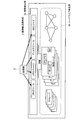
図1を参照して、本発明の実施の形態に係る障害通知部1が用いられる障害通知システム5を説明する。障害通知システム5は、複数のハードウエアが仮想化されたシステムである。障害通知システム5は、障害通知部1、論理構成提供部2、第1の処理部3a、第2の処理部3bおよび第3の処理部3cを備える。第1の処理部3a、第2の処理部3bおよび第3の処理部3cを特に区別しない場合、単に処理部3と記載する場合がある。
図1を参照して、本発明の実施の形態に係る障害通知部1が用いられる障害通知システム5を説明する。障害通知システム5は、複数のハードウエアが仮想化されたシステムである。障害通知システム5は、障害通知部1、論理構成提供部2、第1の処理部3a、第2の処理部3bおよび第3の処理部3cを備える。第1の処理部3a、第2の処理部3bおよび第3の処理部3cを特に区別しない場合、単に処理部3と記載する場合がある。
障害通知部1は、論理構成提供部2の各ハードウエアにアクセスして、論理構成提供部2の各ハードウエアの障害を処理部3に通知する。
論理構成提供部2は、複数のハードウエアを仮想化した論理構成を提供する。論理構成提供部2は、処理装置、記憶装置、通信制御装置、通信リンク等の複数のハードウエアから論理構成を提供する。
処理部3は、アプリケーションプログラムを実行する実行部であって、論理構成提供部2から提供された論理構成を利用する。
図2を参照して、論理構成提供部2と処理部3との関係を説明する。論理構成提供部2は、論理構成部2aとハードウエア構成部2bを備える。論理構成部2aは、論理構成提供部2が提供する論理構成で、CPUリソース、メモリリソース、ディスクリソースおよびネットワークリソース等である。ハードウエア構成部2bは、論理構成部2aの各リソースの実態となる物理的なハードウエアであって、ディスク、CPUメモリ、NIC等を備える物理ハード、ストレージ(記憶装置)、通信制御装置、ネットワークケーブル等である。
論理構成提供部2は、処理部3が指定したリソースに、ハードウエアを割り当てて、処理部3の処理に利用する。また論理構成提供部2は、処理部3が指定したリソースに割り当てるハードウエアを増減することで、処理部3の処理を変更することなく、処理部3の処理に必要なリソースを適切に割り当てることができる。また処理部3にはハードウエア構成が隠蔽されるので、ハードウエアが障害等により置換されても、処理部3はハードウエアの置換に関わらず円滑に処理をすることができる。
(障害通知装置)
図3を参照して、本発明の実施の形態に係る障害通知部(障害通知装置)1を説明する。障害通知部1は、論理構成提供部2の各ハードウエアに接続可能である。
図3を参照して、本発明の実施の形態に係る障害通知部(障害通知装置)1を説明する。障害通知部1は、論理構成提供部2の各ハードウエアに接続可能である。
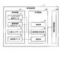
障害通知部1は、記憶装置10、処理装置20、通信制御装置30を備える。障害通知部1は、一般的な一つのコンピュータであっても良いし、複数のハードウエアにより形成される仮想的なコンピュータであっても良い。このようなコンピュータが障害通知プログラムを実行することにより、図3に示す機能が実現される。
記憶装置10は、ROM(Read Only Memory)、RAM(Random access memory)、ハードディスク等であって、処理装置20が処理を実行するための入力データ、出力データおよび中間データなどの各種データを記憶する。処理装置20は、CPU(Central Processing Unit)であって、記憶装置10に記憶されたデータを読み書きしたり、通信制御装置30とデータを入出力したりして、障害通知部1における処理を実行する。通信制御装置30は、障害通知部1が、他の装置等と通信可能に接続するためのインタフェースである。
記憶装置10は、障害通知プログラムを記憶するとともに、ハードウエア構成データ11、論理構成トポロジデータ12、冗長タイプデータ13、および処理部データ14を記憶する。
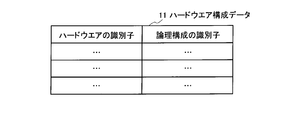
ハードウエア構成データ11は、図4に示すように、論理構成提供部2が備えるハードウエアの識別子と、ハードウエアに対応する論理構成の識別子を対応づける。論理構成提供部2の論理構成部2aの各論理構成と、ハードウエア構成部2bの各ハードウエアとの対応づけが変更されたり、論理構成またはハードウエア構成が増減されたりした際に、ハードウエア構成データ11は更新される。
論理構成トポロジデータ12は、図5(a)に示すように、論理構成提供部2の論理構成の接続状態を示す。図5(a)は、論理構成のうち、論理構成をグラフとして示しているが、異なる形態で示しても良い。
冗長タイプデータ13は、論理構成の識別子と、論理構成の冗長タイプを対応づける。冗長タイプは、冗長の有無と、冗長がある場合その冗長の種別である。
例えば、論理構成が装置間のリンクの場合、冗長タイプは、ACT/SBY構成、リンクアグリゲーション型などである。ACT/SBY構成は、障害が発生しても、系が切り替えられることを示し、障害発生前後で同様のリソースを提供できることを示す。リンクアグリゲーション型は、複数のハードウエアで一つのリソースを統合して提供することを示し、障害発生前後で、提供可能なリソースの量、質等に変化が生じることを示す。例えば、リンクアグリゲーション型として、複数のポートを束ねて一つのリンクを提供する方式がある。この方式において、一つのポートに障害が発生しても、リンクは通信可能であるが、そのリンクで提供可能な通信帯域が減少する。
図5(b)は、図5(a)に示す論理構成のトポロジに対応するハードウエア構成のトポロジの例である。図5(b)に示すハードウエア構成において、L2スイッチSWP1とL2スイッチSWP4との間に、L2スイッチSWP2およびL2スイッチSWP3が並列に設けられ、冗長に構成されている。従って、図5(a)に示す論理構成において、L2スイッチSWR1およびL2スイッチSWR2間のリンクLR1と、L2スイッチSWR2およびL2スイッチSWR3間のリンクLR2について、冗長タイプデータ13は、それぞれ、冗長ありと設定する。
図5(a)のリンクLR1は、図5(b)におけるL2スイッチSWP1およびL2スイッチSWP2間のリンクLP1と、L2スイッチSWP1およびL2スイッチSWP3間のリンクLP2の論理構成である。同様に、図5(a)のリンクLR2は、図5(b)におけるL2スイッチSWP2およびL2スイッチSWP4間のリンクLP3と、L2スイッチSWP3およびL2スイッチSWP4間のリンクLP4の論理構成である。図5(b)に示すハードウエア構成では、系を切り替えられることから、冗長タイプデータ13は、リンクLR1とリンクLR2のそれぞれついて、冗長タイプがACT/SBY構成と設定する。
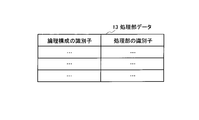
処理部データ14は、論理構成の識別子と、その論理構成を利用する処理部3の識別子を対応づける。処理部データ14は、処理部3の仕様の変更等に応じて更新される。
処理装置20は、検知部21、論理構成特定部22および通知部23を備える。
検知部21は、論理構成提供部2のハードウエア構成部2bの各ハードウエアについて、障害の有無を検知する。検知部21は、各ハードウエアに対して障害を問い合わせるコマンドを送信し、その返信内容から障害を検知しても良いし、ハードウエアからの通知によって、障害の有無を検知しても良い。また従来と同様に、ハードウエアに対してPINGコマンドを送信し、その返信の有無によって、ハードウエアの障害の有無を検知しても良い。
検知部21は、論理構成提供部2のハードウエア構成部2bの各ハードウエアについて、障害の有無を検知する。検知部21は、各ハードウエアに対して障害を問い合わせるコマンドを送信し、その返信内容から障害を検知しても良いし、ハードウエアからの通知によって、障害の有無を検知しても良い。また従来と同様に、ハードウエアに対してPINGコマンドを送信し、その返信の有無によって、ハードウエアの障害の有無を検知しても良い。
論理構成特定部22は、検知部21によってハードウエアの障害が検知されると、ハードウエア構成データから、障害が検知されたハードウエアに対応する論理構成を特定する。論理構成特定部22は、障害が検知されたハードウエアについて、処理部3が把握可能な論理構成を特定する。
論理構成特定部22はさらに、論理構成トポロジデータ12と冗長タイプデータ13を参照して、障害が検知されたハードウエアの影響を受ける論理構成とその影響内容を特定する。論理構成特定部22は、障害が検知されたハードウエアに対応する論理構成における冗長の有無によって処理を振り分ける。
障害が生じた論理構成が冗長に形成されていない場合、処理部3は、障害が生じた論理構成のみならず、その論理構成に接続する各論理構成も利用できない。論理構成特定部22は、処理部3に通知する論理構成として、障害が検知されたハードウエアに対応する論理構成のほか、その論理構成に接続する論理構成を、処理部3への通知対象として特定する。
障害が生じた論理構成が冗長に形成されている場合、その冗長の種別によって影響内容が異なるので、論理構成特定部22は、冗長の種別に応じて、影響内容を特定する。
例えば、冗長の種別がリンクアグリゲーション型の場合、処理は継続できるものの帯域が減少する影響が生じることから、論理構成特定部22は、処理部3に通知する内容として、障害が検知されたハードウエアに対応する論理構成のほか、帯域が減少する影響が生じるという影響内容を特定する。また冗長の種別がリンクアグリゲーション型の場合も、冗長がない場合と同様に論理構成提供部2における影響が生じるので、論理構成特定部22は、処理部3に通知する論理構成として、さらに、障害が検知されたハードウエアに対応する論理構成に接続する論理構成を、処理部3への通知対象として特定しても良い。
一方、図5に示すように冗長タイプがACT/SBY構成である場合、ハードウエア構成に障害が生じても系の切り替えで対応可能で、論理構成提供部2は、障害前と変わらず論理構成を提供することができる。従って論理構成特定部22は、検知部21が障害を検知したとしても、処理部3に通知すべき障害はないと判断しても良い。また他の例として論理構成特定部22は、ハードウエアに障害が発生したが系を切り替えて運用している旨を、処理部3に通知すべきと判断しても良い。
通知部23は、処理部3に、論理構成特定部22が特定した論理構成に障害が発生したことを通知する。通知部23はさらに、冗長の種別がリンクアグリゲーション型の場合など、処理は継続できるものの帯域が減少するなどの影響が生じる場合、論理構成特定部22が特定した影響内容を通知する。これらの通知により処理部3は、ハードウエアの障害を回避して、処理を変更するなどの対応を取ることができる。
また通知部23は、論理構成特定部22によって特定された論理構成を利用する処理部3に、その論理構成に障害が発生したことを通知しても良い。これにより通知部23は、障害に関連する処理部3に限定して障害の発生を通知するので、障害通知システム5における処理負荷を軽減することができる。
図8を参照して、障害通知システム5における障害通知方法を説明する。
通常運用時、ステップS1ないしステップS4の処理が継続的に行われる。ステップS1において論理構成提供部2は、処理部3に論理構成を提示し、ステップS2において処理部3は、論理構成提供部2が提示した論理構成を指定して、論理構成提供部2に処理を依頼する。論理構成提供部2は、処理部3によって指定された論理構成に対応するハードウエアを用いて、処理部3からの依頼に応じて処理を行い、その処理結果を処理部3に返す。またステップS3において障害通知部1は、論理構成提供部2の各ハードウエアについて、障害を問い合わせ、ステップS4において各ハードウエアの障害状況を取得する。
なおステップS1ないしステップS4の処理の順序は、図8に示すものに問わない。例えば、ステップS1およびステップS2の処理と、ステップS3およびステップS4の処理とが同時に行われても良い。また図8に示す例において、障害通知部1が論理構成提供部2に障害を問い合わせる場合を説明しているが、論理構成提供部2が、ハードウエアの障害を、障害通知部1に自発的に通知しても良い。
ステップS5において、ステップS4で取得した障害状況が障害を示すと判定する場合、障害通知部1はステップS6に進む。障害通知部1は、ステップS6において、障害が発生したハードウエアに対応する論理構成を特定し、ステップS7において、障害の影響を受ける論理構成とその影響内容を特定する。
ステップS8において障害通知部1は、ステップS6およびステップS7で特定した論理構成を利用する処理部3を特定する。ステップS9において障害通知部1は、ステップS9で特定した処理部3に対して、ステップS6およびステップS7で特定した論理構成とその影響内容を通知する。
このような本発明の実施の形態に係る障害通知部1は、論理構成提供部2の個々のハードウエアに障害を直接問い合わせて、各ハードウエアの障害状況を取得し、処理部3に通知する。また障害通知部1は、論理構成提供部2のハードウエアに生じた障害を、ハードウエアに対応する論理構成に置き換えて処理部3に通知する。これにより、複数のハードウエアを仮想化した論理構成を利用する処理部3は、論理構成の障害を適切に把握することができる。
従来、処理部3がPINGコマンドを送信して、そのコマンドを受信したハードウエアの生死を確認できたとしても、処理部3はハードウエアの構成を把握していないので、各ハードウエアに対して網羅的に生死を確認することはできない。これに対し本発明の実施の形態に係る障害通知部1は、論理構成提供部2の個々のハードウエアに障害を直接問い合わせて障害状況を取得できるので、各ハードウエアについてしょうがい状況を把握することができる。
また従来、PINGコマンドを送信してタイムアウトするか否かでハードウエアの生死を確認したが、タイムアウトまで待機しなければならない、間欠障害の事象が発生するまで待機しなければならないなど、障害が発生してからその検知まで時間を要する場合があった。これに対し本発明の実施の形態に係る障害通知システム5において、障害通知部1は、論理構成提供部2の個々のハードウエアに障害を直接問い合わせて取得した障害内容を処理部3に通知することができるので、処理部3は、論理構成提供部2の障害を即座に把握することができる。また障害通知部1は、PINGコマンドに依らず、ハードウエアから障害状況を取得することができるので、機能が一部停止するなどのフェイルソフト的な障害も把握することができる。
また障害通知部1は、論理構成トポロジデータ12および冗長タイプデータ13を参照して、ハードウエアに生じた障害の影響を受ける論理構成と、その影響内容を特定し、処理部3に通知する。これにより処理部3は、論理構成提供部2における障害を考慮して、適切に対応することができる。
(その他の実施の形態)
上記のように、本発明の実施の形態によって記載したが、この開示の一部をなす論述および図面はこの発明を限定するものであると理解すべきではない。この開示から当業者には様々な代替実施の形態、実施例および運用技術が明らかとなる。
上記のように、本発明の実施の形態によって記載したが、この開示の一部をなす論述および図面はこの発明を限定するものであると理解すべきではない。この開示から当業者には様々な代替実施の形態、実施例および運用技術が明らかとなる。
例えば、本発明の実施の形態に記載した障害通知部は、一般的な一つのコンピュータに実装されても良いし、複数のハードウエアにより仮想的に形成されるコンピュータに実装されても良い。
本発明はここでは記載していない様々な実施の形態等を含むことは勿論である。従って、本発明の技術的範囲は上記の説明から妥当な請求の範囲に係る発明特定事項によってのみ定められるものである。
1 障害通知部
2 論理構成提供部
2a 論理構成部
3 処理部
5 障害通知システム
10 記憶装置
11 ハードウエア構成データ
12 論理構成トポロジデータ
13 冗長タイプデータ
14 処理部データ
20 処理装置
21 検知部
22 論理構成特定部
23 通知部
2 論理構成提供部
2a 論理構成部
3 処理部
5 障害通知システム
10 記憶装置
11 ハードウエア構成データ
12 論理構成トポロジデータ
13 冗長タイプデータ
14 処理部データ
20 処理装置
21 検知部
22 論理構成特定部
23 通知部
Claims (6)
- 複数のハードウエアを仮想化した論理構成を提供する論理構成提供部と、前記論理構成提供部から提供された論理構成を利用する処理部と、前記論理構成提供部の障害を前記処理部に通知する障害通知部と、を備える障害通知システムであって、
前記障害通知部は、
前記ハードウエアの識別子と、前記ハードウエアに対応する論理構成の識別子を対応づけるハードウエア構成データを記憶する記憶装置と、
前記ハードウエアの障害が検知されると、前記ハードウエア構成データから、障害が検知されたハードウエアに対応する論理構成を特定する論理構成特定部と、
前記処理部に、前記論理構成特定部が特定した前記論理構成に障害が発生したことを通知する通知部
を備えることを特徴とする障害通知システム。 - 前記記憶装置は、さらに、前記論理構成の接続状態を示す論理構成トポロジデータと、前記論理構成の識別子と、前記論理構成の冗長タイプを対応づける冗長タイプデータを記憶し、
前記論理構成特定部はさらに、前記論理構成トポロジデータと前記冗長タイプデータを参照して、前記障害が検知されたハードウエアの影響を受ける論理構成とその影響内容を特定し、
前記通知部は、さらに、特定された影響内容を通知する
ことを特徴とする請求項1に記載の障害通知システム。 - 前記記憶装置は、さらに、前記論理構成の識別子と、前記論理構成を利用する処理部の識別子を対応づける処理部データを記憶し、
前記通知部は、前記論理構成特定部によって特定された論理構成を利用する処理部に、前記論理構成に障害が発生したことを通知する
ことを特徴とする請求項1または2に記載の障害通知システム。 - 複数のハードウエアを仮想化した論理構成を提供する論理構成提供部と、前記論理構成提供部から提供された論理構成を利用する処理部と、前記論理構成提供部の障害を前記処理部に通知する障害通知部と、を備える障害通知システムに用いられる障害通知方法であって、
コンピュータが、前記ハードウエアの識別子と、前記ハードウエアに対応する論理構成の識別子を対応づけるハードウエア構成データを、記憶装置に記憶するステップと、
前記コンピュータが、前記ハードウエアの障害が検知されると、前記ハードウエア構成データから、障害が検知されたハードウエアに対応する論理構成を特定するステップと、
前記コンピュータが、前記処理部に、前記特定するステップで特定した前記論理構成に障害が発生したことを通知するステップ
を備えることを特徴とする障害通知方法。 - 複数のハードウエアを仮想化した論理構成を提供する論理構成提供部と、前記論理構成提供部から提供された論理構成を利用する処理部と、前記論理構成提供部の障害を前記処理部に通知する障害通知部と、を備える障害通知システムにおいて、前記障害通知部として機能する障害通知装置であって、
前記ハードウエアの識別子と、前記ハードウエアに対応する論理構成の識別子を対応づけるハードウエア構成データを記憶する記憶装置と、
前記ハードウエアの障害が検知されると、前記ハードウエア構成データから、障害が検知されたハードウエアに対応する論理構成を特定する論理構成特定部と、
前記処理部に、前記論理構成特定部が特定した前記論理構成に障害が発生したことを通知する通知部
を備えることを特徴とする障害通知装置。 - コンピュータを、請求項5に記載の障害通知装置として機能させるための障害通知プログラム。
Priority Applications (1)
| Application Number | Priority Date | Filing Date | Title |
|---|---|---|---|
| US17/426,429 US11652683B2 (en) | 2019-02-05 | 2020-01-22 | Failure notification system, failure notification method, failure notification device, and failure notification program |
Applications Claiming Priority (2)
| Application Number | Priority Date | Filing Date | Title |
|---|---|---|---|
| JP2019018633A JP7193722B2 (ja) | 2019-02-05 | 2019-02-05 | 障害通知システム、障害通知方法、障害通知装置および障害通知プログラム |
| JP2019-018633 | 2019-02-05 |
Publications (1)
| Publication Number | Publication Date |
|---|---|
| WO2020162165A1 true WO2020162165A1 (ja) | 2020-08-13 |
Family
ID=71947409
Family Applications (1)
| Application Number | Title | Priority Date | Filing Date |
|---|---|---|---|
| PCT/JP2020/002013 Ceased WO2020162165A1 (ja) | 2019-02-05 | 2020-01-22 | 障害通知システム、障害通知方法、障害通知装置および障害通知プログラム |
Country Status (3)
| Country | Link |
|---|---|
| US (1) | US11652683B2 (ja) |
| JP (1) | JP7193722B2 (ja) |
| WO (1) | WO2020162165A1 (ja) |
Citations (2)
| Publication number | Priority date | Publication date | Assignee | Title |
|---|---|---|---|---|
| JP2017135653A (ja) * | 2016-01-29 | 2017-08-03 | 富士通株式会社 | 試験装置、ネットワークシステム、及び試験方法 |
| WO2017170310A1 (ja) * | 2016-03-31 | 2017-10-05 | 日本電気株式会社 | ネットワークシステムにおける管理方法および管理装置 |
Family Cites Families (3)
| Publication number | Priority date | Publication date | Assignee | Title |
|---|---|---|---|---|
| JP5636505B2 (ja) * | 2011-05-31 | 2014-12-03 | 株式会社日立製作所 | 計算機システム及びそのイベント通知方法 |
| CN106557399B (zh) * | 2015-09-25 | 2019-09-06 | 伊姆西公司 | 用于呈现存储集群的状态的方法和装置 |
| CN108139925B (zh) * | 2016-05-31 | 2022-06-03 | 安华高科技股份有限公司 | 虚拟机的高可用性 |
-
2019
- 2019-02-05 JP JP2019018633A patent/JP7193722B2/ja active Active
-
2020
- 2020-01-22 US US17/426,429 patent/US11652683B2/en active Active
- 2020-01-22 WO PCT/JP2020/002013 patent/WO2020162165A1/ja not_active Ceased
Patent Citations (2)
| Publication number | Priority date | Publication date | Assignee | Title |
|---|---|---|---|---|
| JP2017135653A (ja) * | 2016-01-29 | 2017-08-03 | 富士通株式会社 | 試験装置、ネットワークシステム、及び試験方法 |
| WO2017170310A1 (ja) * | 2016-03-31 | 2017-10-05 | 日本電気株式会社 | ネットワークシステムにおける管理方法および管理装置 |
Also Published As
| Publication number | Publication date |
|---|---|
| US20220103416A1 (en) | 2022-03-31 |
| US11652683B2 (en) | 2023-05-16 |
| JP2020127138A (ja) | 2020-08-20 |
| JP7193722B2 (ja) | 2022-12-21 |
Similar Documents
| Publication | Publication Date | Title |
|---|---|---|
| JP5074274B2 (ja) | 計算機システム及び通信経路の監視方法 | |
| US20200073656A1 (en) | Method and Apparatus for Drift Management in Clustered Environments | |
| CN103491134B (zh) | 一种监控容器的方法、装置与代理服务系统 | |
| CN112199240A (zh) | 一种节点故障时进行节点切换的方法及相关设备 | |
| EP2740255A1 (en) | Hardware failure mitigation | |
| US11360832B2 (en) | Operation method of robot operating system and a robot control method | |
| CN108170507B (zh) | 虚拟应用管理方法/系统、计算机可读存储介质及服务端 | |
| CN112217658B (zh) | 一种堆叠分裂处理方法及装置 | |
| JP4529767B2 (ja) | クラスタ構成コンピュータシステム及びその系リセット方法 | |
| WO2023275983A1 (ja) | 仮想化システム障害分離装置及び仮想化システム障害分離方法 | |
| JP5712714B2 (ja) | クラスタシステム、仮想マシンサーバ、仮想マシンのフェイルオーバ方法、仮想マシンのフェイルオーバプログラム | |
| CN116032728A (zh) | 用于微服务环境的智能访问方法、系统 | |
| US9104632B2 (en) | Enhanced failover mechanism in a network virtualized environment | |
| JP7193722B2 (ja) | 障害通知システム、障害通知方法、障害通知装置および障害通知プログラム | |
| CN106095606B (zh) | 一种服务器的软件故障处理方法和装置 | |
| WO2021047619A1 (zh) | 虚拟网卡链路状态设置方法、装置及存储介质 | |
| US11881982B2 (en) | Transaction-based messaging and logging infrastructure for networking systems and computing devices | |
| CN117793034A (zh) | 网卡添加方法、装置、计算设备及机器可读存储介质 | |
| WO2023275985A1 (ja) | 仮想化システム障害分離装置及び仮想化システム障害分離方法 | |
| CN113765748A (zh) | 计算节点故障处理方法和计算机可读存储介质 | |
| CN120743638B (zh) | 一种rdma双网卡主备切换方法及设备 | |
| JP2016158092A (ja) | 表示システム、表示方法、表示プログラムおよび仮想システム | |
| CN119342090A (zh) | 一种微服务管理方法及相关设备 | |
| CN103873429B (zh) | 确定节点状态的方法和节点 | |
| Wang et al. | An approach for fast fault detection in virtual network |
Legal Events
| Date | Code | Title | Description |
|---|---|---|---|
| 121 | Ep: the epo has been informed by wipo that ep was designated in this application |
Ref document number: 20752438 Country of ref document: EP Kind code of ref document: A1 |
|
| NENP | Non-entry into the national phase |
Ref country code: DE |
|
| 122 | Ep: pct application non-entry in european phase |
Ref document number: 20752438 Country of ref document: EP Kind code of ref document: A1 |