WO2020162059A1 - 酔い状態判定システム、生体情報取得装置、周囲環境情報取得装置、酔い状態判定装置、及び酔い状態判定方法 - Google Patents
酔い状態判定システム、生体情報取得装置、周囲環境情報取得装置、酔い状態判定装置、及び酔い状態判定方法 Download PDFInfo
- Publication number
- WO2020162059A1 WO2020162059A1 PCT/JP2019/049889 JP2019049889W WO2020162059A1 WO 2020162059 A1 WO2020162059 A1 WO 2020162059A1 JP 2019049889 W JP2019049889 W JP 2019049889W WO 2020162059 A1 WO2020162059 A1 WO 2020162059A1
- Authority
- WO
- WIPO (PCT)
- Prior art keywords
- sickness
- target
- sickness state
- index
- information
- Prior art date
- Legal status (The legal status is an assumption and is not a legal conclusion. Google has not performed a legal analysis and makes no representation as to the accuracy of the status listed.)
- Ceased
Links
Images












Classifications
-
- G—PHYSICS
- G06—COMPUTING OR CALCULATING; COUNTING
- G06F—ELECTRIC DIGITAL DATA PROCESSING
- G06F3/00—Input arrangements for transferring data to be processed into a form capable of being handled by the computer; Output arrangements for transferring data from processing unit to output unit, e.g. interface arrangements
- G06F3/01—Input arrangements or combined input and output arrangements for interaction between user and computer
- G06F3/011—Arrangements for interaction with the human body, e.g. for user immersion in virtual reality
- G06F3/012—Head tracking input arrangements
-
- A—HUMAN NECESSITIES
- A61—MEDICAL OR VETERINARY SCIENCE; HYGIENE
- A61B—DIAGNOSIS; SURGERY; IDENTIFICATION
- A61B5/00—Measuring for diagnostic purposes; Identification of persons
- A61B5/16—Devices for psychotechnics; Testing reaction times ; Devices for evaluating the psychological state
- A61B5/165—Evaluating the state of mind, e.g. depression, anxiety
-
- A—HUMAN NECESSITIES
- A61—MEDICAL OR VETERINARY SCIENCE; HYGIENE
- A61B—DIAGNOSIS; SURGERY; IDENTIFICATION
- A61B10/00—Instruments for taking body samples for diagnostic purposes; Other methods or instruments for diagnosis, e.g. for vaccination diagnosis, sex determination or ovulation-period determination; Throat striking implements
-
- A—HUMAN NECESSITIES
- A61—MEDICAL OR VETERINARY SCIENCE; HYGIENE
- A61B—DIAGNOSIS; SURGERY; IDENTIFICATION
- A61B5/00—Measuring for diagnostic purposes; Identification of persons
- A61B5/103—Measuring devices for testing the shape, pattern, colour, size or movement of the body or parts thereof, for diagnostic purposes
- A61B5/11—Measuring movement of the entire body or parts thereof, e.g. head or hand tremor or mobility of a limb
- A61B5/1113—Local tracking of patients, e.g. in a hospital or private home
- A61B5/1114—Tracking parts of the body
-
- A—HUMAN NECESSITIES
- A61—MEDICAL OR VETERINARY SCIENCE; HYGIENE
- A61B—DIAGNOSIS; SURGERY; IDENTIFICATION
- A61B5/00—Measuring for diagnostic purposes; Identification of persons
- A61B5/103—Measuring devices for testing the shape, pattern, colour, size or movement of the body or parts thereof, for diagnostic purposes
- A61B5/11—Measuring movement of the entire body or parts thereof, e.g. head or hand tremor or mobility of a limb
- A61B5/1121—Determining geometric values, e.g. centre of rotation or angular range of movement
-
- A—HUMAN NECESSITIES
- A61—MEDICAL OR VETERINARY SCIENCE; HYGIENE
- A61B—DIAGNOSIS; SURGERY; IDENTIFICATION
- A61B5/00—Measuring for diagnostic purposes; Identification of persons
- A61B5/40—Detecting, measuring or recording for evaluating the nervous system
- A61B5/4076—Diagnosing or monitoring particular conditions of the nervous system
-
- A—HUMAN NECESSITIES
- A61—MEDICAL OR VETERINARY SCIENCE; HYGIENE
- A61B—DIAGNOSIS; SURGERY; IDENTIFICATION
- A61B5/00—Measuring for diagnostic purposes; Identification of persons
- A61B5/42—Detecting, measuring or recording for evaluating the gastrointestinal, the endocrine or the exocrine systems
- A61B5/4261—Evaluating exocrine secretion production
- A61B5/4277—Evaluating exocrine secretion production saliva secretion
-
- A—HUMAN NECESSITIES
- A61—MEDICAL OR VETERINARY SCIENCE; HYGIENE
- A61B—DIAGNOSIS; SURGERY; IDENTIFICATION
- A61B5/00—Measuring for diagnostic purposes; Identification of persons
- A61B5/68—Arrangements of detecting, measuring or recording means, e.g. sensors, in relation to patient
- A61B5/6801—Arrangements of detecting, measuring or recording means, e.g. sensors, in relation to patient specially adapted to be attached to or worn on the body surface
- A61B5/6802—Sensor mounted on worn items
- A61B5/6803—Head-worn items, e.g. helmets, masks, headphones or goggles
-
- G—PHYSICS
- G01—MEASURING; TESTING
- G01N—INVESTIGATING OR ANALYSING MATERIALS BY DETERMINING THEIR CHEMICAL OR PHYSICAL PROPERTIES
- G01N33/00—Investigating or analysing materials by specific methods not covered by groups G01N1/00 - G01N31/00
- G01N33/48—Biological material, e.g. blood, urine; Haemocytometers
- G01N33/50—Chemical analysis of biological material, e.g. blood, urine; Testing involving biospecific ligand binding methods; Immunological testing
- G01N33/68—Chemical analysis of biological material, e.g. blood, urine; Testing involving biospecific ligand binding methods; Immunological testing involving proteins, peptides or amino acids
-
- G—PHYSICS
- G06—COMPUTING OR CALCULATING; COUNTING
- G06F—ELECTRIC DIGITAL DATA PROCESSING
- G06F3/00—Input arrangements for transferring data to be processed into a form capable of being handled by the computer; Output arrangements for transferring data from processing unit to output unit, e.g. interface arrangements
- G06F3/01—Input arrangements or combined input and output arrangements for interaction between user and computer
- G06F3/011—Arrangements for interaction with the human body, e.g. for user immersion in virtual reality
- G06F3/014—Hand-worn input/output arrangements, e.g. data gloves
-
- G—PHYSICS
- G06—COMPUTING OR CALCULATING; COUNTING
- G06F—ELECTRIC DIGITAL DATA PROCESSING
- G06F3/00—Input arrangements for transferring data to be processed into a form capable of being handled by the computer; Output arrangements for transferring data from processing unit to output unit, e.g. interface arrangements
- G06F3/01—Input arrangements or combined input and output arrangements for interaction between user and computer
- G06F3/016—Input arrangements with force or tactile feedback as computer generated output to the user
-
- G—PHYSICS
- G06—COMPUTING OR CALCULATING; COUNTING
- G06F—ELECTRIC DIGITAL DATA PROCESSING
- G06F3/00—Input arrangements for transferring data to be processed into a form capable of being handled by the computer; Output arrangements for transferring data from processing unit to output unit, e.g. interface arrangements
- G06F3/01—Input arrangements or combined input and output arrangements for interaction between user and computer
- G06F3/03—Arrangements for converting the position or the displacement of a member into a coded form
- G06F3/033—Pointing devices displaced or positioned by the user, e.g. mice, trackballs, pens or joysticks; Accessories therefor
- G06F3/0346—Pointing devices displaced or positioned by the user, e.g. mice, trackballs, pens or joysticks; Accessories therefor with detection of the device orientation or free movement in a three-dimensional [3D] space, e.g. 3D mice, 6-DOF [six degrees of freedom] pointers using gyroscopes, accelerometers or tilt-sensors
-
- G—PHYSICS
- G06—COMPUTING OR CALCULATING; COUNTING
- G06T—IMAGE DATA PROCESSING OR GENERATION, IN GENERAL
- G06T7/00—Image analysis
- G06T7/20—Analysis of motion
-
- A—HUMAN NECESSITIES
- A61—MEDICAL OR VETERINARY SCIENCE; HYGIENE
- A61B—DIAGNOSIS; SURGERY; IDENTIFICATION
- A61B2560/00—Constructional details of operational features of apparatus; Accessories for medical measuring apparatus
- A61B2560/02—Operational features
- A61B2560/0242—Operational features adapted to measure environmental factors, e.g. temperature, pollution
-
- A—HUMAN NECESSITIES
- A61—MEDICAL OR VETERINARY SCIENCE; HYGIENE
- A61B—DIAGNOSIS; SURGERY; IDENTIFICATION
- A61B2562/00—Details of sensors; Constructional details of sensor housings or probes; Accessories for sensors
- A61B2562/02—Details of sensors specially adapted for in-vivo measurements
- A61B2562/0219—Inertial sensors, e.g. accelerometers, gyroscopes, tilt switches
-
- A—HUMAN NECESSITIES
- A61—MEDICAL OR VETERINARY SCIENCE; HYGIENE
- A61B—DIAGNOSIS; SURGERY; IDENTIFICATION
- A61B5/00—Measuring for diagnostic purposes; Identification of persons
- A61B5/02—Detecting, measuring or recording for evaluating the cardiovascular system, e.g. pulse, heart rate, blood pressure or blood flow
- A61B5/0205—Simultaneously evaluating both cardiovascular conditions and different types of body conditions, e.g. heart and respiratory condition
-
- A—HUMAN NECESSITIES
- A61—MEDICAL OR VETERINARY SCIENCE; HYGIENE
- A61B—DIAGNOSIS; SURGERY; IDENTIFICATION
- A61B5/00—Measuring for diagnostic purposes; Identification of persons
- A61B5/103—Measuring devices for testing the shape, pattern, colour, size or movement of the body or parts thereof, for diagnostic purposes
- A61B5/11—Measuring movement of the entire body or parts thereof, e.g. head or hand tremor or mobility of a limb
- A61B5/1126—Measuring movement of the entire body or parts thereof, e.g. head or hand tremor or mobility of a limb using a particular sensing technique
- A61B5/1128—Measuring movement of the entire body or parts thereof, e.g. head or hand tremor or mobility of a limb using a particular sensing technique using image analysis
-
- A—HUMAN NECESSITIES
- A61—MEDICAL OR VETERINARY SCIENCE; HYGIENE
- A61B—DIAGNOSIS; SURGERY; IDENTIFICATION
- A61B5/00—Measuring for diagnostic purposes; Identification of persons
- A61B5/145—Measuring characteristics of blood in vivo, e.g. gas concentration or pH-value ; Measuring characteristics of body fluids or tissues, e.g. interstitial fluid or cerebral tissue
- A61B5/1468—Measuring characteristics of blood in vivo, e.g. gas concentration or pH-value ; Measuring characteristics of body fluids or tissues, e.g. interstitial fluid or cerebral tissue using chemical or electrochemical methods, e.g. by polarographic means
- A61B5/1486—Measuring characteristics of blood in vivo, e.g. gas concentration or pH-value ; Measuring characteristics of body fluids or tissues, e.g. interstitial fluid or cerebral tissue using chemical or electrochemical methods, e.g. by polarographic means using enzyme electrodes, e.g. with immobilised oxidase
-
- A—HUMAN NECESSITIES
- A61—MEDICAL OR VETERINARY SCIENCE; HYGIENE
- A61B—DIAGNOSIS; SURGERY; IDENTIFICATION
- A61B5/00—Measuring for diagnostic purposes; Identification of persons
- A61B5/40—Detecting, measuring or recording for evaluating the nervous system
- A61B5/4005—Detecting, measuring or recording for evaluating the nervous system for evaluating the sensory system
- A61B5/4011—Evaluating olfaction, i.e. sense of smell
-
- A—HUMAN NECESSITIES
- A61—MEDICAL OR VETERINARY SCIENCE; HYGIENE
- A61B—DIAGNOSIS; SURGERY; IDENTIFICATION
- A61B5/00—Measuring for diagnostic purposes; Identification of persons
- A61B5/68—Arrangements of detecting, measuring or recording means, e.g. sensors, in relation to patient
- A61B5/6801—Arrangements of detecting, measuring or recording means, e.g. sensors, in relation to patient specially adapted to be attached to or worn on the body surface
- A61B5/6813—Specially adapted to be attached to a specific body part
- A61B5/6814—Head
- A61B5/682—Mouth, e.g., oral cavity; tongue; Lips; Teeth
-
- A—HUMAN NECESSITIES
- A61—MEDICAL OR VETERINARY SCIENCE; HYGIENE
- A61B—DIAGNOSIS; SURGERY; IDENTIFICATION
- A61B5/00—Measuring for diagnostic purposes; Identification of persons
- A61B5/68—Arrangements of detecting, measuring or recording means, e.g. sensors, in relation to patient
- A61B5/6801—Arrangements of detecting, measuring or recording means, e.g. sensors, in relation to patient specially adapted to be attached to or worn on the body surface
- A61B5/6813—Specially adapted to be attached to a specific body part
- A61B5/6814—Head
- A61B5/6821—Eye
Definitions
- the present technology relates to a sickness determination system, a biological information acquisition device, a surrounding environment information acquisition device, and a sickness determination method. More specifically, the present technology, a sickness state determination system that determines a sickness state of a target based on two sickness state indexes, a biometric information acquisition device, a surrounding environment information acquisition device, and a sickness state determination device that configure the system, The present invention also relates to a sickness state determination method for determining the sickness state of a target based on two sickness state indexes.
- drugs containing antihistamine as the main ingredient are generally on the market.
- the functionality of the drug has been improved such that the duration of the effect of one dose is prolonged or the drug can be taken without water.
- Patent Document 1 discloses a vehicle occupant posture control device intended to suppress the occurrence of vehicle sickness of an occupant.
- the device a plurality of detection unit for detecting each of the vehicle surrounding information and the state of the vehicle, a change unit for changing the support state of the support unit that supports the body of the occupant, based on the detection result of the detection unit, A travel plan is generated, operation of the vehicle is controlled in accordance with the generated travel plan, and accelerations in the vehicle front-rear direction and the vehicle width direction that occur in the vehicle after a predetermined time has elapsed from the current time based on the generated travel plan are generated.
- a driving control unit that predicts and starts changing the supporting state according to the predicted acceleration, and controls the changing unit so that the supporting state matches the predicted acceleration by the elapse of a predetermined time. Equipped with.
- Patent Document 2 has a low-frequency generation function for transmitting low frequencies to the median nerve of the wrist so as to effectively block nausea and vomiting due to motion sickness, morning sickness, drugs, or the like.
- a wearable device is disclosed.
- the device includes a main body, which is provided on a wrist and includes a low frequency generation unit that generates a low frequency.
- measures against VR motion sickness for example, measures by video effects have been considered, such as visualizing an acceleration effect in a game video, intentionally narrowing a field of view in the video, and clearly showing a user's gaze direction in the video. ..
- the effect of suppressing sickness may differ depending on the user's constitution or the user's daily physical condition, or side effects such as drowsiness and malaise may occur.
- the drug must be taken 30 minutes to 1 hour before the effect is expected, and is not immediate. In addition, many people do not want their children to take medicine too much.
- Patent Documents 1 and 2 above do not detect the occurrence of a sickness state or a sign of the sickness state according to each user, and cannot effectively suppress the sickness.
- the video effects for VR sickness countermeasures are first created with the feeling of the game developer, and the created video effects are finally adjusted based on the play questionnaire of a limited number of test users. Therefore, the effect of suppressing motion sickness may differ for each user. Further, in view of the further spread of VR in the future, it is expected that more diverse users will play the VR game, and therefore it is easily expected that the effect cannot be further expected.
- the present inventors have found that the above problems can be solved by a sickness state determination system having a specific configuration.
- the present technology is based on a first index acquisition unit that acquires biometric information of a target as a first sickness state index, and motion information related to the motion of the target and/or ambient environment information perceived by the target.
- a second index acquisition unit that acquires a sickness state index, and a sickness state that determines whether or not the subject is in a sickness state based on the first sickness state index and the second sickness state index
- a sickness state determination system including a determination unit.
- the sickness state determination system may further include a sickness state control unit that controls a sickness state of the target based on a determination result of the sickness state determination unit.
- the sickness state control unit may determine a treatment content for controlling the sickness state based on the information acquired from the database.
- the sickness determination system may determine the sickness of the target in real time.
- the sickness state determination unit determines that the target is in or is in a sickness state.
- the biological information may include information about the enzyme derived from the subject.
- the enzyme may be an amylase.
- the motion information is motion information related to a motion of the body of the target
- the ambient environment information is video information related to an image visually perceived by the target
- the second index acquisition unit may acquire the second motion sickness index based on the motion information and the video information.
- the movement information is first acceleration information based on a movement of the body of the target, and the surrounding environment information is second acceleration information based on an image visually perceived by the target, Moreover, the second index acquisition unit may acquire a second motion sickness index based on the first acceleration information and the second acceleration information. In the embodiment, the second index acquisition unit may acquire a difference between the first acceleration information and the second acceleration information as the second motion sickness index. In the embodiment, a sickness state control unit that applies a current to the head of the target based on the determination result of the sickness state determination unit may be further included.
- the surrounding environment information is odor information regarding an odor that the object perceives by the sense of smell
- the second index acquisition unit based on the odor information, a second sickness state The index can be obtained.
- the second index acquisition unit can acquire the intensity of a predetermined type of odor as the second sickness state index.
- a sickness state control unit that presents an odor to the target or removes an odor around the target based on the determination result of the sickness state determination unit may be further included.
- the sickness state determination system according to the present technology may further include an output unit that outputs a determination result of the sickness state determination unit.
- the present technology includes a biometric information acquisition unit that acquires biometric information of a target, and in order to determine the motion sickness of the target, the motion information related to the motion of the target and/or the target is perceived.
- a biometric information acquisition device used in combination with an index acquisition device that acquires a motion sickness index based on surrounding environment information.
- the present technology includes a surrounding environment information acquisition unit that acquires surrounding environment information perceived by the target, and, in order to determine the sickness state of the target, acquires the biological information of the target as a sickness state index. Also provided is a surrounding environment information acquisition device used in combination with the biological information acquisition device.
- the present technology is based on a first index acquisition unit that acquires biometric information of a target as a first sickness state index, and motion information related to the motion of the target and/or ambient environment information perceived by the target
- a second index acquisition unit that acquires a sickness state index, and a sickness state that determines whether or not the subject is in a sickness state based on the first sickness state index and the second sickness state index
- a sickness state determination device including a determination unit is also provided.
- the present technology is based on a first index acquisition step of acquiring biometric information of a target as a first sickness state index, and motion information related to the motion of the target and/or surrounding environment information perceived by the target, A second index acquisition step of acquiring a sickness state index, and a sickness state for determining whether or not the target is in a sickness state based on the first sickness state index and the second sickness state index
- a sickness state determination method including a determination step is also provided.
- First embodiment silkness state determination system
- First example of the first embodiment (example of determination based on amylase activity and acceleration) (3)
- Second example of first embodiment (application example to VR device) (4)
- Third Example of First Embodiment (Application Example to VR Game Development) (5)
- Fourth example of the first embodiment (application example to an attraction of an amusement park) (6)
- Fifth example of the first embodiment (application example to a training simulator) (7)
- Sixth example of the first embodiment (example of determination based on amylase activity and odor) 2.
- Second embodiment biological information acquisition device
- Third embodiment ambient environment information acquisition device
- Fourth embodiment (sickness state determination device) 5.
- Fifth embodiment (sickness determination method)
- the second motion sickness acquired based on the first motion sickness index that is the biometric information of the target and the motion information regarding the motion of the target and/or the surrounding environment information perceived by the target. Based on the state index, it is determined whether or not the subject is in a sickness state. By determining the sickness state of the target based on the two indexes, the sickness state of the target can be appropriately determined. Furthermore, since the motion sickness determination system of the present technology can appropriately determine the motion sickness of the target, it is also possible to appropriately prevent or suppress the motion sickness.
- FIG. 1 is a diagram for explaining the principle of sickness.
- the inner ear has vestibular organs.
- the vestibular organ is an acceleration detecting organ for the human body and can detect linear motion and rotational acceleration.
- the vestibular organ includes a semicircular canal and an otolith.
- the semicircular canal senses movements in all three-dimensional directions (rotational acceleration), and the otolithic senses movements in a straight direction (linear acceleration) and gravity.
- a person visually acquires visual information such as an external landscape.
- the information perceived by the vestibular organ and the visual information perceived by the eyes may not match, for example, when a user is moving in a vehicle or watching an image with a VR device.
- a schematic diagram for explaining the inconsistency between the vestibular information and the visual information is shown in FIG.
- the mismatch may occur, for example, when the acceleration sensed by the vestibular organ is higher than the acceleration based on the visual information perceived by the eyes.
- the reverse mismatch can also occur.
- acceleration is detected by the vestibular organ, but acceleration is not visually recognized, and further, acceleration is visually recognized but acceleration is not detected by the vestibular organ.
- Inconsistency between vestibular information and visual information can cause a sickness.
- the inconsistency of these pieces of information is notified to the amygdala of the limbic system, and it is judged whether these pieces of information are pleasant or unpleasant. If the information is determined to be unpleasant information, a sickness may occur.
- the discomfort information stimulates the sympathetic nervous system via the hypothalamus, and the stress hormone is secreted into the body.
- the stress hormone may cause a reaction of the human body that indicates a state of sickness.
- the reaction of the human body for example, the face becomes pale, sweating cold, and spiting out are mentioned. Further worsening sickness can result in vomiting or large up and down changes in blood pressure.
- various biological reactions occur when the person is in a sickness state or is in a sick state.
- environmental factors around humans such as odor, temperature, and humidity can also cause a sickness state.
- odor, temperature, and humidity can also cause motion sickness.
- a scent in a car for example, can cause motion sickness.
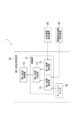
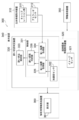
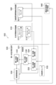
- FIG. 3 shows a schematic block diagram of an example of the sickness state determination system according to the first embodiment of the present technology.
- the sickness state determination system 1 shown in FIG. 3 includes a sickness state determination device 10, a biological information acquisition device 20, and a surrounding environment information acquisition device 30. Each of these devices will be described below.
- the motion sickness determination device 10 includes a control unit 11.
- the control unit 11 includes a first index acquisition unit 12, a second index acquisition unit 13, and a sickness state determination unit 14.
- the motion sickness determination device 10 may or may not further include the motion sickness control unit 15.
- the motion sickness determination device 10 may or may not further include the motion sensor 16.
- the control unit 11 may be configured by, for example, a hard disk in which a program for causing the sickness state determination device 10 to execute the sickness state determination process described below in the present specification and an OS are stored, a CPU or an MPU, and a memory. ..
- the function of the control unit 11 can be realized in a general-purpose computer.
- the program may be recorded in a recording medium such as a microSD memory card, an SD memory card, or a flash memory.
- a drive provided in the motion sickness determination device 10 reads the program recorded on the recording medium, and the control unit 11 causes the motion sickness determination device 10 to follow the technology according to the read program. You may make it perform a state determination process.
- the first index acquisition unit 12 acquires biometric information as a first sickness state index. As described above, various biological reactions occur when a person becomes or becomes sick. Information regarding these biological reactions can be acquired as the first sickness state index.
- the biometric information may be acquired by the biometric information acquisition apparatus 20 described below, and the motion sickness determination apparatus 10 may receive the biometric information from the biometric information acquisition apparatus 20.
- the second index acquisition unit 13 acquires a second motion sickness index based on the motion information regarding the motion of the target and/or the surrounding environment information perceived by the target.
- the motion sensor 16 acquires the motion information.
- an acceleration sensor and/or a gyro sensor may be used, and an acceleration sensor is more preferably used.
- the acceleration sensor is preferably a triaxial acceleration sensor, which can detect acceleration similar to that sensed by the vestibular organ.
- the motion sensor 16 may be configured as a part of the motion sickness determination device 10 or the surrounding environment information acquisition device 30, and preferably may be configured as a part of the motion sickness determination device 10.
- the motion sickness determination device 10 can receive the motion information from the motion sensor.
- FIG. 3 a mode in which the motion sickness determination device 10 includes a motion sensor 16 is shown.
- the motion sensor 16 may be configured as a device different from the motion sickness determination device 10.
- the surrounding environment information is used to acquire the second motion sickness index, but when the motion information is not used, the motion sickness determination system 1 may not include the motion sensor 16.
- the motion sensor may not be included in the sickness state determination system 1.
- the surrounding environment information is information about the surrounding environment of the target, and may be, for example, information about the surrounding environment that the target perceives visually and/or smelling.
- the surrounding environment information visually perceived may be, for example, video information (also referred to as “video data”) visually recognized by the object.
- the video information may be a video of an external landscape or a video presented to a target from a display (particularly a head mounted display).
- the image of the external landscape can be acquired by, for example, an image sensor.
- the image sensor can be, for example, a CMOS or CCD.
- the environmental information perceived by the sense of smell can be, for example, a smell.
- the odor can be acquired by, for example, an odor sensor.
- the odor sensor includes, for example, a conductometric odor sensor (chemo register), a capacitive odor sensor (chemocapacitor), a potentiometric odor sensor (chemo diode or chemo transistor, etc.), and a calorimetric odor sensor (thermo chemo sensor). ), a gravimetric type odor sensor, an optical type odor sensor, and an electrochemical type odor sensor, and any of these odor sensors may be used.
- a conductometric odor sensor chemo register
- chemocapacitor chemocapacitor
- potentiometric odor sensor chemo diode or chemo transistor, etc.
- calorimetric odor sensor thermo chemo sensor
- the surrounding environment information acquisition device 30 including an image sensor acquires the image information of the outside landscape, and the surrounding environment information acquisition device 30 informs the sickness state determination device 10 of the outside landscape.
- Video information may be transmitted.
- the surrounding environment information is a video presented to the target from a display
- the surrounding environment information acquisition device 30 including an image sensor may acquire the video information presented by the display, or the surrounding environment information acquisition device.
- 30 may acquire the video information from the display or from a video processing device that controls the display, for example.
- the ambient environment information acquisition device 30 can transmit the video information to the motion sickness determination device 10.
- the surrounding environment information acquisition device 30 including the odor sensor may acquire the odor information.
- the surrounding environment information acquisition device 30 can transmit the odor information to the motion sickness determination device 10.
- the second index acquisition unit can acquire, for example, information regarding the mismatch as the second sickness state index based on the motion information and the surrounding environment information.
- the odor information may be acquired as the second sickness state index.
- the sickness state can also be triggered, for example, by smell.
- the second index acquisition unit can acquire, for example, information about the odor as the second sickness state index based on the surrounding environment information.
- the sickness state determination unit 14 determines whether or not the subject is in a sickness state based on the first sickness state index and the second sickness state index. By making a determination regarding the motion sickness state of the target based on these two indexes, the effect that the motion sickness state of each target can be determined more accurately can be obtained. The effect will be described more specifically below.
- biological reactions such as sweating and facial pallor can occur as described above. However, the biological reaction does not always show signs of sickness.
- the second index acquisition unit causes the second motion sickness based on the motion information and/or the surrounding environment information. Get status indicators.
- the sickness state By determining the sickness state based on the second sickness state index in addition to the first sickness state index, it is possible to more accurately determine the sickness state of each target. Further, the sickness state can be induced by the mismatch between the vestibular information and the visual information, as described above. However, even if the inconsistency has occurred, there may be cases where the person does not become sick depending on the constitution or physical condition of the target.
- the sickness state determination system of the present technology in addition to the detection of the mismatch between the vestibular information and visual information, for example, the second index acquisition unit, the first index acquisition unit, the biological information to the first sickness state Get the indicator.
- the sickness state determination unit 14 determines that the sickness state determination unit 14 determines whether the first sickness state index and the second sickness state index satisfy the criteria set for each index. Can be determined to be or have been in a sickness state.
- the sickness state determination system can accurately determine the sickness state of each object. Therefore, as described below, the determination result makes it possible to more appropriately deal with the sickness state depending on the individual subject.
- the sickness state can be triggered by a mismatch of vestibular information and visual information, as described above.
- the second index acquisition unit can detect a mismatch between the vestibular information and the visual information. Therefore, it is possible to give the subject a stimulus that corrects the inconsistency. Further, as described above, even if the inconsistency has occurred, depending on the constitution or physical condition of the target, for example, the person may not be in a drunken state.
- the first index acquisition unit acquires biometric information as a first sickness state index. If it is determined that the subject is not in a state of sickness based on the biometric information, it is not necessary to provide the subject with a stimulus that corrects the inconsistency, and in this case, the unnecessary stimulus is targeted. You can prevent giving.
- the sickness state determination system further includes a sickness state control unit 15 that controls the sickness state of the target based on the determination result of the sickness state determination unit. May be included. Since the content of the treatment performed by the sickness state control unit is based on the determination result of the sickness state determination unit, as described above, more appropriate measures can be taken according to individual targets.
- the sickness state control unit 15 can determine the treatment content for controlling the sickness state, preferably based on the information acquired from the database.
- the database may be provided in the sickness state determination device 10 or may be outside the sickness state determination device 10.
- the database may record, for example, usage information of the subject's sickness state determination device 10.
- the database may be used as a search database that searches for treatment details performed by the sickness state control unit 15.
- the database may record use information of the motion sickness determination device 10 by another target. Based on these usage information, it is possible to optimize the content of the treatment performed by the sickness state control unit 15. Therefore, the sickness state can be controlled more effectively. Furthermore, side effects associated with controlling a sickness state can be suppressed or eliminated.
- the use information includes, for example, the first sickness state index, the second sickness state index, the determination result by the sickness state determination unit, the content of the treatment performed by the sickness state control unit 15 based on the determination result, and
- the biological information of the subject after the treatment can be mentioned, but not limited thereto.
- the database may record physical information of various objects other than the target in addition to the physical information of the object using the present system.
- the physical information may include at least one or a combination of two or more selected from the group consisting of sex, age, height, and weight.
- the sickness state control unit 15 can optimize the treatment content based on the usage information of another target having the same physical information as the target using the sickness level determination device 10.
- the database is a cloud database.
- the usage information may be accumulated in the cloud database at any time. Then, a more appropriate treatment can be selected based on the accumulated database.
- the sickness state control unit 15 may give a stimulus for preventing or suppressing a sickness state to the subject as the treatment for controlling the sickness state, or may give a stimulus for inducing the sickness state to the subject. Or, the surrounding environment that causes a sickness may be improved.
- the treatment performed by the sickness state control unit 15 may include, for example, one, two, or three selected from application of a current to the target, presentation of an odor to the target, and removal of odor around the target. ..
- the application of the current may preferably be vestibular electrical stimulation (Galvanic Vestibular Stimulation, hereinafter also referred to as GVS).
- GVS refers to applying a weak external current of several mA to the vestibule, which can cause the brain to illusion of acceleration. More specific examples of the treatment performed by the sickness state control unit 15 will be described in (2) to (7) below.
- the sickness state determination device 10 preferably determines the sickness state of the target in real time. For example, the motion sickness determination process described below may be performed continuously or periodically. As a result, it is possible to perform an accurate sickness state determination according to a change in the environment in which the target using the sickness state determination device 10 is placed or a change in the target itself, and further to prevent or prevent the sickness state. More appropriate treatments for can also be taken.
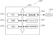
- the motion sickness determination apparatus 1000 shown in FIG. 28 includes a CPU (Central Processing Unit) 1002 and a RAM 1003.
- the CPU 1002 and the RAM 1003 are connected to each other via a bus 1005, and are also connected to other components of the sickness state determination device 1000 via the bus 1005.
- the CPU 1002 controls and calculates the sickness state determination device 1000. Any processor can be used as the CPU 1002.
- the function of the control unit 11 of the sickness state determination device 10 described with reference to FIG. 3 can be realized by the CPU 1002, for example.
- the RAM 1003 includes, for example, a cache memory and a main memory, and can temporarily store programs and the like used by the CPU 1002.
- the motion sickness determination apparatus 1000 may include a disk 1004, a communication device 1006, a motion sensor 1007, and a motion sickness control unit (for example, a current applying device) 1008.
- a drive may be connected to the bus 1005 for any of these components, if necessary.
- the disk 1004 includes an operating system (for example, WINDOWS (registered trademark), UNIX (registered trademark), or LINUX (registered trademark)), a program for realizing a sickness state determination method according to the present technology, and various other types. Programs and various data can be stored.
- the communication device 1006 connects the motion sickness determination device 1000 to the network 1010 by wire or wirelessly.
- the communication device 1006 acquires various data (for example, a database (particularly a cloud database), data transmitted from the biometric information acquisition device 20 and the surrounding environment information device 30) from the motion sickness determination device 1000 via the network 1010. be able to.
- the acquired data can be stored in the disc 1004, for example.
- the type of the communication device 1006 may be appropriately selected by those skilled in the art.
- the disk 1004 may be, for example, a semiconductor recording medium such as a flash memory and is not limited to this.
- the motion sensor 1007 may acquire the motion information used to acquire the second motion sickness index.
- the drive can read the information recorded on the recording medium and output it to the RAM 1003.
- the recording medium is, for example, a microSD memory card, an SD memory card, or a flash memory, but is not limited to these.
- the biometric information acquisition device 20 is preferably capable of acquiring biometric information that appears or fluctuates when the subject is or is in a state of intoxication.
- the biological information is, for example, information about the enzyme derived from the subject (for example, the amount of enzyme and enzyme activity), respiration information (for example, respiration rate, inhalation time, and exhalation time), complexion information (for example, degree of paleness of face) Etc.), saliva amount information, sweating information (eg cold sweat, sweating rate, presence or absence of sweating), blood pressure information (eg systolic blood pressure and diastolic blood pressure), and heartbeat information (eg heart rate). It may be one or a combination of two or more.
- the biometric information acquired by the biometric information acquisition device 20 includes information regarding the enzyme derived from the subject, and more preferably includes information regarding the activity and/or amount of the enzyme derived from the subject. More preferably, the enzyme may be amylase.
- the biological information may be amylase activity and/or amylase amount in saliva of the subject.
- the amylase activity and the amount of amylase in saliva are preferable for downsizing the devices that make up the sickness determination system, and are also preferable for accurate sickness determination.
- the device compact because it detects facial pallor, and it is also difficult to make the device wearable.
- it is difficult to distinguish cold sweat from environmental sweat Further, a large amount of sweat is required to determine that it is cold sweat by analyzing the sweat component, so it is difficult to make a device for detecting cold sweat compact, and it is also difficult to make it a wearable device. Is.
- the biological information acquisition device 20 preferably includes an enzyme sensor, and more preferably an amylase sensor.
- the information about the enzyme can be obtained by preferably an enzyme sensor, more preferably a device for measuring the amount and/or activity of the enzyme.
- the enzyme sensor for example, the enzyme sensor described in International Publication No. WO2018/066227 mentioned above may be used.
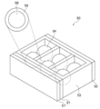
- FIGS. 4A, 4B, and 4C the enzyme sensor will be described with reference to FIGS. 4A, 4B, and 4C.
- FIG. 4A is a schematic view of an example of the enzyme sensor.
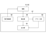
- FIG. 4B is a block diagram of an example of the enzyme sensor.
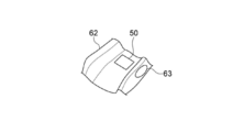
- FIG. 4C is a diagram showing a configuration example of the enzyme sensor.
- an enzyme sensor 50 (measuring device for measuring the amount and/or activity of an enzyme) 50 includes a pair of electrodes 51 and 52, an electron transfer layer 53 sandwiched between the pair of electrodes 51 and 52, and a detection target.
- the film includes at least one enzyme other than the enzyme to be detected in a film containing at least the substrate of the enzyme, and the electron generating capsule 54 is in contact with the electron transfer layer 53.
- the electron generating capsule 54 may be retained inside the electron transport layer 53, as shown in FIG. 4A.
- the enzyme sensor 50 may include the logic unit 57.
- the pair of electrodes 51 and 52 function as an output unit that takes out the electrons generated by the reaction with the enzyme to be detected as a detection signal. Specifically, the pair of electrodes 51 and 52 can take out the electrons generated in the electron generating capsule 54 via the electron transfer layer 53 by applying a voltage between the electrodes.
- the pair of electrodes 51 and 52 may be formed of a conductive material. These electrodes may be provided as a pair of parallel flat plates that sandwich the electron transfer layer 53.
- the pair of electrodes 51 and 52 is, for example, a simple substance of metal such as copper (Cu), silver (Ag), platinum (Pt), aluminum (Al), tungsten (W), and titanium (Ti), or It may be formed of an alloy, or it may be formed of a carbon material such as graphite and amorphous carbon. More preferably, the pair of electrodes 51 and 52 is formed of a metal simple substance or an alloy or a carbon material that is unlikely to cause corrosion such as rust so that the measuring device 50 is more suitable for use in an environment where the measuring device 50 is in contact with body fluid. Can be done.
- One of the pair of electrodes 51 and 52 functions as an anode and the other functions as a cathode, but the polarities of the pair of electrodes 51 and 52 may be appropriately set depending on the direction in which the detection signal is taken out.
- the electron transfer layer 53 is in contact with the electron generating capsule 54 and is sandwiched by the pair of electrodes 51 and 52.
- the electron transfer layer 53 transfers the electrons generated by the electron generation capsule 54 to one of the electrodes 51 and 52 (that is, the anode).
- the electron transfer layer 53 may include an electron transfer mediator.
- the electron transfer mediator may be, for example, an electrolyte capable of accepting electrons, and the electrolyte may transfer the electrons to the anode side of the electrodes 51 and 52.
- the electron transfer layer 53 may be formed, for example, by gelling a solution containing an electrolyte, that is, a gelled product of an electrolyte-containing solution.
- the electrolyte contained in the electron transfer layer 53 may be a known substance capable of reversibly accepting and releasing electrons.
- a substance containing ferricyanide ion may be used, and examples thereof include potassium ferricyanide.
- the ferricyanide ion ([Fe(CN) 6 ] 3 ⁇ ) can be reversibly converted to the ferrocyanide ion ([Fe(CN) 6 ] 4 ⁇ ) by a redox reaction.
- the ferricyanide ion ([Fe(CN) 6 ] 3 ⁇ ) accepts an electron by changing to a ferrocyanide ion ([Fe(CN) 6 ] 4 ⁇ ), and any of the electrodes 51 and 52 is Then, the electrons can be emitted by returning to the ferricyanide ion ([Fe(CN) 6 ] 3 ⁇ ).
- electron transfer mediators include benzoquinone.
- At least one concave structure may be provided on the surface not sandwiched by the pair of electrodes 51 and 52, and the electron generating capsule 54 may be held in the concave structure.
- the electron transfer layer 53 can reliably hold the electron generating capsule 54.
- the concave structure can increase the contact area between the electron transfer layer 53 and the electron generation capsule 54.
- a plurality of concave structures may be provided in the electron transfer layer 53, and a plurality of electron generating capsules 54 may be held in the concave structure.
- the contact area between the electron transfer layer 53 and the electron generating capsule 54 can be increased.
- the number of electron generating capsules 54 in the concave structure the number of reaction sites between the enzyme and the electron generating capsules 54 can be increased.
- the number of concave structures provided in the electron transfer layer 53 and the number of electron generating capsules 54 provided inside the concave structure may be appropriately set.
- the electron generation capsule 54 has a reaction site that generates electrons by an enzymatic reaction with the detection target enzyme, and generates electrons according to the amount of the detection target enzyme.
- the electron generation capsule 54 has a structure in which an outer membrane 55 containing at least a substrate of an enzyme to be detected and an inner solution 56 containing at least one kind of enzyme other than the detection target are included.
- the outer membrane 55 contains a substrate of an enzyme to be detected and functions as a reaction site of the enzyme to be detected and the enzyme sensor 50. Therefore, the shape of the electron generating capsule 54, the shape of which is defined by the outer film 55, may be substantially spherical so that the surface area of the reaction site with the enzyme to be detected is larger.
- the outer membrane 55 serves to retain the inner solution 56 inside the electron generating capsule 54 so that the inner solution 56 does not leak outside the enzyme sensor 50. Therefore, in order to increase the strength of the outer membrane 55, in addition to the substrate of the enzyme to be detected, the outer membrane 55 may contain membrane constituents such as lipids, proteins, and carbohydrates.
- the enzyme contained in the inner solution 56 may contain at least an oxidase.
- the substrate of the oxidase is a product produced by an enzyme reaction of at least one step of the substrate contained in the outer membrane 55.
- the oxidase can take out an electron from the product by oxidizing the product generated by the reaction of the enzyme to be detected.
- the enzyme contained in the inner solution 56 may include an enzyme having a product of the reaction between the enzyme to be detected and the substrate contained in the outer membrane 55 as a substrate. At this time, the oxidase contained in the inner solution 56 uses the enzyme to be detected and the final product of the multi-step reaction of the enzyme contained in the inner solution 56 as a substrate.
- the inner solution 56 may further include a solvent that dissolves the enzyme (for example, water) and a functional polymer that stabilizes the enzyme.
- the inner solution 56 may further include an aqueous dispersion solution of PMEH (copolymer of 2-methacryloyloxyethylphosphorylcholine and 2-ethylhexyl methacrylate), which has high biocompatibility.
- the reaction between the electron generating capsule 54 and the enzyme to be detected proceeds as follows.
- the enzyme to be detected reacts with the substrate contained in the outer membrane 55 to generate an enzymatic reaction product of the substrate.
- the generated enzymatic reaction product is oxidized by the oxidase contained in the inner solution 56 oozing from the inside due to the difference in osmotic pressure, and releases an electron.
- the emitted electrons are received by the electrolyte contained in the electron transfer layer 53, and taken out from either of the electrodes 51 and 52 as described above.
- the outer membrane 55 of the electron generating capsule 54 may be configured to include at least starch that is a substrate of amylase, and the inner solution 56 includes at least maltase and glucose oxidase. May be composed of
- the amylase to be detected reacts with the starch contained in the outer membrane 55 to produce maltose.
- maltose contained in the inner solution 56 oozing to the outer membrane 55 due to the difference in osmotic pressure reacts with maltose to produce glucose.
- the glucose oxidase contained in the inner solution 56 and glucose react with each other, so that electrons are taken out from the glucose.
- the electrons extracted from glucose are accepted by the electron transfer mediator such as ferricyanide ion contained in the electron transfer layer 53.
- ferricyanide ions accept electrons to become ferrocyanide ions.
- the enzyme sensor 50 may further include an ion exchange membrane that covers at least the opening of the electron transfer layer 53 having the concave structure.
- the ion exchange membrane prevents the electron generating capsule 54, the constituent components of the electron generating capsule 54, or the constituent components of the electron transfer layer 53 from flowing out from the enzyme sensor 50 into the body fluid.
- the ion exchange membrane may include a cation to prevent leakage of the anion included in the electron transfer layer 53. It may be an exchange membrane.
- the electrolyte contained in the electron transfer layer 53 is a cation, the ion exchange membrane may be an anion exchange membrane.
- the enzyme sensor 50 may further include a logic unit 57.
- the logic unit 57 may include, for example, a voltage control unit 58, a detection unit 59, an alert unit 60, and an output unit 61.
- the logic unit 57 can be realized by cooperation of hardware such as CPU (Central Processing Unit), RAM (Random Access Memory), and ROM (Read Only Memory), and software that controls the operation of each component.
- CPU Central Processing Unit
- RAM Random Access Memory
- ROM Read Only Memory
- the voltage control unit 58 controls the voltage applied between the pair of electrodes 51 and 52 of the enzyme sensor 50 in order to measure the amount of enzyme to be detected. Specifically, the voltage controller 58 controls the voltage so that a rectangular pulse voltage is applied between the pair of electrodes 51 and 52.
- the detection unit 59 detects the amount of the enzyme to be detected by measuring the current flowing between the pair of electrodes 51 and 52 of the enzyme sensor 50. Specifically, when a rectangular pulse voltage is applied between the electrodes 51 and 52 by the voltage control unit 58, the electrolyte (for example, ferrocyanide ion) that has accepted the electrons of the electron transfer layer 53 is on the anode side. It emits electrons to the electrodes and returns to the electrolyte that has not accepted the electrons (eg, ferricyanide ion). At this time, a current flows between the pair of electrodes 51 and 52 due to the emitted electrons.
- the electrolyte for example, ferrocyanide ion
- the detection unit 59 can detect the amount of the electrolyte (for example, ferrocyanide ion) that has accepted the electrons by detecting the magnitude of the current flowing between the pair of electrodes 51 and 52. Further, since the amount of the electrolyte (for example, ferrocyanide ion) that has received the electron depends on the reaction amount between the enzyme to be detected and the electron generating capsule 54, the detecting unit 59 is arranged between the pair of electrodes 51 and 52. The amount of the enzyme to be detected can be calculated from the magnitude of the current flowing in the.
- the electrolyte for example, ferrocyanide ion
- the alert unit 60 monitors the consumption amount of the substrate contained in the outer film 55 of the electron generating capsule 54, and determines the replacement timing of the enzyme sensor 50.
- the substrate contained in the outer film 55 of the electron generating capsule 54 is consumed by the reaction with the enzyme to be detected, and thus decreases as the measurement by the enzyme sensor 50 progresses. Therefore, in order to continue the measurement by the enzyme sensor 50, it is required to replace the enzyme sensor 50 before all the substrates contained in the outer membrane 55 of the electron generating capsule 54 are consumed.
- the alert unit 60 determines the replacement timing of the enzyme sensor 50 based on the integrated value of the measured currents detected by the detection unit 59. Further, the alert unit 60 may notify the target to replace the enzyme sensor 50 by display, voice, or signal via the output unit 61.
- the secretion of the enzyme in the target organism is shown by showing the activity of the enzyme by increasing or decreasing the ratio to the amount of the enzyme in normal times as described above. It is possible to more accurately indicate the extent of quantity.
- the output unit 61 may output the current value detected by the detection unit 59 instead of the activity of the enzyme to be detected.
- the activity of the enzyme to be detected may be calculated by another device that has acquired the output current value (for example, a sickness state determination device described below).
- the output unit 61 outputs information to an external display device or audio output device via, for example, a wired or wireless LAN (Local Area Network), Bluetooth (registered trademark), or Wi-Fi (registered trademark). May be.
- a wired or wireless LAN Local Area Network
- Bluetooth registered trademark
- Wi-Fi registered trademark
- the enzyme sensor 50 may be mounted on the mouthpiece 62, for example, as shown in FIG. 4C.
- various modules such as an acceleration sensor, a GNSS (Global Navigation Satellite System) sensor, an RF (Radio Frequency) module, a power generation module, and a power storage module may be mounted on the mouthpiece 62.
- An orifice 63 may be formed in the mouthpiece 62 so that the enzyme sensor 50 and saliva can come into contact with each other.
- the motion information is motion information related to a movement of the body of the target, in particular, a movement of the head
- the surrounding environment information is video information related to an image visually perceived by the target.
- the second index acquisition unit may acquire the second motion sickness index based on the motion information and the video information.
- the movement information is first acceleration information based on a movement of the target body
- the surrounding environment information is second acceleration information based on an image visually perceived by the target.
- the second index acquisition unit can acquire the second motion sickness index based on the first acceleration information and the second acceleration information.
- the second index acquisition unit may acquire the difference between the first acceleration information and the second acceleration information as the second motion sickness index.
- the ambient environment information is odor information regarding an odor that the object perceives by the sense of smell
- the second index acquisition unit based on the odor information, the second sickness Status indicators can be obtained.
- the second index acquisition unit may acquire the intensity of a predetermined type of odor as the second sickness state index.
- the system may further include a sickness state control unit that presents an odor to the target or removes a scent around the target based on the determination result of the sickness state determination unit. This embodiment will be described in more detail below with reference to the system configuration example and the determination processing flow in (7).
- the sickness state determination system may further include an output unit that outputs the determination result of the sickness state determination unit.
- the output unit can output the determination result by an information transmission medium such as an image, a sound, or a printed matter. By outputting via these media, it is possible to inform the subject that he or she is in a sick state.
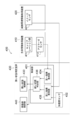
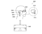
- FIG. 5 shows a block diagram of the motion sickness determination system of this example
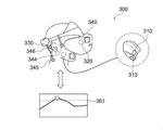
- FIG. 6 shows a configuration example of the motion sickness determination system of this example
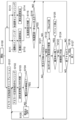
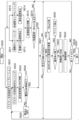
- FIG. 7 shows an example of the flow of the sickness state determination processing by the system.
- the first index acquisition unit acquires the amylase activity in saliva as the first sickness state index
- the second index acquisition unit the movement information regarding the movement of the head of the target and the target visually.
- the difference in acceleration acquired based on the surrounding image information perceived by is acquired as a second motion sickness state index.
- the sickness may vary depending on individual subjects, and may vary depending on the physical condition of the same subject. Therefore, by performing the sickness state determination in real time by the sickness state determination system of the present technology, it is possible to more accurately determine and control the sickness state.
- a sickness state determination system 100 includes a biological information acquisition device (amylase detection device) 110 that measures amylase activity in saliva and an image visually recognized by an object using the system.
- a surrounding environment information acquisition device (video acquisition device) 120 and a motion sickness determination device 130 are included.
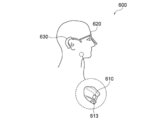
- the biometric information acquisition device 110 is attached to the inside of the target's oral cavity so that it can contact saliva in the target's oral cavity.
- the ambient environment information acquisition device 120 is mounted near the eye of the target so that the image viewed by the target can be acquired.
- the surrounding environment information acquisition device 120 may have a shape such as eyewear, as shown in FIG.
- the motion sickness determination device 130 may be mounted on the target's head so as to perform the same movement as the target's head, and is preferably mounted near the target's ear. By being mounted near the ears, the acceleration sensor 132 in the motion sickness determination device 130 can detect a movement closer to the movement sensed by the target vestibular organ.
- the biological information acquisition device 110 includes a calibration unit 111 and an amylase sensor 112.
- the biological information acquisition device 110 further includes a communication unit (not shown), and is configured to be capable of wired or wireless communication with the sickness state determination device 130 by the communication unit.
- the biometric information acquisition device 110 is configured as a partial mouthpiece, and more specifically, as a mouthpiece attached to the back teeth.
- the amylase sensor 112 is arranged inside the mouthpiece (the surface facing the teeth or gums when worn).
- the mouthpiece is provided with an orifice 113 so that the amylase sensor 112 can come into contact with saliva.
- the calibration unit 111 performs calibration for measuring the amylase activity by the amylase sensor 112.
- the calibration unit 111 can cause the amylase sensor 112 to perform a calibration process for acquiring a reference amylase activity immediately after or before the start of the determination by the sickness state determination system 100.
- the amylase sensor 112 is the enzyme sensor described in “(1-2) Details of first embodiment” above. Since the description applies to the amylase sensor 112, the description of the amylase sensor 112 is omitted.
- the amylase sensor 112 can preferably monitor in real time.
- the surrounding environment information acquisition device 120 includes an image sensor 121.
- the ambient environment information acquisition device 120 further includes a communication unit (not shown), and is configured to be capable of wired or wireless communication with the sickness state determination device 130 by the communication unit.
- the surrounding environment information acquisition device 120 may be configured as eyewear.
- the image sensor 121 is configured to be able to acquire an image similar to the external landscape visually perceived by the subject wearing the eyewear.
- the image sensor 121 may be, for example, a CMOS or CCD, or may be an IR (infrared) sensor.
- the motion sickness determination device 130 includes a control unit 131, an acceleration sensor 132, and a motion sickness control unit 133.
- the control unit 131 includes a first index acquisition unit 134, a second index acquisition unit 135, and a sickness state determination unit 136.
- the motion sickness determination device 130 may include a communication unit (not shown).
- the communication unit is configured to be capable of communicating with the biological information acquisition device 110 and the surrounding environment information acquisition device 120 by wire or wirelessly, more preferably by wireless (for example, Bluetooth (registered trademark)).
- the first index acquisition unit 134 acquires the amylase activity acquired by the amylase sensor 112 as the first sickness state index.
- the acceleration sensor 132 may be, for example, a triaxial acceleration sensor.
- the acceleration sensor 132 detects the movement of the target body, particularly the movement of the head.
- the second index acquisition unit 135 receives the video information acquired by the surrounding environment information acquisition device 120.
- the second index acquisition unit 135 acquires acceleration from the video information.
- the acceleration can be, for example, acceleration in three axis directions.
- the direction of the acquired acceleration may preferably correspond to the direction of the acceleration detected by the acceleration sensor 132. This makes it possible to acquire a more appropriate acceleration difference as the second motion sickness index.
- the second index acquisition unit 135 calculates the acceleration difference between the two accelerations based on the first acceleration acquired from the image information acquired by the surrounding environment information acquisition device 120 and the second acceleration acquired by the acceleration sensor 132. It is acquired as a motion sickness index.
- the sickness state determination unit 136 determines whether or not the target is in a sickness state based on the first sickness state index and the second sickness state index.
- the motion sickness determination unit 136 may have a first threshold and a second threshold to be compared with the first motion sickness index and the second motion sickness index, respectively.
- the sickness state determination unit 136 when the first sickness state index is equal to or higher than the first threshold value and the second sickness state index is equal to or higher than the second threshold value, the subject becomes a sickness state or a sickness state. It can be determined that. Further, the motion sickness determination unit 136 determines that the first motion sickness index is not greater than or equal to the first threshold, the second motion sickness index is not greater than or equal to the second threshold, or the first motion sickness index.
- the second sickness state index is neither above the first threshold value nor above the second threshold value, it can be determined that the subject is not in a sickness state or not in a sickness state.
- the sickness state control unit 133 is configured to be able to apply a current to the target's head (particularly the vestibular organ of the inner ear).
- the motion sickness control unit 133 is arranged near the right ear, and the motion sickness control unit (not shown) is also arranged near the left ear.
- the sickness state control unit 133 disposed near the right ear has three electrodes 144, 145, and 146 as shown in FIG. These electrodes are, for example, near the temples, under the ear (or mastoid) (eg, 2 cm to 10 cm below, particularly 4 cm to 8 cm below, more particularly about 6 cm below) the neck, and near the mastoid. They can be placed in different places.
- the motion sickness state control unit arranged near the left ear is also arranged at three places.
- the GVS using the electrodes arranged in this way makes it possible to give an illusion of acceleration to the brain, which makes it possible to control a sickness state.
- the sickness state determination device 130 may be connected to the database 140 so as to be communicable by wire or wirelessly.
- the database 140 may be, for example, a cloud database.
- the database 140 can store various data described in (2-2) below.
- the database 140 can be updated at any time.
- step S100 of FIG. 7 the sickness state determination system 100 starts the sickness state determination process.
- the sickness state determination device 130 is activated in response to the start signal of the process input by the target, and the sickness state determination device 130 activates the biological information acquisition device 110 and the surrounding environment information acquisition device 120.
- a signal for causing the device to be transmitted is transmitted to each of these devices. These devices are activated in response to receiving the signal.
- the biological information acquisition device 110 (in particular, the calibration unit 111) can cause the amylase sensor 112 to perform a calibration process for acquiring a reference amylase activity.
- the amylase sensor 112 can automatically measure the amylase activity for several minutes, and a reference value can be set based on the measurement result.
- the biological information acquisition device 110 acquires amylase activity information.
- the biological information acquisition device 110 measures the amylase activity S in the saliva of the target as the amylase activity information. The measurement can preferably be performed in real time.
- the biological information acquisition device 110 transmits the acquired amylase activity information to the motion sickness determination device 130 through the communication unit.
- the motion sickness determination device 130 receives amylase activity information from the biological information acquisition device 110.
- the first index acquisition unit 134 of the sickness state determination device 130 calculates, for example, a variation rate dS/dt of the amylase activity S with respect to time from the received amylase activity information.
- the variation rate can be used by the motion sickness determination unit 136 as the first motion sickness index.
- the amylase activity S itself may be used by the motion sickness determination unit 136 as a first motion sickness index. That is, in step S103, the first index acquisition unit 134 can acquire the fluctuation rate or the amylase activity level as the first sickness state index.
- step S104 the control unit 131 (for example, the motion sickness determination unit 136) determines whether the fluctuation rate or the amylase activity is equal to or higher than a threshold value.
- the threshold used for the determination in step S104 will be referred to as the first threshold.
- the first threshold value may be set in advance or may be updated at any time.
- the first threshold value may be set or updated based on data stored in, for example, the database 140, more specifically, the cloud database.
- the data used for the setting or updating for example, one or more selected from the amylase activity information of the target measured in the past, the past sickness determination result performed on the target, and the physical information of the target is used.
- step S104 when the variation rate or the amylase activity is equal to or higher than the first threshold value, the control unit 131 advances the process to step S105. When the fluctuation rate or the amylase activity is less than the threshold value, the control unit 131 advances the process to step S121.
- FIG. 8 is a graph showing an example of changes in the amylase activity S.
- the amylase activity S gradually increases from the reference value S 0 set in step S101. Then, at time t1, the amylase activity S reaches the first threshold value S 1 .
- a region having an amylase activity of S 1 or more is referred to as a current application region, and when the amylase activity is within this region, it is determined that the current can be applied to the target. Since the amylase activity S is less than the first threshold value S 1 until time t1, in step S104, the sickness state determination unit 136 advances the process to step S121.
- step S104 the motion sickness determination unit 136 advances the process to step S105.
- the amylase activity S decreases by applying the current described below, for example.
- the amylase activity S becomes less than the first threshold value S 1 .
- the amylase activity S is less than the first threshold value S 1 , so in step S104, the sickness state determination unit 136 advances the process to step S121.
- step S105 the process is returned to step S102, and the processes of steps S102 to S104 can be performed again.
- Steps S102 to S105 are preferably repeated, more preferably in real time. Further, if steps S102 to S104 are performed while the sickness state control unit 133 is applying a current to the target, the sickness state control unit 133 stops application of the current in step S105.
- the surrounding environment information acquisition device 120 acquires an image of the external landscape.
- the image includes at least a part of the external scenery viewed by the object, and may include at least the external scenery in the line-of-sight direction of the object. More specifically, the acquisition of the video can be performed by the image sensor 121.
- the ambient environment information acquisition device 120 transmits the acquired video information to the motion sickness determination device 130 through the communication unit.
- the motion sickness determination device 130 receives the video information from the surrounding environment information acquisition device 120.
- the second index acquisition unit 135 of the motion sickness determination device 130 detects or calculates the acceleration based on the received video information.
- the acceleration acquired based on the image in step S112 will be referred to as “first acceleration”.
- the first acceleration corresponds to the acceleration based on the image viewed by the target.
- the first acceleration may be acceleration in one or two directions selected from, for example, an acceleration in the front-rear direction, an acceleration in the left-right direction, and an acceleration in the up-down direction, or acceleration in these three directions. May be all.
- step S113 the acceleration sensor 132 included in the motion sickness determination device 130 detects acceleration.
- the acceleration detected by the acceleration sensor in step S113 is referred to as "second acceleration".
- the second acceleration corresponds to the acceleration sensed by the vestibular organ of the subject.
- the acceleration sensor 132 transmits the detected second acceleration to the second index acquisition unit 135.
- the second index acquisition unit 135 acquires the second acceleration detected by the acceleration sensor 132.
- the second acceleration may be, for example, one or two accelerations selected from the longitudinal acceleration, the lateral acceleration, and the vertical acceleration of the target, or all of these three accelerations. May be.
- the direction of the second acceleration may correspond to the direction of the first acceleration acquired in step S112.
- step S115 the second index acquisition unit 135 calculates the difference between the first acceleration acquired in step S112 and the second acceleration acquired in step S113. Preferably, the difference between accelerations in the same direction is determined.
- the second index acquisition unit 135 acquires the difference as a second motion sickness index.
- step S116 the motion sickness determination unit 136 determines whether the difference obtained in step S115 is equal to or greater than a threshold value.
- the threshold value used for the determination in step S116 is referred to as a second threshold value.
- the second threshold value may be set in advance or may be updated at any time.
- the second threshold value may be set or updated based on the data stored in, for example, the database 140, more specifically, the cloud database.
- the data used for the setting or update is selected from, for example, the difference between the first acceleration and the second acceleration acquired in the past, the past sickness determination result performed on the target, and the physical information of the target. One or more may be used.
- step S116 if the difference between the first acceleration and the second acceleration is greater than or equal to the second threshold, the motion sickness determination unit 136 proceeds with the process to step S121. If the difference is less than the second threshold, the process is returned to steps S111 and S113, and the processes of steps S111 and S113 can be performed again.
- step S121 the motion sickness determination unit 136 determines that the fluctuation rate or the amylase activity is equal to or higher than the first threshold value and the difference between the first acceleration and the second acceleration is equal to or higher than the second threshold value. Determine whether.
- the motion sickness determination unit 136 It is determined that the target is in a sickness state or is in a sickness state, and the process proceeds to step S122.
- a sickness state The determination unit 136 determines that the target is not in a sickness state or not in a sickness state, and the process is returned to steps S102, S111, and S113.
- the control unit 131 can select, for example, an electrode through which a current is applied and/or a magnitude of the current.
- the electrode to which the current is applied can be selected based on, for example, the difference between the first acceleration and the second acceleration.
- the electrodes corresponding to the direction in which the first acceleration and the second acceleration have a difference can be selected. For example, when there is a difference in acceleration in the vertical direction of the object, the electrode near the mastoid and the electrode on the neck are selected as the electrodes to which a current is applied.
- the electrodes near the left and right temples are selected as the electrodes to which the current should be applied.
- the electrode near the mastoid and the electrode near the temple are selected as the electrodes to which current is applied.
- the electrode corresponding to the direction with the largest difference is selected.
- the magnitude of the applied current can be selected based on, for example, the variation rate dS/dt of the amylase activity S or the amylase activity S.
- the magnitude of the applied current may be dS/dt ⁇ C.
- C is a correction term, which may be, for example, a preset value, or may be derived based on the data in the database 140 (particularly the cloud database). C may be corrected to be larger when the degree of decrease in the amylase activity S due to the applied current is small, or may be corrected to be smaller when the degree of decrease is large. May be done.
- the magnitude of the applied current may be, for example, 0.01 mA to 3 mA, more preferably 0.1 mA to 2 mM, and even more preferably 0.5 mA to 1.5 mA. A current within this numerical range is suitable for suppressing or preventing a sickness condition.
- the applied current is preferably 5 Hz or less, more preferably 3 Hz or less, and even more preferably 2 Hz or less. As a result, a gentle current is applied to the subject, and the subject can be prevented from feeling a tingling pain due to the current.
- a current is applied from a database (in particular, a cloud database) A having a data object regarding an object and/or a database (especially a cloud database) B having data regarding a human other than the object.
- the electrode and/or the magnitude of the applied current may be retrieved.
- the database A includes, for example, the physical information of the target (for example, sex, age, height, and weight), the past sickness state determination result about the target, the current application history, the relationship between the acceleration difference and the amylase activity fluctuation, and the applied data. It may include one or more data selected from the current and the response of amylase activity by the current. As shown in FIG.
- the database B stores the physical information (for example, sex, age, height, and weight) of each person other than the target, the past sickness state determination result about the person other than the target, and the current application history. , One or more data selected from the relationship between the acceleration difference and the amylase activity fluctuation, and the response of the applied current and the amylase activity by the current. For example, when the subject uses the sickness state determination system of this example for the first time, data of the sickness state determination result regarding the subject is not accumulated. Therefore, data about another person such as the database B can be used.
- the physical information for example, sex, age, height, and weight
- the electrode to which the current is applied and/or the current applied can be selected.
- a database may be stored in database 140.
- step S123 the control unit 131 determines whether or not the magnitude of the current selected in step S122 exceeds the upper limit value.
- the upper limit value may be set in advance or may be appropriately changed depending on the target.
- the upper limit value can be, for example, 3 mA, 4 mA, or 5 mA.
- the control unit 131 advances the process to step S124.
- the control unit 131 advances the process to step S125.
- control unit 131 may generate an error and stop the sickness state determination device 130.
- the error can be notified to the target by audio or video, for example. Further, the biological information acquisition device 110 and/or the surrounding environment information acquisition device 120 may be stopped along with the stoppage of the sickness state determination device 130.
- step S124 the control unit 131 may drive the sickness state control unit 133 to apply a current stimulus to the target.
- the sickness state control unit 133 can apply the current of the magnitude selected in the step S123 to the electrode selected in the step S123, for example. This may apply a current to the vestibular organ of the subject. Thereby, the difference between the first acceleration and the second acceleration can be reduced or eliminated, and it is possible to prevent a sickness state or suppress a sickness state.
- the application of the current may be stopped, for example, after a lapse of a predetermined time, or may be stopped in response to dS/dt or S becoming less than the first threshold value.
- the processes of steps S102, S111, and S113 may be performed again. Alternatively, the processes of steps S102, S111, and S113 may be performed again while the current is being applied.
- the control unit 131 advances the process to step S126.
- FIG. 8 is as described above.
- FIG. 11 is a diagram showing an example of changes in the applied current.
- the amylase activity S becomes equal to or higher than the first threshold value S1. Therefore, a current can be applied.
- the current value may gradually increase from 0 mA to the selected current value A1. As a result, it is possible to prevent the subject from feeling pain due to the electric current.
- the current value may be set so as not to exceed the upper limit value mentioned regarding step S123. Therefore, for example, as shown in FIG.
- step S126 the control unit 131 determines whether to end the motion sickness determination process. For example, when a signal corresponding to the operation for ending the process is detected, it is determined that the process is ended. When it is determined that the process is to be ended, the control unit ends the process. If the signal is not detected, the control unit 131 may return the processing to steps S102, S111, and S113, and the sickness state determination processing may be repeated again. As described above, in the present technology, the motion sickness determination process is repeated, and more preferably performed in real time. The ease of getting sick differs depending on the individual subject, and may differ depending on the physical condition of the same subject. By repeating the sickness state determination process, more preferably by performing the process in real time, it is possible to more accurately determine the sickness state and control the sickness state.
- the sickness state can be appropriately determined when the target is in a vehicle or an aircraft, for example. Since the sickness state determination system of this example can appropriately determine the sickness state as described above, it is also possible to notify the subject that the sickness state is or will be, for example. For example, when the occupants of these vehicles are reading or watching TV, the acceleration difference may cause a sickness. The above notification can prompt the occupant to stop reading or watching TV. Further, since the sickness state determination system of the present example can apply an appropriate stimulus (current) according to the acceleration difference to the target, it is possible to prevent a sickness state or suppress a sickness state.
- FIG. 12 A block diagram of the sickness state determination system of this example is shown in FIG. 12, and a configuration example of the system is shown in FIG. Further, FIG. 14 shows an example of the flow of the sickness state determination processing by the system.
- the first index acquisition unit acquires the amylase activity in saliva as the first sickness state index
- the second index acquisition unit the movement information regarding the movement of the head of the target and the target.
- the difference in acceleration obtained based on the ambient image information perceived visually is obtained as a second sickness state index.
- a sickness state determination system 200 includes a biological information acquisition device (amylase detection device) 210 that measures an amylase activity in saliva, and an image visually recognized by an object using the system.
- a surrounding environment information acquisition device (video acquisition device) 220 and a sickness state determination device 230 to be acquired are included.
- the biometric information acquisition device 210 is attached to the inside of the target's oral cavity so that it can contact saliva in the target's oral cavity.
- the ambient environment information acquisition device 220 and the motion sickness determination device 230 are included in the display device (for example, VR viewing device) 240 as its components.
- the display device 240 is connected to an information processing device (for example, a game device) 250 by wire or wirelessly.
- the display device 240 may display a video (for example, a VR video) based on the data transmitted from the information processing device 250.
- the ambient environment information acquisition device 220 is configured to be able to acquire the image viewed by the target.
- the motion sickness determination device 230 may be mounted on the target's head so as to perform the same movement as the target's head, and is preferably mounted near the target's ear. By being worn near the ears, the acceleration sensor 232 in the motion sickness determination device 230 can detect a movement closer to the movement sensed by the target vestibular organ.
- the biological information acquisition apparatus 210 and its constituent elements are the same as the biological information acquisition apparatus 110 and its constituent elements described in “(2-1) Description of the configuration of the sickness state determination system of the first example” in (2) above. And the description also applies to this example.
- the surrounding environment information acquisition device 220 acquires the video information presented to the target by the display device 240.
- the motion sickness determination device 230 includes a control unit 231, an acceleration sensor 232, and a motion sickness control unit 233.
- the control unit 231 includes a first index acquisition unit 234, a second index acquisition unit 235, and a sickness state determination unit 236.
- the sickness state determination device 230 includes a communication unit (not shown), and is configured to be capable of wired or wireless communication with the biological information acquisition device 210 and the surrounding environment information acquisition device 220 by the communication unit. ..
- the sickness state determination device 230 and its components are the same as the sickness state determination device 130 and the configuration thereof described in the above (2) “(2-1) Description of the configuration of the sickness state determination system of the first example”. It is the same as the element, and its description also applies to this example.
- step S200 of FIG. 14 the sickness state determination system 200 starts the sickness state determination process.
- the motion sickness determination device 230 is activated in response to the start signal of the process input by the target, and the motion sickness determination device 230 activates the biological information acquisition device 210 and the surrounding environment information acquisition device 220.
- a signal for causing the device to be transmitted is transmitted to each of these devices. These devices are activated in response to receiving the signal. Alternatively, all of the devices included in the sickness state determination system 200 may be activated in response to activation of the display device 240.
- Steps S201 to S205 are the same as steps S101 to S105 described in “(2-2) Description of an example of determination processing by the sickness state determination system of the first example” in (2) above. Since the description also applies to this example, the description of steps S201 to S205 will be omitted.
- the surrounding environment information acquisition device 220 acquires a video (for example, a game video) presented to the target by the display device 240.
- the image includes at least a part of an image presented to the target, and may include at least an image in the line-of-sight direction of the object among the images presented to the target.
- the ambient environment information acquisition device 220 transmits the acquired video information to the motion sickness determination device 230 through the communication unit.
- the motion sickness determination device 230 receives the video information from the ambient environment information acquisition device 220.
- the second index acquisition unit 235 of the motion sickness determination device 230 detects acceleration based on the received video information.
- the acceleration detected based on the image in step S212 will be referred to as “first acceleration”.
- the first acceleration corresponds to the acceleration based on the image viewed by the target.
- the first acceleration may be acceleration in one or two directions selected from, for example, an acceleration in the front-rear direction, an acceleration in the left-right direction, and an acceleration in the vertical direction of the target, or all of these three accelerations. May be
- step S213 the acceleration sensor 232 included in the motion sickness determination device 230 detects acceleration.
- the acceleration detected by the acceleration sensor in step S213 is referred to as "second acceleration".
- the second acceleration corresponds to the acceleration sensed by the vestibular organ of the subject.
- the second index acquisition unit 235 acquires the second acceleration detected by the acceleration sensor 232.
- the second acceleration may be, for example, one or two accelerations selected from the longitudinal acceleration, the lateral acceleration, and the vertical acceleration of the target, or all of these three accelerations. May be.
- the direction of the second acceleration may correspond to the direction of the first acceleration acquired in step S212.
- the second index acquisition unit 235 obtains the difference between the first acceleration acquired in step S212 and the second acceleration acquired in step S213. Preferably, the difference between accelerations in the same direction is determined.
- the second index acquisition unit 235 acquires the difference as a second motion sickness index.
- the motion sickness determination unit 236 determines whether the difference obtained in step S215 is equal to or greater than the threshold value.
- the threshold value used for the determination in step S216 is referred to as the second threshold value.
- the second threshold value may be set in advance or may be updated at any time.
- the second threshold may be set or updated based on data stored in, for example, a database, more specifically, a cloud database.
- the data used for the setting or update is selected from, for example, the difference between the first acceleration and the second acceleration acquired in the past, the past sickness determination result performed on the target, and the physical information of the target. One or more may be used.
- step S216 when the difference between the first acceleration and the second acceleration is greater than or equal to the second threshold, the motion sickness determination unit 236 advances the process to step S221 and the difference is less than the second threshold. If so, the process is returned to steps S211 and S213, and the processes of steps S211 and S213 can be performed again.
- step S221 the motion sickness determination unit 236 determines that the fluctuation rate or the amylase activity is equal to or higher than the first threshold and that the difference between the first acceleration and the second acceleration is equal to or higher than the second threshold. Determine whether.
- a sickness state The determination unit 236 determines that the target is not in a sickness state or is not in a sickness state, and the process is returned to steps S202, S211, and S213.
- control unit 231 can select, for example, an electrode through which a current is passed and/or a magnitude of the current. These selections may be performed as described in the above (2) “(2-2) Description of example of determination process by the sickness state determination system of the first example”. Alternatively, these selections may be made based on data stored in display device 240 or other components.
- step S223 the control unit 231 determines whether or not the magnitude of the current selected in step S222 exceeds the upper limit value.
- the upper limit value may be set in advance or may be appropriately changed depending on the target.
- the upper limit value can be, for example, 3 mA, 4 mA, or 5 mA.
- the control unit 231 advances the process to step S224.
- the control unit 231 advances the process to step S225.
- step S224 the control unit 231 may drive the sickness state control unit 233 to give a stimulus to the subject.
- the sickness state control unit 233 can apply the current of the magnitude selected in the step S223 to the electrode selected in the step S223, for example. This may apply a current to the vestibular organ of the subject. Thereby, the difference between the first acceleration and the second acceleration can be eliminated, and it is possible to prevent a sickness state or suppress a sickness state.
- the application of the current may be stopped, for example, after a lapse of a predetermined time, or may be stopped when dS/dt becomes less than the first threshold value.
- the processes of steps S202, S211, and S213 may be performed again. Alternatively, the processes of steps S202, S211, and S213 may be performed again while the current is being applied.
- the control unit 231 advances the process to step S226.
- a specific example of the current applied in step S224 may be as described in “(2-2) Description of example of determination process by sickness state determination system of first example” in (2) above.
- control unit 231 may generate an error and stop the motion sickness determination device 230.
- the error can be notified to the target by audio or video from the display device 240, for example.
- the biological information acquisition device 210 and/or the surrounding environment information acquisition device 220 may be stopped along with the stoppage of the sickness state determination device 230.
- step S226 the control unit 231 determines whether to end the sickness state determination process. For example, when a signal corresponding to the target operation for ending the process is detected, the process is determined to be ended. When it is determined that the process is to be ended, the control unit ends the process. When the said signal is not detected, the control part 231 returns a process to step S202, S211, and S213.
- the sickness state can be appropriately determined.
- VR images can be caused by a motion sickness. Since the motion sickness determination system of this example can appropriately determine the motion sickness based on the VR image as described above, it is possible to notify the target that the motion sickness is or will be caused, for example. Can encourage the subject to stop viewing the VR video.
- the sickness state determination system of the present example applies the appropriate stimulus (current) according to the acceleration difference to the target, so that the sickness state can be prevented or the sickness state can be suppressed.
- FIG. 15 shows a block diagram of the sickness state determination system of this example
- FIG. 16 shows a configuration example of the system.
- FIG. 17 shows an example of the flow of the sickness state determination processing by the system.
- the motion sickness determination system of this example is a modification of the motion sickness determination system of the second example described in (3) above for application to the development of a VR game. With the motion sickness determination system of this example, it is possible to create a game in which VR sickness is unlikely to occur more efficiently and/or in a shorter period of time. Furthermore, VR sickness can be suppressed more effectively.
- the first index acquisition unit acquires the amylase activity in saliva as the first sickness state index
- the second index acquisition unit the movement information about the movement of the head of the target and the target. The difference in acceleration acquired based on the surrounding image information perceived by the eyes is acquired as the second motion sickness index.
- a sickness state determination system 300 of the present technology includes a biological information acquisition device (amylase detection device) 310 that measures an amylase activity in saliva, and an image visually recognized by a target using the system. It includes a surrounding environment information acquisition device (video acquisition device) 320 and a sickness state determination device 330 to be acquired.
- a biological information acquisition device as shown in FIG. 15, a sickness state determination system 300 of the present technology includes a biological information acquisition device (amylase detection device) 310 that measures an amylase activity in saliva, and an image visually recognized by a target using the system. It includes a surrounding environment information acquisition device (video acquisition device) 320 and a sickness state determination device 330 to be acquired.
- the biological information acquisition device 310, the surrounding environment information acquisition device 320, and the motion sickness determination device 330 are the same as those described in the above (3) “(3-1) Configuration of the motion sickness determination system of the second example”. It is the same as the information acquisition device 210, the surrounding environment information acquisition device 220, and the sickness state determination device 230, and the description thereof also applies to this example.
- the surrounding environment information acquisition device 320 and the motion sickness determination device 330 are included in the display device (for example, VR viewing device) 340 as its components.
- the display device 340 is connected to an information processing device (for example, a game device) 350 by wire or wirelessly.
- the display device 340 may display a video (for example, a VR video) based on the data transmitted from the information processing device 350.
- the sickness state determination system 300 further includes an analysis information processing device 360 used for analyzing the sickness state.
- the analysis information processing device 360 is connected to the motion sickness determination device 330 by wire or wirelessly.
- the analysis information processing device 360 may be connected to the biometric information acquisition device 310 and/or the surrounding environment information acquisition device 320.
- the analysis information processing device 360 provides the data (for example, biometric information, image information, acceleration information, etc.) used for the sickness state determination device 330 to determine the sickness state, the determination result, and the subject by the sickness state determination device 330.
- the information regarding the stimulus for controlling the sickness state for example, current information
- the information regarding the effect of the stimulus for example, biological information after the stimulus is applied
- the analysis information processing device 360 can analyze, for example, the relationship between the image and the motion sickness based on the acquired information. Accordingly, it is possible to determine whether the video is likely to cause a motion sickness, and further it is possible to improve the video so that the motion sickness is unlikely to be caused.
- the analysis information processing device 360 may include a display unit 361, for example.
- the display unit 361 can display changes in biological information (eg, amylase activity) as shown in FIG. 16, for example. Further, the display unit 361 may also display information and/or acceleration information regarding the sickness state control stimulus (for example, current stimulus) given to the target by the sickness state determination device 330. Furthermore, the display unit 361 can also display the video information (for example, a game video) presented to the target. In this way, the analysis information processing device 360 visualizes various data and presents it to the target. This makes it easier to determine whether the video is likely to cause a motion sickness, and further to improve the video so that the motion sickness is less likely to occur.
- biological information eg, amylase activity
- the display unit 361 may also display information and/or acceleration information regarding the sickness state control stimulus (for example, current stimulus) given to the target by the sickness state determination device 330.
- the display unit 361 can also display the video information (for example, a game video) presented to the target.
- step S300 The flow diagram shown in FIG. 17 is the same as the flow diagram shown in FIG. 14 except that the analysis step of step S300 is added. Therefore, the description described with reference to FIG. 14 applies to steps other than step S300. Hereinafter, step S300 will be described.
- the motion sickness determination device 330 may transmit the determination result in step S221 and/or information regarding the current applied in step S224 to the analysis information processing device 360. Further, in step S300, the motion sickness determination device 330 may transmit the data used in the determination (for example, one or more of biometric information, video information, and acceleration information) to the analysis information processing device 360. ..
- the analysis information processing device 360 can receive the data transmitted from the motion sickness determination device 330, and analyze these data. Further, the analysis information processing device 360 can display these data on the display unit 361.
- the transmission is performed after step S224, but it may be performed after another step.
- the biometric information acquisition apparatus 310 may transmit the biometric information to the analysis information processing apparatus 360.
- the motion sickness determination assumption 230 may transmit the acceleration information to the analysis information processing device 360.
- the motion sickness determination assumption 230 may transmit the acceleration information to the analysis information processing device 360.
- the type of information to be transmitted and the transmission timing may be appropriately selected according to the required analysis.
- FIG. 18 shows a block diagram of the sickness state determination system of this example
- FIG. 19 shows a configuration example of the system.
- 20 shows an example of the flow of the sickness state determination processing by the system.
- the sickness state determination system of the present example is a modification of the sickness state determination system of the first example described in (2) above for the purpose of preventing or reducing the sickness state of an object riding in an attraction of an amusement park.
- the first index acquisition unit acquires the amylase activity in saliva as the first sickness state index
- the second index acquisition unit acquires the movement information about the movement of the head of the target and the target. The difference in acceleration obtained based on the ambient image information perceived visually is obtained as a second sickness state index.
- the sickness state determination system 400 of the present technology includes a biological information acquisition device (amylase detection device) 410 for measuring amylase activity in saliva, and an image visually recognized by a target using the system.
- a surrounding environment information acquisition device (video acquisition device) 420 and a motion sickness determination device 430 are included.
- the biological information acquisition device 410, the surrounding environment information acquisition device 420, and the motion sickness determination device 430 are the same as those described in “(2-1) Configuration of the motion sickness determination system of the first example” in (2) above. And its description also applies to this example.
- the motion sickness determination system 400 further includes a mobile body control unit 440.
- the moving body control unit 440 controls the movement of the moving body on which the target rides according to the determination result by the motion sickness determination device 430.
- the moving body control unit 440 can control, for example, the acceleration or speed of the moving body.
- the moving body may be an attraction 450 of an amusement park, for example, as shown in FIG. Alternatively, the moving body may be a vehicle other than the attraction.
- the moving body may be a vehicle such as an automobile.
- the moving body control unit 440 uses the above 1.
- control unit 11 Similar to the control unit 11 described in 1 above, it may be configured by a hard disk storing a program and an OS to be executed by the motion sickness determination device 430 for controlling a moving body, a CPU or MPU, and a memory.
- the moving body control unit 440 may be included in the control unit 431.
- the moving body control unit 440 By controlling the movement of the moving body by the moving body control unit 440, it is possible to prevent the subject from becoming sick or to alleviate the sickness.
- the prevention or alleviation of the motion sickness can be performed by controlling the moving body so as to reduce the difference between the first acceleration and the second acceleration, for example.
- the moving body control unit 440 By controlling the moving body by the moving body control unit 440, it is possible to prevent or alleviate the sickness state, so that the degree of stimulation by the sickness state control unit can be reduced, for example. Alternatively, the sickness state can be prevented or alleviated without being stimulated by the sickness state control unit.
- step S400 will be mainly described.
- the moving body control unit 440 controls the movement of the moving body.
- the moving body control unit 440 may decrease or increase the acceleration or speed of the moving body so as to reduce the difference between the first acceleration and the second acceleration. This can prevent the subject from becoming sick or can alleviate the sickness of the subject.
- step S224 since the motion sickness is prevented or alleviated by controlling the movement of the moving body in step S400, the current applied in step S224 is smaller than that in the case where step S400 is not performed. Alternatively, steps S222, S223, and S224 may not be performed. For example, when the motion sickness determination unit 236 determines in step S221 that the target is or is in a sickness state, the control unit 231 advances the process to step S400.
- FIG. 21 shows a block diagram of the motion sickness determination system of this example
- FIG. 22 shows a configuration example of the system.
- FIG. 23 shows an example of the flow of the sickness state determination processing by the system.
- the motion sickness determination system of this example is configured by using the motion sickness determination system of the first example described in (2) above as a training simulator for making an occupant of a moving body (for example, a ship and an airplane) hard to get sick. It is a thing.
- the first index acquisition unit acquires the amylase activity in saliva as the first sickness state index
- the second index acquisition unit acquires the movement information about the movement of the head of the target and the target.
- the difference in acceleration obtained based on the ambient image information perceived visually is obtained as a second sickness state index.
- a sickness state determination system 500 of the present technology acquires a biological information acquisition device (amylase detection device) 510 that measures amylase activity in saliva, and an image visually recognized by a target using the system.
- a surrounding environment information acquisition device (video acquisition device) 520 and a motion sickness determination device 530 are included.
- the biological information acquisition device 510 and the motion sickness determination device 530 are the same as those described in the above (2) “(2-1) Description of the configuration of the motion sickness determination system of the first example”. This also applies to this example.
- the motion sickness determination system 500 can be used in combination with the training video display device 540.
- the training image display device 540 presents an image and/or motion (eg, vibration) to the target as if the user is on a moving body that is prone to motion sickness such as an airplane or a ship.
- the surrounding environment information acquisition device 520 acquires the video information presented to the target by the training video display device 540, for example.
- the ambient environment information acquisition device 520 includes an image sensor 521, for example.
- Surrounding environment information acquisition device 520 further includes a communication unit (not shown), and is configured to be capable of wired or wireless communication with sickness state determination device 530 by the communication unit.
- the surrounding environment information acquisition device 520 may be configured as eyewear, as shown in FIG.
- the image sensor 521 acquires an image similar to the external landscape visually perceived by the subject wearing the eyewear.
- the image sensor 521 may be, for example, a CMOS or CCD.
- the sickness state control unit 533 included in the sickness state determination system 500 may, for example, make a difference between the first acceleration and the second acceleration, or may make the difference between the first acceleration and the second acceleration larger. Such a current may be applied to the vestibular organ of the subject. Thereby, for example, an environment in which a sickness is likely to occur can be simulated, and training for a sickness becomes possible.
- the motion sickness determination system 500 may include an image controller 550 that controls an image displayed on the training image display device 540.
- the video control unit 550 can control the video displayed on the training video display device 540, for example, according to the current applied by the motion sickness control unit 533.
- the image may be controlled so that the person may easily get sick.
- the motion sickness determination system 500 may include a movement control unit (not shown) that moves, for example, a seat on which the training target is mounted so as to give the training target a motion (eg, vibration). By giving a motion to the training target by the motion control unit, sickness may be more likely to occur.
- step S530 is added.
- steps S530 is added.
- steps S530 is added.
- steps S530 is added.
- steps for obtaining the first acceleration are also differences in other steps.
- differences from the flowchart shown in FIG. 7 will be mainly described.
- step S500 of FIG. 23 the motion sickness determination system 500 starts the motion sickness determination process in response to the training video display device 540 being activated. More specifically, the motion sickness determination device 530, the biometric information acquisition device 510, and the surrounding environment information acquisition device 520 that constitute the motion sickness determination system 500 are activated.
- Steps S501 to S505 are the same as steps S101 to S105 described in the above (2) “(2-2) Description of example of determination process by the sickness state determination system of the first example”. Since the description also applies to this example, the description of steps S501 to S505 will be omitted.
- the surrounding environment information acquisition device 520 acquires the video information presented to the target from the training video display device 540.
- the image includes at least a part of the image viewed by the target, and may include at least an image in the line of sight of the target, for example. More specifically, the image acquisition can be performed by the image sensor 521.
- the ambient environment information acquisition device 520 transmits the acquired video information to the motion sickness determination device 530 through the communication unit.
- the motion sickness determination device 530 receives the video information from the surrounding environment information acquisition device 520.
- the second index acquisition unit 535 of the motion sickness determination device 530 detects acceleration based on the received video information.
- the acceleration detected based on the image in step S512 will be referred to as “first acceleration”.
- the first acceleration corresponds to the acceleration based on the image viewed by the target.
- the first acceleration may be, for example, one or two accelerations selected from the longitudinal acceleration, the lateral acceleration, and the vertical acceleration of the target, or all of these three accelerations. May be.
- Steps S513 to S516 and S521 are the same as steps S113 to S116 and S121 described in the above (2) “(2-2) Description of example of determination process by the sickness state determination system of the first example”. Since the description also applies to this example, the description of steps S513 to S516 and S521 will be omitted.
- the control unit 531 can select, for example, an electrode through which a current is applied and/or a magnitude of the current.
- the electrode to which the current is applied may be appropriately selected depending on the direction in which the object is desired to feel the acceleration. As described above, the electrode near the mastoid and the electrode on the neck are selected as the electrodes to which the current is applied in order to make the object feel the acceleration difference in the vertical direction. In order to make the object feel a difference in acceleration in the left-right direction, the electrodes near the left and right temples are selected as the electrodes to which a current should be applied.
- the electrodes near the mastoid and the electrodes near the temple are selected as the electrodes to which current is applied in order to make the object feel the difference in acceleration in the front-back direction.
- the magnitude of the applied current may be set, for example, based on the relationship between the applied current and the state of sickness induced by the current. In the present technology, the magnitude of the applied current may be, for example, 0.01 mA to 3 mA, more preferably 0.1 mA to 2 mM, and even more preferably 0.5 mA to 1.5 mA.
- the applied current may not be gradually increased to the selected value, but the selected value of the current may be applied from the beginning of application. As a result, the subject can be made to feel an acceleration that induces a sickness state.
- step S523 the control unit 531 determines whether or not the magnitude of the current selected in step S522 exceeds the upper limit value.
- the upper limit value may be set in advance or may be appropriately changed depending on the target.
- the upper limit value can be, for example, 3 mA, 4 mA, or 5 mA.
- the control unit 531 advances the process to step S524. If the magnitude of the current selected in step S522 exceeds the upper limit value, the controller 531 advances the process to step S525.
- control unit 531 may issue an error and stop the training video display device 540 and the motion sickness determination device 530.
- the error can be notified to the target by audio or video, for example.
- the biological information acquisition device 510 and/or the surrounding environment information acquisition device 520 may also be stopped when the motion sickness determination device 530 is stopped.
- step S524 the control unit 531 can drive the sickness state control unit 533 to give a stimulus to the target.
- the current of the magnitude selected in the step can be applied to the electrode selected in step S523.
- the application of the current may be stopped, for example, after a predetermined time has elapsed.
- the control unit 531 advances the process to step S530.
- step S530 the video control unit 550 may control the video displayed on the training video display device 540, for example, according to the current applied by the motion sickness control unit 533 in step S524.
- the image may be controlled so that the person may easily get sick.
- step S530 may be performed after (particularly immediately after) step S524, or may be performed at the same time as step S524.
- step S526 the control unit 531 determines whether to end the sickness state determination process. For example, when a signal corresponding to the operation to be ended is detected, it is determined that the processing is ended. When it is determined that the processing is to be ended, the control unit 531 ends the processing. If the signal is not detected, the control unit 531 returns the processing to steps S502, S511, and S513.
- the subject can be made to feel acceleration that induces a sickness state, which is useful for making the target resistant to the acceleration that may cause a sickness state.
- FIG. 24 A block diagram of the motion sickness determination system of this example is shown in FIG. 24, and a configuration example of the motion sickness determination system of this example is shown in FIG. Further, FIG. 26 shows an example of the flow of the sickness state determination processing by the system.
- the first index acquisition unit acquires the amylase activity in saliva as the first sickness state index
- the second index acquisition unit the second odor information regarding the odor that the subject perceives by olfaction. Get as a sickness index.
- a sickness state determination system 600 includes a biological information acquisition device (amylase detection device) 610 that measures amylase activity in saliva, and odor information that an object using the system perceives by olfaction.
- a surrounding environment information acquisition device (smell detection device) 620 to be acquired and a sickness state determination device 630 are included.
- the biometric information acquisition device 610 is attached to the inside of the target's oral cavity so that it can contact saliva in the target's oral cavity.
- the surrounding environment information acquisition device 620 is attached near the nose of the target so as to be able to acquire information about the odor that the target feels.
- the motion sickness determination device 630 may be mounted on the head of the target, for example, near the ear of the target.
- the biometric information acquisition apparatus 610 is the same as the biometric information acquisition apparatus 110 described in “(2-1) Description of the configuration of the sickness state determination system of the first example” in (2) above, and the description thereof is the present example. This also applies to
- the ambient environment information acquisition device 620 includes an odor sensor 621 and a sickness state control unit (odor emitting unit) 622.
- the ambient environment information acquisition device 620 further includes a communication unit (not shown), and is configured to be capable of communicating with the sickness state determination device 630 by wire or wirelessly by the communication unit.
- the ambient environment information acquisition device 620 may be configured such that the odor sensor 621 is arranged near the nose. Accordingly, the odor sensor 621 can detect an odor closer to the odor sensed by the object.
- the odor sensor 621 is, for example, a conductometric odor sensor (chemo register), a capacitive odor sensor (chemocapacitor), a potentiometric odor sensor (chemo diode or chemo transistor, etc.), a calorimetric odor sensor (thermo chemo). Sensor), a gravimetric type odor sensor, an optical type odor sensor, and an electrochemical type odor sensor.
- the sickness state control unit (smell emitting unit) 622 presents an odor to the target or removes a scent around the target based on the determination result of the sickness state determination unit 636. More specifically, the sickness state control unit (smell emitting unit) 622 releases a substance for preventing a sickness state or mitigating a sickness state according to the result of the determination by the sickness state determination unit 636. To do.
- the substance may be, for example, a substance that erases or masks an odor that may cause a sickness, or may be a substance that has an odor superior to the odor.
- the sickness state determination device 630 includes a control unit 631, and the control unit 631 includes a first index acquisition unit 634, a second index acquisition unit 635, and a sickness state determination unit 636. Further, the sickness state determination device 130 includes a communication unit (not shown), and is configured to be able to communicate with the biological information acquisition device 610 and the surrounding environment information acquisition device 620 by wire or wirelessly by the communication unit. ..
- the first index acquisition unit 634 acquires the amylase activity acquired by the amylase sensor 612 as the first sickness state index.
- the second index acquisition unit 635 acquires the scent information acquired by the odor sensor 621 of the surrounding environment information acquisition device 620 as the second sickness state index.
- the sickness state determination unit 636 determines whether or not the target is in a sickness state based on the first sickness state index and the second sickness state index.
- step S600 of FIG. 26 the sickness state determination system 600 starts the sickness state determination process.
- the motion sickness determination device 630 is activated in response to the start signal of the process input by the target, and the motion sickness determination device 630 activates the biological information acquisition device 610 and the surrounding environment information acquisition device 620. A signal for causing the device to be transmitted is transmitted to each of these devices. These devices are activated in response to receiving the signal.
- Steps S601 to S603 are the same as steps S101 to S103 described in the above (2) “(2-2) Description of example of determination processing by the sickness state determination system of the first example”. Since the description also applies to this example, the description of steps S601 to S603 will be omitted.
- step S604 the control unit 631 (for example, the motion sickness determination unit 636) determines whether the amylase activity or the variation rate is equal to or more than a threshold value.
- the threshold value used for the determination in step S604 will be referred to as a first threshold value.
- the first threshold value may be set in advance or may be updated at any time.
- the first threshold may be set or updated based on, for example, data stored in a database, more specifically a cloud database.
- the data used for the setting or updating for example, one or more selected from the amylase activity information of the target measured in the past, the past sickness determination result performed on the target, and the physical information of the target is used.
- step S604 when the amylase activity or the variation rate is equal to or more than the first threshold value, the sickness state determination unit 636 advances the process to step S605. If the amylase activity or the variation rate is less than the threshold value, the sickness state determination unit 636 advances the process to step S621.
- step S605 the process is returned to step S602, and the processes of steps S602 to S604 can be performed again.
- steps S602 to 604 are performed while the sickness state control unit 633 is presenting the odor to the target, the odor emitting unit 633 stops presenting the odor in step S605.
- the surrounding environment information acquisition device 620 detects an odor near the target nose. More specifically, the odor can be detected by the odor sensor 621.
- the ambient environment information acquisition device 620 transmits information regarding the detected odor to the sickness state determination device 630 through the communication unit. More preferably, the information regarding the odor may be the intensity of a predetermined type of odor.
- step S612 the sickness state determination device 630 receives the information regarding the odor from the ambient environment information acquisition device 620.
- the second index acquisition unit 635 of the sickness state determination device 630 acquires the received information regarding the odor as a second sickness state index.
- the motion sickness determination unit 636 determines whether the second motion sickness index (eg, odor intensity) acquired in step S115 is equal to or greater than a threshold value.
- the threshold used for the determination in step S612 will be referred to as the second threshold.
- the second threshold value may be set in advance or may be updated at any time.
- the second threshold may be set or updated based on data stored in, for example, a database, more specifically, a cloud database. As the data used for the setting or update, for example, one or more selected from the odor information acquired in the past, the past sickness state determination result performed on the target, and the physical information of the target may be used.
- step S612 when the second motion sickness index is equal to or more than the second threshold, the motion sickness determination unit 636 advances the process to step S621.
- the process is returned to step S611, and steps S611 and S612 may be performed again.
- step S621 the motion sickness determination unit 636 determines whether the fluctuation rate or the amylase activity is equal to or more than the first threshold and the second sickness index is equal to or more than the second threshold.
- the sickness state determination unit 636 causes the target to be in a sickness state, or It is determined that the subject is in a sick state, and the process proceeds to step S622.
- the sickness state determination unit 636 determines that the target is It is determined that the user is not in a sickness state or not in a sickness state, and the process returns to steps S602 and S611.
- the control unit 631 can select, for example, the type of odor presented to the subject and/or the intensity of the odor presented to the subject.
- the type of odor can be selected according to the type of odor detected by the odor sensor.
- the odor intensity can be selected based on, for example, the variation rate dS/dt of the amylase activity S or the amylase activity S.
- the odor intensity can be dS/dt ⁇ C.
- C is a correction term, which may be, for example, a preset value, or may be derived based on the data in the cloud database.
- the cloud database may be referred to and the type of the presented odor and/or the intensity of the presented odor may be retrieved from the cloud database. More specifically, the intensity of the odor can be the amount of odorous substance released.
- the cloud database stores the physical information of the target (for example, sex, age, height, and weight), the past sickness determination result about the target, the odor presentation history, and the presented odor and the amylase activity by the odor. May include one or more data selected from The cloud database includes physical information of each person other than the target (for example, sex, age, height, and weight), past sickness determination results about the person other than the target, odor presentation history, and presented odor.
- one or more data selected from the response of amylase activity by the odor For example, when the subject uses the sickness state determination system of this example for the first time, data of the sickness state determination result regarding the subject is not accumulated. Therefore, a database regarding humans other than the target can be used. For example, the type and/or intensity of the odor to be presented is selected from the data of another person having the physical information closest to the physical information of the target or the data of multiple other persons having the physical information close to the physical information of the target. Can be done.
- step S623 the control unit 631 determines whether the odor intensity selected in step S622 exceeds the upper limit value.
- the upper limit value may be set in advance or may be appropriately changed depending on the target.
- the control unit 631 advances the process to step S624.
- the control unit 631 advances the process to step S625.
- control unit 631 may generate an error and stop the motion sickness determination device 630.
- the error can be notified to the target by audio or video, for example.
- the biological information acquisition device 610 and/or the surrounding environment information acquisition device 620 may also be stopped along with the stoppage of the sickness state determination device 630.
- step S624 the control unit 631 can drive the odor emitting unit 623 to give a stimulus to the target.
- the odor of the type and intensity selected in step S622, for example can be presented to the subject.
- the presentation of the odor may be stopped, for example, after a lapse of a predetermined time, or may be stopped in response to dS/dt falling below the first threshold value.
- the processes of steps S602 and S611 may be performed again. Alternatively, the processing of steps S602 and S611 may be performed again while the odor is being presented.
- the control unit 631 advances the process to step S626.
- step S626 the control unit 631 determines whether to end the sickness state determination process. For example, when a signal corresponding to the operation to be ended is detected, it is determined that the processing is ended. When it is determined that the process is to be ended, the control unit ends the process. If the signal is not detected, the control unit 631 returns the processing to steps S602 and S611.
- the sickness state of a subject exposed to an unpleasant odor can be appropriately determined. Since the sickness state determination system of this example can appropriately determine the sickness state as described above, for example, it becomes possible to notify the target that the sickness state is or has become sick, and the odor is notified by the notification. Ventilation to eliminate can be promoted to the target. Further, since the sickness state determination system of the present example can present an odor for eliminating the unpleasant odor to the target, it is possible to prevent the sickness state or prevent the sickness state.
- the present technology includes a biometric information acquisition unit that acquires biometric information of a target, and in order to determine a sickness state of the target, motion information regarding the motion of the target and/or a surrounding environment perceived by the target.
- a biometric information acquisition device used in combination with an index acquisition device that acquires a sickness state index based on information.
- the biometric information acquisition device has the above 1.
- the biological information acquisition apparatus is as described in the above, and the description is applicable to the present embodiment.
- the biometric information acquisition unit included in the device is, for example, the above 1. It may be the enzyme sensor or the odor sensor described in 1.
- the index acquisition device used in combination with the biological information acquisition device is the same as in 1. above. It may be the motion sickness determination device as described in 1. The combination of these devices can appropriately determine the sickness state.
- the present technology includes a surrounding environment information acquisition unit that acquires surrounding environment information perceived by a target, and, in order to determine a sickness state of the target, a living body that acquires biometric information of the target as a sickness state index.
- a surrounding environment information acquisition device used in combination with the information acquisition device is also provided.
- the surrounding environment information acquisition device is the same as the above 1.
- the surrounding environment information acquiring apparatus is as described in the above, and the description is applicable to the present embodiment.
- the biometric information acquisition device used in combination with the surrounding environment information acquisition device is the same as the above 1. It may be the biometric information acquisition device as described in. This combination is described in 1. above. By further using it in combination with the motion sickness determination device as described above, it is possible to appropriately determine the motion sickness.
- the present technology is based on a first index acquisition unit that acquires biometric information of a target as a first motion sickness index, and motion information related to the motion of the target and/or ambient environment information that the target perceives as a second motion sickness.
- a second index acquisition unit that acquires a state index, and a sickness state determination unit that determines whether or not the target is in a sickness state based on the first sickness state index and the second sickness state index
- the motion sickness determination device is the same as the above 1.
- the motion sickness determination device is the same as that described in the above, and the description is applicable to the present embodiment.
- the sickness state determination method is based on a first index acquisition step of acquiring biometric information of a target as a first sickness state index, and motion information related to the motion of the target and/or ambient environment information perceived by the target.
- the above 1.
- the effect described in (1-2) of the above is obtained.
- FIG. 3 shows the above 1.
- FIG. 27 is an example of a flow chart of the sickness state determination method.
- step S701 of FIG. 27 the sickness state determination system 1 starts the image projection process according to the present technology.
- the first index acquisition unit 12 acquires the target biometric information as the first motion sickness index.
- the biological information and the first sickness state index are the same as those in 1. This is as described in (1-2) of the above, and the description also applies to the present embodiment. In addition, this step is, for example, the above 1.
- the description corresponds to step S103 described in (2-2) above, and the description also applies to this step.
- step S703 in the second index acquisition step, the second index acquisition unit 13 acquires the second motion sickness index based on the motion information regarding the motion of the target and/or the surrounding environment information perceived by the target.
- the movement information, the surrounding environment information, and the second sickness state index are the same as those in 1. This is as described in (1-2) of the above, and the description also applies to the present embodiment.
- This step is, for example, the above 1.
- the description corresponding to step S115 described in (2-2) of (2-2) applies to this step.
- Steps S702 and 703 may be performed in this order, may be performed in the opposite order, or may be performed simultaneously.
- the sickness state determination unit 14 determines whether or not the subject is in a sickness state based on the first sickness state index and the second sickness state index. Details of the determination are described in 1. above. This is as described in (1-2) of the above, and the description also applies to the present embodiment. This step is, for example, the above 1. The description corresponds to step S121 described in (2-2) above, and the description also applies to this step.
- step S705 the sickness state determination system 1 ends the sickness state determination process according to the present technology.
- steps S702 to S704 can be repeated.
- the sickness state control unit 15 may perform a sickness state control step of controlling the sickness state of the target based on the determination result in step S704.
- the sickness state control step is performed, for example, in the above 1.
- the description corresponding to step S124 described in (2-2) of (2-2) applies to this step.
- steps S702 to 704 may be repeated again.
- a more detailed specific example of the sickness state determination method according to the present technology is described in 1. above. This is as described in each example of, and the description also applies to the embodiment. For example, the steps described in these examples may be performed in the sickness state determination method according to the present technology.
- a first index acquisition unit that acquires target biometric information as a first sickness index
- a second index acquisition unit that acquires a second motion sickness index based on motion information related to the motion of the target and/or ambient environment information perceived by the target
- a sickness state determination system comprising: a sickness state determination unit that determines whether or not the target is in a sickness state based on the first sickness state index and the second sickness state index.
- the sickness state determination system according to [1] further including a sickness state control unit that controls the sickness state of the target based on the determination result of the sickness state determination unit.
- the sickness state determination system determines a treatment content for controlling the sickness state based on the information acquired from the database.
- the motion sickness determination system according to any one of [1] to [3], which determines the motion sickness of the target in real time.
- the sickness state determination unit determines whether the target is in a sickness state or not.
- the sickness state determination system according to any one of [1] to [4], which determines that the person is present.
- the biological information includes information on an enzyme derived from the subject.
- the sickness state determination system according to [6], wherein the enzyme is amylase.
- the motion information is motion information related to the motion of the target body
- the ambient environment information is video information about a video that the object visually perceives
- the second index acquisition unit acquires a second motion sickness index based on the motion information and the video information,
- the sickness state determination system according to any one of [1] to [7].
- the movement information is first acceleration information based on the movement of the target body,
- the surrounding environment information is second acceleration information based on an image visually perceived by the object, and
- the second index acquisition unit acquires a second motion sickness index based on the first acceleration information and the second acceleration information,
- the sickness state determination system according to [8].
- the sickness state determination system according to [9], wherein the second index acquisition unit acquires a difference between the first acceleration information and the second acceleration information as the second sickness state index. .. [11]
- the sickness state determination system according to any one of [8] to [10], further including a sickness state control unit that applies an electric current to the head of the target based on the determination result of the sickness state determination unit. .. [12]
- the ambient environment information is odor information regarding an odor that the object perceives by the sense of smell, and
- the second index acquisition unit based on the odor information, acquires a second sickness state index, The sickness state determination system according to any one of [1] to [7].
- the sickness state determination system according to [12], wherein the second index acquisition unit acquires the intensity of a predetermined type of odor as the second sickness state index.
- the sickness state determination system according to any one of [1] to [14], further including an output unit that outputs a determination result of the sickness state determination unit.
- a biometric information acquisition unit that acquires biometric information of a target is provided, and In order to determine the motion sickness of the target, it is used in combination with an index acquisition device that acquires a motion sickness index based on motion information about the motion of the target and/or ambient environment information perceived by the target, Biometric information acquisition device.
- a first index acquisition unit that acquires the target biometric information as a first sickness state index
- a second index acquisition unit that acquires a second motion sickness index based on motion information related to the motion of the target and/or ambient environment information perceived by the target
- a sickness state determination device comprising: a sickness state determination unit that determines whether or not the target is in a sickness state based on the first sickness state index and the second sickness state index.
- a first index acquisition step of acquiring target biometric information as a first motion sickness index A second index acquisition step of acquiring a second motion sickness index based on motion information related to the motion of the target and/or ambient environment information perceived by the target;
- a sickness state determination method comprising: determining whether the target is in a sickness state or not, based on the first sickness state index and the second sickness state index.
- Sickness state determination system 10 Sickness state determination device 11 Control unit 12 First index acquisition unit 13 Second index acquisition unit 14 Sickness state determination unit 15 Motion sickness control unit 16 Motion sensor 20 Biological information acquisition device 30 Ambient environment information acquisition device
Landscapes
- Health & Medical Sciences (AREA)
- Engineering & Computer Science (AREA)
- Life Sciences & Earth Sciences (AREA)
- Physics & Mathematics (AREA)
- Biomedical Technology (AREA)
- Molecular Biology (AREA)
- Pathology (AREA)
- General Health & Medical Sciences (AREA)
- Surgery (AREA)
- Animal Behavior & Ethology (AREA)
- Public Health (AREA)
- Veterinary Medicine (AREA)
- Heart & Thoracic Surgery (AREA)
- Medical Informatics (AREA)
- General Engineering & Computer Science (AREA)
- Theoretical Computer Science (AREA)
- Biophysics (AREA)
- General Physics & Mathematics (AREA)
- Physiology (AREA)
- Human Computer Interaction (AREA)
- Neurology (AREA)
- Chemical & Material Sciences (AREA)
- Neurosurgery (AREA)
- Psychiatry (AREA)
- Oral & Maxillofacial Surgery (AREA)
- Dentistry (AREA)
- Urology & Nephrology (AREA)
- Immunology (AREA)
- Hematology (AREA)
- Educational Technology (AREA)
- Child & Adolescent Psychology (AREA)
- Hospice & Palliative Care (AREA)
- Psychology (AREA)
- Social Psychology (AREA)
- Developmental Disabilities (AREA)
- Chemical Kinetics & Catalysis (AREA)
- General Chemical & Material Sciences (AREA)
- Optics & Photonics (AREA)
- Gastroenterology & Hepatology (AREA)
- Food Science & Technology (AREA)
Abstract
本技術は、個々の対象の酔い状態を的確に判定することを目的とする。 本技術は、対象の生体情報を第一の酔い状態指標として取得する第一指標取得部(12)と、前記対象の動きに関する動き情報及び/又は前記対象が知覚する周囲環境情報に基づき、第二の酔い状態指標を取得する第二指標取得部(13)と、前記第一の酔い状態指標と前記第二の酔い状態指標とに基づき、前記対象が酔い状態になるか又はなっているかを判定する酔い状態判定部(14)とを含む酔い状態判定システム(1)を提供する。また、本技術は、前記システムを構成する酔い状態判定装置(10)、生体情報取得装置(20)、及び周囲環境情報取得装置(30)、並びに、酔い状態判定方法も提供する。
Description
本技術は、酔い状態判定システム、生体情報取得装置、周囲環境情報取得装置、及び酔い状態判定方法に関する。より詳細には、本技術は、2つの酔い状態指標に基づき対象の酔い状態を判定する酔い状態判定システム、当該システムを構成する生体情報取得装置、周囲環境情報取得装置、及び酔い状態判定装置、並びに、2つの酔い状態指標に基づき対象の酔い状態を判定する酔い状態判定方法に関する。
日常生活において、自動車、バス、船、及び飛行機などの乗り物における乗り物酔いに悩まされている人は多く、その対策のニーズは高い。また近年では、急速に普及され始めてきたVR(Virtual Reality)ゲームの継続プレイ時の酔いも学会やITU(International telecommunication Union:国際電気通信連合)で取り上げられて議論されるほど大きな課題になってきている。
乗り物酔いの対策として、抗ヒスタミンを主成分とする薬が一般的に市販されている。当該薬は、1回の服用による効果の継続時間が長くなる又は水なしでも飲めるようになるなど、その機能性は向上されてきている。
薬だけでなく、デバイスの観点からも対策がいくつか提案されている。例えば、下記特許文献1には、乗員の車酔いの発生を抑制することを目的とする車両用乗員姿勢制御装置が開示されている。当該装置は、車両の周辺情報及び車両の状態の各々を検出する複数の検出部と、乗員の身体を支える支持部の支持状態を変更する変更部と、前記検出部の検出結果に基づいて、走行計画を生成し、生成した前記走行計画に従って車両の運転を制御し、かつ生成した前記走行計画に基づいて現時点から予め定めた時間経過後に車両に発生する車両前後方向及び車幅方向の加速度を予測して、予測した加速度に合わせて前記支持状態を変更開始して、予め定めた時間経過後までに予測した加速度に合わせた前記支持状態になるように前記変更部を制御する運転制御部とを備えている。
また、下記特許文献2には、手首の正中神経に低周波を伝達するようにして、乗り物酔い、つわり、又は薬物などによる悪心及び嘔吐を効果的に遮断できるようにする低周波発生機能を有するウェアラブル装置が開示されている。当該装置は、手首に備えられ、低周波を発生させる低周波発生部が内蔵される本体を含む。
VR酔いの対策としては、例えばゲーム映像中の加速度エフェクトを可視化する、映像内での視界領域を敢えて狭める、及びユーザの視線方向を映像内に明示するなど、映像エフェクトによる対策が考えられている。
[規則91に基づく訂正 08.01.2020]
特開2017-71370号公報 特表2018-511453号公報
しかしながら、乗り物酔い対策として薬を用いた場合、ユーザの体質又はユーザの日々の体調によって酔いの抑制効果が異なることがあり、又は、例えば眠気及び倦怠感などの副作用が生じることもある。当該薬は、効果を期待する30分から1時間前に服用する必要があり、即時性がない。さらに、子供には薬をあまり飲ませたくないという声も多いのが実情である。
また、上記特許文献1及び2に開示された手法は、ユーザ個々に応じた酔い状態の発生又はその予兆を検知するものでなく、効果的に酔いを抑制することができない。
また、VR酔い対策のための映像エフェクトは、まずゲーム開発者の感覚で作成され、そして、限られた人数のテストユーザのプレイアンケートを基に、作成された映像エフェクトが最終調整される。そのため、ユーザごとに酔いの抑制効果が異なりうる。さらには、今後のVRのさらなる普及を見据えた場合、さらに多様なユーザがVRゲームをプレイすることが想定されるため、効果がさらに期待できなくなることが容易に見込まれる。
以上のとおりであるので、個々のユーザの酔い状態を的確に判定することが求められている。また、酔い状態を効果的に予防又は抑制することも求められている。さらに、酔い状態に対して、リアルタイムで酔い状態に対処できることが望ましく、さらには、酔い状態への対処方法は、副作用がなく且つ即時性が高いことが望ましい。
本技術は、上記課題の少なくとも一つを解決する新たな技法を提供することを目的とする。
本発明者らは、特定の構成を有する酔い状態判定システムによって上記課題を解決できることを見出した。
すなわち、本技術は、対象の生体情報を第一の酔い状態指標として取得する第一指標取得部と、前記対象の動きに関する動き情報及び/又は前記対象が知覚する周囲環境情報に基づき、第二の酔い状態指標を取得する第二指標取得部と、前記第一の酔い状態指標と前記第二の酔い状態指標とに基づき、前記対象が酔い状態になるか又はなっているかを判定する酔い状態判定部とを含む酔い状態判定システムを提供する。
前記酔い状態判定システムは、前記酔い状態判定部の判定結果に基づき、前記対象の酔い状態を制御する酔い状態制御部をさらに含みうる。
前記酔い状態制御部は、データベースから取得した情報に基づき、酔い状態を制御するための処置内容を決定しうる。
前記酔い状態判定システムは、リアルタイムで前記対象の酔い状態を判定しうる。
前記第一の酔い状態指標及び前記第二の酔い状態指標の両方が各指標について設定された基準を満たす場合に、前記酔い状態判定部が、前記対象が酔い状態になる又はなっていると判定しうる。
前記生体情報は、前記対象に由来する酵素に関する情報を含みうる。
前記酵素がアミラーゼであってよい。
本技術の一つの実施態様に従い、前記動き情報が、前記対象の体の動きに関する動き情報であり、前記周囲環境情報が、前記対象が視覚によって知覚する映像に関する映像情報であり、且つ、前記第二指標取得部が、前記動き情報及び前記映像情報に基づき、第二の酔い状態指標を取得しうる。
当該実施態様において、前記動き情報が、前記対象の体の動きに基づく第一の加速度情報であり、前記周囲環境情報が、前記対象が視覚によって知覚する映像に基づく第二の加速度情報であり、且つ、前記第二指標取得部が、前記第一の加速度情報及び前記第二の加速度情報に基づき、第二の酔い状態指標を取得しうる。
当該実施態様において、前記第二指標取得部が、前記第一の加速度情報と前記第二の加速度情報との差を、前記第二の酔い状態指標として取得しうる。
当該実施態様において、前記酔い状態判定部の判定結果に基づき、前記対象の頭部に電流を与える酔い状態制御部をさらに含みうる。
本技術の他の実施態様に従い、前記周囲環境情報が、前記対象が嗅覚によって知覚する匂いに関する匂い情報であり、且つ、前記第二指標取得部が、前記匂い情報に基づき、第二の酔い状態指標を取得しうる。
当該実施態様において、前記第二指標取得部が、所定の種類の匂いの強さを、前記第二の酔い状態指標として取得しうる。
当該実施態様において、前記酔い状態判定部の判定結果に基づき、前記対象に匂いを提示する又は前記対象周囲の匂いを除去する酔い状態制御部をさらに含みうる。
本技術に従う酔い状態判定システムは、前記酔い状態判定部の判定結果を出力する出力部をさらに含んでもよい。
前記酔い状態判定システムは、前記酔い状態判定部の判定結果に基づき、前記対象の酔い状態を制御する酔い状態制御部をさらに含みうる。
前記酔い状態制御部は、データベースから取得した情報に基づき、酔い状態を制御するための処置内容を決定しうる。
前記酔い状態判定システムは、リアルタイムで前記対象の酔い状態を判定しうる。
前記第一の酔い状態指標及び前記第二の酔い状態指標の両方が各指標について設定された基準を満たす場合に、前記酔い状態判定部が、前記対象が酔い状態になる又はなっていると判定しうる。
前記生体情報は、前記対象に由来する酵素に関する情報を含みうる。
前記酵素がアミラーゼであってよい。
本技術の一つの実施態様に従い、前記動き情報が、前記対象の体の動きに関する動き情報であり、前記周囲環境情報が、前記対象が視覚によって知覚する映像に関する映像情報であり、且つ、前記第二指標取得部が、前記動き情報及び前記映像情報に基づき、第二の酔い状態指標を取得しうる。
当該実施態様において、前記動き情報が、前記対象の体の動きに基づく第一の加速度情報であり、前記周囲環境情報が、前記対象が視覚によって知覚する映像に基づく第二の加速度情報であり、且つ、前記第二指標取得部が、前記第一の加速度情報及び前記第二の加速度情報に基づき、第二の酔い状態指標を取得しうる。
当該実施態様において、前記第二指標取得部が、前記第一の加速度情報と前記第二の加速度情報との差を、前記第二の酔い状態指標として取得しうる。
当該実施態様において、前記酔い状態判定部の判定結果に基づき、前記対象の頭部に電流を与える酔い状態制御部をさらに含みうる。
本技術の他の実施態様に従い、前記周囲環境情報が、前記対象が嗅覚によって知覚する匂いに関する匂い情報であり、且つ、前記第二指標取得部が、前記匂い情報に基づき、第二の酔い状態指標を取得しうる。
当該実施態様において、前記第二指標取得部が、所定の種類の匂いの強さを、前記第二の酔い状態指標として取得しうる。
当該実施態様において、前記酔い状態判定部の判定結果に基づき、前記対象に匂いを提示する又は前記対象周囲の匂いを除去する酔い状態制御部をさらに含みうる。
本技術に従う酔い状態判定システムは、前記酔い状態判定部の判定結果を出力する出力部をさらに含んでもよい。
また、本技術は、対象の生体情報を取得する生体情報取得部を備えており、且つ、前記対象の酔い状態を判定するために、前記対象の動きに関する動き情報及び/又は前記対象が知覚する周囲環境情報に基づき酔い状態指標を取得する指標取得装置と組み合わせて用いられる生体情報取得装置も提供する。
また、本技術は、対象が知覚する周囲環境情報を取得する周囲環境情報取得部を備えており、且つ、前記対象の酔い状態を判定するために、前記対象の生体情報を酔い状態指標として取得する生体情報取得装置と組み合わせて用いられる周囲環境情報取得装置も提供する。
また、本技術は、対象の生体情報を第一の酔い状態指標として取得する第一指標取得部と、前記対象の動きに関する動き情報及び/又は前記対象が知覚する周囲環境情報に基づき、第二の酔い状態指標を取得する第二指標取得部と、前記第一の酔い状態指標と前記第二の酔い状態指標とに基づき、前記対象が酔い状態になるか又はなっているかを判定する酔い状態判定部とを含む酔い状態判定装置も提供する。
また、本技術は、対象の生体情報を第一の酔い状態指標として取得する第一指標取得工程と、前記対象の動きに関する動き情報及び/又は前記対象が知覚する周囲環境情報に基づき、第二の酔い状態指標を取得する第二指標取得工程と、前記第一の酔い状態指標と前記第二の酔い状態指標とに基づき、前記対象が酔い状態になるか又はなっているかを判定する酔い状態判定工程とを含む酔い状態判定方法も提供する。
以下、本技術を実施するための好適な形態について説明する。なお、以下に説明する実施形態は、本技術の代表的な実施形態を示したものであり、本技術の範囲がこれらの実施形態のみに限定されることはない。なお、本技術の説明は以下の順序で行う。
1.第1の実施形態(酔い状態判定システム)
(1)第1の実施形態の説明
(2)第1の実施形態の第1の例(アミラーゼ活性及び加速度に基づく判定の例)
(3)第1の実施形態の第2の例(VR機器への適用例)
(4)第1の実施形態の第3の例(VRゲーム開発への適用例)
(5)第1の実施形態の第4の例(アミューズメントパークのアトラクションへの適用例)
(6)第1の実施形態の第5の例(訓練用シミュレータへの適用例)
(7)第1の実施形態の第6の例(アミラーゼ活性及び匂いに基づく判定の例)
2.第2の実施形態(生体情報取得装置)
3.第3の実施形態(周囲環境情報取得装置)
4.第4の実施形態(酔い状態判定装置)
5.第5の実施形態(酔い状態判定方法)
1.第1の実施形態(酔い状態判定システム)
(1)第1の実施形態の説明
(2)第1の実施形態の第1の例(アミラーゼ活性及び加速度に基づく判定の例)
(3)第1の実施形態の第2の例(VR機器への適用例)
(4)第1の実施形態の第3の例(VRゲーム開発への適用例)
(5)第1の実施形態の第4の例(アミューズメントパークのアトラクションへの適用例)
(6)第1の実施形態の第5の例(訓練用シミュレータへの適用例)
(7)第1の実施形態の第6の例(アミラーゼ活性及び匂いに基づく判定の例)
2.第2の実施形態(生体情報取得装置)
3.第3の実施形態(周囲環境情報取得装置)
4.第4の実施形態(酔い状態判定装置)
5.第5の実施形態(酔い状態判定方法)
1.第1の実施形態(酔い状態判定システム)
(1)第1の実施形態の説明
本技術の酔い状態判定システムにおいて、対象の生体情報である第一の酔い状態指標と、当該対象の動きに関する動き情報及び/又は前記対象が知覚する周囲環境情報に基づき取得される第二の酔い状態指標とに基づき、当該対象が酔い状態になるか又はなっているかが判定される。当該2つの指標に基づき対象の酔い状態を判定することで、対象の酔い状態を適切に判定することができる。さらに、本技術の酔い状態判定システムは、対象の酔い状態を適切に判定することができるので、酔い状態を適切に予防又は抑制することも可能となる。
以下で、まず酔いの原理を説明し、次に、本技術に従う第一の実施形態の詳細を説明する。
(1-1)酔いの原理
図1は、酔いの原理を説明するための図である。図1に示されるとおり、内耳には前庭器官がある。当該前庭器官は、人体にとっての加速度検出器官であり、直線運動及び回転加速度を感知することができる。前庭器官は三半規管及び耳石器を含み、三半規管によって三次元的なあらゆる方向への運動(回転加速度)が感知され、耳石器によって直進方向への運動(直線加速度)及び重力が感知される。また、図1に示されるとおり、ヒトは視覚によって例えば外界風景などの視覚情報を取得する。
前庭器官によって感知された情報と視覚によって知覚された視覚情報とは、例えば乗り物に乗って移動している場合及びVR機器により映像を見ている場合に整合しないことがある。前庭情報と視覚情報の不整合を説明するための模式図を図2に示す。図2に示されるとおり、当該不整合は、例えば前庭器官により感知された加速度が、視覚により知覚された視覚情報に基づく加速度よりも多い場合に生じうる。この逆の不整合も生じうる。また、前庭器官により加速度が感知されるが、視覚では加速度が認識されない場合もあり、さらには視覚では加速度が認識されるが、前庭器官では加速度が感知されない場合もある。
前庭情報と視覚情報との不整合が酔い状態を引き起こしうる。これら情報の不整合は、大脳辺縁系の偏桃体に知らされ、これら情報について快又は不快であるかが判断される。これら情報が不快情報であると判断された場合、酔い状態が生じうる。例えば、当該不快情報によって、視床下部を介して交感神経系が刺激され、ストレスホルモンが体内に分泌される。当該ストレスホルモンによって、酔い状態を示す人体の反応が起こりうる。当該人体の反応として、例えば顔面が蒼白になること、冷や汗をかくこと、及び生唾が出ることが挙げられる。さらに酔い状態がひどくなると、嘔吐又は血圧の大きな上下変動が起こりうる。このように、酔い状態になる又はなっている場合において、種々の生体反応が起こる。
また、前記情報の不整合以外にも、例えば匂い、温度、及び湿度などのヒトの周囲の環境要因も酔い状態が引き起こしうる。例えば、例えば自動車内の匂いによって、酔いが引き起こされることがある。
(1-2)第一の実施形態の詳細
本技術の第一の実施形態に従う酔い状態判定システムの一例の概略的なブロック図を図3に示す。図3に示される酔い状態判定システム1は、酔い状態判定装置10、生体情報取得装置20、及び周囲環境情報取得装置30から構成されている。以下これら装置のそれぞれについて説明する。
酔い状態判定装置10は、制御部11を含む。制御部11は、第一指標取得部12、第二指標取得部13、及び酔い状態判定部14を含む。酔い状態判定装置10は、酔い状態制御部15をさらに含んでよく、又は、含まなくてもよい。酔い状態判定装置10は、さらにモーションセンサ16を含んでよく、又は、含まなくてもよい。
制御部11は、例えば本明細書内以下で説明する酔い状態判定処理を酔い状態判定装置10に実行させるためのプログラムとOSとが格納されたハードディスク、CPU又はMPU、及びメモリにより構成されてよい。例えば汎用のコンピュータにおいて制御部11の機能が実現されうる。前記プログラムは、例えばmicroSDメモリカード、SDメモリカード、又はフラッシュメモリなどの記録媒体に記録されていてもよい。当該記録媒体に記録された前記プログラムを、酔い状態判定装置10に備えられているドライブが読み出し、そして、制御部11が、当該読み出されたプログラムに従い、酔い状態判定装置10に本技術に従う酔い状態判定処理を実行させてもよい。
第一指標取得部12は、生体情報を第一の酔い状態指標として取得する。上記のとおり、ヒトが酔い状態になる場合又はなっている場合において種々の生体反応が起こる。これら生体反応に関する情報が当該第一の酔い状態指標として取得されうる。
当該生体情報は、以下で説明する生体情報取得装置20によって取得されたものであってよく、酔い状態判定装置10は当該生体情報を生体情報取得装置20から受信しうる。
当該生体情報は、以下で説明する生体情報取得装置20によって取得されたものであってよく、酔い状態判定装置10は当該生体情報を生体情報取得装置20から受信しうる。
第二指標取得部13は、対象の動きに関する動き情報及び/又は前記対象が知覚する周囲環境情報に基づき、第二の酔い状態指標を取得する。
モーションセンサ16は、前記動き情報を取得する。モーションセンサ16として、例えば加速度センサ及び/又はジャイロセンサが用いられてよく、より好ましくは加速度センサが用いられる。当該加速度センサは、好ましくは三軸加速度センサであり、これにより前庭器官により感知される加速度と同様の加速度を検出することができる。モーションセンサ16は、酔い状態判定装置10又は周囲環境情報取得装置30の一部として構成されてよく、好ましくは酔い状態判定装置10の一部として構成されうる。酔い状態判定装置10は、当該動き情報を、当該モーションセンサから受信しうる。
図3において、酔い状態判定装置10がモーションセンサ16を含む態様が示されている。モーションセンサ16は、酔い状態判定装置10とは別の装置として構成されていてもよい。
また、第二の酔い状態指標を取得するために、前記周囲環境情報が用いられるが、前記動き情報が用いられない場合は、酔い状態判定システム1はモーションセンサ16を含まなくてもよい。例えば、匂い情報のみに基づき第二の酔い状態指標が取得される場合に、モーションセンサは酔い状態判定システム1に含まれていなくてもよい。
また、第二の酔い状態指標を取得するために、前記周囲環境情報が用いられるが、前記動き情報が用いられない場合は、酔い状態判定システム1はモーションセンサ16を含まなくてもよい。例えば、匂い情報のみに基づき第二の酔い状態指標が取得される場合に、モーションセンサは酔い状態判定システム1に含まれていなくてもよい。
前記周囲環境情報は、前記対象の周囲の環境に関する情報であり、例えば前記対象が視覚及び/又は嗅覚により知覚する周囲環境の情報であってよい。
視覚により知覚される周囲環境情報は、例えば対象が視認する映像情報(「映像データ」ともいう)でありうる。当該映像情報は、外界風景の映像であってよく又はディスプレイ(特にはヘッドマウントディスプレイ)から対象に提示される映像であってよい。外界風景の映像は、例えばイメージセンサにより取得されうる。イメージセンサは例えばCMOS又はCCDでありうる。
嗅覚により知覚される周囲環境情報は、例えば匂いでありうる。当該匂いは、例えば匂いセンサにより取得されうる。匂いセンサは、例えばコンダクトメトリックタイプの匂いセンサ(ケモレジスタ)、キャパシティブタイプの匂いセンサ(ケモキャパシタ)、ポテンショメトリックタイプの匂いセンサ(ケモダイオード又はケモトランジスタなど)、カロリメトリックタイプの匂いセンサ(サーモケモセンサ)、グラビメトリックタイプの匂いセンサ、オプティカルタイプの匂いセンサ、及び電気化学タイプの匂いセンサを挙げることができ、これらの匂いセンサのうちのいずれかが用いられうる。
視覚により知覚される周囲環境情報は、例えば対象が視認する映像情報(「映像データ」ともいう)でありうる。当該映像情報は、外界風景の映像であってよく又はディスプレイ(特にはヘッドマウントディスプレイ)から対象に提示される映像であってよい。外界風景の映像は、例えばイメージセンサにより取得されうる。イメージセンサは例えばCMOS又はCCDでありうる。
嗅覚により知覚される周囲環境情報は、例えば匂いでありうる。当該匂いは、例えば匂いセンサにより取得されうる。匂いセンサは、例えばコンダクトメトリックタイプの匂いセンサ(ケモレジスタ)、キャパシティブタイプの匂いセンサ(ケモキャパシタ)、ポテンショメトリックタイプの匂いセンサ(ケモダイオード又はケモトランジスタなど)、カロリメトリックタイプの匂いセンサ(サーモケモセンサ)、グラビメトリックタイプの匂いセンサ、オプティカルタイプの匂いセンサ、及び電気化学タイプの匂いセンサを挙げることができ、これらの匂いセンサのうちのいずれかが用いられうる。
前記周囲環境情報が外界風景の映像である場合、イメージセンサを含む周囲環境情報取得装置30により外界風景の映像情報が取得され、周囲環境情報取得装置30が、酔い状態判定装置10に外界風景の映像情報を送信しうる。
前記周囲環境情報がディスプレイから対象に提示される映像である場合、イメージセンサを含む周囲環境情報取得装置30により、当該ディスプレイにより提示される映像情報が取得されてよく、又は、周囲環境情報取得装置30が、例えば当該ディスプレイから又は当該ディスプレイを制御する映像処理装置などから映像情報を取得してもよい。周囲環境情報取得装置30は、当該映像情報を酔い状態判定装置10に送信しうる。
前記周囲環境情報が匂い情報である場合、匂いセンサを含む周囲環境情報取得装置30により匂い情報が取得されうる。周囲環境情報取得装置30は、酔い状態判定装置10に当該匂い情報を送信しうる。
前記周囲環境情報がディスプレイから対象に提示される映像である場合、イメージセンサを含む周囲環境情報取得装置30により、当該ディスプレイにより提示される映像情報が取得されてよく、又は、周囲環境情報取得装置30が、例えば当該ディスプレイから又は当該ディスプレイを制御する映像処理装置などから映像情報を取得してもよい。周囲環境情報取得装置30は、当該映像情報を酔い状態判定装置10に送信しうる。
前記周囲環境情報が匂い情報である場合、匂いセンサを含む周囲環境情報取得装置30により匂い情報が取得されうる。周囲環境情報取得装置30は、酔い状態判定装置10に当該匂い情報を送信しうる。
上記で述べたとおり、酔い状態は、前庭情報と視覚情報との不整合により誘発されうる。本技術の一つの実施態様に従い、当該第二指標取得部は、前記動き情報及び前記周囲環境情報に基づき、例えば当該不整合に関する情報を第二の酔い状態指標として取得しうる。この実施態様において、当該不整合に関する情報に加えて、匂い情報が第二の酔い状態指標として取得されてもよい。
また、酔い状態は、例えば匂いによっても誘発されうる。本技術の他の実施態様に従い、当該第二指標取得部は、前記周囲環境情報に基づき、例えば当該匂いに関する情報を第二の酔い状態指標として取得しうる。
また、酔い状態は、例えば匂いによっても誘発されうる。本技術の他の実施態様に従い、当該第二指標取得部は、前記周囲環境情報に基づき、例えば当該匂いに関する情報を第二の酔い状態指標として取得しうる。
酔い状態判定部14は、前記第一の酔い状態指標と前記第二の酔い状態指標とに基づき、前記対象が酔い状態になるか又はなっているかを判定する。これら2つの指標に基づき対象の酔い状態に関する判定を行うことによって、個々の対象の酔い状態をより的確に判定することができるという効果が奏される。当該効果を以下でより具体的に説明する。
酔い状態において、上記で述べたとおり、発汗及び顔面蒼白などの生体反応が起こり得る。しかしながら、当該生体反応は必ずしも酔いの兆候を示すものでない。本技術の酔い状態判定システムでは、前記第一指標取得部によって生体情報が取得されることに加え、前記第二指標取得部が、前記動き情報及び/又は前記周囲環境情報に基づき第二の酔い状態指標を取得する。前記第一の酔い状態指標に加えて、前記第二の酔い状態指標に基づき酔い状態が判定されることで、個々の対象のより的確な酔い状態の判定を行うことができる。
また、酔い状態は、上記で述べたとおり、前庭情報と視覚情報との不整合により誘発されうる。しかしながら、当該不整合が起こっていたとしても、例えば対象の体質又は体調によっては酔い状態にならない場合もある。本技術の酔い状態判定システムでは、前記第二指標取得部によって例えば前庭情報と視覚情報との不整合が検出されることに加え、前記第一指標取得部が、生体情報を第一の酔い状態指標を取得する。前記第二の酔い状態指標に加えて、前記第一の酔い状態指標に基づく酔い状態が判定されることで、個々の対象のより的確な酔い状態の判定を行うことができる。
以上のとおり、酔い状態判定部14は、前記第一の酔い状態指標及び前記第二の酔い状態指標の両方が各指標について設定された基準を満たす場合に、前記酔い状態判定部が、前記対象が酔い状態になる又はなっていると判定しうる。
酔い状態において、上記で述べたとおり、発汗及び顔面蒼白などの生体反応が起こり得る。しかしながら、当該生体反応は必ずしも酔いの兆候を示すものでない。本技術の酔い状態判定システムでは、前記第一指標取得部によって生体情報が取得されることに加え、前記第二指標取得部が、前記動き情報及び/又は前記周囲環境情報に基づき第二の酔い状態指標を取得する。前記第一の酔い状態指標に加えて、前記第二の酔い状態指標に基づき酔い状態が判定されることで、個々の対象のより的確な酔い状態の判定を行うことができる。
また、酔い状態は、上記で述べたとおり、前庭情報と視覚情報との不整合により誘発されうる。しかしながら、当該不整合が起こっていたとしても、例えば対象の体質又は体調によっては酔い状態にならない場合もある。本技術の酔い状態判定システムでは、前記第二指標取得部によって例えば前庭情報と視覚情報との不整合が検出されることに加え、前記第一指標取得部が、生体情報を第一の酔い状態指標を取得する。前記第二の酔い状態指標に加えて、前記第一の酔い状態指標に基づく酔い状態が判定されることで、個々の対象のより的確な酔い状態の判定を行うことができる。
以上のとおり、酔い状態判定部14は、前記第一の酔い状態指標及び前記第二の酔い状態指標の両方が各指標について設定された基準を満たす場合に、前記酔い状態判定部が、前記対象が酔い状態になる又はなっていると判定しうる。
本技術に従う酔い状態判定システムは、以上で述べたとおり、個々の対象の的確な酔い状態の判定を行うことができる。そのため、当該判定結果は、以下で述べるとおり、個々の対象に応じて、酔い状態へより適切に対処することを可能とする。
酔い状態は、上記で述べたとおり、前庭情報と視覚情報との不整合により誘発されうる。本技術の酔い状態判定システムでは、前記第二指標取得部によって、例えば前庭情報と視覚情報との不整合が検出されうる。そのため、当該不整合を是正するような刺激を対象に与えることが可能となる。
また、上記で述べたとおり、当該不整合が起こっていたとしても、例えば対象の体質又は体調によっては酔い状態にならない場合もある。本技術の酔い状態判定システムでは、前記第一指標取得部によって、生体情報が第一の酔い状態指標として取得される。当該生体情報に基づき、対象が酔い状態になっていないと判定された場合には、当該不整合を是正するような刺激を対象に与える必要が無く、この場合において、不必要な刺激を対象に与えることを防ぐことができる。
酔い状態は、上記で述べたとおり、前庭情報と視覚情報との不整合により誘発されうる。本技術の酔い状態判定システムでは、前記第二指標取得部によって、例えば前庭情報と視覚情報との不整合が検出されうる。そのため、当該不整合を是正するような刺激を対象に与えることが可能となる。
また、上記で述べたとおり、当該不整合が起こっていたとしても、例えば対象の体質又は体調によっては酔い状態にならない場合もある。本技術の酔い状態判定システムでは、前記第一指標取得部によって、生体情報が第一の酔い状態指標として取得される。当該生体情報に基づき、対象が酔い状態になっていないと判定された場合には、当該不整合を是正するような刺激を対象に与える必要が無く、この場合において、不必要な刺激を対象に与えることを防ぐことができる。
上記で説明した酔い状態への適切な対処の観点から、本技術に従う酔い状態判定システムは、前記酔い状態判定部の判定結果に基づき、前記対象の酔い状態を制御する酔い状態制御部15をさらに含みうる。当該酔い状態制御部により行われる処置内容は、前記酔い状態判定部の判定結果に基づくものであるので、上記で述べたとおり、個々の対象に応じたより適切な対処が可能となる。
酔い状態制御部15は、好ましくはデータベースから取得した情報に基づき、酔い状態を制御するための処置内容を決定しうる。当該データベースは、酔い状態判定装置10内に備えられているものであってよく、又は、酔い状態判定装置10の外部にあってもよい。当該データベースは、例えば対象による酔い状態判定装置10の使用情報を記録するものであってよい。当該データベースは、酔い状態制御部15により行われる処置内容を検索する検索データベースとして利用されてよい。当該データベースには、他の対象による酔い状態判定装置10の使用情報を記録するものであってもよい。これらの使用情報に基づき、酔い状態制御部15により施される処置の内容を最適化することができる。そのため、より効果的に酔い状態を制御できる。さらに、酔い状態制御に伴う副作用も抑制でき又は無くすことができる。
当該使用情報は、例えば前記第一の酔い状態指標、前記第二の酔い状態指標、前記酔い状態判定部による判定結果、当該判定結果に基づき酔い状態制御部15により施された処置内容、及び当該処置後の対象の生体情報を挙げることができるが、これらに限定されない。
当該データベースは、本システムを使用している対象の身体情報に加え、当該対象以外の種々の対象の身体情報を記録するものであってもよい。当該身体情報は、例えば性別、年齢、身長、及び体重からなる群から選ばれる1つ又は2以上の組み合わせを少なくとも含みうる。例えば、酔い状態制御部15は、酔い状態判定装置10を使用している対象と同様の身体情報を有する他の対象の使用情報に基づき、処置内容を最適化しうる。
特に好ましくは、当該データベースはクラウドデータベースである。当該クラウドデータベースには、前記使用情報が随時蓄積されうる。そして、蓄積されたデータベースに基づき、より適切な処置が選択されうる。
当該使用情報は、例えば前記第一の酔い状態指標、前記第二の酔い状態指標、前記酔い状態判定部による判定結果、当該判定結果に基づき酔い状態制御部15により施された処置内容、及び当該処置後の対象の生体情報を挙げることができるが、これらに限定されない。
当該データベースは、本システムを使用している対象の身体情報に加え、当該対象以外の種々の対象の身体情報を記録するものであってもよい。当該身体情報は、例えば性別、年齢、身長、及び体重からなる群から選ばれる1つ又は2以上の組み合わせを少なくとも含みうる。例えば、酔い状態制御部15は、酔い状態判定装置10を使用している対象と同様の身体情報を有する他の対象の使用情報に基づき、処置内容を最適化しうる。
特に好ましくは、当該データベースはクラウドデータベースである。当該クラウドデータベースには、前記使用情報が随時蓄積されうる。そして、蓄積されたデータベースに基づき、より適切な処置が選択されうる。
酔い状態制御部15は、酔い状態を制御するための前記処置として、例えば酔い状態を予防又は抑制するための刺激を対象に与えてよく、酔い状態を誘発するための刺激を対象に与えてよく、又は酔い状態を引き起こす周囲環境の改善を行ってもよい。酔い状態制御部15により施される処置は、例えば対象への電流の印加、対象への匂いの提示、及び対象周囲の匂い除去のうちから選ばれる1つ、2つ、又は3つを含みうる。前記電流の印可は、好ましくは前庭電気刺激(Galvanic Vestibular Stimulation、以下GVSともいう)でありうる。GVSは、数mAの微弱な外部電流を前庭に印加することをいい、これにより脳に加速度を錯覚させることができる。酔い状態制御部15により施される処置のより具体的な例は、以下(2)~(7)において説明する。
酔い状態判定装置10は、好ましくはリアルタイムで前記対象の酔い状態を判定する。例えば、以下で説明する酔い状態判定処理が連続的に又は定期的に行われてよい。これにより、酔い状態判定装置10を利用する対象が置かれている環境の変化又は当該対象自体の変化に応じた、的確な酔い状態判定を行うことができ、さらには酔い状態を防ぐ又は予防するためのより適切な処置を行うこともできる。
本技術に従う酔い状態判定装置のハードウェア構成例を、以下で図28を参照して説明する。
図28に示される酔い状態判定装置1000は、CPU(中央演算処理装置)1002及びRAM1003を備えている。CPU1002及びRAM1003は、バス1005を介して相互に接続されており、また、酔い状態判定装置1000の他の構成要素ともバス1005を介して接続されている。
CPU1002は、酔い状態判定装置1000の制御及び演算を行う。CPU1002として、任意のプロセッサを用いることができる。図3を参照して説明した酔い状態判定装置10の制御部11の機能は例えばCPU1002により実現されうる。
RAM1003は、例えばキャッシュ・メモリ及びメイン・メモリを含み、CPU1002により使用されるプログラムなどを一時記憶しうる。
酔い状態判定装置1000は、ディスク1004、通信装置1006、モーションセンサ1007、及び酔い状態制御部(例えば電流印可用装置)1008を備えていてもよい。酔い状態判定装置1000は、必要に応じてドライブをこれらの構成要素はいずれもバス1005に接続されうる。
ディスク1004には、オペレーティング・システム(例えば、WINDOWS(登録商標)、UNIX(登録商標)、又はLINUX(登録商標)など)、本技術に従う酔い状態判定方法を実現するためのプログラム及び他の種々のプログラム、並びに、各種データが格納されうる。
通信装置1006は、酔い状態判定装置1000をネットワーク1010に有線又は無線で接続する。通信装置1006は、酔い状態判定装置1000を、ネットワーク1010を介して各種データ(例えばデータベース(特にはクラウドデータベース)、生体情報取得装置20及び周囲環境情報装置30から送信されるデータなど)を取得することができる。取得したデータは、例えばディスク1004に格納されうる。通信装置1006の種類は当業者により適宜選択されてよい。ディスク1004は、例えばフラッシュメモリなどの半導体記録媒体でよく、これに限定されない。
モーションセンサ1007は、第二の酔い状態指標を取得するために用いられる前記動き情報を取得しうる。
前記ドライブは、記録媒体に記録されている情報を読み出して、RAM1003に出力することができる。記録媒体は、例えば、microSDメモリカード、SDメモリカード、又はフラッシュメモリであるが、これらに限定されない。
図28に示される酔い状態判定装置1000は、CPU(中央演算処理装置)1002及びRAM1003を備えている。CPU1002及びRAM1003は、バス1005を介して相互に接続されており、また、酔い状態判定装置1000の他の構成要素ともバス1005を介して接続されている。
CPU1002は、酔い状態判定装置1000の制御及び演算を行う。CPU1002として、任意のプロセッサを用いることができる。図3を参照して説明した酔い状態判定装置10の制御部11の機能は例えばCPU1002により実現されうる。
RAM1003は、例えばキャッシュ・メモリ及びメイン・メモリを含み、CPU1002により使用されるプログラムなどを一時記憶しうる。
酔い状態判定装置1000は、ディスク1004、通信装置1006、モーションセンサ1007、及び酔い状態制御部(例えば電流印可用装置)1008を備えていてもよい。酔い状態判定装置1000は、必要に応じてドライブをこれらの構成要素はいずれもバス1005に接続されうる。
ディスク1004には、オペレーティング・システム(例えば、WINDOWS(登録商標)、UNIX(登録商標)、又はLINUX(登録商標)など)、本技術に従う酔い状態判定方法を実現するためのプログラム及び他の種々のプログラム、並びに、各種データが格納されうる。
通信装置1006は、酔い状態判定装置1000をネットワーク1010に有線又は無線で接続する。通信装置1006は、酔い状態判定装置1000を、ネットワーク1010を介して各種データ(例えばデータベース(特にはクラウドデータベース)、生体情報取得装置20及び周囲環境情報装置30から送信されるデータなど)を取得することができる。取得したデータは、例えばディスク1004に格納されうる。通信装置1006の種類は当業者により適宜選択されてよい。ディスク1004は、例えばフラッシュメモリなどの半導体記録媒体でよく、これに限定されない。
モーションセンサ1007は、第二の酔い状態指標を取得するために用いられる前記動き情報を取得しうる。
前記ドライブは、記録媒体に記録されている情報を読み出して、RAM1003に出力することができる。記録媒体は、例えば、microSDメモリカード、SDメモリカード、又はフラッシュメモリであるが、これらに限定されない。
生体情報取得装置20は、好ましくは対象が酔い状態になる又はなっている場合に現れる又は変動する生体情報を取得しうる。当該生体情報は、例えば前記対象に由来する酵素に関する情報(例えば酵素量及び酵素活性度など)、呼吸情報(例えば呼吸数、吸う時間、及び吐く時間など)、顔色情報(例えば顔面の蒼白の程度など)、唾液量情報、発汗情報(例えば冷や汗、発汗量、及び発汗の有無など)、血圧情報(例えば最高血圧及び最低血圧など)、及び心拍情報(例えば心拍数など)からなる群から選ばれる1つ又は2つ以上の組み合わせであってよい。
本技術の好ましい実施態様に従い、生体情報取得装置20により取得される生体情報は、対象に由来する酵素に関する情報を含み、より好ましくは対象に由来する酵素の活性及び/又は量に関する情報を含む。より好ましくは、前記酵素はアミラーゼでありうる。例えば、当該生体情報は対象の唾液中のアミラーゼ活性及び/又はアミラーゼ量でありうる。
唾液中のアミラーゼ活性及びアミラーゼ量は、酔い状態判定システムを構成する装置のコンパクト化のために好ましく、さらには、的確な酔い状態判定のためにも好ましい。例えば、顔面蒼白を検出するためには、検出装置と顔との間に顔を判別できる距離を設ける必要がある。そのため、顔面蒼白を検出するため装置のコンパクト化が難しく、さらには、ウェアラブルな装置とすることも困難である。また、冷や汗に関しては、環境発汗との区別が困難である。また、汗成分の解析によって冷や汗であると判定するためには、大量の汗が必要となるため、冷や汗を検出するための装置はコンパクト化が難しく、さらには、ウェアラブルな装置とすることも困難である。一方で、生唾(唾液)に関しては、少量の唾液中のアミラーゼの活性変動によって、快又は不快を判定可能なことが医学的研究から示されている(例えば、中野及び山口、バイオフィードバック研究、2011年38巻第1号)。また、本発明者により、唾液中のアミラーゼ活性について、口腔内でのリアルタイムモニタリング方法が提案されている(国際公開第WO2016/042908号及び国際公開第WO2018/066227号)。当該リアルタイムモニタリング方法において用いられる装置は、コンパクトであり且つアミラーゼ活性を的確に測定できる。
生体情報取得装置20は、好ましくは酵素センサを含み、より好ましくはアミラーゼセンサを含みうる。上記酵素に関する情報は、好ましくは酵素センサ、より好ましくは酵素の量及び/又は活性の測定装置により取得されうる。当該酵素センサとして、例えば上記で言及した国際公開第WO2018/066227号において記載されている酵素センサが用いられてよい。以下で、当該酵素センサを図4A、図4B、及び図4Cを参照して説明する。図4Aは当該酵素センサの一例の模式図である。図4Bは当該酵素センサの一例のブロック図である。図4Cは当該酵素センサの構成例を示す図である。
図4Aに示されるとおり、酵素センサ(酵素の量及び/又は活性の測定装置)50は、一対の電極51及び52と、一対の電極51及び52で挟持された電子伝達層53と、検出対象の酵素の基質を少なくとも含む膜にて、前記検出対象の酵素以外の酵素を少なくとも1種以上内包し、電子伝達層53と接する電子発生カプセル54とを備えている。電子発生カプセル54は、図4Aに示されるとおり、電子伝達層53の内部に保持されていてよい。さらに、酵素センサ50は、ロジック部57を備えていてよい。
一対の電極51及び52は、検出対象の酵素との反応によって生成された電子を検出信号として取り出す出力部として機能する。具体的には、一対の電極51及び52は、電極間に電圧を印加することによって、電子伝達層53を介して、電子発生カプセル54にて生成された電子を取り出すことができる。
一対の電極51及び52は、導電性を有する材料から形成されてよい。これら電極は、電子伝達層53を挟持する一対の平行な平板として設けられうる。具体的には、一対の電極51及び52は、例えば銅(Cu)、銀(Ag)、白金(Pt)、アルミニウム(Al)、タングステン(W)、及びチタン(Ti)などの金属の単体若しくは合金により形成されてよく、又は、例えばグラファイト及び無定形炭素などの炭素材料により形成されてもよい。より好ましくは、一対の電極51及び52は、測定装置50が生体の体液と接触した環境下での使用により適するように、錆等の腐食が発生しにくい金属の単体若しくは合金又は炭素材料により形成されうる。
一対の電極51及び52は、一方がアノードとして機能し、他方がカソードとして機能するが、一対の電極51及び52の極性は、検出信号の取り出しの方向によって、適宜設定されてよい。
電子伝達層53は、電子発生カプセル54と接触し且つ一対の電極51及び52により挟まれている。電子伝達層53は、電子発生カプセル54にて生成された電子を電極51及び52のいずれか(すなわち、アノード)に伝達する。より具体的には、電子伝達層53は、電子移動媒介物質を含みうる。電子移動媒介物質は、例えば電子を受容可能な電解質であってよく、該電解質によって電子が電極51及び52のうちのアノード側に伝達されうる。電子伝達層53は、例えば電解質を含む溶液をゲル化することによって形成されてよく、すなわち電解質含有溶液のゲル化物でありうる。
電子伝達層53に含まれる電解質は、可逆的に電子の受容及び放出を行うことが可能な公知の物質でありうる。当該電解質として、例えばフェリシアン化物イオンを含む物質が用いられてよく、例えばフェリシアン化カリウムを挙げることができる。フェリシアン化物イオン([Fe(CN)6]3-)は、酸化還元反応によって、フェロシアン化物イオン([Fe(CN)6]4-)に可逆的に変化することができる。すなわち、フェリシアン化物イオン([Fe(CN)6]3-)は、フェロシアン化物イオン([Fe(CN)6]4-)に変化することで電子を受容し、電極51及び52のいずれかでフェリシアン化物イオン([Fe(CN)6]3-)に戻ることで電子を放出することができる。他の電子移動媒介物質として、例えばベンゾキノンを挙げることができる。
電子伝達層53では、一対の電極51及び52に挟持されていない面に少なくとも1つ以上の凹構造が設けられ、当該凹構造中に電子発生カプセル54が保持されてもよい。電子伝達層53に当該凹構造を設けることにより、電子伝達層53は、電子発生カプセル54を確実に保持することができる。また、当該凹構造によって、電子伝達層53と電子発生カプセル54との接触面積を増加させることができる。
凹構造は、電子伝達層53に複数設けられてもよく、凹構造中には、複数の電子発生カプセル54が保持されてもよい。凹構造の数を増やすことによって、電子伝達層53と、電子発生カプセル54との接触面積を増加させることができる。また、凹構造中の電子発生カプセル54の数を増やすことによって、酵素と電子発生カプセル54との反応サイトの数を増加させることができる。電子伝達層53に設けられる凹構造の数及び当該凹構造の内部に設けられる電子発生カプセル54の数は、適宜設定されてよい。
電子発生カプセル54は、検出対象の酵素との酵素反応によって電子を発生させる反応サイトを有し、検出対象の酵素の量に応じて、電子を発生させる。具体的には、電子発生カプセル54は、検出対象の酵素の基質を少なくとも含む外膜55で、検出対象以外の酵素を少なくとも1種以上含む内溶液56を内包した構造を有する。
外膜55は、検出対象の酵素の基質を含み、検出対象の酵素と、酵素センサ50の反応サイトとして機能する。したがって、外膜55によってその形状が規定される電子発生カプセル54の形状は、検出対象の酵素との反応サイトである表面の面積がより大きくなるように、略球形としてもよい。
外膜55は、内溶液56が酵素センサ50の外部に漏出しないように、内溶液56を電子発生カプセル54の内部に留める機能を果たす。そのため、外膜55には、膜としての強度を高めるために、検出対象の酵素の基質以外にも、例えば脂質、タンパク質、及び炭水化物などの膜構成成分が含まれていてもよい。
内溶液56に含まれる酵素は、酸化酵素を少なくとも含みうる。当該酸化酵素の基質は、外膜55に含まれる基質の少なくとも1段階以上の酵素反応によって生成される生成物である。これにより、当該酸化酵素は、検出対象の酵素の反応によって生成された生成物を酸化することで、生成物から電子を取り出すことができる。また、内溶液56に含まれる酵素は、検出対象の酵素と、外膜55に含まれる基質との反応の生成物をさらに基質とする酵素を含んでもよい。このとき、内溶液56に含まれる酸化酵素は、検出対象の酵素、および内溶液56に含まれる酵素による複数段階の反応の最終的な生成物を基質とすることになる。
内溶液56には、酵素を溶解する溶媒(例えば水など)及び酵素を安定させる機能性高分子などがさらに含まれていてもよい。例えば、内溶液56には、生体適合性が高いPMEH(2-メタクリロイルオキシエチルホスホリルコリンと2-エチルヘキシルメタクリレートとの共重合体)の水分散溶液がさらに含まれていてもよい。
具体的には、電子発生カプセル54と、検出対象の酵素との反応は、次のように進行する。まず、検出対象の酵素と、外膜55に含まれる基質とが反応し、基質の酵素反応生成物が生成される。続いて、生成された酵素反応生成物は、浸透圧の差によって内部からにじみ出た内溶液56に含まれる酸化酵素によって酸化され、電子を放出する。放出された電子は、電子伝達層53に含まれる電解質によって受容され、前述したように電極51及び52のいずれかから取り出される。
例えば、検出対象の酵素がアミラーゼである場合、電子発生カプセル54の外膜55は、アミラーゼの基質であるでんぷんを少なくとも含んで構成されてもよく、内溶液56は、マルターゼ及びグルコースオキシダーゼを少なくとも含んで構成されてもよい。
このような場合、まず、検出対象であるアミラーゼと、外膜55に含まれるでんぷんとが反応し、マルトースが生成される。次に、浸透圧の差によって外膜55ににじみ出した内溶液56に含まれるマルターゼと、マルトースとが反応することで、グルコースが生成される。続いて、内溶液56に含まれるグルコースオキシダーゼと、グルコースとが反応することで、グルコースから電子が取り出される。また、グルコースから取り出された電子は、電子伝達層53に含まれる例えばフェリシアン化物イオンなどの電子移動媒介物質によって受容される。例えば、フェリシアン化物イオンは、電子を受容してフェロシアン化物イオンになる。
また、酵素センサ50は、少なくとも電子伝達層53の凹構造の開口を覆うイオン交換膜をさらに備えていてもよい。イオン交換膜は、電子発生カプセル54、電子発生カプセル54の構成成分、又は電子伝達層53の構成成分が酵素センサ50から体液中に出ることを防止する。
電子伝達層53に含まれる電子移動媒介物質が陰イオン(例えば、フェリシアン化物イオン)である場合、電子伝達層53に含まれる陰イオンの漏出を防止するために、イオン交換膜は、陽イオン交換膜としてもよい。また、電子伝達層53に含まれる電解質が陽イオンである場合、イオン交換膜は、陰イオン交換膜であってもよい。
酵素センサ50は、さらにロジック部57を備えていてよい。ロジック部57は、例えば電圧制御部58と、検出部59と、アラート部60と、出力部61とを備えていてよい。
ロジック部57は、例えば、CPU(Central Processing Unit)、RAM(Random Access Memory)及びROM(Read Only Memory)などのハードウェアと、各構成の動作を制御するソフトウェアとの協働によって実現されうる。
電圧制御部58は、検出対象の酵素の量を測定するために、酵素センサ50の一対の電極51及び52の間に印加される電圧を制御する。具体的には、電圧制御部58は、一対の電極51及び52の間に矩形のパルス電圧を印加するように電圧を制御する。
検出部59は、酵素センサ50の一対の電極51及び52の間に流れる電流を測定することで、検出対象の酵素の量を検出する。具体的には、電圧制御部58によって電極51及び52の間に矩形のパルス電圧が印加された場合、電子伝達層53の電子を受容した電解質(例えば、フェロシアン化物イオン)は、アノード側の電極に電子を放出し、電子を受容していない電解質(例えば、フェリシアン化物イオン)に戻る。このとき、放出された電子によって一対の電極51及び52の間に電流が流れる。
そのため、検出部59は、一対の電極51及び52の間に流れる電流の大きさを検出することで、電子を受容した電解質(例えば、フェロシアン化物イオン)の量を検出することができる。さらに、電子を受容した電解質(例えば、フェロシアン化物イオン)の量は、検出対象の酵素と電子発生カプセル54との反応量に依存するため、検出部59は、一対の電極51及び52の間に流れる電流の大きさから、検出対象の酵素の量を算出することができる。
アラート部60は、電子発生カプセル54の外膜55に含まれる基質の消費量を監視し、酵素センサ50の交換のタイミングを判断する。電子発生カプセル54の外膜55に含まれる基質は、検出対象の酵素との反応によって消費されるため、酵素センサ50による測定の進行に伴って減少する。そのため、酵素センサ50による測定を続行するためには、電子発生カプセル54の外膜55に含まれる基質がすべて消費される前に、酵素センサ50を交換することが求められる。具体的には、アラート部60は、検出部59が検出した測定電流の積算値に基づいて、酵素センサ50の交換のタイミングを判断する。また、アラート部60は、出力部61を介して、表示、音声、又は信号によって、酵素センサ50を交換するように対象に通知してもよい。
出力部61は、対象または外部機器に、検出部59によって検出された電流値に基づいた情報を出力する。例えば、出力部61は、検出部59によって検出された電流値に基づいて、酵素の活性度に関する情報を出力してもよい。具体的には、出力部61は、平時の酵素の量に対応した電流値を「基準電流値」として測定しておき、以下の数式に基づいて計算を行うことで、検出された「測定電流値」から「酵素の活性度」を算出し、算出した「酵素の活性度」を出力してもよい。
酵素の活性度=(測定電流値-基準電流値)/基準電流値
酵素の活性度=(測定電流値-基準電流値)/基準電流値
分泌される酵素の量は、生体ごとに固体差があるため、上述のように平時の酵素の量に対する割合の増減にて、酵素の活性度を示すことで、対象となる生体における酵素の分泌量の程度をより正確に示すことが可能である。
出力部61は、検出対象の酵素の活性度ではなく、検出部59によって検出された電流値を出力してもよい。このような場合、検出対象の酵素の活性度の算出は、出力された電流値を取得した他の装置(例えば以下で述べる酔い状態判定装置)にて行われてもよい。
例えば、出力部61は、例えば有線若しくは無線LAN(Local Area Network)、Bluetooth(登録商標)、又はWi-Fi(登録商標)などを介して、外部の表示装置又は音声出力装置に情報を出力してもよい。
酵素センサ50は、例えば図4Cに示されるように、マウスピース62に実装されてもよい。また、マウスピース62には、他にも、加速度センサ、GNSS(Global Navigation Satellite System)センサ、RF(Radio Frequency)モジュール、発電モジュール、および蓄電モジュールなどの各種モジュールが実装されていてもよい。なお、マウスピース62には、酵素センサ50と唾液とが接触可能なように、オリフィス63が形成されうる。
本技術の好ましい実施態様に従い、前記動き情報が、前記対象の体の動き、特には頭部の動き、に関する動き情報であり、前記周囲環境情報が、前記対象が視覚によって知覚する映像に関する映像情報であり、且つ、前記第二指標取得部が、前記動き情報及び前記映像情報に基づき、第二の酔い状態指標を取得しうる。この実施態様において、好ましくは前記動き情報が、前記対象の体の動きに基づく第一の加速度情報であり、前記周囲環境情報が、前記対象が視覚によって知覚する映像に基づく第二の加速度情報であり、且つ、前記第二指標取得部が、前記第一の加速度情報及び前記第二の加速度情報に基づき、第二の酔い状態指標を取得しうる。より好ましくは、前記第二指標取得部が、前記第一の加速度情報と前記第二の加速度情報との差を、前記第二の酔い状態指標として取得しうる。
この実施態様について、以下(2)~(6)において、システムの構成例及び判定処理のフローを参照しつつ、より詳細に説明する。
この実施態様について、以下(2)~(6)において、システムの構成例及び判定処理のフローを参照しつつ、より詳細に説明する。
本技術の他の好ましい実施態様に従い、前記周囲環境情報が、前記対象が嗅覚によって知覚する匂いに関する匂い情報であり、且つ、前記第二指標取得部が、前記匂い情報に基づき、第二の酔い状態指標を取得しうる。この実施態様において、前記第二指標取得部が、所定の種類の匂いの強さを、前記第二の酔い状態指標として取得しうる。この実施態様において、本システムはさらに、前記酔い状態判定部の判定結果に基づき、前記対象に匂いを提示する又は前記対象周囲の匂いを除去する酔い状態制御部をさらに含みうる。
この実施態様について、以下(7)において、システムの構成例及び判定処理のフローを参照しつつ、より詳細に説明する。
この実施態様について、以下(7)において、システムの構成例及び判定処理のフローを参照しつつ、より詳細に説明する。
本技術に従う酔い状態判定システムは、より好ましくは、前記酔い状態判定部の判定結果を出力する出力部をさらに含みうる。当該出力部は、例えば画像、音声、又は印刷物などの情報伝達媒体によって、当該判定結果を出力しうる。これらの媒体を介して出力することで、対象に酔い状態になる又は酔い状態になっていることを知らせることができる。
(2)第1の実施形態の第1の例(アミラーゼ活性及び加速度に基づく判定の例)
本例の酔い状態判定システムのブロック図を図5に示し、且つ、本例の酔い状態判定システムの構成例を図6に示す。また、当該システムによる酔い状態判定処理のフローの一例を図7に示す。本例において、第一指標取得部は、第一の酔い状態指標として唾液中のアミラーゼ活性を取得し、且つ、第二指標取得部は、対象の頭部の動きに関する動き情報及び当該対象が視覚によって知覚する周囲映像情報に基づき取得される加速度の差を第二の酔い状態指標として取得する。
本例では、上記のとおり、前記唾液アミラーゼ活性度と前記加速度差によって酔い状態になるか又は酔い状態になっているかを判定する。これにより的確な酔い状態の判定が可能となる。
また、酔い易さは、個々の対象で異なり、さらに、同じ対象であっても体調によっても異なりうる。そのため、本技術の酔い状態判定システムによって、リアルタイムで酔い状態判定を行うことによって、より的確な酔い状態の判定及び制御が可能となる。
本例では、上記のとおり、前記唾液アミラーゼ活性度と前記加速度差によって酔い状態になるか又は酔い状態になっているかを判定する。これにより的確な酔い状態の判定が可能となる。
また、酔い易さは、個々の対象で異なり、さらに、同じ対象であっても体調によっても異なりうる。そのため、本技術の酔い状態判定システムによって、リアルタイムで酔い状態判定を行うことによって、より的確な酔い状態の判定及び制御が可能となる。
(2-1)第1の例の酔い状態判定システムの構成の説明
図5に示されるとおり、本技術の酔い状態判定システム100は、唾液中のアミラーゼ活性を測定する生体情報取得装置(アミラーゼ検出装置)110、当該システムを使用する対象が視覚によって認識する映像を取得する周囲環境情報取得装置(映像取得装置)120、及び酔い状態判定装置130を含む。
図6に示されるとおり、生体情報取得装置110は、対象の口腔内の唾液と接触可能であるように、対象の口腔内に装着される。周囲環境情報取得装置120は、対象の見ている映像を取得可能であるように、対象の眼付近に装着される。周囲環境情報取得装置120は、図6に示されるように、例えばアイウェアのような形状を有していてよい。酔い状態判定装置130は、対象の頭部と同じ動きをするように、対象の頭部に装着されてよく、好ましくは対象の耳付近に装着される。耳付近に装着されることで、対象の前庭器官が感知する動きにより近い動きを、酔い状態判定装置130内の加速度センサ132が検知することができる。
図6に示されるとおり、生体情報取得装置110は、対象の口腔内の唾液と接触可能であるように、対象の口腔内に装着される。周囲環境情報取得装置120は、対象の見ている映像を取得可能であるように、対象の眼付近に装着される。周囲環境情報取得装置120は、図6に示されるように、例えばアイウェアのような形状を有していてよい。酔い状態判定装置130は、対象の頭部と同じ動きをするように、対象の頭部に装着されてよく、好ましくは対象の耳付近に装着される。耳付近に装着されることで、対象の前庭器官が感知する動きにより近い動きを、酔い状態判定装置130内の加速度センサ132が検知することができる。
生体情報取得装置110は、キャリブレーション部111及びアミラーゼセンサ112を備えている。生体情報取得装置110は、通信部(図示せず)をさらに含み、当該通信部によって、酔い状態判定装置130と有線又は無線によって通信可能であるように構成されている。
生体情報取得装置110は、部分的なマウスピースとして構成されており、より具体的には奥歯部分に装着されるマウスピースとして構成されている。当該マウスピースの内側(装着時に歯若しくは歯茎に向き合う面)にアミラーゼセンサ112が配置されている。マウスピースにはオリフィス113が設けられており、オリフィス113によって、アミラーゼセンサ112は唾液と接触可能である。
キャリブレーション部111は、アミラーゼセンサ112によるアミラーゼ活性の測定のためのキャリブレーションを行う。例えば、キャリブレーション部111は、酔い状態判定システム100による判定の開始直後に又は開始前に、基準となるアミラーゼ活性を取得するためのキャリブレーション処理をアミラーゼセンサ112に行わせうる。
アミラーゼセンサ112は、上記「(1-2)第一の実施形態の詳細」において説明した酵素センサである。当該説明がアミラーゼセンサ112に当てはまるので、アミラーゼセンサ112の説明は省略する。アミラーゼセンサ112は、好ましくはリアルタイムでモニタリングを行うものでありうる。
周囲環境情報取得装置120は、イメージセンサ121を備えている。周囲環境情報取得装置120は、通信部(図示せず)をさらに含み、当該通信部によって、酔い状態判定装置130と有線又は無線によって通信可能であるように構成されている。
周囲環境情報取得装置120は、アイウェアとして構成されていてよい。イメージセンサ121は、当該アイウェアを装着した対象が視覚によって知覚する外界風景と同様の映像を取得することができるように構成される。イメージセンサ121は、例えばCMOS若しくはCCDであってよく、又は、IR(赤外線)センサであってもよい。
酔い状態判定装置130は、制御部131、加速度センサ132、及び、酔い状態制御部133を含む。制御部131は、第一指標取得部134、第二指標取得部135、及び酔い状態判定部136を含む。
また、酔い状態判定装置130は通信部(図示せず)を含みうる。当該通信部によって、生体情報取得装置110及び周囲環境情報取得装置120と、有線又は無線によって、より好ましくは無線(例えばBluetooth(登録商標))によって、通信可能であるように構成されている。
また、酔い状態判定装置130は通信部(図示せず)を含みうる。当該通信部によって、生体情報取得装置110及び周囲環境情報取得装置120と、有線又は無線によって、より好ましくは無線(例えばBluetooth(登録商標))によって、通信可能であるように構成されている。
第一指標取得部134は、アミラーゼセンサ112により取得されたアミラーゼ活性を第一の酔い状態指標として取得する。
加速度センサ132は、例えば三軸加速度センサでありうる。加速度センサ132は、対象の体の動き、特には頭部の動きを検出する。
第二指標取得部135は、周囲環境情報取得装置120により取得された映像情報を受信する。第二指標取得部135は、当該映像情報から加速度を取得する。当該加速度は、例えば三軸方向の加速度でありうる。取得される加速度の方向は、好ましくは加速度センサ132により検出される加速度の方向に対応するものでありうる。これにより、第二の酔い状態指標としてより適切な加速度差を取得することができる。
第二指標取得部135は、周囲環境情報取得装置120により取得された映像情報から取得される第一加速度と加速度センサ132により取得される第二加速度とに基づき、両加速度の加速度差を第二の酔い状態指標として取得する。
酔い状態判定部136は、前記第一の酔い状態指標及び第二の酔い状態指標に基づき、対象が酔い状態になるか又はなっているかを判定する。例えば、酔い状態判定部136は、前記第一の酔い状態指標及び前記第二の酔い状態指標とそれぞれ対比されるべき第一閾値及び第二閾値を予め有していてよい。酔い状態判定部136は、前記第一の酔い状態指標が前記第一閾値以上であり且つ前記第二の酔い状態指標が前記第二閾値以上である場合に、対象が酔い状態になる又は酔い状態になっていると判定しうる。また、酔い状態判定部136は、前記第一の酔い状態指標が前記第一閾値以上でない場合、前記第二の酔い状態指標が前記第二閾値以上でない場合、又は、前記第一の酔い状態指標及び前記第二の酔い状態指標がそれぞれ前記第一閾値以上でなく且つ前記第二閾値以上でない場合、対象が酔い状態にならない又は酔い状態になっていないと判定しうる。
酔い状態制御部133は、対象の頭部(特には内耳の前庭器官)に電流を印加できるように構成されている。例えば図6に示されるとおり、右耳付近に酔い状態制御部133は配置され、且つ、左耳付近にも酔い状態制御部(図示せず)が配置される。右耳付近に配置される酔い状態制御部133は、図6に示されるとおり、3つの電極144、145、及び146を有する。これら電極は例えば、こめかみ付近、耳裏(又は乳様突起)の下(例えば2cm~10cm下、特には4cm~8cm下、より特には約6cm下)の首部分、及び乳様突起付近の3か所にそれぞれ配置されうる。左耳付近に配置された酔い状態制御部も、同様に3ヵ所に配置される。このように配置された電極を用いたGVSによって、脳に加速度を錯覚させることができ、これにより酔い状態制御が可能となる。
酔い状態判定装置130は、データベース140と有線又は無線により通信可能に接続されうる。データベース140は、例えばクラウドデータベースであってよい。データベース140には、以下(2-2)において説明する各種データが格納されうる。データベース140は随時更新されうる。
(2-2)第1の例の酔い状態判定システムによる判定処理の例の説明
図7のステップS100において、酔い状態判定システム100が、酔い状態判定処理を開始する。ステップS100において、酔い状態判定装置130が、対象によって入力された当該処理の開始信号に応じて起動し、そして、酔い状態判定装置130が、生体情報取得装置110及び周囲環境情報取得装置120を起動させるための信号をこれら装置にそれぞれ送信する。これら装置は、当該信号を受信したことに応じて起動する。
ステップS101において、生体情報取得装置110(特にはキャリブレーション部111)が、基準となるアミラーゼ活性を取得するためのキャリブレーション処理をアミラーゼセンサ112に行わせうる。当該キャリブレーション処理において、アミラーゼセンサ112は例えば数分間自動的にアミラーゼ活性を測定し、測定結果に基づき基準値が設定されうる
ステップS102において、生体情報取得装置110(特にはアミラーゼセンサ112)がアミラーゼ活性情報を取得する。例えば、生体情報取得装置110は、当該アミラーゼ活性情報として、対象の唾液中のアミラーゼ活性度Sを測定する。当該測定は、好ましくはリアルタイムで行われうる。生体情報取得装置110は、取得されたアミラーゼ活性情報を、通信部を通じて酔い状態判定装置130に送信する。
ステップS103において、酔い状態判定装置130は、アミラーゼ活性情報を生体情報取得装置110から受信する。酔い状態判定装置130の第一指標取得部134は、受信したアミラーゼ活性情報から、例えばアミラーゼ活性度Sの時間に対する変動率dS/dtを算出する。当該変動率が、第一の酔い状態指標として酔い状態判定部136により用いられうる。なお、アミラーゼ活性度S自体が、第一の酔い状態指標として酔い状態判定部136により用いられてもよい。すなわち、ステップS103において、第一指標取得部134は、第一の酔い状態指標として、前記変動率又は前記アミラーゼ活性度を取得しうる。
ステップS104において、制御部131(例えば酔い状態判定部136)が、前記変動率又は前記アミラーゼ活性度が閾値以上であるかを判定する。以下、ステップS104における判定に用いられる閾値を第一閾値という。当該第一閾値は、予め設定されたものであってよく、又は、随時更新されてもよい。当該第一閾値は、例えばデータベース140、より具体的にはクラウドデータベース中に格納されているデータに基づき設定又は更新されてよい。当該設定又は更新のために用いられるデータとして例えば、過去に計測された対象のアミラーゼ活性情報、対象について行われた過去の酔い状態判定結果、及び対象の身体情報から選ばれる1つ以上が用いられてよい。また、当該データとして、対象以外のヒトのアミラーゼ活性情報、対象以外のヒトについて行われた過去の酔い状態判定結果、及び対象以外のヒトについて身体情報が用いられてもよい。
ステップS104において、前記変動率又は前記アミラーゼ活性度が前記第一閾値以上である場合には、制御部131は、処理をステップS105に進める。前記変動率又は前記アミラーゼ活性度が閾値未満である場合には、制御部131は、処理をステップS121に進める。
ステップS104において、前記変動率又は前記アミラーゼ活性度が前記第一閾値以上である場合には、制御部131は、処理をステップS105に進める。前記変動率又は前記アミラーゼ活性度が閾値未満である場合には、制御部131は、処理をステップS121に進める。
ステップS104における上記判定の例を、図8を参照して説明する。図8は、アミラーゼ活性度Sの変動の例を示すグラフである。時間tが経過するにつれて、ステップS101において設定された基準値S0からアミラーゼ活性度Sが徐々に上昇している。そして、時刻t1で、アミラーゼ活性度Sは第一閾値S1に達する。アミラーゼ活性度がS1以上の領域を、電流印可領域といい、アミラーゼ活性度がこの領域内にある場合に、電流を対象に印可可能であると判定される。時刻t1までは、アミラーゼ活性度Sは第一閾値S1未満であるので、ステップS104において、酔い状態判定部136は処理をステップS121に進める。
時刻t1から時刻t2までは、アミラーゼ活性度Sは第一閾値S1以上であるので、ステップS104において、酔い状態判定部136は処理をステップS105に進める。時間t1の後に、例えば以下で述べる電流印加が行われることによって、アミラーゼ活性度Sが低下する。そして、時間t2より後は、アミラーゼ活性度Sは第一閾値S1未満になる。
時間t2より後においては、アミラーゼ活性度Sは第一閾値S1未満であるので、ステップS104において、酔い状態判定部136は処理をステップS121に進める。
時刻t1から時刻t2までは、アミラーゼ活性度Sは第一閾値S1以上であるので、ステップS104において、酔い状態判定部136は処理をステップS105に進める。時間t1の後に、例えば以下で述べる電流印加が行われることによって、アミラーゼ活性度Sが低下する。そして、時間t2より後は、アミラーゼ活性度Sは第一閾値S1未満になる。
時間t2より後においては、アミラーゼ活性度Sは第一閾値S1未満であるので、ステップS104において、酔い状態判定部136は処理をステップS121に進める。
ステップS105において、処理がステップS102に戻され、再度ステップS102~S104の処理が行われうる。ステップS102~S105は好ましくは繰り返し行われ、より好ましくはリアルタイムで行われうる。
また、酔い状態制御部133が対象に電流を印可している状態でステップS102~104が行われた場合は、酔い状態制御部133は、ステップS105において当該電流の印可を停止する。
また、酔い状態制御部133が対象に電流を印可している状態でステップS102~104が行われた場合は、酔い状態制御部133は、ステップS105において当該電流の印可を停止する。
ステップS111において、周囲環境情報取得装置120は、外界風景の映像を取得する。当該映像は、対象が見ている外界風景の少なくとも一部を含み、例えば対象の視線方向の外界風景を少なくとも含みうる。当該映像の取得は、より具体的にはイメージセンサ121により行われうる。周囲環境情報取得装置120は、取得した映像情報を、通信部を通じて、酔い状態判定装置130に送信する。
ステップS112において、酔い状態判定装置130は、映像情報を、周囲環境情報取得装置120から受信する。酔い状態判定装置130の第二指標取得部135は、受信した映像情報に基づき加速度を検出又は算出する。本例以下において、ステップS112において映像に基づき取得された加速度を「第一加速度」という。当該第一加速度は、対象が見ている映像に基づく加速度に相当する。当該第一加速度は、例えば対象の前後方向の加速度、左右方向の加速度、及び上下方向の加速度のうちから選ばれる1つ若しくは2つ方向における加速度であってよく、又は、これら3つの方向における加速度の全てであってもよい。
ステップS113において、酔い状態判定装置130に含まれる加速度センサ132が、加速度を検出する。以下、ステップS113において加速度センサにより検出された加速度を「第二加速度」という。当該第二加速度は、対象の前庭器官によって感知される加速度に相当する。加速度センサ132は、検出した第二加速度を、第二指標取得部135に送信する。
ステップS114において、第二指標取得部135が、加速度センサ132により検出された第二加速度を取得する。当該第二加速度は、例えば対象の前後方向の加速度、左右方向の加速度、及び上下方向の加速度のうちから選ばれる1つ若しくは2つの加速度であってよく、又は、これら3つの加速度の全てであってもよい。好ましくは、当該第二加速度の方向は、ステップS112において取得された第一加速度の方向に対応するものでありうる。
ステップS115において、第二指標取得部135は、ステップS112において取得された第一加速度とステップS113において取得された第二加速度との間の差を求める。好ましくは、同じ方向の加速度間の差を求める。第二指標取得部135は、当該差を第二の酔い状態指標として取得する。
ステップS116において、酔い状態判定部136が、ステップS115において求められた差が閾値以上であるかを判定する。以下、ステップS116における判定に用いられる閾値を第二閾値という。当該第二閾値は、予め設定されたものであってよく、又は、随時更新されてもよい。当該第二閾値は、例えばデータベース140、より具体的にはクラウドデータベース中に格納されているデータに基づき設定又は更新されてよい。当該設定又は更新のために用いられるデータとして例えば、過去に取得された第一加速度及び第二加速度の間の差、対象について行われた過去の酔い状態判定結果、及び対象の身体情報から選ばれる1つ以上が用いられてよい。また、当該データとして、対象以外のヒトについて過去に取得された第一加速度及び第二加速度の間の差、対象以外のヒトについて行われた過去の酔い状態判定結果、及び対象以外のヒトについて身体情報が用いられてもよい。
ステップS116において、前記第一加速度と第二加速度との間の差が前記第二閾値以上である場合には、酔い状態判定部136は、処理をステップS121に進める。当該差が当該第二閾値未満である場合には、処理はステップS111及びS113へ戻され、再度ステップS111及びS113の処理が行われうる。
ステップS116において、前記第一加速度と第二加速度との間の差が前記第二閾値以上である場合には、酔い状態判定部136は、処理をステップS121に進める。当該差が当該第二閾値未満である場合には、処理はステップS111及びS113へ戻され、再度ステップS111及びS113の処理が行われうる。
ステップS121において、酔い状態判定部136は、前記変動率又は前記アミラーゼ活性度が前記第一閾値以上であり且つ前記第一加速度と第二加速度との間の前記差が前記第二閾値以上であるかを判定する。
前記変動率又は前記アミラーゼ活性度が前記第一閾値以上であり且つ前記第一加速度と第二加速度との間の前記差が前記第二閾値以上である場合には、酔い状態判定部136は、対象が酔い状態になる又は酔い状態になっていると判定し、処理をステップS122に進める。
前記アミラーゼ活性度又は前記変動率が前記第一閾値以上であり且つ前記第一加速度と第二加速度との間の前記差が前記第二閾値以上であるという条件を満たさない場合には、酔い状態判定部136は、対象が酔い状態にならない又は酔い状態になっていないと判定し、処理がステップS102、S111、及びS113に戻される。
前記変動率又は前記アミラーゼ活性度が前記第一閾値以上であり且つ前記第一加速度と第二加速度との間の前記差が前記第二閾値以上である場合には、酔い状態判定部136は、対象が酔い状態になる又は酔い状態になっていると判定し、処理をステップS122に進める。
前記アミラーゼ活性度又は前記変動率が前記第一閾値以上であり且つ前記第一加速度と第二加速度との間の前記差が前記第二閾値以上であるという条件を満たさない場合には、酔い状態判定部136は、対象が酔い状態にならない又は酔い状態になっていないと判定し、処理がステップS102、S111、及びS113に戻される。
ステップS122において、制御部131は、例えば電流が流される電極の選択及び/又は電流の大きさの選択を行いうる。
電流が印加される電極は、例えば前記第一加速度と前記第二加速度との差に基づき選択されうる。前記第一加速度と前記第二加速度との差がある方向(例えば対象の上下方向、左右方向、又は前後方向)に対応する電極が選択されうる。例えば、対象の上下方向において加速度差がある場合は、乳様突起付近の電極及び首部分の電極が、電流が流されるべき電極として選択される。対象の左右方向において加速度差がある場合は、左右のこめかみ付近の電極が、電流が流されるべき電極として選択される。対象の前後方向において加速度差がある場合は、乳様突起付近の電極及びこめかみ付近の電極が、電流が流される電極であると選択される。好ましくは、最も差が大きい方向に対応する電極が選択される。
印加される電流の大きさは、例えばアミラーゼ活性度Sの変動率dS/dt又はアミラーゼ活性度Sに基づき選択されうる。例えば、印加される電流の大きさは、dS/dt×Cでありうる。Cは補正項であり、例えば予め設定された値であってよく、又は、データベース140(特にはクラウドデータベース)中のデータに基づき導出されてもよい。Cは、例えば印可された電流によるアミラーゼ活性度Sの減少の程度が小さい場合に、より大きくなるように補正されてよく、又は、当該減少の程度が大きい場合には、より小さくなるように補正されてよい。
本技術において、印加される電流の大きさは、例えば0.01mA~3mA、より好ましくは0.1mA~2mM、さらにより好ましくは0.5mA~1.5mAでありうる。この数値範囲内の電流が、酔い状態の抑制又は予防のために適している。
印加される電流は、好ましくは5Hz以下であり、より好ましくは3Hz以下であり、さらにより好ましくは2Hz以下である。これにより、緩やかな電流が対象に印加され、対象が電流によってピリッとした痛みを感じることを防ぐことができる。
電流が印加される電極は、例えば前記第一加速度と前記第二加速度との差に基づき選択されうる。前記第一加速度と前記第二加速度との差がある方向(例えば対象の上下方向、左右方向、又は前後方向)に対応する電極が選択されうる。例えば、対象の上下方向において加速度差がある場合は、乳様突起付近の電極及び首部分の電極が、電流が流されるべき電極として選択される。対象の左右方向において加速度差がある場合は、左右のこめかみ付近の電極が、電流が流されるべき電極として選択される。対象の前後方向において加速度差がある場合は、乳様突起付近の電極及びこめかみ付近の電極が、電流が流される電極であると選択される。好ましくは、最も差が大きい方向に対応する電極が選択される。
印加される電流の大きさは、例えばアミラーゼ活性度Sの変動率dS/dt又はアミラーゼ活性度Sに基づき選択されうる。例えば、印加される電流の大きさは、dS/dt×Cでありうる。Cは補正項であり、例えば予め設定された値であってよく、又は、データベース140(特にはクラウドデータベース)中のデータに基づき導出されてもよい。Cは、例えば印可された電流によるアミラーゼ活性度Sの減少の程度が小さい場合に、より大きくなるように補正されてよく、又は、当該減少の程度が大きい場合には、より小さくなるように補正されてよい。
本技術において、印加される電流の大きさは、例えば0.01mA~3mA、より好ましくは0.1mA~2mM、さらにより好ましくは0.5mA~1.5mAでありうる。この数値範囲内の電流が、酔い状態の抑制又は予防のために適している。
印加される電流は、好ましくは5Hz以下であり、より好ましくは3Hz以下であり、さらにより好ましくは2Hz以下である。これにより、緩やかな電流が対象に印加され、対象が電流によってピリッとした痛みを感じることを防ぐことができる。
ステップS122において、図9に示されるとおり、対象に関するデータ対象を有するデータベース(特にはクラウドデータベース)A及び/又は対象以外のヒトに関するデータを有するデータベース(特にはクラウドデータベース)Bから、電流が印加される電極及び/又は印加される電流の大きさが検索されてもよい。データベースAは例えば、対象の身体情報(例えば性別、年齢、身長、及び体重など)、対象についての過去の酔い状態判定結果、電流印加履歴、加速度差とアミラーゼ活性変動の関係、及び、印加された電流と当該電流によるアミラーゼ活性度の応答から選ばれる1つ以上のデータを含んでよい。データベースBは、図10に示されるとおり、対象以外のヒト者のそれぞれの身体情報(例えば性別、年齢、身長、及び体重など)、対象以外のヒトについての過去の酔い状態判定結果、電流印加履歴、加速度差とアミラーゼ活性変動の関係、及び、印加された電流と当該電流によるアミラーゼ活性度の応答から選ばれる1つ以上のデータを含んでよい。
例えば対象が初めて本例の酔い状態判定システムを利用する場合は、当該対象に関する酔い状態判定結果のデータは蓄積されていない。そのため、データベースBのような、他者に関するデータが利用されうる。例えば、対象の身体情報に最も近い身体情報を有する他者のデータ又は対象の身体情報に近い身体情報を有する複数の他者のデータから、電流が印加される電極及び/又は印加される電流の大きさが選択されうる。
このようなデータベースが、データベース140中に格納されうる。
例えば対象が初めて本例の酔い状態判定システムを利用する場合は、当該対象に関する酔い状態判定結果のデータは蓄積されていない。そのため、データベースBのような、他者に関するデータが利用されうる。例えば、対象の身体情報に最も近い身体情報を有する他者のデータ又は対象の身体情報に近い身体情報を有する複数の他者のデータから、電流が印加される電極及び/又は印加される電流の大きさが選択されうる。
このようなデータベースが、データベース140中に格納されうる。
ステップS123において、制御部131は、ステップS122において選択された電流の大きさが上限値を超えていないかを判定する。当該上限値は予め設定されていてよく又は対象に応じて適宜変更されてもよい。当該上限値は、例えば3mA、4mA、又は5mAでありうる。
ステップS122において選択された電流の大きさが当該上限値を超えていない場合は、制御部131は処理をステップS124に進める。
ステップS122において選択された電流の大きさが当該上限値を超えている場合は、制御部131は処理をステップS125に進める。
ステップS122において選択された電流の大きさが当該上限値を超えていない場合は、制御部131は処理をステップS124に進める。
ステップS122において選択された電流の大きさが当該上限値を超えている場合は、制御部131は処理をステップS125に進める。
ステップS125において、制御部131は、エラーを発して酔い状態判定装置130を停止させうる。当該エラーは、例えば音声又は映像によって対象に通知されうる。また、酔い状態判定装置130の停止に伴い、生体情報取得装置110及び/又は周囲環境情報取得装置120も停止されてよい。
ステップS124において、制御部131は、酔い状態制御部133を駆動して、対象に電流刺激を与えうる。本例において、酔い状態制御部133は、例えばステップS123において選択された電極に同ステップにおいて選択された大きさの電流を印加しうる。これにより対象の前庭器官に電流が印加されうる。これにより、第一加速度と第二加速度との間の差を減少又は解消することができ、酔い状態になることを防ぎ又は酔い状態を抑制することができる。電流の印加は、例えば所定時間の経過後に停止されてよく、又は、dS/dt又はSが前記第一閾値未満になったことに応じて停止されてもよい。電流印加の停止後に、ステップS102、S111、及びS113の処理が再度行われうる。
代替的には、電流の印加が行われたまま、ステップS102、S111、及びS113の処理が再度行われてもよい。
ステップS124における電流印加後に、制御部131は、処理をステップS126に進める。
代替的には、電流の印加が行われたまま、ステップS102、S111、及びS113の処理が再度行われてもよい。
ステップS124における電流印加後に、制御部131は、処理をステップS126に進める。
ステップS124において印加される電流の具体例を、図8及び図11を参照して説明する。図8は上記で説明したとおりである。図11は、印加される電流の変化の例を示す図である。図8において時間t1以降において、アミラーゼ活性度Sは第一閾値S1以上になる。そのため、電流が印加されうる。電流値は、図11に示されるように、0mAから上記選択された大きさの電流値A1へと、徐々に大きくなりうる。これにより、対象が電流による痛みを感じることを抑制することができる。また、電流値は、ステップS123に関して言及した上限値を超えないように設定されうる。そのため、例えば図11に示されるとおり、電流値が当該上限値に達したら、電流値の上昇は止まり、そして、電流値は当該上限値で維持されうる。その後、電流値は下がり、例えば図8における時間t2においてアミラーゼ活性度Sが第一閾値S1未満になることに応じて、電流値は0になりうる。
ステップS126において、制御部131は、酔い状態判定処理を終了するかを判定する。例えば処理を終了させる操作に応じた信号が検出された場合に、処理を終了すると判定する。処理を終了すると判定された場合、制御部は処理を終了する。当該信号が検出されない場合は、制御部131は処理をステップS102、S111、及びS113に戻し、再度酔い状態判定処理が繰り返されうる。このように、本技術において、酔い状態判定処理は繰り返され、より好ましくはリアルタイムで行われる。酔い易さは、個々の対象で異なり、さらに、同じ対象であっても体調によっても異なりうる。酔い状態判定処理を繰り返すことによって、より好ましくはリアルタイムで当該処理を行うことによって、より的確な酔い状態の判定及び酔い状態制御が可能となる。
以上の処理によって、対象が例えば車両又は航空機に乗っている場合において、酔い状態を適切に判定することができる。本例の酔い状態判定システムは、以上のとおり酔い状態を適切に判定することができるので、例えば酔い状態になること又はなっていることを対象に通知することも可能となる。例えばこれら乗り物の乗員が読書又はテレビ鑑賞をしている場合に、上記加速度差によって酔い状態が引き起こされうる。上記通知によって当該乗員に読書又はテレビ鑑賞をやめることを促すことができる。また、本例の酔い状態判定システムは、加速度差に応じた適切な刺激(電流)を対象に付与することができるので、酔い状態になることを防ぐ又は酔い状態を抑制することもできる。
(3)第1の実施形態の第2の例(VR機器への適用例)
本例の酔い状態判定システムのブロック図を図12に示し、且つ、当該システムの構成例を図13に示す。また、当該システムによる酔い状態判定処理のフローの一例を図14に示す。本例において、第一指標取得部は、第一の酔い状態指標として唾液中のアミラーゼ活性度を取得し、且つ、第二指標取得部は、対象の頭部の動きに関する動き情報及び当該対象が視覚によって知覚する周囲映像情報に基づき取得される加速度の差を第二の酔い状態指標として取得する。
(3-1)第2の例の酔い状態判定システムの構成の説明
図12に示されるとおり、本技術の酔い状態判定システム200は、唾液中のアミラーゼ活性度を測定する生体情報取得装置(アミラーゼ検出装置)210、当該システムを使用する対象が視覚によって認識する映像を取得する周囲環境情報取得装置(映像取得装置)220、及び酔い状態判定装置230を含む。
図13に示されるとおり、生体情報取得装置210は、対象の口腔内の唾液と接触可能であるように、対象の口腔内に装着される。周囲環境情報取得装置220及び酔い状態判定装置230は、表示装置(例えばVR視聴用装置など)240にその構成要素として含まれている。表示装置240は、情報処理装置(例えばゲーム機器など)250と有線又は無線で接続されている。表示装置240は、情報処理装置250から送信されたデータに基づき映像(例えばVR映像など)を表示しうる。周囲環境情報取得装置220は、対象の見ている映像を取得可能であるように構成されている。酔い状態判定装置230は、対象の頭部と同じ動きをするように、対象の頭部に装着されてよく、好ましくは対象の耳付近に装着される。耳付近に装着されることで、対象の前庭器官が感知する動きにより近い動きを、酔い状態判定装置230内の加速度センサ232が検知することができる。
図13に示されるとおり、生体情報取得装置210は、対象の口腔内の唾液と接触可能であるように、対象の口腔内に装着される。周囲環境情報取得装置220及び酔い状態判定装置230は、表示装置(例えばVR視聴用装置など)240にその構成要素として含まれている。表示装置240は、情報処理装置(例えばゲーム機器など)250と有線又は無線で接続されている。表示装置240は、情報処理装置250から送信されたデータに基づき映像(例えばVR映像など)を表示しうる。周囲環境情報取得装置220は、対象の見ている映像を取得可能であるように構成されている。酔い状態判定装置230は、対象の頭部と同じ動きをするように、対象の頭部に装着されてよく、好ましくは対象の耳付近に装着される。耳付近に装着されることで、対象の前庭器官が感知する動きにより近い動きを、酔い状態判定装置230内の加速度センサ232が検知することができる。
生体情報取得装置210及びその構成要素は、上記(2)の「(2-1)第1の例の酔い状態判定システムの構成の説明」において説明した生体情報取得装置110及びその構成要素と同じであり、その説明が本例にもあてはまる。
周囲環境情報取得装置220は、表示装置240によって対象に提示される映像情報を取得する。
酔い状態判定装置230は、制御部231、加速度センサ232、及び、酔い状態制御部233を含む。制御部231は、第一指標取得部234、第二指標取得部235、及び酔い状態判定部236を含む。
また、酔い状態判定装置230は通信部(図示せず)を含み、当該通信部によって、生体情報取得装置210及び周囲環境情報取得装置220と有線又は無線によって通信可能であるように構成されている。
酔い状態判定装置230及びその構成要素はいずれも、上記上記(2)の「(2-1)第1の例の酔い状態判定システムの構成の説明」において説明した酔い状態判定装置130及びその構成要素と同じであり、その説明が本例にもあてはまる。
また、酔い状態判定装置230は通信部(図示せず)を含み、当該通信部によって、生体情報取得装置210及び周囲環境情報取得装置220と有線又は無線によって通信可能であるように構成されている。
酔い状態判定装置230及びその構成要素はいずれも、上記上記(2)の「(2-1)第1の例の酔い状態判定システムの構成の説明」において説明した酔い状態判定装置130及びその構成要素と同じであり、その説明が本例にもあてはまる。
(3-2)第2の例の酔い状態判定システムによる判定処理の例の説明
図14のステップS200において、酔い状態判定システム200が、酔い状態判定処理を開始する。ステップS200において、酔い状態判定装置230が、対象によって入力された当該処理の開始信号に応じて起動し、そして、酔い状態判定装置230が、生体情報取得装置210及び周囲環境情報取得装置220を起動させるための信号をこれら装置にそれぞれ送信する。これら装置は、当該信号を受信したことに応じて起動する。
代替的には、表示装置240の起動に応じて、酔い状態判定システム200を構成する装置の全てが起動されてもよい。
代替的には、表示装置240の起動に応じて、酔い状態判定システム200を構成する装置の全てが起動されてもよい。
ステップS201~S205は、上記(2)の「(2-2)第1の例の酔い状態判定システムによる判定処理の例の説明」において説明したステップS101~S105と同じである。当該説明が本例においても当てはまるので、ステップS201~S205についての説明は省略する。
ステップS211において、周囲環境情報取得装置220は、表示装置240により対象に提示される映像(例えばゲーム映像など)を取得する。当該映像は、対象に提示される映像の少なくとも一部を含み、例えば対象に提示される映像のうち対象の視線方向の映像を少なくとも含みうる。周囲環境情報取得装置220は、取得した映像情報を、通信部を通じて、酔い状態判定装置230に送信する。
ステップS212において、酔い状態判定装置230は、映像情報を、周囲環境情報取得装置220から受信する。酔い状態判定装置230の第二指標取得部235は、受信した映像情報に基づき加速度を検出する。本例以下において、ステップS212において映像に基づき検出された加速度を「第一加速度」という。当該第一加速度は、対象が見ている映像に基づく加速度に相当する。当該第一加速度は、例えば対象の前後方向の加速度、左右方向の加速度、及び上下方向の加速度のうちから選ばれる1つ若しくは2つの方向における加速度であってよく、又は、これら3つの加速度の全てであってもよい。
ステップS213において、酔い状態判定装置230に含まれる加速度センサ232が、加速度を検出する。以下、ステップS213において加速度センサにより検出された加速度を「第二加速度」という。当該第二加速度は、対象の前庭器官によって感知される加速度に相当する。
ステップS214において、第二指標取得部235が、加速度センサ232により検出された第二加速度を取得する。当該第二加速度は、例えば対象の前後方向の加速度、左右方向の加速度、及び上下方向の加速度のうちから選ばれる1つ若しくは2つの加速度であってよく、又は、これら3つの加速度の全てであってもよい。好ましくは、当該第二加速度の方向は、ステップS212において取得された第一加速度の方向に対応するものでありうる。
ステップS215において、第二指標取得部235は、ステップS212において取得された第一加速度とステップS213において取得された第二加速度との間の差を求める。好ましくは、同じ方向の加速度間の差を求める。第二指標取得部235は、当該差を第二の酔い状態指標として取得する。
ステップS216において、酔い状態判定部236が、ステップS215において求められた差が閾値以上であるかを判定する。以下、ステップS216における判定に用いられる閾値を第二閾値という。当該第二閾値は、予め設定されたものであってよく、又は、随時更新されてもよい。当該第二閾値は、例えばデータベース、より具体的にはクラウドデータベース中に格納されているデータに基づき設定又は更新されてよい。当該設定又は更新のために用いられるデータとして例えば、過去に取得された第一加速度及び第二加速度の間の差、対象について行われた過去の酔い状態判定結果、及び対象の身体情報から選ばれる1つ以上が用いられてよい。また、当該データとして、対象以外のヒトについて過去に取得された第一加速度及び第二加速度の間の差、対象以外のヒトについて行われた過去の酔い状態判定結果、及び対象以外のヒトについて身体情報が用いられてもよい。
ステップS216において、前記第一加速度と第二加速度との間の差が前記第二閾値以上である場合には、酔い状態判定部236は、処理をステップS221に進める当該差が当該第二閾値未満である場合には、処理はステップS211及びS213へ戻され、再度ステップS211及びS213の処理が行われうる。
ステップS216において、前記第一加速度と第二加速度との間の差が前記第二閾値以上である場合には、酔い状態判定部236は、処理をステップS221に進める当該差が当該第二閾値未満である場合には、処理はステップS211及びS213へ戻され、再度ステップS211及びS213の処理が行われうる。
ステップS221において、酔い状態判定部236は、前記変動率又は前記アミラーゼ活性度が前記第一閾値以上であり且つ前記第一加速度と第二加速度との間の前記差が前記第二閾値以上であるかを判定する。
前記変動率又は前記アミラーゼ活性度が前記第一閾値以上であり且つ前記第一加速度と第二加速度との間の前記差が前記第二閾値以上である場合には、酔い状態判定部236は、対象が酔い状態になる又は酔い状態になっていると判定し、処理をステップS222に進める。
前記変動率又は前記アミラーゼ活性度が前記第一閾値以上であり且つ前記第一加速度と第二加速度との間の前記差が前記第二閾値以上であるという条件を満たさない場合には、酔い状態判定部236は、対象が酔い状態にならない又は酔い状態になっていないと判定し、処理がステップS202、S211、及びS213に戻される。
前記変動率又は前記アミラーゼ活性度が前記第一閾値以上であり且つ前記第一加速度と第二加速度との間の前記差が前記第二閾値以上である場合には、酔い状態判定部236は、対象が酔い状態になる又は酔い状態になっていると判定し、処理をステップS222に進める。
前記変動率又は前記アミラーゼ活性度が前記第一閾値以上であり且つ前記第一加速度と第二加速度との間の前記差が前記第二閾値以上であるという条件を満たさない場合には、酔い状態判定部236は、対象が酔い状態にならない又は酔い状態になっていないと判定し、処理がステップS202、S211、及びS213に戻される。
ステップS222において、制御部231は、例えば電流が流される電極の選択及び/又は電流の大きさの選択を行いうる。これらの選択は、上記(2)の「(2-2)第1の例の酔い状態判定システムによる判定処理の例の説明」において説明したとおりに行われてよい。代替的には、表示装置240又は他の構成要素に格納されているデータに基づきこれらの選択が行われてもよい。
ステップS223において、制御部231は、ステップS222において選択された電流の大きさが上限値を超えていないかを判定する。当該上限値は予め設定されていてよく又は対象に応じて適宜変更されてもよい。当該上限値は、例えば3mA、4mA、又は5mAでありうる。
ステップS222において選択された電流の大きさが当該上限値を超えていない場合は、制御部231は処理をステップS224に進める。
ステップS222において選択された電流の大きさが当該上限値を超えている場合は、制御部231は処理をステップS225に進める。
ステップS222において選択された電流の大きさが当該上限値を超えていない場合は、制御部231は処理をステップS224に進める。
ステップS222において選択された電流の大きさが当該上限値を超えている場合は、制御部231は処理をステップS225に進める。
ステップS224において、制御部231は、酔い状態制御部233を駆動して、対象に刺激を与えうる。本例においては、酔い状態制御部233は、例えばステップS223において選択された電極に同ステップにおいて選択された大きさの電流を印加しうる。これにより対象の前庭器官に電流が印加されうる。これにより、第一加速度と第二加速度との間の差を解消することができ、酔い状態になることを防ぎ又は酔い状態を抑制することができる。電流の印加は、例えば所定時間の経過後に停止されてよく、又は、dS/dtが前記第一閾値未満になったことに応じて停止されてもよい。電流印加の停止後に、ステップS202、S211、及びS213の処理が再度行われうる。
代替的には、電流の印加が行われたまま、ステップS202、S211、及びS213の処理が再度行われてもよい。
ステップS224における電流印加後に、制御部231は、処理をステップS226に進める。
代替的には、電流の印加が行われたまま、ステップS202、S211、及びS213の処理が再度行われてもよい。
ステップS224における電流印加後に、制御部231は、処理をステップS226に進める。
ステップS224において印加される電流の具体例は、上記(2)の「(2-2)第1の例の酔い状態判定システムによる判定処理の例の説明」において説明したとおりでありうる。
ステップS225において、制御部231は、エラーを発して酔い状態判定装置230を停止させうる。当該エラーは、例えば表示装置240から音声又は映像によって対象に通知されうる。また、酔い状態判定装置230の停止に伴い、生体情報取得装置210及び/又は周囲環境情報取得装置220も停止されてよい。
ステップS226において、制御部231は、酔い状態判定処理を終了するかを判定する。例えば処理を終了させる対象操作に応じた信号が検出された場合に、処理を終了すると判定する。処理を終了すると判定された場合、制御部は処理を終了する。当該信号が検出されない場合は、制御部231は処理をステップS202、S211、及びS213に戻す。
以上の処理によって、例えばVR映像を視聴している場合において、酔い状態を適切に判定することができる。VR映像は酔い状態が引き起こしうる。本例の酔い状態判定システムは、以上のとおりVR映像による酔い状態を適切に判定することができるので、例えば酔い状態になること又はなっていることを対象に通知することが可能となり、当該通知によって対象にVR映像の視聴をやめることを促すことができる。また、本例の酔い状態判定システムは、加速度差に応じた適切な刺激(電流)が対象に付与されるので、酔い状態になることを防ぐ又は酔い状態を抑制することもできる。
(4)第1の実施形態の第3の例(VRゲーム開発への適用例)
本例の酔い状態判定システムのブロック図を図15に示し、且つ、当該システムの構成例を図16に示す。また、当該システムによる酔い状態判定処理のフローの一例を図17に示す。本例の酔い状態判定システムは、上記(3)で説明した第2の例の酔い状態判定システムを、VRゲームの開発に適用するための変形したものである。本例の酔い状態判定システムによって、より効率的及び/又はより短期間でVR酔いが起こりにくいゲームを作成することができる。さらには、より効果的にVR酔いを抑制することができる。
本例においても、第一指標取得部は、第一の酔い状態指標として唾液中のアミラーゼ活性度を取得し、且つ、第二指標取得部は、対象の頭部の動きに関する動き情報及び当該対象が視覚によって知覚する周囲映像情報に基づき取得される加速度の差を第二の酔い状態指標として取得する。
本例においても、第一指標取得部は、第一の酔い状態指標として唾液中のアミラーゼ活性度を取得し、且つ、第二指標取得部は、対象の頭部の動きに関する動き情報及び当該対象が視覚によって知覚する周囲映像情報に基づき取得される加速度の差を第二の酔い状態指標として取得する。
(4-1)第3の例の酔い状態判定システムの構成の説明
図15に示されるとおり、本技術の酔い状態判定システム300は、唾液中のアミラーゼ活性度を測定する生体情報取得装置(アミラーゼ検出装置)310、当該システムを使用する対象が視覚によって認識する映像を取得する周囲環境情報取得装置(映像取得装置)320、及び酔い状態判定装置330を含む。
生体情報取得装置310、周囲環境情報取得装置320、及び酔い状態判定装置330は、上記(3)の「(3-1)第2の例の酔い状態判定システムの構成の説明」において説明した生体情報取得装置210、周囲環境情報取得装置220、及び酔い状態判定装置230と同じであり、その説明が本例にもあてはまる。
本例においても、周囲環境情報取得装置320及び酔い状態判定装置330は、表示装置(例えばVR視聴用装置など)340にその構成要素として含まれている。表示装置340は、情報処理装置(例えばゲーム機器など)350と有線又は無線で接続されている。表示装置340は、情報処理装置350から送信されたデータに基づき映像(例えばVR映像など)を表示しうる。
また、酔い状態判定システム300は、酔い状態を解析する為に用いられる解析用情報処理装置360をさらに含む。解析用情報処理装置360は、酔い状態判定装置330と有線又は無線によって接続されている。また、解析用情報処理装置360は、生体情報取得装置310及び/又は周囲環境情報取得装置320と接続されていてもよい。
解析用情報処理装置360は、酔い状態判定装置330による酔い状態判定のために用いられたデータ(例えば生体情報、映像情報、及び加速度情報など)及び判定結果、酔い状態判定装置330により対象に付与された酔い状態制御用刺激に関する情報(例えば電流情報など)、並びに当該刺激による効果に関する情報(例えば刺激付与後の生体情報など)を、酔い状態判定システム300を構成する装置から取得することができる。解析用情報処理装置360は、これらの取得された情報に基づき、例えば映像と酔い状態との関係を解析しうる。これにより、酔い状態を引き起こしやすい映像であるかを判定することができ、さらには酔い状態を引き起こしにくいように映像を改善することができる。
解析用情報処理装置360は、例えば表示部361を含みうる。表示部361は、例えば図16に示されるとおり、生体情報(例えばアミラーゼ活性度など)の変動を表示しうる。さらに、表示部361は、酔い状態判定装置330により対象に付与された酔い状態制御用刺激(例えば電流刺激)に関する情報及び/加速度情報も表示しうる。さらに、表示部361は、対象に提示された映像情報(例えばゲーム映像など)も表示しうる。このように、解析用情報処理装置360は、各種データを可視化して対象に提示する。これにより、酔い状態を引き起こしやすい映像であるかをより判定しやすくなり、さらには酔い状態を引き起こしにくいように映像をより改善しやすくなる。
(4-2)第3の例の酔い状態判定システムによる判定処理の例の説明
図17に示されるフロー図は、ステップS300の解析工程が追加されていること以外は、図14に示されるフロー図と同じである。そのため、ステップS300以外のステップには、図14に関して述べた説明があてはまる。以下では、ステップS300について説明する。
ステップS300において、酔い状態判定装置330は、ステップS221における判定結果及び/又はステップS224において印加された電流に関する情報を、解析用情報処理装置360に送信しうる。また、ステップS300において、酔い状態判定装置330は、当該判定において用いられたデータ(例えば生体情報、映像情報、及び加速度情報のいずれか1つ以上)を、解析用情報処理装置360に送信しうる。解析用情報処理装置360は、酔い状態判定装置330から送信されたデータを受信し、そして、これらのデータを解析しうる。また、解析用情報処理装置360は、これらデータを表示部361により表示しうる。
図17において、上記送信はステップS224の後に行われているが、他のステップの後に行われてもよい。例えば、ステップS202の後に、生体情報取得装置310が、生体情報を解析用情報処理装置360に送信してもよい。また、ステップS212の後に、酔い状態判定想定230が、加速度情報を解析用情報処理装置360に送信してもよい。また、ステップS214の後に、酔い状態判定想定230が、加速度情報を解析用情報処理装置360に送信してもよい。送信される情報の種類及び送信タイミングは、必要な解析に応じて適宜選択されてよい。
(5)第1の実施形態の第4の例(アミューズメントパークのアトラクションへの適用例)
本例の酔い状態判定システムのブロック図を図18に示し、且つ、当該システムの構成例を図19に示す。また、当該システムによる酔い状態判定処理のフローの一例を図20に示す。本例の酔い状態判定システムは、上記(2)で説明した第1の例の酔い状態判定システムを、アミューズメントパークのアトラクションに乗る対象の酔い状態の予防又は低減のために変形したものである。
本例においても、第一指標取得部は、第一の酔い状態指標として唾液中のアミラーゼ活性を取得し、且つ、第二指標取得部は、対象の頭部の動きに関する動き情報及び当該対象が視覚によって知覚する周囲映像情報に基づき取得される加速度の差を第二の酔い状態指標として取得する。
本例においても、第一指標取得部は、第一の酔い状態指標として唾液中のアミラーゼ活性を取得し、且つ、第二指標取得部は、対象の頭部の動きに関する動き情報及び当該対象が視覚によって知覚する周囲映像情報に基づき取得される加速度の差を第二の酔い状態指標として取得する。
(5-1)第4の例の酔い状態判定システムの構成の説明
図18に示されるとおり、本技術の酔い状態判定システム400は、唾液中のアミラーゼ活性を測定する生体情報取得装置(アミラーゼ検出装置)410、当該システムを使用する対象が視覚によって認識する映像を取得する周囲環境情報取得装置(映像取得装置)420、及び酔い状態判定装置430を含む。
生体情報取得装置410、周囲環境情報取得装置420、及び酔い状態判定装置430は、上記(2)の「(2-1)第1の例の酔い状態判定システムの構成の説明」において説明したものと同じであり、その説明が本例にもあてはまる。
酔い状態判定システム400は、移動体制御部440をさらに含む。移動体制御部440は、酔い状態判定装置430による判定結果に応じて、対象が乗っている移動体の動きを制御する。移動体制御部440は、例えば当該移動体の加速度又は速度を制御しうる。当該移動体は、例えば図19に示されるとおり、アミューズメントパークのアトラクション450でありうる。代替的には、当該移動体は、当該アトラクション以外の乗り物であってもよい。当該移動体は、例えば自動車などの車両あってもよい。
移動体制御部440は、上記1.において説明した制御部11と同様に、移動体制御を行うための酔い状態判定装置430に実行させるためのプログラムとOSとが格納されたハードディスク、CPU又はMPU、及びメモリにより構成されてよい。移動体制御部440は、制御部431に含まれていてもよい。
移動体制御部440は、上記1.において説明した制御部11と同様に、移動体制御を行うための酔い状態判定装置430に実行させるためのプログラムとOSとが格納されたハードディスク、CPU又はMPU、及びメモリにより構成されてよい。移動体制御部440は、制御部431に含まれていてもよい。
移動体制御部440が移動体の動きを制御することで、対象が酔い状態になることを予防することができ又は酔い状態を緩和することができる。酔い状態の予防又は緩和は、例えば前記第一加速度と前記第二加速度との間の差を減らすように、当該移動体を制御することによって行われうる。
移動体制御部440による移動体制御によって、酔い状態の予防又は緩和が可能であるので、例えば酔い状態制御部よる刺激の程度を低減することができる。代替的には、酔い状態制御部よる刺激を与えることなく、酔い状態を予防又は緩和することもできる。
(5-2)第4の例の酔い状態判定システムによる判定処理の例の説明
図20に示されるフロー図は、ステップ400が追加されていること以外は、図7に示されるフロー図と同じである。そのため、ステップS400以外のステップには、図7に関して述べた説明があてはまる。以下では、主にステップS400について説明する。
ステップS400において、移動体制御部440は移動体の動きを制御する。例えば、移動体制御部440は、前記第一加速度と前記第二加速度との間の差を減らすように、当該移動体の加速度又は速度を減少又は増加させうる。これにより、対象が酔い状態になることを予防することができ又は対象の酔い状態を緩和することができる。
図20に示されるフロー図において、ステップS400における移動体の動きの制御によって酔い状態の予防又は緩和が行われるので、ステップS224において印加される電流は、ステップS400が行われない場合に比べて小さくてよく、又は、ステップS222、S223、及びS224が行われなくてもよい。例えば、ステップS221において、酔い状態判定部236が、対象が酔い状態になる又はなっていると判定した場合に、制御部231は、処理をステップS400に進める。
(6)第1の実施形態の第5の例(訓練用シミュレータへの適用例)
本例の酔い状態判定システムのブロック図を図21に示し、且つ、当該システムの構成例を図22に示す。また、当該システムによる酔い状態判定処理のフローの一例を図23に示す。本例の酔い状態判定システムは、上記(2)で説明した第1の例の酔い状態判定システムを、移動体(例えば船及び飛行機など)の乗員を酔いにくくするための訓練用シミュレータとして構成したものである。
本例においても、第一指標取得部は、第一の酔い状態指標として唾液中のアミラーゼ活性を取得し、且つ、第二指標取得部は、対象の頭部の動きに関する動き情報及び当該対象が視覚によって知覚する周囲映像情報に基づき取得される加速度の差を第二の酔い状態指標として取得する。
本例においても、第一指標取得部は、第一の酔い状態指標として唾液中のアミラーゼ活性を取得し、且つ、第二指標取得部は、対象の頭部の動きに関する動き情報及び当該対象が視覚によって知覚する周囲映像情報に基づき取得される加速度の差を第二の酔い状態指標として取得する。
(6-1)第5の例の酔い状態判定システムの構成の説明
図21に示されるとおり、本技術の酔い状態判定システム500は、唾液中のアミラーゼ活性を測定する生体情報取得装置(アミラーゼ検出装置)510、当該システムを使用する対象が視覚によって認識する映像を取得する周囲環境情報取得装置(映像取得装置)520、及び酔い状態判定装置530を含む。
生体情報取得装置510及び酔い状態判定装置530は、上記(2)の「(2-1)第1の例の酔い状態判定システムの構成の説明」において説明したものと同じであり、その説明が本例にもあてはまる。
酔い状態判定システム500は、訓練用映像表示装置540と組み合わせて使用されうる。訓練用映像表示装置540は、図22に示されるように、例えば飛行機又は船などの酔い易い移動体に乗っているかのような映像及び/又は動き(例えば振動など)を対象に提示する。
周囲環境情報取得装置520は、例えば訓練用映像表示装置540により対象に提示される映像情報を取得する。周囲環境情報取得装置520は、例えばイメージセンサ521を備えている。周囲環境情報取得装置520は、通信部(図示せず)をさらに含み、当該通信部によって、酔い状態判定装置530と有線又は無線によって通信可能であるように構成されている。周囲環境情報取得装置520は、図22に示されるように、アイウェアとして構成されていてよい。イメージセンサ521は、当該アイウェアを装着した対象が視覚によって知覚する外界風景と同様の映像を取得する。イメージセンサ521は、例えばCMOS又はCCDであってよい。
酔い状態判定システム500に含まれる酔い状態制御部533は、例えば前記第一加速度と前記第二加速度との間に差が生じるように又は前記第一加速度と前記第二加速度との間をより大きくするような電流を対象の前庭器官に印加しうる。これにより、例えば酔いが起こりやすいような環境をシミュレートすることができ、酔いに対する訓練が可能となる。
酔い状態判定システム500は、訓練用映像表示装置540に表示される映像を制御する映像制御部550を含みうる。映像制御部550は、例えば、酔い状態制御部533により付与される電流に応じて、訓練用映像表示装置540に表示される映像を制御しうる。例えば、より酔いが起こりやすくなるように映像を制御しうる。
また、酔い状態判定システム500は、訓練対象に動き(例えば振動など)を与えるように、例えば訓練対象が乗っている座席などを動かす動き制御部(図示せず)を含んでもよい。当該動き制御部によって、訓練対象に動きを与えることで、より酔いが起こりやすくなりうる。
また、酔い状態判定システム500は、訓練対象に動き(例えば振動など)を与えるように、例えば訓練対象が乗っている座席などを動かす動き制御部(図示せず)を含んでもよい。当該動き制御部によって、訓練対象に動きを与えることで、より酔いが起こりやすくなりうる。
(6-2)第5の例の酔い状態判定システムによる判定処理の例の説明
図23のフロー図と図7のフロー図との主な違いは、ステップS530が追加されていることである。また、第一加速度の取得のためのステップなど、他のステップについても相違がある。以下では、図7に示されるフロー図との相違点について主に説明する。
図23のステップS500において、訓練用映像表示装置540が起動されることに応じて、酔い状態判定システム500が酔い状態判定処理を開始する。より具体的には、酔い状態判定システム500を構成する酔い状態判定装置530、生体情報取得装置510及び周囲環境情報取得装置520が起動する。
ステップS501~S505は、上記(2)の「(2-2)第1の例の酔い状態判定システムによる判定処理の例の説明」において説明したステップS101~S105と同じである。当該説明が本例においても当てはまるので、ステップS501~S505についての説明は省略する。
ステップS511において、周囲環境情報取得装置520は、訓練用映像表示装置540から対象に対して提示される映像情報を取得する。当該映像は、対象が見ている映像の少なくとも一部を含み、例えば対象の視線方向の映像を少なくとも含みうる。当該映像の取得は、より具体的にはイメージセンサ521により行われうる。周囲環境情報取得装置520は、取得した映像情報を、通信部を通じて、酔い状態判定装置530に送信する。
ステップS512において、酔い状態判定装置530は、映像情報を、周囲環境情報取得装置520から受信する。酔い状態判定装置530の第二指標取得部535は、受信した映像情報に基づき加速度を検出する。以下、ステップS512において映像に基づき検出された加速度を「第一加速度」という。当該第一加速度は、対象が見ている映像に基づく加速度に相当する。当該第一加速度は、例えば対象の前後方向の加速度、左右方向の加速度、及び上下方向の加速度のうちから選ばれる1つ若しくは2つの加速度であってよく、又は、これら3つの加速度の全てであってもよい。
ステップS513~S516及びS521は、上記(2)の「(2-2)第1の例の酔い状態判定システムによる判定処理の例の説明」において説明したステップS113~S116及びS121と同じである。当該説明が本例においても当てはまるので、ステップS513~S516及びS521についての説明は省略する。
ステップS522において、制御部531は、例えば電流が流される電極の選択及び/又は電流の大きさの選択を行いうる。
電流が印加される電極は、対象に加速度を感じさせたい方向に応じて適宜選択されてよい。上記でも述べたように、対象に上下方向における加速度差を感じさせるために、乳様突起付近の電極及び首部分の電極が、電流が流されるべき電極として選択される。対象に左右方向における加速度差を感じさせるために、左右のこめかみ付近の電極が、電流が流されるべき電極として選択される。対象に前後方向における加速度差を感じさせるために、乳様突起付近の電極及びこめかみ付近の電極が、電流が流される電極であると選択される。
印加される電流の大きさは、例えば印加電流と当該電流に基づき誘発される酔い状態との関係に基づき設定されてよい。本技術において、印加される電流の大きさは、例えば0.01mA~3mA、より好ましくは0.1mA~2mM、さらにより好ましくは0.5mA~1.5mAでありうる。
印加される電流は、徐々に上記選択された値へ上昇されるのではなく、印加開始当初から、上記選択された値の電流が印加されてよい。これにより、酔い状態を誘発するような加速度を対象に感じさせることができる。
電流が印加される電極は、対象に加速度を感じさせたい方向に応じて適宜選択されてよい。上記でも述べたように、対象に上下方向における加速度差を感じさせるために、乳様突起付近の電極及び首部分の電極が、電流が流されるべき電極として選択される。対象に左右方向における加速度差を感じさせるために、左右のこめかみ付近の電極が、電流が流されるべき電極として選択される。対象に前後方向における加速度差を感じさせるために、乳様突起付近の電極及びこめかみ付近の電極が、電流が流される電極であると選択される。
印加される電流の大きさは、例えば印加電流と当該電流に基づき誘発される酔い状態との関係に基づき設定されてよい。本技術において、印加される電流の大きさは、例えば0.01mA~3mA、より好ましくは0.1mA~2mM、さらにより好ましくは0.5mA~1.5mAでありうる。
印加される電流は、徐々に上記選択された値へ上昇されるのではなく、印加開始当初から、上記選択された値の電流が印加されてよい。これにより、酔い状態を誘発するような加速度を対象に感じさせることができる。
ステップS523において、制御部531は、ステップS522において選択された電流の大きさが上限値を超えていないかを判定する。当該上限値は予め設定されていてよく又は対象に応じて適宜変更されてもよい。当該上限値は、例えば3mA、4mA、又は5mAでありうる。
ステップS522において選択された電流の大きさが当該上限値を超えていない場合は、制御部531は処理をステップS524に進める。
ステップS522において選択された電流の大きさが当該上限値を超えている場合は、制御部531は処理をステップS525に進める。
ステップS522において選択された電流の大きさが当該上限値を超えていない場合は、制御部531は処理をステップS524に進める。
ステップS522において選択された電流の大きさが当該上限値を超えている場合は、制御部531は処理をステップS525に進める。
ステップS525において、制御部531は、エラーを発して訓練用映像表示装置540及び酔い状態判定装置530を停止させうる。当該エラーは、例えば音声又は映像によって対象に通知されうる。また、酔い状態判定装置530の停止に伴い、生体情報取得装置510及び/又は周囲環境情報取得装置520も停止されてよい。
ステップS524において、制御部531は、酔い状態制御部533を駆動して、対象に刺激を与えうる。本例においては、例えばステップS523において選択された電極に同ステップにおいて選択された大きさの電流が印加されうる。これにより、酔い状態を誘発するような加速度を対象に感じさせることができる。電流の印加は、例えば所定時間の経過後に停止されてよい。ステップS524における電流印加後に、制御部531は、処理をステップS530に進める。
ステップS530において、映像制御部550は、例えば、ステップS524において酔い状態制御部533により付与される電流に応じて、訓練用映像表示装置540に表示される映像を制御しうる。例えば、より酔いが起こりやすくなるように映像を制御しうる。
なお、ステップS530は、ステップS524の後(特には直後)に行われてもよく、又は、ステップS524と同時に行われてもよい。
なお、ステップS530は、ステップS524の後(特には直後)に行われてもよく、又は、ステップS524と同時に行われてもよい。
ステップS526において、制御部531は、酔い状態判定処理を終了するかを判定する。例えば処理を終了させる対象の操作に応じた信号が検出された場合に、処理を終了すると判定する。処理を終了すると判定された場合、制御部531は処理を終了する。当該信号が検出されない場合は、制御部531は処理をステップS502、S511、及びS513に戻す。
以上の処理によって、例えば対象に酔い状態を誘発するような加速度を感じさせることができ、これは、酔い状態を引き起こしうる加速度に対する耐性を対象にもたせるために役立つ。
(7)第1の実施形態の第6の例(アミラーゼ活性及び匂いに基づく判定の例)
本例の酔い状態判定システムのブロック図を図24に示し、且つ、本例の酔い状態判定システムの構成例を図25に示す。また、当該システムによる酔い状態判定処理のフローの一例を図26に示す。本例において、第一指標取得部は、第一の酔い状態指標として唾液中のアミラーゼ活性を取得し、且つ、第二指標取得部は、対象が嗅覚によって知覚する匂いに関する匂い情報を第二の酔い状態指標として取得する。
(7-1)第6の例の酔い状態判定システムの構成の説明
図24に示されるとおり、本技術の酔い状態判定システム600は、唾液中のアミラーゼ活性を測定する生体情報取得装置(アミラーゼ検出装置)610、当該システムを使用する対象が嗅覚によって知覚する匂い情報を取得する周囲環境情報取得装置(匂い検出装置)620、及び酔い状態判定装置630を含む。
図25に示されるとおり、生体情報取得装置610は、対象の口腔内の唾液と接触可能であるように、対象の口腔内に装着される。周囲環境情報取得装置620は、対象の感じる匂いに関する情報を取得可能であるように、対象の鼻付近に装着される。酔い状態判定装置630は、対象の頭部に装着されてよく、例えば対象の耳付近に装着されうる。
図25に示されるとおり、生体情報取得装置610は、対象の口腔内の唾液と接触可能であるように、対象の口腔内に装着される。周囲環境情報取得装置620は、対象の感じる匂いに関する情報を取得可能であるように、対象の鼻付近に装着される。酔い状態判定装置630は、対象の頭部に装着されてよく、例えば対象の耳付近に装着されうる。
生体情報取得装置610は、上記(2)の「(2-1)第1の例の酔い状態判定システムの構成の説明」において説明した生体情報取得装置110と同じであり、その説明が本例にもあてはまる。
周囲環境情報取得装置620は、匂いセンサ621及び酔い状態制御部(匂い放出部)622を備えている。周囲環境情報取得装置620は、通信部(図示せず)をさらに含み、当該通信部によって、酔い状態判定装置630と有線又は無線によって通信可能であるように構成されている。
周囲環境情報取得装置620は、鼻付近に匂いセンサ621が配置されるように構成されうる。これにより対象により感知される匂いにより近い匂いを、匂いセンサ621が検出することができる。
匂いセンサ621は、例えばコンダクトメトリックタイプの匂いセンサ(ケモレジスタ)、キャパシティブタイプの匂いセンサ(ケモキャパシタ)、ポテンショメトリックタイプの匂いセンサ(ケモダイオード又はケモトランジスタなど)、カロリメトリックタイプの匂いセンサ(サーモケモセンサ)、グラビメトリックタイプの匂いセンサ、オプティカルタイプの匂いセンサ、及び電気化学タイプの匂いセンサのうちから選ばれるいずれかであってよい。
酔い状態制御部(匂い放出部)622は、酔い状態判定部636の判定結果に基づき、前記対象に匂いを提示する又は前記対象周囲の匂いを除去する。より具体的には、酔い状態制御部(匂い放出部)622は、酔い状態判定部636による判定の結果に応じて、酔い状態になることを予防する又は酔い状態を緩和するための物質を放出する。当該物質は、例えば酔い状態をもたらしうる匂いを消す若しくはマスキングする物質であってよく、又は、当該匂いに勝る匂いを有する物質でありうる。
酔い状態判定装置630は制御部631を含み、制御部631は、第一指標取得部634、第二指標取得部635、及び酔い状態判定部636を含む。
また、酔い状態判定装置130は通信部(図示せず)を含み、当該通信部によって、生体情報取得装置610及び周囲環境情報取得装置620と有線又は無線によって通信可能であるように構成されている。
また、酔い状態判定装置130は通信部(図示せず)を含み、当該通信部によって、生体情報取得装置610及び周囲環境情報取得装置620と有線又は無線によって通信可能であるように構成されている。
第一指標取得部634は、アミラーゼセンサ612により取得されたアミラーゼ活性を第一の酔い状態指標として取得する。
第二指標取得部635は、周囲環境情報取得装置620の匂いセンサ621により取得された匂い情報を第二の酔い状態指標として取得する。
酔い状態判定部636は、前記第一の酔い状態指標及び第二の酔い状態指標に基づき、対象が酔い状態になるか又はなっているかを判定する。
(7-2)第6の例の酔い状態判定システムによる判定処理の例の説明
図26のステップS600において、酔い状態判定システム600が、酔い状態判定処理を開始する。ステップS600において、酔い状態判定装置630が、対象によって入力された当該処理の開始信号に応じて起動し、そして、酔い状態判定装置630が、生体情報取得装置610及び周囲環境情報取得装置620を起動させるための信号をこれら装置にそれぞれ送信する。これら装置は、当該信号を受信したことに応じて起動する。
ステップS601~S603は、上記(2)の「(2-2)第1の例の酔い状態判定システムによる判定処理の例の説明」において説明したステップS101~S103と同じである。当該説明が本例においても当てはまるので、ステップS601~S603についての説明は省略する。
ステップS604において、制御部631(例えば酔い状態判定部636)が、前記アミラーゼ活性度又は前記変動率が閾値以上であるかを判定する。以下、ステップS604における判定に用いられる閾値を第一閾値という。当該第一閾値は、予め設定されたものであってよく、又は、随時更新されてもよい。当該第一閾値は、例えばデータベース、より具体的にはクラウドデータベース中に格納されているデータに基づき設定又は更新されてよい。当該設定又は更新のために用いられるデータとして例えば、過去に計測された対象のアミラーゼ活性情報、対象について行われた過去の酔い状態判定結果、及び対象の身体情報から選ばれる1つ以上が用いられてよい。また、当該データとして、対象以外のヒトのアミラーゼ活性情報、対象以外のヒトについて行われた過去の酔い状態判定結果、及び対象以外のヒトについて身体情報が用いられてもよい。
ステップS604において、前記アミラーゼ活性度又は前記変動率が前記第一閾値以上である場合には、酔い状態判定部636は、処理をステップS605に進める。前記アミラーゼ活性度又は前記変動率が閾値未満である場合には、酔い状態判定部636は、処理をステップS621に進める。
ステップS604において、前記アミラーゼ活性度又は前記変動率が前記第一閾値以上である場合には、酔い状態判定部636は、処理をステップS605に進める。前記アミラーゼ活性度又は前記変動率が閾値未満である場合には、酔い状態判定部636は、処理をステップS621に進める。
ステップS605において、処理がステップS602に戻され、再度ステップS602~S604の処理が行われうる。
また、酔い状態制御部633が対象に匂いを提示している状態でステップS602~604が行われた場合は、匂い放出部633は、ステップS605において当該匂いの提示を停止する。
また、酔い状態制御部633が対象に匂いを提示している状態でステップS602~604が行われた場合は、匂い放出部633は、ステップS605において当該匂いの提示を停止する。
ステップS611において、周囲環境情報取得装置620は、対象の鼻付近の匂いを検出する。当該匂いの検出は、より具体的には匂いセンサ621により行われうる。周囲環境情報取得装置620は、検出した匂いに関する情報を、通信部を通じて、酔い状態判定装置630に送信する。当該匂いに関する情報は、より好ましくは所定の種類の匂いの強さでありうる。
ステップS612において、酔い状態判定装置630は、前記匂いに関する情報を、周囲環境情報取得装置620から受信する。酔い状態判定装置630の第二指標取得部635は、受信した前記匂いに関する情報、を第二の酔い状態指標として取得する。
ステップS612において、酔い状態判定部636が、前記ステップS115において取得された第二の酔い状態指標(例えば匂いの強さなど)が閾値以上であるかを判定する。以下、ステップS612における判定に用いられる閾値を第二閾値という。当該第二閾値は、予め設定されたものであってよく、又は、随時更新されてもよい。当該第二閾値は、例えばデータベース、より具体的にはクラウドデータベース中に格納されているデータに基づき設定又は更新されてよい。当該設定又は更新のために用いられるデータとして例えば、過去に取得された匂い情報、対象について行われた過去の酔い状態判定結果、及び対象の身体情報から選ばれる1つ以上が用いられてよい。また、当該データとして、対象以外のヒトについて過去に取得された匂い情報、対象以外のヒトについて行われた過去の酔い状態判定結果、及び対象以外のヒトについて身体情報が用いられてもよい。
ステップS612において、前記第二の酔い状態指標が前記第二閾値以上である場合には、酔い状態判定部636は、処理をステップS621に進める。前記第二の酔い状態指標が前記第二閾値未満である場合には、処理をステップS611に戻し、再度ステップS611及びS612が行われうる。
ステップS612において、前記第二の酔い状態指標が前記第二閾値以上である場合には、酔い状態判定部636は、処理をステップS621に進める。前記第二の酔い状態指標が前記第二閾値未満である場合には、処理をステップS611に戻し、再度ステップS611及びS612が行われうる。
ステップS621において、酔い状態判定部636は、前記変動率又は前記アミラーゼ活性度が前記第一閾値以上であり且つ前記第二の酔い状態指標が前記第二閾値以上であるかを判定する。
前記変動率又は前記アミラーゼ活性度が前記第一閾値以上であり且つ前記第二の酔い状態指標が前記第二閾値以上である場合には、酔い状態判定部636は、対象が酔い状態になる又は酔い状態になっていると判定し、処理をステップS622に進める。
前記アミラーゼ活性度又は前記変動率が前記第一閾値以上であり且つ前記第二の酔い状態指標が前記第二閾値以上であるという条件を満たさない場合には、酔い状態判定部636は、対象が酔い状態にならない又は酔い状態になっていないと判定し、処理がステップS602及びS611に戻される。
前記変動率又は前記アミラーゼ活性度が前記第一閾値以上であり且つ前記第二の酔い状態指標が前記第二閾値以上である場合には、酔い状態判定部636は、対象が酔い状態になる又は酔い状態になっていると判定し、処理をステップS622に進める。
前記アミラーゼ活性度又は前記変動率が前記第一閾値以上であり且つ前記第二の酔い状態指標が前記第二閾値以上であるという条件を満たさない場合には、酔い状態判定部636は、対象が酔い状態にならない又は酔い状態になっていないと判定し、処理がステップS602及びS611に戻される。
ステップS622において、制御部631は、例えば対象に提示される匂いの種類の選択及び/又は対象に提示される匂いの強度の選択を行いうる。
匂いの種類は、匂いセンサにより検出された匂いの種類に応じて選択されうる。匂いの強度は、例えばアミラーゼ活性度Sの変動率dS/dt又はアミラーゼ活性度Sに基づき選択されうる。例えば、匂いの強度はdS/dt×Cでありうる。Cは補正項であり、例えば予め設定された値であってよく、又は、クラウドデータベース中のデータに基づき導出されてもよい。
匂いの種類は、匂いセンサにより検出された匂いの種類に応じて選択されうる。匂いの強度は、例えばアミラーゼ活性度Sの変動率dS/dt又はアミラーゼ活性度Sに基づき選択されうる。例えば、匂いの強度はdS/dt×Cでありうる。Cは補正項であり、例えば予め設定された値であってよく、又は、クラウドデータベース中のデータに基づき導出されてもよい。
ステップS622において、クラウドデータベースが参照され、当該クラウドデータベースから、提示される匂いの種類及び/又は提示される匂いの強度が検索されてもよい。当該匂いの強度は、より具体的には匂い物質の放出量でありうる。例えば当該クラウドデータベースは、対象の身体情報(例えば性別、年齢、身長、及び体重など)、対象についての過去の酔い状態判定結果、匂い提示履歴、及び、提示された匂いと当該匂いによるアミラーゼ活性度の応答から選ばれる1つ以上のデータを含んでよい。当該クラウドデータベースは、対象以外のヒトのそれぞれの身体情報(例えば性別、年齢、身長、及び体重など)、対象以外のヒトについての過去の酔い状態判定結果、匂い提示履歴、及び、提示された匂いと当該匂いによるアミラーゼ活性度の応答から選ばれる1つ以上のデータを含んでよい。
例えば対象が初めて本例の酔い状態判定システムを利用する場合は、当該対象に関する酔い状態判定結果のデータは蓄積されていない。そのため、対象以外のヒトに関するデータベースが利用されうる。例えば、対象の身体情報に最も近い身体情報を有する他者のデータ又は対象の身体情報に近い身体情報を有する複数の他者のデータから、提示される匂いの種類及び/又は匂いの強度が選択されうる。
例えば対象が初めて本例の酔い状態判定システムを利用する場合は、当該対象に関する酔い状態判定結果のデータは蓄積されていない。そのため、対象以外のヒトに関するデータベースが利用されうる。例えば、対象の身体情報に最も近い身体情報を有する他者のデータ又は対象の身体情報に近い身体情報を有する複数の他者のデータから、提示される匂いの種類及び/又は匂いの強度が選択されうる。
ステップS623において、制御部631は、ステップS622において選択された匂い強度が上限値を超えていないかを判定する。当該上限値は予め設定されていてよく又は対象に応じて適宜変更されてもよい。
ステップS622において選択された匂い強度が当該上限値を超えていない場合は、制御部631は処理をステップS624に進める。
ステップS622において選択された匂い強度が当該上限値を超えている場合は、制御部631は処理をステップS625に進める。
ステップS622において選択された匂い強度が当該上限値を超えていない場合は、制御部631は処理をステップS624に進める。
ステップS622において選択された匂い強度が当該上限値を超えている場合は、制御部631は処理をステップS625に進める。
ステップS625において、制御部631は、エラーを発して酔い状態判定装置630を停止させうる。当該エラーは、例えば音声又は映像によって対象に通知されうる。また、酔い状態判定装置630の停止に伴い、生体情報取得装置610及び/又は周囲環境情報取得装置620も停止されてよい。
ステップS624において、制御部631は、匂い放出部623を駆動して、対象に刺激を与えうる。本例においては、例えばステップS622において選択された種類及び強度の匂いが、対象に提示されうる。これにより、酔い状態を引き起こしうる又は引き起こした匂いによる対象への影響を解消又は低減することができ、酔い状態になることを防ぎ又は酔い状態を抑制することができる。匂いの提示は、例えば所定時間の経過後に停止されてよく、又は、dS/dtが前記第一閾値未満になったことに応じて停止されてもよい。匂い提示後に、ステップS602及びS611の処理が再度行われうる。
代替的には、匂いの提示が行われたまま、ステップS602及びS611の処理が再度行われてもよい。
ステップS624における電流印加後に、制御部631は、処理をステップS626に進める。
代替的には、匂いの提示が行われたまま、ステップS602及びS611の処理が再度行われてもよい。
ステップS624における電流印加後に、制御部631は、処理をステップS626に進める。
ステップS626において、制御部631は、酔い状態判定処理を終了するかを判定する。例えば処理を終了させる対象の操作に応じた信号が検出された場合に、処理を終了すると判定する。処理を終了すると判定された場合、制御部は処理を終了する。当該信号が検出されない場合は、制御部631は処理をステップS602及びS611に戻す。
以上の処理によって、例えば不快な匂いに曝されている対象の酔い状態を適切に判定することができる。本例の酔い状態判定システムは、以上のとおり酔い状態を適切に判定することができるので、例えば酔い状態になること又はなっていることを対象に通知することが可能となり、当該通知によって匂いを解消するための換気を対象に促すことができる。また、本例の酔い状態判定システムは、当該不快な匂いを解消するための匂いを対象に提示することができるので、酔い状態になることを防ぐ又は酔い状態を抑制することもできる。
2.第2の実施形態(生体情報取得装置)
本技術は、対象の生体情報を取得する生体情報取得部を備えており、且つ、前記対象の酔い状態を判定するために、前記対象の動きに関する動き情報及び/又は前記対象が知覚する周囲環境情報に基づき酔い状態指標を取得する指標取得装置と組み合わせて用いられる生体情報取得装置も提供する。
当該生体情報取得装置は、上記1.において説明したとおりの生体情報取得装置であり、その説明が本実施形態においても当てはまる。当該装置に含まれる前記生体情報取得部は、例えば上記1.において述べた酵素センサ又は匂いセンサでありうる。
当該生体情報取得装置と組み合わせて用いられる前記指標取得装置は、上記1.において説明したとおりの酔い状態判定装置でありうる。これら装置の組み合わせによって、酔い状態を適切に判定することができる。
当該生体情報取得装置と組み合わせて用いられる前記指標取得装置は、上記1.において説明したとおりの酔い状態判定装置でありうる。これら装置の組み合わせによって、酔い状態を適切に判定することができる。
3.第3の実施形態(周囲環境情報取得装置)
本技術は、対象が知覚する周囲環境情報を取得する周囲環境情報取得部を備えており、且つ、前記対象の酔い状態を判定するために、前記対象の生体情報を酔い状態指標として取得する生体情報取得装置と組み合わせて用いられる周囲環境情報取得装置も提供する。当該周囲環境情報取得装置は、上記1.において説明したとおりの周囲環境情報取得装置であり、その説明が本実施形態においても当てはまる。
当該周囲環境情報取得装置と組み合わせて用いられる生体情報取得装置は、上記1.において説明したとおりの生体情報取得装置であってよい。この組み合わせを、上記1.において説明したとおりの酔い状態判定装置とさらに組み合わせて使用することで、酔い状態を適切に判定することができる。
4.第4の実施形態(酔い状態判定装置)
本技術は、対象の生体情報を第一の酔い状態指標として取得する第一指標取得部と、前記対象の動きに関する動き情報及び/又は前記対象が知覚する周囲環境情報に基づき、第二の酔い状態指標を取得する第二指標取得部と、前記第一の酔い状態指標と前記第二の酔い状態指標とに基づき、前記対象が酔い状態になるか又はなっているかを判定する酔い状態判定部とを含む酔い状態判定装置も提供する。当該酔い状態判定装置は、上記1.において説明したとおりの酔い状態判定装置であり、その説明が本実施形態においても当てはまる。
5.第5の実施形態(酔い状態判定方法)
本技術に従う酔い状態判定方法は、対象の生体情報を第一の酔い状態指標として取得する第一指標取得工程と、前記対象の動きに関する動き情報及び/又は前記対象が知覚する周囲環境情報に基づき、第二の酔い状態指標を取得する第二指標取得工程と、前記第一の酔い状態指標と前記第二の酔い状態指標とに基づき、前記対象が酔い状態になるか又はなっているかを判定する酔い状態判定工程とを含む。本技術に従う酔い状態判定方法によって、上記1.の(1-2)において説明した効果が奏される。
以下で各工程について、図3及び図27を参照しながら説明する。図3は上記1.において説明したとおりである。図27は、当該酔い状態判定方法のフロー図の一例である。
以下で各工程について、図3及び図27を参照しながら説明する。図3は上記1.において説明したとおりである。図27は、当該酔い状態判定方法のフロー図の一例である。
図27のステップS701において、酔い状態判定システム1は、本技術に従う映像投射処理を開始する。
ステップS702の第一指標取得工程において、第一指標取得部12が、対象の生体情報を第一の酔い状態指標として取得する。当該生体情報及び当該第一の酔い状態指標は、上記1.の(1-2)において説明したとおりであり、その説明が本実施形態においても当てはまる。また、本ステップは、例えば上記1.の(2-2)において説明したステップS103に対応し、その説明が本ステップについても当てはまる。
ステップS703に第二指標取得工程において、第二指標取得部13が、前記対象の動きに関する動き情報及び/又は前記対象が知覚する周囲環境情報に基づき、第二の酔い状態指標を取得する。当該動き情報、当該周囲環境情報、及び当該第二の酔い状態指標は、上記1.の(1-2)において説明したとおりであり、その説明が本実施形態においても当てはまる。本ステップは、例えば上記1.の(2-2)において説明したステップS115に対応し、その説明が本ステップについても当てはまる。
ステップS702及び703はこの順に行われてよく若しくは当該順と反対の順に行われてもよく、又は、同時に行われてもよい。
ステップS704の判定工程において、酔い状態判定部14が、前記第一の酔い状態指標と前記第二の酔い状態指標とに基づき、前記対象が酔い状態になるか又はなっているかを判定する。当該判定の詳細は、上記1.の(1-2)において説明したとおりであり、その説明が本実施形態においても当てはまる。本ステップは、例えば上記1.の(2-2)において説明したステップS121に対応し、その説明が本ステップについても当てはまる。
ステップS705において、酔い状態判定システム1は、本技術に従う酔い状態判定処理を終了する。
ステップS702~S704は、より好ましくは繰り返し行われうる。
ステップS704とステップS705との間に、酔い状態制御部15が、ステップS704における判定結果に基づき、前記対象の酔い状態を制御する酔い状態制御工程が行われてもよい。当該酔い状態制御工程は、例えば上記1.の(2-2)において説明したステップS124に対応し、その説明が本ステップにおいても当てはまる。当該酔い状態制御工程後に、ステップS702~704が再度繰り返されてもよい。
本技術に従う酔い状態判定方法のより詳細な具体例は、上記1.の各例において説明したとおりであり、その説明が実施形態においても当てはまる。例えばこれらの例において述べたステップが、本技術に従う酔い状態判定方法において行われてよい。
なお、本技術は、以下のような構成をとることもできる。
〔1〕対象の生体情報を第一の酔い状態指標として取得する第一指標取得部と、
前記対象の動きに関する動き情報及び/又は前記対象が知覚する周囲環境情報に基づき、第二の酔い状態指標を取得する第二指標取得部と、
前記第一の酔い状態指標と前記第二の酔い状態指標とに基づき、前記対象が酔い状態になるか又はなっているかを判定する酔い状態判定部と
を含む酔い状態判定システム。
〔2〕前記酔い状態判定部の判定結果に基づき、前記対象の酔い状態を制御する酔い状態制御部をさらに含む、〔1〕に記載の酔い状態判定システム。
〔3〕前記酔い状態制御部が、データベースから取得した情報に基づき、酔い状態を制御するための処置内容を決定する、〔2〕に記載の酔い状態判定システム。
〔4〕リアルタイムで前記対象の酔い状態を判定する、〔1〕~〔3〕のいずれか一つに記載の酔い状態判定システム。
〔5〕前記第一の酔い状態指標及び前記第二の酔い状態指標の両方が各指標について設定された基準を満たす場合に、前記酔い状態判定部が、前記対象が酔い状態になる又はなっていると判定する、〔1〕~〔4〕のいずれか一つに記載の酔い状態判定システム。
〔6〕前記生体情報が、前記対象に由来する酵素に関する情報を含む、〔1〕~〔5〕のいずれか一つに記載の酔い状態判定システム。
〔7〕前記酵素がアミラーゼである、〔6〕に記載の酔い状態判定システム。
〔8〕前記動き情報が、前記対象の体の動きに関する動き情報であり、
前記周囲環境情報が、前記対象が視覚によって知覚する映像に関する映像情報であり、且つ、
前記第二指標取得部が、前記動き情報及び前記映像情報に基づき、第二の酔い状態指標を取得する、
〔1〕~〔7〕のいずれか一つに記載の酔い状態判定システム。
〔9〕前記動き情報が、前記対象の体の動きに基づく第一の加速度情報であり、
前記周囲環境情報が、前記対象が視覚によって知覚する映像に基づく第二の加速度情報であり、且つ、
前記第二指標取得部が、前記第一の加速度情報及び前記第二の加速度情報に基づき、第二の酔い状態指標を取得する、
〔8〕に記載の酔い状態判定システム。
〔10〕前記第二指標取得部が、前記第一の加速度情報と前記第二の加速度情報との差を、前記第二の酔い状態指標として取得する、〔9〕に記載の酔い状態判定システム。
〔11〕前記酔い状態判定部の判定結果に基づき、前記対象の頭部に電流を与える酔い状態制御部をさらに含む、〔8〕~〔10〕のいずれか一つに記載の酔い状態判定システム。
〔12〕前記周囲環境情報が、前記対象が嗅覚によって知覚する匂いに関する匂い情報であり、且つ、
前記第二指標取得部が、前記匂い情報に基づき、第二の酔い状態指標を取得する、
〔1〕~〔7〕のいずれか一つに記載の酔い状態判定システム。
〔13〕前記第二指標取得部が、所定の種類の匂いの強さを、前記第二の酔い状態指標として取得する、〔12〕に記載の酔い状態判定システム。
〔14〕前記酔い状態判定部の判定結果に基づき、前記対象に匂いを提示する又は前記対象周囲の匂いを除去する酔い状態制御部をさらに含む、〔12〕又は〔13〕に記載の酔い状態判定システム。
〔15〕前記酔い状態判定部の判定結果を出力する出力部をさらに含む、〔1〕~〔14〕のいずれか一つに記載の酔い状態判定システム。
〔16〕対象の生体情報を取得する生体情報取得部を備えており、且つ、
前記対象の酔い状態を判定するために、前記対象の動きに関する動き情報及び/又は前記対象が知覚する周囲環境情報に基づき酔い状態指標を取得する指標取得装置と組み合わせて用いられる、
生体情報取得装置。
〔17〕対象が知覚する周囲環境情報を取得する周囲環境情報取得部を備えており、且つ、
前記対象の酔い状態を判定するために、前記対象の生体情報を酔い状態指標として取得する生体情報取得装置と組み合わせて用いられる、
周囲環境情報取得装置。
〔18〕対象の生体情報を第一の酔い状態指標として取得する第一指標取得部と、
前記対象の動きに関する動き情報及び/又は前記対象が知覚する周囲環境情報に基づき、第二の酔い状態指標を取得する第二指標取得部と、
前記第一の酔い状態指標と前記第二の酔い状態指標とに基づき、前記対象が酔い状態になるか又はなっているかを判定する酔い状態判定部と
を含む酔い状態判定装置。
〔19〕対象の生体情報を第一の酔い状態指標として取得する第一指標取得工程と、
前記対象の動きに関する動き情報及び/又は前記対象が知覚する周囲環境情報に基づき、第二の酔い状態指標を取得する第二指標取得工程と、
前記第一の酔い状態指標と前記第二の酔い状態指標とに基づき、前記対象が酔い状態になるか又はなっているかを判定する酔い状態判定工程と
を含む酔い状態判定方法。
〔1〕対象の生体情報を第一の酔い状態指標として取得する第一指標取得部と、
前記対象の動きに関する動き情報及び/又は前記対象が知覚する周囲環境情報に基づき、第二の酔い状態指標を取得する第二指標取得部と、
前記第一の酔い状態指標と前記第二の酔い状態指標とに基づき、前記対象が酔い状態になるか又はなっているかを判定する酔い状態判定部と
を含む酔い状態判定システム。
〔2〕前記酔い状態判定部の判定結果に基づき、前記対象の酔い状態を制御する酔い状態制御部をさらに含む、〔1〕に記載の酔い状態判定システム。
〔3〕前記酔い状態制御部が、データベースから取得した情報に基づき、酔い状態を制御するための処置内容を決定する、〔2〕に記載の酔い状態判定システム。
〔4〕リアルタイムで前記対象の酔い状態を判定する、〔1〕~〔3〕のいずれか一つに記載の酔い状態判定システム。
〔5〕前記第一の酔い状態指標及び前記第二の酔い状態指標の両方が各指標について設定された基準を満たす場合に、前記酔い状態判定部が、前記対象が酔い状態になる又はなっていると判定する、〔1〕~〔4〕のいずれか一つに記載の酔い状態判定システム。
〔6〕前記生体情報が、前記対象に由来する酵素に関する情報を含む、〔1〕~〔5〕のいずれか一つに記載の酔い状態判定システム。
〔7〕前記酵素がアミラーゼである、〔6〕に記載の酔い状態判定システム。
〔8〕前記動き情報が、前記対象の体の動きに関する動き情報であり、
前記周囲環境情報が、前記対象が視覚によって知覚する映像に関する映像情報であり、且つ、
前記第二指標取得部が、前記動き情報及び前記映像情報に基づき、第二の酔い状態指標を取得する、
〔1〕~〔7〕のいずれか一つに記載の酔い状態判定システム。
〔9〕前記動き情報が、前記対象の体の動きに基づく第一の加速度情報であり、
前記周囲環境情報が、前記対象が視覚によって知覚する映像に基づく第二の加速度情報であり、且つ、
前記第二指標取得部が、前記第一の加速度情報及び前記第二の加速度情報に基づき、第二の酔い状態指標を取得する、
〔8〕に記載の酔い状態判定システム。
〔10〕前記第二指標取得部が、前記第一の加速度情報と前記第二の加速度情報との差を、前記第二の酔い状態指標として取得する、〔9〕に記載の酔い状態判定システム。
〔11〕前記酔い状態判定部の判定結果に基づき、前記対象の頭部に電流を与える酔い状態制御部をさらに含む、〔8〕~〔10〕のいずれか一つに記載の酔い状態判定システム。
〔12〕前記周囲環境情報が、前記対象が嗅覚によって知覚する匂いに関する匂い情報であり、且つ、
前記第二指標取得部が、前記匂い情報に基づき、第二の酔い状態指標を取得する、
〔1〕~〔7〕のいずれか一つに記載の酔い状態判定システム。
〔13〕前記第二指標取得部が、所定の種類の匂いの強さを、前記第二の酔い状態指標として取得する、〔12〕に記載の酔い状態判定システム。
〔14〕前記酔い状態判定部の判定結果に基づき、前記対象に匂いを提示する又は前記対象周囲の匂いを除去する酔い状態制御部をさらに含む、〔12〕又は〔13〕に記載の酔い状態判定システム。
〔15〕前記酔い状態判定部の判定結果を出力する出力部をさらに含む、〔1〕~〔14〕のいずれか一つに記載の酔い状態判定システム。
〔16〕対象の生体情報を取得する生体情報取得部を備えており、且つ、
前記対象の酔い状態を判定するために、前記対象の動きに関する動き情報及び/又は前記対象が知覚する周囲環境情報に基づき酔い状態指標を取得する指標取得装置と組み合わせて用いられる、
生体情報取得装置。
〔17〕対象が知覚する周囲環境情報を取得する周囲環境情報取得部を備えており、且つ、
前記対象の酔い状態を判定するために、前記対象の生体情報を酔い状態指標として取得する生体情報取得装置と組み合わせて用いられる、
周囲環境情報取得装置。
〔18〕対象の生体情報を第一の酔い状態指標として取得する第一指標取得部と、
前記対象の動きに関する動き情報及び/又は前記対象が知覚する周囲環境情報に基づき、第二の酔い状態指標を取得する第二指標取得部と、
前記第一の酔い状態指標と前記第二の酔い状態指標とに基づき、前記対象が酔い状態になるか又はなっているかを判定する酔い状態判定部と
を含む酔い状態判定装置。
〔19〕対象の生体情報を第一の酔い状態指標として取得する第一指標取得工程と、
前記対象の動きに関する動き情報及び/又は前記対象が知覚する周囲環境情報に基づき、第二の酔い状態指標を取得する第二指標取得工程と、
前記第一の酔い状態指標と前記第二の酔い状態指標とに基づき、前記対象が酔い状態になるか又はなっているかを判定する酔い状態判定工程と
を含む酔い状態判定方法。
1 酔い状態判定システム
10 酔い状態判定装置
11 制御部
12 第一指標取得部
13 第二指標取得部
14 酔い状態判定部
15 酔い状態制御部
16 モーションセンサ
20 生体情報取得装置
30 周囲環境情報取得装置
10 酔い状態判定装置
11 制御部
12 第一指標取得部
13 第二指標取得部
14 酔い状態判定部
15 酔い状態制御部
16 モーションセンサ
20 生体情報取得装置
30 周囲環境情報取得装置
Claims (19)
- 対象の生体情報を第一の酔い状態指標として取得する第一指標取得部と、
前記対象の動きに関する動き情報及び/又は前記対象が知覚する周囲環境情報に基づき、第二の酔い状態指標を取得する第二指標取得部と、
前記第一の酔い状態指標と前記第二の酔い状態指標とに基づき、前記対象が酔い状態になるか又はなっているかを判定する酔い状態判定部と
を含む酔い状態判定システム。 - 前記酔い状態判定部の判定結果に基づき、前記対象の酔い状態を制御する酔い状態制御部をさらに含む、請求項1に記載の酔い状態判定システム。
- 前記酔い状態制御部が、データベースから取得した情報に基づき、酔い状態を制御するための処置内容を決定する、請求項2に記載の酔い状態判定システム。
- リアルタイムで前記対象の酔い状態を判定する、請求項1に記載の酔い状態判定システム。
- 前記第一の酔い状態指標及び前記第二の酔い状態指標の両方が各指標について設定された基準を満たす場合に、前記酔い状態判定部が、前記対象が酔い状態になる又はなっていると判定する、請求項1に記載の酔い状態判定システム。
- 前記生体情報が、前記対象に由来する酵素に関する情報を含む、請求項1に記載の酔い状態判定システム。
- 前記酵素がアミラーゼである、請求項6に記載の酔い状態判定システム。
- 前記動き情報が、前記対象の体の動きに関する動き情報であり、
前記周囲環境情報が、前記対象が視覚によって知覚する映像に関する映像情報であり、且つ、
前記第二指標取得部が、前記動き情報及び前記映像情報に基づき、第二の酔い状態指標を取得する、
請求項1に記載の酔い状態判定システム。 - 前記動き情報が、前記対象の体の動きに基づく第一の加速度情報であり、
前記周囲環境情報が、前記対象が視覚によって知覚する映像に基づく第二の加速度情報であり、且つ、
前記第二指標取得部が、前記第一の加速度情報及び前記第二の加速度情報に基づき、第二の酔い状態指標を取得する、
請求項8に記載の酔い状態判定システム。 - 前記第二指標取得部が、前記第一の加速度情報と前記第二の加速度情報との差を、前記第二の酔い状態指標として取得する、請求項9に記載の酔い状態判定システム。
- 前記酔い状態判定部の判定結果に基づき、前記対象の頭部に電流を与える酔い状態制御部をさらに含む、請求項8に記載の酔い状態判定システム。
- 前記周囲環境情報が、前記対象が嗅覚によって知覚する匂いに関する匂い情報であり、且つ、
前記第二指標取得部が、前記匂い情報に基づき、第二の酔い状態指標を取得する、
請求項1に記載の酔い状態判定システム。 - 前記第二指標取得部が、所定の種類の匂いの強さを、前記第二の酔い状態指標として取得する、請求項12に記載の酔い状態判定システム。
- 前記酔い状態判定部の判定結果に基づき、前記対象に匂いを提示する又は前記対象周囲の匂いを除去する酔い状態制御部をさらに含む、請求項12に記載の酔い状態判定システム。
- 前記酔い状態判定部の判定結果を出力する出力部をさらに含む、請求項1に記載の酔い状態判定システム。
- 対象の生体情報を取得する生体情報取得部を備えており、且つ、
前記対象の酔い状態を判定するために、前記対象の動きに関する動き情報及び/又は前記対象が知覚する周囲環境情報に基づき酔い状態指標を取得する指標取得装置と組み合わせて用いられる、
生体情報取得装置。 - 対象が知覚する周囲環境情報を取得する周囲環境情報取得部を備えており、且つ、
前記対象の酔い状態を判定するために、前記対象の生体情報を酔い状態指標として取得する生体情報取得装置と組み合わせて用いられる、
周囲環境情報取得装置。 - 対象の生体情報を第一の酔い状態指標として取得する第一指標取得部と、
前記対象の動きに関する動き情報及び/又は前記対象が知覚する周囲環境情報に基づき、第二の酔い状態指標を取得する第二指標取得部と、
前記第一の酔い状態指標と前記第二の酔い状態指標とに基づき、前記対象が酔い状態になるか又はなっているかを判定する酔い状態判定部と
を含む酔い状態判定装置。 - 対象の生体情報を第一の酔い状態指標として取得する第一指標取得工程と、
前記対象の動きに関する動き情報及び/又は前記対象が知覚する周囲環境情報に基づき、第二の酔い状態指標を取得する第二指標取得工程と、
前記第一の酔い状態指標と前記第二の酔い状態指標とに基づき、前記対象が酔い状態になるか又はなっているかを判定する酔い状態判定工程と
を含む酔い状態判定方法。
Priority Applications (1)
| Application Number | Priority Date | Filing Date | Title |
|---|---|---|---|
| US17/310,307 US20220047196A1 (en) | 2019-02-05 | 2019-12-19 | Motion sickness state determination system, biological information acquisition device, surrounding environment information acquisition device, motion sickness state determination device, and motion sickness state determination method |
Applications Claiming Priority (2)
| Application Number | Priority Date | Filing Date | Title |
|---|---|---|---|
| JP2019-018683 | 2019-02-05 | ||
| JP2019018683A JP2020124370A (ja) | 2019-02-05 | 2019-02-05 | 酔い状態判定システム、生体情報取得装置、周囲環境情報取得装置、酔い状態判定装置、及び酔い状態判定方法 |
Publications (1)
| Publication Number | Publication Date |
|---|---|
| WO2020162059A1 true WO2020162059A1 (ja) | 2020-08-13 |
Family
ID=71947078
Family Applications (1)
| Application Number | Title | Priority Date | Filing Date |
|---|---|---|---|
| PCT/JP2019/049889 Ceased WO2020162059A1 (ja) | 2019-02-05 | 2019-12-19 | 酔い状態判定システム、生体情報取得装置、周囲環境情報取得装置、酔い状態判定装置、及び酔い状態判定方法 |
Country Status (3)
| Country | Link |
|---|---|
| US (1) | US20220047196A1 (ja) |
| JP (1) | JP2020124370A (ja) |
| WO (1) | WO2020162059A1 (ja) |
Families Citing this family (5)
| Publication number | Priority date | Publication date | Assignee | Title |
|---|---|---|---|---|
| EP3930572A1 (en) * | 2019-02-27 | 2022-01-05 | Starkey Laboratories, Inc. | Hearing assistance devices with motion sickness prevention and mitigation features |
| US11820402B2 (en) * | 2020-07-02 | 2023-11-21 | Qualcomm Incorporated | Motion sickness detection system for autonomous vehicles |
| JP7492257B2 (ja) * | 2020-10-01 | 2024-05-29 | 国立大学法人 奈良先端科学技術大学院大学 | 演算装置の作動方法、及び、演算装置 |
| WO2022170443A1 (en) * | 2021-02-14 | 2022-08-18 | Ralston John D | Systems and methods for detecting and treating neurophysiological impairment |
| WO2025022488A1 (ja) * | 2023-07-21 | 2025-01-30 | 三菱電機株式会社 | 酔い低減装置、酔い低減方法、及び酔い低減プログラム |
Citations (6)
| Publication number | Priority date | Publication date | Assignee | Title |
|---|---|---|---|---|
| JP2005517568A (ja) * | 2002-02-18 | 2005-06-16 | ネーデルランドセ・オルガニザテイエ・フール・テゲパスト−ナトウールベテンシヤツペリーク・オンデルツエク・テイエヌオー | 乗り物酔いの防止方法と、乗り物酔いさせる可能性がある運動を検出及び合図する装置 |
| JP2006034576A (ja) * | 2004-07-27 | 2006-02-09 | Matsushita Electric Ind Co Ltd | 乗り物酔い対策装置および乗り物酔い対策方法 |
| JP2015182755A (ja) * | 2014-03-26 | 2015-10-22 | 三菱電機株式会社 | 移動体機器制御装置、携帯端末、移動体機器制御システムおよび移動体機器制御方法 |
| CN107440688A (zh) * | 2017-08-18 | 2017-12-08 | 成都斯斐德科技有限公司 | 基于收缩压和脉搏率功率谱的视觉诱导晕动症检测方法 |
| WO2018070330A1 (ja) * | 2016-10-11 | 2018-04-19 | 三菱電機株式会社 | 乗り物酔い推定装置、乗り物酔い防止装置および乗り物酔い推定方法 |
| JP2018514005A (ja) * | 2015-02-05 | 2018-05-31 | 株式会社ソニー・インタラクティブエンタテインメント | 乗り物酔いの監視及び、酔いを抑えるための追加音の付与 |
Family Cites Families (6)
| Publication number | Priority date | Publication date | Assignee | Title |
|---|---|---|---|---|
| US9994228B2 (en) * | 2010-05-14 | 2018-06-12 | Iarmourholdings, Inc. | Systems and methods for controlling a vehicle or device in response to a measured human response to a provocative environment |
| US10821260B2 (en) * | 2014-09-19 | 2020-11-03 | Sony Corporation | State control apparatus, state control method, and state control system |
| EP3167927B1 (en) * | 2015-11-10 | 2019-06-12 | Bayerische Motoren Werke Aktiengesellschaft | System and method for reducing motion sickness of a vehicle passenger |
| WO2017150795A1 (en) * | 2016-02-29 | 2017-09-08 | Samsung Electronics Co., Ltd. | Video display apparatus and method for reducing vr sickness |
| US10259451B2 (en) * | 2017-07-19 | 2019-04-16 | GM Global Technology Operations LLC | Motion sickness mitigation system and method |
| JP7228765B2 (ja) * | 2018-03-14 | 2023-02-27 | パナソニックIpマネジメント株式会社 | 乗り物酔い推定システム、乗物、乗り物酔い推定方法、乗り物酔い推定プログラム |
-
2019
- 2019-02-05 JP JP2019018683A patent/JP2020124370A/ja active Pending
- 2019-12-19 US US17/310,307 patent/US20220047196A1/en not_active Abandoned
- 2019-12-19 WO PCT/JP2019/049889 patent/WO2020162059A1/ja not_active Ceased
Patent Citations (6)
| Publication number | Priority date | Publication date | Assignee | Title |
|---|---|---|---|---|
| JP2005517568A (ja) * | 2002-02-18 | 2005-06-16 | ネーデルランドセ・オルガニザテイエ・フール・テゲパスト−ナトウールベテンシヤツペリーク・オンデルツエク・テイエヌオー | 乗り物酔いの防止方法と、乗り物酔いさせる可能性がある運動を検出及び合図する装置 |
| JP2006034576A (ja) * | 2004-07-27 | 2006-02-09 | Matsushita Electric Ind Co Ltd | 乗り物酔い対策装置および乗り物酔い対策方法 |
| JP2015182755A (ja) * | 2014-03-26 | 2015-10-22 | 三菱電機株式会社 | 移動体機器制御装置、携帯端末、移動体機器制御システムおよび移動体機器制御方法 |
| JP2018514005A (ja) * | 2015-02-05 | 2018-05-31 | 株式会社ソニー・インタラクティブエンタテインメント | 乗り物酔いの監視及び、酔いを抑えるための追加音の付与 |
| WO2018070330A1 (ja) * | 2016-10-11 | 2018-04-19 | 三菱電機株式会社 | 乗り物酔い推定装置、乗り物酔い防止装置および乗り物酔い推定方法 |
| CN107440688A (zh) * | 2017-08-18 | 2017-12-08 | 成都斯斐德科技有限公司 | 基于收缩压和脉搏率功率谱的视觉诱导晕动症检测方法 |
Also Published As
| Publication number | Publication date |
|---|---|
| US20220047196A1 (en) | 2022-02-17 |
| JP2020124370A (ja) | 2020-08-20 |
Similar Documents
| Publication | Publication Date | Title |
|---|---|---|
| JP2020124370A (ja) | 酔い状態判定システム、生体情報取得装置、周囲環境情報取得装置、酔い状態判定装置、及び酔い状態判定方法 | |
| US11504067B2 (en) | Biometric, physiological or environmental monitoring using a closed chamber | |
| CN105814956B (zh) | 多个装置之间经由无线协议的位置坐标定位的方法和装置 | |
| CN109215804B (zh) | 基于虚拟现实技术与生理参数检测的精神类疾病辅助诊断系统 | |
| US10368811B1 (en) | Methods and devices for circadian rhythm monitoring | |
| US11559251B2 (en) | System and method for managing pharmacological therapeutics including a health monitoring device | |
| US9792801B2 (en) | Enhancing vehicle system control | |
| JP6416942B2 (ja) | データのタグ付け | |
| Amft et al. | Making regular eyeglasses smart | |
| Wu et al. | Emerging wearable biosensor technologies for stress monitoring and their real-world applications | |
| US11647954B2 (en) | Ear device for heat stroke detection | |
| KR20180058870A (ko) | 뇌 건강의 다중 모드 생리학적 평가를 위한 폼 팩터 | |
| JP2008234009A (ja) | 健康管理支援システム | |
| KR20180103517A (ko) | 정신건강 향상과 두뇌 인지기능 회복을 위한 브레인 마사지 기능이 탑재된 안마의자 | |
| Viaud-Delmon et al. | Adaptation as a sensorial profile in trait anxiety: a study with virtual reality | |
| Huang et al. | Towards Preventative Healthcare: A Review of Wearable and Mobile Applications. | |
| D'Angelo et al. | A system for unobtrusive in-car vital parameter acquisition and processing | |
| CN119969956B (zh) | 一种基于多模态融合的专注力训练方法及系统 | |
| US20240326831A1 (en) | Driver psychophysiological state detection | |
| JP2022535032A (ja) | 拡張現実を用いて認知機能の低下を最小化するためのシステムおよび方法 | |
| US20250060810A1 (en) | System for mitigating environmental stressors | |
| KR20190006059A (ko) | 정신건강 향상과 두뇌 인지기능 회복을 위한 브레인 마사지 기능이 탑재된 안마의자 | |
| D’Angelo et al. | Unobtrusive in-car vital parameter acquisition and processing | |
| Buzzi | Breaking interaction barriers: monitoring elderly in natural settings exploiting everyday objects | |
| Shodipe | Modelling the Relationship Between Physiological Measures of Motion Sickness |
Legal Events
| Date | Code | Title | Description |
|---|---|---|---|
| 121 | Ep: the epo has been informed by wipo that ep was designated in this application |
Ref document number: 19914293 Country of ref document: EP Kind code of ref document: A1 |
|
| NENP | Non-entry into the national phase |
Ref country code: DE |
|
| 122 | Ep: pct application non-entry in european phase |
Ref document number: 19914293 Country of ref document: EP Kind code of ref document: A1 |