WO2020157258A1 - Insulating polyolefin composition comprising carbonaceous structures with reduced electrical conductivity - Google Patents
Insulating polyolefin composition comprising carbonaceous structures with reduced electrical conductivity Download PDFInfo
- Publication number
- WO2020157258A1 WO2020157258A1 PCT/EP2020/052392 EP2020052392W WO2020157258A1 WO 2020157258 A1 WO2020157258 A1 WO 2020157258A1 EP 2020052392 W EP2020052392 W EP 2020052392W WO 2020157258 A1 WO2020157258 A1 WO 2020157258A1
- Authority
- WO
- WIPO (PCT)
- Prior art keywords
- polyolefin composition
- insulating
- structures
- insulating polyolefin
- less
- Prior art date
- Legal status (The legal status is an assumption and is not a legal conclusion. Google has not performed a legal analysis and makes no representation as to the accuracy of the status listed.)
- Ceased
Links
Classifications
-
- H—ELECTRICITY
- H01—ELECTRIC ELEMENTS
- H01B—CABLES; CONDUCTORS; INSULATORS; SELECTION OF MATERIALS FOR THEIR CONDUCTIVE, INSULATING OR DIELECTRIC PROPERTIES
- H01B3/00—Insulators or insulating bodies characterised by the insulating materials; Selection of materials for their insulating or dielectric properties
- H01B3/18—Insulators or insulating bodies characterised by the insulating materials; Selection of materials for their insulating or dielectric properties mainly consisting of organic substances
- H01B3/30—Insulators or insulating bodies characterised by the insulating materials; Selection of materials for their insulating or dielectric properties mainly consisting of organic substances plastics; resins; waxes
- H01B3/44—Insulators or insulating bodies characterised by the insulating materials; Selection of materials for their insulating or dielectric properties mainly consisting of organic substances plastics; resins; waxes vinyl resins; acrylic resins
- H01B3/441—Insulators or insulating bodies characterised by the insulating materials; Selection of materials for their insulating or dielectric properties mainly consisting of organic substances plastics; resins; waxes vinyl resins; acrylic resins from alkenes
-
- C—CHEMISTRY; METALLURGY
- C08—ORGANIC MACROMOLECULAR COMPOUNDS; THEIR PREPARATION OR CHEMICAL WORKING-UP; COMPOSITIONS BASED THEREON
- C08K—Use of inorganic or non-macromolecular organic substances as compounding ingredients
- C08K3/00—Use of inorganic substances as compounding ingredients
- C08K3/02—Elements
- C08K3/04—Carbon
- C08K3/042—Graphene or derivatives, e.g. graphene oxides
-
- C—CHEMISTRY; METALLURGY
- C08—ORGANIC MACROMOLECULAR COMPOUNDS; THEIR PREPARATION OR CHEMICAL WORKING-UP; COMPOSITIONS BASED THEREON
- C08K—Use of inorganic or non-macromolecular organic substances as compounding ingredients
- C08K3/00—Use of inorganic substances as compounding ingredients
- C08K3/02—Elements
- C08K3/04—Carbon
- C08K3/043—Carbon nanocoils
Definitions
- the present invention relates to an insulating polyolefin composition comprising carbonaceous structures. It also relates to the use of the insulating polyolefin composition in a power cable. Further, the invention is also related to an article, preferably a power cable comprising at least one insulating layer comprising said polyolefin composition.
- Direct Current (DC) power transmission has several advantages over alternating current (AC) power transmission.
- DC current transmission does not have a length limit, permits long-distance submarine cables (>50 km), has good connectivity among different networks/sources (such as windmills), has lower operating costs due to low conductor loss and no power loss, has superior power quality and flow control for system reliability/stability and has higher voltage ratings. Cables insulated with oil/paper insulation have been successfully used for high voltage direct current (HVDC) applications since the 1950s.
- HVDC high voltage direct current
- Cables insulated with crosslinked polyethylene can have several advantages over cables insulated with oil/paper for HVDC applications.
- the advantages of crosslinked polyethylene include lower manufacturing costs, lower operation costs, easier maintenance for utilities, higher temperature ratings (such as, 90° C. vs. 60° to 70° C.) to utilities, and environmental friendliness due to no oil leakage.
- Polymeric dielectric insulating materials particularly polyethylene without modification, however, cannot be used for HVDC applications. These materials have local space charge buildup which can significantly enhance local fields under surge or lightning impulse, have charge neutralizations during reverse polarity which can reduce local DC breakdown strength, and have stress inversions due to temperature-dependent conductivity which can reverse local field enhancement. In HVDC systems the main requirement is a reduced electrical conductivity, which can for instance be achieved by using ultra-clean resins and the absence of any external contamination including additives.
- WO 03/024602 A1 discloses separated graphite nanostructures formed of thin graphite platelets having an aspect ratio of at least 1500: 1.
- the graphite nanostructures are created from synthetic or natural graphite using a high- pressure mill.
- the resulting graphite nanostructures can be added to polymeric materials to create polymer composites having increased mechanical characteristics, including an increased flexural modulus, heat deflection temperature, tensile strength, electrical conductivity, and notched impact strength.
- the effects observed in this disclosure require filler loadings, if added to polypropylene, as high as 38 wt.% or 53 wt.%.
- EP 2 374 842 B1 discloses a semiconductive polyolefin composition with low loading filler concentration where graphene nanoplatelets (GNP) are incorporated into an olefin polymer base resin.
- the GNPs have a thickness of 100 nm or less and a lateral diameter of 200 micrometers or less, measured by AFM.
- Such a semiconductive polyolefin composition exhibits low viscosity, high conductivity and excellent surface smoothness.
- An EVA based resin filled with 10 wt% of xGNPTM (XG Science, Lansing, Ml, USA) provided an electrical resistivity of 9.5- 10 6 Ohm-cm. Partially carbon black is added to tailor the properties of the nanocomposite material.
- WO 2013/033603 A1 discloses a field grading material which is an insulation material used in electrical installations.
- the composite material comprises a polymer material and reduced graphene oxide distributed within the polymer material.
- the reduced graphene oxide supplies non-linear resistivity to the composite material.
- US 2006/0231792 discloses graphite nanoplatelets of expanded graphite and polymer composites produced therefrom are described.
- the graphite is expanded from an intercalated graphite by microwaves or radiofrequency waves in the presence of a gaseous atmosphere.
- the resulting plastic composite has electrical conductivity high enough to be used for electrostatic dissipation, electrostatic painting, and/or electromagnetic interference shielding applications for example.
- Graphene nanoplatelets are characterized in that the material is composed of one or several layers of two-dimensional hexagonal lattice of carbon atoms.
- the platelets have a length parallel to the graphite plane, commonly referred to as lateral diameter, and a thickness orthogonal to the graphite plane, commonly referred to as thickness.
- Another characteristic feature of GNPs is that the platelets are very thin yet have large lateral diameter, hence GNPs have a very large aspect ratio, i.e. ratio between the lateral diameter and the thickness.
- Graphene nanoplatelets may also include graphene platelets that are somewhat wrinkled such as for example described in Stankovich et al, Nature 442, (2006), pp. 282. Additionally, graphene materials with wrinkles to another essentially flat geometry are included.
- the GNPs can be functionalised to improve interaction with the base resins.
- Non-limiting examples of surface modifications includes treatment with nitric acid; O2 plasma; UV/Ozone; amine; acrylamine such as disclosed in US2004/127621 A1 .
- VD high voltage
- HVDC high voltage direct current
- the present invention is based on the surprising finding that all the above objects can be achieved by using carbonaceous structures being a reduced graphite oxide worm-like (rGOW) structures.
- carbonaceous structures being a reduced graphite oxide worm-like (rGOW) structures.
- the present invention therefore provides an insulating polyolefin composition
- an insulating polyolefin composition comprising
- rGOW rGOW structures in the amount of less than 2 wt.% based on the total weight of the insulating polyolefin composition, wherein the insulating polyolefin composition has a second electrical conductivity, and wherein said second electrical conductivity of said insulating polyolefin composition is lower than said first electrical conductivity of said olefin polymer base resin.
- the present invention further provides a power cable comprising an insulating layer which comprises the insulating polyolefin composition according to the invention.
- the present invention also provides the use of the insulating polyolefin composition according to the invention in an insulating layer of a power cable.
- the present invention has a number of surprising advantages.
- the invention provides a plastomer-based system, i.e. a system based on an olefin polymer base resin, comprising carbonaceous structures which exhibits a significant decrease in electrical conductivity at low carbonaceous structures loadings or content, in particular at amounts of carbonaceous structures of below 2 wt.% based on the total insulating polyolefin composition. It has been surprisingly found that despite the presence of low amounts of carbonaceous structures, the electrical conductivity of the insulating polyolefin composition is lower than that of the pure olefin polymer base resin.
- filling content in the context of the present description refers to the added amount of the carbonaceous structures (b) in weight percent (wt.%) in relation to the weight of the total insulating polyolefin composition.
- the carbonaceous structures (b) can thus also be labelled as“filler(s)”.
- carbonaceous structure refers to partially dispersed clusters of a plurality of carbonaceous components, wherein each carbonaceous component is constituted by allotropes of carbon, in particular graphite and graphene.
- the carbonaceous structures (b) of the present invention are reduced graphite oxide worm-like (rGOW) structures, or particles.
- the rGOW structure may comprise any number of reduced oxidized graphene platelets, wherein at least some of the platelets are in a plane that is not parallel with that of an adjacent platelet, as shown in Fig. 1 b.
- the rGOW platelets are referred to as planar, they are typically not as planar as, for example, graphene sheets, but rather include wrinkles and deformities that result from the oxidation/reduction processes by which the particles have been treated. As a result, the rGOW platelets are thicker than graphene sheets although they still retain a generally planar shape having a diameter that is several times greater than the thickness of the platelet. As can be seen in the photomicrograph of Fig. 2, these platelets include multiple sub-sections that are at distinct angles to each other. This unevenness contributes to the high surface area and low bulk density of the particles.
- An adjacent platelet is defined as a platelet that is joined directly to the given platelet on either major side of the given platelet.
- a platelet is not adjacent if it is joined to the given platelet via only a third platelet.
- a platelet may be at an angle to a first adjacent platelet on one side and retain a parallel structure with a second adjacent platelet on the opposed side.
- Many of the platelets in an rGOW structure can remain in a graphite configuration (see Fig. 1 a) in which they are parallel to each other and remain bound together by van der Waals forces. This is for example illustrated by stacks s1 and s2 in Fig. 1 b.
- Particles of rGOW structures do not typically have extensive graphitic structures and different embodiments of rGOW structures may be limited to parallel platelet composite structures containing fewer than 15, preferably fewer than 12, more preferably fewer than 1 1 adjacent parallel platelets.
- rGOW structures exhibit a structure where any dimension of the structure, such as length L or diameter d, is greater than the sum of thicknesses w of all the graphene platelets in the particle. For example, if the thickness w of a single graphene platelet is about 1 nm, then an rGOW structure comprising 1 ,000 platelets would be greater than 1 pm in both length L and diameter d.
- rGOW structures also have an extension of at least 50 nm along each of the x, y and z axes as measured through at least one origin in the particle.
- An rGOW structure is not a planar structure and has a morphology that distinguishes it from both graphite (stacks of graphene platelets) and individual graphene sheets. It is notable however, that rGOW structures can be exfoliated into single platelets, or stacks of platelets, that can have at least one extension along any of x, y and z axes that is less than 100 nm, preferably less than 50 nm, more preferably less than 10 nm, or even more preferably less than 5 nm. After an rGOW structure has been exfoliated, the resulting single platelets or stacks of parallel platelets are no longer rGOW structures.
- the rGOW structures described herein can comprise a plurality of graphene platelets and in various embodiments may include greater than 10, preferably greater than 100, more preferably greater than 1000 graphene platelets.
- the particles may be linear or serpentine, can take roughly spherical shapes, and in some cases may be cylindrical.
- the structure of an rGOW structure can be described as accordion-like because of the way the particle expands longitudinally due to the alternating edges at which the platelets remain joined. For example, as shown in Fig. 1 b, at least some of the adjacent graphene planes are not parallel and are at angles to each other. As may be seen in Fig.
- At least some of the adjacent graphene planes may be positioned at an angle a relatively each other, wherein the angle a may for example be about 25°.
- Various embodiments may include one or more pairs of adjacent graphene platelets that are joined at angles of, for example, 10°, 25°, 35°, 45°, 60° or 90°. Different adjoining pairs of graphene platelets may remain joined at different edges or points, so the graphene platelets are not necessarily canted in the same direction. If the adjacent graphene platelets remain attached randomly to each other at platelet edges after expansion, the structure will extend in a substantially longitudinal direction.
- the rGOW structure has a transverse extension, or diameter d, and a longitudinal extension being substantially perpendicular to the transverse extension, or length L. Further, each of the platelets in the rGOW structure has an extension in the longitudinal direction, or thickness w.
- rGOW structures thus have elongated, expanded, worm-like structures that can have an aspect ratio, i.e. length L/diameter d, that can be preferably 1 : 1 or more, more preferably 2: 1 or more, more preferably 3: 1 or more, more preferably 5: 1 or more or most preferably 10: 1 or more.
- the aspect ratio is not more than 100: 1 or preferably 50: 1 .
- the length L of an rGOW structure is the longest line that passes through a central longitudinal core of the particle from one end to the other (Fig. 2).
- This line may be curved or linear, or have portions that are curved or linear, depending on the specific particle.
- the line runs substantially perpendicular to the average plane of the platelets in any particular portion along the line.
- the length L of the carbonaceous structures (b) is preferably at least 1.0 pm, more preferably at least 2.0 pm, more preferably at least 5.0 pm, more preferably at least 10 pm or more preferably at least 100 pm. Usually, the length L of the carbonaceous structures (b) is not more than 1000 pm.
- the diameter d of the carbonaceous structures (b) is deemed to be the diameter of the smallest circle that can fit around the structure at its midpoint (Fig. 2).
- the diameter d of the carbonaceous structures (b) (diameter of the circle shown in Fig. 2) can be, for example, is preferably less than 200 pm, more preferably less than 100 pm, more preferably less than 50 pm, more preferably less than 20 pm, more preferably less than 10 pm, more preferably less than 5 pm, more preferably less than 2 pm or more preferably less than 1 pm.
- the diameter d is preferably greater than 50 nm, and most preferably greater than 100 nm, more preferably greater than 400 nm, and most preferably greater than 800 nm.
- Preferred diameter ranges include 50 nm to 200 pm, 100 nm to 100 pm, 500 nm to 100 pm, 500 nm to 50 pm, 2.0 pm to 30 pm, 2.0 pm to 20 pm, 2.0 pm to 15 pm, 2.0 pm to 10 pm, 1.0 pm to 5 pm, 100 nm to 5 pm, 100 nm to 2 pm, 100 nm to 1 pm.
- the diameter d of the carbonaceous structures (b) along its length L need not be constant and can vary by a factor of greater than 2, greater than 3 or greater than 4 along the length L of the carbonaceous structures (b).
- the carbonaceous structures (b) may contain carbon, oxygen and hydrogen and may be essentially void of other elements. A particle is essentially void of an element if the element is absent or is present only as an impurity. In specific embodiments, the carbonaceous structures (b) can comprise greater than 80%, greater than 90%, greater than 95% or greater than 99% carbon by weight. Some carbonaceous structures (b) may include oxygen, and particularly covalently bound oxygen, at concentrations by weight of greater than 0.1 %, greater than 0.5%, greater than 1 .0%, greater than 5.0%, greater than 10.0%, greater than 14.0%, less than 25%, less than 15%, less than 10%, less than 5.0%, less than 3%, less than 2% or less than 1 .0%.
- Hydrogen content may be greater than 0.1 % or greater than 1 % by weight. Further, hydrogen content may be less than 1 %, less than 0.1 % or less than 0.01 % by weight. Heteroatoms such as nitrogen or sulfur may be present at amounts greater than 0.01 % or greater than 0.1 % by weight.
- the carbonaceous structures (b) being reduced graphite oxide worm-like (rGOW) structures can exhibit a low density.
- the carbonaceous structures (b) have a density of less than 100 g/L, more preferably of less than 50 g/L, more preferably of less than 30 g/L, more preferably of less than 20 g/L, more preferably of less than 10 g/L, and preferably greater than 5 g/L, more preferably greater than 10g/L or greater than 15 g/L when measured using ASTM D7481-09.
- the rGOW structures are in the form of clusters, the density may be between 15 g/L and 100 g/l. In these preferred embodiments, the carbonaceous structures (b) have a density of between 15 and 100 g/L.
- the rGOW structures are in the form of worms or densified worms.
- the carbonaceous structures (b) have a density of between 5 and 15 g/L.
- the carbonaceous structures (b) have a BET surface area of at least 200 m 2 /g, more preferably of at least 300 m 2 /g, more preferably of at least 500 m 2 /g, more preferably of at least 600 m 2 /g, and most preferably of at least 650 m 2 /g, measured according to ASTM D6556-04.
- the carbonaceous structures (b) have a BET surface area of not more than 10000 m 2 /g, preferably not more than 5000 m 2 /g, measured according to ASTM D6556-04.
- the carbonaceous structures (b) may also exhibit high structure, and when measured using oil absorption number (OAN) can exhibit structures of preferably greater than 500 mL/100 g, more preferably greater than 1000 mL/100 g, more preferably greater than 1500 mL/100 g or most preferably greater than 2000 mL/100 g (measured according to ASTM D2414-16).
- OAN oil absorption number
- the carbonaceous structures (b) exhibit structures, measured using oil absorption number (OAN), of preferably smaller than 50000 mL/100 g, preferably 10000 mL/100 g, measured according to ASTM D2414-16.
- the carbonaceous structures (b) have volatile content of less than 30 %, more preferably of less than 25 %, more preferably of less than 20 %, more preferably of less than 15 %, more preferably of less than 10 %, and most preferably of less than 7 %.
- the volatile content is higher than 0.01 %.
- One indicator of the oxygen content in the carbonaceous structures (b) is the volatile material content of the structure.
- the carbonaceous structures (b) have a volatile content, as measured by thermogravimetric analysis (TGA) from 125°C to 1000°C under inert gas, preferably of greater than 1 %, more preferably greater than 1.5%, more preferably greater than 2.0%, more preferably greater than 2.5%, and most preferably greater than 5%.
- TGA thermogravimetric analysis
- the volatile content by the same technique is preferably less than 30%, more preferably less than 25%, more preferably less than 20%, more preferably less than 15%, and most preferably less than 10%
- the high oxygen content lowers the conductivity of the material and makes it insulating. Therefore, graphene oxide used as filler is reduced in order to lower the oxygen content.
- the oxygen content of the rGOW structures when compared to the parent graphite oxide, can be reduced by at least 25%, at least 50% or at least 75%.
- the energetic content of the structures (as measured by Differential Scanning Calorimetry, DSC) can be reduced by, for example, at least 25%, at least 50% or at least 75%.
- the decomposition energy of the rGOW structures can be, for example, less than 150 J/g, less than 100 J/g, less than 50 J/g or less than 20 J/g.
- the added amount of said carbonaceous structures (b) is in the range of from 0.1 to 2 wt.%, more preferably 0.2 to 1 wt.% and most preferably 0.3 to 0.8 wt.%, based on the total weight of the insulating polyolefin composition.
- the graphitic structure of an rGOW structure can be investigated by Raman spectroscopy.
- Pure graphite has a Raman spectrum with a strong G band (1580 cm 1 ) and non-existent D band (1350 cm -1 ).
- Graphite oxide exhibits a strong D band as well as G band.
- Reduced graphite oxide and rGOW structures have a strong D band that in many cases is stronger than the G band (FWHM).
- the ratio of the D band to G band may be greater than 1.0, greater than 1 .1 or greater than 1.2.
- Structures of rGOW can often be differentiated from graphite and similar materials due to differences in crystallinity.
- Crystallinity of rGOW structures can be determined by Raman spectroscopy and in various embodiments the rGOW particles can exhibit crystallinity values of less than 40%, less than 30% or less than 20%.
- X-ray diffraction can also be helpful in differentiating between graphite and materials such as graphite oxide and rGOW structures that exhibit different interlayer spacing than does graphite.
- Graphite has a strong XRD peak between 25° and 30°, while rGOW structures typically have no discernible peak in this range.
- carbonaceous structures (b) according to the present invention does not include carbon nanotubes.
- rGOW reduced graphene oxide worm
- graphite oxide from graphite such as graphite particles
- Graphite particles are combined with a mixture of mineral acids such as nitric acid and sulfuric acid.
- This mixture is then reacted with a strong oxidizer such as chlorate ion, which can be provided via an aqueous chlorate salt solution.
- the chlorate may be added to a reaction vessel at a constant rate. After a pre- determ ined amount of chlorate has been added, the system is allowed to purge for an extended period to complete the oxidation reaction and allow the resulting chlorine dioxide to vent from the reaction mixture.
- the resulting graphite oxide slurry can then be neutralized and/or concentrated, for example by using the methods described herein.
- the starting material graphite particles may be in any form such as powder, granules or flakes. Suitable graphite can be obtained from any available source, and in some cases natural graphite from Superior Graphite has been found to provide acceptable results. Other providers of graphite include Alfa Aesar and Asbury Carbons. In some embodiments, graphite particles may have a D 90 of less than 1 00 pm.
- the acid solution that is to be combined with the graphite can be a mixture of mineral acids such as nitric and sulfuric acid.
- the graphite, nitric acid and sulfuric acid may be combined in any order, but in many embodiments the graphite is added after the nitric acid has been mixed with the sulfuric acid.
- the embodiments described herein use 68-70 % nitric acid and 96-98% sulfuric acid.
- the weight ratio of nitric acid (on an anhydrous basis, not including the weight attributable to the water content) to sulfuric acid can be, for example, between 0.2 and 0.4, more preferably between 0.25 and 0.35 or most preferably between 0.26 and 0.32.
- the ratio of the weight of total acid to graphite can be less than 1 5: 1 , more preferably less than 20: 1 , more preferably less than 30: 1 , or most preferably less than 40: 1 .
- Specific ranges include preferably between 1 0: 1 and 20: 1 , more preferably between 10: 1 and 30: 1 , and most preferably between 1 5: 1 and 25: 1 .
- the weight ratio of total water to graphite can be less than 1 0.0: 1 , more preferably less than 9.0: 1 , more preferably less than 8.0: 1 , more preferably less than 7.0: 1 or most preferably less than 6.0: 1 .
- One way of obtaining a lower acid to graphite ratio is to lower the total water to acid ratio.
- total water is the sum of all sources of water that enter the reaction vessel, including water from the aqueous chlorate solution and water from the nitric acid.
- the water to acid ratio is the total water compared to the total amount of acid added, on an anhydrous basis.
- the total water to acid ratio is less than 0.43: 1 , more preferably less than 0.40: 1 , more preferably less than 0.35: 1 , more preferably less than 0.30: 1 or most preferably less than or equal to 0.26: 1.
- Chlorate ion (CIO3 ) can be delivered as an aqueous solution of a chlorate salt or as a dry powder.
- Chlorate salts may be selected from those including an ammonium or alkali metal cation, such as potassium or sodium chlorate.
- the chlorate salt concentration (including the cation) in aqueous solution can be, by weight, greater than or equal to 40%, more preferably greater than or equal to 50%, more preferably greater than 55% or most preferably greater than 60%.
- the weight ratio of chlorate to water of the chlorate solution can be in the range of preferably 0.8: 1 to 2: 1 , more preferably 1 : 1 to 2: 1 or most preferably 1 : 1 to 1.5: 1.
- the total amount of chlorate used is proportional to the amount of graphite being oxidized and the weight ratio of chlorate to graphite can be, for example, between 2: 1 and 10: 1 , more preferably between 2: 1 and 8: 1 or most preferably between 3: 1 and 6: 1 .
- the weight ratio of chlorate to water in the aqueous chlorate feed is greater than 1 : 1 and the ratio of chlorate to graphite is greater than 3: 1.
- Chlorate may be provided to the reaction mixture at a constant or varied rate during the course of the reaction. In some embodiments, it is provided at a constant rate of between 1 and 3 or between 1.5 and 2.5 grams of chlorate per hour per gram of graphite.
- a flow of gas such as from a sparger, can be used to agitate the reaction mixture and/or aid in the removal of chlorine dioxide (CIO2) from the system .
- gases and gas m ixtures include nitrogen and air.
- Chlorine dioxide is both toxic and reactive.
- a constant flow of gas such as nitrogen or air, can serve as a diluent to keep the chlorine dioxide below unsafe levels.
- the sparger gas flow can serve to carry the chlorine dioxide gas to a trap for safe destruction or disposal of the chlorine dioxide.
- a flow of gas through the reaction medium can also accelerate the removal of chlorine dioxide from the medium, removing a product of reaction and thus accelerating the oxidation process.
- a gas flow such as in a bubble column reactor can be used in the absence of any other agitation, such as stirring or shaking.
- a flow of gas such as from a sparger, can be used to agitate the reaction m ixture and/or aid in the removal of chlorine dioxide from the system .
- gases and gas mixtures include nitrogen and air.
- Chlorine dioxide is both toxic and reactive. If the level of chlorine dioxide in the reaction medium reaches saturation, pure chlorine dioxide bubbles can develop with the potential to explosively decompose.
- a constant flow of gas such as nitrogen or air, can serve as a diluent to keep the chlorine dioxide below unsafe levels. After exiting the headspace area, the chlorine dioxide can be trapped and disposed of safely.
- the gas flow can also be accompanied by stirring.
- chlorine dioxide can be removed by sweeping the headspace of the reaction vessel.
- the lower explosive lim it (LEL) of chlorine dioxide is 1 0% by volume, so the target limit for chlorine dioxide levels in the headspace is typically below this level. Levels can be maintained below 1 0% by supplying sweeping gas at about 1 0 times the rate of chlorine dioxide production. If the reaction rate is faster, then the volume of gas should be increased proportionally.
- the transfer of chlorine dioxide from the liquid medium to the headspace is dependent on the size of the gas/liquid interface. As the volume of a reaction vessel is increased, the ratio of the area of the gas/liquid interface to the volume of reaction medium decreases according to L 2 /L 3 where L is the characteristic length scale of the reaction vessel. As a result, as the size of the reaction vessel increases, the reaction time and purge time need to be increased to provide for the transfer of chlorine dioxide to the headspace. This leads to extended production times that are not tenable in a production scale operation.
- gas flow through the reaction medium can be effective at removing chlorine dioxide during the chlorate addition reaction phase, after completion of chlorate addition during the purge phase, or during both phases.
- Gas flow such as sparging, is particularly effective for larger, production scale systems because it is not dependent on the size of the surface area and headspace interface.
- FIG. 4A An oxidation system 21 0 is shown schematically in FIG. 4A.
- System 21 0 uses mechanical impeller 212 for agitating the reaction medium 220.
- Chlorine dioxide gas entering the headspace from reaction medium 220 is represented by arrow 214.
- Sweeping gas such as nitrogen, is provided through gas inlet 216. Sweeping gas including chlorine dioxide is removed via gas exit 21 8 which leads to a trap or vent for disposal or reclamation.
- FIG. 4B schematically represents an embodiment of a hybrid reaction system 230.
- System 230 includes mechanical impeller 21 2 as in the embodiment of FIG. 4A.
- system 230 also includes sparger 232 that is positioned at the bottom of the reaction vessel and is fed by sparging gas source 234.
- the sparger is a ring with 12 to 16 holes drilled in the top to channel gas bubbles under the impeller 212.
- the spinning impeller breaks down and disperses the gas bubbles to create a large gas/liquid interface. This large surface area of gas/liquid interface provides for efficient transfer of chlorine dioxide from the liquid to the gaseous phase.
- the sparging gas then carries chlorine dioxide from the reaction medium 220 into the headspace.
- the sparging gas can also dilute chlorine dioxide that is present in the headspace.
- Gas exit 21 8 provides a pathway for the m ixture of sparging gas, water and chlorine dioxide to leave the reaction vessel.
- a bubble column reactor can include a sparger but does not use a mechanical agitator.
- FIG. 4C schematically depicts a bubble column system 250 that relies exclusively on sparging gas for agitation and chlorine dioxide removal.
- the bubble column of system 250 has a large height to diameter ratio and a low surface interface area to volume ratio.
- bubble column reactors can have height to diameter ratios of greater than 5: 1 , more preferably greater than 1 0: 1 or most preferably greater than 20: 1 . They can be made of any material that is resistant to low pH , including glass or PTFE lined steel.
- the residence time of a gas bubble is extended due to the height of the column of reaction medium .
- One specific embodiment includes a cylindrically shaped reaction vessels having a diameter of 6 inches and a height of 40 inches.
- this reaction vessel can be charged up to the 25 inch level with graphite and acid, leaving about 1 5 inches for headspace and the addition of sodium chlorate solution.
- the headspace of the bubble column reactor provides extra volume for expansion of the liquid phase that occurs as a result of the bubble volume contribution to the liquid reaction medium.
- the absence of a stirring apparatus can free up space in the vessel and allows for attachment of accessories such as pressure inlets, gas exit vents, probes and pressure relief systems that might be difficult to include with reactor designs that include stirrers or other agitation devices.
- Spargers used to provide sparging gas to bubble columns or alternative reaction vessels can be of any design that can provide an adequate supply of small bubbles capable of providing the desired amount of liquid/gas interface.
- the sparger is in fluid communication with a gas supply, such as nitrogen or air.
- Spargers can be made of materials that are resistant to the low pH conditions of the graphite oxidation reaction medium.
- the spargers can be made from nickel alloys, polymers such as PTFE, or glass. Sparger shapes can be selected to maximize the distribution of bubbles across the cross-sectional area of the vessel.
- the spargers can take the shape of a ring, a disk, a plate, a sphere, a cylinder or a spoked design where a plurality of perforated arms extend from a central axis.
- Spargers can include a plurality of holes on either the upper surface, the lower surface, or both.
- the sparger can be made from a porous material, such as sintered glass, that does not include readily defined holes or perforations.
- multiple spargers can be used, and each sparger can be controlled independently to allow for tuning of the bubble pattern.
- the graphite oxidation process is started by combining the nitric acid and sulfuric acid in the reaction vessel.
- the graphite is then added to the mixture and agitation is started by sparging the mixture with nitrogen.
- Sodium chlorate solution is fed to the reaction mixture at a constant rate of about 2 g/h chlorate per gram of graphite.
- the addition process is ceased and the purging phase is started. Sparging is continued and the chlorine dioxide concentration in the reaction mixture is monitored.
- the chlorine dioxide level drops below a threshold, for instance 1 000, 1 00, 10, 1 or 0.1 ppm by weight, the reaction is deemed complete and the graphite oxide product can be transferred to the concentration and purification stage described below.
- a vacuum source such as a vacuum pump can be used to reduce the vapor pressure in the head space.
- the low pressure in the reaction vessel causes bubbles of chlorine dioxide to form in the reaction medium.
- the chlorine dioxide bubbles rise upward through the liquid into the headspace.
- a trap or other chlorine dioxide removal device can be positioned between the reaction vessel and the vacuum source.
- gas bubble formation in the reaction medium can also agitate the medium and keep graphite oxide particles suspended in the fluid.
- Graphite oxide produced as provided above can be purified and concentrated using techniques including filtration and centrifugation. It has been found that dead end filtration, such as with a Buchner funnel, is ineffective at purification and concentration of graphite oxide because the resulting filter cake becomes too impermeable for obtaining reasonable wash rates. As an alternative to dead end filtration, various tangential flow filtration techniques were attempted. Tangential flow filtration involves passing a slurry or suspension through a tubular membrane and collecting permeate through pores that pass through the walls of the tubular membrane. Tangential flow membranes can include ceramic tubular membranes as well as hollow fiber polymer membranes such as those made from polysulfone or polyvinylidene difluoride (PVDF).
- PVDF polyvinylidene difluoride
- Ceramic membranes typically have flow channels between 3 and 6 mm in diameter while hollow fiber polymer membranes have flow channels of about 0.7 to 1 .4 mm in diameter. Tangential flow rates for ceramic membranes are usually about 5 to 1 0 m/s but are typically lower for polymer membranes and can be, for example, about 1 or 2 m/s. As the graphite oxide slurry has a corrosive pH, ceramic membranes may be preferred over polymer membranes, although polymer membranes may be appropriate for some embodiments. In various embodiments using ceramic membranes, linear flow rates can be less than 7 m/s, less than 5 m/s, less than 4 m/s, less than 3 m/s or less than or equal to 2 m/s.
- the linear flow rates can be greater than 1 m/s, greater than 2 m/s, greater than 4 m/s or greater than 6 m/s.
- undesirable shear was realized due to the use of a backpressure valve in the recirculation loop that drives the pressure gradient across the membrane. This left a large pressure drop resulting in shear formation at the backpressure valve.
- This shear inducing problem was solved by eliminating the backpressure valve and enclosing and pressurizing the entire retentate recirculation system, including the headspace above the retentate reservoir. In this manner, a pressure gradient across the filtration membrane can be maintained without the use of the backpressure valve in the recirculation loop.
- the enclosed system can be limited to pressure differentials of, for example, no more than 1 5 psi, 1 0 psi or 5 psi.
- shear conditions can be further reduced by lim iting the fluid flow path to curves and elbows of less than 90°, for example, 45° or less.
- Tangential flow membrane 310 can be a tangential flow membrane capable of filtering acidic aqueous suspensions.
- ceramic membranes from Pall Corporation can be used.
- useful membranes may have a pore exclusion size of 0. 1 , 0.2, 0.65, 0.8 and 1 .4 pm and can have a membrane area of greater than 0.1 m 2 , greater than 0.2 m 2 or greater than 0.5 m 2 .
- 7.5 liters of graphite oxide slurry, produced as described herein are quenched with from 1 5 to 60 liters of D l water.
- the quenched slurry is then pumped from the quench tank to the retentate reservoir 320 using transfer pump 340.
- Retentate reservoir 320 can be pressurized to, for example, greater than 2, greater than 5, or greater than 8 psi. This allows for the elim ination of a backpressure valve that would conventionally be placed between the exit of the membrane 31 0 and retentate reservoir 320.
- the quenched slurry is flowed into recirculation loop 330 that includes tangential flow membrane 31 0.
- the graphite oxide slurry is diafiltered at a transmembrane pressure of 9 psi until the volume is reduced to about 5 liters.
- This volume is then washed with 20 to 30 liters of Dl water by continuing diafiltration and adding water via Dl water conduit 350 to retentate reservoir 320 at the same rate at which the permeate is lost through permeate drain 360.
- Pressure is maintained in retentate tank 320 by pressurizing the headspace in the tank with pressurized gas source 370.
- the diafiltration process continues until impurities such as sulfate, nitrate and chlorate are reduced to acceptable levels, for example, ⁇ 1 000 ppm sulfate or ⁇ 300 ppm nitrate. These levels can be confirmed using, for example, ion chromatography, or can be monitored in line using conductivity detectors.
- the resulting rGOW particles exhibited good morphology with a BET surface are of greater than 600 m 2 /g.
- the particles were analyzed for metal content by ICP and were found to contain on average, by weight, ⁇ 30 ppm Fe, ⁇ 20 ppm K, ⁇ 1000 ppm Na, less than 20 ppm Si, less than 20 ppm Ti and less than 5 ppm (below the detection limit) of each of Ag, Al, As, B, Ba, Ca, Co, Cr, Cu, Mg, Mn, Mo, Ni, Pb, Pt, Sb, Te, TI, V, W, Zn and Zr.
- the graphite oxide can be reduced by removing some or all of the bound oxygen groups from the graphite oxide. This process can also result in high inter-graphene platelet pressure that expands the graphite oxide to produce rGOW particles. This is different from some known reduction processes whereby individual graphene oxide sheets are exfoliated from a graphite oxide particle and subsequently reduced in a separate step. For example, in one known process, graphite oxide can be exfoliated in dilute solution and then chemically reduced or thermally reduced using, for example, a spray reduction process.
- a high temperature spray drying and reduction process can be preferably used that allows for simultaneously drying and thermally reducing the graphite oxide particles to rGOW particles.
- rGOW particles include a plurality of reduced graphene oxide sheets that are joined together, but in which at least some of the reduced graphene oxide sheets are positioned in non-parallel planes.
- the particles are exposed instantly to a temperature that exceeds the accelerated decomposition temperature threshold. Any additional energy released into the system by the decomposition reaction can be retained in the system and provides additional energy for maintaining temperature and for vaporizing the water fraction from the graphite oxide particles.
- a controlled, continuous feed of slurry into the high temperature environment allows the exotherm to be controlled and exploited, in contrast to the batch heating of dried graphite oxide with its associated safety hazards.
- High temperature chamber 41 0 is in fluid communication with spray nozzle 420 and electrical gas heater 440.
- H igh temperature chamber 41 0 can be electrically heated, such as by resistance coils that are held in place around the chamber by clips 450.
- Dry, reduced graphite oxide particles can be collected at outlet 460. Reduced particles can be cooled using cooling gas received via cooling gas inlet 470.
- High temperature chamber 41 0 can be cylindrically shaped and is sized based on the desired rate of production.
- Spray nozzle 420 is constructed and arranged to provide graphite to the interior of the high temperature chamber 410.
- Nozzle 420 can be liquid cooled and can provide an atomized spray of a graphite oxide slurry to chamber 410.
- the slurry can comprise a suspension of graphite oxide particles in water and the graphite oxide particles can have an average size, for example, of between 5 and 50 pm, and may fall into a size range having a D90 of less than 1 00, less than 50, less than 35 or less than 1 0 pm.
- Spray nozzle 420 can provide an atomized flow of from about 300 to 1 000 m l_ per hour of a slurry containing between 7.5% and 1 5% graphite oxide by weight. Additional nozzle configurations can provide increased flow rates for larger systems and multiple nozzles may be used with a single high temperature chamber.
- rGOW particles can exhibit useful properties such as high surface area and low density.
- the multiple steps involved with producing rGOW particles such as oxidation, purification, concentration, drying and reduction can all affect the properties of the final rGOW particles.
- FIG. 7 A flow chart illustrating one embodiment of the production of rGOW particles from graphite is provided in FIG. 7.
- Graphite particles are placed in mixture of nitric acid and sulfuric acid and sparging is started.
- a supply of chlorate is provided to the graphite reaction mixture to oxidize the graphite to graphite oxide (GO).
- the reaction is allowed to run to completion during a purging phase in which sparging is continued to remove chlorine dioxide gas.
- the resulting slurry of GO is at a very low pH (less than .5) and is subsequently quenched with Dl water.
- the quenched slurry is pumped to a tangential filtration system where it is purified and concentrated.
- the concentrated slurry is further neutralized by the addition of a base.
- the neutralized slurry is then fed to a high temperature spray dryer where it is simultaneously dried and chemically reduced to produce rGOWparticles.
- carbonaceous structures (b) of the present invention dispersed in an olefin base resin (a) may change their morphology during compounding step, assumingly due to the dedensification.
- the final polyolefin composition of the present invention possesses new advanced and surprising properties, which enable new applications.
- the second electrical conductivity of the insulating polyolefin composition is lower than the first electrical conductivity of the olefin polymer base resin (a).
- the second electrical conductivity of the insulating polyolefin composition is preferably a factor of at least 2, more preferably a factor of at least 3, more preferably a factor of at least 5, and most preferably a factor of at least 10 lower than the first electrical conductivity of the olefin polymer base resin (a).
- the electrical conductivity is measured as described below.
- polyolefin or “olefin polymer” encompasses both an olefin homopolymer and a copolymer of an olefin with one or more comonomer(s).
- “comonomer” refers to copolymerisable monomer units.
- copolymer refers to a polymer made from at least two monomers. It includes, for example, copolymers, terpolymers and tetrapolymers.
- the olefin polymer base resin (a) is selected from the group consisting of a C2 to Ce olefin homo- or copolymer.
- the olefin polymer base resin (a) is an olefin homopolymer or copolymer which contains one or more comonomer(s), more preferable an ethylene homo- or copolymer or a propylene homo- or copolymer, and most preferably a polyethylene, which can be made in a low pressure process or a high pressure process.
- the olefin polymer base resin (a) is a copolymer of ethylene with at least one comonomer selected from unsaturated esters or a heterophasic propylene copolymer.
- the olefin polymer base resin (a) can e.g. be a commercially available polymer or can be prepared according to or analogously to known polymerization process described in the chemical literature.
- the olefin polymer base resin (a), preferably polyethylene is produced in a low pressure process, it is typically produced by a coordination catalyst, preferably selected from a Ziegler-Natta catalyst, a single site catalyst, which comprises a metallocene and/or non-metallocene catalyst, and/or a Cr catalyst, or any mixture thereof.
- the polyethylene produced in a low pressure process can have any density, e.g. be a very low density linear polyethylene (VLDPE), a linear low density polyethylene (LLDPE) copolymer of ethylene with one or more comonomer(s), medium density polyethylene (MDPE) or high density polyethylene (HDPE).
- the olefin polymer base resin (a) can be unimodal or multimodal with respect to one or more of molecular weight distribution, comonomer distribution or density distribution.
- Low pressure polyethylene may be multimodal with respect to molecular weight distribution.
- Such a multimodal olefin polymer base resin (a) may have at least two polymer components which have different weight average molecular weight, preferably a lower weight average molecular weight (LMW) and a higher weight average molecular weight (HMW).
- LMW lower weight average molecular weight
- HMW weight average molecular weight
- a unimodal olefin polymer base resin (a), preferably low pressure polyethylene is typically prepared using a single stage polymerization, e.g. solution, slurry or gas phase polymerization, in a manner well-known in the art.
- a multimodal (e.g. bimodal) olefin polymer base resin (a), for example a low pressure polyethylene can be produced by mechanically blending two or more, separately prepared polymer components or by in-situ blending in a multistage polymerization process during the preparation process of the polymer components. Both mechanical and in-situ blending is well-known in the field.
- a multistage polymerization process may preferably be carried out in a series of reactors, such as a loop reactor, which may be a slurry reactor and/or one or more gas phase reactor(s). Preferably, a loop reactor and at least one gas phase reactor is used. The polymerization may also be preceded by a pre polymerization step.
- a LDPE homopolymer or an LDPE copolymer of ethylene with one or more comonomers may be produced.
- the LDPE homopolymer or copolymer may be unsaturated.
- ethylene (co)polymers by high pressure radical polymerization reference can be made to the Encyclopedia of Polymer Science and Engineering, Vol. 6 (1986), pp 383- 410 and Encyclopedia of Materials: Science and Technology, 2001 Elsevier Science Ltd.: “Polyethylene: High-pressure, R.KIimesch, D.Littmann and F.-O. Mahling pp. 7181 -7184.
- Olefin polymer base resin (a) may include, but is not limited to, copolymers of ethylene and unsaturated ester with an ester content of up to 50 wt.%, based on the weight of the copolymer.
- unsaturated esters are vinyl esters, acrylic acid and methacrylic acid esters, typically produced by conventional high pressure processes.
- the ester can have from 3 to about 20 carbon atoms, preferably 4 to 10 atoms.
- Non-limiting examples of vinyl esters are: vinyl acetate, vinyl butyrate, and vinyl pivalate.
- Non-limiting examples of acrylic and methacrylic acid esters are: methyl acrylate, ethyl acrylate, t-butyl acrylate, n-butyl acrylate, isopropyl acrylate, hexyl acrylate, decyl acrylate and lauryl acrylate.
- the olefin polymer base resin (a) according to the present invention is preferably ethylene/a-olefin copolymers having an a-olefin content of from 15 wt.%, preferably from 25 wt.%, based on the weight of the copolymer. These copolymers typically have an a-olefin content of 50 wt.% or less, preferably 40 wt.% or less and most preferably 35 wt.% or less, based on the weight of the copolymer.
- the a-olefin content is measured by 13 C nuclear magnetic resonance (NMR) spectroscopy as described by Randall (Re. Macromolecular Chem. Phys. C29 (2&3)).
- the a-olefin is preferably a C3-20 linear, branched or cyclic a-olefin.
- C3-20 a-olefins include propene, 1 -butene, 4-methyl-1 -pentene, 1 - hexene, 1 -octene, 1 -decene, 1 -dodecene, 1 -tetradecene, 1 -hexadecene and 1 - octadecene.
- the a-olefins can also contain a cyclic structure, such as cyclohexane or cyclopentane, resulting in an a-olefin such as 3-cyclohexyl-1 - propene and vinyl cyclohexane.
- a-olefins in the classical sense of the term, for the purpose of this invention certain cyclic olefins such as norbornene and related olefins, particularly 5-ethylidene-2-norbornene, are encompassed by the term “a-olefins” and can be used as described above.
- styrene and its related olefins e.g.
- a-methylstyrene are a-olefins for the purpose of this invention.
- Illustrative examples of copolymers in the sense of the present invention include ethylene/propylene, ethylene/butene, ethylene/1 - hexene, ethylene/1 -octene, ethylene/styrene and similar.
- Illustrative examples of terpolymers include ethylene/propylene/1 -octene, ethylene/butene/1 -octene, ethylene/propylene/diene monomer (EPDM) and ethylene/butene/styrene.
- the copolymer can be random or blocky.
- the olefin polymer base resin (a) is preferably a plastomer.
- the olefin polymer base resin (a) is an ethylene homo- or copolymer, more preferably an ethylene copolymer.
- the ethylene copolymer is preferably an ethylene-octene copolymer, more preferably an LLDPE ethylene-octene copolymer.
- Copolymerization can be carried out in the presence of one or more further comonomers which are copolymerizable with the two monomers mentioned above and which, for example, may be selected from vinylcarboxylate esters such as vinyl acetate and vinyl pivalate; (meth)acrylates such as methyl(meth)- acrylate, ethyl(meth)acrylate and butyl(meth)acrylate; (meth)acrylic acid derivatives such as (meth)acrylonitrile and (meth)acrylamide; vinyl ethers, such as vinylmethyl ether and vinylphenyl ether; a-olefins such as propylene, 1 - butene, 1 -hexene, 1 -octene and 4-methyl-1 -pentene; olefinically unsaturated carboxylic acids, such as (meth)acrylic acid, maleic acid and fumaric acid; and aromatic vinyl compounds, such as styrene and alpha-methyl sty
- Preferred comonomers are vinyl ethers of monocarboxylic acids having 1 -4 carbon atoms, such as vinyl acetate and (meth)acrylate of alcohols having 1 -8 carbon atoms, such as methyl(meth)acrylate.
- the expression ’’(meth)acrylic acid” used herein is intended to include both acrylic acid and methacrylic acid.
- the comonomer content in the polymer may be present in the amount of 40 wt.% or less, preferably 0.5-35 wt.%, more preferably 1 -25 wt.%.
- olefin polymers are: polypropylene, e.g. homopolypropylene, propylene copolymer; polybutene, butene copolymers; highly short chain branched a-olefins copolymers with an ethylene co-monomer content of 50 mole percent or less; polyisoprene; EPR (ethylene copolymerized with propylene); EPDM (ethylene copolymerized with propylene and a diene such as hexadiene, dicyclopentadiene, or ethylidene norbornene); copolymers of ethylene and an a- olefin having 3 to 20 carbon atoms such as ethylene/octene copolymers; terpolymers of ethylene, a-olefin and a diene; terpolymers of ethylene, a-olefin and an unsaturated ester; copolymers of ethylene and vinyl-tri-al
- the olefin polymer may comprise or may be a heterophasic olefin copolymer, e.g. a heterophasic propylene copolymer.
- the heterophasic propylene copolymer may preferably be a heterophasic copolymer comprising a propylene random copolymer as matrix phase (RAHECO) or a heterophasic copolymer having a propylene homopolymer as matrix phase (HECO).
- a random copolymer is a copolymer where the comonomer part is randomly distributed in the polymer chains and it also consists of alternating sequences of two monomeric units of random length (including single molecules).
- the random propylene copolymer comprises at least one comonomer selected from the group consisting of ethylene and C4-C8 alpha-olefins.
- Preferred C4-C8 a-olefins are 1 - butene, 1 -pentene, 4-methyl-1 -pentene, 1 -hexene, 1 -heptene or 1 -octene, more preferred 1 -butene.
- a particularly preferred random propylene copolymer may comprise or consist of propylene and ethylene.
- the comonomer content of the polypropylene matrix preferably is 0.5 to 10 wt.%, more preferably 1 to 8 wt.% and even more preferably 2 to 7 wt.%.
- the incorporation of the comonomer can be controlled in such a way that one component of the polypropylene contains more comonomer than the other. Suitable polypropylenes are described e.g. in WO 03/002652.
- the olefin polymer base resin (a) is an ethylene-a-olefin, preferably a plastomer, having a density in the range of 860 to 915 kg/m 3 , preferably 890 to 905 kg/m 3 , and an MFR2 (190°C/2.16kg) measured according to ISO 1 133 in the range of 0.5 to 50.0 g/10min, more preferably in the range of 1.0 to 25.0 g/1 Omin, more preferably in the range of 1 .0 to 10 g/1 Omin.
- the insulating polyolefin compositions may be crosslinkable.
- Crosslinkable means that when the insulating polyolefin composition is used in cable applications, the cable layer can be crosslinked before the use in the end application thereof.
- interpolymer crosslinks bridges
- Crosslinking can be initiated by free radical reaction using irradiation or preferably using a crosslinking agent, which is typically a free radical generating agent, or by the incorporation of crosslinkable groups into polymer component(s), as known in the art.
- the crosslinking step of the insulating composition is typically carried out after the formation of the cable.
- the peroxide can be any suitable peroxide conventionally used in the field.
- Crosslinking may also be achieved by incorporation of crosslinkable groups, preferably hydrolysable silane groups, into the polymer component(s) of the insulating polyolefin composition.
- the hydrolysable silane groups may be introduced into the polymer by copolymerisation of e.g. ethylene monomers with silane group containing comonomers or by grafting with silane groups containing compounds, i.e. by chemical modification of the polymer by addition of silane groups mostly in a free radical grafting process.
- silane groups containing comonomers and compounds are well-known in the field and are commercially available.
- the hydrolysable silane groups are typically then crosslinked by hydrolysis and subsequent condensation in the presence of a silanol- condensation catalyst and water trace in a manner known in the art. Also, silane crosslinking technique is well-known in the art.
- the crosslinkable insulating polyolefin composition layer comprises crosslinking agent(s), preferably free radical generating agent(s), more preferably peroxide.
- crosslinking of at least the insulation layer, and optionally, and preferably, of the at least one semiconductive layer is preferably carried out by free radical reaction using one or more free radical generating agents, preferably peroxide(s).
- the crosslinking agent is preferably used in an amount of less than 10 wt.%, more preferably in an amount of between 0.05 to 8 wt.%, still more preferably in an amount of 0.2 to 3 wt.% and even more preferably in an amount of 0.3 to 2.5 wt.% with respect to the total weight of the composition to be crosslinked.
- Non-limiting examples of peroxidic crosslinking agents are organic peroxides, such as di-te/ -amylperoxide, 2,5-di(te/ -butylperoxy)-2,5-dimethyl-3-hexyne, 2,5-di(te/ -butylperoxy)-2,5-dimethylhexane, terf-butylcumylperoxide, di (tert- butyl)peroxide, dicumylperoxide, butyl-4, 4-bis(terf-butylperoxy)-valerate, 1 , 1 - bis(te/ -butylperoxy)-3,3,5-trimethylcyclohexane, terf-butylperoxybenzoate, dibenzoylperoxide, b ⁇ s ⁇ tert butylperoxyisopropyl)benzene, 2,5-dimethyl-2,5- di(benzoylperoxy)hexane,
- the peroxide is selected from 2,5-di(te/ -butylperoxy)-2,5-dimethylhexane, d ⁇ tert- butylperoxyisopropyl)benzene, dicumylperoxide, te/ -butylcumylperoxide, di(te/ -butyl)peroxide, or mixtures thereof.
- the insulating polyolefin composition preferably comprises further additive(s), such as antioxidant(s), stabiliser(s), water tree retardant additive(s), processing aid(s), scorch retarder(s), filler(s), metal deactivator(s), free radical generating agent(s), crosslinking booster(s), flame retardant additive(s), acid or ion scavenger(s), additional inorganic filler(s), voltage stabilizer(s) or any mixtures thereof.
- additives such as antioxidant(s), stabiliser(s), water tree retardant additive(s), processing aid(s), scorch retarder(s), filler(s), metal deactivator(s), free radical generating agent(s), crosslinking booster(s), flame retardant additive(s), acid or ion scavenger(s), additional inorganic filler(s), voltage stabilizer(s) or any mixtures thereof.
- additives such as antioxidant(s), stabiliser(s), water tree retardant additive(s), processing aid(s), scorch retarder(s
- Non-limiting examples of antioxidants are sterically hindered or semi-hindered phenols, aromatic amines, aliphatic sterically hindered amines, organic phosphites or phosphonites, thio compounds, and mixtures thereof.
- the antioxidant is selected from the group of diphenyl amines and diphenyl sulfides.
- the phenyl substituents of these compounds may be substituted with further groups such as alkyl, alkylaryl, arylalkyl or hydroxy groups.
- the phenyl groups of diphenyl amines and diphenyl sulfides are substituted with terf-butyl groups, preferably in meta or para position, which may bear further substituents such as phenyl groups.
- the antioxidant is selected from the group of 4,4'- bis(1 , 1 'dimethylbenzyl)diphenylamine, para-oriented styrenated diphenylamines, 6,6'-di-te/ -butyl-2,2'-thiodi-p-cresol, tris(2-te/ -butyl-4-thio-(2'- methyl-4'hydroxy-5'-te/ -butyl)phenyl-5-methyl)phenylphosphite, polymerized 2,2,4-trimethyl-1 ,2-dihydroquinoline, or derivatives thereof.
- the antioxidants may be used but also any mixture thereof.
- the amount of an antioxidant is preferably from 0.005 to 2.5 wt.%, based on the weight of the total insulating polyolefin composition, more preferably from 0.005 to 2 wt.%, still more preferably from 0.01 to 1 .5 wt.%, and even more preferably from 0.04 to 1.2 wt.%, based on the weight of the total insulating polyolefin composition.
- the scorch retarder is a well-known additive type in the field and can i.e. prevent premature crosslinking. As also known the SR may also contribute to the unsaturation level of the polymer composition.
- scorch retarders are allyl compounds, such as dimers of aromatic alpha-methyl alkenyl monomers, preferably 2,4-di-phenyl-4-methyl-1 -pentene, substituted or unsubstituted diphenylethylenes, quinone derivatives, hydroquinone derivatives, monofunctional vinyl containing esters and ethers, monocyclic hydrocarbons having at least two or more double bonds, or mixtures thereof.
- the amount of a scorch retarder is within the range of 0.005 to 2.0 wt.%, more preferably within the range of 0.005 to 1.5 wt.%, based on the weight of the total insulating polyolefin composition. Further preferred ranges are e.g. from 0.01 to 0.8 wt.%, 0.03 to 0.75 wt.%, 0.03 to 0.70 wt.%, or 0.04 to 0.60 wt.%, based on the weight of the total insulating polyolefoin composition.
- One preferred scorch retarder added to the insulating polyolefin composition is 2,4-diphenyl-4-methyl- 1 -pentene.
- processing aids include but are not limited to metal salts of carboxylic acids such as zinc stearate or calcium stearate; fatty acids; fatty amids; polyethylene wax; copolymers of ethylene oxide and propylene oxide; petroleum waxes; non-ionic surfactants and polysiloxanes.
- additional fillers are clays precipitated silica and silicates; fumed silica calcium carbonate.
- compounding embraces mixing of the material according to standard methods to those skilled in the art.
- Non-limiting examples of compounding equipments are continuous single or twin screw mixers such as FarellTM, Werner and PfleidererTM , Kobelco BollingTM and BussTM, or internal batch mixers, such as BrabenderTM or BanburyTM.
- any suitable process known in the art may be used for the preparation of the insulating polyolefin compositions of the present invention such as dry-mixing, solution mixing, solution shear mixing, melt mixing, extrusion, etc. It is however preferred to prepare the insulating polyolefin composition by melt-mixing said olefin polymer base resin (a) with carbonaceous structures (b) in an extruder, such as a Brabender compounder.
- the present invention also provides an insulating polyolefin composition obtained by melt-mixing the olefin polymer base resin (a) with carbonaceous structures (b).
- melt-mixing is performed in an extruder.
- the temperature for melt-mixing mainly depends on the type of olefin polymer base resin (a) employed.
- melt-mixing is carried out at a temperature in the range of 125 °C to 230 °C, more preferably 135 °C to 220 °C.
- insulating polyolefin composition described above are also preferred embodiments of the insulating polyolefin composition obtained by melt-mixing the olefin polymer base resin (a) with carbonaceous structures (b).
- the insulating polyolefin composition obtained by melt-mixing the olefin polymer base resin (a) with carbonaceous structures (b) has preferably a second electrical conductivity, wherein the second electrical conductivity of the insulating polyolefin composition is lower than the first electrical conductivity of said olefin polymer base resin (a).
- the present invention further provides a power cable comprising an insulating layer which comprises the insulating polyolefin composition according to the invention. All embodiments of the insulating polyolefin composition described above are also preferred embodiments of the power cable according to the invention.
- the power cable is preferably a HVDC (high voltage direct current) power cable.
- the insulating layer consists of the insulating polyolefin composition according to the invention.
- the present invention also relates to the use of the insulating polyolefin composition according to the invention in an insulating layer of a power cable. All embodiments of the insulating polyolefin composition described above and all embodiments of the power cable described above are also preferred embodiments of the use according to the invention.
- Figure 1 a Schematic graphite configuration
- Figure 1 b Schematic structure of an rGOW structure
- Figure 2 SEM of an rGOW particle
- Electrical conductivity o’ as a function of filler content for the examples
- FIGs. 4a-c Three different embodiments of a graphite oxidation system
- FIG. 5 Engineering diagram of one embodiment of a purification and concentration system
- FIG. 6 Cross-sectional view of one embodiment of a high temperature spray dryer
- FIG. 7 Flow chart showing the process of one embodiment of a method to produce rGOW particles Examples
- LLDPE linear low density ethylene-octene copolymer
- This polymer is produced via a metallocene catalyst in a solution-based process.
- This LLDPE is used as base resin in all comparative and inventive examples below.
- GNP M-25 was obtained from XG Sciences, Lansing, Ml, USA. It consists of carbonaceous structures having a BET surface area of 120 to 150 m 2 /g, a particle size distribution of 5 to 25 pm, and a content of volatiles of lower than 1 wt%.
- CS are carbonaceous structures having worm-like structures and are obtained from Cabot, Boston, MA; USA. CS can be obtained by the process as described herein. The properties of the carbonaceous structures are summarized in Table 1.
- DSC Differential Scanning Calorimetry
- the polymer density is measured according to the density immersion method described in ISO 1 183.
- Densities are determined using a method similar to ASTM D7481 - 09, i.e. weighing a specified volume of material after at least three taps.
- BET surface area BET is determined using ASTM D6556-04.
- the powder sample was sprinkled onto an aluminum stub affixed with conductive carbon sticker for SEM imaging.
- the SEM micrograph was taken using a Zeiss Ultraplus field emission SEM using the InLens secondary electron detector. An acceleration voltage of 10kV, aperture of 7 pm and a working distance of 2.6 mm were used to acquire this image.
Landscapes
- Chemical & Material Sciences (AREA)
- Health & Medical Sciences (AREA)
- Chemical Kinetics & Catalysis (AREA)
- Medicinal Chemistry (AREA)
- Polymers & Plastics (AREA)
- Organic Chemistry (AREA)
- Engineering & Computer Science (AREA)
- Materials Engineering (AREA)
- Nanotechnology (AREA)
- Physics & Mathematics (AREA)
- Spectroscopy & Molecular Physics (AREA)
- Carbon And Carbon Compounds (AREA)
Abstract
The present invention describes an insulating polyolefin composition comprising (a) an olefin polymer base resin having a first conductivity, and (b) carbonaceous structures being a reduced graphite oxide worm-like (rGOW) structures in the amount of less than 2 wt.% based on the total weight of the insulating polyolefin composition, wherein the insulating polyolefin composition has a second conductivity, and wherein said second conductivity of said insulating polyolefin composition is lower than said first conductivity of said olefin polymer base resin.
Description
INSULATING POLYOLEFIN COMPOSITION COMPRISING CARBONACEOUS STRUCTURES WITH REDUCED ELECTRICAL CONDUCTIVITY
TECHNICAL FIELD
The present invention relates to an insulating polyolefin composition comprising carbonaceous structures. It also relates to the use of the insulating polyolefin composition in a power cable. Further, the invention is also related to an article, preferably a power cable comprising at least one insulating layer comprising said polyolefin composition.
BACKGROUND OF THE INVENTION
Direct Current (DC) power transmission has several advantages over alternating current (AC) power transmission. DC current transmission does not have a length limit, permits long-distance submarine cables (>50 km), has good connectivity among different networks/sources (such as windmills), has lower operating costs due to low conductor loss and no power loss, has superior power quality and flow control for system reliability/stability and has higher voltage ratings. Cables insulated with oil/paper insulation have been successfully used for high voltage direct current (HVDC) applications since the 1950s.
Cables insulated with crosslinked polyethylene can have several advantages over cables insulated with oil/paper for HVDC applications. The advantages of crosslinked polyethylene include lower manufacturing costs, lower operation costs, easier maintenance for utilities, higher temperature ratings (such as, 90° C. vs. 60° to 70° C.) to utilities, and environmental friendliness due to no oil leakage.
Polymeric dielectric insulating materials, particularly polyethylene without modification, however, cannot be used for HVDC applications. These materials have local space charge buildup which can significantly enhance local fields under surge or lightning impulse, have charge neutralizations during reverse polarity which can reduce local DC breakdown strength, and have stress inversions due to temperature-dependent conductivity which can reverse local field enhancement.
In HVDC systems the main requirement is a reduced electrical conductivity, which can for instance be achieved by using ultra-clean resins and the absence of any external contamination including additives.
WO 03/024602 A1 discloses separated graphite nanostructures formed of thin graphite platelets having an aspect ratio of at least 1500: 1. The graphite nanostructures are created from synthetic or natural graphite using a high- pressure mill. The resulting graphite nanostructures can be added to polymeric materials to create polymer composites having increased mechanical characteristics, including an increased flexural modulus, heat deflection temperature, tensile strength, electrical conductivity, and notched impact strength. The effects observed in this disclosure require filler loadings, if added to polypropylene, as high as 38 wt.% or 53 wt.%.
EP 2 374 842 B1 discloses a semiconductive polyolefin composition with low loading filler concentration where graphene nanoplatelets (GNP) are incorporated into an olefin polymer base resin. The GNPs have a thickness of 100 nm or less and a lateral diameter of 200 micrometers or less, measured by AFM. Such a semiconductive polyolefin composition exhibits low viscosity, high conductivity and excellent surface smoothness. An EVA based resin filled with 10 wt% of xGNP™ (XG Science, Lansing, Ml, USA) provided an electrical resistivity of 9.5- 106 Ohm-cm. Partially carbon black is added to tailor the properties of the nanocomposite material.
WO 2013/033603 A1 discloses a field grading material which is an insulation material used in electrical installations. The composite material comprises a polymer material and reduced graphene oxide distributed within the polymer material. The reduced graphene oxide supplies non-linear resistivity to the composite material. By the incorporation of the reduced graphene oxide a non linear increase in conductivity is observed, with conductivity exceeding and saturating above that of the neat polymer material. The conductivity is measured at a significantly high electrical field.
US 2006/0231792 discloses graphite nanoplatelets of expanded graphite and polymer composites produced therefrom are described. The graphite is
expanded from an intercalated graphite by microwaves or radiofrequency waves in the presence of a gaseous atmosphere. The resulting plastic composite has electrical conductivity high enough to be used for electrostatic dissipation, electrostatic painting, and/or electromagnetic interference shielding applications for example.
Graphene nanoplatelets (GNPs) are characterized in that the material is composed of one or several layers of two-dimensional hexagonal lattice of carbon atoms. The platelets have a length parallel to the graphite plane, commonly referred to as lateral diameter, and a thickness orthogonal to the graphite plane, commonly referred to as thickness. Another characteristic feature of GNPs is that the platelets are very thin yet have large lateral diameter, hence GNPs have a very large aspect ratio, i.e. ratio between the lateral diameter and the thickness.
Graphene nanoplatelets may also include graphene platelets that are somewhat wrinkled such as for example described in Stankovich et al, Nature 442, (2006), pp. 282. Additionally, graphene materials with wrinkles to another essentially flat geometry are included. In another aspect, the GNPs can be functionalised to improve interaction with the base resins. Non-limiting examples of surface modifications includes treatment with nitric acid; O2 plasma; UV/Ozone; amine; acrylamine such as disclosed in US2004/127621 A1 .
Possible production procedures of graphene nanoplatelets and single graphene sheets have been disclosed in e.g. US 2002/054995 A1 , US 2004/127621 A1 , US 2006/241237 A1 and US 2006/231792 A1 . Such processes are for example further discussed by Stankovich et al, Nature 442, (2006) pp.282, and by Schniepp, Journal of Physical Chemistry B , 1 10 (2006) pp. 853. Non-limiting examples of materials are Vor-X™ provided by Vorbecks Materials and xGNP™ provided by XG Science, Lansing, Ml, USA.
Therefore, it is an object of the present invention to provide an insulating polyolefin composition with low filler content and reduced electrical conductivity.
It is a further object of the invention to provide an insulating polyolefin composition which can be used as insulating layer in a power cable, in particular
a high voltage (VD) power cable, preferably a high voltage direct current (HVDC) power cable.
The present invention is based on the surprising finding that all the above objects can be achieved by using carbonaceous structures being a reduced graphite oxide worm-like (rGOW) structures.
SUMMARY OF THE INVENTION
The present invention therefore provides an insulating polyolefin composition comprising
(a) an olefin polymer base resin having a first electrical conductivity, and (b) carbonaceous structures being reduced graphite oxide worm-like
(rGOW) structures in the amount of less than 2 wt.% based on the total weight of the insulating polyolefin composition, wherein the insulating polyolefin composition has a second electrical conductivity, and wherein said second electrical conductivity of said insulating polyolefin composition is lower than said first electrical conductivity of said olefin polymer base resin.
The present invention further provides a power cable comprising an insulating layer which comprises the insulating polyolefin composition according to the invention. The present invention also provides the use of the insulating polyolefin composition according to the invention in an insulating layer of a power cable.
The present invention has a number of surprising advantages. The invention provides a plastomer-based system, i.e. a system based on an olefin polymer base resin, comprising carbonaceous structures which exhibits a significant decrease in electrical conductivity at low carbonaceous structures loadings or content, in particular at amounts of carbonaceous structures of below 2 wt.% based on the total insulating polyolefin composition. It has been surprisingly found that despite the presence of low amounts of carbonaceous structures, the
electrical conductivity of the insulating polyolefin composition is lower than that of the pure olefin polymer base resin.
The term“filler content” in the context of the present description refers to the added amount of the carbonaceous structures (b) in weight percent (wt.%) in relation to the weight of the total insulating polyolefin composition. The carbonaceous structures (b) can thus also be labelled as“filler(s)”.
The term “carbonaceous structure” refers to partially dispersed clusters of a plurality of carbonaceous components, wherein each carbonaceous component is constituted by allotropes of carbon, in particular graphite and graphene. According to the present invention, the carbonaceous structures (b) of the present invention are reduced graphite oxide worm-like (rGOW) structures, or particles. The rGOW structure may comprise any number of reduced oxidized graphene platelets, wherein at least some of the platelets are in a plane that is not parallel with that of an adjacent platelet, as shown in Fig. 1 b. Although the rGOW platelets are referred to as planar, they are typically not as planar as, for example, graphene sheets, but rather include wrinkles and deformities that result from the oxidation/reduction processes by which the particles have been treated. As a result, the rGOW platelets are thicker than graphene sheets although they still retain a generally planar shape having a diameter that is several times greater than the thickness of the platelet. As can be seen in the photomicrograph of Fig. 2, these platelets include multiple sub-sections that are at distinct angles to each other. This unevenness contributes to the high surface area and low bulk density of the particles.
An adjacent platelet is defined as a platelet that is joined directly to the given platelet on either major side of the given platelet. A platelet is not adjacent if it is joined to the given platelet via only a third platelet. A platelet may be at an angle to a first adjacent platelet on one side and retain a parallel structure with a second adjacent platelet on the opposed side. Many of the platelets in an rGOW structure can remain in a graphite configuration (see Fig. 1 a) in which they are parallel to each other and remain bound together by van der Waals forces. This is for example illustrated by stacks s1 and s2 in Fig. 1 b. Particles of rGOW structures do not typically have extensive graphitic structures and
different embodiments of rGOW structures may be limited to parallel platelet composite structures containing fewer than 15, preferably fewer than 12, more preferably fewer than 1 1 adjacent parallel platelets. rGOW structures exhibit a structure where any dimension of the structure, such as length L or diameter d, is greater than the sum of thicknesses w of all the graphene platelets in the particle. For example, if the thickness w of a single graphene platelet is about 1 nm, then an rGOW structure comprising 1 ,000 platelets would be greater than 1 pm in both length L and diameter d. These three-dimensional particles also have an extension of at least 50 nm along each of the x, y and z axes as measured through at least one origin in the particle. An rGOW structure is not a planar structure and has a morphology that distinguishes it from both graphite (stacks of graphene platelets) and individual graphene sheets. It is notable however, that rGOW structures can be exfoliated into single platelets, or stacks of platelets, that can have at least one extension along any of x, y and z axes that is less than 100 nm, preferably less than 50 nm, more preferably less than 10 nm, or even more preferably less than 5 nm. After an rGOW structure has been exfoliated, the resulting single platelets or stacks of parallel platelets are no longer rGOW structures.
The rGOW structures described herein can comprise a plurality of graphene platelets and in various embodiments may include greater than 10, preferably greater than 100, more preferably greater than 1000 graphene platelets. In various embodiments, the particles may be linear or serpentine, can take roughly spherical shapes, and in some cases may be cylindrical. The structure of an rGOW structure can be described as accordion-like because of the way the particle expands longitudinally due to the alternating edges at which the platelets remain joined. For example, as shown in Fig. 1 b, at least some of the adjacent graphene planes are not parallel and are at angles to each other. As may be seen in Fig. 1 b, at least some of the adjacent graphene planes may be positioned at an angle a relatively each other, wherein the angle a may for example be about 25°. Various embodiments may include one or more pairs of adjacent graphene platelets that are joined at angles of, for example, 10°, 25°, 35°, 45°, 60° or 90°. Different adjoining pairs of graphene platelets may remain joined at different edges or points, so the graphene platelets are not necessarily canted
in the same direction. If the adjacent graphene platelets remain attached randomly to each other at platelet edges after expansion, the structure will extend in a substantially longitudinal direction.
As may be seen in Figs. 1 b and 2, the rGOW structure has a transverse extension, or diameter d, and a longitudinal extension being substantially perpendicular to the transverse extension, or length L. Further, each of the platelets in the rGOW structure has an extension in the longitudinal direction, or thickness w. rGOW structures thus have elongated, expanded, worm-like structures that can have an aspect ratio, i.e. length L/diameter d, that can be preferably 1 : 1 or more, more preferably 2: 1 or more, more preferably 3: 1 or more, more preferably 5: 1 or more or most preferably 10: 1 or more. Usually, the aspect ratio is not more than 100: 1 or preferably 50: 1 . The length L of an rGOW structure is the longest line that passes through a central longitudinal core of the particle from one end to the other (Fig. 2). This line may be curved or linear, or have portions that are curved or linear, depending on the specific particle. The line runs substantially perpendicular to the average plane of the platelets in any particular portion along the line.
The length L of the carbonaceous structures (b) is preferably at least 1.0 pm, more preferably at least 2.0 pm, more preferably at least 5.0 pm, more preferably at least 10 pm or more preferably at least 100 pm. Usually, the length L of the carbonaceous structures (b) is not more than 1000 pm.
The diameter d of the carbonaceous structures (b) is deemed to be the diameter of the smallest circle that can fit around the structure at its midpoint (Fig. 2). The diameter d of the carbonaceous structures (b) (diameter of the circle shown in Fig. 2) can be, for example, is preferably less than 200 pm, more preferably less than 100 pm, more preferably less than 50 pm, more preferably less than 20 pm, more preferably less than 10 pm, more preferably less than 5 pm, more preferably less than 2 pm or more preferably less than 1 pm. Further, the diameter d is preferably greater than 50 nm, and most preferably greater than 100 nm, more preferably greater than 400 nm, and most preferably greater than 800 nm. Preferred diameter ranges include 50 nm to 200 pm, 100 nm to 100 pm, 500 nm to 100 pm, 500 nm to 50 pm, 2.0 pm to 30 pm, 2.0 pm to 20 pm, 2.0 pm
to 15 pm, 2.0 pm to 10 pm, 1.0 pm to 5 pm, 100 nm to 5 pm, 100 nm to 2 pm, 100 nm to 1 pm. The diameter d of the carbonaceous structures (b) along its length L need not be constant and can vary by a factor of greater than 2, greater than 3 or greater than 4 along the length L of the carbonaceous structures (b).
The carbonaceous structures (b) may contain carbon, oxygen and hydrogen and may be essentially void of other elements. A particle is essentially void of an element if the element is absent or is present only as an impurity. In specific embodiments, the carbonaceous structures (b) can comprise greater than 80%, greater than 90%, greater than 95% or greater than 99% carbon by weight. Some carbonaceous structures (b) may include oxygen, and particularly covalently bound oxygen, at concentrations by weight of greater than 0.1 %, greater than 0.5%, greater than 1 .0%, greater than 5.0%, greater than 10.0%, greater than 14.0%, less than 25%, less than 15%, less than 10%, less than 5.0%, less than 3%, less than 2% or less than 1 .0%. Hydrogen content may be greater than 0.1 % or greater than 1 % by weight. Further, hydrogen content may be less than 1 %, less than 0.1 % or less than 0.01 % by weight. Heteroatoms such as nitrogen or sulfur may be present at amounts greater than 0.01 % or greater than 0.1 % by weight.
The carbonaceous structures (b) being reduced graphite oxide worm-like (rGOW) structures can exhibit a low density. Preferably, the carbonaceous structures (b) have a density of less than 100 g/L, more preferably of less than 50 g/L, more preferably of less than 30 g/L, more preferably of less than 20 g/L, more preferably of less than 10 g/L, and preferably greater than 5 g/L, more preferably greater than 10g/L or greater than 15 g/L when measured using ASTM D7481-09. If the rGOW structures are in the form of clusters, the density may be between 15 g/L and 100 g/l. In these preferred embodiments, the carbonaceous structures (b) have a density of between 15 and 100 g/L.
On the other hand, if the densities are between 5 g/L and 15 g/L, the rGOW structures are in the form of worms or densified worms. In these other preferred embodiments, the carbonaceous structures (b) have a density of between 5 and 15 g/L.
Preferably, the carbonaceous structures (b) have a BET surface area of at least 200 m2/g, more preferably of at least 300 m2/g, more preferably of at least 500 m2/g, more preferably of at least 600 m2/g, and most preferably of at least 650 m2/g, measured according to ASTM D6556-04. Usually, the carbonaceous structures (b) have a BET surface area of not more than 10000 m2/g, preferably not more than 5000 m2/g, measured according to ASTM D6556-04.
The carbonaceous structures (b) may also exhibit high structure, and when measured using oil absorption number (OAN) can exhibit structures of preferably greater than 500 mL/100 g, more preferably greater than 1000 mL/100 g, more preferably greater than 1500 mL/100 g or most preferably greater than 2000 mL/100 g (measured according to ASTM D2414-16). Usually, the carbonaceous structures (b) exhibit structures, measured using oil absorption number (OAN), of preferably smaller than 50000 mL/100 g, preferably 10000 mL/100 g, measured according to ASTM D2414-16.
Preferably, the carbonaceous structures (b) have volatile content of less than 30 %, more preferably of less than 25 %, more preferably of less than 20 %, more preferably of less than 15 %, more preferably of less than 10 %, and most preferably of less than 7 %. Usually, the volatile content is higher than 0.01 %.
One indicator of the oxygen content in the carbonaceous structures (b) is the volatile material content of the structure. The carbonaceous structures (b) have a volatile content, as measured by thermogravimetric analysis (TGA) from 125°C to 1000°C under inert gas, preferably of greater than 1 %, more preferably greater than 1.5%, more preferably greater than 2.0%, more preferably greater than 2.5%, and most preferably greater than 5%. Further, the volatile content by the same technique is preferably less than 30%, more preferably less than 25%, more preferably less than 20%, more preferably less than 15%, and most preferably less than 10%The high oxygen content lowers the conductivity of the material and makes it insulating. Therefore, graphene oxide used as filler is reduced in order to lower the oxygen content. The oxygen content of the rGOW structures, when compared to the parent graphite oxide, can be reduced by at least 25%, at least 50% or at least 75%. Similarly, the energetic content of the structures (as measured by Differential Scanning Calorimetry, DSC) can be
reduced by, for example, at least 25%, at least 50% or at least 75%. The decomposition energy of the rGOW structures can be, for example, less than 150 J/g, less than 100 J/g, less than 50 J/g or less than 20 J/g.
Preferably, the added amount of said carbonaceous structures (b) is in the range of from 0.1 to 2 wt.%, more preferably 0.2 to 1 wt.% and most preferably 0.3 to 0.8 wt.%, based on the total weight of the insulating polyolefin composition.
The graphitic structure of an rGOW structure can be investigated by Raman spectroscopy. Pure graphite has a Raman spectrum with a strong G band (1580 cm 1 ) and non-existent D band (1350 cm-1 ). Graphite oxide exhibits a strong D band as well as G band. Reduced graphite oxide and rGOW structures have a strong D band that in many cases is stronger than the G band (FWHM). The ratio of the D band to G band may be greater than 1.0, greater than 1 .1 or greater than 1.2.
Structures of rGOW can often be differentiated from graphite and similar materials due to differences in crystallinity. Crystallinity of rGOW structures can be determined by Raman spectroscopy and in various embodiments the rGOW particles can exhibit crystallinity values of less than 40%, less than 30% or less than 20%. X-ray diffraction can also be helpful in differentiating between graphite and materials such as graphite oxide and rGOW structures that exhibit different interlayer spacing than does graphite. Graphite has a strong XRD peak between 25° and 30°, while rGOW structures typically have no discernible peak in this range.
It is worth noting that the definition of carbonaceous structures (b) according to the present invention does not include carbon nanotubes.
The processes described herein below can be used to produce reduced graphene oxide worm (rGOW) structures, or particles. First, graphite oxide from graphite, such as graphite particles, is produced. Graphite particles are combined with a mixture of mineral acids such as nitric acid and sulfuric acid. This mixture is then reacted with a strong oxidizer such as chlorate ion, which can be provided via an aqueous chlorate salt solution. The chlorate may be added to a reaction vessel at a constant rate. After a pre-
determ ined amount of chlorate has been added, the system is allowed to purge for an extended period to complete the oxidation reaction and allow the resulting chlorine dioxide to vent from the reaction mixture. The resulting graphite oxide slurry can then be neutralized and/or concentrated, for example by using the methods described herein.
The starting material graphite particles may be in any form such as powder, granules or flakes. Suitable graphite can be obtained from any available source, and in some cases natural graphite from Superior Graphite has been found to provide acceptable results. Other providers of graphite include Alfa Aesar and Asbury Carbons. In some embodiments, graphite particles may have a D 90 of less than 1 00 pm.
The acid solution that is to be combined with the graphite can be a mixture of mineral acids such as nitric and sulfuric acid. The graphite, nitric acid and sulfuric acid may be combined in any order, but in many embodiments the graphite is added after the nitric acid has been mixed with the sulfuric acid. Although other concentrations can be used, unless otherwise stated, the embodiments described herein use 68-70 % nitric acid and 96-98% sulfuric acid. Preferably, the weight ratio of nitric acid (on an anhydrous basis, not including the weight attributable to the water content) to sulfuric acid can be, for example, between 0.2 and 0.4, more preferably between 0.25 and 0.35 or most preferably between 0.26 and 0.32.
It has been found that water can inhibit the graphite oxidation process and that reducing the water content relative to the acid content can improve reaction kinetics. This allows for a greater amount of graphite to be oxidized with a fixed amount of acid, or allows for the same amount of graphite to be oxidized with less acid. Preferably, the ratio of the weight of total acid to graphite can be less than 1 5: 1 , more preferably less than 20: 1 , more preferably less than 30: 1 , or most preferably less than 40: 1 . Specific ranges include preferably between 1 0: 1 and 20: 1 , more preferably between 10: 1 and 30: 1 , and most preferably between 1 5: 1 and 25: 1 . Preferably, the weight ratio of total water to graphite can be less than 1 0.0: 1 , more preferably less than 9.0: 1 , more preferably less than 8.0: 1 , more preferably less than 7.0: 1
or most preferably less than 6.0: 1 . One way of obtaining a lower acid to graphite ratio is to lower the total water to acid ratio. As used herein, "total water" is the sum of all sources of water that enter the reaction vessel, including water from the aqueous chlorate solution and water from the nitric acid. The water to acid ratio is the total water compared to the total amount of acid added, on an anhydrous basis. It is calculated at the time that all of the aqueous chlorate solution has been added and the process is transitioning from the oxidation phase to the purge phase. Preferably, the total water to acid ratio is less than 0.43: 1 , more preferably less than 0.40: 1 , more preferably less than 0.35: 1 , more preferably less than 0.30: 1 or most preferably less than or equal to 0.26: 1.
After the nitric acid, sulfuric acid and graphite have been placed in the reaction vessel, chlorate addition is started. Chlorate ion (CIO3 ) can be delivered as an aqueous solution of a chlorate salt or as a dry powder. Chlorate salts may be selected from those including an ammonium or alkali metal cation, such as potassium or sodium chlorate. Preferably, the chlorate salt concentration (including the cation) in aqueous solution can be, by weight, greater than or equal to 40%, more preferably greater than or equal to 50%, more preferably greater than 55% or most preferably greater than 60%. The weight ratio of chlorate to water of the chlorate solution can be in the range of preferably 0.8: 1 to 2: 1 , more preferably 1 : 1 to 2: 1 or most preferably 1 : 1 to 1.5: 1. The total amount of chlorate used is proportional to the amount of graphite being oxidized and the weight ratio of chlorate to graphite can be, for example, between 2: 1 and 10: 1 , more preferably between 2: 1 and 8: 1 or most preferably between 3: 1 and 6: 1 . Preferably, the weight ratio of chlorate to water in the aqueous chlorate feed is greater than 1 : 1 and the ratio of chlorate to graphite is greater than 3: 1. Chlorate may be provided to the reaction mixture at a constant or varied rate during the course of the reaction. In some embodiments, it is provided at a constant rate of between 1 and 3 or between 1.5 and 2.5 grams of chlorate per hour per gram of graphite.
Preferably, a flow of gas, such as from a sparger, can be used to agitate the reaction mixture and/or aid in the removal of chlorine dioxide (CIO2) from the
system . Appropriate gases and gas m ixtures include nitrogen and air. Chlorine dioxide is both toxic and reactive. To help retain the concentration of chlorine dioxide at safe levels in the reaction mixture and in the headspace above, a constant flow of gas, such as nitrogen or air, can serve as a diluent to keep the chlorine dioxide below unsafe levels. The sparger gas flow can serve to carry the chlorine dioxide gas to a trap for safe destruction or disposal of the chlorine dioxide. Preferably, a flow of gas through the reaction medium can also accelerate the removal of chlorine dioxide from the medium, removing a product of reaction and thus accelerating the oxidation process. In some cases, a gas flow such as in a bubble column reactor can be used in the absence of any other agitation, such as stirring or shaking.
Preferably, a flow of gas, such as from a sparger, can be used to agitate the reaction m ixture and/or aid in the removal of chlorine dioxide from the system . Appropriate gases and gas mixtures include nitrogen and air. Chlorine dioxide is both toxic and reactive. If the level of chlorine dioxide in the reaction medium reaches saturation, pure chlorine dioxide bubbles can develop with the potential to explosively decompose. To help retain the concentration of chlorine dioxide at safe levels in the reaction mixture and in the headspace above, a constant flow of gas, such as nitrogen or air, can serve as a diluent to keep the chlorine dioxide below unsafe levels. After exiting the headspace area, the chlorine dioxide can be trapped and disposed of safely. In some cases, the gas flow can also be accompanied by stirring.
In instances where the reaction medium is agitated, by stirring for example, chlorine dioxide can be removed by sweeping the headspace of the reaction vessel. The lower explosive lim it (LEL) of chlorine dioxide is 1 0% by volume, so the target limit for chlorine dioxide levels in the headspace is typically below this level. Levels can be maintained below 1 0% by supplying sweeping gas at about 1 0 times the rate of chlorine dioxide production. If the reaction rate is faster, then the volume of gas should be increased proportionally. The transfer of chlorine dioxide from the liquid medium to the
headspace is dependent on the size of the gas/liquid interface. As the volume of a reaction vessel is increased, the ratio of the area of the gas/liquid interface to the volume of reaction medium decreases according to L2/L3 where L is the characteristic length scale of the reaction vessel. As a result, as the size of the reaction vessel increases, the reaction time and purge time need to be increased to provide for the transfer of chlorine dioxide to the headspace. This leads to extended production times that are not tenable in a production scale operation.
It has been found that gas flow through the reaction medium can be effective at removing chlorine dioxide during the chlorate addition reaction phase, after completion of chlorate addition during the purge phase, or during both phases. Gas flow, such as sparging, is particularly effective for larger, production scale systems because it is not dependent on the size of the surface area and headspace interface. One example of an oxidation system 21 0 is shown schematically in FIG. 4A. System 21 0 uses mechanical impeller 212 for agitating the reaction medium 220. Chlorine dioxide gas entering the headspace from reaction medium 220 is represented by arrow 214. Sweeping gas, such as nitrogen, is provided through gas inlet 216. Sweeping gas including chlorine dioxide is removed via gas exit 21 8 which leads to a trap or vent for disposal or reclamation.
FIG. 4B schematically represents an embodiment of a hybrid reaction system 230. System 230 includes mechanical impeller 21 2 as in the embodiment of FIG. 4A. However, system 230 also includes sparger 232 that is positioned at the bottom of the reaction vessel and is fed by sparging gas source 234. In the embodiment illustrated, the sparger is a ring with 12 to 16 holes drilled in the top to channel gas bubbles under the impeller 212. The spinning impeller breaks down and disperses the gas bubbles to create a large gas/liquid interface. This large surface area of gas/liquid interface provides for efficient transfer of chlorine dioxide from the liquid to the gaseous phase. The sparging gas then carries chlorine dioxide from the reaction medium 220 into the headspace. The sparging gas can also dilute chlorine dioxide that is present in the headspace. Gas exit 21 8
provides a pathway for the m ixture of sparging gas, water and chlorine dioxide to leave the reaction vessel. One type of system that uses gas flow through the reaction medium for agitation and mass transfer, without relying on mechanical agitation, is a bubble colum n reactor. A bubble column reactor can include a sparger but does not use a mechanical agitator.
FIG. 4C schematically depicts a bubble column system 250 that relies exclusively on sparging gas for agitation and chlorine dioxide removal. Note that the bubble column of system 250 has a large height to diameter ratio and a low surface interface area to volume ratio. Preferably, bubble column reactors can have height to diameter ratios of greater than 5: 1 , more preferably greater than 1 0: 1 or most preferably greater than 20: 1 . They can be made of any material that is resistant to low pH , including glass or PTFE lined steel. As can be seen from FIG. 4C, the residence time of a gas bubble is extended due to the height of the column of reaction medium . One specific embodiment includes a cylindrically shaped reaction vessels having a diameter of 6 inches and a height of 40 inches. In this embodiment, this reaction vessel can be charged up to the 25 inch level with graphite and acid, leaving about 1 5 inches for headspace and the addition of sodium chlorate solution. The headspace of the bubble column reactor provides extra volume for expansion of the liquid phase that occurs as a result of the bubble volume contribution to the liquid reaction medium. The absence of a stirring apparatus can free up space in the vessel and allows for attachment of accessories such as pressure inlets, gas exit vents, probes and pressure relief systems that might be difficult to include with reactor designs that include stirrers or other agitation devices.
Spargers used to provide sparging gas to bubble columns or alternative reaction vessels can be of any design that can provide an adequate supply of small bubbles capable of providing the desired amount of liquid/gas interface. The sparger is in fluid communication with a gas supply, such as nitrogen or air. Spargers can be made of materials that are resistant to the low pH conditions of the graphite oxidation reaction medium. For example,
the spargers can be made from nickel alloys, polymers such as PTFE, or glass. Sparger shapes can be selected to maximize the distribution of bubbles across the cross-sectional area of the vessel. In various embodiments, the spargers can take the shape of a ring, a disk, a plate, a sphere, a cylinder or a spoked design where a plurality of perforated arms extend from a central axis. Spargers can include a plurality of holes on either the upper surface, the lower surface, or both. In other embodiments, the sparger can be made from a porous material, such as sintered glass, that does not include readily defined holes or perforations. In some cases, multiple spargers can be used, and each sparger can be controlled independently to allow for tuning of the bubble pattern.
Preferably, the graphite oxidation process is started by combining the nitric acid and sulfuric acid in the reaction vessel. The graphite is then added to the mixture and agitation is started by sparging the mixture with nitrogen. Sodium chlorate solution is fed to the reaction mixture at a constant rate of about 2 g/h chlorate per gram of graphite. After the target amount of chlorate has been added, e.g. , 5 g per gram of graphite, the addition process is ceased and the purging phase is started. Sparging is continued and the chlorine dioxide concentration in the reaction mixture is monitored. When the chlorine dioxide level drops below a threshold, for instance 1 000, 1 00, 10, 1 or 0.1 ppm by weight, the reaction is deemed complete and the graphite oxide product can be transferred to the concentration and purification stage described below.
In other embodiments, different techniques for transferring chlorine dioxide from the reaction medium to the head space can be used. For example, a vacuum source such as a vacuum pump can be used to reduce the vapor pressure in the head space. The low pressure in the reaction vessel causes bubbles of chlorine dioxide to form in the reaction medium. The chlorine dioxide bubbles rise upward through the liquid into the headspace. A trap or other chlorine dioxide removal device can be positioned between the reaction vessel and the vacuum source. In some cases, gas bubble
formation in the reaction medium can also agitate the medium and keep graphite oxide particles suspended in the fluid.
Graphite oxide produced as provided above can be purified and concentrated using techniques including filtration and centrifugation. It has been found that dead end filtration, such as with a Buchner funnel, is ineffective at purification and concentration of graphite oxide because the resulting filter cake becomes too impermeable for obtaining reasonable wash rates. As an alternative to dead end filtration, various tangential flow filtration techniques were attempted. Tangential flow filtration involves passing a slurry or suspension through a tubular membrane and collecting permeate through pores that pass through the walls of the tubular membrane. Tangential flow membranes can include ceramic tubular membranes as well as hollow fiber polymer membranes such as those made from polysulfone or polyvinylidene difluoride (PVDF). Ceramic membranes typically have flow channels between 3 and 6 mm in diameter while hollow fiber polymer membranes have flow channels of about 0.7 to 1 .4 mm in diameter. Tangential flow rates for ceramic membranes are usually about 5 to 1 0 m/s but are typically lower for polymer membranes and can be, for example, about 1 or 2 m/s. As the graphite oxide slurry has a corrosive pH, ceramic membranes may be preferred over polymer membranes, although polymer membranes may be appropriate for some embodiments. In various embodiments using ceramic membranes, linear flow rates can be less than 7 m/s, less than 5 m/s, less than 4 m/s, less than 3 m/s or less than or equal to 2 m/s. In these and other embodiments, the linear flow rates can be greater than 1 m/s, greater than 2 m/s, greater than 4 m/s or greater than 6 m/s. In some cases, undesirable shear was realized due to the use of a backpressure valve in the recirculation loop that drives the pressure gradient across the membrane. This left a large pressure drop resulting in shear formation at the backpressure valve. This shear inducing problem was solved by eliminating the backpressure valve and enclosing and pressurizing the entire retentate recirculation system, including the headspace above the retentate reservoir. In this manner, a pressure gradient across the filtration membrane can be maintained without the use
of the backpressure valve in the recirculation loop. The enclosed system can be limited to pressure differentials of, for example, no more than 1 5 psi, 1 0 psi or 5 psi. In some embodiments, shear conditions can be further reduced by lim iting the fluid flow path to curves and elbows of less than 90°, for example, 45° or less.
One embodiment of a tangential flow system 300 is illustrated schematically in FIG. 5. Tangential flow membrane 310 can be a tangential flow membrane capable of filtering acidic aqueous suspensions. In one set of embodiments, ceramic membranes from Pall Corporation can be used. For instance, useful membranes may have a pore exclusion size of 0. 1 , 0.2, 0.65, 0.8 and 1 .4 pm and can have a membrane area of greater than 0.1 m2, greater than 0.2 m2 or greater than 0.5 m2. Prior to contacting the filter membrane, 7.5 liters of graphite oxide slurry, produced as described herein, are quenched with from 1 5 to 60 liters of D l water. The quenched slurry is then pumped from the quench tank to the retentate reservoir 320 using transfer pump 340. Retentate reservoir 320 can be pressurized to, for example, greater than 2, greater than 5, or greater than 8 psi. This allows for the elim ination of a backpressure valve that would conventionally be placed between the exit of the membrane 31 0 and retentate reservoir 320. The quenched slurry is flowed into recirculation loop 330 that includes tangential flow membrane 31 0. The graphite oxide slurry is diafiltered at a transmembrane pressure of 9 psi until the volume is reduced to about 5 liters. This volume is then washed with 20 to 30 liters of Dl water by continuing diafiltration and adding water via Dl water conduit 350 to retentate reservoir 320 at the same rate at which the permeate is lost through permeate drain 360. Pressure is maintained in retentate tank 320 by pressurizing the headspace in the tank with pressurized gas source 370. The diafiltration process continues until impurities such as sulfate, nitrate and chlorate are reduced to acceptable levels, for example, <1 000 ppm sulfate or <300 ppm nitrate. These levels can be confirmed using, for example, ion chromatography, or can be monitored in line using conductivity detectors. If impurities are not reduced to acceptable levels, additional water can be added to retentate reservoir 320, and diafiltration can continue until the desired levels are reached. Once
these levels are obtained, the filtration process is continued without water replenishment until the graphite oxide particles are concentrated to between 7.5 and 15% by weight in water. This concentrated slurry is then drained and is ready for high temperature spray drying and reduction as described below.
The resulting rGOW particles exhibited good morphology with a BET surface are of greater than 600 m2/g. The particles were analyzed for metal content by ICP and were found to contain on average, by weight, < 30 ppm Fe, < 20 ppm K, <1000 ppm Na, less than 20 ppm Si, less than 20 ppm Ti and less than 5 ppm (below the detection limit) of each of Ag, Al, As, B, Ba, Ca, Co, Cr, Cu, Mg, Mn, Mo, Ni, Pb, Pt, Sb, Te, TI, V, W, Zn and Zr.
The graphite oxide can be reduced by removing some or all of the bound oxygen groups from the graphite oxide. This process can also result in high inter-graphene platelet pressure that expands the graphite oxide to produce rGOW particles. This is different from some known reduction processes whereby individual graphene oxide sheets are exfoliated from a graphite oxide particle and subsequently reduced in a separate step. For example, in one known process, graphite oxide can be exfoliated in dilute solution and then chemically reduced or thermally reduced using, for example, a spray reduction process.
As described herein, a high temperature spray drying and reduction process can be preferably used that allows for simultaneously drying and thermally reducing the graphite oxide particles to rGOW particles. In contrast to individual reduced graphene oxide sheets, rGOW particles include a plurality of reduced graphene oxide sheets that are joined together, but in which at least some of the reduced graphene oxide sheets are positioned in non-parallel planes. By spraying a high concentration graphite oxide slurry into a high temperature environment, e.g., greater than 300°C, the particles can be dried and reduced in a period of time less than, for example, one second. In certain embodiments, the residence time in the high temperature zone can be from 0.5 to 5 seconds. The particles are exposed instantly to a temperature that exceeds the accelerated decomposition temperature threshold. Any additional energy released into the system by the decomposition reaction can be retained in the
system and provides additional energy for maintaining temperature and for vaporizing the water fraction from the graphite oxide particles. A controlled, continuous feed of slurry into the high temperature environment allows the exotherm to be controlled and exploited, in contrast to the batch heating of dried graphite oxide with its associated safety hazards. An apparatus for high temperature drying, decomposition and reduction is described below, along with a method embodiment of using the apparatus to prepare rGOW particles.
One embodiment of a high temperature spray drying and thermal reduction system 400 is shown in cross-section in FIG. 6. High temperature chamber 41 0 is in fluid communication with spray nozzle 420 and electrical gas heater 440. H igh temperature chamber 41 0 can be electrically heated, such as by resistance coils that are held in place around the chamber by clips 450. Dry, reduced graphite oxide particles can be collected at outlet 460. Reduced particles can be cooled using cooling gas received via cooling gas inlet 470.
High temperature chamber 41 0 can be cylindrically shaped and is sized based on the desired rate of production. Spray nozzle 420 is constructed and arranged to provide graphite to the interior of the high temperature chamber 410. Nozzle 420 can be liquid cooled and can provide an atomized spray of a graphite oxide slurry to chamber 410. The slurry can comprise a suspension of graphite oxide particles in water and the graphite oxide particles can have an average size, for example, of between 5 and 50 pm, and may fall into a size range having a D90 of less than 1 00, less than 50, less than 35 or less than 1 0 pm. Spray nozzle 420 can provide an atomized flow of from about 300 to 1 000 m l_ per hour of a slurry containing between 7.5% and 1 5% graphite oxide by weight. Additional nozzle configurations can provide increased flow rates for larger systems and multiple nozzles may be used with a single high temperature chamber.
Conditions for operating one set of embodiments with the apparatus of FIG. 6 are provided below in Table A.

Table A
As detailed above, rGOW particles can exhibit useful properties such as high surface area and low density. The multiple steps involved with producing rGOW particles such as oxidation, purification, concentration, drying and reduction can all affect the properties of the final rGOW particles.
A flow chart illustrating one embodiment of the production of rGOW particles from graphite is provided in FIG. 7. Graphite particles are placed in mixture of nitric acid and sulfuric acid and sparging is started. A supply of chlorate is provided to the graphite reaction mixture to oxidize the graphite to graphite oxide (GO). The reaction is allowed to run to completion during a purging phase in which sparging is continued to remove chlorine dioxide gas. The resulting slurry of GO is at a very low pH (less than .5) and is subsequently quenched with Dl water. The quenched slurry is pumped to a tangential filtration system where it is purified and concentrated. The concentrated slurry is further neutralized by the addition of a base. The neutralized slurry is then fed to a high temperature spray dryer where it is simultaneously dried and chemically reduced to produce rGOWparticles.
In this context, reference is made to WO201 9/070514, and in particular the example section therein, which provides further details as to the production of rGOW structures or rGOW particles as described and used herein.
The inventors have surprisingly found that carbonaceous structures (b) of the present invention dispersed in an olefin base resin (a) may change their morphology during compounding step, assumingly due to the dedensification.
Thus, the final polyolefin composition of the present invention possesses new advanced and surprising properties, which enable new applications.
The second electrical conductivity of the insulating polyolefin composition is lower than the first electrical conductivity of the olefin polymer base resin (a). The second electrical conductivity of the insulating polyolefin composition is preferably a factor of at least 2, more preferably a factor of at least 3, more preferably a factor of at least 5, and most preferably a factor of at least 10 lower than the first electrical conductivity of the olefin polymer base resin (a).
The electrical conductivity is measured as described below.
Throughout the description of the present invention, the term “polyolefin” or “olefin polymer” encompasses both an olefin homopolymer and a copolymer of an olefin with one or more comonomer(s). As well-known,“comonomer” refers to copolymerisable monomer units.
The term“copolymer” refers to a polymer made from at least two monomers. It includes, for example, copolymers, terpolymers and tetrapolymers.
Preferably, the olefin polymer base resin (a) is selected from the group consisting of a C2 to Ce olefin homo- or copolymer. Preferably, the olefin polymer base resin (a) is an olefin homopolymer or copolymer which contains one or more comonomer(s), more preferable an ethylene homo- or copolymer or a propylene homo- or copolymer, and most preferably a polyethylene, which can be made in a low pressure process or a high pressure process. Preferably, the olefin polymer base resin (a) is a copolymer of ethylene with at least one comonomer selected from unsaturated esters or a heterophasic propylene copolymer. The olefin polymer base resin (a) can e.g. be a commercially available polymer or can be prepared according to or analogously to known polymerization process described in the chemical literature.
When the olefin polymer base resin (a), preferably polyethylene, is produced in a low pressure process, it is typically produced by a coordination catalyst, preferably selected from a Ziegler-Natta catalyst, a single site catalyst, which comprises a metallocene and/or non-metallocene catalyst, and/or a Cr catalyst,
or any mixture thereof. The polyethylene produced in a low pressure process can have any density, e.g. be a very low density linear polyethylene (VLDPE), a linear low density polyethylene (LLDPE) copolymer of ethylene with one or more comonomer(s), medium density polyethylene (MDPE) or high density polyethylene (HDPE). The olefin polymer base resin (a) can be unimodal or multimodal with respect to one or more of molecular weight distribution, comonomer distribution or density distribution. Low pressure polyethylene may be multimodal with respect to molecular weight distribution. Such a multimodal olefin polymer base resin (a) may have at least two polymer components which have different weight average molecular weight, preferably a lower weight average molecular weight (LMW) and a higher weight average molecular weight (HMW). A unimodal olefin polymer base resin (a), preferably low pressure polyethylene, is typically prepared using a single stage polymerization, e.g. solution, slurry or gas phase polymerization, in a manner well-known in the art. A multimodal (e.g. bimodal) olefin polymer base resin (a), for example a low pressure polyethylene can be produced by mechanically blending two or more, separately prepared polymer components or by in-situ blending in a multistage polymerization process during the preparation process of the polymer components. Both mechanical and in-situ blending is well-known in the field. A multistage polymerization process may preferably be carried out in a series of reactors, such as a loop reactor, which may be a slurry reactor and/or one or more gas phase reactor(s). Preferably, a loop reactor and at least one gas phase reactor is used. The polymerization may also be preceded by a pre polymerization step.
When the olefin polymer base resin (a), preferably polyethylene, is produced in a high pressure process, a LDPE homopolymer or an LDPE copolymer of ethylene with one or more comonomers may be produced. The LDPE homopolymer or copolymer may be unsaturated. For the production of ethylene (co)polymers by high pressure radical polymerization, reference can be made to the Encyclopedia of Polymer Science and Engineering, Vol. 6 (1986), pp 383- 410 and Encyclopedia of Materials: Science and Technology, 2001 Elsevier Science Ltd.: “Polyethylene: High-pressure, R.KIimesch, D.Littmann and F.-O. Mahling pp. 7181 -7184.
Olefin polymer base resin (a) may include, but is not limited to, copolymers of ethylene and unsaturated ester with an ester content of up to 50 wt.%, based on the weight of the copolymer. Non-limiting examples of unsaturated esters are vinyl esters, acrylic acid and methacrylic acid esters, typically produced by conventional high pressure processes. The ester can have from 3 to about 20 carbon atoms, preferably 4 to 10 atoms. Non-limiting examples of vinyl esters are: vinyl acetate, vinyl butyrate, and vinyl pivalate. Non-limiting examples of acrylic and methacrylic acid esters are: methyl acrylate, ethyl acrylate, t-butyl acrylate, n-butyl acrylate, isopropyl acrylate, hexyl acrylate, decyl acrylate and lauryl acrylate.
The olefin polymer base resin (a) according to the present invention is preferably ethylene/a-olefin copolymers having an a-olefin content of from 15 wt.%, preferably from 25 wt.%, based on the weight of the copolymer. These copolymers typically have an a-olefin content of 50 wt.% or less, preferably 40 wt.% or less and most preferably 35 wt.% or less, based on the weight of the copolymer. The a-olefin content is measured by 13C nuclear magnetic resonance (NMR) spectroscopy as described by Randall (Re. Macromolecular Chem. Phys. C29 (2&3)). The a-olefin is preferably a C3-20 linear, branched or cyclic a-olefin. Examples of C3-20 a-olefins include propene, 1 -butene, 4-methyl-1 -pentene, 1 - hexene, 1 -octene, 1 -decene, 1 -dodecene, 1 -tetradecene, 1 -hexadecene and 1 - octadecene. The a-olefins can also contain a cyclic structure, such as cyclohexane or cyclopentane, resulting in an a-olefin such as 3-cyclohexyl-1 - propene and vinyl cyclohexane. Although not a-olefins in the classical sense of the term, for the purpose of this invention certain cyclic olefins such as norbornene and related olefins, particularly 5-ethylidene-2-norbornene, are encompassed by the term “a-olefins” and can be used as described above. Similarly, styrene and its related olefins, e.g. a-methylstyrene, are a-olefins for the purpose of this invention. Illustrative examples of copolymers in the sense of the present invention include ethylene/propylene, ethylene/butene, ethylene/1 - hexene, ethylene/1 -octene, ethylene/styrene and similar. Illustrative examples of terpolymers include ethylene/propylene/1 -octene, ethylene/butene/1 -octene, ethylene/propylene/diene monomer (EPDM) and ethylene/butene/styrene. The copolymer can be random or blocky.
The olefin polymer base resin (a) is preferably a plastomer. Preferably, the olefin polymer base resin (a) is an ethylene homo- or copolymer, more preferably an ethylene copolymer. The ethylene copolymer is preferably an ethylene-octene copolymer, more preferably an LLDPE ethylene-octene copolymer.
Copolymerization can be carried out in the presence of one or more further comonomers which are copolymerizable with the two monomers mentioned above and which, for example, may be selected from vinylcarboxylate esters such as vinyl acetate and vinyl pivalate; (meth)acrylates such as methyl(meth)- acrylate, ethyl(meth)acrylate and butyl(meth)acrylate; (meth)acrylic acid derivatives such as (meth)acrylonitrile and (meth)acrylamide; vinyl ethers, such as vinylmethyl ether and vinylphenyl ether; a-olefins such as propylene, 1 - butene, 1 -hexene, 1 -octene and 4-methyl-1 -pentene; olefinically unsaturated carboxylic acids, such as (meth)acrylic acid, maleic acid and fumaric acid; and aromatic vinyl compounds, such as styrene and alpha-methyl styrene.
Preferred comonomers are vinyl ethers of monocarboxylic acids having 1 -4 carbon atoms, such as vinyl acetate and (meth)acrylate of alcohols having 1 -8 carbon atoms, such as methyl(meth)acrylate. The expression ’’(meth)acrylic acid” used herein is intended to include both acrylic acid and methacrylic acid. The comonomer content in the polymer may be present in the amount of 40 wt.% or less, preferably 0.5-35 wt.%, more preferably 1 -25 wt.%.
Other examples of olefin polymers are: polypropylene, e.g. homopolypropylene, propylene copolymer; polybutene, butene copolymers; highly short chain branched a-olefins copolymers with an ethylene co-monomer content of 50 mole percent or less; polyisoprene; EPR (ethylene copolymerized with propylene); EPDM (ethylene copolymerized with propylene and a diene such as hexadiene, dicyclopentadiene, or ethylidene norbornene); copolymers of ethylene and an a- olefin having 3 to 20 carbon atoms such as ethylene/octene copolymers; terpolymers of ethylene, a-olefin and a diene; terpolymers of ethylene, a-olefin and an unsaturated ester; copolymers of ethylene and vinyl-tri-alkyloxy silane; terpolymers of ethylene, vinyl-tri-alkoloxy silane and an unsaturated ester; or copolymers of ethylene and one or more acrylonitrile and maleic acid esters.
Further, the olefin polymer may comprise ethylene ethyl acrylate. The comonomers can be incorporated randomly or in block and/or graft structures.
The olefin polymer may comprise or may be a heterophasic olefin copolymer, e.g. a heterophasic propylene copolymer. The heterophasic propylene copolymer may preferably be a heterophasic copolymer comprising a propylene random copolymer as matrix phase (RAHECO) or a heterophasic copolymer having a propylene homopolymer as matrix phase (HECO). A random copolymer is a copolymer where the comonomer part is randomly distributed in the polymer chains and it also consists of alternating sequences of two monomeric units of random length (including single molecules). It is preferred that the random propylene copolymer comprises at least one comonomer selected from the group consisting of ethylene and C4-C8 alpha-olefins. Preferred C4-C8 a-olefins are 1 - butene, 1 -pentene, 4-methyl-1 -pentene, 1 -hexene, 1 -heptene or 1 -octene, more preferred 1 -butene. A particularly preferred random propylene copolymer may comprise or consist of propylene and ethylene. Furthermore, the comonomer content of the polypropylene matrix preferably is 0.5 to 10 wt.%, more preferably 1 to 8 wt.% and even more preferably 2 to 7 wt.%. For combining optimum processability with the required mechanical properties, the incorporation of the comonomer can be controlled in such a way that one component of the polypropylene contains more comonomer than the other. Suitable polypropylenes are described e.g. in WO 03/002652.
Preferably, the olefin polymer base resin (a) is an ethylene-a-olefin, preferably a plastomer, having a density in the range of 860 to 915 kg/m3, preferably 890 to 905 kg/m3, and an MFR2 (190°C/2.16kg) measured according to ISO 1 133 in the range of 0.5 to 50.0 g/10min, more preferably in the range of 1.0 to 25.0 g/1 Omin, more preferably in the range of 1 .0 to 10 g/1 Omin.
The insulating polyolefin compositions may be crosslinkable. “Crosslinkable” means that when the insulating polyolefin composition is used in cable applications, the cable layer can be crosslinked before the use in the end application thereof. In crosslinking reaction of a polymer, interpolymer crosslinks (bridges) are primarily formed. Crosslinking can be initiated by free radical reaction using irradiation or preferably using a crosslinking agent, which is
typically a free radical generating agent, or by the incorporation of crosslinkable groups into polymer component(s), as known in the art. Moreover, in cable applications, the crosslinking step of the insulating composition is typically carried out after the formation of the cable.
The free radical generating crosslinking agent can be a radical forming crosslinking agent which contains at least one -O-O- bond or at least one -N=N- bond. More preferably, the crosslinking agent is a peroxide, whereby the crosslinking is preferably initiated using a well-known peroxide crosslinking technology that is based on free radical crosslinking and is well described in the field. The peroxide can be any suitable peroxide conventionally used in the field.
Crosslinking may also be achieved by incorporation of crosslinkable groups, preferably hydrolysable silane groups, into the polymer component(s) of the insulating polyolefin composition. The hydrolysable silane groups may be introduced into the polymer by copolymerisation of e.g. ethylene monomers with silane group containing comonomers or by grafting with silane groups containing compounds, i.e. by chemical modification of the polymer by addition of silane groups mostly in a free radical grafting process. Such silane groups containing comonomers and compounds are well-known in the field and are commercially available. The hydrolysable silane groups are typically then crosslinked by hydrolysis and subsequent condensation in the presence of a silanol- condensation catalyst and water trace in a manner known in the art. Also, silane crosslinking technique is well-known in the art.
Preferably, the crosslinkable insulating polyolefin composition layer comprises crosslinking agent(s), preferably free radical generating agent(s), more preferably peroxide. Accordingly, the crosslinking of at least the insulation layer, and optionally, and preferably, of the at least one semiconductive layer, is preferably carried out by free radical reaction using one or more free radical generating agents, preferably peroxide(s).
When peroxide is used as a crosslinking agent, then the crosslinking agent is preferably used in an amount of less than 10 wt.%, more preferably in an amount of between 0.05 to 8 wt.%, still more preferably in an amount of 0.2 to 3 wt.%
and even more preferably in an amount of 0.3 to 2.5 wt.% with respect to the total weight of the composition to be crosslinked.
Non-limiting examples of peroxidic crosslinking agents are organic peroxides, such as di-te/ -amylperoxide, 2,5-di(te/ -butylperoxy)-2,5-dimethyl-3-hexyne, 2,5-di(te/ -butylperoxy)-2,5-dimethylhexane, terf-butylcumylperoxide, di (tert- butyl)peroxide, dicumylperoxide, butyl-4, 4-bis(terf-butylperoxy)-valerate, 1 , 1 - bis(te/ -butylperoxy)-3,3,5-trimethylcyclohexane, terf-butylperoxybenzoate, dibenzoylperoxide, b\s{tert butylperoxyisopropyl)benzene, 2,5-dimethyl-2,5- di(benzoylperoxy)hexane, 1 , 1 -di(te/ -butylperoxy)cyclohexane, 1 , 1 -di {tert amylperoxy)cyclohexane, or any mixtures thereof. Preferably, the peroxide is selected from 2,5-di(te/ -butylperoxy)-2,5-dimethylhexane, d\{tert- butylperoxyisopropyl)benzene, dicumylperoxide, te/ -butylcumylperoxide, di(te/ -butyl)peroxide, or mixtures thereof.
Further, the insulating polyolefin composition preferably comprises further additive(s), such as antioxidant(s), stabiliser(s), water tree retardant additive(s), processing aid(s), scorch retarder(s), filler(s), metal deactivator(s), free radical generating agent(s), crosslinking booster(s), flame retardant additive(s), acid or ion scavenger(s), additional inorganic filler(s), voltage stabilizer(s) or any mixtures thereof. Additives are typical use in total amount from 0.01 wt.% to 10 wt.% based on the total insulating polyolefin composition.
Non-limiting examples of antioxidants are sterically hindered or semi-hindered phenols, aromatic amines, aliphatic sterically hindered amines, organic phosphites or phosphonites, thio compounds, and mixtures thereof.
Preferably, the antioxidant is selected from the group of diphenyl amines and diphenyl sulfides. The phenyl substituents of these compounds may be substituted with further groups such as alkyl, alkylaryl, arylalkyl or hydroxy groups.
Preferably, the phenyl groups of diphenyl amines and diphenyl sulfides are substituted with terf-butyl groups, preferably in meta or para position, which may bear further substituents such as phenyl groups.
More preferred, the antioxidant is selected from the group of 4,4'- bis(1 , 1 'dimethylbenzyl)diphenylamine, para-oriented styrenated diphenylamines, 6,6'-di-te/ -butyl-2,2'-thiodi-p-cresol, tris(2-te/ -butyl-4-thio-(2'- methyl-4'hydroxy-5'-te/ -butyl)phenyl-5-methyl)phenylphosphite, polymerized 2,2,4-trimethyl-1 ,2-dihydroquinoline, or derivatives thereof. Of course, not only one of the above-described antioxidants may be used but also any mixture thereof.
The amount of an antioxidant is preferably from 0.005 to 2.5 wt.%, based on the weight of the total insulating polyolefin composition, more preferably from 0.005 to 2 wt.%, still more preferably from 0.01 to 1 .5 wt.%, and even more preferably from 0.04 to 1.2 wt.%, based on the weight of the total insulating polyolefin composition.
The scorch retarder (SR) is a well-known additive type in the field and can i.e. prevent premature crosslinking. As also known the SR may also contribute to the unsaturation level of the polymer composition. Examples of scorch retarders are allyl compounds, such as dimers of aromatic alpha-methyl alkenyl monomers, preferably 2,4-di-phenyl-4-methyl-1 -pentene, substituted or unsubstituted diphenylethylenes, quinone derivatives, hydroquinone derivatives, monofunctional vinyl containing esters and ethers, monocyclic hydrocarbons having at least two or more double bonds, or mixtures thereof. Preferably, the amount of a scorch retarder is within the range of 0.005 to 2.0 wt.%, more preferably within the range of 0.005 to 1.5 wt.%, based on the weight of the total insulating polyolefin composition. Further preferred ranges are e.g. from 0.01 to 0.8 wt.%, 0.03 to 0.75 wt.%, 0.03 to 0.70 wt.%, or 0.04 to 0.60 wt.%, based on the weight of the total insulating polyolefoin composition. One preferred scorch retarder added to the insulating polyolefin composition is 2,4-diphenyl-4-methyl- 1 -pentene.
Examples of processing aids include but are not limited to metal salts of carboxylic acids such as zinc stearate or calcium stearate; fatty acids; fatty amids; polyethylene wax; copolymers of ethylene oxide and propylene oxide; petroleum waxes; non-ionic surfactants and polysiloxanes.
Non-limiting examples of additional fillers are clays precipitated silica and silicates; fumed silica calcium carbonate.
It is intended throughout the present description that the expression "compounding" embraces mixing of the material according to standard methods to those skilled in the art. Non-limiting examples of compounding equipments are continuous single or twin screw mixers such as Farell™, Werner and Pfleiderer™ , Kobelco Bolling™ and Buss™, or internal batch mixers, such as Brabender™ or Banbury™.
Any suitable process known in the art may be used for the preparation of the insulating polyolefin compositions of the present invention such as dry-mixing, solution mixing, solution shear mixing, melt mixing, extrusion, etc. It is however preferred to prepare the insulating polyolefin composition by melt-mixing said olefin polymer base resin (a) with carbonaceous structures (b) in an extruder, such as a Brabender compounder.
The present invention also provides an insulating polyolefin composition obtained by melt-mixing the olefin polymer base resin (a) with carbonaceous structures (b). Preferably, melt-mixing is performed in an extruder. The temperature for melt-mixing mainly depends on the type of olefin polymer base resin (a) employed. Preferably, melt-mixing is carried out at a temperature in the range of 125 °C to 230 °C, more preferably 135 °C to 220 °C.
All embodiments of the insulating polyolefin composition described above are also preferred embodiments of the insulating polyolefin composition obtained by melt-mixing the olefin polymer base resin (a) with carbonaceous structures (b).
That is, the insulating polyolefin composition obtained by melt-mixing the olefin polymer base resin (a) with carbonaceous structures (b) has preferably a second electrical conductivity, wherein the second electrical conductivity of the insulating polyolefin composition is lower than the first electrical conductivity of said olefin polymer base resin (a).
The present invention further provides a power cable comprising an insulating layer which comprises the insulating polyolefin composition according to the
invention. All embodiments of the insulating polyolefin composition described above are also preferred embodiments of the power cable according to the invention.
The power cable is preferably a HVDC (high voltage direct current) power cable. Preferably, the insulating layer consists of the insulating polyolefin composition according to the invention.
The present invention also relates to the use of the insulating polyolefin composition according to the invention in an insulating layer of a power cable. All embodiments of the insulating polyolefin composition described above and all embodiments of the power cable described above are also preferred embodiments of the use according to the invention.
Below, the invention is described by virtue of non-limiting examples.
Brief description of the drawings
Figure 1 a Schematic graphite configuration Figure 1 b Schematic structure of an rGOW structure Figure 2 SEM of an rGOW particle Figure 3 Electrical conductivity o’ as a function of filler content for the examples
Figs. 4a-c Three different embodiments of a graphite oxidation system Fig. 5 Engineering diagram of one embodiment of a purification and concentration system
Fig. 6 Cross-sectional view of one embodiment of a high temperature spray dryer
Fig. 7 Flow chart showing the process of one embodiment of a method to produce rGOW particles
Examples
1. Materials
(a) Olefin Polymer Base Resin
A linear low density ethylene-octene copolymer (LLDPE, MFR2=1.1 g/10 min, density of 902 kg/m3 and Tm=97°C) is used as olefin polymer base resin (a). This polymer is produced via a metallocene catalyst in a solution-based process. This LLDPE is used as base resin in all comparative and inventive examples below.
(b) Carbonaceous structures (“Filler”)
GNP M-25 was obtained from XG Sciences, Lansing, Ml, USA. It consists of carbonaceous structures having a BET surface area of 120 to 150 m2/g, a particle size distribution of 5 to 25 pm, and a content of volatiles of lower than 1 wt%.
CS are carbonaceous structures having worm-like structures and are obtained from Cabot, Boston, MA; USA. CS can be obtained by the process as described herein. The properties of the carbonaceous structures are summarized in Table 1.
Table 1
BET Volatile PSD Density (g/L)
Sample Form
(m2/g) (%) (pm)

CS 674 5.4 N/A Worms 8
2. Measurement methods and procedures
(a) Melt Flow Rate
The MFR2 was measured with 2.16 kg load at 190°C for polyethylene and at 230°C for polypropylene according to ISO 1 133. The MFR21 was measured with 21.6 kg load at 190°C for polyethylene and at 230°C for polypropylene according to ISO 1 133. (b) Melt temperature (Tm)
Differential Scanning Calorimetry (DSC) experiments were run on a TA Instruments Q2000 device calibrated with Indium, Zinc, Tin according to ISO 1 1357-1 . The measurements were run under nitrogen atmosphere (50 ml_ min- 1 ) on 5±0.5 mg samples in a heat/cool/heat cycle with a scan rate of 10 °C/min between -30 °C and 225 °C according to ISO 1 1357-3. Melting (Tm) and crystallisation (To) temperatures were taken as the peaks of the endotherms and exotherms in the cooling cycle and the second heating cycle respectively.
(c) Polymer density
The polymer density is measured according to the density immersion method described in ISO 1 183.
(d) Density of carbonaceous structures
Densities are determined using a method similar to ASTM D7481 - 09, i.e. weighing a specified volume of material after at least three taps.
(e) BET surface area BET is determined using ASTM D6556-04.
(f) Volatility
Volatilities are determined using thermogravimetric analysis under nitrogen.
(g) Scanning Electron Microscope (SEM) for Figure 2
The powder sample was sprinkled onto an aluminum stub affixed with conductive carbon sticker for SEM imaging. The SEM micrograph was taken using a Zeiss Ultraplus field emission SEM using the InLens secondary electron detector. An
acceleration voltage of 10kV, aperture of 7 pm and a working distance of 2.6 mm were used to acquire this image.
Length L and diameter d of the carbonaceous structures were determined by SEM. (h) Electrical Conductivity measurements
Measurements were performed using a Novocontrol Alpha spectrometer in the frequency range of 10 2 to 107 Hz, at different temperatures in the range 20- 130°C with an error of ± 0.1 °C, at atmospheric pressure and under nitrogen atmosphere. The sample cell consisted of two stainless steel electrodes 40 mm in diameter and the sample with a thickness of 0.1 mm. Each measurement was carried out six times, and average values were recorded. The complex conductivity s*=s'+ϊs", the real part of which is used for the analysis herein, can be deducted from the complex dielectric permittivity e* as s*=ίweoe*, where eo is the permittivity of free space. Both permittivity and conductivity were obtained directly from the instrument. The DC conductivity is extracted from the real part of the conductivity, o’, at the limit of very low frequencies. Only temperatures where a plateau in the spectra (i.e. frequency-independent o’) is observed were considered for this analysis.
(i) Compounding Filled polyolefin compositions having incorporated carbonaceous structures were prepared as follows:
All examples were produced by melt mixing using a Brabender mixer (Plasticoder PLE-331 ). The mixer was preheated to 135 °C. The olefin polymer base resin was added first followed by the filler, i.e. the carbonaceous structures. As soon as all the components were added, the rotation speed was set to 20 rpm and kept for 10 minutes at 135 °C. After the mixing was done, the composition was pelleted and samples were prepared for the relevant tests.
3. Results
In the following Tables properties of the obtained insulating polyolefin compositions are shown. In comparative example CE1 no filler has been added. Examples CE2 to CE5 use GNP M-25 as filler, whereas inventive examples IE1 and IE2 and comparative examples CE6 and CE7 use CS as filler.
Table 2
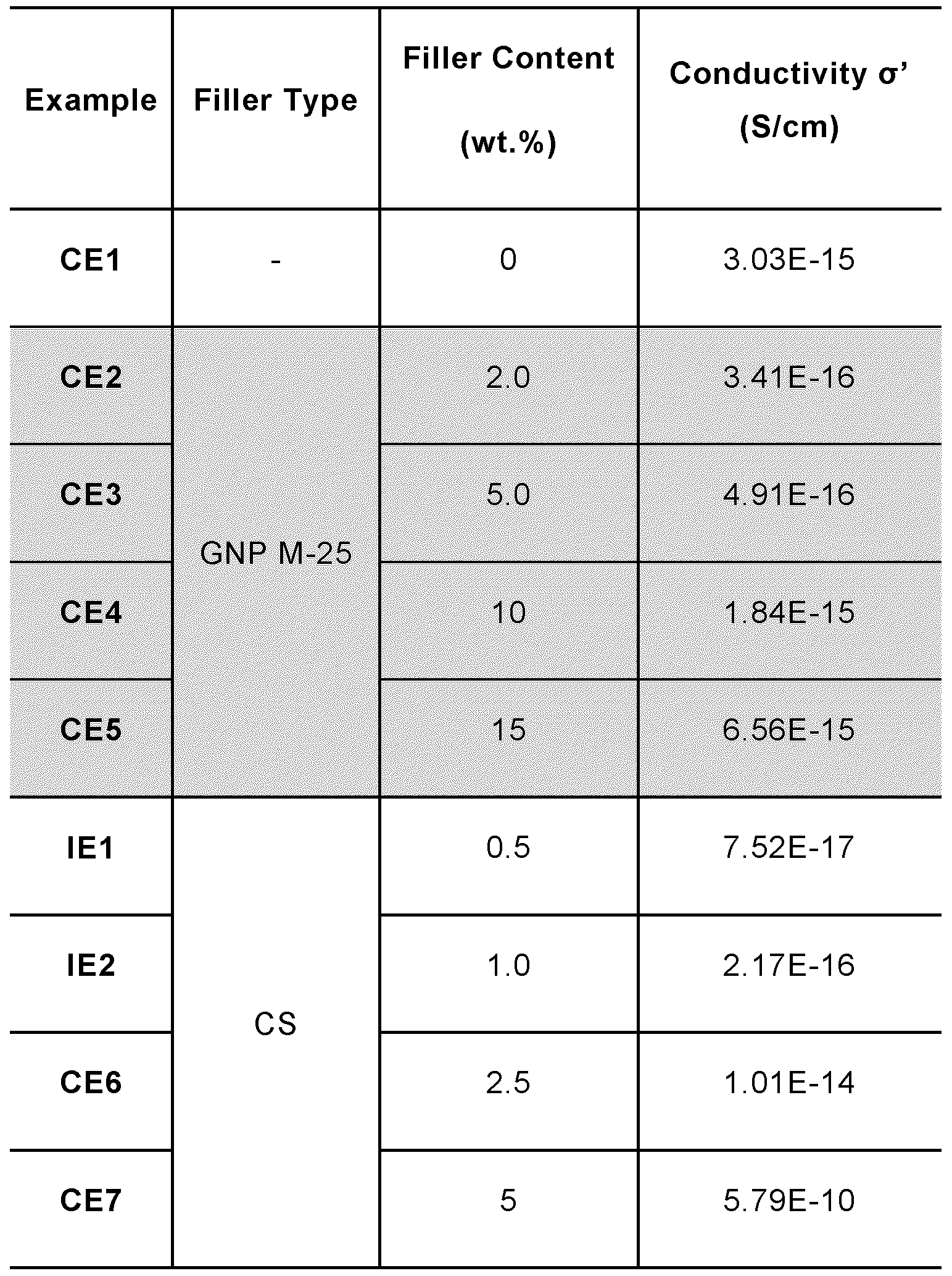
In Table 2 and Fig. 3, the conductivity data of comparative examples CE1 to CE7 and inventive examples IE1 and IE2 plotted against the filler content can be
seen. In Figure 1 “LLDPE07/GNP” denotes examples CE2 to CE5 with GNP as filler, whereas “LLDPE07/CS” denotes examples I E 1 , IE2, CE6 and CE7 comprising CS as filler. From these results it can be seen that despite the addition of almost 15 wt.% of graphene (GNP M-25) the overall conductivity of the composition exhibits invariant behaviour and remains within an order of magnitude with respect to the pure polymer base resin (CE1 ). For both CS-based examples IE1 and IE2 a significant drop in electrical conductivity of almost 1.5- orders of magnitude at low filler concentrations is observed, making the inventive examples comparable with the current FIVDC grades. Although the present invention has been described with reference to various embodiments, those skilled in the art will recognize that changes may be made without departing from the scope of the invention. It is intended that the detailed description be regarded as illustrative, and that the appended claims including all the equivalents are intended to define the scope of the invention.
Claims
1. An insulating polyolefin composition comprising
(a) an olefin polymer base resin having a first electrical conductivity, and (b) carbonaceous structures being reduced graphite oxide worm-like
(rGOW) structures in an amount of less than 2 wt.% based on the total weight of the insulating polyolefin composition, wherein the insulating polyolefin composition has a second electrical conductivity, and wherein said second electrical conductivity of said insulating polyolefin composition is lower than said first electrical conductivity of said olefin polymer base resin (a).
2. The insulating polyolefin composition according to claim 1 , wherein the carbonaceous structures (b) have a BET surface area of at least 200 m2/g.
3. The insulating polyolefin composition according to claim 1 or 2, wherein the carbonaceous structures (b) have a density less than 100 g/L.
4. The insulating polyolefin composition according to claim 1 or 2, wherein the carbonaceous structures (b) have a density of between 15 and 100 g/L.
5. The insulating polyolefin composition according to claim 1 or 2, wherein the carbonaceous structures (b) have a density of between 5 and 15 g/L.
6. The insulating polyolefin composition according any one of the preceding claims, wherein the carbonaceous structures (b) have a volatile content of less than 30%.
7. The insulating polyolefin composition according to any one of the preceding claims, wherein the length L of the carbonaceous structures (b) is at least 1 pm.
8. The insulating polyolefin composition according to any one of the preceding claims, wherein the diameter d of the carbonaceous structures (b) is from 50 nm to 200 pm.
9. The insulating polyolefin composition according to any one of the preceding claims, wherein the carbonaceous structures (b) have an aspect ratio of length L to diameter d that is 1 : 1 or more.
10. The insulating polyolefin composition according to any one of the preceding claims, wherein the added amount of said carbonaceous structures is in the range of from 0.1 to 2 wt.%, preferably 0.2 to 1 wt.%, more preferably 0.3 to 0.8 wt.%, based on the total weight of the polyolefin composition.
1 1 . The insulating polyolefin composition according to any one of the preceding claims, wherein the olefin polymer base resin (a) is selected from the group consisting of a C2 to Cs olefin homo- or copolymer.
12. The insulating polyolefin composition according to any one of the preceding claims, wherein the olefin polymer base resin (a) is an ethylene homo- or copolymer.
13. The insulating polyolefin composition according to any one of the preceding claims, wherein the olefin polymer base resin (a) is an ethylene-a-olefin having a density in the range of 860 to 900 kg/m3 and an MFR2 (190°C/2.16kg) measured according to ISO 1 133 in the range of 0.5 to 50.0 g/10min
14. A power cable comprising an insulating layer which comprises the insulating polyolefin composition as defined in any one of the preceding claim s.
15. Use of the insulating polyolefin composition as defined in any one of the preceding claims 1 to 13 in an insulating layer of a power cable.
Applications Claiming Priority (2)
| Application Number | Priority Date | Filing Date | Title |
|---|---|---|---|
| EP19154780.1 | 2019-01-31 | ||
| EP19154780 | 2019-01-31 |
Publications (1)
| Publication Number | Publication Date |
|---|---|
| WO2020157258A1 true WO2020157258A1 (en) | 2020-08-06 |
Family
ID=65276006
Family Applications (1)
| Application Number | Title | Priority Date | Filing Date |
|---|---|---|---|
| PCT/EP2020/052392 Ceased WO2020157258A1 (en) | 2019-01-31 | 2020-01-31 | Insulating polyolefin composition comprising carbonaceous structures with reduced electrical conductivity |
Country Status (1)
| Country | Link |
|---|---|
| WO (1) | WO2020157258A1 (en) |
Citations (13)
| Publication number | Priority date | Publication date | Assignee | Title |
|---|---|---|---|---|
| US20020054995A1 (en) | 1999-10-06 | 2002-05-09 | Marian Mazurkiewicz | Graphite platelet nanostructures |
| WO2003002652A1 (en) | 2001-06-29 | 2003-01-09 | Ciba Specialty Chemicals Holding Inc. | Additive functionalized organophilic nano-scaled fillers |
| US20040127621A1 (en) | 2002-09-12 | 2004-07-01 | Board Of Trustees Of Michigan State University | Expanded graphite and products produced therefrom |
| US20060231792A1 (en) | 2002-09-12 | 2006-10-19 | Board Of Trustees Of Michigan State University | Expanded graphite and products produced therefrom |
| US20060241237A1 (en) | 2002-09-12 | 2006-10-26 | Board Of Trustees Of Michigan State University | Continuous process for producing exfoliated nano-graphite platelets |
| WO2013033603A1 (en) | 2011-09-01 | 2013-03-07 | Rensselaer Polytechnic Institute | Graphene oxide polymer with nonlinear resistivity |
| EP2374842B1 (en) | 2010-04-06 | 2013-07-10 | Borealis AG | Semiconductive polyolefin composition comprising conductive filler |
| EP2711933A1 (en) * | 2012-09-19 | 2014-03-26 | LS Cable & System Ltd. | Insulation composition for DC power cable and DC power cable prepared by using the same |
| WO2019070514A1 (en) | 2017-10-02 | 2019-04-11 | Cabot Corporation | Methods and apparatus for the production of graphite oxide and reduced graphene oxide |
| EP3495411A1 (en) * | 2017-12-11 | 2019-06-12 | Borealis AG | Semiconductive polyolefin composition comprising carbonaceous structures, method for preparing the semiconductive polyolefin composition and use thereof |
| EP3495412A1 (en) * | 2017-12-11 | 2019-06-12 | Borealis AG | Semiconductive polyolefin composition comprising carbonaceous structures, method for preparing the semiconductive polyolefin composition and use thereof |
| EP3495410A1 (en) * | 2017-12-11 | 2019-06-12 | Borealis AG | Polypropylene composition comprising carbonaceous structures and having improved mechanical properties |
| WO2019115544A1 (en) * | 2017-12-11 | 2019-06-20 | Borealis Ag | Polypropylene composition comprising reduced graphite oxide worm-like structures and having improved mechanical properties |
-
2020
- 2020-01-31 WO PCT/EP2020/052392 patent/WO2020157258A1/en not_active Ceased
Patent Citations (14)
| Publication number | Priority date | Publication date | Assignee | Title |
|---|---|---|---|---|
| US20020054995A1 (en) | 1999-10-06 | 2002-05-09 | Marian Mazurkiewicz | Graphite platelet nanostructures |
| WO2003002652A1 (en) | 2001-06-29 | 2003-01-09 | Ciba Specialty Chemicals Holding Inc. | Additive functionalized organophilic nano-scaled fillers |
| WO2003024602A1 (en) | 2001-09-14 | 2003-03-27 | Cornerstone Technologies, L.L.C. | Graphite platelet nanostructures |
| US20040127621A1 (en) | 2002-09-12 | 2004-07-01 | Board Of Trustees Of Michigan State University | Expanded graphite and products produced therefrom |
| US20060231792A1 (en) | 2002-09-12 | 2006-10-19 | Board Of Trustees Of Michigan State University | Expanded graphite and products produced therefrom |
| US20060241237A1 (en) | 2002-09-12 | 2006-10-26 | Board Of Trustees Of Michigan State University | Continuous process for producing exfoliated nano-graphite platelets |
| EP2374842B1 (en) | 2010-04-06 | 2013-07-10 | Borealis AG | Semiconductive polyolefin composition comprising conductive filler |
| WO2013033603A1 (en) | 2011-09-01 | 2013-03-07 | Rensselaer Polytechnic Institute | Graphene oxide polymer with nonlinear resistivity |
| EP2711933A1 (en) * | 2012-09-19 | 2014-03-26 | LS Cable & System Ltd. | Insulation composition for DC power cable and DC power cable prepared by using the same |
| WO2019070514A1 (en) | 2017-10-02 | 2019-04-11 | Cabot Corporation | Methods and apparatus for the production of graphite oxide and reduced graphene oxide |
| EP3495411A1 (en) * | 2017-12-11 | 2019-06-12 | Borealis AG | Semiconductive polyolefin composition comprising carbonaceous structures, method for preparing the semiconductive polyolefin composition and use thereof |
| EP3495412A1 (en) * | 2017-12-11 | 2019-06-12 | Borealis AG | Semiconductive polyolefin composition comprising carbonaceous structures, method for preparing the semiconductive polyolefin composition and use thereof |
| EP3495410A1 (en) * | 2017-12-11 | 2019-06-12 | Borealis AG | Polypropylene composition comprising carbonaceous structures and having improved mechanical properties |
| WO2019115544A1 (en) * | 2017-12-11 | 2019-06-20 | Borealis Ag | Polypropylene composition comprising reduced graphite oxide worm-like structures and having improved mechanical properties |
Non-Patent Citations (6)
| Title |
|---|
| "Encyclopedia of Polymer Science and Engineering", vol. 6, 1986, pages: 383 - 410 |
| LEI DONG ET AL: "Synthesis and reduction of large sized graphene oxide sheets", CHEMICAL SOCIETY REVIEWS, vol. 46, no. 23, 1 January 2017 (2017-01-01), UK, pages 7306 - 7316, XP055609633, ISSN: 0306-0012, DOI: 10.1039/C7CS00485K * |
| R. NARESH KUMAR ET AL: "Reducing agent free synthesis of graphene from graphene oxide", AIP CONFERENCE PROCEEDINGS, 1 January 2013 (2013-01-01), NEW YORK, US, pages 262 - 265, XP055609641, ISSN: 0094-243X, DOI: 10.1063/1.4810070 * |
| R.KLIMESCHD.LITTMANNF.-O. MAHLING: "Encyclopedia of Materials: Science and Technology", 2001, ELSEVIER SCIENCE LTD., article "Polyethylene: High-pressure", pages: 7181 - 7184 |
| SCHNIEPP, JOURNAL OF PHYSICAL CHEMISTRY B, vol. 110, 2006, pages 853 |
| STANKOVICH ET AL., NATURE, vol. 442, 2006, pages 282 |
Similar Documents
| Publication | Publication Date | Title |
|---|---|---|
| EP2374842B2 (en) | Semiconductive polyolefin composition comprising conductive filler | |
| EP3495411A1 (en) | Semiconductive polyolefin composition comprising carbonaceous structures, method for preparing the semiconductive polyolefin composition and use thereof | |
| Nachtigall et al. | Macromolecular coupling agents for flame retardant materials | |
| KR20190107058A (en) | Seed free particles with carbon allotrope | |
| EP3495410A1 (en) | Polypropylene composition comprising carbonaceous structures and having improved mechanical properties | |
| EP2671892A1 (en) | Method for producing flake graphite-polymer composite material | |
| EP3495412A1 (en) | Semiconductive polyolefin composition comprising carbonaceous structures, method for preparing the semiconductive polyolefin composition and use thereof | |
| EP2998273A1 (en) | Magnesium hydroxide fire retardant nanoparticles and production method thereof | |
| JPH06509905A (en) | Electrical device with polymeric insulating member and semiconductor member | |
| EP2806006B1 (en) | Thermal conduction enhancer | |
| KR102338016B1 (en) | Polymer Compositions and Electrical Devices | |
| KR101301541B1 (en) | A novel composite of graphene and non-polar polyolefins and a method for the preparation thereof | |
| EP3495409A1 (en) | Polypropylene composition comprising carbonaceous structures and having improved mechanical properties | |
| WO2007013678A2 (en) | Carbon black, method for producing the same, and its use | |
| WO2020157301A1 (en) | Polyolefin composition comprising carbonaceous structures with reduced dielectric loss | |
| Feng et al. | Boosting flame retardancy of thermoplastic polyurethane: Synergistic effect of nickel phosphide nanoparticles and molybdenum disulfide nanosheets | |
| WO2020157285A1 (en) | Polyethylene composition comprising carbonaceous structures and having improved mechanical properties | |
| EP4195223B1 (en) | Semiconductive polyolefin composition comprising carbonaceous structures, power cable comprising the same and use thereof | |
| WO2020157275A1 (en) | Polyolefin composition comprising carbonaceous structures with reduced dielectric loss | |
| WO2020157256A1 (en) | Polyolefin composition comprising carbonaceous structures having improved thermal conductivity | |
| WO2020157291A1 (en) | Polypropylene composition comprising carbonaceous structures and having improved mechanical properties | |
| WO2020157254A1 (en) | Polyolefin composition comprising graphene nanoplatelets with invariant electrical conductivity | |
| Yang | Preparation and flammability of PVC/CuAl-LDH nanocomposites synthesized by melt blending | |
| Yasin et al. | Immobilisation of copper (I) oxide/zinc oxide nanoparticles on the gas diffusion layer for Co2 reduction reaction application | |
| Zhang et al. | Preparation of ethylene-propylene-rubber/graphene nanocomposites via an in situ polymerization method with supported metallocene catalyst |
Legal Events
| Date | Code | Title | Description |
|---|---|---|---|
| 121 | Ep: the epo has been informed by wipo that ep was designated in this application |
Ref document number: 20702296 Country of ref document: EP Kind code of ref document: A1 |
|
| NENP | Non-entry into the national phase |
Ref country code: DE |
|
| 122 | Ep: pct application non-entry in european phase |
Ref document number: 20702296 Country of ref document: EP Kind code of ref document: A1 |