WO2020156958A1 - A hermetic compressor with a counterweight - Google Patents
A hermetic compressor with a counterweight Download PDFInfo
- Publication number
- WO2020156958A1 WO2020156958A1 PCT/EP2020/051809 EP2020051809W WO2020156958A1 WO 2020156958 A1 WO2020156958 A1 WO 2020156958A1 EP 2020051809 W EP2020051809 W EP 2020051809W WO 2020156958 A1 WO2020156958 A1 WO 2020156958A1
- Authority
- WO
- WIPO (PCT)
- Prior art keywords
- rotor
- counterweight
- hermetic compressor
- wall
- biasing means
- Prior art date
- Legal status (The legal status is an assumption and is not a legal conclusion. Google has not performed a legal analysis and makes no representation as to the accuracy of the status listed.)
- Ceased
Links
Images


Classifications
-
- F—MECHANICAL ENGINEERING; LIGHTING; HEATING; WEAPONS; BLASTING
- F04—POSITIVE - DISPLACEMENT MACHINES FOR LIQUIDS; PUMPS FOR LIQUIDS OR ELASTIC FLUIDS
- F04C—ROTARY-PISTON, OR OSCILLATING-PISTON, POSITIVE-DISPLACEMENT MACHINES FOR LIQUIDS; ROTARY-PISTON, OR OSCILLATING-PISTON, POSITIVE-DISPLACEMENT PUMPS
- F04C23/00—Combinations of two or more pumps, each being of rotary-piston or oscillating-piston type, specially adapted for elastic fluids; Pumping installations specially adapted for elastic fluids; Multi-stage pumps specially adapted for elastic fluids
- F04C23/008—Hermetic pumps
-
- F—MECHANICAL ENGINEERING; LIGHTING; HEATING; WEAPONS; BLASTING
- F04—POSITIVE - DISPLACEMENT MACHINES FOR LIQUIDS; PUMPS FOR LIQUIDS OR ELASTIC FLUIDS
- F04C—ROTARY-PISTON, OR OSCILLATING-PISTON, POSITIVE-DISPLACEMENT MACHINES FOR LIQUIDS; ROTARY-PISTON, OR OSCILLATING-PISTON, POSITIVE-DISPLACEMENT PUMPS
- F04C18/00—Rotary-piston pumps specially adapted for elastic fluids
- F04C18/02—Rotary-piston pumps specially adapted for elastic fluids of arcuate-engagement type, i.e. with circular translatory movement of co-operating members, each member having the same number of teeth or tooth-equivalents
- F04C18/0207—Rotary-piston pumps specially adapted for elastic fluids of arcuate-engagement type, i.e. with circular translatory movement of co-operating members, each member having the same number of teeth or tooth-equivalents both members having co-operating elements in spiral form
- F04C18/0215—Rotary-piston pumps specially adapted for elastic fluids of arcuate-engagement type, i.e. with circular translatory movement of co-operating members, each member having the same number of teeth or tooth-equivalents both members having co-operating elements in spiral form where only one member is moving
-
- F—MECHANICAL ENGINEERING; LIGHTING; HEATING; WEAPONS; BLASTING
- F04—POSITIVE - DISPLACEMENT MACHINES FOR LIQUIDS; PUMPS FOR LIQUIDS OR ELASTIC FLUIDS
- F04C—ROTARY-PISTON, OR OSCILLATING-PISTON, POSITIVE-DISPLACEMENT MACHINES FOR LIQUIDS; ROTARY-PISTON, OR OSCILLATING-PISTON, POSITIVE-DISPLACEMENT PUMPS
- F04C29/00—Component parts, details or accessories of pumps or pumping installations, not provided for in groups F04C18/00 - F04C28/00
- F04C29/0021—Systems for the equilibration of forces acting on the pump
-
- F—MECHANICAL ENGINEERING; LIGHTING; HEATING; WEAPONS; BLASTING
- F04—POSITIVE - DISPLACEMENT MACHINES FOR LIQUIDS; PUMPS FOR LIQUIDS OR ELASTIC FLUIDS
- F04C—ROTARY-PISTON, OR OSCILLATING-PISTON, POSITIVE-DISPLACEMENT MACHINES FOR LIQUIDS; ROTARY-PISTON, OR OSCILLATING-PISTON, POSITIVE-DISPLACEMENT PUMPS
- F04C2230/00—Manufacture
- F04C2230/60—Assembly methods
-
- F—MECHANICAL ENGINEERING; LIGHTING; HEATING; WEAPONS; BLASTING
- F04—POSITIVE - DISPLACEMENT MACHINES FOR LIQUIDS; PUMPS FOR LIQUIDS OR ELASTIC FLUIDS
- F04C—ROTARY-PISTON, OR OSCILLATING-PISTON, POSITIVE-DISPLACEMENT MACHINES FOR LIQUIDS; ROTARY-PISTON, OR OSCILLATING-PISTON, POSITIVE-DISPLACEMENT PUMPS
- F04C2240/00—Components
- F04C2240/80—Other components
- F04C2240/807—Balance weight, counterweight
Definitions
- the present invention relates to a hermetic compressor, in particular to a hermetic compressor having a counterweight.
- a cooling appliance typically utilizes a hermetic compressor to cyclically convey the refrigerant from an evaporator to a condenser.
- the hermetic compressor is formed by a housing, hermetically isolating the operational parts such as the rotor and the stator of the hermetic compressor from the outer environment.
- the rotor and a shaft passing through the rotor rotates.
- relatively high centrifugal forces are generated which, in turn, act on the rotor especially when the refrigerant is being compressed.
- the hermetic compressor is configured to rotate the rotor and the shaft according to the cooling needs of the cooling appliance meaning that the higher cooling needs require the higher number of revolutions per minute.
- the rotation causes the rotor and the shaft to vibrate which, in turn, increases the energy consumption of the hermetic compressor.
- Another problem is the noise level caused by the vibrations of the rotor and the shaft. Therefore, it is vital to minimize the vibrations so as to decrease the energy consumption and the noise level of the hermetic compressor.
- An objective of the present invention is to eliminate the vibrations and the noise resulting during the operation of the hermetic compressor in an economic and easily reproducible manner.
- the hermetic compressor of the present invention comprises a housing, hermetically separating the interior volume of the hermetic compressor from the outer environment.
- the housing houses a rotor and a stator wherein the stator is placed around the rotor so as to be concentric with the rotor.
- the concentricity of the rotor and the stator lies along a rotation axis.
- the rotor is in the shape of a cylinder having two flat surfaces.
- a rotor cover is placed on to each of the flat surfaces of the rotor. Each rotor cover comprises a recess.
- the recess has a first wall and a second wall wherein the first wall is closer to the rotational axis.
- a counterweight is placed inside the recess in a sliding manner. Once the hermetic compressor is energized, the rotor starts to rotate around the rotation axis and as a result the counterweight starts to slide toward the second wall.
- the biasing means is placed to be in between the counterweight and one of the said side walls and configured to bias the counterweight toward the first wall. As the revolution per minute of the rotor increases, the centrifugal force increases, forcing the counterweight toward the second wall.
- the biasing means is configured to bias the position of the counterweight toward the first wall.
- the exact position of the counterweight can be adjusted inside the recess by use of the biasing means which, in turn, helps the vibrations caused by the rotation of the rotor and the shaft to be damped. This helps reduce friction between the rotor, the shaft and the stator therefore reducing energy consumption of the hermetic compressor.
- Another advantageous effect of damping the vibration is that the overall noise level of the hermetic compressor and that of the cooling appliance is reduced.
- the recess is formed on to each of the rotor cover wherein the rotor covers are placed on to the flat surfaces of the rotor.
- the position of the recesses on the respective rotor covers is configured to be symmetrical with respect to the rotation axis.
- each of the rotor cover has one recess and the position of the recesses are diagonal with respect to the rotation axis.
- the biasing means extends in between the counterweight and the first wall.
- the hermetic compressor is at rest and the rotor remains inactive and the counterweight is in initial position.
- the biasing means applies a restoring force to the counterweight, retracting the counterweight toward the initial position. Attaching the biasing means in between the first wall and the counterweight helps to bias the counterweight toward the initial condition in an easy and reproducible way, meanwhile decreasing the noise level and the energy consumption of the hermetic compressor.
- the biasing means is a helical spring.
- the helical springs are easy and cheap to produce and the spring constant of the biasing means remains almost constant as the revolution per minute of the rotor increases.
- the restoring force of the biasing means increases linearly with the change of distance in between the counterweight and the first wall making the helical springs highly suitable for damping the vibrations of the hermetic compressor.
- the biasing means extends in between the counterweight and the second wall. As the rotor starts to rotate, the counterweight slides toward the second wall. The biasing means is compressed between the counterweight and the second wall. The biasing means applies a restoring force to the counterweight, pushing the counterweight toward the first wall. Therefore, the position of the counterweight is adjusted according to the revolution per minute of the rotor, which helps to damp the vibration and reduce the noise caused by the vibration.
- the biasing means is a leaf spring.
- the leaf spring is placed in between the counterweight and the second wall. Upon rotation of the rotor, the spring is compressed, therefore creating a restoring force opposing against the centrifugal force formed as a result of the rotation of the rotor.
- plurality of biasing means are placed in between the counterweight and the first wall and the second wall.
- plurality of biasing means which are helical springs are placed in between the counterweight and the first wall and the second wall improving damping of the vibrations.
- the biasing means which is a leaf spring
- the biasing means which is a helical spring is placed in between the counterweight and the second wall and the first wall respectively. It is possible to use any combination of the biasing means thereof.
- Use of the plurality of the biasing means is especially advantageous to damp the vibrations of the hermetic compressor at high revolution per minute. The high revolution per minute being higher than 2000 revolution per minute.
- the vibrations caused by a wide range of revolution per minute values can be eliminated via the use of the counterweight and the biasing means placed inside the recess. By this means, the noise level and the energy consumption of the hermetic compressor is improved.
- Figure 1 – is a cross sectional side view of the hermetic compressor
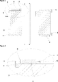
- Figure 2 – is a cross-sectional side view of the rotor and the rotor cover
- Figure 3 – is an enlarged view of dashed A-A lines in Figure 2
- Figure 4 – is an exploded view of the rotor and the rotor cover
- Figure 5 — is an upper view of the rotor cover
- the present invention relates to a hermetic compressor (1) comprising; a housing (2), a rotor (3) and a stator (4) inside the housing (2) and wherein the stator (4) is placed around the rotor (3) so as to be concentric with the rotor (3) around a rotation axis (I), a rotor cover (5) placed onto a planar surface of the rotor (3), a recess (6) on the rotor cover (5) having a first wall (7) and a second wall (8) wherein the first wall is closer to the rotation axis (I) and a counterweight (9) placed inside the recess (6).
- the present invention relates to a hermetic compressor (1) comprising; a biasing means (10) inside the recess (6) biasing the counterweight (9) into a predetermined position and wherein the counterweight (9) is configured to slidably move inside the recess (6) upon rotation of the rotor (3).
- the hermetic compressor (1) comprises various rotating parts, such as the stator (4) which is placed co-centric and around the rotor (3).
- the central axis of the rotor (3) and the stator (4) is a cylindrical shaped channel through which a shaft passes through. As the hermetic compressor (1) is energized, the rotor (3) starts to rotate around and inside the stator (4).
- the shaft rotates and as the shaft rotates, the oil stored at the bottom of the housing (2) climbs up the shaft and oils the moving parts. As a result, the parts are prevented from wearing out.
- the rotor (3) is cylindrically shaped and the ends of the rotor (3) is covered by the pair of the rotor covers (5).
- the rotor (3) rotates around the rotation axis (I) and this rotation axis (I) lies along the central axis of the stator (4).
- the shaft is also configured to rotate around the rotation axis (I).
- the recess (6) is formed on to the rotor cover (5) and comprises the first wall (7) and the second wall (8) wherein the first wall (7) is closer to the rotation axis (I).
- the counterweight (9) is placed inside the recess (6) and is free to move in a slidable manner between the first wall (7) and the second wall (8). As the hermetic compressor (1) is energized and the rotor (3) starts to rotate, the counterweight (9) is forced to slide toward the second wall (8) due to centrifugal force.
- the biasing means (10) is placed inside the recess (6) and is configured to be in between the counterweight (9) and one of the said walls (7,8). The biasing means (10) biases the counterweight (9) to the counterweight’s (9) initial position, the initial position being the position during which the hermetic compressor (1) is not energized and thus the rotor (3) does not rotate.
- the centrifugal force forces the counterweight (9) to slide toward the second wall (8) and the biasing means (10) forms a restoring force to the movement of the counterweight (9).
- the revolution per minute of the hermetic compressor (1) varies according to the cooling needs of the cooling appliance wherein the hermetic compressor (1) is utilized. As the revolution per minute of the rotor (3) increases, the centrifugal force applied to the counterweight (9) increases and as a result, the restoring force acting against the counterweight (9) applied by the biasing means (10) increases. By this means, the exact location of the counterweight (9) depending on various revolution per minute values can be adjusted, damping the vibrations caused by the rotation of the rotor (3).
- the damping effect of the biasing means helps to keep noise level of the hermetic compressor (1) at a minimum level.
- the vibrations also cause the hermetic compressor (1) to use more energy.
- use of the biasing means (10) minimizes the noise level and the energy consumption of the hermetic compressor (1).
- the recess (6) is formed onto each one of the rotor covers (5) and wherein the recesses (6) are configured to be symmetrical with respect to the rotation axis (I).
- the pair of rotor covers (5) cover the rotor (3) from both ends.
- the recesses (6) are formed on both of the rotor covers (5) into which the counterweights (9) are placed.
- the location of the recesses (6) is configured to be symmetrical with respect to the rotation axis (I) meaning that their location is diagonal.
- the biasing means (10) extends in between the first wall (7) and the counterweight (9).
- the biasing means (10) is placed so as to extend in between the first wall (7) and the counterweight (9). Therefore, as the rotor (3) starts to rotate, the centrifugal force forces the counterweight (9) to move toward the second wall (8) whereas the biasing means (10) biases the counterweight (9) toward the first wall (7).
- the revolution per minute of the rotor (3) increases the restoring force exerted by the biasing means (10) to the counterweight (9) increases. As a result, the vibrations caused by the rotation of the rotor (3) is minimized, decreasing the noise level and the energy consumption of the hermetic compressor (1).
- the biasing means (10) is a helical spring.
- the biasing means (10) is in the form of a helical spring and extends in between the first wall (7) and the counterweight (9).
- the biasing means (10) extends in between the second wall (8) and the counterweight (9).
- the biasing means (10) is placed so as to extend in between the second wall (8) and the counterweight (9). Therefore, as the rotor (3) starts to rotate, the centrifugal force forces the counterweight (9) to move toward the second wall (8) whereas the biasing means (10) biases the counterweight (9) away from and toward the second wall (8) and the first wall (7) respectively.
- the biasing means (10) applies more restoring force. As a result, the vibrations caused by the rotation of the rotor (3) is minimized, decreasing the noise level and the energy consumption of the hermetic compressor (1).
- the biasing means (10) is a leaf spring.
- the biasing means (10) is in the form of a leaf spring and extends in between the second wall (8) and the counterweight (9).
- the leaf springs in the shape of a “V” are cheap and easy to produce and also to assemble in between the counterweight (9) and the second wall (8).
- the revolution per minute of the rotor (3) increases the centrifugal force affecting the counterweight (9) increases.
- the restoring force applied by the biasing means (10) to the counterweight (9) increases proportional to the centrifugal force applied on to the counterweight (9).
- the hermetic compressor (1) comprises an arc shaped recess (6), and a corresponding arch shaped counterweight (9), the straight edges of the said arcs being perpendicular to the rotation axis (I) of the rotor (3).
- the imaginary lines extending along the edges of the arcs intersect the rotation axis (I) with 90 degree.
- the counterweight (9) and the biasing means (10) work with the centrifugal force principal. Because of that, the effect of the counterweight (9) is proportional to the position of the counterweight’s (9) center of gravity. In order to fully utilize the weight of the counterweight (9), it is essential to use the recess (6) with concave geometries such as arc shapes therefore increasing the performance of the counterweight (9).
- the vibrations are dampened by use the counterweight (9) and the biasing means (10) inside the recess (6) formed on to the rotor cover (5), minimizing the noise level and the energy consumption of the hermetic compressor (1).
Landscapes
- Engineering & Computer Science (AREA)
- Mechanical Engineering (AREA)
- General Engineering & Computer Science (AREA)
- Compressor (AREA)
- Applications Or Details Of Rotary Compressors (AREA)
- Structures Of Non-Positive Displacement Pumps (AREA)
Abstract
The present invention relates to a hermetic compressor (1) comprising; a housing (2), a rotor (3) and a stator (4) inside the housing (2) and wherein the stator (4) is placed around the rotor (3) so as to be concentric with the rotor (3) around a rotation axis (I), a rotor cover (5) placed onto a planar surface of the rotor (3), a recess (6) on the rotor cover (5) having a first wall (7) and a second wall (8) wherein the first wall (7) is closer to the rotation axis (I) and a counterweight (9) placed inside the recess (6).
Description
The present invention relates to a hermetic compressor, in particular to a hermetic compressor having a counterweight.
A cooling appliance typically utilizes a hermetic compressor to cyclically convey the refrigerant from an evaporator to a condenser. The hermetic compressor is formed by a housing, hermetically isolating the operational parts such as the rotor and the stator of the hermetic compressor from the outer environment. During the operation of the hermetic compressor, the rotor and a shaft passing through the rotor rotates. During the rotation of the rotor and the shaft, relatively high centrifugal forces are generated which, in turn, act on the rotor especially when the refrigerant is being compressed. The hermetic compressor is configured to rotate the rotor and the shaft according to the cooling needs of the cooling appliance meaning that the higher cooling needs require the higher number of revolutions per minute. The rotation causes the rotor and the shaft to vibrate which, in turn, increases the energy consumption of the hermetic compressor. Another problem is the noise level caused by the vibrations of the rotor and the shaft. Therefore, it is vital to minimize the vibrations so as to decrease the energy consumption and the noise level of the hermetic compressor.
A prior art publication in the technical field of the present invention may be referred to as US5476369A among others, the document disclosing a compressor having a lower axial ring placed onto the rotor wherein the lower axial ring comprises a counterweight.
An objective of the present invention is to eliminate the vibrations and the noise resulting during the operation of the hermetic compressor in an economic and easily reproducible manner.
The objective has been achieved by the counterweight according to the present invention as defined in the independent claim 1. Further achievements have been attained by the subject matters respectively defined in the dependent claims.
The hermetic compressor of the present invention comprises a housing, hermetically separating the interior volume of the hermetic compressor from the outer environment. The housing houses a rotor and a stator wherein the stator is placed around the rotor so as to be concentric with the rotor. The concentricity of the rotor and the stator lies along a rotation axis. As the hermetic compressor is energized, the rotor, along with a shaft passing through the rotor, starts to rotate around the rotation axis. The rotor is in the shape of a cylinder having two flat surfaces. A rotor cover is placed on to each of the flat surfaces of the rotor. Each rotor cover comprises a recess. The recess has a first wall and a second wall wherein the first wall is closer to the rotational axis. A counterweight is placed inside the recess in a sliding manner. Once the hermetic compressor is energized, the rotor starts to rotate around the rotation axis and as a result the counterweight starts to slide toward the second wall. The biasing means is placed to be in between the counterweight and one of the said side walls and configured to bias the counterweight toward the first wall. As the revolution per minute of the rotor increases, the centrifugal force increases, forcing the counterweight toward the second wall. The biasing means is configured to bias the position of the counterweight toward the first wall. As a result, the exact position of the counterweight can be adjusted inside the recess by use of the biasing means which, in turn, helps the vibrations caused by the rotation of the rotor and the shaft to be damped. This helps reduce friction between the rotor, the shaft and the stator therefore reducing energy consumption of the hermetic compressor. Another advantageous effect of damping the vibration is that the overall noise level of the hermetic compressor and that of the cooling appliance is reduced.
In another embodiment of the invention, the recess is formed on to each of the rotor cover wherein the rotor covers are placed on to the flat surfaces of the rotor. The position of the recesses on the respective rotor covers is configured to be symmetrical with respect to the rotation axis. In other words, each of the rotor cover has one recess and the position of the recesses are diagonal with respect to the rotation axis. This embodiment helps to further increase the damping effect of the counterweight and the biasing means which, in turn, helps reducing vibrations thereby reducing the noise level and the energy consumption of the hermetic compressor.
In another embodiment of the invention, the biasing means extends in between the counterweight and the first wall. During initial position the hermetic compressor is at rest and the rotor remains inactive and the counterweight is in initial position. As the rotor starts to rotate, the counterweight slides toward the second wall. The biasing means applies a restoring force to the counterweight, retracting the counterweight toward the initial position. Attaching the biasing means in between the first wall and the counterweight helps to bias the counterweight toward the initial condition in an easy and reproducible way, meanwhile decreasing the noise level and the energy consumption of the hermetic compressor.
In another embodiment of the invention, the biasing means is a helical spring. The helical springs are easy and cheap to produce and the spring constant of the biasing means remains almost constant as the revolution per minute of the rotor increases. The restoring force of the biasing means increases linearly with the change of distance in between the counterweight and the first wall making the helical springs highly suitable for damping the vibrations of the hermetic compressor.
In another embodiment of the invention, the biasing means extends in between the counterweight and the second wall. As the rotor starts to rotate, the counterweight slides toward the second wall. The biasing means is compressed between the counterweight and the second wall. The biasing means applies a restoring force to the counterweight, pushing the counterweight toward the first wall. Therefore, the position of the counterweight is adjusted according to the revolution per minute of the rotor, which helps to damp the vibration and reduce the noise caused by the vibration.
In another embodiment of the invention, the biasing means is a leaf spring. The leaf spring is placed in between the counterweight and the second wall. Upon rotation of the rotor, the spring is compressed, therefore creating a restoring force opposing against the centrifugal force formed as a result of the rotation of the rotor.
In another embodiment of the invention, plurality of biasing means are placed in between the counterweight and the first wall and the second wall. In one embodiment, plurality of biasing means which are helical springs are placed in between the counterweight and the first wall and the second wall improving damping of the vibrations. In another embodiment, the biasing means, which is a leaf spring, and the biasing means, which is a helical spring is placed in between the counterweight and the second wall and the first wall respectively. It is possible to use any combination of the biasing means thereof. Use of the plurality of the biasing means is especially advantageous to damp the vibrations of the hermetic compressor at high revolution per minute. The high revolution per minute being higher than 2000 revolution per minute.
In the hermetic compressor of the present invention, the vibrations caused by a wide range of revolution per minute values can be eliminated via the use of the counterweight and the biasing means placed inside the recess. By this means, the noise level and the energy consumption of the hermetic compressor is improved.
The drawings are not meant to delimit the scope of protection as identified in the claims nor should they be referred to alone in an effort to interpret the scope identified in the claims without recourse to the technical disclosure in the description of the present invention.
Figure 1 – is a cross sectional side view of the hermetic compressor
Figure 2 – is a cross-sectional side view of the rotor and the rotor cover
Figure 3 – is an enlarged view of dashed A-A lines in Figure 2
Figure 4 – is an exploded view of the rotor and the rotor cover
Figure 5 – is an upper view of the rotor cover
The following numerals are assigned to different parts demonstrated in the drawings and referred to in the present detailed description of the invention:
- Hermetic Compressor
- Housing
- Rotor
- Stator
- Rotor cover
- Recess
- First wall
- Second wall
- Counterweight
- Biasing means
The present invention relates to a hermetic compressor (1) comprising; a housing (2), a rotor (3) and a stator (4) inside the housing (2) and wherein the stator (4) is placed around the rotor (3) so as to be concentric with the rotor (3) around a rotation axis (I), a rotor cover (5) placed onto a planar surface of the rotor (3), a recess (6) on the rotor cover (5) having a first wall (7) and a second wall (8) wherein the first wall is closer to the rotation axis (I) and a counterweight (9) placed inside the recess (6).
The present invention relates to a hermetic compressor (1) comprising; a biasing means (10) inside the recess (6) biasing the counterweight (9) into a predetermined position and wherein the counterweight (9) is configured to slidably move inside the recess (6) upon rotation of the rotor (3). The hermetic compressor (1) comprises various rotating parts, such as the stator (4) which is placed co-centric and around the rotor (3). The central axis of the rotor (3) and the stator (4) is a cylindrical shaped channel through which a shaft passes through. As the hermetic compressor (1) is energized, the rotor (3) starts to rotate around and inside the stator (4). Similarly the shaft rotates and as the shaft rotates, the oil stored at the bottom of the housing (2) climbs up the shaft and oils the moving parts. As a result, the parts are prevented from wearing out. The rotor (3) is cylindrically shaped and the ends of the rotor (3) is covered by the pair of the rotor covers (5). The rotor (3), rotates around the rotation axis (I) and this rotation axis (I) lies along the central axis of the stator (4). The shaft is also configured to rotate around the rotation axis (I). The recess (6) is formed on to the rotor cover (5) and comprises the first wall (7) and the second wall (8) wherein the first wall (7) is closer to the rotation axis (I). The counterweight (9) is placed inside the recess (6) and is free to move in a slidable manner between the first wall (7) and the second wall (8). As the hermetic compressor (1) is energized and the rotor (3) starts to rotate, the counterweight (9) is forced to slide toward the second wall (8) due to centrifugal force. The biasing means (10) is placed inside the recess (6) and is configured to be in between the counterweight (9) and one of the said walls (7,8). The biasing means (10) biases the counterweight (9) to the counterweight’s (9) initial position, the initial position being the position during which the hermetic compressor (1) is not energized and thus the rotor (3) does not rotate. As the rotor (3) starts to rotate, the centrifugal force forces the counterweight (9) to slide toward the second wall (8) and the biasing means (10) forms a restoring force to the movement of the counterweight (9). The revolution per minute of the hermetic compressor (1) varies according to the cooling needs of the cooling appliance wherein the hermetic compressor (1) is utilized. As the revolution per minute of the rotor (3) increases, the centrifugal force applied to the counterweight (9) increases and as a result, the restoring force acting against the counterweight (9) applied by the biasing means (10) increases. By this means, the exact location of the counterweight (9) depending on various revolution per minute values can be adjusted, damping the vibrations caused by the rotation of the rotor (3). The damping effect of the biasing means helps to keep noise level of the hermetic compressor (1) at a minimum level. The vibrations also cause the hermetic compressor (1) to use more energy. As a result, use of the biasing means (10) minimizes the noise level and the energy consumption of the hermetic compressor (1). (Figure – 1)
In another embodiment of the hermetic compressor (1), the recess (6) is formed onto each one of the rotor covers (5) and wherein the recesses (6) are configured to be symmetrical with respect to the rotation axis (I). The pair of rotor covers (5) cover the rotor (3) from both ends. The recesses (6) are formed on both of the rotor covers (5) into which the counterweights (9) are placed. The location of the recesses (6) is configured to be symmetrical with respect to the rotation axis (I) meaning that their location is diagonal. By use of the recesses on both of the rotor covers (5) further minimizes the noise level and the energy consumption of the hermetic compressor (1). (Figure – 2)
In another embodiment of the hermetic compressor (1), the biasing means (10) extends in between the first wall (7) and the counterweight (9). The biasing means (10) is placed so as to extend in between the first wall (7) and the counterweight (9). Therefore, as the rotor (3) starts to rotate, the centrifugal force forces the counterweight (9) to move toward the second wall (8) whereas the biasing means (10) biases the counterweight (9) toward the first wall (7). As the revolution per minute of the rotor (3) increases the restoring force exerted by the biasing means (10) to the counterweight (9) increases. As a result, the vibrations caused by the rotation of the rotor (3) is minimized, decreasing the noise level and the energy consumption of the hermetic compressor (1).
In another embodiment of the hermetic compressor (1), the biasing means (10) is a helical spring. The biasing means (10) is in the form of a helical spring and extends in between the first wall (7) and the counterweight (9). An advantage of using a helical springs as the biasing means (10) is that they are cheap and easy to produce. As the revolution per minute of the rotor (3) increases the centrifugal force affecting the counterweight (9) increases. As a result the restoring force exerted by the biasing means (10) to the counterweight (9) increases proportional to the centrifugal force applied on to the counterweight (9). (Figure – 3 and 4)
In another embodiment of the hermetic compressor (1), the biasing means (10) extends in between the second wall (8) and the counterweight (9). The biasing means (10) is placed so as to extend in between the second wall (8) and the counterweight (9). Therefore, as the rotor (3) starts to rotate, the centrifugal force forces the counterweight (9) to move toward the second wall (8) whereas the biasing means (10) biases the counterweight (9) away from and toward the second wall (8) and the first wall (7) respectively. As the revolution per minute of the rotor (3) increases the biasing means (10) applies more restoring force. As a result, the vibrations caused by the rotation of the rotor (3) is minimized, decreasing the noise level and the energy consumption of the hermetic compressor (1).
In another embodiment of the hermetic compressor (1), the biasing means (10) is a leaf spring. The biasing means (10) is in the form of a leaf spring and extends in between the second wall (8) and the counterweight (9). The leaf springs in the shape of a “V” are cheap and easy to produce and also to assemble in between the counterweight (9) and the second wall (8). As the revolution per minute of the rotor (3) increases the centrifugal force affecting the counterweight (9) increases. As a result the restoring force applied by the biasing means (10) to the counterweight (9) increases proportional to the centrifugal force applied on to the counterweight (9). (Figure – 5)
In another embodiment, the hermetic compressor (1) comprises an arc shaped recess (6), and a corresponding arch shaped counterweight (9), the straight edges of the said arcs being perpendicular to the rotation axis (I) of the rotor (3). The imaginary lines extending along the edges of the arcs intersect the rotation axis (I) with 90 degree. The counterweight (9) and the biasing means (10) work with the centrifugal force principal. Because of that, the effect of the counterweight (9) is proportional to the position of the counterweight’s (9) center of gravity. In order to fully utilize the weight of the counterweight (9), it is essential to use the recess (6) with concave geometries such as arc shapes therefore increasing the performance of the counterweight (9).
In the hermetic compressor (1) of the present invention, the vibrations are dampened by use the counterweight (9) and the biasing means (10) inside the recess (6) formed on to the rotor cover (5), minimizing the noise level and the energy consumption of the hermetic compressor (1).
Claims (7)
- A hermetic compressor (1) comprising;a housing (2), a rotor (3) and a stator (4) inside the housing (2) and wherein the stator (4) is placed around the rotor (3) so as to be concentric with the rotor (3) around a rotation axis (I),a rotor cover (5) placed onto a planar surface of the rotor (3),a recess (6) on the rotor cover (5) having a first wall (7) and a second wall (8) wherein the first wall (7) is closer to the rotation axis (I),a counterweight (9) placed inside the recess (6),characterized bya biasing means (10) inside the recess (6) biasing the counterweight (9) into a predetermined position and wherein the counterweight (9) is configured to slidably move inside the recess (6) upon rotation of the rotor (3).
- A hermetic compressor (1) according to claim 1, characterized in that the recess (6) is formed onto each one of the rotor covers (5) and wherein the recesses (6) are configured to be symmetrical with respect to the rotation axis (I).
- A hermetic compressor (1) according to any one of the preceding claims, characterized in that the biasing means (10) extends in between the first wall (7) and the counterweight (9).
- A hermetic compressor (1) according to any one of the preceding claims, characterized in that the biasing means (10) is a helical spring.
- A hermetic compressor (1) according to claim 1 and 2, characterized in that the biasing means (10) extends in between the second wall (8) and the counterweight (9).
- A hermetic compressor (1) according to claim 5, characterized in that the biasing means (10) is a leaf spring.
- A hermetic compressor (1) according to any one of the preceding claims, characterized by an arc shaped recess (6), and by a corresponding arch shaped counterweight (9), the straight edges of the said arcs being perpendicular to the rotation axis (I) of the rotor (3).
Applications Claiming Priority (2)
| Application Number | Priority Date | Filing Date | Title |
|---|---|---|---|
| TR201901406 | 2019-01-30 | ||
| TR2019/01406 | 2019-01-30 |
Publications (1)
| Publication Number | Publication Date |
|---|---|
| WO2020156958A1 true WO2020156958A1 (en) | 2020-08-06 |
Family
ID=69232855
Family Applications (1)
| Application Number | Title | Priority Date | Filing Date |
|---|---|---|---|
| PCT/EP2020/051809 Ceased WO2020156958A1 (en) | 2019-01-30 | 2020-01-24 | A hermetic compressor with a counterweight |
Country Status (1)
| Country | Link |
|---|---|
| WO (1) | WO2020156958A1 (en) |
Citations (5)
| Publication number | Priority date | Publication date | Assignee | Title |
|---|---|---|---|---|
| JPS6213789A (en) * | 1985-07-12 | 1987-01-22 | Hitachi Ltd | scroll compressor |
| US5460494A (en) * | 1993-06-08 | 1995-10-24 | Samsung Electronics Co., Ltd. | Orbiting scroll actuating means of a scroll-type compressor |
| US5476369A (en) | 1994-07-25 | 1995-12-19 | Tecumseh Products Company | Rotor counterweight insert apparatus |
| KR200391204Y1 (en) * | 2005-05-19 | 2005-07-29 | 엘지전자 주식회사 | Scroll compressor having movable balance weight |
| CN106337812A (en) * | 2016-10-21 | 2017-01-18 | 珠海格力节能环保制冷技术研究中心有限公司 | Balance block and rotor assembly, shaft assembly and compressor with balance block |
-
2020
- 2020-01-24 WO PCT/EP2020/051809 patent/WO2020156958A1/en not_active Ceased
Patent Citations (5)
| Publication number | Priority date | Publication date | Assignee | Title |
|---|---|---|---|---|
| JPS6213789A (en) * | 1985-07-12 | 1987-01-22 | Hitachi Ltd | scroll compressor |
| US5460494A (en) * | 1993-06-08 | 1995-10-24 | Samsung Electronics Co., Ltd. | Orbiting scroll actuating means of a scroll-type compressor |
| US5476369A (en) | 1994-07-25 | 1995-12-19 | Tecumseh Products Company | Rotor counterweight insert apparatus |
| KR200391204Y1 (en) * | 2005-05-19 | 2005-07-29 | 엘지전자 주식회사 | Scroll compressor having movable balance weight |
| CN106337812A (en) * | 2016-10-21 | 2017-01-18 | 珠海格力节能环保制冷技术研究中心有限公司 | Balance block and rotor assembly, shaft assembly and compressor with balance block |
Similar Documents
| Publication | Publication Date | Title |
|---|---|---|
| EP2789856B1 (en) | Scroll compressor | |
| CN104246287B (en) | Rotational vibration damping components | |
| CN102893054B (en) | Dynamic damper | |
| EP0422311A1 (en) | Arrangement for reducing bearing loads in scroll compressors | |
| JP7573552B2 (en) | ROTOR SUPPORT AND VACUUM PUMP EQUIPPED WITH SUCH A ROTOR SUPPORT - Patent application | |
| CN107949701B (en) | compressor | |
| JP6711386B2 (en) | Housing device for blower motor and vehicle air conditioner | |
| US5059102A (en) | Fluid scroll machine with peripherally attached counter weights and reduced thickness scroll | |
| WO2002008636A2 (en) | An automatic balancer for balancing a mass rotating about an axis | |
| CN102918752B (en) | Vibration damping for an electric device | |
| CN109185151A (en) | Vibration reduction balance block, compressor and refrigeration equipment | |
| JP2003083395A (en) | Rotating machinery | |
| CN110846854A (en) | Vibration damping device, washing machine | |
| JP4302636B2 (en) | Torsional damping rotating shaft | |
| JP2003013995A (en) | Power transmission mechanism and compressor | |
| US20080007127A1 (en) | Shock prevention structure for motor | |
| US6433462B2 (en) | Ultrasonic motor and method for manufacturing the same | |
| KR20230006019A (en) | Compressor with damping scroll | |
| CN209385554U (en) | Housing, rotor bearing and electric motor | |
| KR20010112894A (en) | Hermetic Compressor | |
| JP5522061B2 (en) | Dynamic damper | |
| KR20020062187A (en) | Enclosed compressor | |
| JP2010144517A (en) | Hermetic compressor | |
| CN115875266A (en) | Balance weight of scroll compressor and scroll compressor including the same | |
| JP6686994B2 (en) | Scroll compressor |
Legal Events
| Date | Code | Title | Description |
|---|---|---|---|
| 121 | Ep: the epo has been informed by wipo that ep was designated in this application |
Ref document number: 20702111 Country of ref document: EP Kind code of ref document: A1 |
|
| NENP | Non-entry into the national phase |
Ref country code: DE |
|
| 122 | Ep: pct application non-entry in european phase |
Ref document number: 20702111 Country of ref document: EP Kind code of ref document: A1 |