WO2020150535A1 - Methods and apparatus of linear model derivation for video coding - Google Patents
Methods and apparatus of linear model derivation for video coding Download PDFInfo
- Publication number
- WO2020150535A1 WO2020150535A1 PCT/US2020/013965 US2020013965W WO2020150535A1 WO 2020150535 A1 WO2020150535 A1 WO 2020150535A1 US 2020013965 W US2020013965 W US 2020013965W WO 2020150535 A1 WO2020150535 A1 WO 2020150535A1
- Authority
- WO
- WIPO (PCT)
- Prior art keywords
- sample
- neighboring samples
- samples
- parameters
- referred
- Prior art date
- Legal status (The legal status is an assumption and is not a legal conclusion. Google has not performed a legal analysis and makes no representation as to the accuracy of the status listed.)
- Ceased
Links
Classifications
-
- H—ELECTRICITY
- H04—ELECTRIC COMMUNICATION TECHNIQUE
- H04N—PICTORIAL COMMUNICATION, e.g. TELEVISION
- H04N19/00—Methods or arrangements for coding, decoding, compressing or decompressing digital video signals
- H04N19/10—Methods or arrangements for coding, decoding, compressing or decompressing digital video signals using adaptive coding
- H04N19/102—Methods or arrangements for coding, decoding, compressing or decompressing digital video signals using adaptive coding characterised by the element, parameter or selection affected or controlled by the adaptive coding
- H04N19/103—Selection of coding mode or of prediction mode
- H04N19/105—Selection of the reference unit for prediction within a chosen coding or prediction mode, e.g. adaptive choice of position and number of pixels used for prediction
-
- H—ELECTRICITY
- H04—ELECTRIC COMMUNICATION TECHNIQUE
- H04N—PICTORIAL COMMUNICATION, e.g. TELEVISION
- H04N19/00—Methods or arrangements for coding, decoding, compressing or decompressing digital video signals
- H04N19/10—Methods or arrangements for coding, decoding, compressing or decompressing digital video signals using adaptive coding
- H04N19/102—Methods or arrangements for coding, decoding, compressing or decompressing digital video signals using adaptive coding characterised by the element, parameter or selection affected or controlled by the adaptive coding
- H04N19/117—Filters, e.g. for pre-processing or post-processing
-
- H—ELECTRICITY
- H04—ELECTRIC COMMUNICATION TECHNIQUE
- H04N—PICTORIAL COMMUNICATION, e.g. TELEVISION
- H04N19/00—Methods or arrangements for coding, decoding, compressing or decompressing digital video signals
- H04N19/10—Methods or arrangements for coding, decoding, compressing or decompressing digital video signals using adaptive coding
- H04N19/134—Methods or arrangements for coding, decoding, compressing or decompressing digital video signals using adaptive coding characterised by the element, parameter or criterion affecting or controlling the adaptive coding
- H04N19/157—Assigned coding mode, i.e. the coding mode being predefined or preselected to be further used for selection of another element or parameter
- H04N19/159—Prediction type, e.g. intra-frame, inter-frame or bidirectional frame prediction
-
- H—ELECTRICITY
- H04—ELECTRIC COMMUNICATION TECHNIQUE
- H04N—PICTORIAL COMMUNICATION, e.g. TELEVISION
- H04N19/00—Methods or arrangements for coding, decoding, compressing or decompressing digital video signals
- H04N19/10—Methods or arrangements for coding, decoding, compressing or decompressing digital video signals using adaptive coding
- H04N19/134—Methods or arrangements for coding, decoding, compressing or decompressing digital video signals using adaptive coding characterised by the element, parameter or criterion affecting or controlling the adaptive coding
- H04N19/167—Position within a video image, e.g. region of interest [ROI]
-
- H—ELECTRICITY
- H04—ELECTRIC COMMUNICATION TECHNIQUE
- H04N—PICTORIAL COMMUNICATION, e.g. TELEVISION
- H04N19/00—Methods or arrangements for coding, decoding, compressing or decompressing digital video signals
- H04N19/10—Methods or arrangements for coding, decoding, compressing or decompressing digital video signals using adaptive coding
- H04N19/169—Methods or arrangements for coding, decoding, compressing or decompressing digital video signals using adaptive coding characterised by the coding unit, i.e. the structural portion or semantic portion of the video signal being the object or the subject of the adaptive coding
- H04N19/17—Methods or arrangements for coding, decoding, compressing or decompressing digital video signals using adaptive coding characterised by the coding unit, i.e. the structural portion or semantic portion of the video signal being the object or the subject of the adaptive coding the unit being an image region, e.g. an object
- H04N19/176—Methods or arrangements for coding, decoding, compressing or decompressing digital video signals using adaptive coding characterised by the coding unit, i.e. the structural portion or semantic portion of the video signal being the object or the subject of the adaptive coding the unit being an image region, e.g. an object the region being a block, e.g. a macroblock
-
- H—ELECTRICITY
- H04—ELECTRIC COMMUNICATION TECHNIQUE
- H04N—PICTORIAL COMMUNICATION, e.g. TELEVISION
- H04N19/00—Methods or arrangements for coding, decoding, compressing or decompressing digital video signals
- H04N19/10—Methods or arrangements for coding, decoding, compressing or decompressing digital video signals using adaptive coding
- H04N19/169—Methods or arrangements for coding, decoding, compressing or decompressing digital video signals using adaptive coding characterised by the coding unit, i.e. the structural portion or semantic portion of the video signal being the object or the subject of the adaptive coding
- H04N19/186—Methods or arrangements for coding, decoding, compressing or decompressing digital video signals using adaptive coding characterised by the coding unit, i.e. the structural portion or semantic portion of the video signal being the object or the subject of the adaptive coding the unit being a colour or a chrominance component
Definitions
- the present application generally relates to video coding and compression, and in particular but not limited to, methods and apparatus for generating a prediction signal using a linear model in video coding.
- Digital video is supported by a variety of electronic devices, such as digital televisions, laptop or desktop computers, tablet computers, digital cameras, digital recording devices, digital media players, video gaming consoles, smart phones, video teleconferencing devices, video streaming devices, etc.
- the electronic devices transmit, receive, encode, decode, and/or store digital video data by implementing video compression/decompression.
- Digital video devices implement video coding techniques, such as those described in the standards defined by Versatile Video Coding (VVC), Joint Exploration Test Model (JEM), MPEG-2, MPEG-4, ITU-T H.263, ITU-T H.264/MPEG-4, Part 10, Advanced Video Coding (AVC), ITU-T H.265/High Efficiency Video Coding (HEVC), and extensions of such standards.
- VVC Versatile Video Coding
- JEM Joint Exploration Test Model
- MPEG-2 Joint Exploration Test Model
- MPEG-4 Joint Exploration Test Model
- ITU-T H.263, ITU-T H.264/MPEG-4 Part 10, Advanced Video Cod
- Video coding generally utilizes prediction methods (e.g., inter-prediction, intra- prediction) that take advantage of redundancy present in video images or sequences.
- prediction methods e.g., inter-prediction, intra- prediction
- An important goal of video coding techniques is to compress video data into a form that uses a lower bit rate, while avoiding or minimizing degradations to video quality. With ever-evolving video services becoming available, encoding techniques with better coding efficiency are needed.
- Video compression typically includes performing spatial (intra frame) prediction and/or temporal (inter frame) prediction to reduce or remove redundancy inherent in the video data.
- a video frame is partitioned into one or more slices, each slice having multiple video blocks, which may also be referred to as coding tree units (CTUs).
- Each CTU may contain one coding unit (CU) or recursively split into smaller CUs until the predefined minimum CU size is reached.
- Each CU also named leaf CU
- TUs transform units
- PUs prediction units
- Each CU can be coded in intra, inter or IBC modes.
- Video blocks in an intra coded (I) slice of a video frame are encoded using spatial prediction with respect to reference samples in neighbor blocks within the same video frame.
- Video blocks in an inter coded (P or B) slice of a video frame may use spatial prediction with respect to reference samples in neighbor blocks within the same video frame or temporal prediction with respect to reference samples in other previous and/or future reference video frames.
- the process of finding the reference block may be accomplished by block matching algorithm.
- Residual data representing pixel differences between the current block to be coded and the predictive block is referred to as a residual block or prediction errors.
- An inter-coded block is encoded according to a motion vector that points to a reference block in a reference frame forming the predictive block, and the residual block. The process of determining the motion vector is typically referred to as motion estimation.
- An intra coded block is encoded according to an intra prediction mode and the residual block.
- the residual block is transformed from the pixel domain to a transform domain, e.g., frequency domain, resulting in residual transform coefficients, which may then be quantized.
- the quantized transform coefficients initially arranged in a two-dimensional array, may be scanned to produce a one-dimensional vector of transform coefficients, and then entropy encoded into a video bitstream to achieve even more compression.
- the encoded video bitstream is then saved in a computer-readable storage medium (e.g., flash memory) to be accessed by another electronic device with digital video capability or directly transmitted to the electronic device wired or wirelessly.
- the electronic device then performs video decompression (which is an opposite process to the video compression described above) by, e.g., parsing the encoded video bitstream to obtain syntax elements from the bitstream and reconstructing the digital video data to its original format from the encoded video bitstream based at least in part on the syntax elements obtained from the bitstream, and renders the reconstructed digital video data on a display of the electronic device.
- video decompression which is an opposite process to the video compression described above
- JVET Joint Video Experts Team
- VVC Versatile Video Coding
- VTM1 VVC Test Model 1
- this disclosure describes examples of techniques relating to generation of prediction signals using linear models in video coding.
- a method for video coding including: deriving prediction parameters a and b, using neighboring reconstructed chroma samples and their referred samples, by a parameter deriving process; and determining whether Local Illumination Compensation (LIC) mode is applied to a current Coding Unit (CU), and upon determining that the LIC mode is applied, deriving parameters a2 and b2 for the LIC by execution of the parameter deriving process, and obtaining a final LIC predictor based on equation: where a2 and b2 are instances of the parameters a and b; pred ⁇ (i, j) represents LIC predicted samples in the current CU; and rec'' ⁇ (i, j) represents reference samples in a reference picture of the current CU.
- LIC Local Illumination Compensation
- an apparatus for video coding including: a processor; and a memory configured to store instructions executable by the processor; where the processor, upon execution of the instructions, is configured to: derive prediction parameters a and b, using neighboring reconstructed chroma samples and their referred samples, by a parameter deriving process; and determine whether Local Illumination Compensation (LIC) mode is applied to a current Coding Unit (CU), and upon determining that the LIC mode is applied, derive parameters a2 and b2 for the LIC by execution of the parameter deriving process, and obtain a final LIC predictor based on equation: where a2 and b2 are instances of the parameters a and b; p red ⁇ (i, j) represents LIC predicted samples in the current CU; and rec'' ⁇ (i, j) represents reference samples in a reference picture of the current CU.
- LIC Local Illumination Compensation
- a non-transitory computer readable storage medium including instructions stored therein, where, upon execution of the instructions by a processor, the instructions cause the processor to: derive prediction parameters a and b, using neighboring reconstructed chroma samples and their referred samples, by a parameter deriving process; and determine whether Local Illumination Compensation (LIC) mode is applied to a current Coding Unit (CU), and upon determining that the LIC mode is applied, derive parameters a2 and b2 for the LIC by execution of the parameter deriving process, and obtain a final LIC predictor based on equation:
- LIC Local Illumination Compensation
- pred ⁇ (i, j) represents LIC predicted samples in the current CU; and represents reference
- FIG. 1 is a block diagram illustrating an exemplary video encoding and decoding system in accordance with some implementations of the present disclosure.
- FIG. 2 is a block diagram illustrating an exemplary video encoder in accordance with some implementations of the present disclosure.
- FIG. 3 is a block diagram illustrating an exemplary video decoder in accordance with some implementations of the present disclosure.
- FIG. 4 is a schematic diagram illustrating luma and chroma pixel sampling grids for yuv 4:2:0 format in accordance with some implementations of the present disclosure.
- FIG. 5 is a schematic diagram illustrating locations of samples used for derivation of parameters a1 and b1 in a cross-component linear model (CCLM) prediction mode in accordance with some implementations of the present disclosure.
- CCLM cross-component linear model
- FIG. 6 is a schematic diagram illustrating straight line derivation of a1 and b1 using a min-Max method in accordance with some implementations of the present disclosure.
- FIG.7 is a schematic diagram illustrating LM_A mode for derivation of a1 and b1 in accordance with some implementations of the present disclosure.
- FIG.8 is a schematic diagram illustrating LM_L mode for derivation of a1 and b1 in accordance with some implementations of the present disclosure.
- FIG. 9 is a schematic diagram illustrating luma and chroma pixel sampling grids for yuv 4:2:2 format in accordance with some implementations of the present disclosure.
- FIG. 10 is a schematic diagram illustrating luma and chroma pixel sampling grids for yuv 4:4:4 format in accordance with some implementations of the present disclosure.
- FIG.11 is a schematic diagram illustrating neighboring samples used for derivation of parameters a2 and b2 in a local illumination compensation (LIC) mode in accordance with some implementations of the present disclosure.
- LIC local illumination compensation
- FIG. 12 is a schematic diagram illustrating an example of sample selection for derivation of CCLM/LIC parameters in accordance with some implementations of the present disclosure.
- FIG. 13 is a schematic diagram illustrating an example of sample selection for derivation of CCLM/LIC parameters in accordance with some implementations of the present disclosure.
- FIG. 14 is a schematic diagram illustrating an example of sample selection for derivation of CCLM/LIC parameters in accordance with some implementations of the present disclosure.
- FIG. 15 is a schematic diagram illustrating an example of sample selection for derivation of CCLM/LIC parameters in accordance with some implementations of the present disclosure.
- FIG. 16 is a schematic diagram illustrating an example of sample selection for derivation of CCLM/LIC parameters in accordance with some implementations of the present disclosure.
- FIG. 17 is a schematic diagram illustrating an example of sample selection for derivation of CCLM/LIC parameters in accordance with some implementations of the present disclosure.
- FIG. 18 is a schematic diagram illustrating an example of sample selection for derivation of CCLM/LIC parameters in accordance with some implementations of the present disclosure.
- FIG. 19 is a schematic diagram illustrating an example of sample selection for derivation of CCLM/LIC parameters in accordance with some implementations of the present disclosure.
- FIG. 20 is a block diagram illustrating an exemplary apparatus for video coding in accordance with some implementations of the present disclosure.
- FIG.21 is a flowchart illustrating an exemplary process of video coding for generating prediction signals using linear models in accordance with some implementations of the present disclosure.
- a“first,”“second,”“third,” and etc. are all used as nomenclature only for references to relevant elements, e.g. devices, components, compositions, steps, and etc., without implying any spatial or chronological orders, unless expressly specified otherwise.
- a“first device” and a“second device” may refer to two separately formed devices, or two parts, components or operational states of a same device, and may be named arbitrarily.
- module may include memory (shared, dedicated, or group) that stores code or instructions that can be executed by one or more processors.
- a module may include one or more circuits with or without stored code or instructions.
- the module or circuit may include one or more components that are directly or indirectly connected. These components may or may not be physically attached to, or located adjacent to, one another.
- a unit or module may be implemented purely by software, purely by hardware, or by a combination of hardware and software.
- the unit or module may include functionally related code blocks or software components, that are directly or indirectly linked together, so as to perform a particular function.
- FIG. 1 is a block diagram illustrating an exemplary system 10 for encoding and decoding video blocks in accordance with some implementations of the present disclosure.
- the system 10 includes a source device 12 that generates and encodes video data which is to be decoded at a later time by a destination device 14.
- the source device 12 and the destination device 14 may be any of a wide variety of electronic devices, including desktop or laptop computers, tablet computers, smart phones, set-top boxes, digital televisions, cameras, display devices, digital media players, video gaming consoles, video streaming device, or the like.
- the source device 12 and the destination device 14 are equipped with wireless communication capabilities.
- the destination device 14 may receive the encoded video data to be decoded via a link 16.
- the link 16 may be any type of communication medium or device capable of moving the encoded video data from the source device 12 to the destination device 14.
- the link 16 may be a communication medium to enable the source device 12 to transmit the encoded video data directly to the destination device 14 in real-time.
- the encoded video data may be modulated according to a communication standard, such as a wireless communication protocol, and transmitted to the destination device 14.
- the communication medium may be any wireless or wired communication medium, such as a radio frequency (RF) spectrum or one or more physical transmission lines.
- RF radio frequency
- the communication medium may form part of a packet-based network, such as a local area network, a wide-area network, or a global network such as the Internet.
- the communication medium may include routers, switches, base stations, or any other equipment that may be useful to facilitate communication from the source device 12 to the destination device 14.
- the encoded video data may be transmitted from an output interface 22 to a storage device 32. Subsequently, the encoded video data in the storage device 32 may be accessed by the destination device 14 via an input interface 28.
- the storage device 32 may include any of a variety of distributed or locally accessed data storage media such as a hard drive, Blu-ray discs, DVDs, CD-ROMs, flash memory, volatile or non-volatile memory, or any other suitable digital storage media for storing encoded video data.
- the storage device 32 may correspond to a file server or another intermediate storage device that may hold the encoded video data generated by the source device 12.
- the destination device 14 may access the stored video data from the storage device 32 via streaming or downloading.
- the file server may be any type of computer capable of storing encoded video data and transmitting the encoded video data to the destination device 14.
- Exemplary file servers include a web server (e.g., for a website), an FTP server, network attached storage (NAS) devices, or a local disk drive.
- the destination device 14 may access the encoded video data through any standard data connection, including a wireless channel (e.g., a Wi-Fi connection), a wired connection (e.g., DSL, cable modem, etc.), or a combination of both which is suitable for accessing encoded video data stored on a file server.
- the transmission of the encoded video data from the storage device 32 may be a streaming transmission, a download transmission, or a combination of both.
- the source device 12 includes a video source 18, a video encoder 20 and the output interface 22.
- the video source 18 may include a source such as a video capture device, e.g., a video camera, a video archive containing previously captured video, a video feed interface to receive video from a video content provider, and/or a computer graphics system for generating computer graphics data as the source video, or a combination of such sources.
- a video capture device e.g., a video camera, a video archive containing previously captured video, a video feed interface to receive video from a video content provider, and/or a computer graphics system for generating computer graphics data as the source video, or a combination of such sources.
- the source device 12 and the destination device 14 may be camera phones or video phones.
- the implementations described in the present disclosure may be applicable to video coding in general, and may be applied to wireless and/or wired applications.
- the captured, pre-captured, or computer-generated video may be encoded by the video encoder 20.
- the encoded video data may be transmitted directly to the destination device 14 via the output interface 22 of the source device 12.
- the encoded video data may also (or alternatively) be stored onto the storage device 32 for later access by the destination device 14 or other devices, for decoding and/or playback.
- the output interface 22 may further include a modem and/or a transmitter.
- the destination device 14 includes an input interface 28, a video decoder 30, and a display device 34.
- the input interface 28 may include a receiver and/or a modem and receive the encoded video data over the link 16.
- the encoded video data communicated over the link 16, or provided on the storage device 32 may include a variety of syntax elements generated by the video encoder 20 for use by the video decoder 30 in decoding the video data. Such syntax elements may be included within the encoded video data transmitted on a communication medium, stored on a storage medium, or stored a file server.
- the destination device 14 may include the display device 34, which may be an integrated display device or an external display device that is configured to communicate with the destination device 14.
- the display device 34 displays the decoded video data to a user, and may be any of a variety of display devices such as a liquid crystal display (LCD), a plasma display, an organic light emitting diode (OLED) display, or another type of display device.
- LCD liquid crystal display
- OLED organic light emitting diode
- the video encoder 20 and the video decoder 30 may operate according to proprietary or industry standards, such as VVC, HEVC, MPEG-4, Part 10, Advanced Video Coding (AVC), or extensions of such standards. It should be understood that the present disclosure is not limited to a specific video coding/decoding standard and may be applicable to other video coding/decoding standards. It is generally contemplated that the video encoder 20 of the source device 12 may be configured to encode video data according to any of these current or future standards. Similarly, it is also generally contemplated that the video decoder 30 of the destination device 14 may be configured to decode video data according to any of these current or future standards.
- the video encoder 20 and the video decoder 30 each may be implemented as any of a variety of suitable encoder circuitry, such as one or more microprocessors, digital signal processors (DSPs), application specific integrated circuits (ASICs), field programmable gate arrays (FPGAs), discrete logic, software, hardware, firmware or any combinations thereof.
- DSPs digital signal processors
- ASICs application specific integrated circuits
- FPGAs field programmable gate arrays
- an electronic device may store instructions for the software in a suitable, non-transitory computer-readable medium and execute the instructions in hardware using one or more processors to perform the video coding/decoding operations disclosed in the present disclosure.
- Each of the video encoder 20 and the video decoder 30 may be included in one or more encoders or decoders, either of which may be integrated as part of a combined encoder/decoder (CODEC) in a respective device.
- CDEC combined encoder/decoder
- FIG. 2 is a block diagram illustrating an exemplary video encoder 20 in accordance with some implementations described in the present disclosure.
- the video encoder 20 may perform intra and inter predictive coding of video blocks within video frames.
- Intra predictive coding relies on spatial prediction to reduce or remove spatial redundancy in video data within a given video frame or picture.
- Inter predictive coding relies on temporal prediction to reduce or remove temporal redundancy in video data within adjacent video frames or pictures of a video sequence.
- the video encoder 20 includes a video data memory 40, a prediction processing unit 41, a decoded picture buffer (DPB) 64, a summer 50, a transform processing unit 52, a quantization unit 54, and an entropy encoding unit 56.
- the prediction processing unit 41 further includes a motion estimation unit 42, a motion compensation unit 44, a partition unit 45, an intra prediction processing unit 46, an intra block copy (IBC) unit 48, and an intra/inter mode decision unit 49.
- the video encoder 20 also includes an inverse quantization unit 58, an inverse transform processing unit 60, and a summer 62 for video block reconstruction.
- a deblocking filter may be positioned between the summer 62 and the DPB 64 to filter block boundaries to remove blockiness artifacts from a reconstructed video.
- An in loop filter 63 may also be used in addition to the deblocking filter to filter the output of summer 62.
- the video encoder 20 may take the form of a fixed or programmable hardware unit or may be divided among one or more of the fixed or programmable hardware units.
- the video data memory 40 may store video data to be encoded by the components of the video encoder 20.
- the video data in the video data memory 40 may be obtained, for example, from the video source 18.
- the DPB 64 is a buffer that stores reference video data for use in encoding video data by the video encoder 20 (e.g., in intra or inter predictive coding modes).
- the video data memory 40 and DPB 64 may be any of a variety of memory devices.
- the video data memory 40 may be on-chip with other components of the video encoder 20, or off-chip relative to those components.
- the partition unit 45 within the prediction processing unit 41 partitions the video data into video blocks.
- This partitioning may also include partitioning a video frame into slices, tiles, or other larger coding units (CUs) according to a predefined splitting structures such as quad-tree structure associated with the video data.
- the video frame may be divided into multiple video blocks (or sets of video blocks referred to as tiles).
- the prediction processing unit 41 may select one of a plurality of possible predictive coding modes, such as one of a plurality of intra predictive coding modes or one of a plurality of inter predictive coding modes, for the current video block based on error results (e.g., coding rate and the level of distortion).
- the prediction processing unit 41 may provide the resulting intra or inter prediction coded block to the summer 50 to generate a residual block and to the summer 62 to reconstruct the encoded block for use as part of a reference frame subsequently.
- the prediction processing unit 41 also provides syntax elements, such as motion vectors, intra-mode indicators, partition information, and other such syntax information, to the entropy encoding unit 56.
- the intra prediction processing unit 46 within the prediction processing unit 41 may perform intra predictive coding of the current video block relative to one or more neighbor blocks in the same frame as the current block to be coded to provide spatial prediction.
- the motion estimation unit 42 and the motion compensation unit 44 within the prediction processing unit 41 perform inter predictive coding of the current video block relative to one or more predictive blocks in one or more reference frames to provide temporal prediction.
- the video encoder 20 may perform multiple coding passes, e.g., to select an appropriate coding mode for each block of the video data.
- the motion estimation unit 42 determines the inter prediction mode for a current video frame by generating a motion vector, which indicates the displacement of a prediction unit (PU) of a video block within the current video frame relative to a predictive block within a reference video frame, according to a predetermined pattern within a sequence of video frames.
- Motion estimation performed by the motion estimation unit 42, is the process of generating motion vectors, which estimate motion for video blocks.
- a motion vector may indicate the displacement of a PU of a video block within a current video frame or picture relative to a predictive block within a reference frame (or other coded unit) relative to the current block being coded within the current frame (or other coded unit).
- the predetermined pattern may designate video frames in the sequence as P frames or B frames.
- the intra BC unit 48 may determine vectors, e.g., block vectors, for intra BC coding in a manner similar to the determination of motion vectors by the motion estimation unit 42 for inter prediction, or may utilize the motion estimation unit 42 to determine the block vector.
- a predictive block is a block of a reference frame that is deemed as closely matching the PU of the video block to be coded in terms of pixel difference, which may be determined by sum of absolute difference (SAD), sum of square difference (SSD), or other difference metrics.
- the video encoder 20 may calculate values for sub-integer pixel positions of reference frames stored in the DPB 64. For example, the video encoder 20 may interpolate values of one-quarter pixel positions, one-eighth pixel positions, or other fractional pixel positions of the reference frame. Therefore, the motion estimation unit 42 may perform a motion search relative to the full pixel positions and fractional pixel positions, and output a motion vector with fractional pixel precision.
- the motion estimation unit 42 calculates a motion vector for a PU of a video block in an inter prediction coded frame by comparing the position of the PU to the position of a predictive block of a reference frame selected from a first reference frame list (e.g., List 0) or a second reference frame list (e.g., List 1), each of which identifies one or more reference frames stored in the DPB 64.
- the motion estimation unit 42 sends the calculated motion vector to the motion compensation unit 44 and then to the entropy encoding unit 56.
- Motion compensation performed by the motion compensation unit 44, may involve fetching or generating the predictive block based on the motion vector determined by the motion estimation unit 42.
- the motion compensation unit 44 may locate a predictive block to which the motion vector points in one of the reference frame lists, retrieve the predictive block from the DPB 64, and forward the predictive block to the summer 50.
- the summer 50 then forms a residual video block of pixel difference values by subtracting pixel values of the predictive block provided by the motion compensation unit 44 from the pixel values of the current video block being coded.
- the pixel difference values forming the residual vide block may include luma or chroma difference components or both.
- the motion compensation unit 44 may also generate syntax elements associated with the video blocks of a video frame for use by the video decoder 30 in decoding the video blocks of the video frame.
- the syntax elements may include, for example, syntax elements defining the motion vector used to identify the predictive block, any flags indicating the prediction mode, or any other syntax information described herein. Note that the motion estimation unit 42 and the motion compensation unit 44 may be highly integrated, but they are illustrated separately for conceptual purposes.
- the intra BC unit 48 may generate vectors and fetch predictive blocks in a manner similar to that described above in connection with the motion estimation unit 42 and the motion compensation unit 44, but with the predictive blocks being in the same frame as the current block being coded and with the vectors being referred to as block vectors as opposed to motion vectors.
- the intra BC unit 48 may determine an intra-prediction mode to use to encode a current block.
- the intra BC unit 48 may encode a current block using various intra-prediction modes, e.g., during separate encoding passes, and test their performance through rate-distortion analysis.
- the intra BC unit 48 may select, among the various tested intra-prediction modes, an appropriate intra- prediction mode to use and generate an intra-mode indicator accordingly. For example, the intra BC unit 48 may calculate rate-distortion values using a rate-distortion analysis for the various tested intra-prediction modes, and select the intra-prediction mode having the best rate- distortion characteristics among the tested modes as the appropriate intra-prediction mode to use. Rate-distortion analysis generally determines an amount of distortion (or error) between an encoded block and an original, unencoded block that was encoded to produce the encoded block, as well as a bitrate (i.e., a number of bits) used to produce the encoded block. The intra BC unit 48 may calculate ratios from the distortions and rates for the various encoded blocks to determine which intra-prediction mode exhibits the best rate-distortion value for the block.
- Rate-distortion analysis generally determines an amount of distortion (or error) between an encoded block and an original, unencoded block that was encoded
- the intra BC unit 48 may use the motion estimation unit 42 and the motion compensation unit 44, in whole or in part, to perform such functions for intra BC prediction according to the implementations described herein.
- a predictive block may be a block that is deemed as closely matching the block to be coded, in terms of pixel difference, which may be determined by sum of absolute difference (SAD), sum of squared difference (SSD), or other difference metrics, and identification of the predictive block may include calculation of values for sub-integer pixel positions.
- the video encoder 20 may form a residual video block by subtracting pixel values of the predictive block from the pixel values of the current video block being coded, forming pixel difference values.
- the pixel difference values forming the residual video block may include both luma and chroma component differences.
- the intra prediction processing unit 46 may intra-predict a current video block, as an alternative to the inter-prediction performed by the motion estimation unit 42 and the motion compensation unit 44, or the intra block copy prediction performed by the intra BC unit 48, as described above.
- the intra prediction processing unit 46 may determine an intra prediction mode to use to encode a current block. To do so, the intra prediction processing unit 46 may encode a current block using various intra prediction modes, e.g., during separate encoding passes, and the intra prediction processing unit 46 (or a mode select unit, in some examples) may select an appropriate intra prediction mode to use from the tested intra prediction modes.
- the intra prediction processing unit 46 may provide information indicative of the selected intra-prediction mode for the block to the entropy encoding unit 56.
- the entropy encoding unit 56 may encode the information indicating the selected intra-prediction mode in the bitstream.
- the summer 50 forms a residual video block by subtracting the predictive block from the current video block.
- the residual video data in the residual block may be included in one or more transform units (TUs) and is provided to the transform processing unit 52.
- the transform processing unit 52 transforms the residual video data into residual transform coefficients using a transform, such as a discrete cosine transform (DCT) or a conceptually similar transform.
- DCT discrete cosine transform
- the transform processing unit 52 may send the resulting transform coefficients to the quantization unit 54.
- the quantization unit 54 quantizes the transform coefficients to further reduce bit rate.
- the quantization process may also reduce the bit depth associated with some or all of the coefficients.
- the degree of quantization may be modified by adjusting a quantization parameter.
- the quantization unit 54 may then perform a scan of a matrix including the quantized transform coefficients.
- the entropy encoding unit 56 may perform the scan.
- the entropy encoding unit 56 entropy encodes the quantized transform coefficients into a video bitstream using, e.g., context adaptive variable length coding (CAVLC), context adaptive binary arithmetic coding (CABAC), syntax-based context- adaptive binary arithmetic coding (SBAC), probability interval partitioning entropy (PIPE) coding or another entropy encoding methodology or technique.
- CAVLC context adaptive variable length coding
- CABAC context adaptive binary arithmetic coding
- SBAC syntax-based context- adaptive binary arithmetic coding
- PIPE probability interval partitioning entropy
- the encoded bitstream may then be transmitted to the video decoder 30, or archived in the storage device 32 for later transmission to or retrieval by the video decoder 30.
- the entropy encoding unit 56 may also entropy encode the motion vectors and the other syntax elements for the current video frame being coded.
- the inverse quantization unit 58 and the inverse transform processing unit 60 apply inverse quantization and inverse transformation, respectively, to reconstruct the residual video block in the pixel domain for generating a reference block for prediction of other video blocks.
- the motion compensation unit 44 may generate a motion compensated predictive block from one or more reference blocks of the frames stored in the DPB 64.
- the motion compensation unit 44 may also apply one or more interpolation filters to the predictive block to calculate sub-integer pixel values for use in motion estimation.
- the summer 62 adds the reconstructed residual block to the motion compensated predictive block produced by the motion compensation unit 44 to produce a reference block for storage in the DPB 64.
- the reference block may then be used by the intra BC unit 48, the motion estimation unit 42 and the motion compensation unit 44 as a predictive block to inter predict another video block in a subsequent video frame.
- a video frame is partitioned into blocks for processing. For each given video block, a prediction is formed based on either inter prediction or intra prediction.
- inter prediction predictors or predictive blocks may be formed through motion estimation and motion compensation, based on pixels from previously reconstructed frames.
- intra prediction predictors may be formed based on reconstructed pixels in the current frame. Through mode decision, a best predictor may be chosen to predict a current block.
- the prediction residual or the residual block (i.e. the difference between a current block and its predictor) is sent to a transform module, for example, the transform processing unit 52.
- Transform coefficients are then sent to a quantization module, e.g., the quantization unit 54, for entropy reduction.
- Quantized coefficients are fed to an entropy coding module, e.g., the entropy encoding unit 56, to generate compressed video bitstream.
- a transform module for example, the transform processing unit 52.
- Transform coefficients are then sent to a quantization module, e.g., the quantization unit 54, for entropy reduction.
- Quantized coefficients are fed to an entropy coding module, e.g., the entropy encoding unit 56, to generate compressed video bitstream.
- prediction related information from inter and/or intra prediction modules is also going through an entropy coding module, e.g., the entropy encoding unit 56, and then saved into the bitstream.
- an entropy coding module e.g., the entropy encoding unit 56
- decoder related modules may be needed in order to reconstruct pixels for prediction purpose.
- the prediction residual is reconstructed through inverse quantization and inverse transform.
- the reconstructed prediction residual is then combined with the predictor to generate unfiltered reconstructed pixels for a current block.
- an in-loop filter 63 is commonly used.
- a deblocking filter is available in AVC, HEVC as well as VVC.
- SAO sample adaptive offset
- SAO sample adaptive offset
- ALF adaptive loop filter
- intra prediction is usually based on unfiltered reconstructed pixels, while inter prediction is based on filtered reconstructed pixels if these filters are turned on by the encoder.
- FIG. 3 is a block diagram illustrating an exemplary video decoder 30 in accordance with some implementations of the present disclosure.
- the video decoder 30 includes a video data memory 79, an entropy decoding unit 80, a prediction processing unit 81, an inverse quantization unit 86, an inverse transform processing unit 88, a summer 90, and a DPB 92.
- the prediction processing unit 81 further includes a motion compensation unit 82, an intra prediction processing unit 84, an intra BC unit 85, and an intra/inter mode selection unit 87.
- the video decoder 30 may perform a decoding process generally reciprocal to the encoding process described above with respect to the video encoder 20 in connection with FIG. 2.
- the motion compensation unit 82 may generate prediction data based on motion vectors received from the entropy decoding unit 80, while the intra-prediction unit 84 may generate prediction data based on intra-prediction mode indicators received from the entropy decoding unit 80.
- the bitstream received is decoded through the entropy decoding unit 80 to derive quantized coefficient levels (or quantized coefficients) and prediction related information.
- Quantized coefficient levels are then processed through the inverse quantization unit 86 and the inverse transform processing unit 88 to obtain reconstructed residual block.
- a predictor or predictive block is formed through either intra prediction or motion compensation process based on prediction related information decoded.
- the unfiltered reconstructed pixels are obtained by summing up the reconstructed residual block and the predictor. In the case that an in-loop filter is turned on, filtering operations are performed on these pixels to derive the final reconstructed video for output.
- a unit of the video decoder 30 may be tasked to perform the implementations of the present disclosure. Also, in some examples, the implementations of the present disclosure may be divided among one or more of the units of the video decoder 30.
- the intra BC unit 85 may perform the implementations of the present disclosure, alone, or in combination with other units of the video decoder 30, such as the motion compensation unit 82, the intra prediction processing unit 84, and the entropy decoding unit 80.
- the video decoder 30 may not include the intra BC unit 85 and the functionality of the intra BC unit 85 may be performed by other components of the prediction processing unit 81, such as the motion compensation unit 82.
- the video data memory 79 may store video data, such as an encoded video bitstream, to be decoded by the other components of the video decoder 30.
- the video data stored in the video data memory 79 may be obtained, for example, from the storage device 32, from a local video source, such as a camera, via wired or wireless network communication of video data, or by accessing physical data storage media (e.g., a flash drive or hard disk).
- the video data memory 79 may include a coded picture buffer (CPB) that stores encoded video data from an encoded video bitstream.
- CPB coded picture buffer
- the decoded picture buffer (DPB) 92 of video decoder 30 stores reference video data for use in decoding video data by the video decoder 30 (e.g., in intra or inter predictive coding modes).
- the video data memory 79 and the DPB 92 may be formed by any of a variety of memory devices, such as dynamic random access memory (DRAM), including synchronous DRAM (SDRAM), magneto-resistive RAM (MRAM), resistive RAM (RRAM), or other types of memory devices.
- DRAM dynamic random access memory
- SDRAM synchronous DRAM
- MRAM magneto-resistive RAM
- RRAM resistive RAM
- the video data memory 79 and the DPB 92 may be provided by the same memory device or separate memory devices.
- the video data memory 79 may be on-chip with other components of the video decoder 30, or off-chip relative to those components.
- the video decoder 30 receives an encoded video bitstream that represents video blocks of an encoded video frame and associated syntax elements.
- the video decoder 30 may receive the syntax elements at the video frame level and/or the video block level.
- the entropy decoding unit 80 of the video decoder 30 entropy decodes the bitstream to generate quantized coefficients, motion vectors or intra-prediction mode indicators, and other syntax elements.
- the entropy decoding unit 80 then forwards the motion vectors and other syntax elements to the prediction processing unit 81.
- the intra prediction processing unit 84 of the prediction processing unit 81 may generate prediction data for a video block of the current video frame based on a signaled intra prediction mode and reference data from previously decoded blocks of the current frame.
- the motion compensation unit 82 of the prediction processing unit 81 produces one or more predictive blocks for a video block of the current video frame based on the motion vectors and other syntax elements received from the entropy decoding unit 80.
- Each of the predictive blocks may be produced from a reference frame within one of the reference frame lists.
- the video decoder 30 may construct the reference frame lists, e.g., List0 and List1, using default construction techniques based on reference frames stored in the DPB 92.
- the intra BC unit 85 of the prediction processing unit 81 produces predictive blocks for the current video block based on block vectors and other syntax elements received from the entropy decoding unit 80.
- the predictive blocks may be within a reconstructed region of the same picture as the current video block defined by the video encoder 20.
- the motion compensation unit 82 and/or the intra BC unit 85 determines prediction information for a video block of the current video frame by parsing the motion vectors and other syntax elements, and then uses the prediction information to produce the predictive blocks for the current video block being decoded. For example, the motion compensation unit 82 uses some of the received syntax elements to determine a prediction mode (e.g., intra or inter prediction) used to code video blocks of the video frame, an inter prediction frame type (e.g., B or P), construction information for one or more of the reference frame lists for the frame, motion vectors for each inter predictive encoded video block of the frame, inter prediction status for each inter predictive coded video block of the frame, and other information to decode the video blocks in the current video frame.
- a prediction mode e.g., intra or inter prediction
- an inter prediction frame type e.g., B or P
- the intra BC unit 85 may use some of the received syntax elements, e.g., a flag, to determine that the current video block was predicted using the intra BC mode, construction information of which video blocks of the frame are within the reconstructed region and should be stored in the DPB 92, block vectors for each intra BC predicted video block of the frame, intra BC prediction status for each intra BC predicted video block of the frame, and other information to decode the video blocks in the current video frame.
- a flag e.g., a flag
- the motion compensation unit 82 may also perform interpolation using the interpolation filters as used by the video encoder 20 during encoding of the video blocks to calculate interpolated values for sub-integer pixels of reference blocks. In this case, the motion compensation unit 82 may determine the interpolation filters used by the video encoder 20 from the received syntax elements and use the interpolation filters to produce predictive blocks.
- the inverse quantization unit 86 inverse quantizes the quantized transform coefficients provided in the bitstream and entropy decoded by the entropy decoding unit 80 using the same quantization parameter calculated by the video encoder 20 for each video block in the video frame to determine a degree of quantization.
- the inverse transform processing unit 88 applies an inverse transform, e.g., an inverse DCT, an inverse integer transform, or a conceptually similar inverse transform process, to the transform coefficients in order to reconstruct the residual blocks in the pixel domain.
- the summer 90 reconstructs decoded video block for the current video block by summing the residual block from the inverse transform processing unit 88 and a corresponding predictive block generated by the motion compensation unit 82 and the intra BC unit 85.
- An in-loop filter 91 may be positioned between the summer 90 and the DPB 92 to further process the decoded video block.
- the decoded video blocks in a given frame are then stored in the DPB 92, which stores reference frames used for subsequent motion compensation of next video blocks.
- the DPB 92, or a memory device separate from the DPB 92 may also store the decoded video for later presentation on a display device, such as the display device 34 of FIG.1.
- a video sequence typically includes an ordered set of frames or pictures.
- Each frame may include three sample arrays, denoted SL, SCb, and SCr.
- SL is a two-dimensional array of luma samples.
- SCb is a two-dimensional array of Cb chroma samples.
- SCr is a two-dimensional array of Cr chroma samples.
- a frame may be monochrome and therefore includes only one two-dimensional array of luma samples.
- the term“luma,” represented by the symbol or subscript Y or L is used for specifying that a sample array or single sample is representing the monochrome signal related to the primary colors.
- the term“chroma,” represented by the symbols Cb and Cr (or C) is used for specifying that a sample array or single sample is representing one of the two color difference signals related to the primary colors.
- a cross-component linear model (CCLM) prediction mode is used in the VVC reference software VTM, for which the chroma samples of a coding unit (CU) are predicted based on the reconstructed luma samples of the same CU by using a linear model as follows:
- pred ⁇ (i, j) represents the predicted chroma samples in the CU and rec' ⁇ (i, j) represents the down-sampled reconstructed luma samples of the same CU.
- the predicted chroma samples are modeled as a linear function of reconstructed luma samples of the luma block with parameters a1 and b1.
- the reconstructed luma samples may be down-sampled to match the size of the chroma samples.
- the yuv format 4:2:0 is used in common test condition during the development of VVC, and the derivation of the parameters a1 and b1 is illustrated below with respect to the yuv format 4:2:0.
- FIG. 4 shows sampling grids of the luma samples and the chroma samples for yuv sampling format 4:2:0. In the sampling grids shown, X indicates the locations of the luma samples and O indicates the locations of the chroma samples or down- sampled luma samples.
- Rec’L (x, y) represents the down-sampled reconstructed luma sample
- RecL represents the six neighboring luma samples, which may be used to generate the down-sampled reconstructed luma sample Rec’L (x, y), where x and y are pixel indices.
- the parameters a1 and b1 are derived by a method, which may be named a min-Max method, using a straight line equation.
- FIG.5 shows locations of samples used for derivation of parameters a1 and b1 for a coding block having 2Wx2H luma samples.
- RecC represents the top and left neighboring reconstructed chroma samples, which may be referred to as anchor samples;
- Rec’L represents the corresponding down-sampled top and left neighboring reconstructed luma samples, which may be referred to as referred samples; and the value of N (N is the number of samples used in the determination of the straight line) is equal to twice of the minimum of width and height of the current chroma coding block.
- N is the number of samples used in the determination of the straight line
- FIG. 6 illustrates the straight line between the minimum and maximum luma values for the derivation of parameters a and b.
- the 2 points A, B are the minimum and maximum values inside the set of neighboring luma samples as depicted in FIG. 5.
- Each chroma sample and its corresponding luma sample are termed a sample pair; and A represents the sample pair having the smallest luma value, i.e., the minimum sample pair, and B represents the sample pair having the largest luma value, i.e., the maximum sample pair.
- the linear model parameters a1 and b1 are obtained according to the following equation (the division could be avoided and replaced by a multiplication and a shift):
- y B is a chroma sample value of the maximum sample pair
- y A is a chroma sample value of the minimum sample pair
- x B is a luma sample value of the maximum sample pair
- x A is a luma sample value of the minimum sample pair.
- the min-Max method is applied directly.
- the neighboring samples of the longer boundary are first subsampled to have the same number of samples as that of the shorter boundary before the min-Max method is applied.
- FIG.5 shows the locations of the left and above neighboring samples and the sample of the current block involved in the CCLM mode.
- the min-Max method computation is performed as part of the decoding process and is not just as an encoder search operation. As a result, no syntax is used to convey the parameter a1 and parameter b1 values to the decoder.
- the equation/filter (3) is used as the luma down-sampling filters to generate the down-sampled luma samples.
- different equations/filters could be selected to generate the down-sampled luma samples as shown in equations (3) to (19). It is noted that equations (5) to (10) can be regarded as directly taking sample without the down-sampling process.
- the templates may also be used alternatively in the other 2 LM modes, called LM_A and LM_L modes, respectively.
- LM_A mode the above template is used to calculate the linear model coefficients.
- W+W the above template is extended to (W+W).
- LM_L mode only left template is used to calculate the linear model coefficients.
- H+H the left template is extended to (H+H).
- the codec may also support 4:2:2 and 4:4:4 format.
- FIG. 9 and FIG. 10 shows sampling grids of the luma samples and the chroma samples for yuv 4:2:2 format and yuv 4:4:4 format, respectively.
- LIC Local illumination compensation
- a scaling factor a and an offset b may be enabled or disabled adaptively for each inter-mode coded coding unit (CU).
- CU inter-mode coded coding unit
- pred ⁇ (i, j) represents the predicted samples in a CU and represents the reference samples in the reference picture of the current block or CU.
- the reference samples are located by the coded or derived motion vectors.
- a least square error method may be employed to derive the parameters a2 and b2 by using the neighboring samples of the current CU and their corresponding reference samples. More specifically, as illustrated in FIG.11, the neighboring samples (sub-sampling could be applied) of the current block (or CU), and the corresponding reference samples in the reference picture that may be identified by motion information of the current block/CU or sub-CU, are used.
- the illumination compensation (IC) parameters a2 and b2 are derived and applied for each prediction direction separately.
- LIC When LIC is enabled for a picture, additional CU level Rate-Distortion (RD) check is needed to determine whether LIC is applied or not for a CU.
- MR-SAD mean-removed sum of absolute difference
- MR-SATD mean-removed sum of absolute Hadamard-transformed difference
- SAD sum of absolute difference
- SATD sum of absolute transformed difference
- the min-Max method which may be implemented as a parameter deriving process, may be used for LIC mode.
- a same method for the derivation of parameters may be used for the CCLM mode and LIC mode. That is, a same processing module, or parameter deriving process, may be shared for the two coding modes.
- a1 and a2 are instances of the parameter a
- b1 and b2 are instances of the parameter b.
- the parameter deriving process implements an algorithm of deriving the parameters a and b using a preset number X of sample pairs, each sample pair including an anchor sample that is a neighboring reconstructed sample and its corresponding referred sample.
- X is a positive integer
- sample pairs [sc1] may be used to derive the CCLM and LIC parameters (e.g., a1 and b1 in equation (1), and a2 and b2 in equation (20)).
- Each sample pair contains one anchor sample and one referred sample.
- the anchor sample is the neighboring chroma sample and the referred sample is the anchor sample’s corresponding luma sample.
- FIG. 5 An example of the sample pairs for CCLM is illustrated in FIG. 5.
- the referred sample could be down-sampled luma sample (e.g., the down-sampled luma sample obtained by using the equation (3)) or the reconstructed luma sample without down- sampling (e.g., the luma sample obtained by using one of the equations (5)-(9) which directly take one luma sample).
- the referred sample could be down-sampled luma sample (e.g., the down-sampled luma sample obtained by using the equation (3)) or the reconstructed luma sample without down- sampling (e.g., the luma sample obtained by using one of the equations (5)-(9) which directly take one luma sample).
- the anchor sample is the neighboring reconstructed sample of the current block and the referred sample is the anchor sample’s corresponding reference sample in the reference picture.
- An example of the sample pairs for LIC is illustrated in FIG.11.
- the referred sample is the neighboring reconstructed sample of the current block and the anchor sample is the referred sample’s corresponding reference sample in the reference picture.
- Sample pair selection when X 3 [0108]
- three sample pairs are used as the selected sample pairs to derive the CCLM/LIC parameters a and b:
- sample pairs and samples are selected as the sample pairs to derive the CCLM parameters, where W and H denote the width and height of the chroma block.
- W and H denote the width and height of the chroma block.
- W and H denote the width and height of the current block and the current block could be a chroma or luma block.
- W and H denote the width and height of the current block and the current block could be a chroma or luma block.
- the leftmost sample of the above neighboring samples, the bottom sample of the left neighboring samples and the rightmost sample of the above neighboring samples are used as the selected three sample pairs. That is, the sample pairs and are selected as the sample pairs to derive the CCLM
- FIG. 15 and FIG.16 two alternative selections of samples are depicted in FIG. 15 and FIG.16, respectively.
- the leftmost sample of the above neighboring samples, the half of width of the leftmost sample of the above neighboring samples (e.g., for LIC), and the rightmost sample of the above neighboring samples are selected.
- the leftmost sample of the above neighboring samples, the one width (W) of the leftmost sample of the above neighboring samples (e.g., for CCLM, for LIC), and the rightmost sample of the above neighboring samples e.g., for CCLM,
- the sample pair selection may not be restricted to the abovementioned embodiments.
- the three sample pairs could be any three sample pairs selected from the above or left reconstructed neighboring samples and the neighboring samples are not restricted to be samples only one line above or one line left.
- the sample pair which has the largest referred sample value and the sample pair which has the smallest referred sample value are identified, through referred sample values comparison, as the maximum sample pair and the minimum sample pair, respectively.
- the referred sample value of the maximum sample pair is denoted as xB and the anchor sample value of the maximum sample pair is denoted as y
- the referred sample value of the minimum sample pair is denoted as xA and the anchor sample value of the minimum sample pair is denoted as yA.
- the parameters a and b are then calculated using the equation (2).
- the sample pair which has the largest referred sample value and the sample pair which has the smallest referred sample value are identified through referred sample values comparisons.
- the down-sampled sample associated with the referred sample value of the maximum sample pair is then generated (e.g., using the equation (4)), and the referred sample value of the down-sampled sample is denoted as xB; the anchor sample value of the maximum sample pair is denoted as yB; the down-sampled sample associated with the referred sample value of the minimum sample pair is then generated (e.g., using the equation (4)), and the referred sample value of the down-sampled sample is denoted as x A ; and the anchor sample value of the minimum sample pair is denoted as y A .
- the a parameters and b are then calculated using the equation (2).
- the sample pairs which respectively have the largest referred sample value, the middle referred sample value (or the intermediate referred sample value), and the smallest referred sample value are identified through referred sample values comparisons as the maximum sample pair, the middle sample pair and the minimum sample pair, respectively.
- the weighted average of the referred sample values of the maximum and middle sample pairs is denoted as xB and the weighted average of the anchor sample values of the maximum and middle sample pairs is denoted as yB;
- the weighted average of the referred sample values of the middle and minimum sample pairs is denoted as xA and the weighted average of the anchor sample values of the middle and minimum sample pairs is denoted as yA.
- xA, yA, xB and yB are derived based on the following equations:
- xmax is the referred sample value of the maximum sample pair
- xmid is the referred sample value of the middle sample pair
- xmin is the referred sample values of the minimum sample pair
- ymax is the anchor sample value of the maximum sample pair
- ymid is the anchor sample value of the middle sample pair
- ymin is the anchor sample value of the minimum sample pair
- w1, w2, w3, w4, offset1, offset2, N1 and N2 are predefined parameters
- the three sample pairs could be either fully sorted by luma values, or be divided into two groups: one that contains two larger values and the other one that contains one smaller value, or vise versa. When the values are fully sorted, the method described above could be used.
- the weighted average of the luma or chroma sample(s) in the same group i.e., the group that contains two sample pairs
- the weighted average values are used as the xA, yA, xB and yB to derive the CCLM parameters using the equation (2).
- the derivation method for CCLM parameters may not be restricted to the abovementioned embodiments.
- the selected three sample pairs could be used in any manner to derive the CCLM parameters.
- W and H denote the width and height of the current block and the current block could be a chroma or luma block.
- the quarter of width of the leftmost sample of the above neighboring samples, the quarter of height of the top sample of the left neighboring samples, the bottom sample of the left neighboring samples and the rightmost sample of the above neighboring samples are used as the sample pairs to derive the CCLM/LIC parameters.
- T o be specific, the sample pairs ,
- sample pairs are selected as the sample pairs to derive the CCLM parameters.
- the sample pair selection may not be restricted to the abovementioned embodiments.
- the four sample pairs could be any four sample pairs selected from the above or left reconstructed neighboring samples, and the neighbor samples are not restricted to be samples only one line above or one line left.
- one sample pair set include: the quarter of width of the leftmost sample of the above neighboring samples, the quarter of width of the top sample of the left neighboring samples, the three quarter of width of the leftmost sample of the above neighboring samples, the three quarter of width of the top sample of the left neighboring samples.
- another sample pair set include: the one-eighth of width of the leftmost sample of the above neighboring samples, the three-eighth of width of the leftmost sample of the above neighboring samples, the five-eighth of width of the leftmost sample of the above neighboring samples, the seven-eighth of width of the leftmost sample of the above neighboring samples.
- another sample pair set include: the one-eighth of height of the top sample of the left neighboring samples, the three-eighth of height of the top sample of the left neighboring samples, the five-eighth of height of the top sample of the left neighboring samples, the seven-eighth of height of the top sample of the left neighboring samples.
- the sample pairs which have the largest referred sample value and the smallest referred sample value are identified, through luma sample comparisons, as the maximum sample pair and the minimum sample pair, respectively.
- the referred sample value of the maximum sample pair is denoted as xB and the anchor sample value of the maximum sample pair is denoted as yB;
- the referred sample value of the minimum sample pair is denoted as xA and the anchor sample value of the minimum sample pair is denoted as yA.
- the parameters a and b are then calculated using the equation (2).
- the sample pair which has the largest referred sample value and the sample pair which has the smallest referred sample value are identified through referred sample values comparisons.
- the down-sampled sample associated with the referred sample value of the maximum sample pair is then generated (e.g., using the equation (4)), and the referred sample value of the down-sampled sample is denoted as xB; the anchor sample value of the maximum sample pair is denoted as yB; the down-sampled sample associated with the referred sample value of the minimum sample pair is then generated (e.g., using equation the (4)), and the referred sample value of the down-sampled sample is denoted as xA; and the anchor sample value of the minimum sample pair is denoted as yA.
- the a parameters and b are then calculated using the equation (2).
- the sample pairs which respectively have the two larger referred sample values and the two smaller referred sample values are identified through referred sample comparisons.
- the referred sample values of the two larger sample pairs are denoted as x B0 , x B1 and the anchor sample values of the two larger sample pairs are denoted as he referred sample values of the two smaller sample pairs are denoted as x A0 , x A1 and the anchor sample values of the two smaller sample pairs are denoted as y A0 , y A1 .
- yB are then derived as the weighted average of xA0, xA1, and .
- the parameters a and b are then calculated using the equation (2).
- CCLM/LIC parameters may not be restricted to the abovementioned embodiments.
- the four selected sample pairs could be used in any manner to derive the CCLM/LIC parameters.
- FIG.20 is a block diagram illustrating an apparatus for video coding in accordance with some implementations of the present disclosure.
- the apparatus 2000 may be a terminal, such as a mobile phone, a tablet computer, a digital broadcast terminal, a tablet device, or a personal digital assistant.
- the apparatus 2000 may include one or more of the following components: a processing component 2002, a memory 2004, a power supply component 2006, a multimedia component 2008, an audio component 2010, an input/output (I/O) interface 2012, a sensor component 2020, and a communication component 2016.
- a processing component 2002 a memory 2004, a power supply component 2006, a multimedia component 2008, an audio component 2010, an input/output (I/O) interface 2012, a sensor component 2020, and a communication component 2016.
- the processing component 2002 usually controls overall operations of the apparatus 2000, such as operations relating to display, a telephone call, data communication, a camera operation and a recording operation.
- the processing component 2002 may include one or more processors 2020 for executing instructions to complete all or a part of steps of the above method.
- the processing component 2002 may include one or more modules to facilitate interaction between the processing component 2002 and other components.
- the processing component 2002 may include a multimedia module to facilitate the interaction between the multimedia component 2008 and the processing component 2002.
- the memory 2004 is configured to store different types of data to support operations of the apparatus 2000. Examples of such data include instructions, contact data, phonebook data, messages, pictures, videos, and so on for any application or method that operates on the apparatus 2000.
- the memory 2004 may be implemented by any type of volatile or non-volatile storage devices or a combination thereof, and the memory 2004 may be a Static Random Access Memory (SRAM), an Electrically Erasable Programmable Read-Only Memory (EEPROM), an Erasable Programmable Read-Only Memory (EPROM), a Programmable Read-Only Memory (PROM), a Read-Only Memory (ROM), a magnetic memory, a flash memory, a magnetic disk or a compact disk.
- SRAM Static Random Access Memory
- EEPROM Electrically Erasable Programmable Read-Only Memory
- EPROM Erasable Programmable Read-Only Memory
- PROM Programmable Read-Only Memory
- ROM Read-Only Memory
- the power supply component 2006 supplies power for different components of the apparatus 2000.
- the power supply component 2006 may include a power supply management system, one or more power supplies, and other components associated with generating, managing and distributing power for the apparatus 2000.
- the multimedia component 2008 includes a screen providing an output interface between the apparatus 2000 and a user.
- the screen may include a Liquid Crystal Display (LCD) and a Touch Panel (TP). If the screen includes a touch panel, the screen may be implemented as a touch screen receiving an input signal from a user.
- the touch panel may include one or more touch sensors for sensing a touch, a slide and a gesture on the touch panel. The touch sensor may not only sense a boundary of a touching or sliding actions, but also detect duration and pressure related to the touching or sliding operation.
- the multimedia component 2008 may include a front camera and/or a rear camera. When the apparatus 2000 is in an operation mode, such as a shooting mode or a video mode, the front camera and/or the rear camera may receive external multimedia data.
- the audio component 2010 is configured to output and/or input an audio signal.
- the audio component 2010 includes a microphone (MIC).
- the microphone When the apparatus 2000 is in an operating mode, such as a call mode, a recording mode and a voice recognition mode, the microphone is configured to receive an external audio signal.
- the received audio signal may be further stored in the memory 2004 or sent via the communication component 2016.
- the audio component 2010 further includes a speaker for outputting an audio signal.
- the I/O interface 2012 provides an interface between the processing component 2002 and a peripheral interface module.
- the above peripheral interface module may be a keyboard, a click wheel, a button, or the like. These buttons may include but not limited to, a home button, a volume button, a start button and a lock button.
- the sensor component 2020 includes one or more sensors for providing a state assessment in different aspects for the apparatus 2000.
- the sensor component 2020 may detect an on/off state of the apparatus 2000 and relative locations of components.
- the components are a display and a keypad of the apparatus 2000.
- the sensor component 2020 may also detect a position change of the apparatus 2000 or a component of the apparatus 2000, presence or absence of a contact of a user on the apparatus 2000, an orientation or acceleration/deceleration of the apparatus 2000, and a temperature change of apparatus 2000.
- the sensor component 2020 may include a proximity sensor configured to detect presence of a nearby object without any physical touch.
- the sensor component 2020 may further include an optical sensor, such as a CMOS or CCD image sensor used in an imaging application.
- the sensor component 2020 may further include an acceleration sensor, a gyroscope sensor, a magnetic sensor, a pressure sensor, or a temperature sensor.
- the communication component 2016 is configured to facilitate wired or wireless communication between the apparatus 2000 and other devices.
- the apparatus 2000 may access a wireless network based on a communication standard, such as WiFi, 4G, or a combination thereof.
- the communication component 2016 receives a broadcast signal or broadcast related information from an external broadcast management system via a broadcast channel.
- the communication component 2016 may further include a Near Field Communication (NFC) module for promoting short-range communication.
- NFC Near Field Communication
- the NFC module may be implemented based on Radio Frequency Identification (RFID) technology, infrared data association (IrDA) technology, Ultra-Wide Band (UWB) technology, Bluetooth (BT) technology and other technology.
- RFID Radio Frequency Identification
- IrDA infrared data association
- UWB Ultra-Wide Band
- Bluetooth Bluetooth
- the apparatus 2000 may be implemented by one or more of Application Specific Integrated Circuits (ASIC), Digital Signal Processors (DSP), Digital Signal Processing Devices (DSPD), Programmable Logic Devices (PLD), Field Programmable Gate Arrays (FPGA), controllers, microcontrollers, microprocessors or other electronic elements to perform the above method.
- ASIC Application Specific Integrated Circuits
- DSP Digital Signal Processors
- DSPD Digital Signal Processing Devices
- PLD Programmable Logic Devices
- FPGA Field Programmable Gate Arrays
- controllers microcontrollers, microprocessors or other electronic elements to perform the above method.
- a non-transitory computer readable storage medium may be, for example, a Hard Disk Drive (HDD), a Solid-State Drive (SSD), Flash memory, a Hybrid Drive or Solid-State Hybrid Drive (SSHD), a Read-Only Memory (ROM), a Compact Disc Read-Only Memory (CD- ROM), a magnetic tape, a floppy disk and etc.
- HDD Hard Disk Drive
- SSD Solid-State Drive
- SSHD Solid-State Hybrid Drive
- ROM Read-Only Memory
- CD- ROM Compact Disc Read-Only Memory
- magnetic tape a floppy disk and etc.
- FIG.21 is a flowchart illustrating an exemplary process of video coding for generating a prediction signal using linear models in accordance with some implementations of the present disclosure.
- step 2102 the processor 2020 derives prediction parameters a and b, using neighboring reconstructed chroma samples and their referred samples, by a parameter deriving process.
- the parameter deriving process for example by an apparatus, circuitry, or computer program code block, for the derivation of prediction parameters a and b.
- step 2104 the processor 2020 determines whether Local Illumination Compensation (LIC) mode is applied to a current Coding Unit (CU), and upon determining that the LIC mode is applied, derives parameters a2 and b2 for the LIC by execution of the parameter deriving process, and obtains a final LIC predictor based on equation:
- LIC Local Illumination Compensation
- a2 and b2 are instances of the parameters a and b; pred ⁇ (i, j) represents LIC predicted samples in the current CU; and rec'' ⁇ (i, j) represents reference samples in a reference picture of the current CU.
- the processor 2020 may further determine whether Cross- Component Linear Model (CCLM) mode is applied to the current Coding Unit (CU), and upon determining that the CCLM mode is applied, derive parameters a1 and b1 for the CCLM by execution of the parameter deriving process, and obtain a final CCLM predictor based on equation:
- CCLM Cross- Component Linear Model
- a1 and b1 are instances of the parameters a and b; pred ⁇ (i, j) represents CCLM predicted chroma samples in the current CU; andrec' ⁇ (i, j) represents downsampled reconstructed luma samples of the current CU.
- the parameter deriving process implements an algorithm of deriving the parameters a and b using a preset number X of sample pairs, each sample pair comprising an anchor sample that is a neighboring reconstructed sample and its corresponding referred sample.
- an apparatus for video coding includes a processor 2020; and a memory 2004 configured to store instructions executable by the processor; where the processor, upon execution of the instructions, is configured to perform a method as illustrated in FIG.21.
- the instructions When the instructions are executed by a processor 2020, the instructions cause the processor to perform a method as illustrated in FIG. 21.
Landscapes
- Engineering & Computer Science (AREA)
- Multimedia (AREA)
- Signal Processing (AREA)
- Compression Or Coding Systems Of Tv Signals (AREA)
Abstract
A method for video coding is provided. The method includes: deriving prediction parameters α and β, using neighboring reconstructed chroma samples and their referred samples, by a parameter deriving process; and determining whether Local Illumination Compensation (LIC) mode is applied to a current Coding Unit (CU), and upon determining that the LIC mode is applied, deriving parameters α2 and β2 for the LIC by execution of the parameter deriving process, and obtaining a final LIC predictor based on equation: pred L(i,j) = α2. rec L''(i,j) + β2; wherein α2 and β2 are instances of the parameters α and β; pred L(i,j) represents LIC predicted samples in the current CU; and rec L''(i,j) represents reference samples in a reference picture of the current CU.
Description
METHODS AND APPARATUS OF LINEAR MODEL DERIVATION FOR VIDEO
CODING CROSS-REFERENCE TO RELATED APPLICATION
[0001] The present application claims priority to US Provisional Application No 62/793,869, entitled“Linear Model Derivation for Video Coding” filed on January 17, 2019, which is incorporated by reference in its entirety for all purpose. FIELD
[0002] The present application generally relates to video coding and compression, and in particular but not limited to, methods and apparatus for generating a prediction signal using a linear model in video coding. BACKGROUND
[0003] Digital video is supported by a variety of electronic devices, such as digital televisions, laptop or desktop computers, tablet computers, digital cameras, digital recording devices, digital media players, video gaming consoles, smart phones, video teleconferencing devices, video streaming devices, etc. The electronic devices transmit, receive, encode, decode, and/or store digital video data by implementing video compression/decompression. Digital video devices implement video coding techniques, such as those described in the standards defined by Versatile Video Coding (VVC), Joint Exploration Test Model (JEM), MPEG-2, MPEG-4, ITU-T H.263, ITU-T H.264/MPEG-4, Part 10, Advanced Video Coding (AVC), ITU-T H.265/High Efficiency Video Coding (HEVC), and extensions of such standards.
[0004] Video coding generally utilizes prediction methods (e.g., inter-prediction, intra- prediction) that take advantage of redundancy present in video images or sequences. An important goal of video coding techniques is to compress video data into a form that uses a lower bit rate, while avoiding or minimizing degradations to video quality. With ever-evolving
video services becoming available, encoding techniques with better coding efficiency are needed.
[0005] Video compression typically includes performing spatial (intra frame) prediction and/or temporal (inter frame) prediction to reduce or remove redundancy inherent in the video data. For block-based video coding, a video frame is partitioned into one or more slices, each slice having multiple video blocks, which may also be referred to as coding tree units (CTUs). Each CTU may contain one coding unit (CU) or recursively split into smaller CUs until the predefined minimum CU size is reached. Each CU (also named leaf CU) contains one or multiple transform units (TUs) and each CU also contains one or multiple prediction units (PUs). Each CU can be coded in intra, inter or IBC modes. Video blocks in an intra coded (I) slice of a video frame are encoded using spatial prediction with respect to reference samples in neighbor blocks within the same video frame. Video blocks in an inter coded (P or B) slice of a video frame may use spatial prediction with respect to reference samples in neighbor blocks within the same video frame or temporal prediction with respect to reference samples in other previous and/or future reference video frames.
[0006] Spatial or temporal prediction based on a reference block that has been previously encoded, e.g., a neighbor block, results in a predictive block for a current video block to be coded. The process of finding the reference block may be accomplished by block matching algorithm. Residual data representing pixel differences between the current block to be coded and the predictive block is referred to as a residual block or prediction errors. An inter-coded block is encoded according to a motion vector that points to a reference block in a reference frame forming the predictive block, and the residual block. The process of determining the motion vector is typically referred to as motion estimation. An intra coded block is encoded according to an intra prediction mode and the residual block. For further compression, the residual block is transformed from the pixel domain to a transform domain, e.g., frequency domain, resulting in residual transform coefficients, which may then be quantized. The quantized transform coefficients, initially arranged in a two-dimensional array, may be scanned
to produce a one-dimensional vector of transform coefficients, and then entropy encoded into a video bitstream to achieve even more compression.
[0007] The encoded video bitstream is then saved in a computer-readable storage medium (e.g., flash memory) to be accessed by another electronic device with digital video capability or directly transmitted to the electronic device wired or wirelessly. The electronic device then performs video decompression (which is an opposite process to the video compression described above) by, e.g., parsing the encoded video bitstream to obtain syntax elements from the bitstream and reconstructing the digital video data to its original format from the encoded video bitstream based at least in part on the syntax elements obtained from the bitstream, and renders the reconstructed digital video data on a display of the electronic device.
[0008] With digital video quality going from high definition, to 4Kx2K or even 8Kx4K, the amount of vide data to be encoded/decoded grows exponentially. It is a constant challenge in terms of how the video data can be encoded/decoded more efficiently while maintaining the image quality of the decoded video data.
[0009] In a Joint Video Experts Team (JVET) meeting, JVET defined the first draft of Versatile Video Coding (VVC) and the VVC Test Model 1 (VTM1) encoding method. It was decided to include a quadtree with nested multi-type tree using binary and ternary splits coding block structure as the initial new coding feature of VVC. Since then, the reference software VTM to implement the encoding method and the draft VVC decoding process has been developed during the JVET meetings. SUMMARY
[0010] In general, this disclosure describes examples of techniques relating to generation of prediction signals using linear models in video coding.
[0011] According to a first aspect of the present disclosure, there is provided a method for video coding, including: deriving prediction parameters a and b, using neighboring reconstructed chroma samples and their referred samples, by a parameter deriving process; and determining whether Local Illumination Compensation (LIC) mode is applied to a current
Coding Unit (CU), and upon determining that the LIC mode is applied, deriving parameters a2 and b2 for the LIC by execution of the parameter deriving process, and obtaining a final LIC predictor based on equation:
 where a2 and b2 are instances of the parameters a and b; pred^(i, j) represents LIC predicted samples in the current CU; and rec''^(i, j) represents reference samples in a reference picture of the current CU.
[0012] According to a second aspect of the present disclosure, there is provided an apparatus for video coding, including: a processor; and a memory configured to store instructions executable by the processor; where the processor, upon execution of the instructions, is configured to: derive prediction parameters a and b, using neighboring reconstructed chroma samples and their referred samples, by a parameter deriving process; and determine whether Local Illumination Compensation (LIC) mode is applied to a current Coding Unit (CU), and upon determining that the LIC mode is applied, derive parameters a2 and b2 for the LIC by execution of the parameter deriving process, and obtain a final LIC predictor based on equation:
 where a2 and b2 are instances of the parameters a and b; pred^(i, j) represents LIC predicted samples in the current CU; and rec''^(i, j) represents reference samples in a reference picture of the current CU.
[0013] According to a third aspect of the present disclosure, there is provided a non-transitory computer readable storage medium, including instructions stored therein, where, upon execution of the instructions by a processor, the instructions cause the processor to: derive prediction parameters a and b, using neighboring reconstructed chroma samples and their referred samples, by a parameter deriving process; and determine whether Local Illumination Compensation (LIC) mode is applied to a current Coding Unit (CU), and upon determining that the LIC mode is applied, derive parameters a2 and b2 for the LIC by execution of the parameter deriving process, and obtain a final LIC predictor based on equation:


samples in a reference picture of the current CU.
BRIEF DESCRIPTION OF DRAWINGS
[0014] A more particular description of the examples of the present disclosure will be rendered by reference to specific examples illustrated in the appended drawings. Given that these drawings depict only some examples and are not therefore considered to be limiting in scope, the examples will be described and explained with additional specificity and details through the use of the accompanying drawings.
[0015] FIG. 1 is a block diagram illustrating an exemplary video encoding and decoding system in accordance with some implementations of the present disclosure.
[0016] FIG. 2 is a block diagram illustrating an exemplary video encoder in accordance with some implementations of the present disclosure.
[0017] FIG. 3 is a block diagram illustrating an exemplary video decoder in accordance with some implementations of the present disclosure.
[0018] FIG. 4 is a schematic diagram illustrating luma and chroma pixel sampling grids for yuv 4:2:0 format in accordance with some implementations of the present disclosure.
[0019] FIG. 5 is a schematic diagram illustrating locations of samples used for derivation of parameters a1 and b1 in a cross-component linear model (CCLM) prediction mode in accordance with some implementations of the present disclosure.
[0020] FIG. 6 is a schematic diagram illustrating straight line derivation of a1 and b1 using a min-Max method in accordance with some implementations of the present disclosure.
[0021] FIG.7 is a schematic diagram illustrating LM_A mode for derivation of a1 and b1 in accordance with some implementations of the present disclosure.
[0022] FIG.8 is a schematic diagram illustrating LM_L mode for derivation of a1 and b1 in accordance with some implementations of the present disclosure.
[0023] FIG. 9 is a schematic diagram illustrating luma and chroma pixel sampling grids for yuv 4:2:2 format in accordance with some implementations of the present disclosure.
[0024] FIG. 10 is a schematic diagram illustrating luma and chroma pixel sampling grids for yuv 4:4:4 format in accordance with some implementations of the present disclosure.
[0025] FIG.11 is a schematic diagram illustrating neighboring samples used for derivation of parameters a2 and b2 in a local illumination compensation (LIC) mode in accordance with some implementations of the present disclosure.
[0026] FIG. 12 is a schematic diagram illustrating an example of sample selection for derivation of CCLM/LIC parameters in accordance with some implementations of the present disclosure.
[0027] FIG. 13 is a schematic diagram illustrating an example of sample selection for derivation of CCLM/LIC parameters in accordance with some implementations of the present disclosure.
[0028] FIG. 14 is a schematic diagram illustrating an example of sample selection for derivation of CCLM/LIC parameters in accordance with some implementations of the present disclosure.
[0029] FIG. 15 is a schematic diagram illustrating an example of sample selection for derivation of CCLM/LIC parameters in accordance with some implementations of the present disclosure.
[0030] FIG. 16 is a schematic diagram illustrating an example of sample selection for derivation of CCLM/LIC parameters in accordance with some implementations of the present disclosure.
[0031] FIG. 17 is a schematic diagram illustrating an example of sample selection for derivation of CCLM/LIC parameters in accordance with some implementations of the present disclosure.
[0032] FIG. 18 is a schematic diagram illustrating an example of sample selection for derivation of CCLM/LIC parameters in accordance with some implementations of the present disclosure.
[0033] FIG. 19 is a schematic diagram illustrating an example of sample selection for derivation of CCLM/LIC parameters in accordance with some implementations of the present disclosure.
[0034] FIG. 20 is a block diagram illustrating an exemplary apparatus for video coding in accordance with some implementations of the present disclosure.
[0035] FIG.21 is a flowchart illustrating an exemplary process of video coding for generating prediction signals using linear models in accordance with some implementations of the present disclosure. DETAILED DESCRIPTION
[0036] Reference will now be made in detail to specific implementations, examples of which are illustrated in the accompanying drawings. In the following detailed description, numerous non-limiting specific details are set forth in order to assist in understanding the subject matter presented herein. But it will be apparent to one of ordinary skill in the art that various alternatives may be used. For example, it will be apparent to one of ordinary skill in the art that the subject matter presented herein can be implemented on many types of electronic devices with digital video capabilities.
[0037] Reference throughout this specification to“one embodiment,”“an embodiment,”“an example,”“some embodiments,”“some examples,” or similar language means that a particular feature, structure, or characteristic described is included in at least one embodiment or example. Features, structures, elements, or characteristics described in connection with one or some embodiments are also applicable to other embodiments, unless expressly specified otherwise.
[0038] Throughout the disclosure, the terms“first,”“second,”“third,” and etc. are all used as nomenclature only for references to relevant elements, e.g. devices, components, compositions, steps, and etc., without implying any spatial or chronological orders, unless expressly specified otherwise. For example, a“first device” and a“second device” may refer to two separately formed devices, or two parts, components or operational states of a same device, and may be named arbitrarily.
[0039] As used herein, the term“if” or“when” may be understood to mean“upon” or“in response to” depending on the context. These terms, if appear in a claim, may not indicate that the relevant limitations or features are conditional or optional.
[0040] The terms “module,” “sub-module,” “circuit,” “sub-circuit,” “circuitry,” “sub- circuitry,”“unit,” or“sub-unit” may include memory (shared, dedicated, or group) that stores code or instructions that can be executed by one or more processors. A module may include one or more circuits with or without stored code or instructions. The module or circuit may include one or more components that are directly or indirectly connected. These components may or may not be physically attached to, or located adjacent to, one another.
[0041] A unit or module may be implemented purely by software, purely by hardware, or by a combination of hardware and software. In a pure software implementation, for example, the unit or module may include functionally related code blocks or software components, that are directly or indirectly linked together, so as to perform a particular function.
[0042] FIG. 1 is a block diagram illustrating an exemplary system 10 for encoding and decoding video blocks in accordance with some implementations of the present disclosure. As shown in FIG.1, the system 10 includes a source device 12 that generates and encodes video data which is to be decoded at a later time by a destination device 14. The source device 12 and the destination device 14 may be any of a wide variety of electronic devices, including desktop or laptop computers, tablet computers, smart phones, set-top boxes, digital televisions, cameras, display devices, digital media players, video gaming consoles, video streaming device, or the like. In some implementations, the source device 12 and the destination device 14 are equipped with wireless communication capabilities.
[0043] In some implementations, the destination device 14 may receive the encoded video data to be decoded via a link 16. The link 16 may be any type of communication medium or device capable of moving the encoded video data from the source device 12 to the destination device 14. In one example, the link 16 may be a communication medium to enable the source device 12 to transmit the encoded video data directly to the destination device 14 in real-time. The encoded video data may be modulated according to a communication standard, such as a wireless communication protocol, and transmitted to the destination device 14. The communication medium may be any wireless or wired communication medium, such as a radio frequency (RF) spectrum or one or more physical transmission lines. The communication
medium may form part of a packet-based network, such as a local area network, a wide-area network, or a global network such as the Internet. The communication medium may include routers, switches, base stations, or any other equipment that may be useful to facilitate communication from the source device 12 to the destination device 14.
[0044] In some other implementations, the encoded video data may be transmitted from an output interface 22 to a storage device 32. Subsequently, the encoded video data in the storage device 32 may be accessed by the destination device 14 via an input interface 28. The storage device 32 may include any of a variety of distributed or locally accessed data storage media such as a hard drive, Blu-ray discs, DVDs, CD-ROMs, flash memory, volatile or non-volatile memory, or any other suitable digital storage media for storing encoded video data. In a further example, the storage device 32 may correspond to a file server or another intermediate storage device that may hold the encoded video data generated by the source device 12. The destination device 14 may access the stored video data from the storage device 32 via streaming or downloading. The file server may be any type of computer capable of storing encoded video data and transmitting the encoded video data to the destination device 14. Exemplary file servers include a web server (e.g., for a website), an FTP server, network attached storage (NAS) devices, or a local disk drive. The destination device 14 may access the encoded video data through any standard data connection, including a wireless channel (e.g., a Wi-Fi connection), a wired connection (e.g., DSL, cable modem, etc.), or a combination of both which is suitable for accessing encoded video data stored on a file server. The transmission of the encoded video data from the storage device 32 may be a streaming transmission, a download transmission, or a combination of both.
[0045] As shown in FIG.1, the source device 12 includes a video source 18, a video encoder 20 and the output interface 22. The video source 18 may include a source such as a video capture device, e.g., a video camera, a video archive containing previously captured video, a video feed interface to receive video from a video content provider, and/or a computer graphics system for generating computer graphics data as the source video, or a combination of such sources. As one example, if the video source 18 is a video camera of a security surveillance
system, the source device 12 and the destination device 14 may be camera phones or video phones. However, the implementations described in the present disclosure may be applicable to video coding in general, and may be applied to wireless and/or wired applications.
[0046] The captured, pre-captured, or computer-generated video may be encoded by the video encoder 20. The encoded video data may be transmitted directly to the destination device 14 via the output interface 22 of the source device 12. The encoded video data may also (or alternatively) be stored onto the storage device 32 for later access by the destination device 14 or other devices, for decoding and/or playback. The output interface 22 may further include a modem and/or a transmitter.
[0047] The destination device 14 includes an input interface 28, a video decoder 30, and a display device 34. The input interface 28 may include a receiver and/or a modem and receive the encoded video data over the link 16. The encoded video data communicated over the link 16, or provided on the storage device 32, may include a variety of syntax elements generated by the video encoder 20 for use by the video decoder 30 in decoding the video data. Such syntax elements may be included within the encoded video data transmitted on a communication medium, stored on a storage medium, or stored a file server.
[0048] In some implementations, the destination device 14 may include the display device 34, which may be an integrated display device or an external display device that is configured to communicate with the destination device 14. The display device 34 displays the decoded video data to a user, and may be any of a variety of display devices such as a liquid crystal display (LCD), a plasma display, an organic light emitting diode (OLED) display, or another type of display device.
[0049] The video encoder 20 and the video decoder 30 may operate according to proprietary or industry standards, such as VVC, HEVC, MPEG-4, Part 10, Advanced Video Coding (AVC), or extensions of such standards. It should be understood that the present disclosure is not limited to a specific video coding/decoding standard and may be applicable to other video coding/decoding standards. It is generally contemplated that the video encoder 20 of the source device 12 may be configured to encode video data according to any of these current or future
standards. Similarly, it is also generally contemplated that the video decoder 30 of the destination device 14 may be configured to decode video data according to any of these current or future standards.
[0050] The video encoder 20 and the video decoder 30 each may be implemented as any of a variety of suitable encoder circuitry, such as one or more microprocessors, digital signal processors (DSPs), application specific integrated circuits (ASICs), field programmable gate arrays (FPGAs), discrete logic, software, hardware, firmware or any combinations thereof. When implemented partially in software, an electronic device may store instructions for the software in a suitable, non-transitory computer-readable medium and execute the instructions in hardware using one or more processors to perform the video coding/decoding operations disclosed in the present disclosure. Each of the video encoder 20 and the video decoder 30 may be included in one or more encoders or decoders, either of which may be integrated as part of a combined encoder/decoder (CODEC) in a respective device.
[0051] FIG. 2 is a block diagram illustrating an exemplary video encoder 20 in accordance with some implementations described in the present disclosure. The video encoder 20 may perform intra and inter predictive coding of video blocks within video frames. Intra predictive coding relies on spatial prediction to reduce or remove spatial redundancy in video data within a given video frame or picture. Inter predictive coding relies on temporal prediction to reduce or remove temporal redundancy in video data within adjacent video frames or pictures of a video sequence.
[0052] As shown in FIG.2, the video encoder 20 includes a video data memory 40, a prediction processing unit 41, a decoded picture buffer (DPB) 64, a summer 50, a transform processing unit 52, a quantization unit 54, and an entropy encoding unit 56. The prediction processing unit 41 further includes a motion estimation unit 42, a motion compensation unit 44, a partition unit 45, an intra prediction processing unit 46, an intra block copy (IBC) unit 48, and an intra/inter mode decision unit 49. In some implementations, the video encoder 20 also includes an inverse quantization unit 58, an inverse transform processing unit 60, and a summer 62 for video block reconstruction. A deblocking filter may be positioned between the summer 62 and the DPB 64
to filter block boundaries to remove blockiness artifacts from a reconstructed video. An in loop filter 63 may also be used in addition to the deblocking filter to filter the output of summer 62. The video encoder 20 may take the form of a fixed or programmable hardware unit or may be divided among one or more of the fixed or programmable hardware units.
[0053] The video data memory 40 may store video data to be encoded by the components of the video encoder 20. The video data in the video data memory 40 may be obtained, for example, from the video source 18. The DPB 64 is a buffer that stores reference video data for use in encoding video data by the video encoder 20 (e.g., in intra or inter predictive coding modes). The video data memory 40 and DPB 64 may be any of a variety of memory devices. In various examples, the video data memory 40 may be on-chip with other components of the video encoder 20, or off-chip relative to those components.
[0054] As shown in FIG. 2, after receiving video data, the partition unit 45 within the prediction processing unit 41 partitions the video data into video blocks. This partitioning may also include partitioning a video frame into slices, tiles, or other larger coding units (CUs) according to a predefined splitting structures such as quad-tree structure associated with the video data. The video frame may be divided into multiple video blocks (or sets of video blocks referred to as tiles). The prediction processing unit 41 may select one of a plurality of possible predictive coding modes, such as one of a plurality of intra predictive coding modes or one of a plurality of inter predictive coding modes, for the current video block based on error results (e.g., coding rate and the level of distortion). The prediction processing unit 41 may provide the resulting intra or inter prediction coded block to the summer 50 to generate a residual block and to the summer 62 to reconstruct the encoded block for use as part of a reference frame subsequently. The prediction processing unit 41 also provides syntax elements, such as motion vectors, intra-mode indicators, partition information, and other such syntax information, to the entropy encoding unit 56.
[0055] In order to select an appropriate intra predictive coding mode for the current video block, the intra prediction processing unit 46 within the prediction processing unit 41 may perform intra predictive coding of the current video block relative to one or more neighbor
blocks in the same frame as the current block to be coded to provide spatial prediction. The motion estimation unit 42 and the motion compensation unit 44 within the prediction processing unit 41 perform inter predictive coding of the current video block relative to one or more predictive blocks in one or more reference frames to provide temporal prediction. The video encoder 20 may perform multiple coding passes, e.g., to select an appropriate coding mode for each block of the video data.
[0056] In some implementations, the motion estimation unit 42 determines the inter prediction mode for a current video frame by generating a motion vector, which indicates the displacement of a prediction unit (PU) of a video block within the current video frame relative to a predictive block within a reference video frame, according to a predetermined pattern within a sequence of video frames. Motion estimation, performed by the motion estimation unit 42, is the process of generating motion vectors, which estimate motion for video blocks. A motion vector, for example, may indicate the displacement of a PU of a video block within a current video frame or picture relative to a predictive block within a reference frame (or other coded unit) relative to the current block being coded within the current frame (or other coded unit). The predetermined pattern may designate video frames in the sequence as P frames or B frames. The intra BC unit 48 may determine vectors, e.g., block vectors, for intra BC coding in a manner similar to the determination of motion vectors by the motion estimation unit 42 for inter prediction, or may utilize the motion estimation unit 42 to determine the block vector.
[0057] A predictive block is a block of a reference frame that is deemed as closely matching the PU of the video block to be coded in terms of pixel difference, which may be determined by sum of absolute difference (SAD), sum of square difference (SSD), or other difference metrics. In some implementations, the video encoder 20 may calculate values for sub-integer pixel positions of reference frames stored in the DPB 64. For example, the video encoder 20 may interpolate values of one-quarter pixel positions, one-eighth pixel positions, or other fractional pixel positions of the reference frame. Therefore, the motion estimation unit 42 may perform a motion search relative to the full pixel positions and fractional pixel positions, and output a motion vector with fractional pixel precision.
[0058] The motion estimation unit 42 calculates a motion vector for a PU of a video block in an inter prediction coded frame by comparing the position of the PU to the position of a predictive block of a reference frame selected from a first reference frame list (e.g., List 0) or a second reference frame list (e.g., List 1), each of which identifies one or more reference frames stored in the DPB 64. The motion estimation unit 42 sends the calculated motion vector to the motion compensation unit 44 and then to the entropy encoding unit 56.
[0059] Motion compensation, performed by the motion compensation unit 44, may involve fetching or generating the predictive block based on the motion vector determined by the motion estimation unit 42. Upon receiving the motion vector for the PU of the current video block, the motion compensation unit 44 may locate a predictive block to which the motion vector points in one of the reference frame lists, retrieve the predictive block from the DPB 64, and forward the predictive block to the summer 50. The summer 50 then forms a residual video block of pixel difference values by subtracting pixel values of the predictive block provided by the motion compensation unit 44 from the pixel values of the current video block being coded. The pixel difference values forming the residual vide block may include luma or chroma difference components or both. The motion compensation unit 44 may also generate syntax elements associated with the video blocks of a video frame for use by the video decoder 30 in decoding the video blocks of the video frame. The syntax elements may include, for example, syntax elements defining the motion vector used to identify the predictive block, any flags indicating the prediction mode, or any other syntax information described herein. Note that the motion estimation unit 42 and the motion compensation unit 44 may be highly integrated, but they are illustrated separately for conceptual purposes.
[0060] In some implementations, the intra BC unit 48 may generate vectors and fetch predictive blocks in a manner similar to that described above in connection with the motion estimation unit 42 and the motion compensation unit 44, but with the predictive blocks being in the same frame as the current block being coded and with the vectors being referred to as block vectors as opposed to motion vectors. In particular, the intra BC unit 48 may determine an intra-prediction mode to use to encode a current block. In some examples, the intra BC unit
48 may encode a current block using various intra-prediction modes, e.g., during separate encoding passes, and test their performance through rate-distortion analysis. Next, the intra BC unit 48 may select, among the various tested intra-prediction modes, an appropriate intra- prediction mode to use and generate an intra-mode indicator accordingly. For example, the intra BC unit 48 may calculate rate-distortion values using a rate-distortion analysis for the various tested intra-prediction modes, and select the intra-prediction mode having the best rate- distortion characteristics among the tested modes as the appropriate intra-prediction mode to use. Rate-distortion analysis generally determines an amount of distortion (or error) between an encoded block and an original, unencoded block that was encoded to produce the encoded block, as well as a bitrate (i.e., a number of bits) used to produce the encoded block. The intra BC unit 48 may calculate ratios from the distortions and rates for the various encoded blocks to determine which intra-prediction mode exhibits the best rate-distortion value for the block.
[0061] In other examples, the intra BC unit 48 may use the motion estimation unit 42 and the motion compensation unit 44, in whole or in part, to perform such functions for intra BC prediction according to the implementations described herein. In either case, for intra block copy, a predictive block may be a block that is deemed as closely matching the block to be coded, in terms of pixel difference, which may be determined by sum of absolute difference (SAD), sum of squared difference (SSD), or other difference metrics, and identification of the predictive block may include calculation of values for sub-integer pixel positions.
[0062] Whether the predictive block is from the same frame according to the intra prediction, or a different frame according to the inter prediction, the video encoder 20 may form a residual video block by subtracting pixel values of the predictive block from the pixel values of the current video block being coded, forming pixel difference values. The pixel difference values forming the residual video block may include both luma and chroma component differences.
[0063] The intra prediction processing unit 46 may intra-predict a current video block, as an alternative to the inter-prediction performed by the motion estimation unit 42 and the motion compensation unit 44, or the intra block copy prediction performed by the intra BC unit 48, as described above. In particular, the intra prediction processing unit 46 may determine an intra
prediction mode to use to encode a current block. To do so, the intra prediction processing unit 46 may encode a current block using various intra prediction modes, e.g., during separate encoding passes, and the intra prediction processing unit 46 (or a mode select unit, in some examples) may select an appropriate intra prediction mode to use from the tested intra prediction modes. The intra prediction processing unit 46 may provide information indicative of the selected intra-prediction mode for the block to the entropy encoding unit 56. The entropy encoding unit 56 may encode the information indicating the selected intra-prediction mode in the bitstream.
[0064] After the prediction processing unit 41 determines the predictive block for the current video block via either inter prediction or intra prediction, the summer 50 forms a residual video block by subtracting the predictive block from the current video block. The residual video data in the residual block may be included in one or more transform units (TUs) and is provided to the transform processing unit 52. The transform processing unit 52 transforms the residual video data into residual transform coefficients using a transform, such as a discrete cosine transform (DCT) or a conceptually similar transform.
[0065] The transform processing unit 52 may send the resulting transform coefficients to the quantization unit 54. The quantization unit 54 quantizes the transform coefficients to further reduce bit rate. The quantization process may also reduce the bit depth associated with some or all of the coefficients. The degree of quantization may be modified by adjusting a quantization parameter. In some examples, the quantization unit 54 may then perform a scan of a matrix including the quantized transform coefficients. Alternatively, the entropy encoding unit 56 may perform the scan.
[0066] Following quantization, the entropy encoding unit 56 entropy encodes the quantized transform coefficients into a video bitstream using, e.g., context adaptive variable length coding (CAVLC), context adaptive binary arithmetic coding (CABAC), syntax-based context- adaptive binary arithmetic coding (SBAC), probability interval partitioning entropy (PIPE) coding or another entropy encoding methodology or technique. The encoded bitstream may then be transmitted to the video decoder 30, or archived in the storage device 32 for later
transmission to or retrieval by the video decoder 30. The entropy encoding unit 56 may also entropy encode the motion vectors and the other syntax elements for the current video frame being coded.
[0067] The inverse quantization unit 58 and the inverse transform processing unit 60 apply inverse quantization and inverse transformation, respectively, to reconstruct the residual video block in the pixel domain for generating a reference block for prediction of other video blocks. As noted above, the motion compensation unit 44 may generate a motion compensated predictive block from one or more reference blocks of the frames stored in the DPB 64. The motion compensation unit 44 may also apply one or more interpolation filters to the predictive block to calculate sub-integer pixel values for use in motion estimation.
[0068] The summer 62 adds the reconstructed residual block to the motion compensated predictive block produced by the motion compensation unit 44 to produce a reference block for storage in the DPB 64. The reference block may then be used by the intra BC unit 48, the motion estimation unit 42 and the motion compensation unit 44 as a predictive block to inter predict another video block in a subsequent video frame.
[0069] In an example of video coding using the video encoder 20, a video frame is partitioned into blocks for processing. For each given video block, a prediction is formed based on either inter prediction or intra prediction. In inter prediction, predictors or predictive blocks may be formed through motion estimation and motion compensation, based on pixels from previously reconstructed frames. In intra prediction, predictors may be formed based on reconstructed pixels in the current frame. Through mode decision, a best predictor may be chosen to predict a current block.
[0070] The prediction residual or the residual block (i.e. the difference between a current block and its predictor) is sent to a transform module, for example, the transform processing unit 52. Transform coefficients are then sent to a quantization module, e.g., the quantization unit 54, for entropy reduction. Quantized coefficients are fed to an entropy coding module, e.g., the entropy encoding unit 56, to generate compressed video bitstream. As shown in FIG. 2, prediction related information from inter and/or intra prediction modules, such as block
partition information, motion vectors, reference picture index, and intra prediction mode, etc., is also going through an entropy coding module, e.g., the entropy encoding unit 56, and then saved into the bitstream.
[0071] In the video encoder 20, decoder related modules may be needed in order to reconstruct pixels for prediction purpose. First, the prediction residual is reconstructed through inverse quantization and inverse transform. The reconstructed prediction residual is then combined with the predictor to generate unfiltered reconstructed pixels for a current block.
[0072] To improve coding efficiency and visual quality, an in-loop filter 63 is commonly used. For example, a deblocking filter is available in AVC, HEVC as well as VVC. In HEVC, an additional in-loop filter called SAO (sample adaptive offset) may be defined to further improve coding efficiency. In VVC, an in-loop filter 63 called ALF (adaptive loop filter) may be employed.
[0073] These in-loop filter operations are optional. Turning on the in-loop filters usually helps improve coding efficiency and visual quality. They may also be turned-off as an encoder decision to save computation complexity.
[0074] It should be noted that intra prediction is usually based on unfiltered reconstructed pixels, while inter prediction is based on filtered reconstructed pixels if these filters are turned on by the encoder.
[0075] FIG. 3 is a block diagram illustrating an exemplary video decoder 30 in accordance with some implementations of the present disclosure. The video decoder 30 includes a video data memory 79, an entropy decoding unit 80, a prediction processing unit 81, an inverse quantization unit 86, an inverse transform processing unit 88, a summer 90, and a DPB 92. The prediction processing unit 81 further includes a motion compensation unit 82, an intra prediction processing unit 84, an intra BC unit 85, and an intra/inter mode selection unit 87. The video decoder 30 may perform a decoding process generally reciprocal to the encoding process described above with respect to the video encoder 20 in connection with FIG. 2. For example, the motion compensation unit 82 may generate prediction data based on motion vectors received from the entropy decoding unit 80, while the intra-prediction unit 84 may
generate prediction data based on intra-prediction mode indicators received from the entropy decoding unit 80.
[0076] In an example of video decoding using the video decoder 30, the bitstream received is decoded through the entropy decoding unit 80 to derive quantized coefficient levels (or quantized coefficients) and prediction related information. Quantized coefficient levels are then processed through the inverse quantization unit 86 and the inverse transform processing unit 88 to obtain reconstructed residual block. A predictor or predictive block is formed through either intra prediction or motion compensation process based on prediction related information decoded. The unfiltered reconstructed pixels are obtained by summing up the reconstructed residual block and the predictor. In the case that an in-loop filter is turned on, filtering operations are performed on these pixels to derive the final reconstructed video for output.
[0077] In some examples, a unit of the video decoder 30 may be tasked to perform the implementations of the present disclosure. Also, in some examples, the implementations of the present disclosure may be divided among one or more of the units of the video decoder 30. For example, the intra BC unit 85 may perform the implementations of the present disclosure, alone, or in combination with other units of the video decoder 30, such as the motion compensation unit 82, the intra prediction processing unit 84, and the entropy decoding unit 80. In some examples, the video decoder 30 may not include the intra BC unit 85 and the functionality of the intra BC unit 85 may be performed by other components of the prediction processing unit 81, such as the motion compensation unit 82.
[0078] The video data memory 79 may store video data, such as an encoded video bitstream, to be decoded by the other components of the video decoder 30. The video data stored in the video data memory 79 may be obtained, for example, from the storage device 32, from a local video source, such as a camera, via wired or wireless network communication of video data, or by accessing physical data storage media (e.g., a flash drive or hard disk). The video data memory 79 may include a coded picture buffer (CPB) that stores encoded video data from an encoded video bitstream. The decoded picture buffer (DPB) 92 of video decoder 30 stores reference video data for use in decoding video data by the video decoder 30 (e.g., in intra or
inter predictive coding modes). The video data memory 79 and the DPB 92 may be formed by any of a variety of memory devices, such as dynamic random access memory (DRAM), including synchronous DRAM (SDRAM), magneto-resistive RAM (MRAM), resistive RAM (RRAM), or other types of memory devices. For illustrative purpose, the video data memory 79 and the DPB 92 are depicted as two distinct components of the video decoder 30 in FIG.3. But it will be apparent to one skilled in the art that the video data memory 79 and the DPB 92 may be provided by the same memory device or separate memory devices. In some examples, the video data memory 79 may be on-chip with other components of the video decoder 30, or off-chip relative to those components.
[0079] During the decoding process, the video decoder 30 receives an encoded video bitstream that represents video blocks of an encoded video frame and associated syntax elements. The video decoder 30 may receive the syntax elements at the video frame level and/or the video block level. The entropy decoding unit 80 of the video decoder 30 entropy decodes the bitstream to generate quantized coefficients, motion vectors or intra-prediction mode indicators, and other syntax elements. The entropy decoding unit 80 then forwards the motion vectors and other syntax elements to the prediction processing unit 81.
[0080] When the video frame is coded as an intra predictive coded (I) frame or for intra coded predictive blocks in other types of frames, the intra prediction processing unit 84 of the prediction processing unit 81 may generate prediction data for a video block of the current video frame based on a signaled intra prediction mode and reference data from previously decoded blocks of the current frame.
[0081] When the video frame is coded as an inter-predictive coded (i.e., B or P) frame, the motion compensation unit 82 of the prediction processing unit 81 produces one or more predictive blocks for a video block of the current video frame based on the motion vectors and other syntax elements received from the entropy decoding unit 80. Each of the predictive blocks may be produced from a reference frame within one of the reference frame lists. The video decoder 30 may construct the reference frame lists, e.g., List0 and List1, using default construction techniques based on reference frames stored in the DPB 92.
[0082] In some examples, when the video block is coded according to the intra BC mode described herein, the intra BC unit 85 of the prediction processing unit 81 produces predictive blocks for the current video block based on block vectors and other syntax elements received from the entropy decoding unit 80. The predictive blocks may be within a reconstructed region of the same picture as the current video block defined by the video encoder 20.
[0083] The motion compensation unit 82 and/or the intra BC unit 85 determines prediction information for a video block of the current video frame by parsing the motion vectors and other syntax elements, and then uses the prediction information to produce the predictive blocks for the current video block being decoded. For example, the motion compensation unit 82 uses some of the received syntax elements to determine a prediction mode (e.g., intra or inter prediction) used to code video blocks of the video frame, an inter prediction frame type (e.g., B or P), construction information for one or more of the reference frame lists for the frame, motion vectors for each inter predictive encoded video block of the frame, inter prediction status for each inter predictive coded video block of the frame, and other information to decode the video blocks in the current video frame.
[0084] Similarly, the intra BC unit 85 may use some of the received syntax elements, e.g., a flag, to determine that the current video block was predicted using the intra BC mode, construction information of which video blocks of the frame are within the reconstructed region and should be stored in the DPB 92, block vectors for each intra BC predicted video block of the frame, intra BC prediction status for each intra BC predicted video block of the frame, and other information to decode the video blocks in the current video frame.
[0085] The motion compensation unit 82 may also perform interpolation using the interpolation filters as used by the video encoder 20 during encoding of the video blocks to calculate interpolated values for sub-integer pixels of reference blocks. In this case, the motion compensation unit 82 may determine the interpolation filters used by the video encoder 20 from the received syntax elements and use the interpolation filters to produce predictive blocks.
[0086] The inverse quantization unit 86 inverse quantizes the quantized transform coefficients provided in the bitstream and entropy decoded by the entropy decoding unit 80 using the same
quantization parameter calculated by the video encoder 20 for each video block in the video frame to determine a degree of quantization. The inverse transform processing unit 88 applies an inverse transform, e.g., an inverse DCT, an inverse integer transform, or a conceptually similar inverse transform process, to the transform coefficients in order to reconstruct the residual blocks in the pixel domain.
[0087] After the motion compensation unit 82 or the intra BC unit 85 generates the predictive block for the current video block based on the vectors and other syntax elements, the summer 90 reconstructs decoded video block for the current video block by summing the residual block from the inverse transform processing unit 88 and a corresponding predictive block generated by the motion compensation unit 82 and the intra BC unit 85. An in-loop filter 91 may be positioned between the summer 90 and the DPB 92 to further process the decoded video block. The decoded video blocks in a given frame are then stored in the DPB 92, which stores reference frames used for subsequent motion compensation of next video blocks. The DPB 92, or a memory device separate from the DPB 92, may also store the decoded video for later presentation on a display device, such as the display device 34 of FIG.1.
[0088] In a typical video coding process, a video sequence typically includes an ordered set of frames or pictures. Each frame may include three sample arrays, denoted SL, SCb, and SCr. SL is a two-dimensional array of luma samples. SCb is a two-dimensional array of Cb chroma samples. SCr is a two-dimensional array of Cr chroma samples. In other instances, a frame may be monochrome and therefore includes only one two-dimensional array of luma samples. In this disclosure, the term“luma,” represented by the symbol or subscript Y or L, is used for specifying that a sample array or single sample is representing the monochrome signal related to the primary colors. The term“chroma,” represented by the symbols Cb and Cr (or C), is used for specifying that a sample array or single sample is representing one of the two color difference signals related to the primary colors.
[0089] Cross-component linear model prediction
[0090] To reduce the cross-component redundancy, a cross-component linear model (CCLM) prediction mode is used in the VVC reference software VTM, for which the chroma samples
of a coding unit (CU) are predicted based on the reconstructed luma samples of the same CU by using a linear model as follows:

where pred^(i, j) represents the predicted chroma samples in the CU and rec'^(i, j) represents the down-sampled reconstructed luma samples of the same CU.
[0091] That is, the predicted chroma samples are modeled as a linear function of reconstructed luma samples of the luma block with parameters a1 and b1. The reconstructed luma samples may be down-sampled to match the size of the chroma samples.
[0092] In one example, the yuv format 4:2:0 is used in common test condition during the development of VVC, and the derivation of the parameters a1 and b1 is illustrated below with respect to the yuv format 4:2:0. FIG. 4 shows sampling grids of the luma samples and the chroma samples for yuv sampling format 4:2:0. In the sampling grids shown, X indicates the locations of the luma samples and O indicates the locations of the chroma samples or down- sampled luma samples. In an enlarged portion of the sampling grids as shown in FIG.4, Rec’L (x, y) represents the down-sampled reconstructed luma sample, and RecL represents the six neighboring luma samples, which may be used to generate the down-sampled reconstructed luma sample Rec’L (x, y), where x and y are pixel indices.
[0093] The parameters a1 and b1 are derived by a method, which may be named a min-Max method, using a straight line equation. FIG.5 shows locations of samples used for derivation of parameters a1 and b1 for a coding block having 2Wx2H luma samples. RecC represents the top and left neighboring reconstructed chroma samples, which may be referred to as anchor samples; Rec’L represents the corresponding down-sampled top and left neighboring reconstructed luma samples, which may be referred to as referred samples; and the value of N (N is the number of samples used in the determination of the straight line) is equal to twice of the minimum of width and height of the current chroma coding block. FIG. 6 illustrates the straight line between the minimum and maximum luma values for the derivation of parameters a and b. The 2 points A, B (couple of luma and chroma samples) are the minimum and maximum values inside the set of neighboring luma samples as depicted in FIG. 5. Each
chroma sample and its corresponding luma sample are termed a sample pair; and A represents the sample pair having the smallest luma value, i.e., the minimum sample pair, and B represents the sample pair having the largest luma value, i.e., the maximum sample pair. The linear model parameters a1 and b1 are obtained according to the following equation (the division could be avoided and replaced by a multiplication and a shift):

[0094] where yB is a chroma sample value of the maximum sample pair, yA is a chroma sample value of the minimum sample pair, xB is a luma sample value of the maximum sample pair, and xA is a luma sample value of the minimum sample pair.
[0095] For a coding block with a square shape, the min-Max method is applied directly. For a non-square coding block, the neighboring samples of the longer boundary are first subsampled to have the same number of samples as that of the shorter boundary before the min-Max method is applied. FIG.5 shows the locations of the left and above neighboring samples and the sample of the current block involved in the CCLM mode.
[0096] The min-Max method computation is performed as part of the decoding process and is not just as an encoder search operation. As a result, no syntax is used to convey the parameter a1 and parameter b1 values to the decoder. Currently, the equation/filter (3) is used as the luma down-sampling filters to generate the down-sampled luma samples. However, different equations/filters could be selected to generate the down-sampled luma samples as shown in equations (3) to (19). It is noted that equations (5) to (10) can be regarded as directly taking sample without the down-sampling process.


[0097] Besides using the above template (i.e., samples) and left template to calculate the linear model coefficients a1 and b1 together, the templates may also be used alternatively in the other 2 LM modes, called LM_A and LM_L modes, respectively. As shown in FIG. 7, in LM_A mode, the above template is used to calculate the linear model coefficients. To get more samples, the above template is extended to (W+W). As shown in FIG.8, in LM_L mode, only left template is used to calculate the linear model coefficients. To get more samples, the left template is extended to (H+H). Besides yuv 4:2:0 format, the codec may also support 4:2:2 and
4:4:4 format. FIG. 9 and FIG. 10 shows sampling grids of the luma samples and the chroma samples for yuv 4:2:2 format and yuv 4:4:4 format, respectively.
[0098] Local illumination compensation
[0099] Local illumination compensation (LIC) is based on a linear model for illumination changes, using a scaling factor a and an offset b. It may be enabled or disabled adaptively for each inter-mode coded coding unit (CU). The LIC predictor is then generated using the parameters by the following equation:

where pred^(i, j) represents the predicted samples in a CU and
 represents the reference samples in the reference picture of the current block or CU. The reference samples are located by the coded or derived motion vectors.
[0100] When LIC applies for a CU, a least square error method may be employed to derive the parameters a2 and b2 by using the neighboring samples of the current CU and their corresponding reference samples. More specifically, as illustrated in FIG.11, the neighboring samples (sub-sampling could be applied) of the current block (or CU), and the corresponding reference samples in the reference picture that may be identified by motion information of the current block/CU or sub-CU, are used. The illumination compensation (IC) parameters a2 and b2 are derived and applied for each prediction direction separately.
[0101] When a CU is coded with a merge mode, an LIC flag is copied from neighboring blocks, in a way similar to motion information copy in the merge mode; otherwise, the LIC flag is signalled for the CU to indicate whether LIC applies or not.
[0102] When LIC is enabled for a picture, additional CU level Rate-Distortion (RD) check is needed to determine whether LIC is applied or not for a CU. When LIC is enabled for a CU, the mean-removed sum of absolute difference (MR-SAD) and the mean-removed sum of absolute Hadamard-transformed difference (MR-SATD) are used, instead of the sum of absolute difference (SAD) and the sum of absolute transformed difference (SATD), for integer pel motion search and fractional pel motion search, respectively.
[0103] In accordance to some examples of this disclosure, the min-Max method, which may be implemented as a parameter deriving process, may be used for LIC mode. In some other examples, a same method for the derivation of parameters (e.g., a and b) may be used for the CCLM mode and LIC mode. That is, a same processing module, or parameter deriving process, may be shared for the two coding modes. In the parameter deriving process, a1 and a2 are instances of the parameter a, and b1 and b2 are instances of the parameter b.
[0104] The parameter deriving process implements an algorithm of deriving the parameters a and b using a preset number X of sample pairs, each sample pair including an anchor sample that is a neighboring reconstructed sample and its corresponding referred sample. Only X (X is a positive integer) sample pairs [sc1]may be used to derive the CCLM and LIC parameters (e.g., a1 and b1 in equation (1), and a2 and b2 in equation (20)). Each sample pair contains one anchor sample and one referred sample. For the CCLM mode, the anchor sample is the neighboring chroma sample and the referred sample is the anchor sample’s corresponding luma sample. An example of the sample pairs for CCLM is illustrated in FIG. 5. For the CCLM mode, the referred sample could be down-sampled luma sample (e.g., the down-sampled luma sample obtained by using the equation (3)) or the reconstructed luma sample without down- sampling (e.g., the luma sample obtained by using one of the equations (5)-(9) which directly take one luma sample).
[0105] For the LIC mode, the anchor sample is the neighboring reconstructed sample of the current block and the referred sample is the anchor sample’s corresponding reference sample in the reference picture. An example of the sample pairs for LIC is illustrated in FIG.11. In yet another configuration, the referred sample is the neighboring reconstructed sample of the current block and the anchor sample is the referred sample’s corresponding reference sample in the reference picture.
[0106] The following sections describe several embodiments for the derivation of parameters for the CCLM/LIC mode where X=3 and X=4. However, the concept of this disclosure may be extended to cases with other X values, i.e., other number of sample pairs.
[0107] Sample pair selection when X =3
[0108] In one embodiment, as shown in FIG. 12 and FIG. 13, three sample pairs are used as the selected sample pairs to derive the CCLM/LIC parameters a and b:
the top sample of the left neighboring samples,
the bottom sample of the left neighboring samples, and
the rightmost sample of the above neighboring samples.
[0109] To be specific, for CCLM mode, the sample pairs


[0110] In another embodiment, as shown in FIG. 14, the leftmost sample of the above neighboring samples, the bottom sample of the left neighboring samples and the rightmost sample of the above neighboring samples are used as the selected three sample pairs. That is, the sample pairs
 and are selected as the sample pairs to derive the CCLM

parameters. For LIC mode, the sample pairs

and are selected as the


three sample pairs to derive the LIC parameters.
[0111] In some other embodiments, two alternative selections of samples are depicted in FIG. 15 and FIG.16, respectively. In FIG.15, the leftmost sample of the above neighboring samples, the half of width of the leftmost sample of the above neighboring samples (e.g.,
 for LIC), and the rightmost sample of the above neighboring samples are selected. In FIG.16, the
leftmost sample of the above neighboring samples, the one width (W) of the leftmost sample of the above neighboring samples
for LIC), and the rightmost sample of the above neighboring samples are selected. In FIG.16, the
leftmost sample of the above neighboring samples, the one width (W) of the leftmost sample of the above neighboring samples
 (e.g., for CCLM,
 for LIC), and the rightmost sample of the above neighboring samples (e.g.,
 for CCLM,

for LIC) are selected where the above neighboring samples are

extended to (W+W). Similar selections of samples may be applied to the case for the left neighboring samples.
[0112] The sample pair selection may not be restricted to the abovementioned embodiments. The three sample pairs could be any three sample pairs selected from the above or left reconstructed neighboring samples and the neighboring samples are not restricted to be samples only one line above or one line left.
[0113] Derivation methods for the CCLM/LIC parameters when X =3
[0114] In the following paragraphs, derivation methods are described with reference to the CCLM parameters for illustration purpose. The derivation methods for the LIC parameters are the same and are thus not repeated herein. In one embodiment, the sample pair which has the largest referred sample value and the sample pair which has the smallest referred sample value are identified, through referred sample values comparison, as the maximum sample pair and the minimum sample pair, respectively. The referred sample value of the maximum sample pair is denoted as xB and the anchor sample value of the maximum sample pair is denoted as y the referred sample value of the minimum sample pair is denoted as xA and the anchor sample value of the minimum sample pair is denoted as yA. The parameters a and b are then calculated using the equation (2).
[0115] In another embodiment, the sample pair which has the largest referred sample value and the sample pair which has the smallest referred sample value are identified through referred sample values comparisons. The down-sampled sample associated with the referred sample value of the maximum sample pair is then generated (e.g., using the equation (4)), and the referred sample value of the down-sampled sample is denoted as xB; the anchor sample value of the maximum sample pair is denoted as yB; the down-sampled sample associated with the
referred sample value of the minimum sample pair is then generated (e.g., using the equation (4)), and the referred sample value of the down-sampled sample is denoted as xA; and the anchor sample value of the minimum sample pair is denoted as yA. The a parameters and b are then calculated using the equation (2).
[0116] In yet another embodiment, the sample pairs which respectively have the largest referred sample value, the middle referred sample value (or the intermediate referred sample value), and the smallest referred sample value are identified through referred sample values comparisons as the maximum sample pair, the middle sample pair and the minimum sample pair, respectively. The weighted average of the referred sample values of the maximum and middle sample pairs is denoted as xB and the weighted average of the anchor sample values of the maximum and middle sample pairs is denoted as yB; the weighted average of the referred sample values of the middle and minimum sample pairs is denoted as xA and the weighted average of the anchor sample values of the middle and minimum sample pairs is denoted as yA. xA, yA, xB and yB are derived based on the following equations:

[0117] where xmax is the referred sample value of the maximum sample pair, xmid is the referred sample value of the middle sample pair, xmin is the referred sample values of the minimum sample pair, ymax is the anchor sample value of the maximum sample pair, ymid is the anchor sample value of the middle sample pair, and ymin is the anchor sample value of the minimum sample pair; w1, w2, w3, w4, offset1, offset2, N1 and N2 are predefined parameters; and w1+w2= (1<<N1), offset1=1<<(N1-1); w3+w4= (1<<N2), offset2=1<<(N2-1).
[0118] With the obtained yA. xA, yA, xB and yB, the parameters a and b are then calculated using the equation (2).
[0119] In one example where equal weighting is applied, w


[0121] In yet another embodiment, using i, j, k as the indices for the three sample pairs, only two comparisons are performed between lumai and lumaj and between lumai and lumak. With the two comparisons, the three sample pairs could be either fully sorted by luma values, or be divided into two groups: one that contains two larger values and the other one that contains one smaller value, or vise versa. When the values are fully sorted, the method described above could be used. When the sample pairs are divided into two groups, the weighted average of the luma or chroma sample(s) in the same group (i.e., the group that contains two sample pairs) are derived (the single sample pair in a group practically does not need perform weighted average). For example, when there are two sample pairs in one group, the two luma values in one group are averaged with equal weights while the two chroma values are also averaged with equal weights. The weighted average values are used as the xA, yA, xB and yB to derive the CCLM parameters using the equation (2).
[0122] The derivation method for CCLM parameters may not be restricted to the abovementioned embodiments. The selected three sample pairs could be used in any manner to derive the CCLM parameters.
[0123] Sample pair selection when X =4
[0124] In one embodiment, as shown in FIG. 17, four sample pairs are used as the selected sample pairs to derive the CCLM/LIC parameters:
the top sample of the left neighboring samples,
the leftmost samples of the above neighboring samples,
the bottom sample of the left neighboring samples and
the rightmost samples of the above neighboring samples.
[0125] To be specific, the sample pairs
 ,
,

are used to derive the CCLM parameters, where W and H denote

the width and height of the chroma block; and the sample pairs



[0126] In another embodiment, as shown in FIG.18, the quarter of width of the leftmost sample of the above neighboring samples, the quarter of height of the top sample of the left neighboring samples, the bottom sample of the left neighboring samples and the rightmost sample of the above neighboring samples are used as the sample pairs to derive the CCLM/LIC parameters. To be specific, the sample pairs
 ,
,


are selected as the sample pairs to derive LIC parameters.
[0127] In yet another embodiment, another sampling pattern is given in FIG.19. Sample pairs corresponding to

2, -1]are selected as the sample pairs for derivation of CCLM/LIC parameters. Similar selections of samples may be applied to the case for the left neighboring samples.
[0128] The sample pair selection may not be restricted to the abovementioned embodiments. The four sample pairs could be any four sample pairs selected from the above or left reconstructed neighboring samples, and the neighbor samples are not restricted to be samples only one line above or one line left. For example, one sample pair set include: the quarter of width of the leftmost sample of the above neighboring samples, the quarter of width of the top sample of the left neighboring samples, the three quarter of width of the leftmost sample of the above neighboring samples, the three quarter of width of the top sample of the left neighboring samples.
[0129] Alternatively, another sample pair set include: the one-eighth of width of the leftmost sample of the above neighboring samples, the three-eighth of width of the leftmost sample of the above neighboring samples, the five-eighth of width of the leftmost sample of the above
neighboring samples, the seven-eighth of width of the leftmost sample of the above neighboring samples.
[0130] Alternatively, another sample pair set include: the one-eighth of height of the top sample of the left neighboring samples, the three-eighth of height of the top sample of the left neighboring samples, the five-eighth of height of the top sample of the left neighboring samples, the seven-eighth of height of the top sample of the left neighboring samples.
[0131] Derivation methods for the CCLM/LIC parameters when X =4
[0132] In the following paragraphs, derivation methods are described with reference to the CCLM parameters for illustration purpose. The derivation methods for the LIC parameters are the same and are thus not repeated herein. In one embodiment, the sample pairs which have the largest referred sample value and the smallest referred sample value are identified, through luma sample comparisons, as the maximum sample pair and the minimum sample pair, respectively. The referred sample value of the maximum sample pair is denoted as xB and the anchor sample value of the maximum sample pair is denoted as yB; the referred sample value of the minimum sample pair is denoted as xA and the anchor sample value of the minimum sample pair is denoted as yA. The parameters a and b are then calculated using the equation (2).
[0133] In another embodiment, the sample pair which has the largest referred sample value and the sample pair which has the smallest referred sample value are identified through referred sample values comparisons. The down-sampled sample associated with the referred sample value of the maximum sample pair is then generated (e.g., using the equation (4)), and the referred sample value of the down-sampled sample is denoted as xB; the anchor sample value of the maximum sample pair is denoted as yB; the down-sampled sample associated with the referred sample value of the minimum sample pair is then generated (e.g., using equation the (4)), and the referred sample value of the down-sampled sample is denoted as xA; and the anchor sample value of the minimum sample pair is denoted as yA. The a parameters and b are then calculated using the equation (2).
[0134] In yet another embodiment, the sample pairs which respectively have the two larger referred sample values and the two smaller referred sample values are identified through
referred sample comparisons. The referred sample values of the two larger sample pairs are denoted as xB0, xB1 and the anchor sample values of the two larger sample pairs are denoted as
 he referred sample values of the two smaller sample pairs are denoted as xA0, xA1 and the anchor sample values of the two smaller sample pairs are denoted as yA0, yA1. As illustrated in the equations below,
 and yB are then derived as the weighted average of xA0, xA1,
 and
and
 . The parameters a and b are then calculated using the equation (2).

[0135] where
 offset1
 , offset2

[0136] In one example where equal weighting is applied,

and

[0137] In yet another example, and offset1=2,

offset2=2.
[0138] The derivation method for CCLM/LIC parameters may not be restricted to the abovementioned embodiments. The four selected sample pairs could be used in any manner to derive the CCLM/LIC parameters.
[0139] FIG.20 is a block diagram illustrating an apparatus for video coding in accordance with some implementations of the present disclosure. The apparatus 2000 may be a terminal, such as a mobile phone, a tablet computer, a digital broadcast terminal, a tablet device, or a personal digital assistant.
[0140] As shown in FIG. 20, the apparatus 2000 may include one or more of the following components: a processing component 2002, a memory 2004, a power supply component 2006, a multimedia component 2008, an audio component 2010, an input/output (I/O) interface 2012, a sensor component 2020, and a communication component 2016.
[0141] The processing component 2002 usually controls overall operations of the apparatus 2000, such as operations relating to display, a telephone call, data communication, a camera
operation and a recording operation. The processing component 2002 may include one or more processors 2020 for executing instructions to complete all or a part of steps of the above method. Further, the processing component 2002 may include one or more modules to facilitate interaction between the processing component 2002 and other components. For example, the processing component 2002 may include a multimedia module to facilitate the interaction between the multimedia component 2008 and the processing component 2002.
[0142] The memory 2004 is configured to store different types of data to support operations of the apparatus 2000. Examples of such data include instructions, contact data, phonebook data, messages, pictures, videos, and so on for any application or method that operates on the apparatus 2000. The memory 2004 may be implemented by any type of volatile or non-volatile storage devices or a combination thereof, and the memory 2004 may be a Static Random Access Memory (SRAM), an Electrically Erasable Programmable Read-Only Memory (EEPROM), an Erasable Programmable Read-Only Memory (EPROM), a Programmable Read-Only Memory (PROM), a Read-Only Memory (ROM), a magnetic memory, a flash memory, a magnetic disk or a compact disk.
[0143] The power supply component 2006 supplies power for different components of the apparatus 2000. The power supply component 2006 may include a power supply management system, one or more power supplies, and other components associated with generating, managing and distributing power for the apparatus 2000.
[0144] The multimedia component 2008 includes a screen providing an output interface between the apparatus 2000 and a user. In some examples, the screen may include a Liquid Crystal Display (LCD) and a Touch Panel (TP). If the screen includes a touch panel, the screen may be implemented as a touch screen receiving an input signal from a user. The touch panel may include one or more touch sensors for sensing a touch, a slide and a gesture on the touch panel. The touch sensor may not only sense a boundary of a touching or sliding actions, but also detect duration and pressure related to the touching or sliding operation. In some examples, the multimedia component 2008 may include a front camera and/or a rear camera. When the
apparatus 2000 is in an operation mode, such as a shooting mode or a video mode, the front camera and/or the rear camera may receive external multimedia data.
[0145] The audio component 2010 is configured to output and/or input an audio signal. For example, the audio component 2010 includes a microphone (MIC). When the apparatus 2000 is in an operating mode, such as a call mode, a recording mode and a voice recognition mode, the microphone is configured to receive an external audio signal. The received audio signal may be further stored in the memory 2004 or sent via the communication component 2016. In some examples, the audio component 2010 further includes a speaker for outputting an audio signal.
[0146] The I/O interface 2012 provides an interface between the processing component 2002 and a peripheral interface module. The above peripheral interface module may be a keyboard, a click wheel, a button, or the like. These buttons may include but not limited to, a home button, a volume button, a start button and a lock button.
[0147] The sensor component 2020 includes one or more sensors for providing a state assessment in different aspects for the apparatus 2000. For example, the sensor component 2020 may detect an on/off state of the apparatus 2000 and relative locations of components. For example, the components are a display and a keypad of the apparatus 2000. The sensor component 2020 may also detect a position change of the apparatus 2000 or a component of the apparatus 2000, presence or absence of a contact of a user on the apparatus 2000, an orientation or acceleration/deceleration of the apparatus 2000, and a temperature change of apparatus 2000. The sensor component 2020 may include a proximity sensor configured to detect presence of a nearby object without any physical touch. The sensor component 2020 may further include an optical sensor, such as a CMOS or CCD image sensor used in an imaging application. In some examples, the sensor component 2020 may further include an acceleration sensor, a gyroscope sensor, a magnetic sensor, a pressure sensor, or a temperature sensor.
[0148] The communication component 2016 is configured to facilitate wired or wireless communication between the apparatus 2000 and other devices. The apparatus 2000 may access
a wireless network based on a communication standard, such as WiFi, 4G, or a combination thereof. In an example, the communication component 2016 receives a broadcast signal or broadcast related information from an external broadcast management system via a broadcast channel. In an example, the communication component 2016 may further include a Near Field Communication (NFC) module for promoting short-range communication. For example, the NFC module may be implemented based on Radio Frequency Identification (RFID) technology, infrared data association (IrDA) technology, Ultra-Wide Band (UWB) technology, Bluetooth (BT) technology and other technology.
[0149] In an example, the apparatus 2000 may be implemented by one or more of Application Specific Integrated Circuits (ASIC), Digital Signal Processors (DSP), Digital Signal Processing Devices (DSPD), Programmable Logic Devices (PLD), Field Programmable Gate Arrays (FPGA), controllers, microcontrollers, microprocessors or other electronic elements to perform the above method.
[0150] A non-transitory computer readable storage medium may be, for example, a Hard Disk Drive (HDD), a Solid-State Drive (SSD), Flash memory, a Hybrid Drive or Solid-State Hybrid Drive (SSHD), a Read-Only Memory (ROM), a Compact Disc Read-Only Memory (CD- ROM), a magnetic tape, a floppy disk and etc.
[0151] FIG.21 is a flowchart illustrating an exemplary process of video coding for generating a prediction signal using linear models in accordance with some implementations of the present disclosure.
[0152] In step 2102, the processor 2020 derives prediction parameters a and b, using neighboring reconstructed chroma samples and their referred samples, by a parameter deriving process.
[0153] In some embodiments, there is provided the parameter deriving process, for example by an apparatus, circuitry, or computer program code block, for the derivation of prediction parameters a and b.
[0154] In step 2104, the processor 2020 determines whether Local Illumination Compensation (LIC) mode is applied to a current Coding Unit (CU), and upon determining that the LIC mode
is applied, derives parameters a2 and b2 for the LIC by execution of the parameter deriving process, and obtains a final LIC predictor based on equation:

[0155] wherein a2 and b2 are instances of the parameters a and b; pred^(i, j) represents LIC predicted samples in the current CU; and rec''^(i, j) represents reference samples in a reference picture of the current CU.
[0156] In some examples, the processor 2020 may further determine whether Cross- Component Linear Model (CCLM) mode is applied to the current Coding Unit (CU), and upon determining that the CCLM mode is applied, derive parameters a1 and b1 for the CCLM by execution of the parameter deriving process, and obtain a final CCLM predictor based on equation:

[0157] wherein a1 and b1 are instances of the parameters a and b; pred^(i, j) represents CCLM predicted chroma samples in the current CU; andrec'^(i, j) represents downsampled reconstructed luma samples of the current CU.
[0158] The parameter deriving process implements an algorithm of deriving the parameters a and b using a preset number X of sample pairs, each sample pair comprising an anchor sample that is a neighboring reconstructed sample and its corresponding referred sample.
[0159] In some examples, there is provided an apparatus for video coding. The apparatus includes a processor 2020; and a memory 2004 configured to store instructions executable by the processor; where the processor, upon execution of the instructions, is configured to perform a method as illustrated in FIG.21.
[0160] In some other examples, there is provided a non-transitory computer readable storage medium 2004, having instructions stored therein. When the instructions are executed by a processor 2020, the instructions cause the processor to perform a method as illustrated in FIG. 21.
[0161] The description of the present disclosure has been presented for purposes of illustration, and is not intended to be exhaustive or limited to the present disclosure. Many modifications,
variations, and alternative implementations will be apparent to those of ordinary skill in the art having the benefit of the teachings presented in the foregoing descriptions and the associated drawings.
[0162] The examples were chosen and described in order to explain the principles of the disclosure, and to enable others skilled in the art to understand the disclosure for various implementations and to best utilize the underlying principles and various implementations with various modifications as are suited to the particular use contemplated. Therefore, it is to be understood that the scope of the disclosure is not to be limited to the specific examples of the implementations disclosed and that modifications and other implementations are intended to be included within the scope of the present disclosure.
Claims
WHAT IS CLAIMED IS: 1. A method for video coding, comprising:
deriving prediction parameters a and b, using neighboring reconstructed chroma samples and their referred samples, by a parameter deriving process; and
determining whether Local Illumination Compensation (LIC) mode is applied to a current Coding Unit (CU), and upon determining that the LIC mode is applied, deriving parameters a2 and b2 for the LIC by execution of the parameter deriving process, and obtaining a final LIC predictor based on equation:

wherein a2 and b2 are instances of the parameters a and b;


corresponding referred sample.
3. The method of claim 2, further comprising:
determining whether Cross-Component Linear Model (CCLM) mode is applied to the current Coding Unit (CU), and upon determining that the CCLM mode is applied, deriving parameters a1 and b1 for the CCLM by execution of the parameter deriving process, and obtaining a final CCLM predictor based on equation:

wherein a1 and b1 are instances of the parameters a and b;

represents downsampled reconstructed luma samples of the current CU.

4. The method of claim 3, wherein the preset number X is 3; and the three sample pairs comprise a top sample of left neighboring samples, a bottom sample of the left neighboring samples, and a rightmost sample of above neighboring samples.
5. The method of claim 4, wherein the anchor sample is a neighboring chroma sample, and the referred sample is a luma sample at a position corresponding to the anchor sample in the CCLM mode and the referred sample is a reference sample in the reference picture at a position corresponding to the anchor sample in the LIC mode.
6. The method of claim 3, wherein the preset number X is 4; and the four sample pairs comprise one of the following sample pair sets:
a top sample of left neighboring samples, a leftmost sample of above neighboring samples, a bottom sample of the left neighboring samples, and a rightmost sample of the above neighboring samples;
a quarter of width of the leftmost sample of the above neighboring samples, a quarter of width of the top sample of the left neighboring samples, the bottom sample of the left neighboring samples, and the rightmost sample of the above neighboring samples;
the quarter of width of the leftmost sample of the above neighboring samples, the quarter of width of the top sample of the left neighboring samples, a three quarter of width of the leftmost sample of the above neighboring samples, a three quarter of width of the top sample of the left neighboring samples;
a one-eighth of width of the leftmost sample of the above neighboring samples, a three-eighth of width of the leftmost sample of the above neighboring samples, a five-eighth of width of the leftmost sample of the above neighboring samples, a seven-eighth of width of the leftmost sample of the above neighboring samples; and
a one-eighth of height of the top sample of the left neighboring samples, a three- eighth of height of the top sample of the left neighboring samples, a five-eighth of height of
the top sample of the left neighboring samples, a seven-eighth of height of the top sample of the left neighboring samples.
7. The method of claim 2, wherein the parameter deriving process comprises:
identifying a first sample pair that has a largest referred sample value (xmax, ymax), a second sample pair that has a smallest referred sample value (xmin, ymin), and a third sample pair that has an intermediate referred sample value (xmid, ymid);
deriving a first weighted average of referred sample values xA of the second and third sample pairs, a first weighted average of anchor sample values yA of the second and third sample pairs, a second weighted average of referred sample values xB of the first and third sample pairs, a second weighted average of anchor sample values y
 B of the first and third sample pairs, based on equations:

where w1, w2, w3, w4, offset1, offset2, N1 and N2 are predefined parameters; and obtaining the parameters a and b based on equations:

8. An apparatus for video coding, comprising:
a processor; and
a memory configured to store instructions executable by the processor;
wherein the processor, upon execution of the instructions, is configured to:
derive prediction parameters a and b, using neighboring reconstructed chroma samples and their referred samples, by a parameter deriving process; and
determine whether Local Illumination Compensation (LIC) mode is applied to a current Coding Unit (CU), and upon determining that the LIC mode is applied, derive parameters a2 and b2 for the LIC by execution of the parameter deriving process, and obtain a final LIC predictor based on equation:

wherein
a2 and b2 are instances of the parameters a and b;
pred^(i, j) represents LIC predicted samples in the current CU; and
rec''^(i, j) represents reference samples in a reference picture of the current CU.
9. The apparatus of claim 8, wherein the parameter deriving process implements an algorithm of deriving the parameters a and b using a preset number X of sample pairs, each sample pair comprising an anchor sample that is a neighboring reconstructed sample and its
corresponding referred sample.
10. The apparatus of claim 9, wherein the process is further configured to:
determine whether Cross-Component Linear Model (CCLM) mode is applied to the current Coding Unit (CU), and upon determining that the CCLM mode is applied, derive parameters a1 and b1 for the CCLM by execution of the parameter deriving process, and obtain a final CCLM predictor based on equation:

wherein a1 and b1 are instances of the parameters a and b;
 represents CCLM predicted chroma samples in the current CU; and
represents downsampled reconstructed luma samples of the current CU.

11. The apparatus of claim 10, wherein the preset number X is 3; and the three sample pairs comprise a top sample of left neighboring samples, a bottom sample of the left neighboring samples, and a rightmost sample of above neighboring samples.
12. The apparatus of claim 11, wherein the anchor sample is a neighboring chroma sample, and the referred sample is a luma sample at a position corresponding to the anchor sample in the CCLM mode and the referred sample is a reference sample in the reference picture at a position corresponding to the anchor sample in the LIC mode.
13. The apparatus of claim 10, wherein the preset number X is 4; and the four sample pairs comprise one of the following sample pair sets:
a top sample of left neighboring samples, a leftmost sample of above neighboring samples, a bottom sample of the left neighboring samples, and a rightmost sample of the above neighboring samples;
a quarter of width of the leftmost sample of the above neighboring samples, a quarter of width of the top sample of the left neighboring samples, the bottom sample of the left neighboring samples, and the rightmost sample of the above neighboring samples;
the quarter of width of the leftmost sample of the above neighboring samples, the quarter of width of the top sample of the left neighboring samples, a three quarter of width of the leftmost sample of the above neighboring samples, a three quarter of width of the top sample of the left neighboring samples;
a one-eighth of width of the leftmost sample of the above neighboring samples, a three-eighth of width of the leftmost sample of the above neighboring samples, a five-eighth of width of the leftmost sample of the above neighboring samples, a seven-eighth of width of the leftmost sample of the above neighboring samples; and
a one-eighth of height of the top sample of the left neighboring samples, a three- eighth of height of the top sample of the left neighboring samples, a five-eighth of height of
the top sample of the left neighboring samples, a seven-eighth of height of the top sample of the left neighboring samples.
14. The apparatus of claim 9, wherein the processor, upon execution of the parameter deriving process, is configured to:
identify a first sample pair that has a largest referred sample value (xmax, ymax), a second sample pair that has a smallest referred sample value
 (xmin, ymin), and a third sample pair that has an intermediate referred sample value
 ( mid, ymid);
derive a first weighted average of referred sample values xA of the second and third sample pairs, a first weighted average of anchor sample values yA of the second and third sample pairs, a second weighted average of referred sample values xB of the first and third sample pairs, a second weighted average of anchor sample values yB of the first and third sample pairs, based on equations:
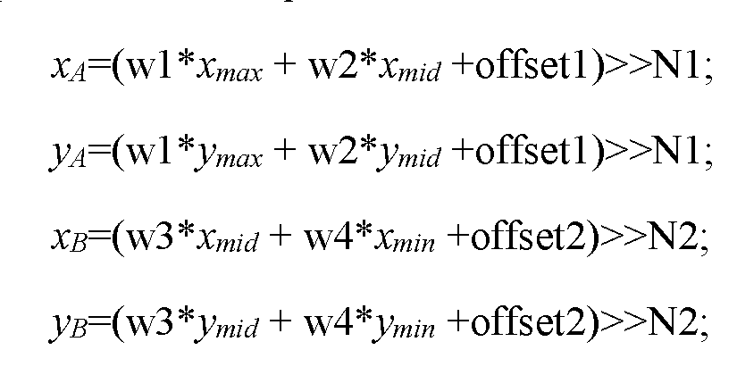
where w1, w2, w3, w4, offset1, offset2, N1 and N2 are predefined parameters; and obtain the parameters a and b based on equations:
 .
.
15. A non-transitory computer readable storage medium, comprising instructions stored therein, wherein, upon execution of the instructions by a processor, the instructions cause the processor to:
derive prediction parameters a and b, using neighboring reconstructed chroma samples and their referred samples, by a parameter deriving process; and
determine whether Local Illumination Compensation (LIC) mode is applied to a current Coding Unit (CU), and upon determining that the LIC mode is applied, derive parameters a2 and b2 for the LIC by execution of the parameter deriving process, and obtain a final LIC predictor based on equation:

wherein
a2 and b2 are instances of the parameters a and b;


16. The non-transitory computer readable storage medium of claim 15, wherein the parameter deriving process implements an algorithm of deriving the parameters a and b using a preset number X of sample pairs, each sample pair comprising an anchor sample that is a neighboring reconstructed sample and its corresponding referred sample.
17. The non-transitory computer readable storage medium of claim 16, wherein the instructions further cause the processor to:
determine whether Cross-Component Linear Model (CCLM) mode is applied to the current Coding Unit (CU), and upon determining that the CCLM mode is applied, derive parameters a1 and b1 for the CCLM by execution of the parameter deriving process, and obtain a final CCLM predictor based on equation:

wherein a1 and b1 are instances of the parameters a and b;

epresents downsampled reconstructed luma samples of the current CU.

18. The non-transitory computer readable storage of claim 17, wherein the preset number X is 3; and the three sample pairs comprise a top sample of left neighboring samples, a bottom sample of the left neighboring samples, and a rightmost sample of above neighboring samples.
19. The non-transitory computer readable storage of claim 18, wherein the anchor sample is a neighboring chroma sample, and the referred sample is a luma sample at a position corresponding to the anchor sample in the CCLM mode; and the referred sample is a reference sample in the reference picture at a position corresponding to the anchor sample in the LIC mode.
20. The non-transitory computer readable storage of claim 17, wherein the preset number X is 4; and the four sample pairs comprise one of the following sample pair sets:
a top sample of left neighboring samples, a leftmost sample of above neighboring samples, a bottom sample of the left neighboring samples, and a rightmost sample of the above neighboring samples;
a quarter of width of the leftmost sample of the above neighboring samples, a quarter of width of the top sample of the left neighboring samples, the bottom sample of the left neighboring samples, and the rightmost sample of the above neighboring samples;
the quarter of width of the leftmost sample of the above neighboring samples, the quarter of width of the top sample of the left neighboring samples, a three quarter of width of the leftmost sample of the above neighboring samples, a three quarter of width of the top sample of the left neighboring samples;
a one-eighth of width of the leftmost sample of the above neighboring samples, a three-eighth of width of the leftmost sample of the above neighboring samples, a five-eighth of width of the leftmost sample of the above neighboring samples, a seven-eighth of width of the leftmost sample of the above neighboring samples; and
a one-eighth of height of the top sample of the left neighboring samples, a three- eighth of height of the top sample of the left neighboring samples, a five-eighth of height of the top sample of the left neighboring samples, a seven-eighth of height of the top sample of the left neighboring samples.
21. The non-transitory computer readable storage of claim 17, wherein the parameter deriving process, upon execution by the processor, causes the processor to:
identify a first sample pair that has a largest referred sample value (xmax, ymax), a second sample pair that has a smallest referred sample value
 , and a third sample pair that has an intermediate referred sample value
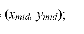
derive a first weighted average of referred sample values xA of the second and third sample pairs, a first weighted average of anchor sample values yA of the second and third sample pairs, a second weighted average of referred sample values xB of the first and third sample pairs, a second weighted average of anchor sample values y
 B of the first and third sample pairs, based on equations:

where w1, w2, w3, w4, offset1, offset2, N1 and N2 are predefined parameters; and obtain the parameters a and b based on equations:
 .
.
Priority Applications (1)
| Application Number | Priority Date | Filing Date | Title |
|---|---|---|---|
| CN202080016731.9A CN113491130B (en) | 2019-01-17 | 2020-01-16 | Method and device for linear model derivation of video encoding and decoding |
Applications Claiming Priority (2)
| Application Number | Priority Date | Filing Date | Title |
|---|---|---|---|
| US201962793869P | 2019-01-17 | 2019-01-17 | |
| US62/793,869 | 2019-01-17 |
Publications (1)
| Publication Number | Publication Date |
|---|---|
| WO2020150535A1 true WO2020150535A1 (en) | 2020-07-23 |
Family
ID=71613454
Family Applications (1)
| Application Number | Title | Priority Date | Filing Date |
|---|---|---|---|
| PCT/US2020/013965 Ceased WO2020150535A1 (en) | 2019-01-17 | 2020-01-16 | Methods and apparatus of linear model derivation for video coding |
Country Status (2)
| Country | Link |
|---|---|
| CN (1) | CN113491130B (en) |
| WO (1) | WO2020150535A1 (en) |
Cited By (3)
| Publication number | Priority date | Publication date | Assignee | Title |
|---|---|---|---|---|
| WO2022178433A1 (en) * | 2021-02-22 | 2022-08-25 | Beijing Dajia Internet Information Technology Co., Ltd. | Improved local illumination compensation for inter prediction |
| WO2023134452A1 (en) * | 2022-01-11 | 2023-07-20 | Beijing Bytedance Network Technology Co., Ltd. | Method, apparatus, and medium for video processing |
| WO2025011483A1 (en) * | 2023-07-07 | 2025-01-16 | Mediatek Inc. | Local illumination compensation with merge slope adjustment |
Families Citing this family (2)
| Publication number | Priority date | Publication date | Assignee | Title |
|---|---|---|---|---|
| CN119732042A (en) * | 2022-08-19 | 2025-03-28 | 抖音视界有限公司 | Expansion of local illumination compensation |
| WO2025002275A1 (en) * | 2023-06-29 | 2025-01-02 | Douyin Vision Co., Ltd. | Method, apparatus, and medium for video processing |
Citations (3)
| Publication number | Priority date | Publication date | Assignee | Title |
|---|---|---|---|---|
| US20130163666A1 (en) * | 2010-09-03 | 2013-06-27 | Dolby Laboratories Licensing Corporation | Method and System for Illumination Compensation and Transition for Video Coding and Processing |
| WO2018039596A1 (en) * | 2016-08-26 | 2018-03-01 | Qualcomm Incorporated | Unification of parameters derivation procedures for local illumination compensation and cross-component linear model prediction |
| WO2019004283A1 (en) * | 2017-06-28 | 2019-01-03 | シャープ株式会社 | Video encoding device and video decoding device |
Family Cites Families (5)
| Publication number | Priority date | Publication date | Assignee | Title |
|---|---|---|---|---|
| EP3313072B1 (en) * | 2015-06-16 | 2021-04-07 | LG Electronics Inc. | Method for predicting block on basis of illumination compensation in image coding system |
| US10419757B2 (en) * | 2016-08-31 | 2019-09-17 | Qualcomm Incorporated | Cross-component filter |
| US10652575B2 (en) * | 2016-09-15 | 2020-05-12 | Qualcomm Incorporated | Linear model chroma intra prediction for video coding |
| US10951912B2 (en) * | 2016-10-05 | 2021-03-16 | Qualcomm Incorporated | Systems and methods for adaptive selection of weights for video coding |
| US10542280B2 (en) * | 2017-01-09 | 2020-01-21 | QUALCOMM Incorpated | Encoding optimization with illumination compensation and integer motion vector restriction |
-
2020
- 2020-01-16 WO PCT/US2020/013965 patent/WO2020150535A1/en not_active Ceased
- 2020-01-16 CN CN202080016731.9A patent/CN113491130B/en active Active
Patent Citations (3)
| Publication number | Priority date | Publication date | Assignee | Title |
|---|---|---|---|---|
| US20130163666A1 (en) * | 2010-09-03 | 2013-06-27 | Dolby Laboratories Licensing Corporation | Method and System for Illumination Compensation and Transition for Video Coding and Processing |
| WO2018039596A1 (en) * | 2016-08-26 | 2018-03-01 | Qualcomm Incorporated | Unification of parameters derivation procedures for local illumination compensation and cross-component linear model prediction |
| WO2019004283A1 (en) * | 2017-06-28 | 2019-01-03 | シャープ株式会社 | Video encoding device and video decoding device |
Non-Patent Citations (2)
| Title |
|---|
| JUNYAN HUO: "Non-CE3:Current luma related-CCLM (CCCLM)], Joint Video Experts Team (JVET) olf ITU-T SG 16 WP 3 and ISO/IEC JTC 1/SC 29/WG 11", JOINT VIDEO EXPERTS TEAM (JVET), 12 October 2018 (2018-10-12), Macao, CN, pages 1 - 3, XP030192756 * |
| SHUAI WAN: "[Non-CE3: CCLM Performance Of Extended Neighboring Region], Joint Video Experts Team (JVET) of ITU-T SG 16 WP 3 and ISO/IEC JTC 1/SC 29/WG 11", JOINT VIDEO EXPERTS TEAM (JVET), no. L0107, Macao, CN, pages 20181012, XP030192752 * |
Cited By (3)
| Publication number | Priority date | Publication date | Assignee | Title |
|---|---|---|---|---|
| WO2022178433A1 (en) * | 2021-02-22 | 2022-08-25 | Beijing Dajia Internet Information Technology Co., Ltd. | Improved local illumination compensation for inter prediction |
| WO2023134452A1 (en) * | 2022-01-11 | 2023-07-20 | Beijing Bytedance Network Technology Co., Ltd. | Method, apparatus, and medium for video processing |
| WO2025011483A1 (en) * | 2023-07-07 | 2025-01-16 | Mediatek Inc. | Local illumination compensation with merge slope adjustment |
Also Published As
| Publication number | Publication date |
|---|---|
| CN113491130A (en) | 2021-10-08 |
| CN113491130B (en) | 2024-02-27 |
Similar Documents
| Publication | Publication Date | Title |
|---|---|---|
| US10390015B2 (en) | Unification of parameters derivation procedures for local illumination compensation and cross-component linear model prediction | |
| US12363338B2 (en) | Methods and apparatus of video coding for deriving affine motion vectors for chroma components | |
| US12470729B2 (en) | Methods and apparatuses for signaling of merge modes in video coding | |
| CN110463202A (en) | Filter information sharing among color components | |
| WO2020150535A1 (en) | Methods and apparatus of linear model derivation for video coding | |
| US12452419B2 (en) | Methods and apparatus of video coding for triangle prediction | |
| CN113545050B (en) | Video encoding and decoding method and device using triangle prediction | |
| CN118872267A (en) | Inter-frame prediction for video coding |
Legal Events
| Date | Code | Title | Description |
|---|---|---|---|
| 121 | Ep: the epo has been informed by wipo that ep was designated in this application |
Ref document number: 20741358 Country of ref document: EP Kind code of ref document: A1 |
|
| NENP | Non-entry into the national phase |
Ref country code: DE |
|
| 122 | Ep: pct application non-entry in european phase |
Ref document number: 20741358 Country of ref document: EP Kind code of ref document: A1 |