WO2020145220A1 - Rotor and motor having the rotor - Google Patents
Rotor and motor having the rotor Download PDFInfo
- Publication number
- WO2020145220A1 WO2020145220A1 PCT/JP2020/000014 JP2020000014W WO2020145220A1 WO 2020145220 A1 WO2020145220 A1 WO 2020145220A1 JP 2020000014 W JP2020000014 W JP 2020000014W WO 2020145220 A1 WO2020145220 A1 WO 2020145220A1
- Authority
- WO
- WIPO (PCT)
- Prior art keywords
- rotor
- end cap
- present
- rotor according
- motor
- Prior art date
- Legal status (The legal status is an assumption and is not a legal conclusion. Google has not performed a legal analysis and makes no representation as to the accuracy of the status listed.)
- Ceased
Links
Images


Classifications
-
- H—ELECTRICITY
- H02—GENERATION; CONVERSION OR DISTRIBUTION OF ELECTRIC POWER
- H02K—DYNAMO-ELECTRIC MACHINES
- H02K19/00—Synchronous motors or generators
- H02K19/02—Synchronous motors
- H02K19/14—Synchronous motors having additional short-circuited windings for starting as asynchronous motors
-
- H—ELECTRICITY
- H02—GENERATION; CONVERSION OR DISTRIBUTION OF ELECTRIC POWER
- H02K—DYNAMO-ELECTRIC MACHINES
- H02K1/00—Details of the magnetic circuit
- H02K1/06—Details of the magnetic circuit characterised by the shape, form or construction
- H02K1/22—Rotating parts of the magnetic circuit
- H02K1/24—Rotor cores with salient poles ; Variable reluctance rotors
- H02K1/246—Variable reluctance rotors
-
- H—ELECTRICITY
- H02—GENERATION; CONVERSION OR DISTRIBUTION OF ELECTRIC POWER
- H02K—DYNAMO-ELECTRIC MACHINES
- H02K21/00—Synchronous motors having permanent magnets; Synchronous generators having permanent magnets
- H02K21/46—Motors having additional short-circuited winding for starting as an asynchronous motor
-
- H—ELECTRICITY
- H02—GENERATION; CONVERSION OR DISTRIBUTION OF ELECTRIC POWER
- H02K—DYNAMO-ELECTRIC MACHINES
- H02K1/00—Details of the magnetic circuit
- H02K1/06—Details of the magnetic circuit characterised by the shape, form or construction
- H02K1/22—Rotating parts of the magnetic circuit
- H02K1/27—Rotor cores with permanent magnets
- H02K1/2706—Inner rotors
- H02K1/272—Inner rotors the magnetisation axis of the magnets being perpendicular to the rotor axis
- H02K1/274—Inner rotors the magnetisation axis of the magnets being perpendicular to the rotor axis the rotor consisting of two or more circumferentially positioned magnets
- H02K1/2753—Inner rotors the magnetisation axis of the magnets being perpendicular to the rotor axis the rotor consisting of two or more circumferentially positioned magnets the rotor consisting of magnets or groups of magnets arranged with alternating polarity
- H02K1/276—Magnets embedded in the magnetic core, e.g. interior permanent magnets [IPM]
Definitions
- the present invention relates to the field of motor technologies, and in particular, to a rotor and a motor having the rotor.
- a synchronous permanent magnet motor or a synchronous reluctance motor is commonly used.
- the synchronous permanent magnet motor needs to be made of an expensive permanent magnet material, and the synchronous reluctance motor has an efficiency bottleneck. Therefore, in recent years, a permanent-magnet auxiliary synchronous reluctance motor has been proposed.
- a permanent magnet such as cheap ferrite is placed in a flux barrier of a rotor of the conventional synchronous reluctance motor, so as to improve the output efficiency of the motor. In this way, the requirement of output efficiency equal to or greater than IE4 level can be met at relatively low costs.
- embodiments of the present invention provide a rotor and a motor having the rotor, so that the end cap does not impede installation of the permanent magnet, and more permanent magnets can be installed into the flux barrier, thereby improving output efficiency of the motor.
- a rotor is provided.
- the rotor includes a rotor core.
- the rotor core rotates about a central axis and is composed of electromagnetic steel plates laminated along an axial direction.
- the rotor core includes a plurality of flux barriers penetrating through the electromagnetic steel plates along the axial direction, and a permanent magnet is accommodated in at least one of the flux barriers.
- An end cap assembly covering at least a part of the rotor core is respectively disposed at two axial ends of the rotor core.
- the end cap assembly includes at least two end caps separately disposed along a circumferential direction.
- a motor is provided, and the motor has the rotor according to the first aspect.
- the end cap assembly is designed to include the at least two end caps separately disposed along the circumferential direction, so that the end cap does not impede installation of the permanent magnet, and more permanent magnets can be installed into the flux barrier, thereby improving the output efficiency of the motor.
- Fig. 1 is a schematic perspective diagram of a rotor according to Embodiment 1 of the present invention.
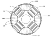
- Fig. 2 is a schematic perspective diagram obtained when the rotor according to Embodiment 1 of the present invention is viewed along an axial direction.
- Fig. 3 is a schematic diagram of an end cap assembly according to Embodiment 1 of the present invention.
- Fig. 4 is a schematic diagram of a conductive path formed by the rotor of an implementation according to Embodiment 1 of the present invention.
- Fig. 5 is another schematic diagram obtained when the rotor according to Embodiment 1 of the present invention is viewed along the axial direction.
- Fig. 1 is a schematic perspective diagram of a rotor according to Embodiment 1 of the present invention.
- Fig. 2 is a schematic perspective diagram obtained when the rotor according to Embodiment 1 of the present invention is viewed along an axial direction.
- Fig. 3 is a schematic diagram of an end cap assembly according to
- FIG. 6 is a schematic diagram obtained before the end cap assembly is formed on the rotor according to Embodiment 1 of the present invention.
- Fig. 7 is a schematic diagram of a manner in which an end cap is in contact with a conductive component when the end cap assembly is formed on the rotor according to Embodiment 1 of the present invention.
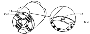
- Fig. 8 is another schematic perspective diagram of the rotor according to Embodiment 1 of the present invention.
- the singular form such as “a”, “the”, and the like includes the plural form, and should be broadly understood as “one kind” or “one category” rather than limited to “one”.
- the term “the” should be understood to include both the singular form and the plural form, unless the context clearly indicates otherwise.
- the term “according to” should be understood to mean “at least in part according to”, and the term “based on” should be understood to mean “at least in part based on”, unless the context clearly indictates otherwise.
- a center line around which a rotor core of a motor rotates is referred to as a "central axis”
- a direction that is the same as or parallel to a direction in which the central axis extends is referred to as an "axial direction”
- a radial direction that is centered on the central axis is referred to as a “radial direction”
- a direction around the central axis is referred to as a "circumferential direction”.
- Embodiment 1 provides a rotor.
- the rotor is applied to a motor, such as a permanent-magnet auxiliary self-starting synchronous reluctance motor.
- FIG. 1 is a schematic perspective diagram of the rotor according to the present embodiment.
- FIG. 2 is a schematic diagram obtained when the rotor according to the present embodiment is viewed along the axial direction.
- FIG. 3 is a schematic diagram of an end cap assembly according to the present embodiment.
- the rotor 10 has a rotor core 11, and the rotor core 11 rotates about a central axis O-O’ and is composed of electromagnetic steel plates laminated along the axial direction.
- the rotor core 11 includes a plurality of flux barriers 11s penetrating through the electromagnetic steel plates along the axial direction, and a permanent magnet 12 is accommodated in at least one of the flux barriers.
- An end cap assembly 13 covering at least a part of the rotor core 11 is respectively disposed at two axial ends of the rotor core 11.
- the end cap assembly 13 includes at least two end caps separately disposed along the circumferential direction.
- FIG. 1 and FIG. 2 show a case in which the end cap assembly 13 includes four end caps 13-1, 13-2, 13-3, and 13-4, but the present embodiment is not limited thereto.
- a quantity of the end caps included in the end cap assembly 13 may be set according to the actual requirement.
- a set of flux barriers and a set of permanent magnets that are arranged along the radial direction are marked with reference numbers 11s and 12 in FIG. 1 and FIG. 2 merely by way of example.
- FIG. 1 four sets of electromagnetic barriers 11s and four sets of permanent magnets 12 are disposed.
- Other sets of electromagnetic barriers and permanent magnets that are unmarked are disposed in a manner same as that in which the marked electromagnetic barriers and permanent magnets are disposed.
- the end cap assembly 13 is designed to include at least two end caps separately disposed along the circumferential direction, so that each end cap can be disposed at a location freely in the circumferential direction, and can be located away from a location at which the permanent magnet 12 is inserted along the axial direction. Therefore, the end cap does not impede installation of the permanent magnet 12, so that more permanent magnets 12 can be installed into the flux barrier 11s, thereby improving output efficiency of the motor in which the rotor 10 is located.
- the permanent magnet 12 may be exposed from adjacent end caps (for example, from the end cap 13-1 and the end cap13-2, from the end cap 13-2 and the end cap 13-3, from the end cap 13-3 and the end cap 13-4, or from the end cap 13-4 and the end cap 13-1).
- the permanent magnet 12 may be exposed from adjacent end caps through setting of a distance between the adjacent end caps. In other words, the distance between adjacent end caps may be set to such a value that the end cap does not impede insertion of the permanent magnet 12 into the flux barrier 11s.
- the permanent magnet 12 may be accommodated in each of the plurality of flux barriers 11s. Therefore, more permanent magnets 12 can be installed into the flux barrier 11s of the rotor, thereby improving output efficiency of the motor.
- the present embodiment is not limited thereto, and the permanent magnet 12 may be accommodated in only some of the flux barriers 11s.
- the end caps 13-1, 13-2, 13-3, and 13-4 may be disposed at equal intervals along the circumferential direction.
- the present embodiment is not limited thereto, and the end caps 13-1, 13-2, 13-3, and 13-4 may also be disposed at different intervals along the circumferential direction, or some end caps may be disposed at equal intervals while other end caps are disposed at different intervals along the circumferential direction.
- a specific disposing manner may be determined according to the actual requirement.
- the end caps 13-1, 13-2, 13-3, and 13-4 may be made of materials that are conductive but not magnetic, such as aluminum or copper.
- a conductive component 14 that is conductive but not magnetic may be further accommodated in the plurality of flux barriers 11s, and the conductive component 14 is connected to adjacent end caps. Similar to a manner of marking the flux barrier 11s and the permanent magnet 12, a set of conductive components 14 arranged in the radial direction is marked in FIG. 1 and FIG. 2 merely by way of example.
- the conductive component 14 is configured to generate an induction torque, and the conductive component 14 and the end cap connected to the conductive component 14 jointly form a conductive path of an induced current.
- the induced current generated during rotation of the rotor 10 can flow through the conductive path, so that the motor in which the rotor 10 is located can realize a self-starting characteristic.
- the conductive component 14 may be formed in the following manner: a jig (a shape and a size of the jig are corresponding to those of the permanent magnet 12) is inserted into the flux barrier 11s, a liquid material of the conductive component 14 is injected into the remaining space of the flux barrier 11s, and then the liquid material is solidified, thereby forming a solid conductive component 14 in the flux barrier 11s. Afterwards, the jig may be pulled out of the flux barrier 11s to form space for inserting a permanent magnet, and the permanent magnet 12 is inserted into the space.
- a jig a shape and a size of the jig are corresponding to those of the permanent magnet 12
- the conductive component 14 is accommodated in each flux barrier 11s. Therefore, adjacent end caps are connected through each of a plurality of conductive components 14, thereby forming a plurality of conductive paths. In this way, the motor can have a high load capacity during self-starting, so that the motor has a good self-starting characteristic.
- FIG. 4 is a schematic diagram of the conductive path formed according to this implementation. As shown in FIG. 4, adjacent end caps 13-2 and 13-3 are conducted using each conductive component 14 in each flux barrier 11s, thereby forming a plurality of conductive paths Pa -> P1 -> Pb, Pa -> P2 -> Pb, and Pa -> P3 -> Pb.
- FIG. 5 is another schematic diagram obtained when the rotor according to the present embodiment is viewed in the axial direction.
- the conductive component 14 is accommodated only in the radially outermost flux barrier of the plurality of flux barriers 11s, and the conductive component 14 is not accommodated in other flux barriers. Therefore, the adjacent end caps are conducted using only the radially outermost flux barrier of the plurality of flux barriers 11s. That is, the adjacent end caps are conducted using the conductive component 14 in the radially outermost flux barrier of the plurality of flux barriers 11s, thereby forming a conductive path.
- the induced current can still flow through a conductive path, and therefore, the motor still has a relatively high load capacity during self-starting.
- the conductive component 14 is accommodated only in the radially outermost flux barrier, a permanent magnet of a maximum volume can be filled in the flux barriers other than the radially outermost flux barrier, thereby further improving output efficiency of the motor.
- the motor can have both a high load self-starting capacity and high output efficiency.
- the end cap may be in contact with a part of the conductive component 14, so that the end cap can be conducted to the conductive component 14, thereby forming a conductive path of the induced current.
- FIG. 6 is a schematic diagram obtained before the end cap assembly is formed on the rotor.
- FIG. 7 is a schematic diagram of a manner in which the end cap is in contact with the conductive component 14 when the end cap assembly is formed on the rotor. As shown in FIG. 6 and FIG. 7, the end caps 13-1, 13-2, 13-3, and 13-4 are in contact with a part of the conductive component 14 shown using dashed lines.
- each end cap has a plurality of contact portions 13t in contact with the conductive component 14.
- Each contact portion 13t is at a location indicated using dashed lines in FIG. 7, and an area of each contact portion 13t may be determined according to the actual requirement.
- the liquid material of the conductive component 14 needs to be injected into flux barrier space corresponding to the dashed-line location in FIG. 7. If the flux barrier space is pretty small (that is, the area of the contact portion is pretty small), it may be difficult to inject the liquid material into the flux barrier space. Consequently, the end cap cannot be in contact with the conductive component 14 in a desired manner.
- the area of each contact portion 13t may be set to be greater than four square millimetres, so that the liquid material of the conductive component 14 can be reliably injected into the flux barrier space corresponding to the dashed-line location in FIG. 7, and the end cap can be in contact with the conductive component 14 in a desired manner, thereby forming a corresponding conductive path.
- FIG. 8 is another schematic perspective diagram of the rotor according to the present embodiment.
- a hole 15 may be formed on the end cap. Heat dissipation and/or maintaining of dynamic balance can be realized through formation of the hole 15.
- the hole 15 may be formed as a through hole.
- the hole 15 may be formed as a through hole or as a non-through hole.
- the hole 15 may be formed as a through hole. A size of the hole and a depth of the non-through hole may be determined according to the requirement for heat dissipation and/or maintaining of dynamic balance.
- the hole 15 is formed on one end cap (13-2), but the present embodiment is not limited thereto.
- the hole 15 may also be formed on a plurality of end caps.
- the hole 15 is formed on a side surface of the end cap, but the present embodiment is not limited thereto.
- the hole 15 may also be formed on other locations of the end cap.
- a shape of the end cap may be designed according to the actual requirement.
- the end cap is designed to be roughly arc-shaped when viewed along the axial direction.
- the present embodiment is not limited thereto, and the end cap may be designed to be circular, polygonal, or the like.
- the end cap assembly is designed to include at least two end caps separately disposed along the circumferential direction, so that the end cap does not impede installation of the permanent magnet, and more permanent magnets can be installed into the flux barrier, thereby improving output efficiency of the motor.
- Embodiment 2 provides a motor having a stator and a rotor.
- the rotor may be as described in Embodiment 1, and the descriptions thereof are omitted herein.
- the motor may also include other components. For details, please refer to the conventional art.
- the motor in the present embodiment may be a permanent-magnet auxiliary self-starting synchronous reluctance motor.
- the end cap does not impede installation of the permanent magnet, and more permanent magnets can be installed into the flux barrier, thereby improving output efficiency of the motor.
Landscapes
- Engineering & Computer Science (AREA)
- Power Engineering (AREA)
- Permanent Field Magnets Of Synchronous Machinery (AREA)
Abstract
Description
Claims (12)
- A rotor, comprising:
a rotor core rotating about a central axis and being composed of a plurality of electromagnetic steel plates laminated along an axial direction, the rotor core comprising a plurality of flux barriers penetrating through the electromagnetic steel plates along the axial direction, and a permanent magnet being accommodated in at least one of the flux barriers; and
an end cap assembly covering at least a part of the rotor core and being respectively disposed at two axial ends of the rotor core, wherein
the end cap assembly comprises at least two end caps separately disposed along a circumferential direction. - The rotor according to claim 1, wherein
the at least two end caps are disposed at equal intervals along the circumferential direction. - The rotor according to claim 1, wherein
the permanent magnet is exposed from adjacent end caps. - The rotor according to claim 1, wherein
the permanent magnet is accommodated in each of the flux barriers. - The rotor according to claim 1, wherein
the end cap is made of a material that is conductive and not magnetic. - The rotor according to claim 1, wherein
a conductive component that is conductive and not magnetic is further accommodated in the plurality of flux barriers, the conductive component being connected to the adjacent end caps. - The rotor according to claim 6, wherein
the conductive component is accommodated in each of the flux barriers. - The rotor according to claim 6, wherein
the conductive component is accommodated in a radially outermost flux barrier of the plurality of flux barriers. - The rotor according to any one of claims 6 to 8, wherein
each of the end caps comprises a plurality of contact portions in contact with the conductive component, an area of each of the contact portions being greater than 4 square millimetres. - The rotor according to claim 1, wherein
a hole is formed on the end cap. - The rotor according to claim 1, wherein
the end cap is arc-shaped when viewed along the axial direction. - A motor, comprising a stator and the rotor according to any one of claims 1 to 11.
Applications Claiming Priority (2)
| Application Number | Priority Date | Filing Date | Title |
|---|---|---|---|
| CN201920032514.3U CN209233589U (en) | 2019-01-09 | 2019-01-09 | Rotor and motor with the rotor |
| CN201920032514.3 | 2019-01-09 |
Publications (1)
| Publication Number | Publication Date |
|---|---|
| WO2020145220A1 true WO2020145220A1 (en) | 2020-07-16 |
Family
ID=67510241
Family Applications (1)
| Application Number | Title | Priority Date | Filing Date |
|---|---|---|---|
| PCT/JP2020/000014 Ceased WO2020145220A1 (en) | 2019-01-09 | 2020-01-06 | Rotor and motor having the rotor |
Country Status (2)
| Country | Link |
|---|---|
| CN (1) | CN209233589U (en) |
| WO (1) | WO2020145220A1 (en) |
Families Citing this family (2)
| Publication number | Priority date | Publication date | Assignee | Title |
|---|---|---|---|---|
| TWI729648B (en) * | 2019-12-23 | 2021-06-01 | 綠達光電股份有限公司 | Modular motor rotor and modular motor rotor structure |
| JP7725250B2 (en) * | 2021-06-17 | 2025-08-19 | ニデック株式会社 | Synchronous reluctance motor |
Citations (3)
| Publication number | Priority date | Publication date | Assignee | Title |
|---|---|---|---|---|
| US4490638A (en) * | 1983-08-08 | 1984-12-25 | Mcgraw-Edison Company | Salient pole rotor with amortisseur winding |
| EP3160013A1 (en) * | 2015-10-22 | 2017-04-26 | ABB Schweiz AG | Permanent magnet rotor for rotating electric machines and method for manufacturing such rotor |
| CN107834800A (en) * | 2017-11-08 | 2018-03-23 | 卧龙电气集团股份有限公司 | One kind is without controller self-starting permanent magnetism assist in synchronization reluctance motor |
-
2019
- 2019-01-09 CN CN201920032514.3U patent/CN209233589U/en active Active
-
2020
- 2020-01-06 WO PCT/JP2020/000014 patent/WO2020145220A1/en not_active Ceased
Patent Citations (4)
| Publication number | Priority date | Publication date | Assignee | Title |
|---|---|---|---|---|
| US4490638A (en) * | 1983-08-08 | 1984-12-25 | Mcgraw-Edison Company | Salient pole rotor with amortisseur winding |
| EP3160013A1 (en) * | 2015-10-22 | 2017-04-26 | ABB Schweiz AG | Permanent magnet rotor for rotating electric machines and method for manufacturing such rotor |
| CN108141070A (en) | 2015-10-22 | 2018-06-08 | Abb瑞士股份有限公司 | Method for the PM rotor of electric rotating machine and for manufacturing the rotor |
| CN107834800A (en) * | 2017-11-08 | 2018-03-23 | 卧龙电气集团股份有限公司 | One kind is without controller self-starting permanent magnetism assist in synchronization reluctance motor |
Also Published As
| Publication number | Publication date |
|---|---|
| CN209233589U (en) | 2019-08-09 |
Similar Documents
| Publication | Publication Date | Title |
|---|---|---|
| RU2689311C1 (en) | Rotating electrical machine | |
| US6630762B2 (en) | Permanent magnet rotor and method of making the same | |
| US10855126B2 (en) | Electric motor and air conditioner | |
| KR101102748B1 (en) | Induction electric motor and hermetic comporessor | |
| US7948138B2 (en) | Rotor | |
| US6025667A (en) | Permanent magnet rotor type electric motor with different permanent magnet materials | |
| CN110138117A (en) | Synchronous reluctance motor rotor structure, motor and manufacturing method of rotor structure | |
| CN113193674B (en) | Rotor assembly and self-starting permanent magnet synchronous reluctance motor | |
| US20050275302A1 (en) | Rotor magnet placement in interior permanent magnet machines | |
| US10749385B2 (en) | Dual magnetic phase material rings for AC electric machines | |
| JP2001025209A (en) | Motor rotor | |
| EP2658091A2 (en) | Rotor assembly | |
| CN210839094U (en) | Rotor structure of direct-start synchronous reluctance motor and motor | |
| CN209805521U (en) | Rotor structure of direct-start synchronous reluctance motor and motor | |
| CN106357028A (en) | Permanent magnet synchronous motor rotor and permanent magnet synchronous motor | |
| CN110112848B (en) | Self-starting synchronous reluctance motor rotor structure and motor with same | |
| EP1670119A1 (en) | Motor with Improved flux distribution | |
| KR20140039128A (en) | Permanent magnet-embedded motor and rotor thereof | |
| JPH0833246A (en) | Permanent magnet type synchronous rotating electric machine rotor | |
| US20210211001A1 (en) | Rotor and motor having rotor | |
| CN209805522U (en) | Self-starting synchronous reluctance motor rotor structure and motor with same | |
| CN209233589U (en) | Rotor and motor with the rotor | |
| JP2022121978A (en) | Rotary electric machine | |
| EP3780349B1 (en) | Motor rotor and permanent magnet motor | |
| CN108711968A (en) | Rotor assembly and motor |
Legal Events
| Date | Code | Title | Description |
|---|---|---|---|
| 121 | Ep: the epo has been informed by wipo that ep was designated in this application |
Ref document number: 20701127 Country of ref document: EP Kind code of ref document: A1 |
|
| ENP | Entry into the national phase |
Ref document number: 2020571882 Country of ref document: JP Kind code of ref document: A |
|
| NENP | Non-entry into the national phase |
Ref country code: DE |
|
| NENP | Non-entry into the national phase |
Ref country code: JP |
|
| 122 | Ep: pct application non-entry in european phase |
Ref document number: 20701127 Country of ref document: EP Kind code of ref document: A1 |