WO2020145000A1 - 通信制御方法 - Google Patents
通信制御方法 Download PDFInfo
- Publication number
- WO2020145000A1 WO2020145000A1 PCT/JP2019/048235 JP2019048235W WO2020145000A1 WO 2020145000 A1 WO2020145000 A1 WO 2020145000A1 JP 2019048235 W JP2019048235 W JP 2019048235W WO 2020145000 A1 WO2020145000 A1 WO 2020145000A1
- Authority
- WO
- WIPO (PCT)
- Prior art keywords
- communication device
- cell
- control method
- communication
- bandwidth portion
- Prior art date
- Legal status (The legal status is an assumption and is not a legal conclusion. Google has not performed a legal analysis and makes no representation as to the accuracy of the status listed.)
- Ceased
Links
Images






Classifications
-
- H—ELECTRICITY
- H04—ELECTRIC COMMUNICATION TECHNIQUE
- H04W—WIRELESS COMMUNICATION NETWORKS
- H04W74/00—Wireless channel access
- H04W74/08—Non-scheduled access, e.g. ALOHA
- H04W74/0808—Non-scheduled access, e.g. ALOHA using carrier sensing, e.g. carrier sense multiple access [CSMA]
-
- H—ELECTRICITY
- H04—ELECTRIC COMMUNICATION TECHNIQUE
- H04W—WIRELESS COMMUNICATION NETWORKS
- H04W16/00—Network planning, e.g. coverage or traffic planning tools; Network deployment, e.g. resource partitioning or cells structures
- H04W16/14—Spectrum sharing arrangements between different networks
-
- H—ELECTRICITY
- H04—ELECTRIC COMMUNICATION TECHNIQUE
- H04W—WIRELESS COMMUNICATION NETWORKS
- H04W24/00—Supervisory, monitoring or testing arrangements
- H04W24/08—Testing, supervising or monitoring using real traffic
-
- H—ELECTRICITY
- H04—ELECTRIC COMMUNICATION TECHNIQUE
- H04W—WIRELESS COMMUNICATION NETWORKS
- H04W48/00—Access restriction; Network selection; Access point selection
- H04W48/16—Discovering, processing access restriction or access information
-
- H—ELECTRICITY
- H04—ELECTRIC COMMUNICATION TECHNIQUE
- H04W—WIRELESS COMMUNICATION NETWORKS
- H04W76/00—Connection management
- H04W76/10—Connection setup
- H04W76/18—Management of setup rejection or failure
-
- H—ELECTRICITY
- H04—ELECTRIC COMMUNICATION TECHNIQUE
- H04W—WIRELESS COMMUNICATION NETWORKS
- H04W76/00—Connection management
- H04W76/10—Connection setup
- H04W76/19—Connection re-establishment
Definitions
- the present disclosure relates to a communication control method in a mobile communication system.
- LAA Long Term Evolution Advanced Mobile Broadband
- NR New Radio
- 5G fifth-generation
- NR-U is supposed to be able to use the unlicensed band alone without using the unlicensed band together with the licensed band. Under such an assumption, it is considered that a new function that LAA does not have is required.
- the communication control method is a method for a first communication device to perform wireless communication with a second communication device in a cell operated in an unlicensed band.
- the communication control method sets a first bandwidth portion and a second bandwidth portion having a bandwidth narrower than the first bandwidth portion within a carrier frequency of the cell; and the first communication device.
- the communication control method is a method used in a cell operated in an unlicensed band.
- the physical layer of the first communication device measures the interference wave power for the unlicensed band. By doing so, it is possible to evaluate whether or not there is an interfering wave, and even if there is no data to be transmitted from the first communication device to the second communication device, the first communication device In response to an instruction from the upper layer to the physical layer, the physical layer performs the evaluation, and the result of the evaluation performed in response to the instruction from the physical layer to the upper layer, including.
- a user apparatus in an RRC connected state measures a jamming power of a carrier frequency of the cell to thereby determine a congestion degree of the cell. Evaluating, the user equipment detects a radio link failure based on the evaluated congestion degree, and, in response to the detection of the radio link failure, the cell while maintaining the RRC connected state Performing an RRC reestablishment process by selecting a different cell.
- a user apparatus in an RRC idle state or an RRC inactive state has a higher priority than a priority set in a carrier frequency of the cell.
- a communication control method in a cell operated in an unlicensed band, a user apparatus in an RRC idle state or an RRC inactive state interferes with the unlicensed band only when a predetermined condition is satisfied. Includes assessing congestion by measuring wave power.
- the predetermined condition is that the received power of a radio signal received by the user equipment from the cell is below a threshold value, and the user equipment performs a tracking area update process or a RAN notification area update process via the cell.
- a communication control method in a cell operated in an unlicensed band, when data to be transmitted from a first communication device located in the cell to a second communication device is generated, the first communication device is , Performing LBT (Listen Before Talk) before transmitting the data, measuring the number of times the first communication device has failed the LBT, and causing the first communication device to fail the LBT. Detecting a wireless link failure between the first communication device and the second communication device based on the number of times the communication control method is performed.
- LBT Listen Before Talk
- Mobile communication system First, the configuration of the mobile communication system according to the embodiment will be described.
- the mobile communication system according to an embodiment is a 3GPP 5G system
- LTE may be at least partially applied to the mobile communication system.
- FIG. 1 is a diagram showing a configuration of a mobile communication system according to an embodiment.
- the mobile communication system includes a user equipment (UE: User Equipment) 100, a 5G radio access network (NG-RAN: Next Generation Radio Access Network) 10, and a 5G core network (5GC: 5G). Core Network) 20 and.
- UE User Equipment
- NG-RAN Next Generation Radio Access Network
- 5G core network 5G core network
- the UE 100 is a movable device.
- the UE 100 may be any device as long as it is a device used by the user.
- the UE 100 is a mobile phone terminal (including a smartphone), a tablet terminal, a notebook PC, a communication module (including a communication card or a chipset), a sensor or a device provided in the sensor, a vehicle or a device provided in the vehicle (vehicle UE). ), or a device or an apparatus (Aerial UE) provided on the device.
- the NG-RAN 10 includes a base station (called “gNB” in the 5G system) 200.
- the gNB 200 may also be called an NG-RAN node.
- the gNBs 200 are connected to each other via an Xn interface which is an interface between base stations.
- the gNB 200 manages one or a plurality of cells.
- the gNB 200 performs wireless communication with the UE 100 that has established a connection with its own cell.
- the gNB 200 has a radio resource management (RRM) function, a user data (hereinafter simply referred to as “data”) routing function, and/or a measurement control function for mobility control/scheduling.
- RRM radio resource management
- Cell is used as a term indicating a minimum unit of a wireless communication area.
- the “cell” is also used as a term indicating a function or resource for performing wireless communication with the UE 100.
- One cell belongs to one carrier frequency.
- the gNB may be connected to EPC (Evolved Packet Core), which is the LTE core network, or the LTE base station may be connected to 5GC. Further, the LTE base station and the gNB may be connected via an inter-base station interface.
- EPC Evolved Packet Core
- the 5GC20 includes AMF(Access and Mobility Management Function) and UPF(User Plane Function)300.
- the AMF performs various mobility controls for the UE 100.
- the AMF manages information on the area in which the UE 100 is located by communicating with the UE 100 using NAS (Non-Access Stratum) signaling.
- the UPF controls data transfer.
- the AMF and UPF are connected to the gNB 200 via the NG interface which is an interface between the base station and the core network.
- FIG. 2 is a diagram showing a configuration of the UE 100 (user device).
- the UE 100 includes a reception unit 110, a transmission unit 120, and a control unit 130.
- the receiving unit 110 performs various types of reception under the control of the control unit 130.
- the receiver 110 includes an antenna and a receiver.
- the receiver converts a radio signal received by the antenna into a baseband signal (received signal) and outputs the baseband signal to the control unit 130.
- the transmission unit 120 performs various types of transmission under the control of the control unit 130.
- the transmitter 120 includes an antenna and a transmitter.
- the transmitter converts the baseband signal (transmission signal) output by the control unit 130 into a radio signal and transmits the radio signal from the antenna.
- the control unit 130 performs various controls in the UE 100.
- the control unit 130 includes at least one processor and at least one memory electrically connected to the processor.
- the memory stores a program executed by the processor and information used for processing by the processor.
- the processor may include a baseband processor and a CPU (Central Processing Unit).
- the baseband processor performs modulation/demodulation and coding/decoding of the baseband signal.
- the CPU executes programs stored in the memory to perform various kinds of processing.
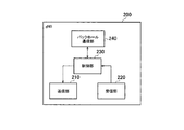
- FIG. 3 is a diagram showing a configuration of the gNB 200 (base station).
- the gNB 200 includes a transmission unit 210, a reception unit 220, a control unit 230, and a backhaul communication unit 240.
- the transmission unit 210 performs various types of transmission under the control of the control unit 230.
- the transmitter 210 includes an antenna and a transmitter.
- the transmitter converts the baseband signal (transmission signal) output by the control unit 230 into a radio signal and transmits the radio signal from the antenna.
- the receiving unit 220 performs various types of reception under the control of the control unit 230.
- the receiver 220 includes an antenna and a receiver.
- the receiver converts a radio signal received by the antenna into a baseband signal (received signal) and outputs the baseband signal to the control unit 230.
- the control unit 230 performs various controls in the gNB 200.
- the controller 230 includes at least one processor and at least one memory electrically connected to the processor.
- the memory stores a program executed by the processor and information used for processing by the processor.
- the processor may include a baseband processor and a CPU.
- the baseband processor performs modulation/demodulation and coding/decoding of the baseband signal.
- the CPU executes programs stored in the memory to perform various kinds of processing.
- the backhaul communication unit 240 is connected to an adjacent base station via an interface between base stations.
- the backhaul communication unit 240 is connected to the AMF/UPF 300 via a base station-core network interface.
- the gNB may be composed of a CU (Central Unit) and a DU (Distributed Unit) (that is, functionally divided), and both units may be connected by an F1 interface.
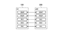
- FIG. 4 is a diagram showing a configuration of a protocol stack of a wireless interface of a user plane that handles data.
- the user plane radio interface protocol includes a physical (PHY) layer, a MAC (Medium Access Control) layer, an RLC (Radio Link Control) layer, and a PDCP (Packet Data Convergence Protocol) layer. It has an SDAP (Service Data Adaptation Protocol) layer.
- PHY physical
- MAC Medium Access Control
- RLC Radio Link Control
- PDCP Packet Data Convergence Protocol
- SDAP Service Data Adaptation Protocol
- PHY layer performs encoding/decoding, modulation/demodulation, antenna mapping/demapping, and resource mapping/demapping. Data and control information are transmitted via the physical channel between the PHY layer of the UE 100 and the PHY layer of the gNB 200.
- the MAC layer performs data priority control, retransmission processing by hybrid ARQ (HARQ), random access procedure, etc. Data and control information are transmitted via the transport channel between the MAC layer of the UE 100 and the MAC layer of the gNB 200.
- the MAC layer of gNB200 includes a scheduler. The scheduler determines uplink and downlink transport formats (transport block size, modulation/coding scheme (MCS)) and resource blocks to be allocated to the UE 100.
- MCS modulation/coding scheme
- the RLC layer uses the functions of the MAC layer and PHY layer to transmit data to the RLC layer on the receiving side. Data and control information are transmitted via the logical channel between the RLC layer of the UE 100 and the RLC layer of the gNB 200.
- the PDCP layer performs header compression/decompression and encryption/decryption.
- the SDAP layer maps the IP flow, which is the unit in which the core network performs QoS control, and the radio bearer, which is the unit in which AS (Access Stratum) performs QoS control.
- SDAP may be omitted.
- FIG. 5 is a diagram showing a configuration of a protocol stack of a radio interface of a control plane that handles signaling (control signal).
- the protocol stack of the radio interface of the control plane has an RRC (Radio Resource Control) layer and a NAS (Non-Access Stratum) layer instead of the SDAP layer shown in FIG.
- RRC signaling for various settings is transmitted between the RRC layer of the UE 100 and the RRC layer of the gNB 200.
- the RRC layer controls logical channels, transport channels and physical channels according to establishment, re-establishment and release of radio bearers.
- RRC connection connection between the RRC of the UE 100 and the RRC of the gNB 200
- the UE 100 is in the RRC connected state.
- RRC connection no connection between the RRC of the UE 100 and the RRC of the gNB 200
- the UE 100 is in the RRC idle state.
- the RRC connection is suspended (suspended), the UE 100 is in the RRC inactive state.
- the NAS layer which is located above the RRC layer, performs session management, mobility management, etc.
- NAS signaling is transmitted between the NAS layer of the UE 100 and the NAS layer of the AMF 300.
- the UE 100 has an application layer and the like in addition to the wireless interface protocol.
- the first embodiment will be described on the premise of the mobile communication system described above.
- the following embodiments assume NR-U that uses an unlicensed band in NR communication.
- the NR-U may use the unlicensed band alone without using the unlicensed band together with the licensed band.
- the unlicensed band may have an interference wave (interference wave) from another system such as a wireless LAN, and may interfere with another system from the communication device (UE100, gNB200) of the mobile communication system. Therefore, in the unlicensed band, the communication device (UE100, gNB200) is obliged to apply the LBT (Listen Before Talk) before transmitting.
- interference wave interference wave
- the communication device UE100, gNB200
- the UE 100 and the gNB 200 determine the interference power of this channel in order to evaluate whether there is an interference wave, that is, whether the channel is idle or busy. Measure and monitor.
- the communication device can perform transmission.
- the jammer i.e. the channel is evaluated to be busy
- the communication device cannot perform the transmission.
- the communication device considers that the case where it is evaluated that there is no interference wave is LBT success, and the case where it is evaluated that there is interference wave is LBT failure. Therefore, in the unlicensed band, there is a problem that the communication device is limited in the opportunities for transmission.
- uplink communication will be mainly described, but the first embodiment can also be applied to the downlink or the side link.
- the side link refers to a direct communication interface between UEs.
- the communication control method is a method for a first communication device to perform wireless communication with a second communication device in a cell operated in an unlicensed band.
- the first communication device is the UE 100 and the second communication device is the gNB 200.
- the first communication device is gNB200 and the second communication device is UE100.
- the first communication device and the second communication device are different UEs 100.
- At least the first bandwidth portion and the second bandwidth portion having a narrower bandwidth than the first bandwidth portion are set within the carrier frequency of the cell.
- a second bandwidth portion having a narrower bandwidth than the second bandwidth portion may be further set.
- the bandwidth part is a part of the frequency part of the entire band of the cell. In NR, such a bandwidth portion is called a BWP (Bandwidth part).
- the BWP is set from the gNB 200 to the UE 100, and switching from one BWP to another BWP is controlled by the gNB 200. For example, when two BWPs are set in the UE 100 and one BWP is active and the other BWP is inactive, the gNB 200 can control the active BWP to switch from one BWP to the other BWP.
- subcarrier spacing and cyclic prefix can be variably set for each BWP.
- Switching between BWPs is performed by a DCI (Downlink Control Information) or a deactivation timer transmitted on a PDCCH (Physical Downlink Control Channel). If the serving cell has an inactivity timer configured, the active BWP switches from the network to the configured default BWP when the inactivity timer associated with that cell expires.
- DCI Downlink Control Information
- PDCCH Physical Downlink Control Channel
- FIG. 6 is a diagram showing an example of the BWP set in the UE 100.
- FIG. 6 shows an example in which four BWPs are set for the uplink.
- the four BWPs have the largest bandwidth, the BWP #1 having the second largest bandwidth, the BWP #2 having the second largest bandwidth, and the BWP #3 having the third largest bandwidth.
- the gNB 200 is set so that the BWPs overlap in the frequency direction.
- each BWP has a bandwidth that is an integral multiple of the bandwidth of the narrowest BWP #4
- the bandwidth of each BWP need not be an integral multiple of the narrowest BWP. ..
- the subcarrier intervals of each BWP may be the same or different. At least one BWP of the plurality of BWPs may not overlap with another BWP in the frequency direction. Each of the plurality of BWPs may not overlap each other in the frequency direction.
- FIG. 7 is a diagram showing a communication control method according to the first embodiment. In the operation illustrated in FIG. 7, it is assumed that the UE 100 is in the RRC connected state.
- a plurality of BWPs as shown in FIG. 6 are set from the gNB 200 to the UE 100.
- the BWP may be set by SIB (System Information Block), which is broadcast RRC signaling, or may be set by unicast RRC signaling (hereinafter, referred to as dedicated RRC signaling).
- SIB System Information Block
- dedicated RRC signaling unicast RRC signaling
- the gNB 200 activates a plurality of set BWPs. For example, the gNB 200 may transmit the DCI that activates a plurality of set BWPs to the UE 100, or may operate the inactivity timer of each BWP at the same time. After that, the gNB 200 monitors the uplink transmission from the UE 100 (that is, attempts decoding) for each BWP.
- the uplink transmission may be a PUSCH (Physical Uplink Shared Channel) transmission, a PUCCH (Physical Uplink Control Channel) transmission, and/or another uplink channel transmission.
- PUSCH Physical Uplink Shared Channel
- PUCCH Physical Uplink Control Channel
- the UE 100 measures the interference wave power for the set and active BWP.
- UE100 measures an interference wave power for every predetermined frequency unit about the widest BWP.
- the predetermined frequency unit refers to the narrowest BWP bandwidth, resource block bandwidth, or subcarrier bandwidth.
- the resource block is composed of a plurality of subcarriers.
- the UE 100 measures the interfering wave power for each BWP #4 bandwidth within the BWP #1 band. Specifically, the interference wave power is measured for each of the bands F1 to F4 shown in FIG. Then, the UE 100 acquires the measurement result of BWP#1 by integrating the interference wave powers of F1 to F4, and acquires the measurement result of BWP#2 by integrating the interference wave powers of F1 to F3. Further, the measurement result of BWP#3 is obtained by integrating the interference wave powers of F1 and F2, and the interference wave power of F1 is obtained as it is as the measurement result of BWP#4. This makes it possible to efficiently obtain the measurement results for four BWPs only by measuring the interference wave power for one BWP. Even when the measurement is performed in resource block units or subcarrier units, the measurement result of each BWP can be obtained by the same method.
- step S103 the UE 100 evaluates whether or not there is an interfering wave in the BWP#1 based on the measurement result obtained for the widest BWP#1. For example, the UE 100 compares the measurement result obtained for BWP#1 with the threshold value set from the gNB 200, and if the measurement result is less than the threshold value, evaluates that there is no interfering wave (that is, LBT success). In this case, BWP#1 can be used. On the other hand, if the measurement result is greater than or equal to the threshold value, it is evaluated that an interfering wave exists (that is, LBT failure). In this case, BWP#1 cannot be used.
- step S103 When it is evaluated that the interference wave does not exist in BWP#1 (step S103: YES), the UE100 performs uplink transmission to the gNB200 using the BWP#1 in step S104.
- step S105 the UE 100 detects the interference wave in the BWP #2 based on the measurement result obtained for the next widest BWP #2. Evaluate whether or not exists.
- step S105 When it is evaluated that the jamming wave does not exist in BWP#2 (step S105: YES), the UE100 performs uplink transmission to the gNB200 using the BWP#2 in step S106.
- step S105 when it is evaluated that the interference wave exists in BWP#2 (step S105: NO), in step S105 again, the UE 100 interferes with the BWP#3 based on the measurement result obtained for the next widest BWP#3. Evaluate if waves are present.
- the process is repeated until a usable BWP is found.
- the UE 100 repeats the process up to the narrowest BWP #4, and if the BWP #4 is evaluated as LBT failure, the flow is restarted from the beginning after the elapse of a certain time.
- the LBT success rate is high. Can be raised.
- the order of evaluation may be specified to the UE 100 by the setting of the gNB 200.
- the gNB 200 sets the priority order for evaluating the LBT to the UE 100 by the dedicated RRC signaling.
- the UE 100 evaluates the LBT for each BWP according to the priority order set by the gNB 200.
- the gNB 200 sets different BWP priorities for each UE 100, and the BWPs used by the UE 100 for transmission are distributed. This can reduce the probability of LBT failure in the entire system.
- At least one BWP among a plurality of BWPs does not have to overlap with another BWP in the frequency direction.
- at least one BWP among the plurality of BWPs may be separated from other BWPs in the frequency direction.
- Each of the plurality of BWPs may be separated from each other in the frequency direction.
- the UE 100 is evaluated as LBT failure in a plurality of BWPs overlapping in the frequency direction, there is a possibility that the LBT may succeed in the BWPs separated in the frequency direction. That is, if there is an interfering wave in the band F1 shown in FIG. 6, it is necessary to redo the flow from the beginning after a certain time has elapsed in the operation flow shown in FIG. 7, but such a possibility can be reduced. As a result, the probability of LBT failure can be reduced.
- the evaluation as to whether or not there is an interfering wave (hereinafter referred to as “LBT check”) is executed when transmission data occurs. Specifically, when data to be transmitted from the first communication device existing in a cell operated in the unlicensed band to the second communication device occurs, the physical layer of the first communication device causes an interference wave in the unlicensed band.
- the LBT check is performed by measuring the power (see the first embodiment).
- the UE 100 in the RRC idle state or the RRC inactive state can select the cell operated in the unlicensed band as the serving cell by the cell reselection process.
- the serving cell of the UE 100 in the RRC idle state or the RRC inactive state may be referred to as a “cell to which the UE 100 camps”.
- the UE 100 measures the reception power of the reference signal from the serving cell and the reception power of the reference signal from one or more adjacent cells, and the cell having the highest reception power (best Cell) is basically selected as the own serving cell. Even in a cell in which the desired wave is best received, it is not preferable to reselect the cell if there is an interfering wave.
- FIG. 8 is a diagram showing a communication control method according to the second embodiment.
- the operation of the UE 100 will be described as an example, but the operation of FIG. 8 may be performed by the gNB 200.
- the UE 100 may be in the RRC connected state.
- step S201 the upper layer of the UE 100, even when data to be transmitted from the UE 100 (first communication device) to another communication device (second communication device) has not occurred, It instructs the physical layer of the UE 100 to perform the LBT check.
- a specific example of the trigger that gives this instruction will be described in the fifth embodiment.
- the upper layer may be the MAC layer or the RRC layer.
- the upper layer notifies the physical layer of LBT check indication that instructs to perform the LBT check.
- the upper layer may notify the physical layer how many times the physical layer should perform the LBT check (for example, N times (N ⁇ 1)).
- the upper layer may notify the physical layer of the carrier frequency or channel for LBT check.
- the LBT check target is a serving frequency that is a carrier frequency of the serving cell, a partial band (channel) of the serving frequency, an adjacent frequency different from the serving frequency (specifically, an adjacent frequency belonging to an unlicensed band), and/or It may be a partial band (channel) of adjacent frequencies.
- step S202 the physical layer of the UE 100 performs an LBT check according to an instruction from the upper layer.
- the physical layer may perform the LBT check of the number of times notified from the upper layer.
- the physical layer of the UE 100 notifies the upper layer of the result of the LBT check in step S202.
- the physical layer notifies the upper layer of LBT success or LBT failure.
- the physical layer may notify the upper layer of multiple LBT check results (for example, M times successful, L times failed (M, L ⁇ 0)).
- M times successful, L times failed (M, L ⁇ 0) The physical layer does not have to notify the upper layer of the number of times the LBT check has been executed and the number of successful times, and need not notify the number of failures to the upper layer.
- the physical layer does not have to notify the upper layer of the number of times the LBT check has been executed and the number of failures, and need not notify the number of successes to the upper layer.
- the upper layer of the UE 100 determines (evaluates) the congestion degree of the unlicensed band based on the notification from the physical layer. For example, when the LBT check fails, the LBT check fails N times (N ⁇ 2) or more, the ratio of the LBT check failures is equal to or more than a threshold, and the carrier frequency or the channel targeted for the LBT check is congested. You may decide that it is doing.
- the second embodiment it is possible to perform the LBT check even when the transmission data is not generated by the cooperation between the layers of the physical layer and the upper layer.
- the third embodiment is an embodiment relating to radio link failure (RLF).
- RLF radio link failure
- the UE 100 in the RRC connected state detects a radio problem in the physical layer within a certain time after the radio problem is not recovered, a random access procedure fails, or an RLC layer failure is detected. If so, RLF is detected.
- the physical layer radio problem is that out-of-sync (out of sync) occurs due to poor reception of a synchronization signal from the serving cell, for example.
- the UE 100 which has detected the RLF, selects another appropriate cell and starts RRC reestablishment while maintaining the RRC connected state. However, when an appropriate cell is not found within a fixed time after the RLF is detected, the UE 100 transitions to the RRC idle state.
- FIG. 9 is a diagram showing a communication control method according to the third embodiment.
- the UE 100 is assumed to be in the RRC connected state in the cell operated in the unlicensed band.
- step S301 the UE 100 evaluates the congestion degree of the serving cell by measuring the interference wave power of the carrier frequency of the serving cell.
- the congestion degree evaluation method may be the same as in the above-described first and second embodiments.
- the method of evaluating the congestion degree may be based on the channel occupancy (Channel Occupancy).
- the channel occupancy is a ratio of RSSI sample values exceeding a threshold value among a plurality of received signal strength indicator (RSSI) sampled values measured in a certain period.
- the fixed period and the threshold may be set in the UE 100 from the gNB 200.
- the gNB 200 may set the timing at which the RSSI measurement should be performed in the UE 100.
- gNB200 determines RSSI measurement timing so that UE100 may perform RSSI measurement at the timing when itself does not transmit a radio signal.
- the gNB 200 may set the determined RSSI measurement timing in the UE 100 by dedicated RRC signaling.
- the UE 100 detects the RLF based on the congestion degree evaluated in step S302. For example, in the case where the UE 100 fails the LBT check, the LBT check fails N times (N ⁇ 2) or more, the ratio of the LBT check failures is equal to or more than a threshold value, or the channel occupancy rate is equal to or more than the threshold value.
- the RLF may be detected by determining that the serving cell is congested.
- the UE 100 may detect the RLF when it is determined that the serving cell is congested even when the general RLF detection criteria described above are not satisfied. For example, if the UE 100 determines that the radio problem is not detected in the physical layer (for example, the synchronization signal from the serving cell can be normally received), it determines that the serving cell is congested, The RLF may be detected.
- step S303 the UE 100 performs the RRC reestablishment process by selecting a cell different from the current serving cell while maintaining the RRC connected state in response to the detection of the RLF.
- the RLF detection standard suitable for NR-U is introduced, and the UE 100 can move to another cell when the serving cell is congested.
- Dual Connectivity is a technology in which the UE 100 communicates with the master base station and the secondary base station at the same time, and the SCG is a group of secondary cells managed by the secondary base station.
- the serving cell in the third embodiment described above may be read as a secondary cell.
- the UE 100 that has detected the SCG-RLF may send information regarding the SCG-RLF (SCG failure information) to the master base station.
- SCG failure information information regarding the SCG-RLF
- the UE 100 may include, in the SCG failure information, information indicating failure due to congestion (channel occupied, etc.) as a failure type (failure type).
- the fourth embodiment is an embodiment relating to cell reselection processing in the RRC idle state or the RRC inactive state.
- the frequency priority is set from the gNB 200 to the UE 100, and the UE 100 performs the cell reselection process in consideration of the frequency priority. For example, when there is an adjacent frequency having a higher priority than the priority set for the carrier frequency of the current serving cell, the UE 100 always performs measurement on this adjacent frequency (measurement of reception power of desired wave). Such a measurement is called an inter frequency measurement.
- the NR-U when the high-priority adjacent frequency is congested, it is not preferable to reselect the cell belonging to this adjacent frequency, so it is desirable not to perform measurement for this adjacent frequency. Thereby, the power consumption of the UE 100 due to the measurement can be saved.
- the UE 100 in the RRC idle state or the RRC inactive state measures the interference wave power with respect to a high priority frequency having a higher priority than the priority set in the carrier frequency of the current serving cell. As a result, the UE 100 evaluates the congestion degree for the high priority frequency.
- the congestion degree evaluation method is the same as that of the above-described first to third embodiments.
- the UE 100 evaluates that the high priority frequency is congested, it skips the measurement for the high priority frequency in a certain period.
- the value of the timer that defines this fixed period may be set from the gNB 200 to the UE 100 by SIB or dedicated RRC signaling.
- the UE 100 may skip the congestion degree evaluation (that is, the measurement of the interference wave power) in a certain period, or the interface for the high priority frequency may be skipped.
- the frequency measurement that is, the measurement of the desired wave power
- the UE 100 When the UE 100 evaluates that the high-priority frequency is congested, the UE 100 suppresses the measurement by lowering the priority set for the high-priority frequency over a certain period (for example, regarding it as the lowest priority). Good.
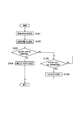
- FIG. 10 is a diagram showing a communication control method according to the fourth embodiment. In this operation, it is assumed that the UE 100 is in the RRC idle state or the RRC inactive state in the cell operated in the unlicensed band.
- step S401 the UE 100 evaluates the congestion degree by measuring the interference wave power for the high priority frequency.
- step S402 When it is evaluated that the high priority frequencies are mixed (step S402: YES), the UE 100 starts the timer and skips the measurement for the high priority frequencies in step S403. The UE 100 continues the measurement skip for the high priority frequency while the timer is operating.
- step S404 the UE 100 evaluates the congestion degree by measuring the interference wave power for the serving frequency.
- step S405 When it is evaluated that the serving frequencies are mixed (step S405: YES), the UE 100 stops the timer in step S406 and returns the process to step S401.
- step S407 the UE 100 confirms whether or not the timer has expired.
- step S407: YES the UE 100 returns the process to step S401.
- step S407: NO the UE 100 returns the process to step S404.
- the power consumption of the UE 100 can be saved by not measuring the adjacent frequency.
- FIG. 11 is a diagram showing a communication control method according to the fifth embodiment. In this operation, it is assumed that the UE 100 is in the RRC idle state or the RRC inactive state in the cell operated in the unlicensed band.
- the UE 100 evaluates the congestion degree by measuring the interference wave power in the unlicensed band in step S502 only when the predetermined condition is satisfied (step S501).
- the congestion degree evaluation basically assumes the congestion degree evaluation of the current serving cell (serving frequency), but may be applied to adjacent cells (adjacent frequencies).
- the UE 100 may evaluate the congestion degree of the adjacent cell (adjacent frequency) when the current serving cell (serving frequency) is congested.
- the priority set in the current serving cell (serving frequency) is not the highest priority or the highest rank (that is, the received power of the desired wave power is the highest)
- the UE 100 determines that the adjacent cell (adjacent frequency)
- the congestion degree may be evaluated. Such an operation may be similarly applied to each of the above-described embodiments.
- the predetermined condition for executing the congestion degree evaluation may be a condition that the reception power (desired wave power) of the radio signal received by the UE 100 from the serving cell is below a threshold value.
- This radio signal may be RLM-RS (Radio Link Monitoring Reference Signal) or SSB (Synchronization Signal and PBCH block).
- the UE 100 may consider that the gNB 200 has failed the LBT and may determine that the serving frequency is congested.
- the UE 100 may perform cell reselection to another cell of the same frequency. If the UE 100 determines that the serving frequency is congested, the UE 100 may perform inter frequency measurement and perform cell reselection to another cell of the adjacent frequency.
- the predetermined condition for executing the congestion degree evaluation is that the UE 100 performs a tracking area update process (TAU: Tracking Area Update) or a RAN notification area update process (RNAU: RAN-based Notification Area Update) via the cell.
- TAU is a process of notifying the AMF when the UE 100 moves from one tracking area to another tracking area.
- the RNAU is a process of notifying the destination gNB 200 when the UE 100 in the RRC connected state moves from one RAN-based Notification Area to another RAN-based Notification Area.
- the UE 100 may perform congestion degree evaluation on each of the serving frequency and the adjacent frequency, and may perform transmission on a frequency that is not crowded among these frequencies.
- the predetermined condition for executing the congestion degree evaluation may be a condition that the UE 100 performs a connection process for a cell.
- the connection process may be PRACH (Physical Random Access Channel) transmission in the random access procedure or Msg3 (eg, RRC Request message) transmission in the random access procedure.
- PRACH Physical Random Access Channel
- Msg3 eg, RRC Request message
- the UE 100 may perform congestion degree evaluation for each of the serving frequency and the adjacent frequency, and may perform transmission at a frequency that is not crowded among these frequencies.
- the predetermined condition for executing the congestion degree evaluation may be a condition that the UE 100 performs a cell reselection process.
- the UE 100 may perform inter frequency measurement when the serving frequency is congested.
- the 5G system (NR) has been mainly described, but the operation according to each of the embodiments may be applied to LTE.
- a program that causes a computer to execute each process performed by the UE 100 or the gNB 200 may be provided.
- the program may be recorded in a computer-readable medium.
- a computer readable medium can be used to install the program on a computer.
- the computer-readable medium in which the program is recorded may be a non-transitory recording medium.
- the non-transitory recording medium is not particularly limited, but may be a recording medium such as a CD-ROM or a DVD-ROM.
- a circuit that executes each process performed by the UE 100 or the gNB 200 may be integrated, and at least a part of the UE 100 or the gNB 200 may be configured as a semiconductor integrated circuit (chip set, SoC).
Landscapes
- Engineering & Computer Science (AREA)
- Computer Networks & Wireless Communication (AREA)
- Signal Processing (AREA)
- Computer Security & Cryptography (AREA)
- Mobile Radio Communication Systems (AREA)
Abstract
一実施形態に係る通信制御方法は、アンライセンスバンドで運用されるセルにおいて第1通信装置が第2通信装置との無線通信を行うための方法である。前記通信制御方法は、前記セルのキャリア周波数内において、第1帯域幅部分と、前記第1帯域幅部分よりも帯域幅が狭い第2帯域幅部分とを設定することと、前記第1通信装置が、前記第1帯域幅部分及び前記第2帯域幅部分について妨害波電力を測定することと、前記第1通信装置が、前記測定の結果に基づいて、妨害波が存在しないと評価した帯域幅部分を用いて前記第2通信装置に無線信号を送信することとを含む。
Description
本開示は、移動通信システムにおける通信制御方法に関する。
従来、3GPP(3rd Generation Partnership Project)のLTE(Long Term Evolution)において、免許が必要な周波数帯であるライセンスバンドと免許不要な周波数帯であるアンライセンスバンドとを併用してLTE通信を行うLAA(License-Assisted Access)が規定されている。なお、アンライセンスバンドは、Unlicensed spectrumと呼ばれることもある。
近年、第5世代(5G)の無線アクセス技術に位置付けられるNR(New Radio)の標準化が3GPPにおいて進められている。現状のNRの仕様には、アンライセンスバンドを用いる仕組みが規定されていないが、NR通信においてアンライセンスバンドを用いる技術であるNR-Uを導入するための議論が3GPPにおいて開始されている。
NR-Uにおいては、アンライセンスバンドをライセンスバンドと併用せずにアンライセンスバンドを単独で用いることが可能になると想定される。このような想定下においては、LAAには無い新たな機能が必要になると考えられる。
3GPP技術仕様書 「TS38.300 V15.3.0」 2018年9月、インターネット<URL: http://www.3gpp.org/ftp//Specs/archive/38_series/38.300/38300-f30.zip>
一実施形態に係る通信制御方法は、アンライセンスバンドで運用されるセルにおいて第1通信装置が第2通信装置との無線通信を行うための方法である。前記通信制御方法は、前記セルのキャリア周波数内において、第1帯域幅部分と、前記第1帯域幅部分よりも帯域幅が狭い第2帯域幅部分とを設定することと、前記第1通信装置が、前記第1帯域幅部分及び前記第2帯域幅部分について妨害波電力を測定することと、前記第1通信装置が、前記測定の結果に基づいて、妨害波が存在しないと評価した帯域幅部分を用いて前記第2通信装置に無線信号を送信することと、を含む。
一実施形態に係る通信制御方法は、アンライセンスバンドで運用されるセルにおいて用いられる方法である。前記通信制御方法は、前記セルに在圏する第1通信装置から第2通信装置に送信するデータが発生した場合、前記第1通信装置の物理レイヤが、前記アンライセンスバンドについて妨害波電力を測定することにより、妨害波が存在するか否かの評価を行うことと、前記第1通信装置から前記第2通信装置に送信するデータが発生していない場合であっても、前記第1通信装置の上位レイヤから前記物理レイヤに対する指示に応じて、前記物理レイヤが前記評価を行うことと、前記指示に応じて行われた前記評価の結果を前記物理レイヤから前記上位レイヤに通知することと、を含む。
一実施形態に係る通信制御方法は、アンライセンスバンドで運用されるセルにおいて、RRCコネクティッド状態にあるユーザ装置が、前記セルのキャリア周波数について妨害波電力を測定することにより前記セルについて混雑度を評価することと、前記ユーザ装置が、前記評価した混雑度に基づいて無線リンク障害を検知することと、前記無線リンク障害の検知に応じて、前記RRCコネクティッド状態を維持しつつ前記セルとは異なるセルを選択することにより、RRC再確立処理を行うことと、を含む。
一実施形態に係る通信制御方法は、アンライセンスバンドで運用されるセルにおいて、RRCアイドル状態又はRRCインアクティブ状態にあるユーザ装置が、前記セルのキャリア周波数に設定された優先度よりも高い優先度を有する高優先度周波数について妨害波電力を測定することにより、前記高優先度周波数について混雑度を評価することと、前記ユーザ装置が、前記高優先度周波数が混雑していると評価した場合、一定期間において前記高優先度周波数に対する測定をスキップすることと、を含む。
一実施形態に係る通信制御方法は、アンライセンスバンドで運用されるセルにおいて、RRCアイドル状態又はRRCインアクティブ状態にあるユーザ装置が、所定条件が満たされた場合に限り、前記アンライセンスバンドについて妨害波電力を測定することにより混雑度を評価することを含む。前記所定条件は、前記ユーザ装置が前記セルから受信する無線信号の受信電力が閾値を下回ったという条件、前記ユーザ装置が前記セルを介してトラッキングエリア更新処理又はRANノティフィケーションエリア更新処理を行うという条件、前記ユーザ装置が前記セルに対する接続処理を行うという条件、及び前記ユーザ装置が前記セルとは異なるセルの再選択処理を行うという条件、のうち少なくとも1つを含む。
一実施形態に係る通信制御方法は、アンライセンスバンドで運用されるセルにおいて、前記セルに在圏する第1通信装置から第2通信装置に送信するデータが発生した場合、前記第1通信装置が、前記データの送信を行う前にLBT(Listen Before Talk)を行うことと、前記第1通信装置が、前記LBTが失敗した回数を計測することと、前記第1通信装置が、前記LBTが失敗した回数に基づいて、前記第1通信装置と前記第2通信装置との間の無線リンク障害を検知することと、を含む
通信制御方法。
通信制御方法。
図面を参照しながら、実施形態に係る移動通信システムについて説明する。図面の記載において、同一又は類似の部分には同一又は類似の符号を付している。
(移動通信システム)
まず、一実施形態に係る移動通信システムの構成について説明する。一実施形態に係る移動通信システムは3GPPの5Gシステムであるが、移動通信システムには、LTEが少なくとも部分的に適用されてもよい。
まず、一実施形態に係る移動通信システムの構成について説明する。一実施形態に係る移動通信システムは3GPPの5Gシステムであるが、移動通信システムには、LTEが少なくとも部分的に適用されてもよい。
図1は、一実施形態に係る移動通信システムの構成を示す図である。
図1に示すように、移動通信システムは、ユーザ装置(UE:User Equipment)100と、5Gの無線アクセスネットワーク(NG-RAN:Next Generation Radio Access Network)10と、5Gのコアネットワーク(5GC:5G Core Network)20とを有する。
UE100は、移動可能な装置である。UE100は、ユーザにより利用される装置であればどのような装置であればよい。例えば、UE100は、携帯電話端末(スマートフォンを含む)、タブレット端末、ノートPC、通信モジュール(通信カード又はチップセットを含む)、センサ若しくはセンサに設けられる装置、車両若しくは車両に設けられる装置(Vehicle UE)、又は飛行体若しくは飛行体に設けられる装置(Aerial UE)である。
NG-RAN10は、基地局(5Gシステムにおいて「gNB」と呼ばれる)200を含む。gNB200は、NG-RANノードと呼ばれることもある。gNB200は、基地局間インターフェイスであるXnインターフェイスを介して相互に接続される。gNB200は、1又は複数のセルを管理する。gNB200は、自セルとの接続を確立したUE100との無線通信を行う。gNB200は、無線リソース管理(RRM)機能、ユーザデータ(以下、単に「データ」という)のルーティング機能、及び/又はモビリティ制御・スケジューリングのための測定制御機能等を有する。「セル」は、無線通信エリアの最小単位を示す用語として用いられる。「セル」は、UE100との無線通信を行う機能又はリソースを示す用語としても用いられる。1つのセルは1つのキャリア周波数に属する。
なお、gNBがLTEのコアネットワークであるEPC(Evolved Packet Core)に接続されてもよいし、LTEの基地局が5GCに接続されてもよい。また、LTEの基地局とgNBとが基地局間インターフェイスを介して接続されてもよい。
以下において、gNB200がUE100との無線通信を行う場合について主として説明するが、eNBがUE100との無線通信を行うことにより、eNBがサイドリンク通信を制御してもよい。
5GC20は、AMF(Access and Mobility Management Function)及びUPF(User Plane Function)300を含む。AMFは、UE100に対する各種モビリティ制御等を行う。AMFは、NAS(Non-Access Stratum)シグナリングを用いてUE100と通信することにより、UE100が在圏するエリアの情報を管理する。UPFは、データの転送制御を行う。AMF及びUPFは、基地局-コアネットワーク間インターフェイスであるNGインターフェイスを介してgNB200と接続される。
図2は、UE100(ユーザ装置)の構成を示す図である。
図2に示すように、UE100は、受信部110、送信部120、及び制御部130を備える。
受信部110は、制御部130の制御下で各種の受信を行う。受信部110は、アンテナ及び受信機を含む。受信機は、アンテナが受信する無線信号をベースバンド信号(受信信号)に変換して制御部130に出力する。
送信部120は、制御部130の制御下で各種の送信を行う。送信部120は、アンテナ及び送信機を含む。送信機は、制御部130が出力するベースバンド信号(送信信号)を無線信号に変換してアンテナから送信する。
制御部130は、UE100における各種の制御を行う。制御部130は、少なくとも1つのプロセッサと、プロセッサと電気的に接続された少なくとも1つのメモリを含む。メモリは、プロセッサにより実行されるプログラム、及びプロセッサによる処理に用いられる情報を記憶する。プロセッサは、ベースバンドプロセッサと、CPU(Central Processing Unit)と、を含んでもよい。ベースバンドプロセッサは、ベースバンド信号の変調・復調及び符号化・復号等を行う。CPUは、メモリに記憶されるプログラムを実行して各種の処理を行う。
図3は、gNB200(基地局)の構成を示す図である。
図3に示すように、gNB200は、送信部210、受信部220、制御部230、及びバックホール通信部240を備える。
送信部210は、制御部230の制御下で各種の送信を行う。送信部210は、アンテナ及び送信機を含む。送信機は、制御部230が出力するベースバンド信号(送信信号)を無線信号に変換してアンテナから送信する。
受信部220は、制御部230の制御下で各種の受信を行う。受信部220は、アンテナ及び受信機を含む。受信機は、アンテナが受信する無線信号をベースバンド信号(受信信号)に変換して制御部230に出力する。
制御部230は、gNB200における各種の制御を行う。制御部230は、少なくとも1つのプロセッサと、プロセッサと電気的に接続された少なくとも1つのメモリを含む。メモリは、プロセッサにより実行されるプログラム、及びプロセッサによる処理に用いられる情報を記憶する。プロセッサは、ベースバンドプロセッサと、CPUと、を含んでもよい。ベースバンドプロセッサは、ベースバンド信号の変調・復調及び符号化・復号等を行う。CPUは、メモリに記憶されるプログラムを実行して各種の処理を行う。
バックホール通信部240は、基地局間インターフェイスを介して隣接基地局と接続される。バックホール通信部240は、基地局-コアネットワーク間インターフェイスを介してAMF/UPF300と接続される。なお、gNBは、CU(Central Unit)とDU(Distributed Unit)とで構成され(すなわち、機能分割され)、両ユニット間がF1インターフェイスで接続されてもよい。
図4は、データを取り扱うユーザプレーンの無線インターフェイスのプロトコルスタックの構成を示す図である。
図4に示すように、ユーザプレーンの無線インターフェイスプロトコルは、物理(PHY)レイヤと、MAC(Medium Access Control)レイヤと、RLC(Radio Link Control)レイヤと、PDCP(Packet Data Convergence Protocol)レイヤと、SDAP(Service Data Adaptation Protocol)レイヤとを有する。
PHYレイヤは、符号化・復号、変調・復調、アンテナマッピング・デマッピング、及びリソースマッピング・デマッピングを行う。UE100のPHYレイヤとgNB200のPHYレイヤとの間では、物理チャネルを介してデータ及び制御情報が伝送される。
MACレイヤは、データの優先制御、ハイブリッドARQ(HARQ)による再送処理、及びランダムアクセスプロシージャ等を行う。UE100のMACレイヤとgNB200のMACレイヤとの間では、トランスポートチャネルを介してデータ及び制御情報が伝送される。gNB200のMACレイヤはスケジューラを含む。スケジューラは、上下リンクのトランスポートフォーマット(トランスポートブロックサイズ、変調・符号化方式(MCS))及びUE100への割当リソースブロックを決定する。
RLCレイヤは、MACレイヤ及びPHYレイヤの機能を利用してデータを受信側のRLCレイヤに伝送する。UE100のRLCレイヤとgNB200のRLCレイヤとの間では、論理チャネルを介してデータ及び制御情報が伝送される。
PDCPレイヤは、ヘッダ圧縮・伸張、及び暗号化・復号化を行う。
SDAPレイヤは、コアネットワークがQoS制御を行う単位であるIPフローとAS(Access Stratum)がQoS制御を行う単位である無線ベアラとのマッピングを行う。なお、RANがEPCに接続される場合は、SDAPが無くてもよい。
図5は、シグナリング(制御信号)を取り扱う制御プレーンの無線インターフェイスのプロトコルスタックの構成を示す図である。
図5に示すように、制御プレーンの無線インターフェイスのプロトコルスタックは、図4に示したSDAPレイヤに代えて、RRC(Radio Resource Control)レイヤ及びNAS(Non-Access Stratum)レイヤを有する。
UE100のRRCレイヤとgNB200のRRCレイヤとの間では、各種設定のためのRRCシグナリングが伝送される。RRCレイヤは、無線ベアラの確立、再確立及び解放に応じて、論理チャネル、トランスポートチャネル、及び物理チャネルを制御する。UE100のRRCとgNB200のRRCとの間に接続(RRC接続)がある場合、UE100はRRCコネクティッド状態にある。UE100のRRCとgNB200のRRCとの間に接続(RRC接続)がない場合、UE100はRRCアイドル状態にある。また、RRC接続が中断(サスペンド)されている場合、UE100はRRCインアクティブ状態にある。
RRCレイヤの上位に位置するNASレイヤは、セッション管理及びモビリティ管理等を行う。UE100のNASレイヤとAMF300のNASレイヤとの間では、NASシグナリングが伝送される。
なお、UE100は、無線インターフェイスのプロトコル以外にアプリケーションレイヤ等を有する。
(第1実施形態)
次に、上述した移動通信システムを前提として、第1実施形態について説明する。以下の各実施形態は、NR通信においてアンライセンスバンドを用いるNR-Uを前提とする。NR-Uは、アンライセンスバンドをライセンスバンドと併用せずにアンライセンスバンドを単独で用いるものであってもよい。
次に、上述した移動通信システムを前提として、第1実施形態について説明する。以下の各実施形態は、NR通信においてアンライセンスバンドを用いるNR-Uを前提とする。NR-Uは、アンライセンスバンドをライセンスバンドと併用せずにアンライセンスバンドを単独で用いるものであってもよい。
アンライセンスバンドは、無線LANなどの他のシステムからの妨害波(干渉波)が存在しうるとともに、移動通信システムの通信装置(UE100、gNB200)から他のシステムへ干渉を与えうる。このため、アンライセンスバンドにおいては、通信装置(UE100、gNB200)は、送信を行う前にLBT(Listen Before Talk)を適用することが義務づけられている。
LBTが適用される場合、UE100及びgNB200は、妨害波が存在するか否か、すなわち、チャネルが空いているか又は使用中(ビジー)であるかを評価するために、このチャネルの妨害波電力を測定及び監視する。
妨害波が存在しない、すなわち、チャネルが空いていると評価された場合、通信装置は、送信を実行することができる。一方、妨害波が存在する、すなわち、チャネルが使用中であると評価された場合、通信装置は、送信を実行することができない。通信装置は、妨害波が存在しないと評価される場合をLBT成功、妨害波が存在すると評価される場合をLBT失敗とみなす。このため、アンライセンスバンドにおいては通信装置が送信を行うことが可能な機会が制限される問題がある。
以下の第1実施形態において、上りリンクの通信を主として説明するが、第1実施形態は下りリンク又はサイドリンクにも適用可能である。サイドリンクとは、UE間の直接通信インターフェイスをいう。
第1実施形態に係る通信制御方法は、アンライセンスバンドで運用されるセルにおいて第1通信装置が第2通信装置との無線通信を行うための方法である。上りリンクの場合、第1通信装置はUE100であり、第2通信装置はgNB200である。下りリンクの場合、第1通信装置はgNB200であり、第2通信装置はUE100である。サイドリンクの場合、第1通信装置及び第2通信装置は互いに異なるUE100である。
第1実施形態において、セルのキャリア周波数内において、少なくとも、第1帯域幅部分と、第1帯域幅部分よりも帯域幅が狭い第2帯域幅部分とが設定される。第2帯域幅部分よりも帯域幅が狭い第2帯域幅部分がさらに設定されてもよい。
帯域幅部分とは、セルの全帯域の一部の周波数部分をいう。NRにおいて、このような帯域幅部分をBWP(Bandwidth part)と呼ばれる。BWPは、gNB200からUE100に設定され、一のBWPから他のBWPへの切り替えはgNB200により制御される。例えば、2つのBWPがUE100に設定されており、一方のBWPがアクティブ且つ他方のBWPが非アクティブである場合、gNB200は、アクティブなBWPを一方のBWPから他方のBWPに切替えるよう制御できる。また、BWPごとにサブキャリア間隔(subcarrier spacing)やサイクリックプリフィックスを可変設定できる。
BWP間の切り替えは、PDCCH(Physical Downlink Control Channel)上で送信されるDCI(Downlink Control Information)又は非活性化タイマによって行われる。サービングセルに非アクティブタイマが設定されている場合、そのセルに関連付けられている非アクティブタイマが満了すると、アクティブなBWPはネットワークから設定されているデフォルトのBWPに切り替わる。
図6は、UE100に設定されるBWPの一例を示す図である。図6において、上りリンク用に4つのBWPが設定される一例を示している。
図6に示すように、4つのBWPは、帯域幅が最も広いBWP#1と、帯域幅が2番目に広いBWP#2と、帯域幅が3番目に広いBWP#3と、帯域幅が最も狭いBWP#4とを含む。gNB200は、周波数方向においてBWPが重複するように設定する。
なお、図6において、各BWPが、最も狭いBWP#4の帯域幅の整数倍の帯域幅を有する一例を示しているが、各BWPの帯域幅は最も狭いBWPの整数倍でなくてもよい。また、各BWPのサブキャリア間隔は同じであってもよいし、異なっていてもよい。複数のBWPのうち、少なくとも一つのBWPが他のBWPと周波数方向で重複しなくともよい。複数のBWPの各々は、周波数方向で互いに重複しなくともよい。
図7は、第1実施形態に係る通信制御方法を示す図である。図7に示す動作において、UE100がRRCコネクティッド状態にあると仮定している。
図7に示すように、ステップS101において、図6に示すような複数のBWPがgNB200からUE100に設定される。BWPは、ブロードキャストのRRCシグナリングであるSIB(System Information Block)により設定されてもよいし、ユニキャストRRCシグナリング(以下、専用RRCシグナリングと呼ぶ)により設定されてもよい。
また、gNB200は、設定した複数のBWPをアクティブにする。例えば、gNB200は、設定した複数のBWPをアクティブにするDCIをUE100に送信してもよいし、各BWPの非アクティブタイマを同時に動作させてもよい。その後、gNB200は、各BWPについてUE100からの上りリンク送信を監視する(すなわち、復号を試みる)。上りリンク送信は、PUSCH(Physical Uplink Shared Channel)送信、PUCCH(Physical Uplink Control Channel)送信、及び/又は他の上りリンクチャネルの送信であってもよい。
ステップS102において、UE100は、設定され且つアクティブなBWPについて妨害波電力を測定する。ここで、UE100は、最も広いBWPについて所定の周波数単位ごとに妨害波電力を測定する。所定の周波数単位とは、最も狭いBWPの帯域幅、リソースブロックの帯域幅、又はサブキャリアの帯域幅をいう。なお、リソースブロックは、複数のサブキャリアにより構成される。
例えば、図6において、UE100は、BWP#1の帯域内において、BWP#4の帯域幅ごとに妨害波電力を測定する。具体的には、図6に示すF1乃至F4の各帯域について妨害波電力を測定する。そして、UE100は、F1乃至F4の妨害波電力を積算することでBWP#1の測定結果を取得し、F1乃至F3の妨害波電力を積算することでBWP#2の測定結果を取得する。さらに、F1及びF2の妨害波電力を積算することでBWP#3の測定結果を取得し、F1の妨害波電力をそのままBWP#4の測定結果として取得する。これにより、1つのBWPについて妨害波電力を測定するだけで、4つのBWPについての測定結果を効率的に得ることができる。なお、リソースブロック単位又はサブキャリア単位で測定を行う場合も、同様の方法で各BWPの測定結果を得ることができる。
ステップS103において、UE100は、最も広いBWP#1について得られた測定結果に基づいて、BWP#1に妨害波が存在するか否かを評価する。例えば、UE100は、BWP#1について得られた測定結果を、gNB200から設定された閾値と比較し、測定結果が閾値未満であれば妨害波が存在しない(すなわち、LBT成功)と評価する。この場合、BWP#1を利用可能である。これに対し、測定結果が閾値以上であれば妨害波が存在する(すなわち、LBT失敗)と評価する。この場合、BWP#1を利用不可である。
BWP#1に妨害波が存在しないと評価した場合(ステップS103:YES)、ステップS104において、UE100は、BWP#1を用いてgNB200に対する上りリンク送信を行う。
一方、BWP#1に妨害波が存在すると評価した場合(ステップS103:NO)、ステップS105において、UE100は、次に広いBWP#2について得られた測定結果に基づいて、BWP#2に妨害波が存在するか否かを評価する。
BWP#2に妨害波が存在しないと評価した場合(ステップS105:YES)、ステップS106において、UE100は、BWP#2を用いてgNB200に対する上りリンク送信を行う。
一方、BWP#2に妨害波が存在すると評価した場合(ステップS105:NO)、再びステップS105において、UE100は、次に広いBWP#3について得られた測定結果に基づいて、BWP#3に妨害波が存在するか否かを評価する。
このように、利用可能なBWPが見つかるまで処理を繰り返す。但し、UE100は、最も狭いBWP#4まで処理を繰り返し、BWP#4についてLBT失敗と評価した場合、一定時間の経過後に本フローを最初からやり直す。
第1実施形態によれば、特に妨害波が狭帯域信号であるという想定下において、広帯域LBTで失敗した場合であっても、狭帯域LBTで評価すると成功する可能性があるため、LBT成功率を上げることができる。
(第1実施形態の変更例)
上述した第1実施形態において、UE100が広いBWPから狭いBWPへの順にLBTの評価を行う一例について説明した。
上述した第1実施形態において、UE100が広いBWPから狭いBWPへの順にLBTの評価を行う一例について説明した。
しかしながら、評価する順番は、gNB200の設定によりUE100に指定されてもよい。例えば、gNB200は、LBTの評価を行う優先順位を専用RRCシグナリングによりUE100に設定する。UE100は、gNB200から設定された優先順位に応じて、BWPごとにLBTの評価を行う。
これによって、例えば、gNB200がUE100毎に別々のBWP優先度を設定し、UE100が送信に用いるBWPを分散させることが期待できる。これにより、システム全体としてLBT失敗の確率を下げることができる。
上述したように、複数のBWPのうち、少なくとも一つのBWPが他のBWPと周波数方向で重複しなくともよい。換言すれば、複数のBWPのうち、少なくとも一つのBWPが他のBWPと周波数方向で離間していてもよい。複数のBWPの各々は、周波数方向で互いに離間していてもよい。
この場合、UE100が、周波数方向で重複する複数のBWPにおいてLBT失敗と評価されたとしても、周波数方向で離間するBWPでLBTが成功する可能性がある。つまり、図6に示す帯域F1に妨害波が存在すると図7に示す動作フローで一定時間経過後にフローを最初からやり直す必要が生じるが、そのような可能性を減らすことができる。その結果、LBT失敗の確率を下げることができる。
(第2実施形態)
第2実施形態について、上述した第1実施形態との相違点を主として説明する。
第2実施形態について、上述した第1実施形態との相違点を主として説明する。
上述したように、アンライセンスバンドにおいて、妨害波が存在するか否かの評価(以下、「LBTチェック」と呼ぶ)は、送信データが発生した場合に実行される。具体的には、アンライセンスバンドで運用されるセルに在圏する第1通信装置から第2通信装置に送信するデータが発生した場合、第1通信装置の物理レイヤが、アンライセンスバンドについて妨害波電力を測定することによりLBTチェックを行う(第1実施形態を参照)。
NR-Uにおいて、RRCアイドル状態又はRRCインアクティブ状態にあるUE100は、セル再選択処理により、アンライセンスバンドで運用されるセルをサービングセルとして選択しうる。ここで、UE100は、妨害波が存在しないようなセルをセル再選択処理において再選択することが望ましい。なお、RRCアイドル状態又はRRCインアクティブ状態においてUE100のサービングセルは、UE100が「キャンプするセル」と呼ばれることもある。
しかしながら、一般的なセル再選択処理は、UE100が、サービングセルからの参照信号の受信電力と、1又は複数の隣接セルからの参照信号の受信電力を測定し、最も受信電力が高くなるセル(ベストセル)を自身のサービングセルとして再選択することを基本としている。所望波の受信状態が最も良好になるセルであっても、妨害波が存在する場合には、そのセルを再選択することは好ましくない。
よって、NR-Uにおいては、送信データが発生していない場合であってもLBTチェックを実施できることが望まれる。
図8は、第2実施形態に係る通信制御方法を示す図である。ここでは、UE100の動作を例に挙げて説明するが、図8の動作をgNB200が行ってもよい。なお、UE100はアンライセンスバンドで運用されるセルにおいてRRCアイドル状態又はRRCインアクティブ状態にあると仮定しているが、UE100がRRCコネクティッド状態であってもよい。
図8に示すように、ステップS201において、UE100の上位レイヤは、UE100(第1通信装置)から他の通信装置(第2通信装置)に送信するデータが発生していない場合であっても、UE100の物理レイヤに対してLBTチェックを行うように指示する。この指示を行うトリガの具体例については、第5実施形態において説明する。
ここで、上位レイヤは、MACレイヤ、又はRRCレイヤであってもよい。
例えば、上位レイヤは、LBTチェックを行うように指示するLBT check indicationを物理レイヤに通知する。上位レイヤは、物理レイヤがLBT checkを何回実施すべきか(例えば、N回(N≧1))を物理レイヤに通知してもよい。
また、上位レイヤは、LBTチェック対象のキャリア周波数又はチャネルを物理レイヤに通知してもよい。LBTチェック対象は、サービングセルのキャリア周波数であるサービング周波数、サービング周波数の一部の帯域(チャネル)、サービング周波数とは異なる隣接周波数(具体的には、アンライセンスバンドに属する隣接周波数)、及び/又は隣接周波数の一部の帯域(チャネル)であってもよい。
ステップS202において、UE100の物理レイヤは、上位レイヤからの指示に応じてLBTチェックを行う。物理レイヤは、上位レイヤから通知された回数のLBTチェックを行ってもよい。
ステップS203において、UE100の物理レイヤは、ステップS202のLBTチェックの結果を上位レイヤに通知する。例えば、物理レイヤは、LBT成功又はLBT失敗を上位レイヤに通知する。物理レイヤは、複数回のLBT check結果を上位レイヤに通知してもよい(例えば、M回成功、L回失敗(M,L≧0))。物理レイヤは、LBT checkを実行した回数と、成功した回数とを上位レイヤに通知し、失敗した回数を上位レイヤに通知しなくともよい。物理レイヤは、LBT checkを実行した回数と、失敗した回数とを上位レイヤに通知し、成功した回数を上位レイヤに通知しなくともよい。
ステップS204において、UE100の上位レイヤは、物理レイヤからの通知に基づいて、アンライセンスバンドについて混雑度を判定(評価)する。例えば、上位レイヤは、LBTチェック失敗の場合、LBTチェックがN回(N≧2)以上失敗した場合、LBTチェックが失敗した割合が閾値以上である場合、LBTチェック対象のキャリア周波数又はチャネルが混雑していると判定してもよい。
第2実施形態によれば、物理レイヤと上位レイヤとの間のレイヤ間の協調により、送信データが発生していない場合であってもLBTチェックを実施可能とすることができる。
(第3実施形態)
第3実施形態について、上述した各実施形態との相違点を主として説明する。第3実施形態は、無線リンク障害(RLF)に関する実施形態である。
第3実施形態について、上述した各実施形態との相違点を主として説明する。第3実施形態は、無線リンク障害(RLF)に関する実施形態である。
一般的に、RRCコネクティッド状態にあるUE100は、物理レイヤにおいて無線問題が検知されてから一定時間内にこの無線問題が回復しない場合、ランダムアクセス手順が失敗した場合、又はRLCレイヤの障害が検知された場合、RLFを検知する。ここで物理レイヤの無線問題は、例えば、サービングセルからの同期信号の受信不良により同期外れ(out of sync)が発生したことである。
そして、RLFを検知したUE100は、RRCコネクティッド状態を維持しつつ、他の適切なセルを選択してRRC再確立を開始する。但し、RLFが検知されてから一定時間内に適切なセルが見つからなかった場合は、UE100は、RRCアイドル状態に遷移する。
しかしながら、NR-Uにおいては、上述したような一般的なRLFの検知基準に加えて、妨害波の状況を加味したRLF検知基準が導入されることが望ましい。
図9は、第3実施形態に係る通信制御方法を示す図である。本動作において、UE100はアンライセンスバンドで運用されるセルにおいてRRCコネクティッド状態にあると仮定している。
図9に示すように、ステップS301において、UE100は、サービングセルのキャリア周波数について妨害波電力を測定することにより、サービングセルについて混雑度を評価する。
ここで、混雑度の評価方法は、上述した第1実施形態及び第2実施形態と同様であってもよい。混雑度の評価方法は、チャネル占有率(Channel occupancy)に基づくものであってもよい。チャネル占有率とは、ある一定期間において測定された複数の受信電力(RSSI:Received Signal Strength Indicator)サンプル値のうち閾値を超えるRSSIサンプル値の割合をいう。この一定期間及び閾値は、gNB200からUE100に設定されてもよい。また、gNB200は、RSSI測定を行うべきタイミングをUE100に設定してもよい。例えば、gNB200は、自身が無線信号を送信しないタイミングにおいてUE100がRSSI測定を行うようにRSSI測定タイミングを決定する。gNB200は、当該決定したRSSI測定タイミングを専用RRCシグナリングによりUE100に設定してもよい。
ステップS302において、UE100は、ステップS302で評価した混雑度に基づいて、RLFを検知する。例えば、UE100は、LBTチェック失敗の場合、LBTチェックがN回(N≧2)以上失敗した場合、LBTチェックが失敗した割合が閾値以上である場合、又はチャネル占有率が閾値以上である場合、サービングセルが混雑していると判定し、RLFを検知してもよい。
ここで、UE100は、上述した一般的なRLF検知基準が満たされていない場合であっても、サービングセルが混雑していると判定した場合には、RLFを検知してもよい。例えば、UE100は、物理レイヤにおいて無線問題が検知されていない(例えば、サービングセルからの同期信号を正常に受信できている)場合であっても、サービングセルが混雑していると判定した場合には、RLFを検知してもよい。
ステップS303において、UE100は、RLFの検知に応じて、RRCコネクティッド状態を維持しつつ現在のサービングセルとは異なるセルを選択することにより、RRC再確立処理を行う。
第3実施形態によれば、NR-Uに適したRLF検知基準を導入し、サービングセルが混雑しているような場合にUE100が他のセルに移行できる。
なお、NR-UにおいてDual Connectivityが適用される場合、SCG(Secondary Cell Group)-RLFに同様の検知基準を適用してもよい。Dual Connectivityは、UE100がマスタ基地局及びセカンダリ基地局と同時に通信する技術であり、SCGは、セカンダリ基地局により管理されるセカンダリセルからなるグループである。この場合、上述した第3実施形態におけるサービングセルをセカンダリセルと読み替えればよい。
また、SCG-RLFを検知したUE100は、SCG-RLFに関する情報(SCG failure information)をマスタ基地局に送信してもよい。ここで、UE100は、障害の種別(failure type)として、混雑によるfailure(channel occupied等)を示す情報をSCG failure informationに含めてもよい。
(第4実施形態)
第4実施形態について、上述した各実施形態との相違点を主として説明する。第4実施形態は、RRCアイドル状態又はRRCインアクティブ状態におけるセル再選択処理に関する実施形態である。
第4実施形態について、上述した各実施形態との相違点を主として説明する。第4実施形態は、RRCアイドル状態又はRRCインアクティブ状態におけるセル再選択処理に関する実施形態である。
一般的なセル再選択処理においては、gNB200からUE100に周波数優先度が設定され、UE100は周波数優先度を考慮してセル再選択処理を行う。例えば、UE100は、現在のサービングセルのキャリア周波数に設定された優先度よりも高い優先度を有する隣接周波数が存在する場合、この隣接周波数に対する測定(所望波の受信電力の測定)を常に行う。このような測定は、インター周波数測定と呼ばれる。
しかしながら、NR-Uにおいて、高優先度の隣接周波数が混雑している場合には、この隣接周波数に属するセルを再選択することは好ましくないため、この隣接周波数に対する測定を行わないことが望ましい。これにより、測定によるUE100の消費電力を節約できる。
第4実施形態において、RRCアイドル状態又はRRCインアクティブ状態にあるUE100は、現在のサービングセルのキャリア周波数に設定された優先度よりも高い優先度を有する高優先度周波数について妨害波電力を測定する。これにより、当該UE100は、高優先度周波数について混雑度を評価する。混雑度の評価方法については、上述した第1実施形態乃至第3実施形態と同様である。
そして、UE100は、高優先度周波数が混雑していると評価した場合、一定期間において高優先度周波数に対する測定をスキップする。ここで、この一定期間を規定するタイマの値は、gNB200からUE100にSIB又は専用RRCシグナリングにより設定されてもよい。
例えば、UE100は、高優先度周波数が混雑していると評価した場合、一定期間において、混雑度評価(すなわち、妨害波電力の測定)をスキップしてもよいし、この高優先度周波数に対するインター周波数測定(すなわち、所望波電力の測定)をスキップしてもよい。
UE100は、高優先度周波数が混雑していると評価した場合、一定期間において、この高優先度周波数に設定された優先度を下げる(例えば、最低優先度とみなす)ことにより測定を抑制してもよい。
図10は、第4実施形態に係る通信制御方法を示す図である。本動作において、UE100はアンライセンスバンドで運用されるセルにおいてRRCアイドル状態又はRRCインアクティブ状態にあると仮定している。
図10に示すように、ステップS401において、UE100は、高優先度周波数について妨害波電力を測定することにより混雑度を評価する。
高優先度周波数が混在していると評価した場合(ステップS402:YES)、ステップS403において、UE100は、タイマをスタートするとともに、高優先度周波数に対する測定をスキップする。UE100は、タイマが動作している間は、高優先度周波数に対する測定スキップを継続する。
ステップS404において、UE100は、サービング周波数について妨害波電力を測定することにより混雑度を評価する。
サービング周波数が混在していると評価した場合(ステップS405:YES)、ステップS406において、UE100は、タイマを停止し、ステップS401に処理を戻す。
一方、サービング周波数が混在していないと評価した場合(ステップS405:NO)、ステップS407において、UE100は、タイマが満了したか否かを確認する。タイマが満了した場合(ステップS407:YES)、UE100は、ステップS401に処理を戻す。タイマが満了していない場合(ステップS407:NO)、UE100は、ステップS404に処理を戻す。
第4実施形態によれば、高優先度の隣接周波数が混雑している場合に、この隣接周波数に対する測定を行わないことにより、UE100の消費電力を節約できる。
(第5実施形態)
第5実施形態について、上述した各実施形態との相違点を主として説明する。
第5実施形態について、上述した各実施形態との相違点を主として説明する。
上述した混雑度評価(特に、チャネル占有率の測定)は、UE100の消費電力が大きいため、できる限り混雑度評価を行う時間及び回数を削減することが望ましい。
図11は、第5実施形態に係る通信制御方法を示す図である。本動作において、UE100はアンライセンスバンドで運用されるセルにおいてRRCアイドル状態又はRRCインアクティブ状態にあると仮定している。
図11に示すように、UE100は、所定条件が満たされた場合(ステップS501)に限り、ステップS502において、アンライセンスバンドについて妨害波電力を測定することにより混雑度を評価する。
ここで、混雑度評価は、基本的には現在のサービングセル(サービング周波数)の混雑度評価を想定しているが、隣接セル(隣接周波数)に対して適用されてもよい。例えば、UE100は、現在のサービングセル(サービング周波数)が混雑していた場合に、隣接セル(隣接周波数)の混雑度評価を行ってもよい。UE100は、現在のサービングセル(サービング周波数)に設定された優先度が最高優先度ではない又は最上ランク(すなわち、所望波電力の受信電力が最も高い)ではない場合に、隣接セル(隣接周波数)の混雑度評価を行ってもよい。このような動作は、上述した各実施形態においても同様に適用してもよい。
混雑度評価を実行するべき所定条件は、UE100がサービングセルから受信する無線信号の受信電力(所望波電力)が閾値を下回ったという条件であってもよい。この無線信号は、RLM-RS(Radio Link Monitoring Reference Signal)であってもよいし、SSB(Synchronization Signal and PBCH block)であってもよい。所望波電力がゼロである場合、UE100は、gNB200がLBTに失敗したとみなし、サービング周波数が混雑していると判定してもよい。UE100は、サービング周波数が混雑していないと判定した場合、同一周波数の他セルへのセル再選択を行ってもよい。UE100は、サービング周波数が混雑していると判定した場合、インター周波数測定を行い、隣接周波数の他セルへのセル再選択を行ってもよい。
混雑度評価を実行するべき所定条件は、UE100がセルを介してトラッキングエリア更新処理(TAU:Tracking Area Update)又はRANノティフィケーションエリア更新処理(RNAU:RAN-based Notification Area Update)を行うという条件であってもよい。TAUは、UE100が一のトラッキングエリアから他のトラッキングエリアに移動する際にAMFに対して通知する処理である。RNAUは、RRCコネクティッド状態にあるUE100が一のRAN-based Notification Areaから他のRAN-based Notification Areaに移動する際に移動先のgNB200に対して通知する処理である。ここで、UE100は、サービング周波数及び隣接周波数のそれぞれについて混雑度評価を行い、これらの周波数のうち混雑していない周波数において送信を行ってもよい。
混雑度評価を実行するべき所定条件は、UE100がセルに対する接続処理を行うという条件であってもよい。接続処理は、ランダムアクセスプロシージャにおけるPRACH(Physical Random Access Channel)送信であってもよいし、ランダムアクセスプロシージャにおけるMsg3(例えば、RRC Requestメッセージ)送信であってもよい。ここで、UE100は、サービング周波数及び隣接周波数のそれぞれについて混雑度評価を行い、これらの周波数のうち混雑していない周波数において送信を行ってもよい。
混雑度評価を実行するべき所定条件は、UE100がセル再選択処理を行うという条件であってもよい。ここで、UE100は、サービング周波数が混雑している場合、インター周波数測定を行ってもよい。
(その他の実施形態)
上述した各実施形態は、別個独立して実施するだけではなく、2以上の実施形態を組み合わせて実施してもよい。
上述した各実施形態は、別個独立して実施するだけではなく、2以上の実施形態を組み合わせて実施してもよい。
上述した各実施形態において、5Gシステム(NR)について主として説明したが、各実施形態に係る動作をLTEに適用してもよい。
なお、UE100又はgNB200が行う各処理をコンピュータに実行させるプログラムが提供されてもよい。プログラムは、コンピュータ読取り可能媒体に記録されていてもよい。コンピュータ読取り可能媒体を用いれば、コンピュータにプログラムをインストールすることが可能である。ここで、プログラムが記録されたコンピュータ読取り可能媒体は、非一過性の記録媒体であってもよい。非一過性の記録媒体は、特に限定されるものではないが、例えば、CD-ROMやDVD-ROM等の記録媒体であってもよい。
また、UE100又はgNB200が行う各処理を実行する回路を集積化し、UE100又はgNB200の少なくとも一部を半導体集積回路(チップセット、SoC)として構成してもよい。
以上、図面を参照して一実施形態について詳しく説明したが、具体的な構成は上述のものに限られることはなく、要旨を逸脱しない範囲内において様々な設計変更等をすることが可能である。
本願は、米国仮出願第62/790592号(2019年1月10日出願)の優先権を主張し、その内容の全てが本願明細書に組み込まれている。
Claims (11)
- アンライセンスバンドで運用されるセルにおいて第1通信装置が第2通信装置との無線通信を行うための通信制御方法であって、
前記セルのキャリア周波数内において、第1帯域幅部分と、前記第1帯域幅部分よりも帯域幅が狭い第2帯域幅部分とを設定することと、
前記第1通信装置が、前記第1帯域幅部分及び前記第2帯域幅部分について妨害波電力を測定することと、
前記第1通信装置が、前記測定の結果に基づいて、妨害波が存在しないと評価した帯域幅部分を用いて前記第2通信装置に無線信号を送信することと、を含む
通信制御方法。 - 前記第1通信装置が、前記測定の結果に基づいて、前記第1帯域幅部分に妨害波が存在すると評価した場合、前記第2帯域幅部分に妨害波が存在するか否かを評価することをさらに含み、
前記送信することは、前記第1通信装置が、前記第2帯域幅部分に妨害波が存在しないと評価した場合、前記第2帯域幅部分を用いて前記第2通信装置に無線信号を送信することを含む
請求項1に記載の通信制御方法。 - 前記設定することは、周波数方向において前記第2帯域幅部分を前記第1帯域幅部分と重複させて設定することを含み、
前記測定することは、前記第1帯域幅部分について所定の周波数単位ごとに妨害波電力を測定することにより、前記第1帯域幅部分の測定結果だけではなく前記第2帯域幅部分の測定結果も取得することを含む
請求項1又は2に記載の通信制御方法。 - 前記第1通信装置はユーザ装置であり、前記第2通信装置は基地局である
請求項1乃至3のいずれか1項に記載の通信制御方法。 - アンライセンスバンドで運用されるセルにおいて用いられる通信制御方法であって、
前記セルに在圏する第1通信装置から第2通信装置に送信するデータが発生した場合、前記第1通信装置の物理レイヤが、前記アンライセンスバンドについて妨害波電力を測定することにより、妨害波が存在するか否かの評価を行うことと、
前記第1通信装置から前記第2通信装置に送信するデータが発生していない場合であっても、前記第1通信装置の上位レイヤから前記物理レイヤに対する指示に応じて、前記物理レイヤが前記評価を行うことと、
前記指示に応じて行われた前記評価の結果を前記物理レイヤから前記上位レイヤに通知することと、を含む
通信制御方法。 - 前記上位レイヤが、前記物理レイヤからの前記通知に基づいて、前記アンライセンスバンドについて混雑度を判定することをさらに含む
請求項5に記載の通信制御方法。 - 前記上位レイヤは、MAC(Medium Access Control)レイヤである
請求項5又は6に記載の通信制御方法。 - アンライセンスバンドで運用されるセルにおいて、RRC(Radio Resource Control)コネクティッド状態にあるユーザ装置が、前記セルのキャリア周波数について妨害波電力を測定することにより前記セルについて混雑度を評価することと、
前記ユーザ装置が、前記評価した混雑度に基づいて無線リンク障害を検知することと、
前記無線リンク障害の検知に応じて、前記RRCコネクティッド状態を維持しつつ前記セルとは異なるセルを選択することにより、RRC再確立処理を行うことと、を含む
通信制御方法。 - アンライセンスバンドで運用されるセルにおいて、RRC(Radio Resource Control)アイドル状態又はRRCインアクティブ状態にあるユーザ装置が、前記セルのキャリア周波数に設定された優先度よりも高い優先度を有する高優先度周波数について妨害波電力を測定することにより、前記高優先度周波数について混雑度を評価することと、
前記ユーザ装置が、前記高優先度周波数が混雑していると評価した場合、一定期間において前記高優先度周波数に対する測定をスキップすることと、を含む
通信制御方法。 - アンライセンスバンドで運用されるセルにおいて、RRC(Radio Resource Control)アイドル状態又はRRCインアクティブ状態にあるユーザ装置が、所定条件が満たされた場合に限り、前記アンライセンスバンドについて妨害波電力を測定することにより混雑度を評価することを含み、
前記所定条件は、
前記ユーザ装置が前記セルから受信する無線信号の受信電力が閾値を下回ったという条件、
前記ユーザ装置が前記セルを介してトラッキングエリア更新処理又はRAN(Radio Access Network)ノティフィケーションエリア更新処理を行うという条件、
前記ユーザ装置が前記セルに対する接続処理を行うという条件、及び
前記ユーザ装置が前記セルとは異なるセルの再選択処理を行うという条件、のうち少なくとも1つを含む
通信制御方法。 - アンライセンスバンドで運用されるセルにおいて用いられる通信制御方法であって、
前記セルに在圏する第1通信装置から第2通信装置に送信するデータが発生した場合、前記第1通信装置が、前記データの送信を行う前にLBT(Listen Before Talk)を行うことと、
前記第1通信装置が、前記LBTが失敗した回数を計測することと、
前記第1通信装置が、前記LBTが失敗した回数に基づいて、前記第1通信装置と前記第2通信装置との間の無線リンク障害を検知することと、を含む
通信制御方法。
Priority Applications (4)
| Application Number | Priority Date | Filing Date | Title |
|---|---|---|---|
| JP2020565634A JP7270649B2 (ja) | 2019-01-10 | 2019-12-10 | 通信制御方法 |
| US17/371,625 US11985701B2 (en) | 2019-01-10 | 2021-07-09 | Communication control method |
| JP2022083583A JP7442571B2 (ja) | 2019-01-10 | 2022-05-23 | 通信制御方法 |
| US18/630,698 US12356450B2 (en) | 2019-01-10 | 2024-04-09 | Communication control method |
Applications Claiming Priority (2)
| Application Number | Priority Date | Filing Date | Title |
|---|---|---|---|
| US201962790592P | 2019-01-10 | 2019-01-10 | |
| US62/790,592 | 2019-01-10 |
Related Child Applications (1)
| Application Number | Title | Priority Date | Filing Date |
|---|---|---|---|
| US17/371,625 Continuation US11985701B2 (en) | 2019-01-10 | 2021-07-09 | Communication control method |
Publications (1)
| Publication Number | Publication Date |
|---|---|
| WO2020145000A1 true WO2020145000A1 (ja) | 2020-07-16 |
Family
ID=71520153
Family Applications (1)
| Application Number | Title | Priority Date | Filing Date |
|---|---|---|---|
| PCT/JP2019/048235 Ceased WO2020145000A1 (ja) | 2019-01-10 | 2019-12-10 | 通信制御方法 |
Country Status (3)
| Country | Link |
|---|---|
| US (2) | US11985701B2 (ja) |
| JP (2) | JP7270649B2 (ja) |
| WO (1) | WO2020145000A1 (ja) |
Cited By (2)
| Publication number | Priority date | Publication date | Assignee | Title |
|---|---|---|---|---|
| JPWO2022024945A1 (ja) * | 2020-07-28 | 2022-02-03 | ||
| US20230073817A1 (en) * | 2021-09-07 | 2023-03-09 | Qualcomm Incorporated | Jammer detection system |
Families Citing this family (3)
| Publication number | Priority date | Publication date | Assignee | Title |
|---|---|---|---|---|
| WO2020159287A1 (en) * | 2019-02-01 | 2020-08-06 | Lg Electronics Inc. | Method and apparatus for handling bearers based on congestion level in a wireless communication system |
| WO2020159307A1 (en) * | 2019-02-01 | 2020-08-06 | Lg Electronics Inc. | Method and apparatus for handling packet duplication based on congestion level of frequency in a wireless communication system |
| CN111615146B (zh) * | 2019-06-28 | 2023-01-10 | 维沃移动通信有限公司 | 处理方法及设备 |
Citations (5)
| Publication number | Priority date | Publication date | Assignee | Title |
|---|---|---|---|---|
| WO2016121672A1 (ja) * | 2015-01-30 | 2016-08-04 | 京セラ株式会社 | ユーザ端末及び基地局 |
| WO2017081800A1 (ja) * | 2015-11-12 | 2017-05-18 | 富士通株式会社 | 端末装置、基地局装置、無線通信システム及び無線通信方法 |
| JP2018113674A (ja) * | 2017-01-13 | 2018-07-19 | パナソニック インテレクチュアル プロパティ コーポレーション オブ アメリカPanasonic Intellectual Property Corporation of America | 無線通信装置及び無線通信方法 |
| JP2018535566A (ja) * | 2015-10-23 | 2018-11-29 | グァンドン オッポ モバイル テレコミュニケーションズ コーポレーション リミテッド | 滞留セルの選択方法及び装置 |
| US20180352537A1 (en) * | 2017-05-30 | 2018-12-06 | Huawei Technologies Co., Ltd. | Grant-based uplink transmission in unlicensed band |
Family Cites Families (5)
| Publication number | Priority date | Publication date | Assignee | Title |
|---|---|---|---|---|
| WO2015115573A1 (ja) | 2014-01-31 | 2015-08-06 | 京セラ株式会社 | 通信制御方法 |
| CN109076373B (zh) * | 2016-04-11 | 2022-04-12 | 瑞典爱立信有限公司 | 基于lbt参数控制测量的方法 |
| US20190097765A1 (en) * | 2017-09-25 | 2019-03-28 | Mediatek Singapore Pte. Ltd. | Method And Apparatus For Detecting Poor Channel Conditions In Uplink Grant-Free Transmission |
| US10925093B2 (en) * | 2018-11-13 | 2021-02-16 | Mediatek Singapore Pte. Ltd. | Method and apparatus for detecting consistent listen before talk failure in mobile communications |
| US20200221309A1 (en) * | 2019-01-07 | 2020-07-09 | Qualcomm Incorporated | Handling of channel access problems |
-
2019
- 2019-12-10 JP JP2020565634A patent/JP7270649B2/ja active Active
- 2019-12-10 WO PCT/JP2019/048235 patent/WO2020145000A1/ja not_active Ceased
-
2021
- 2021-07-09 US US17/371,625 patent/US11985701B2/en active Active
-
2022
- 2022-05-23 JP JP2022083583A patent/JP7442571B2/ja active Active
-
2024
- 2024-04-09 US US18/630,698 patent/US12356450B2/en active Active
Patent Citations (5)
| Publication number | Priority date | Publication date | Assignee | Title |
|---|---|---|---|---|
| WO2016121672A1 (ja) * | 2015-01-30 | 2016-08-04 | 京セラ株式会社 | ユーザ端末及び基地局 |
| JP2018535566A (ja) * | 2015-10-23 | 2018-11-29 | グァンドン オッポ モバイル テレコミュニケーションズ コーポレーション リミテッド | 滞留セルの選択方法及び装置 |
| WO2017081800A1 (ja) * | 2015-11-12 | 2017-05-18 | 富士通株式会社 | 端末装置、基地局装置、無線通信システム及び無線通信方法 |
| JP2018113674A (ja) * | 2017-01-13 | 2018-07-19 | パナソニック インテレクチュアル プロパティ コーポレーション オブ アメリカPanasonic Intellectual Property Corporation of America | 無線通信装置及び無線通信方法 |
| US20180352537A1 (en) * | 2017-05-30 | 2018-12-06 | Huawei Technologies Co., Ltd. | Grant-based uplink transmission in unlicensed band |
Non-Patent Citations (6)
| Title |
|---|
| ANONYMOUS: "3rd Generation Partnership Project; Technical Specification Group Radio Access Network; Study on NR-based access to unlicensed spectrum (Release 16)", 3GPP STANDARD; TECHNICAL REPORT; 3GPP TR 38.889, no. V16.0.0, 19 December 2018 (2018-12-19), pages 1 - 119, XP051591317 * |
| ERICSSON: "Handling LBT failures", 3GPP DRAFT; R2-1817969, 16 November 2018 (2018-11-16), Spokane USA, pages 1 - 3, XP051481850 * |
| KYOCERA: "Reselection considerations for NR-U", 3GPP DRAFT; R2-1817576, 16 November 2018 (2018-11-16), Spokane, USA, pages 1 - 3, XP051481476 * |
| LG ELECTRONICS: "Frame structure for NR unlicensed operation", 3GPP DRAFT; R1-1810266, 12 October 2018 (2018-10-12), Chengdu, China, pages 1 - 6, XP051517680 * |
| MEDIATEK INC: "Cell Selection and Reselection in NR-U", 3GPP DRAFT; R2-1816480, 16 November 2018 (2018-11-16), Spokane, USA, pages 1 - 4, XP051480434 * |
| ZTE: "Considerations on mobility for NR-U", 3GPP DRAFT; R2-1809838, 6 July 2018 (2018-07-06), Montreal, Canada, pages 1 - 3, XP051467090 * |
Cited By (5)
| Publication number | Priority date | Publication date | Assignee | Title |
|---|---|---|---|---|
| JPWO2022024945A1 (ja) * | 2020-07-28 | 2022-02-03 | ||
| JP7542625B2 (ja) | 2020-07-28 | 2024-08-30 | 京セラ株式会社 | 通信制御方法、ユーザ装置及びプロセッサ |
| US12615558B2 (en) | 2020-07-28 | 2026-04-28 | Kyocera Corporation | Communication control method |
| US20230073817A1 (en) * | 2021-09-07 | 2023-03-09 | Qualcomm Incorporated | Jammer detection system |
| US12107673B2 (en) * | 2021-09-07 | 2024-10-01 | Qualcomm Incorporated | Jammer detection system |
Also Published As
| Publication number | Publication date |
|---|---|
| US20210337593A1 (en) | 2021-10-28 |
| JP7442571B2 (ja) | 2024-03-04 |
| US20240260084A1 (en) | 2024-08-01 |
| JPWO2020145000A1 (ja) | 2021-10-21 |
| JP2022110139A (ja) | 2022-07-28 |
| US12356450B2 (en) | 2025-07-08 |
| JP7270649B2 (ja) | 2023-05-10 |
| US11985701B2 (en) | 2024-05-14 |
Similar Documents
| Publication | Publication Date | Title |
|---|---|---|
| JP7442571B2 (ja) | 通信制御方法 | |
| US8983448B2 (en) | In-device coexistence interference report control method and apparatus of network in mobile communication system | |
| JP2023537490A (ja) | Nrリレーに関連付けられたサイドリンクディスカバリ | |
| JP7144541B2 (ja) | セル再選択制御方法及びユーザ装置 | |
| US20230072787A1 (en) | Radio terminal | |
| JP6132840B2 (ja) | 通信制御方法、ユーザ端末、プロセッサ、及び記憶媒体 | |
| US10375699B2 (en) | Dynamic control method and device of SCell in mobile communication system | |
| CN102474744A (zh) | 通信系统、移动站装置和基站装置 | |
| CN105075343A (zh) | 用于在异构通信环境中选择网络和分发业务的方法和装置 | |
| JP6910298B2 (ja) | 基地局及び無線端末 | |
| US20250159575A1 (en) | Communication control method and user equipment | |
| US10433227B2 (en) | Base station and wireless LAN termination apparatus | |
| US12200527B2 (en) | Radio measurement collection method and user equipment | |
| WO2023282300A1 (ja) | 通信装置、基地局及び通信方法 | |
| JPWO2016163268A1 (ja) | ユーザ端末及び移動通信方法 | |
| JP2025111699A (ja) | 通信装置、基地局及び通信方法 | |
| JP6538026B2 (ja) | ネットワーク選択制御方法、基地局、及びユーザ端末 | |
| JP6804452B2 (ja) | 基地局及び無線端末 | |
| JP7740920B2 (ja) | 通信装置、基地局及び通信方法 | |
| US20230262826A1 (en) | Communication control method | |
| WO2020153392A1 (ja) | 再配分制御方法及びユーザ装置 | |
| CN119866665A (zh) | 多路径操作中的无线电链路失败检测 |
Legal Events
| Date | Code | Title | Description |
|---|---|---|---|
| 121 | Ep: the epo has been informed by wipo that ep was designated in this application |
Ref document number: 19908191 Country of ref document: EP Kind code of ref document: A1 |
|
| ENP | Entry into the national phase |
Ref document number: 2020565634 Country of ref document: JP Kind code of ref document: A |
|
| NENP | Non-entry into the national phase |
Ref country code: DE |
|
| 122 | Ep: pct application non-entry in european phase |
Ref document number: 19908191 Country of ref document: EP Kind code of ref document: A1 |