WO2020144829A1 - ユーザ端末及び無線通信方法 - Google Patents
ユーザ端末及び無線通信方法 Download PDFInfo
- Publication number
- WO2020144829A1 WO2020144829A1 PCT/JP2019/000592 JP2019000592W WO2020144829A1 WO 2020144829 A1 WO2020144829 A1 WO 2020144829A1 JP 2019000592 W JP2019000592 W JP 2019000592W WO 2020144829 A1 WO2020144829 A1 WO 2020144829A1
- Authority
- WO
- WIPO (PCT)
- Prior art keywords
- dci
- downlink control
- transmission
- information
- control information
- Prior art date
- Legal status (The legal status is an assumption and is not a legal conclusion. Google has not performed a legal analysis and makes no representation as to the accuracy of the status listed.)
- Ceased
Links
Images




Classifications
-
- H—ELECTRICITY
- H04—ELECTRIC COMMUNICATION TECHNIQUE
- H04W—WIRELESS COMMUNICATION NETWORKS
- H04W16/00—Network planning, e.g. coverage or traffic planning tools; Network deployment, e.g. resource partitioning or cells structures
- H04W16/24—Cell structures
- H04W16/32—Hierarchical cell structures
-
- H—ELECTRICITY
- H04—ELECTRIC COMMUNICATION TECHNIQUE
- H04W—WIRELESS COMMUNICATION NETWORKS
- H04W72/00—Local resource management
- H04W72/04—Wireless resource allocation
Definitions
- the present disclosure relates to a user terminal and a wireless communication method in a next-generation mobile communication system.
- LTE Long Term Evolution
- 3GPP Rel. 10-14 LTE-Advanced (3GPP Rel. 10-14) has been specified for the purpose of further increasing the capacity and sophistication of LTE (Third Generation Partnership Project (3GPP) Release (Rel.) 8, 9).
- a successor system to LTE for example, 5th generation mobile communication system (5G), 5G+(plus), New Radio (NR), 3GPP Rel.15 or later) is also under consideration.
- 5G 5th generation mobile communication system
- 5G+(plus) 5th generation mobile communication system
- NR New Radio
- 3GPP Rel.15 or later 3th generation mobile communication system
- the user terminal uses the downlink control information (Downlink Control Information (DCI), DL assignment, etc.) from the wireless base station. Based on this, reception of a downlink shared channel (for example, Physical Downlink Shared Channel (PDSCH)) is controlled. Further, the user terminal controls transmission of an uplink shared channel (for example, Physical Uplink Shared Channel (PUSCH)) based on DCI (also referred to as UL grant).
- DCI Downlink Control Information
- PUSCH Physical Uplink Shared Channel
- E-UTRA Evolved Universal Terrestrial Radio Access
- E-UTRAN Evolved Universal Terrestrial Radio Access Network
- BF beam forming
- DL signals for example, PDSCH
- PDSCH downlink control information
- PDSCH scheduling transmitted from a plurality of transmission/reception points is controlled by using one or more DCIs
- how to control the receiving process of the DCIs becomes a problem.
- the UE needs to monitor a downlink control channel (or a downlink control channel candidate) used for transmission of the DCI in order to receive the DCI, but specific processing has been sufficiently studied. Absent. If the downlink control information or the downlink control channel is not properly received, communication quality or throughput using a plurality of transmission/reception points may deteriorate.
- the present disclosure has been made in view of the above points, and it is an object of the present invention to provide a user terminal and a wireless communication method capable of appropriately performing communication even when communication is performed using a plurality of transmission/reception points.
- a user terminal includes a receiving unit that monitors and receives a downlink control channel candidate corresponding to downlink control information transmitted from each of a plurality of transmission/reception points, and is included in the predetermined downlink control information. And a control unit that controls a reception process of other downlink control information transmitted within a predetermined period based on at least one of the information and the information notified by higher layer signaling.
- communication can be appropriately performed even when communication is performed using a plurality of transmission/reception points.
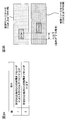
- FIGS. 1A and 1B are diagrams illustrating an example in which DCI and PDSCH are transmitted from a plurality of transmission/reception points.
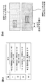
- 2A to 2D are diagrams showing an example of a table in which an AL designated by DCI is defined.
- 3A and 3B are diagrams illustrating an example of a table in which a time offset designated by DCI is defined.
- 4A and 4B are diagrams showing another example of a table in which a time offset designated by DCI is defined.
- FIG. 5: is a figure which shows an example at the time of exchanging the information regarding PDSCH between TRPs.
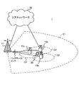
- FIG. 6 is a diagram showing an example of a schematic configuration of a wireless communication system according to an embodiment.
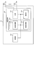
- FIG. 7 is a diagram illustrating an example of the configuration of the base station according to the embodiment.
- FIG. 8 is a diagram showing an example of the configuration of the user terminal according to the embodiment.
- FIG. 9 is a diagram illustrating an example of hardware configurations of a base station and a user terminal according to an embodiment.
- non-coherent DL for example, PDSCH
- transmission in which a non-coherent DL signal (or DL channel) is cooperatively transmitted from a plurality of transmission/reception points may be called NCJT (Non-Coherent Joint Transmission).
- NCJT Non-Coherent Joint Transmission
- a transmission/reception point (TRP) may be read as a transmission point, a reception point, a panel, or a cell.
- Controlling the scheduling of non-coherent PDSCHs transmitted from multiple transmission/reception points using one or more DCIs is also envisioned.
- multiple downlink control channels (or DCI) are used to schedule PDSCHs transmitted from multiple transmission/reception points.
- FIG. 1A shows a case where PDSCHs (for example, PDSCH using NCJT) are transmitted from a plurality of panels to a UE, and in FIG. 1B, PDSCHs (for example, PDSCH using NCJT) are transmitted from a plurality of transmission/reception points (TRPs). Is transmitted to the UE.
- PDSCHs for example, PDSCH using NCJT
- TRPs transmission/reception points
- the first DCI #A that schedules the PDSCH transmitted from the transmission/reception point #A and the second DCI #B that schedules the PDSCH transmitted from the transmission/reception point #B may be transmitted to the UE.
- the inventors of the present invention include, in at least one of the plurality of pieces of downlink control information transmitted within a predetermined range, information regarding other downlink control information (may be referred to as assist information), and The idea was to use it for receiving downlink control information.
- predetermined downlink control information (hereinafter also referred to as predetermined DCI) is replaced with other downlink control information (hereinafter also referred to as other DCI). (Notice) and notify.
- Information related to other DCI may be information that can be used for receiving operation (for example, monitor operation or decoding operation) of other DCI, and may be referred to as assist information. Further, the predetermined DCI and another DCI may be transmitted within a predetermined time range (for example, the same slot). The other DCI may include information about the predetermined DCI.
- a bit field for notifying information about another DCI to a predetermined DCI may be set.
- the UE may control the reception operation for another DCI (or PDCCH) based on a predetermined bit field included in a predetermined DCI.
- the UE can perform the receiving operation for the other DCI based on the information regarding other DCI.
- the predetermined DCI and the other DCI may be DCIs that schedule physical shared channels in the same transmission direction.
- both the predetermined DCI and the other DCI may be DCI (also referred to as UL grant or UL DCI) that schedules the PUSCH.
- both the predetermined DCI and the other DCI may be DCI (also referred to as DL assignment or DL DCI) that schedules PDSCH.
- the predetermined DCI and the other DCI may be transmitted within a predetermined time range (for example, the same slot).
- the same DCI format may be applied to a predetermined DCI and another DCI.
- the predetermined DCI and the other DCI may be DCI format 1_1 transmitted in the same slot.
- the predetermined DCI and the other DCI may be DCIs transmitted from different transmission/reception points within a predetermined time range (for example, the same slot).
- Each transceiving point may be associated with a different DMRS port (or DMRS port group).
- a predetermined DCI and another DCI may be associated with a CCE index and an aggregation level (AL).
- the CCE index values of both the predetermined DCI and the other DCI may be either odd or even.
- the predetermined DCI and the ALs of other DCIs may have mutually overlapping values or may not have mutually overlapping values.
- the information about other DCI (or other PDCCH) included in the predetermined DCI (or the predetermined PDCCH) may be at least one of the following. (1) Presence/absence of other DCIs transmitted in a predetermined time range (eg, same slot) (2) Number of other DCIs transmitted in predetermined time range (eg, same slot) or total number of DCIs (3) PDCCH configuration ID of other DCI (PDCCH-Config ID) (4) Search space ID of another DCI (5) Control Resource Set ID of another DCI (6) Aggregation level of other DCI (7) CCE index of other DCI (8) DCI format of other DCI (9) Relationship of time resource location between other DCI and predetermined DCI (10) Relationship of frequency resource location between other DCI and predetermined DCI
- the UE may omit the reception operation for the other DCI after decoding the predetermined DCI.
- the UE controls to perform reception operation for the N DCIs after decoding the predetermined DCI. You may.
- the UE may selectively perform the receiving operation for the configuration corresponding to the specified ID.
- the UE when the predetermined DCI includes a CCE index of another DCI (for example, an odd CCE index) (the example of (7) above), the UE is limited to the designated CCE index (for example, an odd CCE index). Then, the other DCIs may be monitored.
- the DCI format of another DCI for example, DCI format 0_1
- the UE is limited to the specified DCI format (for example, DCI format 0_1). You may monitor for another DCI.
- the UE moves away from the predetermined DCI by T1 in the time direction.
- the reception operation for another DCI may be performed by limiting the time resource.
- the predetermined DCI includes a positional relationship of frequency resources between another DCI and the predetermined DCI (for example, the offset F1) (example of (9) above), the UE is away from the predetermined DCI by F1 in the frequency direction.
- the reception operation for other DCI may be performed by limiting the frequency resource.
- the UE controls the receiving process for the other DCIs based on the information regarding the other DCIs obtained from the DCI that first performs the receiving process (for example, decoding). By this means, it is possible to reduce the operation load of other DCI reception processing (for example, the number of times of blind decoding).
- FIG. 2 shows an example of the case where the information about other DCIs included in the predetermined DCI is the aggregation level ((6) above).
- the values in the table may be defined in advance in specifications, or may be set in higher layer signaling or the like.
- FIG. 2A and 2B show a case where the aggregation level (AL) of another DCI is designated by 1 bit.
- FIG. 2C and 2D show a case where the aggregation level (AL) of another DCI is designated by 2 bits.
- the UE controls the reception process for another DCI based on the AL related to the other DCI acquired from the predetermined DCI (for example, the DCI that first received and processed).
- reception processing can be performed only for a predetermined AL for other DCIs, and thus the operation load of the reception processing (for example, the number of times of blind decoding) can be reduced.
- FIGS. 3 and 4 show an example of the case where the information about other DCIs included in the predetermined DCI is the relationship of the time resource position between the other DCI and the predetermined DCI ((9) above).
- the values in the table may be defined in advance in specifications, or may be set in higher layer signaling or the like.
- FIG. 3A shows a case where the relationship of the time resource position between another DCI and a predetermined DCI is designated by 1 bit.
- the relationship of the time resource position (time offset) between the other DCI and the predetermined DCI is shown as the interval between the head symbol of the other DCI and the head symbol of the predetermined DCI, but is not limited to this. Absent.
- the UE determines that the time offset between DCI#1 and DCI#2 (eg, other DCI) is larger than the X1 symbol by X2. It is determined that it is less than or equal to the symbol (X2>X1 ⁇ 0). On the other hand, when DCI#1 includes the bit value “0” shown in FIG. 3A, the UE determines that the time offset between DCI#1 and DCI#2 is less than or equal to X1 symbols.
- FIG. 3B shows an example of the time offset between DCIs when the bit value included in DCIs is “1”.
- DCI#1 is TCI#1 (or TRP, for example, when X1 is 2
- the interval (time offset) between the leading symbol of DCI#1 and the leading symbol of DCI#2 is 2 symbols or less.
- bit value “1” may be included for DCI#2 in addition to DCI#1. In this case, it may be assumed that DCI#2 corresponds to the predetermined DCI and DCI#1 corresponds to another DCI.
- FIG. 4A shows a case where the relationship of the time resource position between another DCI and a predetermined DCI is designated by 2 bits.
- the relationship of the time resource position (time offset) between the other DCI and the predetermined DCI is shown as the interval between the head symbol of the other DCI and the head symbol of the predetermined DCI, but is not limited to this. Absent.
- the UE determines the time offset (DCI#2 head) of DCI#1 and DCI#2 (eg, another DCI). It is determined that the symbol-the leading symbol of DCI#1) is greater than or equal to -X2 symbols and less than -X1 symbols. If DCI#1 includes the bit value “10” shown in FIG. 3A, the UE determines that the time offset between DCI#1 and DCI#2 is greater than X1 symbols and less than or equal to X2 symbols.
- DCI#1 includes the bit value “01” shown in FIG. 3A
- the UE determines that the time offset between DCI#1 and DCI#2 is at least ⁇ X1 symbols and less than 0.
- DCI#1 includes the bit value “00” shown in FIG. 3A
- the UE determines that the time offset between DCI#1 and DCI#2 is 0 or more and X1 symbols or less.
- FIG. 4B shows an example of a time offset between DCIs when the bit value included in DCI#1 is “00” and the bit value included in DCI#2 is “01”. For example, when X1 is 2, the interval (time offset) between the leading symbol of DCI#1 and the leading symbol of DCI#2 is 2 symbols or less.
- DCI#2 includes a bit value, it may be assumed that DCI#2 corresponds to a predetermined DCI and DCI#1 corresponds to another DCI.
- the UE controls the reception process for another DCI in consideration of the time offset between the predetermined DCI and the other DCI, based on the time offset information regarding the other DCI acquired from the predetermined DCI.
- the frequency offset can also be defined and applied in the same table as in FIGS. 3A and 4A.
- the base station uses at least one of the following (1) to (10) also shown in the first aspect as information regarding a plurality of DCIs (for example, DCIs corresponding to each TRP) by using higher layer signaling May be notified.
- the base station may set a plurality of candidates (or entries) by higher layer signaling and set activation or deactivation of a predetermined candidate using MAC control information. ..
- Information regarding each DCI to be notified to the UE may be shared between each TRP (or a base station corresponding to each TRP).
- information regarding each DCI (or another DCI) may be quasi-statically transmitted and received between the base stations by using inter-gNB (inter-gNB) signaling (for example, Xn signaling).
- inter-gNB inter-gNB
- Information regarding each DCI may be notified to the UE from a specific (for example, one) TRP or base station, or may be notified to the UE from a plurality of TRPs.
- the UE is notified of the aggregation level (AL) of each DCI using upper layer signaling.
- the UE may be notified (example 1).
- information about the TRP (eg, TRP ID) corresponding to each DCI may also be notified. For example, when DCI#1 and TRP#1 correspond and DCI#2 and TRP#2 correspond, the correspondence relationship between DCI and TRP is notified to the UE.
- the UE may be notified of the correspondence relationship between at least one of PDSCH, codeword (CW), transport block (TB), and DMRS port (or DMRS port group) and DCI.
- Each TRP (or each base station) shares the AL applied to each DCI between the base stations, and controls the transmission of each DCI based on the shared AL information.
- the upper layer signaling is used to notify the UE of the information on the time resource position (eg, time offset) between the DCIs.
- the base station notifies the UE of information regarding the time resource of each DCI transmitted in a predetermined time domain (for example, the same slot).
- An example of the information regarding the time resource of each DCI is shown below.
- DCI#1: 1st to X1th symbol in the control resource set (for example, X1 7)
- DCI#2: 3rd to X2th symbol (for example, X2 9) in the control resource set
- the UE may control the reception process of each DCI based on the time resource notified by higher layer signaling.
- the correspondence relationship with the TRP (or PDSCH, codeword (CW), transport block (TB), DMRS port (or DMRS port group) corresponding to each DCI may be defined in advance in the specifications.
- the base station may notify the UE.
- the UE is notified of information regarding the presence or absence of DCI or the number of DCIs transmitted in a predetermined time domain (for example, each slot) using upper layer signaling.
- the base station may notify any of the following three statuses (3 status) using 2 bits for the number of DCIs in each slot. Note that the number of bits to be applied and the number of states to be notified are examples, and the present invention is not limited to this.
- -State 1 (corresponding to bit value "00"): A maximum of one DCI is transmitted from TRP#1 (or DMRS port group #1, control resource set #1, etc.)-State 2 (bit value "01") Corresponding): TRP#2 (or DMRS port group #2, control resource set #2, etc.) transmits at most one DCI.
- State 3 (corresponding to bit value “10”): Each TRP (or, Up to X (eg, X is the number of TRP) DCIs are transmitted from each DMRS port group, each control resource set, etc.
- the base station may notify the pattern in a predetermined period (time duration) by upper layer signaling. For example, the base station notifies the state of each slot (eg, “00, 10, 01, 10, 00, 10, 01, 10, 00, 10”) as a pattern for 10 slots.
- the UE controls the reception process for each DCI by determining the number of DCIs transmitted in each slot based on the pattern notified by higher layer signaling. Further, the UE may control the DCI reception operation based on the set pattern until a new pattern is set by higher layer signaling. For example, when the UE determines that the number of DCIs transmitted in a certain slot is one, the UE may control not to perform reception processing for other DCIs.
- each base station When multiple TRPs (or base stations) are connected by a backhaul (Non-ideal backhaul) whose delay cannot be ignored, each base station sends information about other DCIs (eg, DCIs corresponding to other TRPs). It becomes difficult to grasp it dynamically.
- DCIs eg, DCIs corresponding to other TRPs.
- upper layer signaling or upper layer signaling and MAC control information
- a plurality of base stations are connected by non-ideal backhaul. Even in the case, the UE and the base station can appropriately grasp the information about each DCI.
- the source of the PDSCH transmission may be a TRP corresponding to the PDSCH transmission, a DMRS port (or DMRS port group), a control resource set, a codeword (CW), or a transport block (TB).
- MCS for each PDSCH that is redundantly transmitted from multiple TRPs due to interference between TRPs is appropriate. May not be selected.
- a plurality of TRPs or base stations coordinately perform PDSCH transmission in a slot.
- a given TRP it becomes possible for a given TRP to select an MCS in consideration of PDSCH transmission from another TRP by grasping whether or not PDSCH is transmitted from another TRP in a certain slot.
- transmission/reception (or sharing) between base stations may be performed using inter-gNB signaling (eg, Xn signaling) (see FIG. 5).
- the Xn signaling may include a UE ID and a bit string pattern corresponding to the PDSCH transmitted (or instructed) to the UE in a predetermined period.
- the base station may notify any of the following three statuses (3 status) by using 2 bits for PDSCH transmission in each slot.
- the number of bits to be applied and the number of states to be notified are examples, and the present invention is not limited to this.
- -State 1 (corresponding to bit value "00"): A maximum of one PDSCH is transmitted from TRP#1 (or DMRS port group #1, control resource set #1, etc.)-State 2 (bit value "01")
- TRP#2 or DMRS port group #2, control resource set #2, etc.
- -State 3 (corresponding to bit value "10"):
- Each TRP (or, Up to X (for example, X is the number of TRP) PDSCHs are transmitted from each DMRS port group, each control resource set, etc.
- the base station may notify the pattern in a predetermined period (time duration) between the base stations by Xn signaling. For example, the base station notifies the state of each slot (for example, “00, 10, 01, 10, 00, 00, 01, 01, 10, 10”) as a pattern for 10 slots.
- Each base station determines the MCS in each slot based on the information (eg, pattern) shared between the base stations.
- the MCS can be determined in cooperation between the base stations (or TRPs).
- the information shared between the base stations may not be notified to the UE.
- the UE may control the PDSCH detection based on the MCS specified by DCI.
- the base station can set an appropriate MCS for PDSCH transmission.
- wireless communication system Wireless communication system
- communication is performed using any of the wireless communication methods according to the above-described embodiments of the present disclosure or a combination thereof.
- FIG. 6 is a diagram showing an example of a schematic configuration of a wireless communication system according to an embodiment.
- the wireless communication system 1 may be a system that realizes communication by using Long Term Evolution (LTE), 5th generation mobile communication system New Radio (5G NR), etc. specified by Third Generation Partnership Project (3GPP). ..
- the wireless communication system 1 may support dual connectivity (Multi-RAT Dual Connectivity (MR-DC)) between multiple Radio Access Technologies (RATs).
- MR-DC has dual connectivity (E-UTRA-NR Dual Connectivity (EN-DC)) with LTE (Evolved Universal Terrestrial Radio Access (E-UTRA)) and NR, and dual connectivity (NR-E) with NR and LTE.
- E-UTRA-NR Dual Connectivity EN-DC
- NR-E Dual Connectivity
- NE-DC Dual Connectivity
- the base station (eNB) of LTE (E-UTRA) is the master node (Master Node (MN)), and the base station (gNB) of NR is the secondary node (Secondary Node (SN)).
- the NR base station (gNB) is the MN, and the LTE (E-UTRA) base station (eNB) is the SN.
- the wireless communication system 1 has dual connectivity between a plurality of base stations within the same RAT (for example, dual connectivity (NR-NR Dual Connectivity (NN-DC)) in which both MN and SN are NR base stations (gNB). )) may be supported.
- dual connectivity NR-NR Dual Connectivity (NN-DC)
- N-DC dual connectivity
- MN and SN are NR base stations (gNB).
- the wireless communication system 1 includes a base station 11 forming a macro cell C1 having a relatively wide coverage and a base station 12 (12a-12c) arranged in the macro cell C1 and forming a small cell C2 narrower than the macro cell C1. You may prepare.
- the user terminal 20 may be located in at least one cell. The arrangement and number of each cell and user terminal 20 are not limited to those shown in the figure.
- the base stations 11 and 12 are not distinguished, they are collectively referred to as the base station 10.
- the user terminal 20 may be connected to at least one of the plurality of base stations 10.
- the user terminal 20 may use at least one of carrier aggregation (Carrier Aggregation (CA)) using multiple component carriers (Component Carrier (CC)) and dual connectivity (DC).
- CA Carrier Aggregation
- CC Component Carrier
- DC dual connectivity
- Each CC may be included in at least one of the first frequency band (Frequency Range 1 (FR1)) and the second frequency band (Frequency Range 2 (FR2)).
- the macro cell C1 may be included in FR1 and the small cell C2 may be included in FR2.
- FR1 may be in a frequency band of 6 GHz or less (sub 6 GHz (sub-6 GHz)), and FR2 may be in a frequency band higher than 24 GHz (above-24 GHz).
- the frequency bands and definitions of FR1 and FR2 are not limited to these, and for example, FR1 may correspond to a frequency band higher than FR2.
- the user terminal 20 may perform communication in each CC using at least one of Time Division Duplex (TDD) and Frequency Division Duplex (FDD).
- TDD Time Division Duplex
- FDD Frequency Division Duplex
- the plurality of base stations 10 may be connected by wire (for example, optical fiber compliant with Common Public Radio Interface (CPRI), X2 interface, etc.) or wirelessly (for example, NR communication).
- wire for example, optical fiber compliant with Common Public Radio Interface (CPRI), X2 interface, etc.
- NR communication for example, when NR communication is used as a backhaul between the base stations 11 and 12, the base station 11 corresponding to the upper station is the Integrated Access Backhaul (IAB) donor, and the base station 12 corresponding to the relay station (relay) is the IAB. It may be called a node.
- IAB Integrated Access Backhaul
- relay station relay station
- the base station 10 may be connected to the core network 30 via another base station 10 or directly.
- the core network 30 may include at least one of, for example, Evolved Packet Core (EPC), 5G Core Network (5GCN), and Next Generation Core (NGC).
- EPC Evolved Packet Core
- 5GCN 5G Core Network
- NGC Next Generation Core
- the user terminal 20 may be a terminal compatible with at least one of communication methods such as LTE, LTE-A, and 5G.
- an orthogonal frequency division multiplexing (Orthogonal Frequency Division Multiplexing (OFDM)) based wireless access method may be used.
- OFDM Orthogonal Frequency Division Multiplexing
- DL Downlink
- UL Uplink
- DFT-s-OFDM Discrete Fourier Transform Spread OFDM
- OFDMA Orthogonal Frequency Division Multiple Access
- SC-FDMA Single Carrier Frequency Division Multiple Access
- the wireless access method may be called a waveform.
- other wireless access methods such as another single carrier transmission method and another multicarrier transmission method may be used as the UL and DL wireless access methods.
- downlink shared channels Physical Downlink Shared Channel (PDSCH)
- broadcast channels Physical Broadcast Channel (PBCH)
- downlink control channels Physical Downlink Control
- an uplink shared channel Physical Uplink Shared Channel (PUSCH)
- an uplink control channel Physical Uplink Control Channel (PUCCH)
- a random access channel that are shared by each user terminal 20.
- Physical Random Access Channel (PRACH) Physical Random Access Channel
- User data, upper layer control information, System Information Block (SIB), etc. are transmitted by PDSCH.
- User data, upper layer control information, and the like may be transmitted by the PUSCH.
- the Master Information Block (MIB) may be transmitted by the PBCH.
- Lower layer control information may be transmitted by the PDCCH.
- the lower layer control information may include downlink control information (Downlink Control Information (DCI)) including scheduling information of at least one of PDSCH and PUSCH, for example.
- DCI Downlink Control Information
- DCI for scheduling PDSCH may be referred to as DL assignment, DL DCI, etc.
- DCI for scheduling PUSCH may be referred to as UL grant, UL DCI, etc.
- PDSCH may be replaced with DL data
- PUSCH may be replaced with UL data.
- a control resource set (COntrol REsource SET (CORESET)) and a search space (search space) may be used to detect the PDCCH.
- CORESET corresponds to a resource for searching DCI.
- the search space corresponds to the search area and the search method of the PDCCH candidates.
- a CORESET may be associated with one or more search spaces. The UE may monitor CORESET associated with a search space based on the search space settings.
- One search space may correspond to PDCCH candidates corresponding to one or more aggregation levels.
- One or more search spaces may be referred to as a search space set.
- the “search space”, “search space set”, “search space setting”, “search space set setting”, “CORESET”, “CORESET setting” and the like of the present disclosure may be read as each other.
- channel state information (Channel State Information (CSI)
- delivery confirmation information for example, Hybrid Automatic Repeat reQuest ACKnowledgement (HARQ-ACK), ACK/NACK, etc.
- scheduling request (Scheduling Request (Scheduling Request ( Uplink Control Information (UCI) including at least one of (SR))
- CSI Channel State Information
- HARQ-ACK Hybrid Automatic Repeat reQuest ACKnowledgement
- ACK/NACK ACK/NACK
- scheduling request Scheduling Request (Scheduling Request ( Uplink Control Information (UCI) including at least one of (SR)
- a random access preamble for establishing a connection with a cell may be transmitted by the PRACH.
- downlink, uplink, etc. may be expressed without adding “link”. Further, it may be expressed without adding “Physical” to the head of each channel.
- a synchronization signal (Synchronization Signal (SS)), a downlink reference signal (Downlink Reference Signal (DL-RS)), etc. may be transmitted.
- a DL-RS a cell-specific reference signal (Cell-specific Reference Signal (CRS)), a channel state information reference signal (Channel State Information Reference Signal (CSI-RS)), and a demodulation reference signal (DeModulation) Reference Signal (DMRS), Positioning Reference Signal (PRS), Phase Tracking Reference Signal (PTRS), etc.
- CRS Cell-specific Reference Signal
- CSI-RS Channel State Information Reference Signal
- DMRS Demodulation reference signal
- PRS Positioning Reference Signal
- PTRS Phase Tracking Reference Signal
- the synchronization signal may be, for example, at least one of a primary synchronization signal (Primary Synchronization Signal (PSS)) and a secondary synchronization signal (Secondary Synchronization Signal (SSS)).
- a signal block including SS (PSS, SSS) and PBCH (and DMRS for PBCH) may be referred to as an SS/PBCH block, SS Block (SSB), or the like. Note that SS and SSB may also be referred to as reference signals.
- the wireless communication system even if the measurement reference signal (Sounding Reference Signal (SRS)), the demodulation reference signal (DMRS), etc. are transmitted as the uplink reference signal (Uplink Reference Signal (UL-RS)). Good.
- the DMRS may be called a user terminal specific reference signal (UE-specific Reference Signal).
- FIG. 7 is a diagram illustrating an example of the configuration of the base station according to the embodiment.
- the base station 10 includes a control unit 110, a transmission/reception unit 120, a transmission/reception antenna 130, and a transmission line interface 140. It should be noted that the control unit 110, the transmission/reception unit 120, the transmission/reception antenna 130, and the transmission path interface 140 may each be provided with one or more.
- the functional blocks of the characteristic part in the present embodiment are mainly shown, and it may be assumed that the base station 10 also has other functional blocks necessary for wireless communication. A part of the processing of each unit described below may be omitted.
- the control unit 110 controls the entire base station 10.
- the control unit 110 can be configured by a controller, a control circuit, and the like described based on common recognition in the technical field of the present disclosure.
- the control unit 110 may control signal generation, scheduling (for example, resource allocation, mapping) and the like.
- the control unit 110 may control transmission/reception using the transmission/reception unit 120, the transmission/reception antenna 130, and the transmission path interface 140, measurement, and the like.
- the control unit 110 may generate data to be transmitted as a signal, control information, a sequence, etc., and transfer the generated data to the transmission/reception unit 120.
- the control unit 110 may perform communication channel call processing (setting, release, etc.), state management of the base station 10, wireless resource management, and the like.
- the transmission/reception unit 120 may include a baseband unit 121, a Radio Frequency (RF) unit 122, and a measurement unit 123.
- the baseband unit 121 may include a transmission processing unit 1211 and a reception processing unit 1212.
- the transmission/reception unit 120 includes a transmitter/receiver, an RF circuit, a baseband circuit, a filter, a phase shifter, a measurement circuit, a transmission/reception circuit, etc., which are explained based on common recognition in the technical field according to the present disclosure. be able to.
- the transmission/reception unit 120 may be configured as an integrated transmission/reception unit, or may be configured by a transmission unit and a reception unit.
- the transmitting unit may include a transmission processing unit 1211 and an RF unit 122.
- the receiving unit may include a reception processing unit 1212, an RF unit 122, and a measuring unit 123.
- the transmission/reception antenna 130 can be configured by an antenna described based on common recognition in the technical field according to the present disclosure, for example, an array antenna or the like.
- the transmitting/receiving unit 120 may transmit the above-mentioned downlink channel, synchronization signal, downlink reference signal, and the like.
- the transmitter/receiver 120 may receive the above-mentioned uplink channel, uplink reference signal, and the like.
- the transmission/reception unit 120 may form at least one of a transmission beam and a reception beam by using digital beamforming (for example, precoding), analog beamforming (for example, phase rotation), or the like.
- digital beamforming for example, precoding
- analog beamforming for example, phase rotation
- the transmission/reception unit 120 processes the Packet Data Convergence Protocol (PDCP) layer and the Radio Link Control (RLC) layer (for example, for data and control information acquired from the control unit 110) (for example, RLC retransmission control), Medium Access Control (MAC) layer processing (for example, HARQ retransmission control), etc. may be performed to generate a bit string to be transmitted.
- PDCP Packet Data Convergence Protocol
- RLC Radio Link Control
- MAC Medium Access Control
- the transmission/reception unit 120 performs channel coding (may include error correction coding), modulation, mapping, filtering, and discrete Fourier transform (Discrete Fourier Transform (DFT)) on the bit string to be transmitted. Processing (as necessary), inverse fast Fourier transform (Inverse Fast Fourier Transform (IFFT)) processing, precoding, digital-analog conversion, and other transmission processing may be performed to output the baseband signal.
- channel coding may include error correction coding
- modulation modulation
- mapping mapping
- filtering discrete Fourier transform
- DFT discrete Fourier Transform
- IFFT inverse fast Fourier transform
- precoding coding
- digital-analog conversion digital-analog conversion
- the transmitter/receiver 120 may perform modulation, filtering, amplification, etc. on the baseband signal in a radio frequency band, and transmit the radio frequency band signal via the transmission/reception antenna 130. ..
- the transmission/reception unit 120 may perform amplification, filtering, demodulation to a baseband signal, etc., on the signal in the radio frequency band received by the transmission/reception antenna 130.
- the transmission/reception unit 120 performs analog-digital conversion, fast Fourier transform (Fast Fourier Transform (FFT)) processing, and inverse discrete Fourier transform (Inverse Discrete Fourier Transform (IDFT) on the acquired baseband signal. ))
- FFT Fast Fourier transform
- IDFT inverse discrete Fourier transform
- Apply reception processing such as processing (if necessary), filtering, demapping, demodulation, decoding (may include error correction decoding), MAC layer processing, RLC layer processing, and PDCP layer processing, User data and the like may be acquired.
- the transmission/reception unit 120 may perform measurement on the received signal.
- the measurement unit 123 may perform Radio Resource Management (RRM) measurement, Channel State Information (CSI) measurement, etc. based on the received signal.
- the measurement unit 123 receives power (for example, Reference Signal Received Power (RSRP)), reception quality (for example, Reference Signal Received Quality (RSRQ), Signal to Interference plus Noise Ratio (SINR), Signal to Noise Ratio (SNR)).
- Signal strength for example, Received Signal Strength Indicator (RSSI)
- channel information for example, CSI
- the measurement result may be output to the control unit 110.
- the transmission path interface 140 transmits/receives signals (backhaul signaling) to/from devices included in the core network 30, other base stations 10, and the like, and user data (user plane data) for the user terminal 20 and a control plane. Data or the like may be acquired or transmitted.
- the transmission unit and the reception unit of the base station 10 may be configured by at least one of the transmission/reception unit 120, the transmission/reception antenna 130, and the transmission path interface 140.
- the transmission/reception unit 120 transmits downlink control information using the downlink control channel.
- the transmission/reception unit 120 may include information regarding other downlink control information (or each downlink control information) in at least one of the predetermined downlink control information and the information notified by higher layer signaling, and transmit the information.
- the control unit 110 may perform control such that predetermined downlink control information and other downlink control information are transmitted from transmission/reception points in which the physical shared channel to be scheduled has the same transmission direction, the downlink control information format is the same, or different. Good.
- FIG. 8 is a diagram showing an example of the configuration of the user terminal according to the embodiment.
- the user terminal 20 includes a control unit 210, a transmission/reception unit 220, and a transmission/reception antenna 230. Note that each of the control unit 210, the transmission/reception unit 220, and the transmission/reception antenna 230 may be provided with one or more.
- the functional blocks of the characteristic part in the present embodiment are mainly shown, and the user terminal 20 may be assumed to also have other functional blocks necessary for wireless communication. A part of the processing of each unit described below may be omitted.
- the control unit 210 controls the entire user terminal 20.
- the control unit 210 can be configured by a controller, a control circuit, and the like that are described based on common recognition in the technical field according to the present disclosure.
- the control unit 210 may control signal generation, mapping, and the like.
- the control unit 210 may control transmission/reception, measurement, and the like using the transmission/reception unit 220 and the transmission/reception antenna 230.
- the control unit 210 may generate data to be transmitted as a signal, control information, a sequence, etc., and transfer the data to the transmission/reception unit 220.
- the transmitter/receiver 220 may include a baseband unit 221, an RF unit 222, and a measurement unit 223.
- the baseband unit 221 may include a transmission processing unit 2211 and a reception processing unit 2212.
- the transmitter/receiver 220 may include a transmitter/receiver, an RF circuit, a baseband circuit, a filter, a phase shifter, a measurement circuit, a transmitter/receiver circuit, and the like, which are described based on common knowledge in the technical field of the present disclosure.
- the transmission/reception unit 220 may be configured as an integrated transmission/reception unit, or may be configured by a transmission unit and a reception unit.
- the transmission unit may include a transmission processing unit 2211 and an RF unit 222.
- the reception unit may include a reception processing unit 2212, an RF unit 222, and a measurement unit 223.
- the transmission/reception antenna 230 can be configured by an antenna described based on common recognition in the technical field according to the present disclosure, for example, an array antenna or the like.
- the transmitter/receiver 220 may receive the above-mentioned downlink channel, synchronization signal, downlink reference signal, and the like.
- the transceiver 220 may transmit the above-mentioned uplink channel, uplink reference signal, and the like.
- the transmission/reception unit 220 may form at least one of a transmission beam and a reception beam by using digital beamforming (for example, precoding), analog beamforming (for example, phase rotation), or the like.
- digital beamforming for example, precoding
- analog beamforming for example, phase rotation
- the transmission/reception unit 220 processes the PDCP layer, the RLC layer (for example, RLC retransmission control), and the MAC layer (for example, for the data and control information acquired from the control unit 210). , HARQ retransmission control) or the like to generate a bit string to be transmitted.
- the transmission/reception unit 220 (transmission processing unit 2211) performs channel coding (which may include error correction coding), modulation, mapping, filter processing, DFT processing (if necessary), and IFFT processing on the bit string to be transmitted.
- the baseband signal may be output by performing transmission processing such as precoding and digital-analog conversion.
- the transmission/reception unit 220 (transmission processing unit 2211) is configured to transmit the channel using a DFT-s-OFDM waveform when transform precoding is enabled for the channel (for example, PUSCH).
- the DFT process may be performed as the transmission process, or otherwise, the DFT process may not be performed as the transmission process.
- the transmitter/receiver 220 may perform modulation, filtering, amplification, etc. on the baseband signal in the radio frequency band, and transmit the radio frequency band signal via the transmission/reception antenna 230. ..
- the transmission/reception unit 220 may perform amplification, filtering, demodulation to a baseband signal, etc., on a signal in the radio frequency band received by the transmission/reception antenna 230.
- the transmission/reception unit 220 (reception processing unit 2212) performs analog-digital conversion, FFT processing, IDFT processing (if necessary), filter processing, demapping, demodulation, decoding (error correction) on the acquired baseband signal.
- User data and the like may be acquired by applying reception processing such as MAC layer processing, RLC layer processing, and PDCP layer processing.
- the transmission/reception unit 220 may perform measurement on the received signal.
- the measurement unit 223 may perform RRM measurement, CSI measurement, etc. based on the received signal.
- the measurement unit 223 may measure received power (for example, RSRP), reception quality (for example, RSRQ, SINR, SNR), signal strength (for example, RSSI), channel information (for example, CSI), and the like.
- the measurement result may be output to the control unit 210.
- the transmission unit and the reception unit of the user terminal 20 may be configured by at least one of the transmission/reception unit 220 and the transmission/reception antenna 230.
- the transmission/reception unit 220 monitors and receives the downlink control channel candidates corresponding to the downlink control information transmitted from each of the plurality of transmission/reception points.
- the transmitter/receiver 220 may receive other downlink control information transmitted within a predetermined period based on at least one of the information included in the predetermined downlink control information and the information notified by higher layer signaling.
- the control unit 210 receives other downlink control information transmitted within a predetermined period (for example, the same slot) based on at least one of the information included in the predetermined downlink control information and the information notified by higher layer signaling. Control the process.
- the predetermined downlink control information and other downlink control information may be transmitted from transmission/reception points in which the physical shared channel to be scheduled has the same transmission direction, the same downlink control information format, or different.
- the information included in at least one of the predetermined downlink control information and the information notified by higher layer signaling is the downlink control channel configuration ID, search space ID, control resource set ID, aggregation level of other downlink control information, It may be at least one of the control channel element ID and the downlink control information format.
- At least one of the information included in the predetermined downlink control information and the information notified by higher layer signaling is the positional relationship of time resources and the positional relationship of frequency resources between the predetermined downlink control information and other downlink control information. Of at least one of the above.
- the control unit 210 may receive upper layer signaling that specifies the content of information included in predetermined downlink control information.
- each functional block may be realized by using one device physically or logically coupled, or directly or indirectly (for example, two or more devices physically or logically separated). , Wired, wireless, etc.) and may be implemented using these multiple devices.
- the functional blocks may be realized by combining the one device or the plurality of devices with software.
- the functions include judgment, determination, judgment, calculation, calculation, processing, derivation, investigation, search, confirmation, reception, transmission, output, access, solution, selection, selection, establishment, comparison, assumption, expectation, and deemed. , Broadcasting (notifying), notifying (communicating), forwarding (forwarding), configuring (reconfiguring), allocating (allocating, mapping), allocating (assigning), etc.
- a functional block (configuration unit) that causes transmission to function may be referred to as a transmitting unit (transmitting unit), a transmitter (transmitter), or the like.
- the implementation method is not particularly limited.
- the base station, the user terminal, and the like may function as a computer that performs the process of the wireless communication method of the present disclosure.
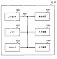
- FIG. 9 is a diagram illustrating an example of hardware configurations of a base station and a user terminal according to an embodiment.
- the base station 10 and the user terminal 20 described above may be physically configured as a computer device including a processor 1001, a memory 1002, a storage 1003, a communication device 1004, an input device 1005, an output device 1006, a bus 1007, and the like. ..
- the terms such as a device, a circuit, a device, a section, and a unit are interchangeable with each other.
- the hardware configurations of the base station 10 and the user terminal 20 may be configured to include one or a plurality of each device illustrated in the figure, or may be configured not to include some devices.
- processor 1001 may be implemented by one or more chips.
- the processor 1001 For each function in the base station 10 and the user terminal 20, for example, by causing a predetermined software (program) to be loaded on hardware such as the processor 1001 and the memory 1002, the processor 1001 performs calculation and communication via the communication device 1004. Is controlled, and at least one of reading and writing of data in the memory 1002 and the storage 1003 is controlled.
- a predetermined software program
- the processor 1001 operates an operating system to control the entire computer, for example.
- the processor 1001 may be configured by a central processing unit (CPU) including an interface with peripheral devices, a control device, an arithmetic device, a register, and the like.
- CPU central processing unit
- the control unit 110 (210) and the transmission/reception unit 120 (220) described above may be realized by the processor 1001.
- the processor 1001 reads a program (program code), software module, data, and the like from at least one of the storage 1003 and the communication device 1004 into the memory 1002, and executes various processes according to these.
- a program program code
- the control unit 110 may be realized by a control program stored in the memory 1002 and operating in the processor 1001, and may be realized similarly for other functional blocks.
- the memory 1002 is a computer-readable recording medium, and for example, at least Read Only Memory (ROM), Erasable Programmable ROM (EPROM), Electrically EPROM (EEPROM), Random Access Memory (RAM), and other appropriate storage media. It may be configured by one.
- the memory 1002 may be called a register, a cache, a main memory (main storage device), or the like.
- the memory 1002 may store an executable program (program code), a software module, etc. for implementing the wireless communication method according to an embodiment of the present disclosure.
- the storage 1003 is a computer-readable recording medium, for example, a flexible disk, a floppy (registered trademark) disk, a magneto-optical disk (for example, a compact disk (Compact Disc ROM (CD-ROM), etc.), a digital versatile disk, Blu-ray® disk), removable disk, hard disk drive, smart card, flash memory device (eg, card, stick, key drive), magnetic stripe, database, server, and/or any other suitable storage medium May be configured by.
- the storage 1003 may be called an auxiliary storage device.
- the communication device 1004 is hardware (transmission/reception device) for performing communication between computers via at least one of a wired network and a wireless network, and is also called, for example, a network device, a network controller, a network card, a communication module, or the like.
- the communication device 1004 for example, realizes at least one of frequency division duplex (Frequency Division Duplex (FDD)) and time division duplex (Time Division Duplex (TDD)), a high frequency switch, a duplexer, a filter, a frequency synthesizer, and the like. May be included.
- FDD Frequency Division Duplex
- TDD Time Division Duplex
- the transmission/reception unit 120 (220) and the transmission/reception antenna 130 (230) described above may be realized by the communication device 1004.
- the transmitter/receiver 120 (220) may be physically or logically separated from the transmitter 120a (220a) and the receiver 120b (220b).
- the input device 1005 is an input device (eg, keyboard, mouse, microphone, switch, button, sensor, etc.) that receives an input from the outside.
- the output device 1006 is an output device (for example, a display, a speaker, a Light Emitting Diode (LED) lamp, etc.) that outputs to the outside.
- the input device 1005 and the output device 1006 may be integrated (for example, a touch panel).
- Each device such as the processor 1001 and the memory 1002 is connected by a bus 1007 for communicating information.
- the bus 1007 may be configured by using a single bus, or may be configured by using a different bus for each device.
- the base station 10 and the user terminal 20 include a microprocessor, a digital signal processor (DSP), an Application Specific Integrated Circuit (ASIC), a Programmable Logic Device (PLD), a Field Programmable Gate Array (FPGA), and the like. It may be configured to include hardware, and part or all of each functional block may be realized by using the hardware. For example, the processor 1001 may be implemented using at least one of these hardware.
- DSP digital signal processor
- ASIC Application Specific Integrated Circuit
- PLD Programmable Logic Device
- FPGA Field Programmable Gate Array
- channel, symbol and signal may be read as each other.
- the signal may also be a message.
- the reference signal may be abbreviated as RS, and may be referred to as a pilot, a pilot signal, or the like depending on the applied standard.
- a component carrier Component Carrier (CC)
- CC Component Carrier
- a radio frame may be composed of one or more periods (frames) in the time domain.
- Each of the one or more periods (frames) forming the radio frame may be referred to as a subframe.
- a subframe may be composed of one or more slots in the time domain.
- the subframe may have a fixed time length (eg, 1 ms) that does not depend on numerology.
- the numerology may be a communication parameter applied to at least one of transmission and reception of a certain signal or channel.
- the numerology includes, for example, subcarrier spacing (SubCarrier Spacing (SCS)), bandwidth, symbol length, cyclic prefix length, transmission time interval (Transmission Time Interval (TTI)), number of symbols per TTI, and radio frame configuration. , At least one of a specific filtering process performed by the transceiver in the frequency domain and a specific windowing process performed by the transceiver in the time domain.
- a slot may be composed of one or more symbols in the time domain (Orthogonal Frequency Division Multiplexing (OFDM) symbol, Single Carrier Frequency Division Multiple Access (SC-FDMA) symbol, etc.).
- OFDM Orthogonal Frequency Division Multiplexing
- SC-FDMA Single Carrier Frequency Division Multiple Access
- the slot may be a time unit based on numerology.
- a slot may include multiple minislots. Each minislot may be composed of one or more symbols in the time domain. The minislot may also be called a subslot. Minislots may be configured with a smaller number of symbols than slots.
- a PDSCH (or PUSCH) transmitted in a time unit larger than a minislot may be referred to as PDSCH (PUSCH) mapping type A.
- the PDSCH (or PUSCH) transmitted using the minislot may be referred to as PDSCH (PUSCH) mapping type B.
- Radio frame, subframe, slot, minislot, and symbol all represent the time unit for signal transmission. Radio frames, subframes, slots, minislots, and symbols may have different names corresponding to them. It should be noted that time units such as frames, subframes, slots, minislots, and symbols in the present disclosure may be interchanged with each other.
- one subframe may be called a TTI
- a plurality of consecutive subframes may be called a TTI
- one slot or one minislot may be called a TTI. That is, at least one of the subframe and the TTI may be a subframe (1 ms) in existing LTE, a period shorter than 1 ms (eg, 1-13 symbols), or a period longer than 1 ms. May be
- the unit representing the TTI may be called a slot, a minislot, etc. instead of a subframe.
- TTI means, for example, a minimum time unit of scheduling in wireless communication.
- the base station performs scheduling to allocate radio resources (frequency bandwidth that can be used in each user terminal, transmission power, etc.) to each user terminal in units of TTI.
- the definition of TTI is not limited to this.
- the TTI may be a transmission time unit such as a channel-encoded data packet (transport block), a code block, a codeword, or a processing unit such as scheduling or link adaptation.
- transport block channel-encoded data packet
- code block code block
- codeword codeword
- processing unit such as scheduling or link adaptation.
- one slot or one minislot is called a TTI
- one or more TTIs may be the minimum time unit for scheduling.
- the number of slots (minislot number) that constitutes the minimum time unit of the scheduling may be controlled.
- a TTI having a time length of 1 ms may be called a normal TTI (TTI in 3GPP Rel. 8-12), a normal TTI, a long TTI, a normal subframe, a normal subframe, a long subframe, a slot, or the like.
- a TTI shorter than the normal TTI may be called a shortened TTI, a short TTI, a partial TTI (partial or fractional TTI), a shortened subframe, a short subframe, a minislot, a subslot, a slot, and the like.
- a long TTI (eg, normal TTI, subframe, etc.) may be read as a TTI having a time length exceeding 1 ms, and a short TTI (eg, shortening TTI, etc.) is less than the TTI length of the long TTI and is 1 ms. It may be read as a TTI having the above TTI length.
- a resource block is a resource allocation unit in the time domain and the frequency domain, and may include one or a plurality of continuous subcarriers in the frequency domain.
- the number of subcarriers included in the RB may be the same regardless of the numerology, and may be 12, for example.
- the number of subcarriers included in the RB may be determined based on numerology.
- the RB may include one or more symbols in the time domain and may be one slot, one minislot, one subframe, or one TTI in length.
- One TTI, one subframe, etc. may be configured by one or a plurality of resource blocks.
- One or more RBs are a physical resource block (Physical RB (PRB)), a subcarrier group (Sub-Carrier Group (SCG)), a resource element group (Resource Element Group (REG)), a PRB pair, and an RB. It may be called a pair or the like.
- a resource block may be composed of one or more resource elements (Resource Element (RE)).
- RE resource elements
- one RE may be a radio resource area of one subcarrier and one symbol.
- Bandwidth Part (may be called partial bandwidth etc.) represents a subset of continuous common RBs (common resource blocks) for a certain neurology in a certain carrier. Good.
- the common RB may be specified by the index of the RB based on the common reference point of the carrier.
- PRBs may be defined in a BWP and numbered within that BWP.
- BWP may include UL BWP (BWP for UL) and DL BWP (BWP for DL).
- BWP UL BWP
- BWP for DL DL BWP
- One or more BWPs may be configured in one carrier for the UE.
- At least one of the configured BWPs may be active, and the UE does not have to expect to send and receive a given signal/channel outside the active BWP.
- “cell”, “carrier”, and the like in the present disclosure may be read as “BWP”.
- the structure of the radio frame, subframe, slot, minislot, symbol, etc. described above is merely an example.
- the number of subframes included in a radio frame, the number of slots per subframe or radio frame, the number of minislots included in a slot, the number of symbols and RBs included in a slot or minislot, and included in RBs The number of subcarriers, the number of symbols in the TTI, the symbol length, the cyclic prefix (CP) length, and the like can be variously changed.
- the information, parameters, etc. described in the present disclosure may be represented by using an absolute value, may be represented by using a relative value from a predetermined value, or by using other corresponding information. May be represented.
- the radio resource may be indicated by a predetermined index.
- data, instructions, commands, information, signals, bits, symbols, chips, etc. that may be referred to throughout the above description include voltage, current, electromagnetic waves, magnetic fields or magnetic particles, optical fields or photons, or any of these. May be represented by a combination of
- Information and signals may be output from the upper layer to at least one of the lower layer and the lower layer to the upper layer.
- Information, signals, etc. may be input and output via a plurality of network nodes.
- Input/output information, signals, etc. may be stored in a specific location (for example, memory), or may be managed using a management table. Information, signals, etc. that are input and output can be overwritten, updated or added. The output information, signal, etc. may be deleted. The input information, signal, etc. may be transmitted to another device.
- notification of information is not limited to the aspect/embodiment described in the present disclosure, and may be performed using another method.
- notification of information in the present disclosure includes physical layer signaling (for example, downlink control information (Downlink Control Information (DCI)), uplink control information (Uplink Control Information (UCI))), upper layer signaling (for example, Radio Resource Control). (RRC) signaling, broadcast information (master information block (Master Information Block (MIB)), system information block (System Information Block (SIB)), etc.), Medium Access Control (MAC) signaling), other signals or a combination thereof May be implemented by.
- DCI Downlink Control Information
- UCI Uplink Control Information
- RRC Radio Resource Control
- MIB Master Information Block
- SIB System Information Block
- MAC Medium Access Control
- the physical layer signaling may also be called Layer 1/Layer 2 (L1/L2) control information (L1/L2 control signal), L1 control information (L1 control signal), and the like.
- the RRC signaling may be called an RRC message, and may be, for example, an RRC connection setup (RRC Connection Setup) message, an RRC connection reconfiguration message, or the like.
- the MAC signaling may be notified using, for example, a MAC control element (MAC Control Element (CE)).
- CE MAC Control Element
- the notification of the predetermined information is not limited to the explicit notification, and may be implicitly (for example, by not issuing the notification of the predetermined information or another information). May be carried out).
- the determination may be performed by a value represented by 1 bit (0 or 1), or may be performed by a boolean value represented by true or false. , May be performed by comparison of numerical values (for example, comparison with a predetermined value).
- software, instructions, information, etc. may be sent and received via a transmission medium.
- the software uses at least one of wired technology (coaxial cable, optical fiber cable, twisted pair, digital subscriber line (DSL), etc.) and wireless technology (infrared, microwave, etc.) , Servers, or other remote sources, these wired and/or wireless technologies are included within the definition of transmission media.
- Network may mean a device (eg, a base station) included in the network.
- precoding "precoding weight”
- QCL Quality of Co-Location
- TCI state "Transmission Configuration Indication state”
- space "Spatial relation”
- spatialal domain filter "transmission power”
- phase rotation "antenna port”
- antenna port group "layer”
- number of layers Terms such as “rank”, “resource”, “resource set”, “resource group”, “beam”, “beam width”, “beam angle”, “antenna”, “antenna element”, and “panel” are interchangeable.
- base station BS
- wireless base station fixed station
- NodeB NodeB
- eNB eNodeB
- gNB gNodeB
- Access point "Transmission Point (TP)", “Reception Point (RP)”, “Transmission/Reception Point (TRP)”, “Panel”
- Cell Cell
- femto cell femto cell
- pico cell femto cell
- a base station can accommodate one or more (eg, three) cells.
- a base station accommodates multiple cells, the entire coverage area of the base station can be divided into multiple smaller areas, each smaller area being defined by a base station subsystem (for example, a small indoor base station (Remote Radio Head (RRH))) to provide communication services.
- a base station subsystem for example, a small indoor base station (Remote Radio Head (RRH))
- RRH Remote Radio Head
- the term "cell” or “sector” refers to part or all of the coverage area of at least one of a base station and a base station subsystem providing communication services in this coverage.
- MS Mobile Station
- UE User Equipment
- a mobile station is a subscriber station, mobile unit, subscriber unit, wireless unit, remote unit, mobile device, wireless device, wireless communication device, remote device, mobile subscriber station, access terminal, mobile terminal, wireless terminal, remote terminal. , Handset, user agent, mobile client, client or some other suitable term.
- At least one of the base station and the mobile station may be called a transmission device, a reception device, a wireless communication device, or the like.
- the base station and the mobile station may be a device mounted on a mobile body, the mobile body itself, or the like.
- the moving body may be a vehicle (eg, car, airplane, etc.), an unmanned moving body (eg, drone, self-driving car, etc.), or a robot (manned or unmanned).
- At least one of the base station and the mobile station also includes a device that does not necessarily move during a communication operation.
- at least one of the base station and the mobile station may be an Internet of Things (IoT) device such as a sensor.
- IoT Internet of Things
- the base station in the present disclosure may be replaced by the user terminal.
- the communication between the base station and the user terminal is replaced with communication between a plurality of user terminals (eg, may be called Device-to-Device (D2D), Vehicle-to-Everything (V2X), etc.)
- D2D Device-to-Device
- V2X Vehicle-to-Everything
- each aspect/embodiment of the present disclosure may be applied.
- the user terminal 20 may have the function of the base station 10 described above.
- the words such as “up” and “down” may be replaced with the words corresponding to the communication between terminals (for example, “side”).
- the uplink channel and the downlink channel may be replaced with the side channel.
- the user terminal in the present disclosure may be replaced by the base station.
- the base station 10 may have the function of the user terminal 20 described above.
- the operation supposed to be performed by the base station may be performed by its upper node in some cases.
- various operations performed for communication with a terminal include a base station and one or more network nodes other than the base station (for example, Mobility Management Entity (MME), Serving-Gateway (S-GW), etc. are conceivable, but not limited to these) or a combination of these is clear.
- MME Mobility Management Entity
- S-GW Serving-Gateway
- each aspect/embodiment described in the present disclosure may be used alone, may be used in combination, or may be switched according to execution. Further, the order of the processing procedure, sequence, flowchart, etc. of each aspect/embodiment described in the present disclosure may be changed as long as there is no contradiction. For example, the methods described in this disclosure present elements of the various steps in a sample order, and are not limited to the specific order presented.
- LTE Long Term Evolution
- LTE-A LTE-Advanced
- LTE-B LTE-Beyond
- SUPER 3G IMT-Advanced
- 4G 4th generation mobile communication system
- 5G 5th generation mobile communication system
- Future Radio Access FAA
- New-Radio Access Technology RAT
- NR New Radio
- NX New radio access
- FX Future generation radio access
- GSM Global System for Mobile communications
- CDMA2000 CDMA2000
- Ultra Mobile Broadband UMB
- IEEE 802.11 Wi-Fi (registered trademark)
- IEEE 802.11 WiMAX (registered trademark)
- IEEE 802.11 WiMAX (registered trademark)
- IEEE 802.11 WiMAX (registered trademark)
- Ultra-WideBand (UWB), Bluetooth (registered trademark), a system using another appropriate wireless communication method, a next-generation system extended based on these, and the like may be applied.
- a plurality of systems may be combined and applied (for example, a combination of LTE or LTE-A and 5G).
- the phrase “based on” does not mean “based only on,” unless expressly specified otherwise. In other words, the phrase “based on” means both "based only on” and “based at least on.”
- references to elements using the designations “first,” “second,” etc. as used in this disclosure does not generally limit the amount or order of those elements. These designations may be used in this disclosure as a convenient way to distinguish between two or more elements. Thus, references to first and second elements do not mean that only two elements may be employed or that the first element must precede the second element in any way.
- determining may encompass a wide variety of actions.
- judgment means “judging", “calculating”, “computing”, “processing”, “deriving”, “investigating”, “searching” (looking up, search, inquiry) ( For example, it may be considered to be a “decision” for a search in a table, database or another data structure), ascertaining, etc.
- “decision (decision)” means receiving (eg, receiving information), transmitting (eg, transmitting information), input (input), output (output), access ( Accessing) (eg, accessing data in memory) and the like may be considered to be a “decision.”
- judgment (decision) is regarded as “decision (decision)” of resolving, selecting, choosing, choosing, establishing, establishing, comparing, etc. Good. That is, “determination (decision)” may be regarded as “determination (decision)” of some operation.
- connection refers to any direct or indirect connection or coupling between two or more elements. And may include the presence of one or more intermediate elements between two elements that are “connected” or “coupled” to each other.
- the connections or connections between the elements may be physical, logical, or a combination thereof. For example, “connection” may be read as “access”.
- radio frequency domain microwave Regions
- electromagnetic energy having wavelengths in the light (both visible and invisible) region, etc. can be used to be considered “connected” or “coupled” to each other.
- the term “A and B are different” may mean “A and B are different from each other”.
- the term may mean that “A and B are different from C”.
- the terms “remove”, “coupled” and the like may be construed as “different” as well.
Landscapes
- Engineering & Computer Science (AREA)
- Computer Networks & Wireless Communication (AREA)
- Signal Processing (AREA)
- Mobile Radio Communication Systems (AREA)
Abstract
複数の送受信ポイントを利用して通信を行う場合であっても通信を適切に行うために、本開示のユーザ端末の一態様は、複数の送受信ポイントからそれぞれ送信される下り制御情報に対応する下り制御チャネル候補をモニタして受信を行う受信部と、前記所定の下り制御情報に含まれる情報及び上位レイヤシグナリングで通知される情報の少なくとも一つに基づいて所定期間内に送信される他の下り制御情報の受信処理を制御する制御部と、を有する。
Description
本開示は、次世代移動通信システムにおけるユーザ端末及び無線通信方法に関する。
Universal Mobile Telecommunications System(UMTS)ネットワークにおいて、更なる高速データレート、低遅延などを目的としてLong Term Evolution(LTE)が仕様化された(非特許文献1)。また、LTE(Third Generation Partnership Project(3GPP) Release(Rel.)8、9)の更なる大容量、高度化などを目的として、LTE-Advanced(3GPP Rel.10-14)が仕様化された。
LTEの後継システム(例えば、5th generation mobile communication system(5G)、5G+(plus)、New Radio(NR)、3GPP Rel.15以降などともいう)も検討されている。
既存のLTEシステム(例えば、LTE Rel.8-13)では、ユーザ端末(UE:User Equipment)は、無線基地局からの下り制御情報(Downlink Control Information(DCI)、DLアサインメント等ともいう)に基づいて、下り共有チャネル(例えば、Physical Downlink Shared Channel(PDSCH))の受信を制御する。また、ユーザ端末は、DCI(ULグラント等ともいう)に基づいて、上り共有チャネル(例えば、Physical Uplink Shared Channel(PUSCH))の送信を制御する。
将来の無線通信システム(例えば、NR、5G、5G+又はRel.16以降)では、ビームフォーミング(Beam Forming(BF))を利用して通信を行うことが検討されている。BFを利用した通信品質を向上するために、複数の信号間の疑似コロケーション(Quasi-Co-Location(QCL))の関係(QCL関係)を考慮して信号の送信及び受信の少なくとも一つを制御することが検討されている。
また、将来の無線通信システムでは、複数の送受信ポイントからノンコヒーレント(non-coherent transmission)となるDL信号(例えば、PDSCH)が協調して送信されることも想定される。この場合、1又は複数の下り制御情報(又はPDCCH)を利用して、複数の送受信ポイントから送信されるPDSCHのスケジューリングを制御することも考えられる。
しかし、複数の送受信ポイントから送信されるPDSCHのスケジューリングを1以上のDCIを用いて制御する場合、当該DCIの受信処理をどのように制御するかが問題となる。例えば、UEは、DCIを受信するために、当該DCIの送信に利用される下り制御チャネル(又は、下り制御チャネル候補)をモニタする必要があるが、具体的な処理については十分に検討されていない。下り制御情報又は下り制御チャネルの受信処理が適切に行われない場合、複数の送受信ポイントを利用した通信の品質又はスループットが劣化するおそれがある。
本開示はかかる点に鑑みてなされたものであり、複数の送受信ポイントを利用して通信を行う場合であっても通信を適切に行うことが可能なユーザ端末及び無線通信方法を提供することを目的の一つとする。
本開示の一態様に係るユーザ端末は、複数の送受信ポイントからそれぞれ送信される下り制御情報に対応する下り制御チャネル候補をモニタして受信を行う受信部と、前記所定の下り制御情報に含まれる情報及び上位レイヤシグナリングで通知される情報の少なくとも一つに基づいて所定期間内に送信される他の下り制御情報の受信処理を制御する制御部と、を有することを特徴とする。
本開示の一態様によれば、複数の送受信ポイントを利用して通信を行う場合であっても通信を適切に行うことができる。
将来の無線通信システム(例えば、Rel.16以降)では、複数の送受信ポイントからそれぞれノンコヒーレントなDL(例えば、PDSCH)送信が行われることが検討されている。複数の送受信ポイントからノンコヒーレントとなるDL信号(又は、DLチャネル)を協調して行う送信は、NCJT(Non-Coherent Joint Transmission)と呼んでもよい。また、本明細書において、送受信ポイント(TRP)は、送信ポイント、受信ポイント、パネル(panel)、又はセルと読み替えられてもよい。
複数の送受信ポイントからそれぞれ送信されるノンコヒーレントのPDSCHのスケジューリングを1以上のDCIを用いて制御することも想定される。一例として、複数の送受信ポイントから送信されるPDSCHをスケジューリングするために、複数の下り制御チャネル(又は、DCI)が利用される。
図1Aでは、複数のパネルからPDSCH(例えば、NCJTを利用したPDSCH)がUEに送信される場合を示し、図1Bでは、複数の送受信ポイント(TRP)からPDSCH(例えば、NCJTを利用したPDSCH)がUEに送信される場合を示している。
この場合、各送受信ポイント(例えば、パネル又はTRP)から送信されるPDSCHのスケジューリング用にDCIを別々に設定することも考えられる。例えば、送受信ポイント#Aから送信されるPDSCHをスケジューリングする第1のDCI#Aと、送受信ポイント#Bから送信されるPDSCHをスケジューリングする第2のDCI#BをUEに送信する構成としてもよい。
このように、複数の送受信ポイントからそれぞれPDSCHが送信される場合、各PDSCHに対応するDCI又はPDCCHのモニタリングをどのように制御するかが問題となる。例えば、複数の送受信ポイントから送信される複数のPDCCHのモニタリングを行う場合、UEの受信動作(例えば、モニタ動作、又は復号動作)をどのように制御するかが問題となる。
本発明者等は、本開示の一態様として、所定範囲内で送信される複数の下り制御情報の少なくとも一つに他の下り制御情報に関する情報(アシスト情報と呼んでもよい)を含め、他の下り制御情報の受信処理に利用することを着想した。
以下、本実施の形態について、図面を参照して詳細に説明する。各実施の態様は単独で利用してもよいし、組み合わせて利用してもよい。なお、以下に示す送受信ポイントは、パネル及び送受信ポイントの少なくとも一方に読み替えてもよい。
(第1の態様)
第1の態様では、複数の送受信ポイントを利用した通信がサポートされる無線通信システムにおいて、所定の下り制御情報(以下、所定のDCIとも記す)に他の下り制御情報(以下、他のDCIとも記す)に関する情報を含めて通知する。
第1の態様では、複数の送受信ポイントを利用した通信がサポートされる無線通信システムにおいて、所定の下り制御情報(以下、所定のDCIとも記す)に他の下り制御情報(以下、他のDCIとも記す)に関する情報を含めて通知する。
他のDCIに関する情報は、他のDCIの受信動作(例えば、モニタ動作又は復号動作)に利用できる情報であってもよく、アシスト情報と呼ばれてもよい。また、所定のDCIと、他のDCIは所定時間範囲(例えば、同一スロット)内で送信される構成としてもよい。他のDCIに所定のDCIに関する情報が含まれていてもよい。
例えば、所定のDCIに他のDCIに関する情報を通知するためのビットフィールドが設定されてもよい。UEは、所定のDCIに含まれる所定ビットフィールドに基づいて、他のDCI(又は、PDCCH)に対する受信動作を制御すればよい。
このように、所定DCIに他のDCIに関する情報を含めることにより、UEは、他のDCIに関する情報に基づいて当該他のDCIに対する受信動作を行うことができる。これにより、他のDCIのブラインド復号、又は他のDCIに対応するPDCCH候補(又は、サーチスペース)のモニタ回数を低減することが可能となる。
<所定DCIと他のDCIとの関係の制限>
所定のDCIと他のDCIは、伝送方向が同じ物理共有チャネルをスケジューリングするDCIであってもよい。例えば、所定のDCIと他のDCIの両方がPUSCHをスケジューリングするDCI(ULグラント、又はUL DCIとも呼ぶ)であってもよい。また、所定のDCIと他のDCIの両方がPDSCHをスケジューリングするDCI(DLアサイメント、又はDL DCIとも呼ぶ)であってもよい。なお、所定のDCIと他のDCIは、所定時間範囲(例えば、同一スロット)内で送信されてもよい。
所定のDCIと他のDCIは、伝送方向が同じ物理共有チャネルをスケジューリングするDCIであってもよい。例えば、所定のDCIと他のDCIの両方がPUSCHをスケジューリングするDCI(ULグラント、又はUL DCIとも呼ぶ)であってもよい。また、所定のDCIと他のDCIの両方がPDSCHをスケジューリングするDCI(DLアサイメント、又はDL DCIとも呼ぶ)であってもよい。なお、所定のDCIと他のDCIは、所定時間範囲(例えば、同一スロット)内で送信されてもよい。
あるいは、所定のDCIと他のDCIは、同じDCIフォーマットが適用されてもよい。例えば、所定のDCIと他のDCIは、同一スロット内で送信されるDCIフォーマット1_1であってもよい。
あるいは、所定のDCIと他のDCIは、所定時間範囲(例えば、同一スロット)内において異なる送受信ポイントから送信されるDCIであってもよい。各送受信ポイントは、異なるDMRSポート(又は、DMRSポートグループ)に関連づけられていてもよい。
あるいは、所定のDCIと他のDCIは、CCEインデックス及びアグリゲーションレベル(AL)が関連づけられていてもよい。例えば、所定のDCIと他のDCIの両方のCCEインデックスの値が奇数又は偶数のいずれかとしてもよい。あるいは、所定DCIと他のDCIのALが互いに重複する値とする、又は互いに重複しない値としてもよい。
このように、所定DCIと他のDCIの関係を限定又は制限することにより、DCIのブラインド復号、又はDCIに対応するPDCCH候補(又は、サーチスペース)のモニタ回数を低減することが可能となる。
<DCIに関する情報>
所定DCI(又は、所定PDCCH)に含める他のDCI(又は、他のPDCCH)に関する情報は、以下の少なくとも一つであってもよい。
(1)所定時間範囲(例えば、同一スロット)で送信される他のDCIの存在有無
(2)所定時間範囲(例えば、同一スロット)で送信される他のDCI数又はDCIのトータル数
(3)他のDCIのPDCCH構成ID(PDCCH-Config ID)
(4)他のDCIのサーチスペースID(SearchSpace ID)
(5)他のDCIのコントロールリソースセットID(ControlResourceSet ID)
(6)他のDCIのアグリゲーションレベル(Aggregation level)
(7)他のDCIのCCEインデックス(CCE index)
(8)他のDCIのDCIフォーマット
(9)他のDCIと所定DCI間の時間リソース位置の関係(Relationship of time resource location)
(10)他のDCIと所定DCI間の周波数リソース位置の関係(Relationship of frequency resource location)
所定DCI(又は、所定PDCCH)に含める他のDCI(又は、他のPDCCH)に関する情報は、以下の少なくとも一つであってもよい。
(1)所定時間範囲(例えば、同一スロット)で送信される他のDCIの存在有無
(2)所定時間範囲(例えば、同一スロット)で送信される他のDCI数又はDCIのトータル数
(3)他のDCIのPDCCH構成ID(PDCCH-Config ID)
(4)他のDCIのサーチスペースID(SearchSpace ID)
(5)他のDCIのコントロールリソースセットID(ControlResourceSet ID)
(6)他のDCIのアグリゲーションレベル(Aggregation level)
(7)他のDCIのCCEインデックス(CCE index)
(8)他のDCIのDCIフォーマット
(9)他のDCIと所定DCI間の時間リソース位置の関係(Relationship of time resource location)
(10)他のDCIと所定DCI間の周波数リソース位置の関係(Relationship of frequency resource location)
例えば、所定DCIにおいて他のDCIが存在しない旨の情報が含まれる場合(上記(1)の例)、UEは、所定DCIを復号した後に他のDCIに対する受信動作を省略してもよい。また、所定DCIにおいて他のDCIがN個存在する旨の情報が含まれる場合(上記(2)の例)、UEは、所定DCIを復号した後にN個のDCIに対する受信動作を行うように制御してもよい。
また、所定DCIにおいて他のDCIのPDCCH構成ID(上記(3)の例)、サーチスペースID(上記(4)の例)、及びコントロールリソースセットID(上記(5)の例)の少なくとも一つが含まれる場合、UEは、指定されたIDに対応する構成について選択的に受信動作を行ってもよい。また、所定DCIにおいて他のDCIのAL(例えば、AL=4)が含まれる場合(上記(6)の例)、UEは、指定されたAL(例えば、AL=4)に限定して他のDCIに対するモニタを行ってもよい。
また、所定DCIにおいて他のDCIのCCEインデックス(例えば、奇数のCCEインデックス)が含まれる場合(上記(7)の例)、UEは、指定されたCCEインデックス(例えば、奇数のCCEインデックス)に限定して他のDCIに対するモニタを行ってもよい。また、所定DCIにおいて他のDCIのDCIフォーマット(例えば、DCIフォーマット0_1)が含まれる場合(上記(8)の例)、UEは、指定されたDCIフォーマット(例えば、DCIフォーマット0_1)に限定して他のDCIに対するモニタを行ってもよい。
また、所定DCIにおいて他のDCIと所定DCI間の時間リソースの位置の関係(例えば、オフセットT1)が含まれる場合(上記(8)の例)、UEは、所定DCIから時間方向にT1だけ離れた時間リソースに限定して他のDCIに対する受信動作を行ってもよい。また、所定DCIにおいて他のDCIと所定DCI間の周波数リソースの位置の関係(例えば、オフセットF1)が含まれる場合(上記(9)の例)、UEは、所定DCIから周波数方向にF1だけ離れた周波数リソースに限定して他のDCIに対する受信動作を行ってもよい。
あるスロットにおいて複数のDCIが送信される場合、UEは、最初に受信処理(例えば、復号)したDCIから取得した他のDCIに関する情報に基づいて、他のDCIに対する受信処理を制御する。これにより、他のDCIの受信処理の動作の負荷(例えば、ブラインド復号回数等)を低減することができる。
図2は、所定DCIに含める他のDCIに関する情報がアグリゲーションレベルである場合(上記(6))の一例を示している。テーブルの値は、あらかじめ仕様で定義してもよいし、上位レイヤシグナリング等で設定してもよい。
図2A、図2Bは、他のDCIのアグリゲーションレベル(AL)を1ビットで指定する場合を示している。図2Aは、AL=16が上位レイヤシグナリングで設定される場合の一例を示し、図2Bは、AL=16が上位レイヤシグナリングで設定されない場合の一例を示している。
図2Aが設定され且つ所定のDCIのDCI通知用フィールドが“1”である場合、UEは、他のDCIに対してAL=8、16について受信処理を行う。この場合、UEは、AL=1、2、4について受信処理(例えば、復号)は行わなくてもよい。一方で、図2Aが設定され且つ所定のDCIのDCI通知用フィールドが“0”である場合、UEは、他のDCIに対してAL=1、2、4について受信処理を行う。この場合、UEは、AL=8、16について受信処理(例えば、復号)は行わなくてもよい。
図2Bが設定され且つ所定のDCIのDCI通知用フィールドが“1”である場合、UEは、他のDCIに対してAL=4、8について受信処理を行う。この場合、UEは、AL=1、2について受信処理(例えば、復号)は行わなくてもよい。一方で、図2Bが設定され且つ所定のDCIのDCI通知用フィールドが“0”である場合、UEは、他のDCIに対してAL=1、2について受信処理を行う。この場合、UEは、AL=4、8について受信処理(例えば、復号)は行わなくてもよい。
図2C、図2Dは、他のDCIのアグリゲーションレベル(AL)を2ビットで指定する場合を示している。図2Cは、AL=16が上位レイヤシグナリングで設定される場合の一例を示し、図2Dは、AL=16が上位レイヤシグナリングで設定されない場合の一例を示している。
図2Cが設定され且つ所定のDCIのDCI通知用フィールドが“11”である場合、UEは、他のDCIに対してAL=16について受信処理を行う。この場合、UEは、AL=1、2、4、8について受信処理(例えば、復号)は行わなくてもよい。また、図2Cが設定され且つ所定のDCIのDCI通知用フィールドが“10”である場合、UEは、他のDCIに対してAL=8について受信処理を行う。この場合、UEは、AL=1、2、4、16について受信処理(例えば、復号)は行わなくてもよい。
また、図2Cが設定され且つ所定のDCIのDCI通知用フィールドが“01”である場合、UEは、他のDCIに対してAL=4について受信処理を行う。この場合、UEは、AL=1、2、8、16について受信処理(例えば、復号)は行わなくてもよい。また、図2Cが設定され且つ所定のDCIのDCI通知用フィールドが“00”である場合、UEは、他のDCIに対してAL=1、2について受信処理を行う。この場合、UEは、AL=4、8、16について受信処理(例えば、復号)は行わなくてもよい。
図2Dが設定され且つ所定のDCIのDCI通知用フィールドが“11”である場合、UEは、他のDCIに対してAL=8について受信処理を行う。この場合、UEは、AL=1、2、4について受信処理(例えば、復号)は行わなくてもよい。また、図2Dが設定され且つ所定のDCIのDCI通知用フィールドが“10”である場合、UEは、他のDCIに対してAL=4について受信処理を行う。この場合、UEは、AL=1、2、8について受信処理(例えば、復号)は行わなくてもよい。
また、図2Dが設定され且つ所定のDCIのDCI通知用フィールドが“01”である場合、UEは、他のDCIに対してAL=2について受信処理を行う。この場合、UEは、AL=1、4、8、16について受信処理(例えば、復号)は行わなくてもよい。また、図2Dが設定され且つ所定のDCIのDCI通知用フィールドが“00”である場合、UEは、他のDCIに対してAL=1について受信処理を行う。この場合、UEは、AL=2、4、8、16について受信処理(例えば、復号)は行わなくてもよい。
このように、UEは、所定のDCI(例えば、最初に受信処理したDCI)から取得した他のDCIに関するALに基づいて、他のDCIに対する受信処理を制御する。これにより、他のDCIについて所定のALに限定して受信処理を行うことができるため、受信処理の動作の負荷(例えば、ブラインド復号回数等)を低減することができる。
図3、図4は、所定DCIに含める他のDCIに関する情報が他のDCIと所定DCI間の時間リソース位置の関係である場合(上記(9))の一例を示している。テーブルの値は、あらかじめ仕様で定義してもよいし、上位レイヤシグナリング等で設定してもよい。
図3Aは、他のDCIと所定DCI間の時間リソース位置の関係を1ビットで指定する場合を示している。ここでは、他のDCIと所定DCI間の時間リソース位置の関係(時間オフセット)は、他のDCIの先頭シンボルと所定DCIの先頭シンボルとの間隔で表す場合を示しているが、これに限られない。
DCI#1(例えば、所定DCI)に図3Aに示すビット値“1”が含まれる場合、UEは、DCI#1とDCI#2(例えば、他のDCI)の時間オフセットはX1シンボルより大きくX2シンボル以下(X2>X1≧0)であると判断する。一方で、DCI#1に図3Aに示すビット値“0”が含まれる場合、UEは、DCI#1とDCI#2の時間オフセットはX1シンボル以下であると判断する。
図3Bは、DCIに含まれるビット値が“1”の場合のDCI間の時間オフセットの一例を示している。ここでは、DCI#1がTCI#1(又はTRP例えば、X1が2である場合、DCI#1の先頭シンボルとDCI#2の先頭シンボルとの間隔(時間オフセット)は2シンボル以下となる。
なお、DCI#1に加えてDCI#2に対してもビット値“1”を含めてもよい。この場合、DCI#2が所定DCIに相当し、DCI#1が他のDCIに相当すると想定してもよい。
図4Aは、他のDCIと所定DCI間の時間リソース位置の関係を2ビットで指定する場合を示している。ここでは、他のDCIと所定DCI間の時間リソース位置の関係(時間オフセット)は、他のDCIの先頭シンボルと所定DCIの先頭シンボルとの間隔で表す場合を示しているが、これに限られない。
DCI#1(例えば、所定DCI)に図4Aに示すビット値“11”が含まれる場合、UEは、DCI#1とDCI#2(例えば、他のDCI)の時間オフセット(DCI#2の先頭シンボル-DCI#1の先頭シンボル)は-X2シンボル以上且つ-X1シンボル未満であると判断する。DCI#1に図3Aに示すビット値“10”が含まれる場合、UEは、DCI#1とDCI#2の時間オフセットはX1シンボルより大きく且つX2シンボル以下であると判断する。
DCI#1に図3Aに示すビット値“01”が含まれる場合、UEは、DCI#1とDCI#2の時間オフセットは-X1シンボル以上且つ0未満であると判断する。DCI#1に図3Aに示すビット値“00”が含まれる場合、UEは、DCI#1とDCI#2の時間オフセットは0以上且つX1シンボル以下であると判断する。
図4Bは、DCI#1に含まれるビット値が“00”、DCI#2に含まれるビット値が“01”の場合のDCI間の時間オフセットの一例を示している。例えば、X1が2である場合、DCI#1の先頭シンボルとDCI#2の先頭シンボルとの間隔(時間オフセット)は2シンボル以下となる。
なお、DCI#2にビット値が含まれる場合、DCI#2が所定DCIに相当し、DCI#1が他のDCIに相当すると想定してもよい。
このように、UEは、所定のDCIから取得した他のDCIに関する時間オフセット情報に基づいて、所定DCIと他のDCIの時間オフセットを考慮して他のDCIに対する受信処理を制御する。これにより、他のDCIの割当て時間リソースを適切に把握して受信処理を行うことができるため、受信処理の動作の負荷を低減することができる。なお、周波数オフセットについても図3A、図4Aと同様のテーブルを定義して適用することができる。
(第2の態様)
第2の態様では、複数の送受信ポイントを利用した通信がサポートされる無線通信システムにおいて、各DCIに関する情報を上位レイヤシグナリング、又は、上位レイヤシグナリングとMAC制御情報(MAC CE)を利用してUEに通知する。
第2の態様では、複数の送受信ポイントを利用した通信がサポートされる無線通信システムにおいて、各DCIに関する情報を上位レイヤシグナリング、又は、上位レイヤシグナリングとMAC制御情報(MAC CE)を利用してUEに通知する。
基地局は、複数のDCI(例えば、各TRPに対応するDCI)に関する情報として、第1の態様でも示した以下の(1)-(10)の少なくとも一つを上位レイヤシグナリングを利用してUEに通知してもよい。あるいは、基地局は、上位レイヤシグナリングで複数の候補(又は、エントリ)を設定し、MAC制御情報を利用して所定の候補のアクティブ化又はディアクティブ化(activation/deactivation)を設定してもよい。
(1)所定時間範囲(例えば、同一スロット)で送信されるDCIの存在有無
(2)所定時間範囲(例えば、同一スロット)で送信されるDCI数又はDCIのトータル数
(3)各DCIのPDCCH構成ID(PDCCH-Config ID)
(4)各DCIのサーチスペースID(SearchSpace ID)
(5)各DCIのコントロールリソースセットID(ControlResourceSet ID)
(6)各DCIのアグリゲーションレベル(Aggregation level)
(7)各DCIのCCEインデックス(CCE index)
(8)各DCIのDCIフォーマット
(9)各DCI間の時間リソース位置の関係(Relationship of time resource location)
(10)各DCI間の周波数リソース位置の関係(Relationship of frequency resource location)
(2)所定時間範囲(例えば、同一スロット)で送信されるDCI数又はDCIのトータル数
(3)各DCIのPDCCH構成ID(PDCCH-Config ID)
(4)各DCIのサーチスペースID(SearchSpace ID)
(5)各DCIのコントロールリソースセットID(ControlResourceSet ID)
(6)各DCIのアグリゲーションレベル(Aggregation level)
(7)各DCIのCCEインデックス(CCE index)
(8)各DCIのDCIフォーマット
(9)各DCI間の時間リソース位置の関係(Relationship of time resource location)
(10)各DCI間の周波数リソース位置の関係(Relationship of frequency resource location)
また、UEに通知する各DCIに関する情報(上記(1)~(10)の少なくとも一つ)は、各TRP(又は、各TRPに対応する基地局)間で共有してもよい。この場合、基地局間(inter-gNB)のシグナリング(例えば、Xnシグナリング)を用いて、各DCI(又は、他のDCI)に関する情報を基地局間で準静的に送受信してもよい。
また、各DCIに関する情報は、特定(例えば、一つ)のTRP又は基地局からUEに通知してもよいし、複数のTRPからUEにそれぞれ通知してもよい。
<ALの通知>
上位レイヤシグナリングを利用して各DCIのアグリゲーションレベル(AL)をUEに通知する場合を想定する。例えば、基地局は、DCI#1について第1のAL(例えば、AL=4、8)が適用され、DCI#2について第2のAL(例えば、AL=8、16)が適用されることをUEに通知してもよい(例1)。この場合、各DCIに対応するTRP(例えば、TRP ID)に関する情報も通知してもよい。例えば、DCI#1とTRP#1が対応し、DCI#2とTRP#2が対応する場合、DCIとTRPの対応関係をUEに通知する。
上位レイヤシグナリングを利用して各DCIのアグリゲーションレベル(AL)をUEに通知する場合を想定する。例えば、基地局は、DCI#1について第1のAL(例えば、AL=4、8)が適用され、DCI#2について第2のAL(例えば、AL=8、16)が適用されることをUEに通知してもよい(例1)。この場合、各DCIに対応するTRP(例えば、TRP ID)に関する情報も通知してもよい。例えば、DCI#1とTRP#1が対応し、DCI#2とTRP#2が対応する場合、DCIとTRPの対応関係をUEに通知する。
なお、TRPにかえて、PDSCH、コードワード(CW)、トランスポートブロック(TB)、及びDMRSポート(又は、DMRSポートグループ)の少なくとも一つとDCIとの対応関係をUEに通知してもよい。
あるいは、基地局は、DCI#1とDCI#2について同じAL(例えば、AL=4、8)が適用されることをUEに通知してもよい(例2)。
各TRP(又は、各基地局)は、各DCIに適用されるALについて基地局間で共有すると共に、共有したALに関する情報に基づいて各DCIの送信を制御する。
<時間リソース位置の通知>
上位レイヤシグナリングを利用して各DCI間の時間リソース位置(例えば、時間オフセット)に関する情報をUEに通知する場合を想定する。例えば、基地局は、所定時間領域(例えば、同一スロット)で送信される各DCIの時間リソースに関する情報をUEに通知する。各DCIの時間リソースに関する情報の一例を以下に示す。
・DCI#1:制御リソースセットにおける1番目からX1番目のシンボル(例えば、X1=7)
・DCI#2:制御リソースセットにおける3番目からX2番目のシンボル(例えば、X2=9)
上位レイヤシグナリングを利用して各DCI間の時間リソース位置(例えば、時間オフセット)に関する情報をUEに通知する場合を想定する。例えば、基地局は、所定時間領域(例えば、同一スロット)で送信される各DCIの時間リソースに関する情報をUEに通知する。各DCIの時間リソースに関する情報の一例を以下に示す。
・DCI#1:制御リソースセットにおける1番目からX1番目のシンボル(例えば、X1=7)
・DCI#2:制御リソースセットにおける3番目からX2番目のシンボル(例えば、X2=9)
UEは、上位レイヤシグナリングで通知された時間リソースに基づいて各DCIの受信処理を制御すればよい。なお、各DCIに対応するTRP(又は、PDSCH、コードワード(CW)、トランスポートブロック(TB)、DMRSポート(又は、DMRSポートグループ)との対応関係は、仕様であらかじめ定義されてもよいし、基地局からUEに通知してもよい。
<DCI有無又はDCI数の通知>
上位レイヤシグナリングを利用して所定時間領域(例えば、各スロット)で送信されるDCIの有無又はDCI数に関する情報をUEに通知する場合を想定する。例えば、基地局は、各スロットにおけるDCI数について2ビットを利用して以下の3つの状態(3 status)のいずれかを通知してもよい。なお、適用するビット数、通知する状態数は一例であり、これに限られない。
・状態1(ビット値“00”に相当):TRP#1(又は、DMRSポートグループ#1、制御リソースセット#1等)から最大1つのDCIが送信される
・状態2(ビット値“01”に相当):TRP#2(又は、DMRSポートグループ#2、制御リソースセット#2等)から最大1つのDCIが送信される
・状態3(ビット値“10”に相当):各TRP(又は、各DMRSポートグループ、各制御リソースセット等)から最大X個(例えば、XはTRP数)つのDCIが送信される
上位レイヤシグナリングを利用して所定時間領域(例えば、各スロット)で送信されるDCIの有無又はDCI数に関する情報をUEに通知する場合を想定する。例えば、基地局は、各スロットにおけるDCI数について2ビットを利用して以下の3つの状態(3 status)のいずれかを通知してもよい。なお、適用するビット数、通知する状態数は一例であり、これに限られない。
・状態1(ビット値“00”に相当):TRP#1(又は、DMRSポートグループ#1、制御リソースセット#1等)から最大1つのDCIが送信される
・状態2(ビット値“01”に相当):TRP#2(又は、DMRSポートグループ#2、制御リソースセット#2等)から最大1つのDCIが送信される
・状態3(ビット値“10”に相当):各TRP(又は、各DMRSポートグループ、各制御リソースセット等)から最大X個(例えば、XはTRP数)つのDCIが送信される
基地局は、所定期間(time duration)におけるパターンを上位レイヤシグナリングで通知してもよい。例えば、基地局は、10スロットに対するパターンとして、各スロットの状態(例えば、「00、10、01、10、00、10、01、10、00、10」)を通知する。
UEは、上位レイヤシグナリングで通知されたパターンに基づいて、各スロットで送信されるDCI数を判断して各DCIに対する受信処理を制御する。また、UEは、上位レイヤシグナリングで新たなパターンが設定されるまでは設定されたパターンに基づいてDCIの受信動作を制御してもよい。例えば、UEは、あるスロットにおいて送信されるDCI数が1つであると判断した場合、他のDCIに対する受信処理を行わないように制御してもよい。
複数のTRP(又は、基地局)間が遅延を無視できないバックホール(Non-ideal backhaul)で接続される場合、各基地局は他のDCI(例えば、他のTRPに対応するDCI)に関する情報を動的に把握することが困難となる。第2の態様に示すように上位レイヤシグナリング(又は、上位レイヤシグナリングとMAC制御情報)を利用して各DCIに関する情報を通知することにより、複数の基地局間がNon-ideal backhaulで接続される場合であっても、UE及び基地局は各DCIに関する情報を適切に把握することができる。
(第3の態様)
第3の態様では、UEに対して送信される各PDSCH送信の数及びソースに関する情報を複数のTRP(又は、基地局)間で共有する。PDSCH送信のソースは、PDSCH送信に対応するTRP、DMRSポート(又は、DMRSポートグループ)、制御リソースセット、コードワード(CW)、又はトランスポートブロック(TB)であってもよい。
第3の態様では、UEに対して送信される各PDSCH送信の数及びソースに関する情報を複数のTRP(又は、基地局)間で共有する。PDSCH送信のソースは、PDSCH送信に対応するTRP、DMRSポート(又は、DMRSポートグループ)、制御リソースセット、コードワード(CW)、又はトランスポートブロック(TB)であってもよい。
複数の基地局間がNon-ideal backhaulで接続されるシステムにおいて複数のTRPでPDSCHが独立にスケジュールされる場合、TRP間の干渉により複数のTRPから重複して送信される各PDSCHに対するMCSが適切に選択されないおそれがある。各PDSCHに対するMCSの選択を適切に行うために、複数のTRP(又は、基地局)がスロットにおけるPDSCH送信を連係して行うことが好ましい。
例えば、所定のTRPが、あるスロットにおいて他のTRPからPDSCHが送信されるか否かを把握することにより、他のTRPからのPDSCH送信等を考慮してMCSを選択することが可能となる。
PDSCH送信の数及びソースのパターンについて、基地局間(inter-gNB)のシグナリング(例えば、Xnシグナリング)を用いて、基地局間で送受信(又は、共有)してもよい(図5参照)。Xnシグナリングには、UE ID、及び当該UEに対して所定期間に送信(又は、指示)するPDSCHに対応するビット列パターン(Bit string pattern)が含まれていてもよい。
例えば、基地局は、各スロットにおけるPDSCH送信について2ビットを利用して以下の3つの状態(3 status)のいずれかを通知してもよい。なお、適用するビット数、通知する状態数は一例であり、これに限られない。
・状態1(ビット値“00”に相当):TRP#1(又は、DMRSポートグループ#1、制御リソースセット#1等)から最大1つのPDSCHが送信される
・状態2(ビット値“01”に相当):TRP#2(又は、DMRSポートグループ#2、制御リソースセット#2等)から最大1つのPDSCHが送信される
・状態3(ビット値“10”に相当):各TRP(又は、各DMRSポートグループ、各制御リソースセット等)から最大X個(例えば、XはTRP数)のPDSCHが送信される
・状態1(ビット値“00”に相当):TRP#1(又は、DMRSポートグループ#1、制御リソースセット#1等)から最大1つのPDSCHが送信される
・状態2(ビット値“01”に相当):TRP#2(又は、DMRSポートグループ#2、制御リソースセット#2等)から最大1つのPDSCHが送信される
・状態3(ビット値“10”に相当):各TRP(又は、各DMRSポートグループ、各制御リソースセット等)から最大X個(例えば、XはTRP数)のPDSCHが送信される
基地局は、所定期間(time duration)におけるパターンをXnシグナリングで基地局間で通知してもよい。例えば、基地局は、10スロットに対するパターンとして、各スロットの状態(例えば、「00、10、01、10、00、00、01、01、10、10」)を通知する。
各基地局(又は、各TRP)は、基地局間で共有した情報(例えば、パターン)に基づいて各スロットにおけるMCSを決定する。これにより、基地局(又は、TRP)間で連係してMCSを決定することができる。また、基地局間で共有する情報は、UEに通知しなくてもよい。この場合、UEは、DCIで指定されたMCSに基づいてPDSCHの検出を制御すればよい。
このように、基地局(又は、TRP)間で各スロットにおけるPDSCHの情報を共有することにより、複数のTRP(又は、基地局)間が遅延を無視できないバックホール(Non-ideal backhaul)で接続される場合であっても、基地局はPDSCH送信に対して適切なMCSを設定することが可能となる。
(無線通信システム)
以下、本開示の一実施形態に係る無線通信システムの構成について説明する。この無線通信システムでは、本開示の上記各実施形態に係る無線通信方法のいずれか又はこれらの組み合わせを用いて通信が行われる。
以下、本開示の一実施形態に係る無線通信システムの構成について説明する。この無線通信システムでは、本開示の上記各実施形態に係る無線通信方法のいずれか又はこれらの組み合わせを用いて通信が行われる。
図6は、一実施形態に係る無線通信システムの概略構成の一例を示す図である。無線通信システム1は、Third Generation Partnership Project(3GPP)によって仕様化されるLong Term Evolution(LTE)、5th generation mobile communication system New Radio(5G NR)などを用いて通信を実現するシステムであってもよい。
また、無線通信システム1は、複数のRadio Access Technology(RAT)間のデュアルコネクティビティ(マルチRATデュアルコネクティビティ(Multi-RAT Dual Connectivity(MR-DC)))をサポートしてもよい。MR-DCは、LTE(Evolved Universal Terrestrial Radio Access(E-UTRA))とNRとのデュアルコネクティビティ(E-UTRA-NR Dual Connectivity(EN-DC))、NRとLTEとのデュアルコネクティビティ(NR-E-UTRA Dual Connectivity(NE-DC))などを含んでもよい。
EN-DCでは、LTE(E-UTRA)の基地局(eNB)がマスタノード(Master Node(MN))であり、NRの基地局(gNB)がセカンダリノード(Secondary Node(SN))である。NE-DCでは、NRの基地局(gNB)がMNであり、LTE(E-UTRA)の基地局(eNB)がSNである。
無線通信システム1は、同一のRAT内の複数の基地局間のデュアルコネクティビティ(例えば、MN及びSNの双方がNRの基地局(gNB)であるデュアルコネクティビティ(NR-NR Dual Connectivity(NN-DC)))をサポートしてもよい。
無線通信システム1は、比較的カバレッジの広いマクロセルC1を形成する基地局11と、マクロセルC1内に配置され、マクロセルC1よりも狭いスモールセルC2を形成する基地局12(12a-12c)と、を備えてもよい。ユーザ端末20は、少なくとも1つのセル内に位置してもよい。各セル及びユーザ端末20の配置、数などは、図に示す態様に限定されない。以下、基地局11及び12を区別しない場合は、基地局10と総称する。
ユーザ端末20は、複数の基地局10のうち、少なくとも1つに接続してもよい。ユーザ端末20は、複数のコンポーネントキャリア(Component Carrier(CC))を用いたキャリアアグリゲーション(Carrier Aggregation(CA))及びデュアルコネクティビティ(DC)の少なくとも一方を利用してもよい。
各CCは、第1の周波数帯(Frequency Range 1(FR1))及び第2の周波数帯(Frequency Range 2(FR2))の少なくとも1つに含まれてもよい。マクロセルC1はFR1に含まれてもよいし、スモールセルC2はFR2に含まれてもよい。例えば、FR1は、6GHz以下の周波数帯(サブ6GHz(sub-6GHz))であってもよいし、FR2は、24GHzよりも高い周波数帯(above-24GHz)であってもよい。なお、FR1及びFR2の周波数帯、定義などはこれらに限られず、例えばFR1がFR2よりも高い周波数帯に該当してもよい。
また、ユーザ端末20は、各CCにおいて、時分割複信(Time Division Duplex(TDD))及び周波数分割複信(Frequency Division Duplex(FDD))の少なくとも1つを用いて通信を行ってもよい。
複数の基地局10は、有線(例えば、Common Public Radio Interface(CPRI)に準拠した光ファイバ、X2インターフェースなど)又は無線(例えば、NR通信)によって接続されてもよい。例えば、基地局11及び12間においてNR通信がバックホールとして利用される場合、上位局に該当する基地局11はIntegrated Access Backhaul(IAB)ドナー、中継局(リレー)に該当する基地局12はIABノードと呼ばれてもよい。
基地局10は、他の基地局10を介して、又は直接コアネットワーク30に接続されてもよい。コアネットワーク30は、例えば、Evolved Packet Core(EPC)、5G Core Network(5GCN)、Next Generation Core(NGC)などの少なくとも1つを含んでもよい。
ユーザ端末20は、LTE、LTE-A、5Gなどの通信方式の少なくとも1つに対応した端末であってもよい。
無線通信システム1においては、直交周波数分割多重(Orthogonal Frequency Division Multiplexing(OFDM))ベースの無線アクセス方式が利用されてもよい。例えば、下りリンク(Downlink(DL))及び上りリンク(Uplink(UL))の少なくとも一方において、Cyclic Prefix OFDM(CP-OFDM)、Discrete Fourier Transform Spread OFDM(DFT-s-OFDM)、Orthogonal Frequency Division Multiple Access(OFDMA)、Single Carrier Frequency Division Multiple Access(SC-FDMA)などが利用されてもよい。
無線アクセス方式は、波形(waveform)と呼ばれてもよい。なお、無線通信システム1においては、UL及びDLの無線アクセス方式には、他の無線アクセス方式(例えば、他のシングルキャリア伝送方式、他のマルチキャリア伝送方式)が用いられてもよい。
無線通信システム1では、下りリンクチャネルとして、各ユーザ端末20で共有される下り共有チャネル(Physical Downlink Shared Channel(PDSCH))、ブロードキャストチャネル(Physical Broadcast Channel(PBCH))、下り制御チャネル(Physical Downlink Control Channel(PDCCH))などが用いられてもよい。
また、無線通信システム1では、上りリンクチャネルとして、各ユーザ端末20で共有される上り共有チャネル(Physical Uplink Shared Channel(PUSCH))、上り制御チャネル(Physical Uplink Control Channel(PUCCH))、ランダムアクセスチャネル(Physical Random Access Channel(PRACH))などが用いられてもよい。
PDSCHによって、ユーザデータ、上位レイヤ制御情報、System Information Block(SIB)などが伝送される。PUSCHによって、ユーザデータ、上位レイヤ制御情報などが伝送されてもよい。また、PBCHによって、Master Information Block(MIB)が伝送されてもよい。
PDCCHによって、下位レイヤ制御情報が伝送されてもよい。下位レイヤ制御情報は、例えば、PDSCH及びPUSCHの少なくとも一方のスケジューリング情報を含む下り制御情報(Downlink Control Information(DCI))を含んでもよい。
なお、PDSCHをスケジューリングするDCIは、DLアサインメント、DL DCIなどと呼ばれてもよいし、PUSCHをスケジューリングするDCIは、ULグラント、UL DCIなどと呼ばれてもよい。なお、PDSCHはDLデータで読み替えられてもよいし、PUSCHはULデータで読み替えられてもよい。
PDCCHの検出には、制御リソースセット(COntrol REsource SET(CORESET))及びサーチスペース(search space)が利用されてもよい。CORESETは、DCIをサーチするリソースに対応する。サーチスペースは、PDCCH候補(PDCCH candidates)のサーチ領域及びサーチ方法に対応する。1つのCORESETは、1つ又は複数のサーチスペースに関連付けられてもよい。UEは、サーチスペース設定に基づいて、あるサーチスペースに関連するCORESETをモニタしてもよい。
1つのサーチスペースは、1つ又は複数のアグリゲーションレベル(aggregation Level)に該当するPDCCH候補に対応してもよい。1つ又は複数のサーチスペースは、サーチスペースセットと呼ばれてもよい。なお、本開示の「サーチスペース」、「サーチスペースセット」、「サーチスペース設定」、「サーチスペースセット設定」、「CORESET」、「CORESET設定」などは、互いに読み替えられてもよい。
PUCCHによって、チャネル状態情報(Channel State Information(CSI))、送達確認情報(例えば、Hybrid Automatic Repeat reQuest ACKnowledgement(HARQ-ACK)、ACK/NACKなどと呼ばれてもよい)及びスケジューリングリクエスト(Scheduling Request(SR))の少なくとも1つを含む上り制御情報(Uplink Control Information(UCI))が伝送されてもよい。PRACHによって、セルとの接続確立のためのランダムアクセスプリアンブルが伝送されてもよい。
なお、本開示において下りリンク、上りリンクなどは「リンク」を付けずに表現されてもよい。また、各種チャネルの先頭に「物理(Physical)」を付けずに表現されてもよい。
無線通信システム1では、同期信号(Synchronization Signal(SS))、下りリンク参照信号(Downlink Reference Signal(DL-RS))などが伝送されてもよい。無線通信システム1では、DL-RSとして、セル固有参照信号(Cell-specific Reference Signal(CRS))、チャネル状態情報参照信号(Channel State Information Reference Signal(CSI-RS))、復調用参照信号(DeModulation Reference Signal(DMRS))、位置決定参照信号(Positioning Reference Signal(PRS))、位相トラッキング参照信号(Phase Tracking Reference Signal(PTRS))などが伝送されてもよい。
同期信号は、例えば、プライマリ同期信号(Primary Synchronization Signal(PSS))及びセカンダリ同期信号(Secondary Synchronization Signal(SSS))の少なくとも1つであってもよい。SS(PSS、SSS)及びPBCH(及びPBCH用のDMRS)を含む信号ブロックは、SS/PBCHブロック、SS Block(SSB)などと呼ばれてもよい。なお、SS、SSBなども、参照信号と呼ばれてもよい。
また、無線通信システム1では、上りリンク参照信号(Uplink Reference Signal(UL-RS))として、測定用参照信号(Sounding Reference Signal(SRS))、復調用参照信号(DMRS)などが伝送されてもよい。なお、DMRSはユーザ端末固有参照信号(UE-specific Reference Signal)と呼ばれてもよい。
(基地局)
図7は、一実施形態に係る基地局の構成の一例を示す図である。基地局10は、制御部110、送受信部120、送受信アンテナ130及び伝送路インターフェース(transmission line interface)140を備えている。なお、制御部110、送受信部120及び送受信アンテナ130及び伝送路インターフェース140は、それぞれ1つ以上が備えられてもよい。
図7は、一実施形態に係る基地局の構成の一例を示す図である。基地局10は、制御部110、送受信部120、送受信アンテナ130及び伝送路インターフェース(transmission line interface)140を備えている。なお、制御部110、送受信部120及び送受信アンテナ130及び伝送路インターフェース140は、それぞれ1つ以上が備えられてもよい。
なお、本例では、本実施の形態における特徴部分の機能ブロックを主に示しており、基地局10は、無線通信に必要な他の機能ブロックも有すると想定されてもよい。以下で説明する各部の処理の一部は、省略されてもよい。
制御部110は、基地局10全体の制御を実施する。制御部110は、本開示に係る技術分野での共通認識に基づいて説明されるコントローラ、制御回路などから構成することができる。
制御部110は、信号の生成、スケジューリング(例えば、リソース割り当て、マッピング)などを制御してもよい。制御部110は、送受信部120、送受信アンテナ130及び伝送路インターフェース140を用いた送受信、測定などを制御してもよい。制御部110は、信号として送信するデータ、制御情報、系列(sequence)などを生成し、送受信部120に転送してもよい。制御部110は、通信チャネルの呼処理(設定、解放など)、基地局10の状態管理、無線リソースの管理などを行ってもよい。
送受信部120は、ベースバンド(baseband)部121、Radio Frequency(RF)部122、測定部123を含んでもよい。ベースバンド部121は、送信処理部1211及び受信処理部1212を含んでもよい。送受信部120は、本開示に係る技術分野での共通認識に基づいて説明されるトランスミッター/レシーバー、RF回路、ベースバンド回路、フィルタ、位相シフタ(phase shifter)、測定回路、送受信回路などから構成することができる。
送受信部120は、一体の送受信部として構成されてもよいし、送信部及び受信部から構成されてもよい。当該送信部は、送信処理部1211、RF部122から構成されてもよい。当該受信部は、受信処理部1212、RF部122、測定部123から構成されてもよい。
送受信アンテナ130は、本開示に係る技術分野での共通認識に基づいて説明されるアンテナ、例えばアレイアンテナなどから構成することができる。
送受信部120は、上述の下りリンクチャネル、同期信号、下りリンク参照信号などを送信してもよい。送受信部120は、上述の上りリンクチャネル、上りリンク参照信号などを受信してもよい。
送受信部120は、デジタルビームフォーミング(例えば、プリコーディング)、アナログビームフォーミング(例えば、位相回転)などを用いて、送信ビーム及び受信ビームの少なくとも一方を形成してもよい。
送受信部120(送信処理部1211)は、例えば制御部110から取得したデータ、制御情報などに対して、Packet Data Convergence Protocol(PDCP)レイヤの処理、Radio Link Control(RLC)レイヤの処理(例えば、RLC再送制御)、Medium Access Control(MAC)レイヤの処理(例えば、HARQ再送制御)などを行い、送信するビット列を生成してもよい。
送受信部120(送信処理部1211)は、送信するビット列に対して、チャネル符号化(誤り訂正符号化を含んでもよい)、変調、マッピング、フィルタ処理、離散フーリエ変換(Discrete Fourier Transform(DFT))処理(必要に応じて)、逆高速フーリエ変換(Inverse Fast Fourier Transform(IFFT))処理、プリコーディング、デジタル-アナログ変換などの送信処理を行い、ベースバンド信号を出力してもよい。
送受信部120(RF部122)は、ベースバンド信号に対して、無線周波数帯への変調、フィルタ処理、増幅などを行い、無線周波数帯の信号を、送受信アンテナ130を介して送信してもよい。
一方、送受信部120(RF部122)は、送受信アンテナ130によって受信された無線周波数帯の信号に対して、増幅、フィルタ処理、ベースバンド信号への復調などを行ってもよい。
送受信部120(受信処理部1212)は、取得されたベースバンド信号に対して、アナログ-デジタル変換、高速フーリエ変換(Fast Fourier Transform(FFT))処理、逆離散フーリエ変換(Inverse Discrete Fourier Transform(IDFT))処理(必要に応じて)、フィルタ処理、デマッピング、復調、復号(誤り訂正復号を含んでもよい)、MACレイヤ処理、RLCレイヤの処理及びPDCPレイヤの処理などの受信処理を適用し、ユーザデータなどを取得してもよい。
送受信部120(測定部123)は、受信した信号に関する測定を実施してもよい。例えば、測定部123は、受信した信号に基づいて、Radio Resource Management(RRM)測定、Channel State Information(CSI)測定などを行ってもよい。測定部123は、受信電力(例えば、Reference Signal Received Power(RSRP))、受信品質(例えば、Reference Signal Received Quality(RSRQ)、Signal to Interference plus Noise Ratio(SINR)、Signal to Noise Ratio(SNR))、信号強度(例えば、Received Signal Strength Indicator(RSSI))、伝搬路情報(例えば、CSI)などについて測定してもよい。測定結果は、制御部110に出力されてもよい。
伝送路インターフェース140は、コアネットワーク30に含まれる装置、他の基地局10などとの間で信号を送受信(バックホールシグナリング)し、ユーザ端末20のためのユーザデータ(ユーザプレーンデータ)、制御プレーンデータなどを取得、伝送などしてもよい。
なお、本開示における基地局10の送信部及び受信部は、送受信部120、送受信アンテナ130及び伝送路インターフェース140の少なくとも1つによって構成されてもよい。
なお、送受信部120は、下り制御チャネルを利用して下り制御情報を送信する。送受信部120は、他の下り制御情報(又は、各下り制御情報)に関する情報を所定の下り制御情報及び上位レイヤシグナリングで通知される情報の少なくとも一つに含めて送信してもよい。
制御部110は、所定の下り制御情報と他の下り制御情報が、スケジューリングする物理共有チャネルの伝送方向が同じ、下り制御情報フォーマットが同じ、又は異なる送受信ポイントから送信されるように制御してもよい。
(ユーザ端末)
図8は、一実施形態に係るユーザ端末の構成の一例を示す図である。ユーザ端末20は、制御部210、送受信部220及び送受信アンテナ230を備えている。なお、制御部210、送受信部220及び送受信アンテナ230は、それぞれ1つ以上が備えられてもよい。
図8は、一実施形態に係るユーザ端末の構成の一例を示す図である。ユーザ端末20は、制御部210、送受信部220及び送受信アンテナ230を備えている。なお、制御部210、送受信部220及び送受信アンテナ230は、それぞれ1つ以上が備えられてもよい。
なお、本例では、本実施の形態における特徴部分の機能ブロックを主に示しており、ユーザ端末20は、無線通信に必要な他の機能ブロックも有すると想定されてもよい。以下で説明する各部の処理の一部は、省略されてもよい。
制御部210は、ユーザ端末20全体の制御を実施する。制御部210は、本開示に係る技術分野での共通認識に基づいて説明されるコントローラ、制御回路などから構成することができる。
制御部210は、信号の生成、マッピングなどを制御してもよい。制御部210は、送受信部220及び送受信アンテナ230を用いた送受信、測定などを制御してもよい。制御部210は、信号として送信するデータ、制御情報、系列などを生成し、送受信部220に転送してもよい。
送受信部220は、ベースバンド部221、RF部222、測定部223を含んでもよい。ベースバンド部221は、送信処理部2211、受信処理部2212を含んでもよい。送受信部220は、本開示に係る技術分野での共通認識に基づいて説明されるトランスミッター/レシーバー、RF回路、ベースバンド回路、フィルタ、位相シフタ、測定回路、送受信回路などから構成することができる。
送受信部220は、一体の送受信部として構成されてもよいし、送信部及び受信部から構成されてもよい。当該送信部は、送信処理部2211、RF部222から構成されてもよい。当該受信部は、受信処理部2212、RF部222、測定部223から構成されてもよい。
送受信アンテナ230は、本開示に係る技術分野での共通認識に基づいて説明されるアンテナ、例えばアレイアンテナなどから構成することができる。
送受信部220は、上述の下りリンクチャネル、同期信号、下りリンク参照信号などを受信してもよい。送受信部220は、上述の上りリンクチャネル、上りリンク参照信号などを送信してもよい。
送受信部220は、デジタルビームフォーミング(例えば、プリコーディング)、アナログビームフォーミング(例えば、位相回転)などを用いて、送信ビーム及び受信ビームの少なくとも一方を形成してもよい。
送受信部220(送信処理部2211)は、例えば制御部210から取得したデータ、制御情報などに対して、PDCPレイヤの処理、RLCレイヤの処理(例えば、RLC再送制御)、MACレイヤの処理(例えば、HARQ再送制御)などを行い、送信するビット列を生成してもよい。
送受信部220(送信処理部2211)は、送信するビット列に対して、チャネル符号化(誤り訂正符号化を含んでもよい)、変調、マッピング、フィルタ処理、DFT処理(必要に応じて)、IFFT処理、プリコーディング、デジタル-アナログ変換などの送信処理を行い、ベースバンド信号を出力してもよい。
なお、DFT処理を適用するか否かは、トランスフォームプリコーディングの設定に基づいてもよい。送受信部220(送信処理部2211)は、あるチャネル(例えば、PUSCH)について、トランスフォームプリコーディングが有効(enabled)である場合、当該チャネルをDFT-s-OFDM波形を用いて送信するために上記送信処理としてDFT処理を行ってもよいし、そうでない場合、上記送信処理としてDFT処理を行わなくてもよい。
送受信部220(RF部222)は、ベースバンド信号に対して、無線周波数帯への変調、フィルタ処理、増幅などを行い、無線周波数帯の信号を、送受信アンテナ230を介して送信してもよい。
一方、送受信部220(RF部222)は、送受信アンテナ230によって受信された無線周波数帯の信号に対して、増幅、フィルタ処理、ベースバンド信号への復調などを行ってもよい。
送受信部220(受信処理部2212)は、取得されたベースバンド信号に対して、アナログ-デジタル変換、FFT処理、IDFT処理(必要に応じて)、フィルタ処理、デマッピング、復調、復号(誤り訂正復号を含んでもよい)、MACレイヤ処理、RLCレイヤの処理及びPDCPレイヤの処理などの受信処理を適用し、ユーザデータなどを取得してもよい。
送受信部220(測定部223)は、受信した信号に関する測定を実施してもよい。例えば、測定部223は、受信した信号に基づいて、RRM測定、CSI測定などを行ってもよい。測定部223は、受信電力(例えば、RSRP)、受信品質(例えば、RSRQ、SINR、SNR)、信号強度(例えば、RSSI)、伝搬路情報(例えば、CSI)などについて測定してもよい。測定結果は、制御部210に出力されてもよい。
なお、本開示におけるユーザ端末20の送信部及び受信部は、送受信部220、及び送受信アンテナ230の少なくとも1つによって構成されてもよい。
なお、送受信部220は、複数の送受信ポイントからそれぞれ送信される下り制御情報に対応する下り制御チャネル候補をモニタして受信を行う。送受信部220は、所定の下り制御情報に含まれる情報及び上位レイヤシグナリングで通知される情報の少なくとも一つに基づいて所定期間内に送信される他の下り制御情報を受信してもよい。
制御部210は、所定の下り制御情報に含まれる情報及び上位レイヤシグナリングで通知される情報の少なくとも一つに基づいて所定期間内(例えば、同一スロット)に送信される他の下り制御情報の受信処理を制御する。なお、所定の下り制御情報と他の下り制御情報は、スケジューリングする物理共有チャネルの伝送方向が同じ、下り制御情報フォーマットが同じ、又は異なる送受信ポイントから送信されてもよい。
また、所定の下り制御情報及び上位レイヤシグナリングで通知される情報の少なくとも一つに含まれる情報は、他の下り制御情報の下り制御チャネル構成ID、サーチスペースID、制御リソースセットID、アグリゲーションレベル、制御チャネル要素ID、及び下り制御情報フォーマットの少なくとも一つであってもよい。
また、所定の下り制御情報に含まれる情報及び上位レイヤシグナリングで通知される情報の少なくとも一つは、所定の下り制御情報と他の下り制御情報間の時間リソースの位置関係及び周波数リソースの位置関係の少なくとも一つに関する情報であってもよい。
制御部210は、所定の下り制御情報に含まれる情報の内容を指定する上位レイヤシグナリングを受信してもよい。
(ハードウェア構成)
なお、上記実施形態の説明に用いたブロック図は、機能単位のブロックを示している。これらの機能ブロック(構成部)は、ハードウェア及びソフトウェアの少なくとも一方の任意の組み合わせによって実現される。また、各機能ブロックの実現方法は特に限定されない。すなわち、各機能ブロックは、物理的又は論理的に結合した1つの装置を用いて実現されてもよいし、物理的又は論理的に分離した2つ以上の装置を直接的又は間接的に(例えば、有線、無線などを用いて)接続し、これら複数の装置を用いて実現されてもよい。機能ブロックは、上記1つの装置又は上記複数の装置にソフトウェアを組み合わせて実現されてもよい。
なお、上記実施形態の説明に用いたブロック図は、機能単位のブロックを示している。これらの機能ブロック(構成部)は、ハードウェア及びソフトウェアの少なくとも一方の任意の組み合わせによって実現される。また、各機能ブロックの実現方法は特に限定されない。すなわち、各機能ブロックは、物理的又は論理的に結合した1つの装置を用いて実現されてもよいし、物理的又は論理的に分離した2つ以上の装置を直接的又は間接的に(例えば、有線、無線などを用いて)接続し、これら複数の装置を用いて実現されてもよい。機能ブロックは、上記1つの装置又は上記複数の装置にソフトウェアを組み合わせて実現されてもよい。
ここで、機能には、判断、決定、判定、計算、算出、処理、導出、調査、探索、確認、受信、送信、出力、アクセス、解決、選択、選定、確立、比較、想定、期待、みなし、報知(broadcasting)、通知(notifying)、通信(communicating)、転送(forwarding)、構成(configuring)、再構成(reconfiguring)、割り当て(allocating、mapping)、割り振り(assigning)などがあるが、これらに限られない。例えば、送信を機能させる機能ブロック(構成部)は、送信部(transmitting unit)、送信機(transmitter)などと呼称されてもよい。いずれも、上述したとおり、実現方法は特に限定されない。
例えば、本開示の一実施形態における基地局、ユーザ端末などは、本開示の無線通信方法の処理を行うコンピュータとして機能してもよい。図9は、一実施形態に係る基地局及びユーザ端末のハードウェア構成の一例を示す図である。上述の基地局10及びユーザ端末20は、物理的には、プロセッサ1001、メモリ1002、ストレージ1003、通信装置1004、入力装置1005、出力装置1006、バス1007などを含むコンピュータ装置として構成されてもよい。
なお、本開示において、装置、回路、デバイス、部(section)、ユニットなどの文言は、互いに読み替えることができる。基地局10及びユーザ端末20のハードウェア構成は、図に示した各装置を1つ又は複数含むように構成されてもよいし、一部の装置を含まずに構成されてもよい。
例えば、プロセッサ1001は1つだけ図示されているが、複数のプロセッサがあってもよい。また、処理は、1のプロセッサによって実行されてもよいし、処理が同時に、逐次に、又はその他の手法を用いて、2以上のプロセッサによって実行されてもよい。なお、プロセッサ1001は、1以上のチップによって実装されてもよい。
基地局10及びユーザ端末20における各機能は、例えば、プロセッサ1001、メモリ1002などのハードウェア上に所定のソフトウェア(プログラム)を読み込ませることによって、プロセッサ1001が演算を行い、通信装置1004を介する通信を制御したり、メモリ1002及びストレージ1003におけるデータの読み出し及び書き込みの少なくとも一方を制御したりすることによって実現される。
プロセッサ1001は、例えば、オペレーティングシステムを動作させてコンピュータ全体を制御する。プロセッサ1001は、周辺装置とのインターフェース、制御装置、演算装置、レジスタなどを含む中央処理装置(Central Processing Unit(CPU))によって構成されてもよい。例えば、上述の制御部110(210)、送受信部120(220)などの少なくとも一部は、プロセッサ1001によって実現されてもよい。
また、プロセッサ1001は、プログラム(プログラムコード)、ソフトウェアモジュール、データなどを、ストレージ1003及び通信装置1004の少なくとも一方からメモリ1002に読み出し、これらに従って各種の処理を実行する。プログラムとしては、上述の実施形態において説明した動作の少なくとも一部をコンピュータに実行させるプログラムが用いられる。例えば、制御部110(210)は、メモリ1002に格納され、プロセッサ1001において動作する制御プログラムによって実現されてもよく、他の機能ブロックについても同様に実現されてもよい。
メモリ1002は、コンピュータ読み取り可能な記録媒体であり、例えば、Read Only Memory(ROM)、Erasable Programmable ROM(EPROM)、Electrically EPROM(EEPROM)、Random Access Memory(RAM)、その他の適切な記憶媒体の少なくとも1つによって構成されてもよい。メモリ1002は、レジスタ、キャッシュ、メインメモリ(主記憶装置)などと呼ばれてもよい。メモリ1002は、本開示の一実施形態に係る無線通信方法を実施するために実行可能なプログラム(プログラムコード)、ソフトウェアモジュールなどを保存することができる。
ストレージ1003は、コンピュータ読み取り可能な記録媒体であり、例えば、フレキシブルディスク、フロッピー(登録商標)ディスク、光磁気ディスク(例えば、コンパクトディスク(Compact Disc ROM(CD-ROM)など)、デジタル多用途ディスク、Blu-ray(登録商標)ディスク)、リムーバブルディスク、ハードディスクドライブ、スマートカード、フラッシュメモリデバイス(例えば、カード、スティック、キードライブ)、磁気ストライプ、データベース、サーバ、その他の適切な記憶媒体の少なくとも1つによって構成されてもよい。ストレージ1003は、補助記憶装置と呼ばれてもよい。
通信装置1004は、有線ネットワーク及び無線ネットワークの少なくとも一方を介してコンピュータ間の通信を行うためのハードウェア(送受信デバイス)であり、例えばネットワークデバイス、ネットワークコントローラ、ネットワークカード、通信モジュールなどともいう。通信装置1004は、例えば周波数分割複信(Frequency Division Duplex(FDD))及び時分割複信(Time Division Duplex(TDD))の少なくとも一方を実現するために、高周波スイッチ、デュプレクサ、フィルタ、周波数シンセサイザなどを含んで構成されてもよい。例えば、上述の送受信部120(220)、送受信アンテナ130(230)などは、通信装置1004によって実現されてもよい。送受信部120(220)は、送信部120a(220a)と受信部120b(220b)とで、物理的に又は論理的に分離された実装がなされてもよい。
入力装置1005は、外部からの入力を受け付ける入力デバイス(例えば、キーボード、マウス、マイクロフォン、スイッチ、ボタン、センサなど)である。出力装置1006は、外部への出力を実施する出力デバイス(例えば、ディスプレイ、スピーカー、Light Emitting Diode(LED)ランプなど)である。なお、入力装置1005及び出力装置1006は、一体となった構成(例えば、タッチパネル)であってもよい。
また、プロセッサ1001、メモリ1002などの各装置は、情報を通信するためのバス1007によって接続される。バス1007は、単一のバスを用いて構成されてもよいし、装置間ごとに異なるバスを用いて構成されてもよい。
また、基地局10及びユーザ端末20は、マイクロプロセッサ、デジタル信号プロセッサ(Digital Signal Processor(DSP))、Application Specific Integrated Circuit(ASIC)、Programmable Logic Device(PLD)、Field Programmable Gate Array(FPGA)などのハードウェアを含んで構成されてもよく、当該ハードウェアを用いて各機能ブロックの一部又は全てが実現されてもよい。例えば、プロセッサ1001は、これらのハードウェアの少なくとも1つを用いて実装されてもよい。
(変形例)
なお、本開示において説明した用語及び本開示の理解に必要な用語については、同一の又は類似する意味を有する用語と置き換えてもよい。例えば、チャネル、シンボル及び信号(シグナル又はシグナリング)は、互いに読み替えられてもよい。また、信号はメッセージであってもよい。参照信号(reference signal)は、RSと略称することもでき、適用される標準によってパイロット(Pilot)、パイロット信号などと呼ばれてもよい。また、コンポーネントキャリア(Component Carrier(CC))は、セル、周波数キャリア、キャリア周波数などと呼ばれてもよい。
なお、本開示において説明した用語及び本開示の理解に必要な用語については、同一の又は類似する意味を有する用語と置き換えてもよい。例えば、チャネル、シンボル及び信号(シグナル又はシグナリング)は、互いに読み替えられてもよい。また、信号はメッセージであってもよい。参照信号(reference signal)は、RSと略称することもでき、適用される標準によってパイロット(Pilot)、パイロット信号などと呼ばれてもよい。また、コンポーネントキャリア(Component Carrier(CC))は、セル、周波数キャリア、キャリア周波数などと呼ばれてもよい。
無線フレームは、時間領域において1つ又は複数の期間(フレーム)によって構成されてもよい。無線フレームを構成する当該1つ又は複数の各期間(フレーム)は、サブフレームと呼ばれてもよい。さらに、サブフレームは、時間領域において1つ又は複数のスロットによって構成されてもよい。サブフレームは、ニューメロロジー(numerology)に依存しない固定の時間長(例えば、1ms)であってもよい。
ここで、ニューメロロジーは、ある信号又はチャネルの送信及び受信の少なくとも一方に適用される通信パラメータであってもよい。ニューメロロジーは、例えば、サブキャリア間隔(SubCarrier Spacing(SCS))、帯域幅、シンボル長、サイクリックプレフィックス長、送信時間間隔(Transmission Time Interval(TTI))、TTIあたりのシンボル数、無線フレーム構成、送受信機が周波数領域において行う特定のフィルタリング処理、送受信機が時間領域において行う特定のウィンドウイング処理などの少なくとも1つを示してもよい。
スロットは、時間領域において1つ又は複数のシンボル(Orthogonal Frequency Division Multiplexing(OFDM)シンボル、Single Carrier Frequency Division Multiple Access(SC-FDMA)シンボルなど)によって構成されてもよい。また、スロットは、ニューメロロジーに基づく時間単位であってもよい。
スロットは、複数のミニスロットを含んでもよい。各ミニスロットは、時間領域において1つ又は複数のシンボルによって構成されてもよい。また、ミニスロットは、サブスロットと呼ばれてもよい。ミニスロットは、スロットよりも少ない数のシンボルによって構成されてもよい。ミニスロットより大きい時間単位で送信されるPDSCH(又はPUSCH)は、PDSCH(PUSCH)マッピングタイプAと呼ばれてもよい。ミニスロットを用いて送信されるPDSCH(又はPUSCH)は、PDSCH(PUSCH)マッピングタイプBと呼ばれてもよい。
無線フレーム、サブフレーム、スロット、ミニスロット及びシンボルは、いずれも信号を伝送する際の時間単位を表す。無線フレーム、サブフレーム、スロット、ミニスロット及びシンボルは、それぞれに対応する別の呼称が用いられてもよい。なお、本開示におけるフレーム、サブフレーム、スロット、ミニスロット、シンボルなどの時間単位は、互いに読み替えられてもよい。
例えば、1サブフレームはTTIと呼ばれてもよいし、複数の連続したサブフレームがTTIと呼ばれてよいし、1スロット又は1ミニスロットがTTIと呼ばれてもよい。つまり、サブフレーム及びTTIの少なくとも一方は、既存のLTEにおけるサブフレーム(1ms)であってもよいし、1msより短い期間(例えば、1-13シンボル)であってもよいし、1msより長い期間であってもよい。なお、TTIを表す単位は、サブフレームではなくスロット、ミニスロットなどと呼ばれてもよい。
ここで、TTIは、例えば、無線通信におけるスケジューリングの最小時間単位のことをいう。例えば、LTEシステムでは、基地局が各ユーザ端末に対して、無線リソース(各ユーザ端末において使用することが可能な周波数帯域幅、送信電力など)を、TTI単位で割り当てるスケジューリングを行う。なお、TTIの定義はこれに限られない。
TTIは、チャネル符号化されたデータパケット(トランスポートブロック)、コードブロック、コードワードなどの送信時間単位であってもよいし、スケジューリング、リンクアダプテーションなどの処理単位となってもよい。なお、TTIが与えられたとき、実際にトランスポートブロック、コードブロック、コードワードなどがマッピングされる時間区間(例えば、シンボル数)は、当該TTIよりも短くてもよい。
なお、1スロット又は1ミニスロットがTTIと呼ばれる場合、1以上のTTI(すなわち、1以上のスロット又は1以上のミニスロット)が、スケジューリングの最小時間単位となってもよい。また、当該スケジューリングの最小時間単位を構成するスロット数(ミニスロット数)は制御されてもよい。
1msの時間長を有するTTIは、通常TTI(3GPP Rel.8-12におけるTTI)、ノーマルTTI、ロングTTI、通常サブフレーム、ノーマルサブフレーム、ロングサブフレーム、スロットなどと呼ばれてもよい。通常TTIより短いTTIは、短縮TTI、ショートTTI、部分TTI(partial又はfractional TTI)、短縮サブフレーム、ショートサブフレーム、ミニスロット、サブスロット、スロットなどと呼ばれてもよい。
なお、ロングTTI(例えば、通常TTI、サブフレームなど)は、1msを超える時間長を有するTTIで読み替えてもよいし、ショートTTI(例えば、短縮TTIなど)は、ロングTTIのTTI長未満かつ1ms以上のTTI長を有するTTIで読み替えてもよい。
リソースブロック(Resource Block(RB))は、時間領域及び周波数領域のリソース割当単位であり、周波数領域において、1つ又は複数個の連続した副搬送波(サブキャリア(subcarrier))を含んでもよい。RBに含まれるサブキャリアの数は、ニューメロロジーに関わらず同じであってもよく、例えば12であってもよい。RBに含まれるサブキャリアの数は、ニューメロロジーに基づいて決定されてもよい。
また、RBは、時間領域において、1つ又は複数個のシンボルを含んでもよく、1スロット、1ミニスロット、1サブフレーム又は1TTIの長さであってもよい。1TTI、1サブフレームなどは、それぞれ1つ又は複数のリソースブロックによって構成されてもよい。
なお、1つ又は複数のRBは、物理リソースブロック(Physical RB(PRB))、サブキャリアグループ(Sub-Carrier Group(SCG))、リソースエレメントグループ(Resource Element Group(REG))、PRBペア、RBペアなどと呼ばれてもよい。
また、リソースブロックは、1つ又は複数のリソースエレメント(Resource Element(RE))によって構成されてもよい。例えば、1REは、1サブキャリア及び1シンボルの無線リソース領域であってもよい。
帯域幅部分(Bandwidth Part(BWP))(部分帯域幅などと呼ばれてもよい)は、あるキャリアにおいて、あるニューメロロジー用の連続する共通RB(common resource blocks)のサブセットのことを表してもよい。ここで、共通RBは、当該キャリアの共通参照ポイントを基準としたRBのインデックスによって特定されてもよい。PRBは、あるBWPで定義され、当該BWP内で番号付けされてもよい。
BWPには、UL BWP(UL用のBWP)と、DL BWP(DL用のBWP)とが含まれてもよい。UEに対して、1キャリア内に1つ又は複数のBWPが設定されてもよい。
設定されたBWPの少なくとも1つがアクティブであってもよく、UEは、アクティブなBWPの外で所定の信号/チャネルを送受信することを想定しなくてもよい。なお、本開示における「セル」、「キャリア」などは、「BWP」で読み替えられてもよい。
なお、上述した無線フレーム、サブフレーム、スロット、ミニスロット及びシンボルなどの構造は例示に過ぎない。例えば、無線フレームに含まれるサブフレームの数、サブフレーム又は無線フレームあたりのスロットの数、スロット内に含まれるミニスロットの数、スロット又はミニスロットに含まれるシンボル及びRBの数、RBに含まれるサブキャリアの数、並びにTTI内のシンボル数、シンボル長、サイクリックプレフィックス(Cyclic Prefix(CP))長などの構成は、様々に変更することができる。
また、本開示において説明した情報、パラメータなどは、絶対値を用いて表されてもよいし、所定の値からの相対値を用いて表されてもよいし、対応する別の情報を用いて表されてもよい。例えば、無線リソースは、所定のインデックスによって指示されてもよい。
本開示においてパラメータなどに使用する名称は、いかなる点においても限定的な名称ではない。さらに、これらのパラメータを使用する数式などは、本開示において明示的に開示したものと異なってもよい。様々なチャネル(PUCCH、PDCCHなど)及び情報要素は、あらゆる好適な名称によって識別できるので、これらの様々なチャネル及び情報要素に割り当てている様々な名称は、いかなる点においても限定的な名称ではない。
本開示において説明した情報、信号などは、様々な異なる技術のいずれかを使用して表されてもよい。例えば、上記の説明全体に渡って言及され得るデータ、命令、コマンド、情報、信号、ビット、シンボル、チップなどは、電圧、電流、電磁波、磁界若しくは磁性粒子、光場若しくは光子、又はこれらの任意の組み合わせによって表されてもよい。
また、情報、信号などは、上位レイヤから下位レイヤ及び下位レイヤから上位レイヤの少なくとも一方へ出力され得る。情報、信号などは、複数のネットワークノードを介して入出力されてもよい。
入出力された情報、信号などは、特定の場所(例えば、メモリ)に保存されてもよいし、管理テーブルを用いて管理してもよい。入出力される情報、信号などは、上書き、更新又は追記をされ得る。出力された情報、信号などは、削除されてもよい。入力された情報、信号などは、他の装置へ送信されてもよい。
情報の通知は、本開示において説明した態様/実施形態に限られず、他の方法を用いて行われてもよい。例えば、本開示における情報の通知は、物理レイヤシグナリング(例えば、下り制御情報(Downlink Control Information(DCI))、上り制御情報(Uplink Control Information(UCI)))、上位レイヤシグナリング(例えば、Radio Resource Control(RRC)シグナリング、ブロードキャスト情報(マスタ情報ブロック(Master Information Block(MIB))、システム情報ブロック(System Information Block(SIB))など)、Medium Access Control(MAC)シグナリング)、その他の信号又はこれらの組み合わせによって実施されてもよい。
なお、物理レイヤシグナリングは、Layer 1/Layer 2(L1/L2)制御情報(L1/L2制御信号)、L1制御情報(L1制御信号)などと呼ばれてもよい。また、RRCシグナリングは、RRCメッセージと呼ばれてもよく、例えば、RRC接続セットアップ(RRC Connection Setup)メッセージ、RRC接続再構成(RRC Connection Reconfiguration)メッセージなどであってもよい。また、MACシグナリングは、例えば、MAC制御要素(MAC Control Element(CE))を用いて通知されてもよい。
また、所定の情報の通知(例えば、「Xであること」の通知)は、明示的な通知に限られず、暗示的に(例えば、当該所定の情報の通知を行わないことによって又は別の情報の通知によって)行われてもよい。
判定は、1ビットで表される値(0か1か)によって行われてもよいし、真(true)又は偽(false)で表される真偽値(boolean)によって行われてもよいし、数値の比較(例えば、所定の値との比較)によって行われてもよい。
ソフトウェアは、ソフトウェア、ファームウェア、ミドルウェア、マイクロコード、ハードウェア記述言語と呼ばれるか、他の名称で呼ばれるかを問わず、命令、命令セット、コード、コードセグメント、プログラムコード、プログラム、サブプログラム、ソフトウェアモジュール、アプリケーション、ソフトウェアアプリケーション、ソフトウェアパッケージ、ルーチン、サブルーチン、オブジェクト、実行可能ファイル、実行スレッド、手順、機能などを意味するよう広く解釈されるべきである。
また、ソフトウェア、命令、情報などは、伝送媒体を介して送受信されてもよい。例えば、ソフトウェアが、有線技術(同軸ケーブル、光ファイバケーブル、ツイストペア、デジタル加入者回線(Digital Subscriber Line(DSL))など)及び無線技術(赤外線、マイクロ波など)の少なくとも一方を使用してウェブサイト、サーバ、又は他のリモートソースから送信される場合、これらの有線技術及び無線技術の少なくとも一方は、伝送媒体の定義内に含まれる。
本開示において使用する「システム」及び「ネットワーク」という用語は、互換的に使用され得る。「ネットワーク」は、ネットワークに含まれる装置(例えば、基地局)のことを意味してもよい。
本開示において、「プリコーディング」、「プリコーダ」、「ウェイト(プリコーディングウェイト)」、「擬似コロケーション(Quasi-Co-Location(QCL))」、「Transmission Configuration Indication state(TCI状態)」、「空間関係(spatial relation)」、「空間ドメインフィルタ(spatial domain filter)」、「送信電力」、「位相回転」、「アンテナポート」、「アンテナポートグル-プ」、「レイヤ」、「レイヤ数」、「ランク」、「リソース」、「リソースセット」、「リソースグループ」、「ビーム」、「ビーム幅」、「ビーム角度」、「アンテナ」、「アンテナ素子」、「パネル」などの用語は、互換的に使用され得る。
本開示においては、「基地局(Base Station(BS))」、「無線基地局」、「固定局(fixed station)」、「NodeB」、「eNB(eNodeB)」、「gNB(gNodeB)」、「アクセスポイント(access point)」、「送信ポイント(Transmission Point(TP))」、「受信ポイント(Reception Point(RP))」、「送受信ポイント(Transmission/Reception Point(TRP))」、「パネル」、「セル」、「セクタ」、「セルグループ」、「キャリア」、「コンポーネントキャリア」などの用語は、互換的に使用され得る。基地局は、マクロセル、スモールセル、フェムトセル、ピコセルなどの用語で呼ばれる場合もある。
基地局は、1つ又は複数(例えば、3つ)のセルを収容することができる。基地局が複数のセルを収容する場合、基地局のカバレッジエリア全体は複数のより小さいエリアに区分でき、各々のより小さいエリアは、基地局サブシステム(例えば、屋内用の小型基地局(Remote Radio Head(RRH)))によって通信サービスを提供することもできる。「セル」又は「セクタ」という用語は、このカバレッジにおいて通信サービスを行う基地局及び基地局サブシステムの少なくとも一方のカバレッジエリアの一部又は全体を指す。
本開示においては、「移動局(Mobile Station(MS))」、「ユーザ端末(user terminal)」、「ユーザ装置(User Equipment(UE))」、「端末」などの用語は、互換的に使用され得る。
移動局は、加入者局、モバイルユニット、加入者ユニット、ワイヤレスユニット、リモートユニット、モバイルデバイス、ワイヤレスデバイス、ワイヤレス通信デバイス、リモートデバイス、モバイル加入者局、アクセス端末、モバイル端末、ワイヤレス端末、リモート端末、ハンドセット、ユーザエージェント、モバイルクライアント、クライアント又はいくつかの他の適切な用語で呼ばれる場合もある。
基地局及び移動局の少なくとも一方は、送信装置、受信装置、無線通信装置などと呼ばれてもよい。なお、基地局及び移動局の少なくとも一方は、移動体に搭載されたデバイス、移動体自体などであってもよい。当該移動体は、乗り物(例えば、車、飛行機など)であってもよいし、無人で動く移動体(例えば、ドローン、自動運転車など)であってもよいし、ロボット(有人型又は無人型)であってもよい。なお、基地局及び移動局の少なくとも一方は、必ずしも通信動作時に移動しない装置も含む。例えば、基地局及び移動局の少なくとも一方は、センサなどのInternet of Things(IoT)機器であってもよい。
また、本開示における基地局は、ユーザ端末で読み替えてもよい。例えば、基地局及びユーザ端末間の通信を、複数のユーザ端末間の通信(例えば、Device-to-Device(D2D)、Vehicle-to-Everything(V2X)などと呼ばれてもよい)に置き換えた構成について、本開示の各態様/実施形態を適用してもよい。この場合、上述の基地局10が有する機能をユーザ端末20が有する構成としてもよい。また、「上り」、「下り」などの文言は、端末間通信に対応する文言(例えば、「サイド(side)」)で読み替えられてもよい。例えば、上りチャネル、下りチャネルなどは、サイドチャネルで読み替えられてもよい。
同様に、本開示におけるユーザ端末は、基地局で読み替えてもよい。この場合、上述のユーザ端末20が有する機能を基地局10が有する構成としてもよい。
本開示において、基地局によって行われるとした動作は、場合によってはその上位ノード(upper node)によって行われることもある。基地局を有する1つ又は複数のネットワークノード(network nodes)を含むネットワークにおいて、端末との通信のために行われる様々な動作は、基地局、基地局以外の1つ以上のネットワークノード(例えば、Mobility Management Entity(MME)、Serving-Gateway(S-GW)などが考えられるが、これらに限られない)又はこれらの組み合わせによって行われ得ることは明らかである。
本開示において説明した各態様/実施形態は単独で用いてもよいし、組み合わせて用いてもよいし、実行に伴って切り替えて用いてもよい。また、本開示において説明した各態様/実施形態の処理手順、シーケンス、フローチャートなどは、矛盾の無い限り、順序を入れ替えてもよい。例えば、本開示において説明した方法については、例示的な順序を用いて様々なステップの要素を提示しており、提示した特定の順序に限定されない。
本開示において説明した各態様/実施形態は、Long Term Evolution(LTE)、LTE-Advanced(LTE-A)、LTE-Beyond(LTE-B)、SUPER 3G、IMT-Advanced、4th generation mobile communication system(4G)、5th generation mobile communication system(5G)、Future Radio Access(FRA)、New-Radio Access Technology(RAT)、New Radio(NR)、New radio access(NX)、Future generation radio access(FX)、Global System for Mobile communications(GSM(登録商標))、CDMA2000、Ultra Mobile Broadband(UMB)、IEEE 802.11(Wi-Fi(登録商標))、IEEE 802.16(WiMAX(登録商標))、IEEE 802.20、Ultra-WideBand(UWB)、Bluetooth(登録商標)、その他の適切な無線通信方法を利用するシステム、これらに基づいて拡張された次世代システムなどに適用されてもよい。また、複数のシステムが組み合わされて(例えば、LTE又はLTE-Aと、5Gとの組み合わせなど)適用されてもよい。
本開示において使用する「に基づいて」という記載は、別段に明記されていない限り、「のみに基づいて」を意味しない。言い換えれば、「に基づいて」という記載は、「のみに基づいて」と「に少なくとも基づいて」の両方を意味する。
本開示において使用する「第1の」、「第2の」などの呼称を使用した要素へのいかなる参照も、それらの要素の量又は順序を全般的に限定しない。これらの呼称は、2つ以上の要素間を区別する便利な方法として本開示において使用され得る。したがって、第1及び第2の要素の参照は、2つの要素のみが採用され得ること又は何らかの形で第1の要素が第2の要素に先行しなければならないことを意味しない。
本開示において使用する「判断(決定)(determining)」という用語は、多種多様な動作を包含する場合がある。例えば、「判断(決定)」は、判定(judging)、計算(calculating)、算出(computing)、処理(processing)、導出(deriving)、調査(investigating)、探索(looking up、search、inquiry)(例えば、テーブル、データベース又は別のデータ構造での探索)、確認(ascertaining)などを「判断(決定)」することであるとみなされてもよい。
また、「判断(決定)」は、受信(receiving)(例えば、情報を受信すること)、送信(transmitting)(例えば、情報を送信すること)、入力(input)、出力(output)、アクセス(accessing)(例えば、メモリ中のデータにアクセスすること)などを「判断(決定)」することであるとみなされてもよい。
また、「判断(決定)」は、解決(resolving)、選択(selecting)、選定(choosing)、確立(establishing)、比較(comparing)などを「判断(決定)」することであるとみなされてもよい。つまり、「判断(決定)」は、何らかの動作を「判断(決定)」することであるとみなされてもよい。
また、「判断(決定)」は、「想定する(assuming)」、「期待する(expecting)」、「みなす(considering)」などで読み替えられてもよい。
本開示において使用する「接続された(connected)」、「結合された(coupled)」という用語、又はこれらのあらゆる変形は、2又はそれ以上の要素間の直接的又は間接的なあらゆる接続又は結合を意味し、互いに「接続」又は「結合」された2つの要素間に1又はそれ以上の中間要素が存在することを含むことができる。要素間の結合又は接続は、物理的であっても、論理的であっても、あるいはこれらの組み合わせであってもよい。例えば、「接続」は「アクセス」で読み替えられてもよい。
本開示において、2つの要素が接続される場合、1つ以上の電線、ケーブル、プリント電気接続などを用いて、並びにいくつかの非限定的かつ非包括的な例として、無線周波数領域、マイクロ波領域、光(可視及び不可視の両方)領域の波長を有する電磁エネルギーなどを用いて、互いに「接続」又は「結合」されると考えることができる。
本開示において、「AとBが異なる」という用語は、「AとBが互いに異なる」ことを意味してもよい。なお、当該用語は、「AとBがそれぞれCと異なる」ことを意味してもよい。「離れる」、「結合される」などの用語も、「異なる」と同様に解釈されてもよい。
本開示において、「含む(include)」、「含んでいる(including)」及びこれらの変形が使用されている場合、これらの用語は、用語「備える(comprising)」と同様に、包括的であることが意図される。さらに、本開示において使用されている用語「又は(or)」は、排他的論理和ではないことが意図される。
本開示において、例えば、英語でのa, an及びtheのように、翻訳によって冠詞が追加された場合、本開示は、これらの冠詞の後に続く名詞が複数形であることを含んでもよい。
以上、本開示に係る発明について詳細に説明したが、当業者にとっては、本開示に係る発明が本開示中に説明した実施形態に限定されないということは明らかである。本開示に係る発明は、請求の範囲の記載に基づいて定まる発明の趣旨及び範囲を逸脱することなく修正及び変更態様として実施することができる。したがって、本開示の記載は、例示説明を目的とし、本開示に係る発明に対して何ら制限的な意味をもたらさない。
Claims (6)
- 複数の送受信ポイントからそれぞれ送信される下り制御情報に対応する下り制御チャネル候補をモニタして受信を行う受信部と、
前記所定の下り制御情報に含まれる情報及び上位レイヤシグナリングで通知される情報の少なくとも一つに基づいて所定期間内に送信される他の下り制御情報の受信処理を制御する制御部と、を有することを特徴とするユーザ端末。 - 前記所定の下り制御情報と前記他の下り制御情報は、スケジューリングする物理共有チャネルの伝送方向が同じ、下り制御情報フォーマットが同じ、又は異なる送受信ポイントから送信されることを特徴とする請求項1に記載のユーザ端末。
- 前記所定の下り制御情報及び上位レイヤシグナリングで通知される情報の少なくとも一つに含まれる情報は、前記他の下り制御情報の下り制御チャネル構成ID、サーチスペースID、制御リソースセットID、アグリゲーションレベル、制御チャネル要素ID、及び下り制御情報フォーマットの少なくとも一つであることを特徴とする請求項1又は請求項2に記載のユーザ端末。
- 前記所定の下り制御情報に含まれる情報及び上位レイヤシグナリングで通知される情報の少なくとも一つは、前記所定の下り制御情報と前記他の下り制御情報間の時間リソースの位置関係及び周波数リソースの位置関係の少なくとも一つに関する情報であることを特徴とする請求項1から請求項3のいずれかに記載のユーザ端末。
- 前記受信部は、前記所定の下り制御情報に含まれる情報の内容を指定する上位レイヤシグナリングを受信することを特徴とする請求項1から請求項4のいずれかに記載のユーザ端末。
- 複数の送受信ポイントからそれぞれ送信される下り制御情報に対応する下り制御チャネル候補をモニタして受信を行う工程と、
前記所定の下り制御情報に含まれる情報及び上位レイヤシグナリングで通知される情報の少なくとも一つにに基づいて所定期間内に送信される他の下り制御情報の受信処理を制御する工程と、を有することを特徴とする無線通信方法。
Priority Applications (2)
| Application Number | Priority Date | Filing Date | Title |
|---|---|---|---|
| CN201980088513.3A CN113273280B (zh) | 2019-01-10 | 2019-01-10 | 用户终端及无线通信方法 |
| PCT/JP2019/000592 WO2020144829A1 (ja) | 2019-01-10 | 2019-01-10 | ユーザ端末及び無線通信方法 |
Applications Claiming Priority (1)
| Application Number | Priority Date | Filing Date | Title |
|---|---|---|---|
| PCT/JP2019/000592 WO2020144829A1 (ja) | 2019-01-10 | 2019-01-10 | ユーザ端末及び無線通信方法 |
Publications (1)
| Publication Number | Publication Date |
|---|---|
| WO2020144829A1 true WO2020144829A1 (ja) | 2020-07-16 |
Family
ID=71521127
Family Applications (1)
| Application Number | Title | Priority Date | Filing Date |
|---|---|---|---|
| PCT/JP2019/000592 Ceased WO2020144829A1 (ja) | 2019-01-10 | 2019-01-10 | ユーザ端末及び無線通信方法 |
Country Status (2)
| Country | Link |
|---|---|
| CN (1) | CN113273280B (ja) |
| WO (1) | WO2020144829A1 (ja) |
Citations (1)
| Publication number | Priority date | Publication date | Assignee | Title |
|---|---|---|---|---|
| JP2016514924A (ja) * | 2013-04-02 | 2016-05-23 | クゥアルコム・インコーポレイテッドQualcomm Incorporated | 干渉緩和のためのネイバリングセル支援情報の採用 |
Family Cites Families (5)
| Publication number | Priority date | Publication date | Assignee | Title |
|---|---|---|---|---|
| KR101475123B1 (ko) * | 2012-09-14 | 2014-12-22 | 주식회사 케이티 | 상향링크 제어채널 전송방법 및 수신방법, 그 단말, 그 송수신포인트 |
| JP6076044B2 (ja) * | 2012-11-02 | 2017-02-08 | 株式会社Nttドコモ | 無線通信方法、無線通信システム、無線基地局及びユーザ端末 |
| JP2018152625A (ja) * | 2015-08-05 | 2018-09-27 | シャープ株式会社 | 端末装置、基地局装置、および通信方法 |
| JP6608870B2 (ja) * | 2016-05-12 | 2019-11-20 | 華碩電腦股▲ふん▼有限公司 | 無線通信システム内での異なる送信時間間隔を有する制御チャネルの検出の容易化 |
| JP7197367B2 (ja) * | 2017-01-12 | 2022-12-27 | 株式会社Nttドコモ | 端末、無線通信方法、基地局及びシステム |
-
2019
- 2019-01-10 WO PCT/JP2019/000592 patent/WO2020144829A1/ja not_active Ceased
- 2019-01-10 CN CN201980088513.3A patent/CN113273280B/zh active Active
Patent Citations (1)
| Publication number | Priority date | Publication date | Assignee | Title |
|---|---|---|---|---|
| JP2016514924A (ja) * | 2013-04-02 | 2016-05-23 | クゥアルコム・インコーポレイテッドQualcomm Incorporated | 干渉緩和のためのネイバリングセル支援情報の採用 |
Non-Patent Citations (3)
| Title |
|---|
| INTEL CORPORATION: "Discussion on multi-TRP/multi-panel transmission", 3GPP TSG RAN WG1 MEETING #95 R1-1812509, 3 November 2018 (2018-11-03), XP051478738 * |
| SAMSUNG: "Enhancements on Multi-TRP/Panel Transmission", 3GPP TSG RAN WG1 MEETING #95 R1-1813003, 2 November 2018 (2018-11-02), XP051479266 * |
| SPREADTRUM COMMUNICATIONS: "Discussion on Multi-TRP transmission", 3GPP TSG RAN WG1 MEETING #95 R1-1813066, 2 November 2018 (2018-11-02), XP051479334 * |
Also Published As
| Publication number | Publication date |
|---|---|
| CN113273280B (zh) | 2025-09-09 |
| CN113273280A (zh) | 2021-08-17 |
Similar Documents
| Publication | Publication Date | Title |
|---|---|---|
| WO2020166081A1 (ja) | ユーザ端末及び無線通信方法 | |
| WO2020170449A1 (ja) | ユーザ端末及び無線通信方法 | |
| WO2020166033A1 (ja) | ユーザ端末及び無線通信方法 | |
| WO2020170398A1 (ja) | ユーザ端末及び無線通信方法 | |
| WO2020148903A1 (ja) | ユーザ端末及び無線通信方法 | |
| JPWO2020166024A1 (ja) | ユーザ端末及び無線通信方法 | |
| WO2020090059A1 (ja) | ユーザ端末及び無線通信方法 | |
| WO2020170444A1 (ja) | ユーザ端末及び無線通信方法 | |
| WO2020144871A1 (ja) | ユーザ端末及び無線通信方法 | |
| WO2020144831A1 (ja) | ユーザ端末及び無線通信方法 | |
| WO2020100787A1 (ja) | 端末及び無線通信方法 | |
| JPWO2020166025A1 (ja) | ユーザ端末及び無線通信方法 | |
| WO2020144774A1 (ja) | ユーザ端末及び無線通信方法 | |
| WO2020230243A1 (ja) | ユーザ端末及び無線通信方法 | |
| WO2020194611A1 (ja) | ユーザ端末及び無線通信方法 | |
| WO2020144775A1 (ja) | ユーザ端末及び無線通信方法 | |
| WO2020144773A1 (ja) | ユーザ端末及び無線通信方法 | |
| WO2020170450A1 (ja) | ユーザ端末及び無線通信方法 | |
| WO2020144818A1 (ja) | ユーザ端末及び無線通信方法 | |
| WO2020105180A1 (ja) | ユーザ端末及び無線通信方法 | |
| WO2020090060A1 (ja) | ユーザ端末及び無線通信方法 | |
| WO2020090122A1 (ja) | ユーザ端末及び無線通信方法 | |
| WO2021095265A1 (ja) | 端末及び無線通信方法 | |
| WO2020153210A1 (ja) | ユーザ端末及び無線通信方法 | |
| WO2020144782A1 (ja) | ユーザ端末及び無線通信方法 |
Legal Events
| Date | Code | Title | Description |
|---|---|---|---|
| 121 | Ep: the epo has been informed by wipo that ep was designated in this application |
Ref document number: 19908181 Country of ref document: EP Kind code of ref document: A1 |
|
| NENP | Non-entry into the national phase |
Ref country code: DE |
|
| 122 | Ep: pct application non-entry in european phase |
Ref document number: 19908181 Country of ref document: EP Kind code of ref document: A1 |
|
| NENP | Non-entry into the national phase |
Ref country code: JP |
|
| WWG | Wipo information: grant in national office |
Ref document number: 201980088513.3 Country of ref document: CN |