WO2020135984A1 - A laundry washing and/or drying machine comprising a door with changeable opening direction - Google Patents
A laundry washing and/or drying machine comprising a door with changeable opening direction Download PDFInfo
- Publication number
- WO2020135984A1 WO2020135984A1 PCT/EP2019/083573 EP2019083573W WO2020135984A1 WO 2020135984 A1 WO2020135984 A1 WO 2020135984A1 EP 2019083573 W EP2019083573 W EP 2019083573W WO 2020135984 A1 WO2020135984 A1 WO 2020135984A1
- Authority
- WO
- WIPO (PCT)
- Prior art keywords
- door group
- door
- group
- housing
- opening
- Prior art date
- Legal status (The legal status is an assumption and is not a legal conclusion. Google has not performed a legal analysis and makes no representation as to the accuracy of the status listed.)
- Ceased
Links
Images


Classifications
-
- D—TEXTILES; PAPER
- D06—TREATMENT OF TEXTILES OR THE LIKE; LAUNDERING; FLEXIBLE MATERIALS NOT OTHERWISE PROVIDED FOR
- D06F—LAUNDERING, DRYING, IRONING, PRESSING OR FOLDING TEXTILE ARTICLES
- D06F39/00—Details of washing machines not specific to a single type of machines covered by groups D06F9/00 - D06F27/00
- D06F39/12—Casings; Tubs
- D06F39/14—Doors or covers; Securing means therefor
Definitions
- the second door group When in order to change the opening direction of the door the second door group is rotated with respect to the first door group and the third door group which are kept fixed or the first door group and the third door group are rotated with respect to the second door group which is kept fixed, the second door group shifts to the second position with respect to the first door group, and thus, the second tab, which does not contact any stopper wall in the first position, contacts the second wall and the tab, which contacts the first stopper wall in the first position, does not contact any stopper wall, remaining unattached.
- the first position and the second position of the second door group with respect to the first door group can be more precisely determined.
- the first door group comprises at least one locking member which prevents the second door group, which is positioned in the housing, from dislodging from the housing to move towards the third door group. Consequently, by allowing the second door group, which is positioned in the housing, only to make rotational movement, the second door group is prevented from making a movement in the direction of axis of said rotational movement to be unintentionally dislodged from the housing.
- the transparent element (6) does not move, either, and the door (11) is placed onto the opening (2) in the position which is achieved by rotating the first door group (5) and hence the third door group (8) connected to the first door group (5) with respect to the second door group (7), and the hinge group (9) is connected to the second mounting surface, thus completing the connection of the door (11) to the body (3).
Landscapes
- Engineering & Computer Science (AREA)
- Textile Engineering (AREA)
- Main Body Construction Of Washing Machines And Laundry Dryers (AREA)
Abstract
The present invention relates to a laundry washing and/or drying machine (1) comprising a body (3) which has a drum wherein the laundry to be treated is loaded and an opening (2) providing access into the drum; at least two mounting surfaces which are provided at different positions around the opening (2) on the body (3); and a door (11) having a first door group (5) which leakproofingly covers the opening (2) and which defines a housing (4) therein, a second door group (7) which is engaged with the first door group (5) by being placed into the housing (4) defined in the first door group (5) and which supports thereon at least one asymmetrical transparent element (6), a third door group (8) which is connected to the first door group (5) such that the second door group (7) remains therebetween, a hinge group (9) which is borne on the first door group (5), which is connected to a mounting surface on the body (3) from one end and which enables the first door group (5), the second door group (7) and the third door group (8) to make rotational movement around an axis as integrated with each other, and at least one handle (10) which is provided on the third door group (8) and which can be gripped by the user so as to allow the user to apply a pulling force. The second door group (7) is connected to the first door group (5) so as to be positioned at least in two different positions by rotation, that is a first position and a second position in the housing (4) with respect to the first door group (5) and the third door group (8).
Description
The present invention relates to a laundry washing and/or drying machine comprising a door with changeable opening direction.
In washing and/or drying machines, the drum wherein the laundry is subjected to washing and/or drying process is generally accessed by a door which is opened by being rotated to the right or left around the vertical direction. From time to time, when the user purchases such a laundry washing and/or drying machine, the opening direction of the machine door may not always be appropriate with the user's laundry room layout. Therefore, in the state of the art, washing and/or drying machines have been developed comprising doors of which the opening direction can be changed by the user and/or the technical service depending as per user preferences, more particularly depending on the laundry room layout. Thus, the user can smoothly load/unload into/from the drum of the laundry washing and/or drying machine.
The state of the art doors generally comprise an outer door group; an inner door group; a glass door group supporting at least one asymmetric transparent member which is disposed into the inner door group so as to be positioned between the outer door group and the inner door group and which is configured to increase the efficiency of the laundry washing and/or drying process; a handle which is provided on the outer door group and which enables the user to open the door; and a hinge group which is preferably connected to the inner door group and the machine body and which enables the door to be rotated. Even if the opening direction of the door is changed in such a door, the asymmetric transparent member must be kept at the same position with respect to the opening in order to maintain the washing and/or drying efficiency. When the opening direction of the door is desired to be changed in such a door, the outer door group and the inner door group must be separated from each other, the hinge group must be detached from the inner door group and the machine body, and, after the asymmetric transparent member is placed at the correct position so as not to affect the efficiency of the machine, must be mounted back to the inner door group and the machine body so as to enable the door to be opened in the desired direction, and lastly the separated inner door group and the outer door group must be connected to each other again. This particularly causes the user to deal with a variety of disassembly, assembly and mounting processes to change the direction of door opening, thus spending effort and time. Therefore, changing the opening direction of the doors of the state of the art laundry washing and/or drying machines causes user dissatisfaction.
In the state of the art International Patent Document No. WO2015/144236, a household appliance is disclosed, which is a laundry washer and/or dryer wherein the opening direction of the door can be changed by an above-described method.
The aim of the present invention is the realization of a laundry washing and/or drying machine comprising a door of which the opening direction can be easily changed without carrying out a large number of operations, thus preventing the user from spending much effort and time to change the opening direction.
In the laundry washing and/or drying machine realized in order to attain the aim of the present invention, explicated in the first claim and the respective claims thereof, comprising a door with changeable opening direction, in a door having a first door group which leakproofingly covers the opening providing access into the drum when the door is closed and wherein a housing is defined, a second door group which is fitted into the housing and which supports an asymmetric transparent element such as glass allows the viewing of the inside of the drum and preferably designed by the producer and a third door group which is connected to the first door group such that the second door group remains therebetween, the second door group is connected to the first door group so as to positioned at least two different positions, that is a first position and a second position in the housing with respect to the first door group and the third door group connected to the first door group. When the opening, hence closing, direction of the door is desired to be changed, first the hinge group of which a part is borne on the first door group and a part is fixed onto a first mounting surface, which is close to the opening on the machine body, is detached from the first mounting surface so as to disconnect the door from the body, thus releasing the door. In an embodiment of the present invention, afterwards, the first door group, hence the third door group connected to the first door group, is almost completely kept fixed, and the second door group which is in the first position in the housing with respect to the first door group and the third door group is rotatably moved so as to be shifted to the second position with respect to the first door group and the third door group. When the second door group moves to shift to the second position in the housing, the position of the transparent element supported by the second door group also changes, and therefore, the door is placed onto the opening such that the position of the transparent element with respect to the opening is the same as the first situation, in other words when the second door group is in the first position with respect to the first door group and the third door group. Afterwards, the hinge group is connected to the second mounting surface, and thus the mounting of the door to the body is completed. In another embodiment of the present invention, when the opening direction of the door is desired to be changed, the hinge group is detached from the first mounting surface so as to disconnect the door from the body, the second door group is almost completely kept fixed, and the first door group and the third door group are rotatably moved with respect to the second door group, and as a result of this movement, the second door group which is already in the first position with respect to the first door group and the third door group shifts to the second position. In this embodiment, since the second door group does not move, the transparent element does not move, either, and the door is placed onto the opening in the second position which is achieved by rotating the first door group and the third door group with respect to the second door group, and the hinge group is connected to the second mounting surface close to the opening on the machine body and arranged at a different position than the first mounting surface, thus completing the connection of the door to the body. Thus, without disconnecting the first door group and the third door group from each other and detaching the hinge group from the point where the same is borne on the first door group, only by rotating the second door group with respect to the first door group and the third door group which are connected to each other or rotating the first door group and the third door group which are connected to each other with respect to the second door group, the second door group is shifted from the first position to the second position in the housing, thus easily enabling the door, which previously opens to the right, to open to the left or the door, which previously opens to the left, to open to the right.
In an embodiment of the present invention, at least two stopper walls which are preferably distanced from each other by a certain amount are provided on the first door group, and the second door group comprises at least one tab which extends outwards from the second door group, in other words towards the first door group, and which defines a first position for the second door group upon contacting a first stopper wall provided on the first door group and defines a second position upon contacting a second stopper wall provided on the first door group. When the opening, hence closing, direction of the door is desired to be changed, first the hinge group which enables the door to rotate around the axis thereof, of which a part is borne on the first door group and a part is fixed onto a first mounting surface, which is close to the opening on the machine body, is detached from the first mounting surface so as to disconnect the door from the body. In an embodiment of the present invention, after the door is disconnected from the body, the second door group is rotated with respect to the first door group and hence the third door group connected to the third door group, which are almost completely kept fixed, until the tab, which already contacts the first stopper wall, starts to contact the second stopper wall. Thus, the second door group is enabled to be shifted from the first position to the second position with respect to the first door group and the third door group which are mounted to each other in the housing. In this embodiment of the present invention, with the rotational movement of the second door group, the transparent element supported by the second door group also makes rotational movement. Therefore, in order to ensure that the transparent element is in the previous position thereof with respect to the opening before the second door group is rotated, the door is placed onto the opening such that the position of the transparent element with respect to the opening remains the same as the first situation, in other words, the door is almost completely reversed to be placed onto the opening, and by fixing the hinge group to a second mounting surface close to the opening on the machine body and located at a position different from that of the first mounting surface, the opening direction of the door is changed, thus providing the connection of the door to the machine body. In an alternative embodiment of the present invention, after the door, of which the opening direction is desired to be changed, is disconnected from the body as described above, the first door group and hence the third door group connected to the third door group are rotated with respect to the second door group, which is kept fixed, until the tab, which already contacts the first stopper wall, starts to contact the second stopper wall. Thus, the second door group is enabled to be shifted from the first position to the second position with respect to the first door group and the third door group which are mounted to each other in the housing. In said embodiment, since the second door group does not make any movement, the asymmetrical transparent element supported by the second door group does not make any movement either. Therefore, since the transparent door remains at the previous position thereof before the second door group is rotated with respect to the opening, the door is placed onto the opening without reversing the door, and by fixing the hinge group to a second mounting surface, the opening direction of the door is changed, thus providing the connection of the door to the machine body. Thus, in order to change the opening, hence closing, direction of the door in the laundry washing and/or drying machine, the need for dismounting the first door group and the third door group and detaching the hinge group from the first door group and then bearing the same at another place on the first door group allowing the changing of the opening direction of the door is eliminated, enabling the opening direction of the door to be easily and quickly changed.
In a particular embodiment of the present invention, the first door group comprises two stopper walls and the second door group comprises two tabs. In this particular embodiment of the present invention, while the first door group is in a first position with respect to the first door group, one of the tabs preferably contacts a first door and the other tab does not contact any stopper wall. When in order to change the opening direction of the door the second door group is rotated with respect to the first door group and the third door group which are kept fixed or the first door group and the third door group are rotated with respect to the second door group which is kept fixed, the second door group shifts to the second position with respect to the first door group, and thus, the second tab, which does not contact any stopper wall in the first position, contacts the second wall and the tab, which contacts the first stopper wall in the first position, does not contact any stopper wall, remaining unattached. In this embodiment of the present invention, the first position and the second position of the second door group with respect to the first door group can be more precisely determined.
In an embodiment of the present invention, at least one first hole configured to allow a connection member such as screw to pass therethrough is provided on the tab, and the first door group comprises thereon at least two second holes, one being aligned with the first hole when the second door group is in the first position and the other being aligned with the first hole when the second door group is in the second position and each being configured to allow a connection member such as screw to pass therethrough. In this embodiment, when the second door group is in the first position with respect to the first door group, the first hole on the tab aligns with a second hole provided on the first door group, and by means of a connection member such as screw which is passed through said first hole and second hole, the first door group and the second door group are fixed to each other so as to prevented from moving with respect to each other. When the second door group is in the first position with respect to the first door group, the first hole on the tab aligns with another second hole provided on the first door group, and by means of a connection member such as screw which is passed through said first hole and second hole, the first door group and the second door group are fixed to each other so as to prevented from moving with respect to each other. Moreover, in this embodiment of the present invention, the connection member is passes through the holes or taken out of the holes from outside the first door group, in other words from the side of the first door group not facing the third door group. Thus, the need for dismounting the first door group and the second door group in order to fix the first door group and the second door group to each other so as to prevent the same from rotate with respect to each other is eliminated.
In an embodiment of the present invention, the first door group comprises at least one locking member which prevents the second door group, which is positioned in the housing, from dislodging from the housing to move towards the third door group. Consequently, by allowing the second door group, which is positioned in the housing, only to make rotational movement, the second door group is prevented from making a movement in the direction of axis of said rotational movement to be unintentionally dislodged from the housing.
By means of the present invention, the opening, hence closing, direction of the door in the laundry washing and/or drying machine is changed by rotating the second door group with respect to the first door group and the third door group which are kept fixed or rotating the first door group and the third door group with respect to the second door group which is kept fixed without detaching the first door group and the third door group from each other. Thus, the opening direction of the door is enabled to be easily and quickly changed even by inexperienced users.
The laundry washing and/or drying machine realized in order to attain the aim of the present invention is illustrated in the attached figures, where:
Figure 1 - is the schematic perspective view of the laundry washing and/or drying machine of the present invention.
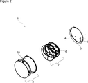
Figure 2 - is the exploded view of the door of the laundry washing and/or drying machine of the present invention.
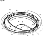
Figure 3 - is the perspective view of the embodiment of the present invention wherein the first door group and the second door group are connected to each other.
Figure 4 - is the view of detail A in Figure 3.
The elements illustrated in the figures are numbered as follows:
- Laundry washing and/or drying machine
- Opening
- Body
- Housing
- First door group
- Transparent element
- Second door group
- Third door group
- Hinge group
- Handle
- Door
- Stopper wall
- Tab
- First hole
- Second hole
- Locking member
The laundry washing and/or drying machine (1) comprises a body (3) which has a drum (not shown in figures) wherein the laundry to be treated is loaded and an opening (2) providing access into the drum; at least two mounting surfaces (not shown in figures) which are provided at different positions around the opening (2) on the body (3); and a door (11) having a first door group (5) which leakproofingly covers the opening (2) and which defines a housing (4) therein, a second door group (7) which is engaged with the first door group (5) by being placed into the housing (4) defined in the first door group (5) and which supports thereon at least one asymmetrical transparent element (6), a third door group (8) which is connected to the first door group (5) such that the second door group (7) remains therebetween, a hinge group (9) which is borne on the first door group (5), which is connected to a mounting surface on the body (3) from one end and which enables the first door group (5), the second door group (7) and the second door group (8) to make rotational movement around an axis as integrated with each other, and at least one handle (10) which is provided on the third door group (8) and which can be gripped by the user so as to allow the user to apply a pulling force. In the laundry washing and/or drying machine (1), the laundry to be washed and/or dried is loaded into the drum and is treated with water and/or air in the drum, thus performing the laundry washing and/or drying process. When a pulling or pushing force is applied onto the door (11) preferably by means of the handle (10), the door (11) makes a rotational movement around the axis of the hinge group (9) and opens to provide access into the drum by means of the opening (2) or is closed to prevent access into the drum. The door (11) comprises the first door group (5) which leakproofingly covers the opening (2) in the closed position, the second door group (7) which is placed into the housing (4) provided in the first door group (5) and the third door group (8) which is joined with the first door group (5) such that the second door group (7) remains therebetween. In the preferred embodiment of the present invention, the first door group (5), the second door group (7) and the third door group (8) are almost circular. By connecting the third door group (8) to the first door group (5), the components within the first door group (5) are not visible from the outside, thus improving the appearance aesthetically. At least one transparent element (6) enabling the user to view the inside of the drum is provided on the second door group (7), and said transparent element (6) is glass in the preferred embodiment of the present invention. The transparent element (6) has an asymmetrical structure so as to enable the water and/or air to be guided into the drum in the most efficient manner when the water and/or air used for washing and/or drying the laundry in the drum impacts on the transparent element (6). Therefore, in order to ensure an efficient washing and/or drying process in the drum, the position of the transparent element (6) with respect to the opening (2) must preferably remain as determined by the producer and not be changed.
In the laundry washing and/or drying machine (1), the second door group (7) is connected to the first door group (5) in at least two positions, that is a first position and a second position, in the housing (4) with respect to the first door group (5) and the third door group (8) mounted to the first door group (5). When the opening, hence closing, direction of the door (11) is desired to be changed, after the hinge group (9) is detached from the first mounting surface so as to disconnect the door (11) from the body (3), in an embodiment of the present invention, the first door group (5) and hence the third door group (8) connected to the first door group (5) are kept fixed and the second door group (7), which is already in the first position with respect to the first door group (5) and the third door group (8), is rotated in the housing (4) so as to be shifted to the second position. Since the position of the transparent element (6) supported by the second door group (7) changes when the second door group (7) shifts to the second position in the housing (4) as a result of the rotational movement, the door (11) is placed onto the opening (2) such that the position of the transparent element (6) with respect to the opening (2) remains the same as the initial situation, in other words, the door (11) is almost reversed and placed onto the opening (2) and then the hinge group (9) is connected to the second mounting surface, thus completing the connection of the door (11) to the body (3). In another embodiment of the present invention, when the opening direction of the door (11) is desired to be changed, the hinge group (9) is detached from the first mounting surface so as to disconnect the door (11) from the body (3), the second door group (7) is kept fixed, and the first door group (5) and hence the third door group (8) connected to the first door group (5) are rotated with respect to the second door group (7), and as a result of this rotational movement, the second door group (7) which is already in the first position with respect to the first door group (5) and the third door group (8) shifts to the second position. In this embodiment, since the second door group (7) does not move, the transparent element (6) does not move, either, and the door (11) is placed onto the opening (2) in the second position which is achieved by rotating the first door group (5) and hence the third door group (8) connected to the first door group (5) with respect to the second door group (7), and the hinge group (9) is connected to the second mounting surface, thus completing the connection of the door (11) to the body (3). Thus, without disconnecting the first door group (5) and the third door group (8) from each other and detaching the hinge group (9) from the point where the same is borne on the first door group (5), only by rotating the second door group (7) with respect to the first door group (5) and the third door group (8) which are connected to each other or rotating the first door group (5) and the third door group (8) which are connected to each other with respect to the second door group (7), the door (11), which previously opens to the right, is easily enabled to open to the left or the door (11), which previously opens to the left, is easily enabled to open to the right.
In an embodiment of the present invention, the laundry washing and/or drying machine (1) comprises at least two stopper walls (12) which are provided in the first door group (5) and at least one tab (13) which is provided on the second door group (7), which extends outwards from the second door group (7) and which enables the second door group (7) to be in the first position with respect to the first door group (5) upon contacting a first stopper wall (12) and enables the second door group (7) to be in the second position with respect to the first door group (5) upon contacting a second stopper wall (12). In other words, when the tab (13) contacts the first stopper wall (12), the second door group (8) is enabled to be in the first position in the housing (4) with respect to the first door group (5) and the third door group (8), and when the tab (13) contacts the second stopper wall (12), the second door group (7) is enabled to be in the second position in the housing (4) with respect to the first door group (5) and the second door group (8). In this embodiment, when the opening, hence closing, direction of the door (11) is desired to be changed, after the hinge group (9) is detached from the first mounting surface so as to disconnect the door (11) from the body (3), in an embodiment of the present invention, the first door group (5) and hence the third door group (8) connected to the first door group (5) are kept fixed and the second door group (7) is rotated in the housing (4) such that the tab (13), which already contacts the first stopper wall (12), starts to contact the second stopper wall (12). Since the position of the transparent element (6) supported by the second door group (7) changes when the second door group (7) shifts to the second position in the housing (4) as a result of the rotational movement, the door (11) is placed onto the opening (2) such that the position of the transparent element (6) with respect to the opening (2) remains the same as the initial situation, in other words, the door (11) is almost reversed and placed onto the opening (2) and then the hinge group (9) is connected to the second mounting surface, thus completing the connection of the door (11) to the body (3). In another embodiment of the present invention, when the opening direction of the door (11) is desired to be changed, the hinge group (9) is detached from the first mounting surface so as to disconnect the door (11) from the body (3), the second door group (7) is kept fixed, and the first door group (5) and hence the third door group (8) connected to the first door group (5) are rotated with respect to the second door group (7) until the tab (13), which already contacts the first stopper wall (12), starts to contact the second stopper wall (12). In this embodiment, since the second door group (7) does not move, the transparent element (6) does not move, either, and the door (11) is placed onto the opening (2) in the position which is achieved by rotating the first door group (5) and hence the third door group (8) connected to the first door group (5) with respect to the second door group (7), and the hinge group (9) is connected to the second mounting surface, thus completing the connection of the door (11) to the body (3). Thus, without disconnecting the first door group (5) and the third door group (8) from each other and detaching the hinge group (9) from the point where the same is borne on the first door group (5), only by rotating the second door group (7) with respect to the first door group (5) and the third door group (8) which are connected to each other or rotating the first door group (5) and the third door group (8) which are connected to each other with respect to the second door group (7), the door (11), which previously opens to the right, is easily enabled to open to the left or the door (11), which previously opens to the left, is easily enabled to open to the right.
In a particular embodiment of the present invention, the first door group (5) comprises two stopper walls (12) and the second door group (7) comprises two tabs (13). In this embodiment of the present invention, when the second door group (7) is in the first position in the housing (4), one of the tabs (13) contacts a first stopper wall (12) while the other tab (13) does not contact any stopper wall (12), remaining unattached When in order to change the opening direction of the door (11) the second door group (7) is rotated with respect to the first door group (5) and the third door group (8) which are connected to each other or the first door group (5) and the third door group (8) which are connected to each other are rotated with respect to the second door group (7), the second door group (7) shifts to the second position in the housing (4), and in this second position, the tab (13), which contacts the first stopper wall (12) in the first position, does not contact any stopper wall (12), remaining unattached while the other tab (13) does not contact the second stopper wall (12), remaining unattached. In this embodiment of the present invention, by using two tabs (13) and two stopper walls (12), the first position and the second position of the second door group (7) in the housing can be more precisely determined.
In an embodiment of the present invention, the tab (13) comprises at least one first hole (14), and the first door group (5) comprises at least two second holes (15), one aligning with the first hole (14) on the tab (13) when the second door group (7) is in the first position and the other aligning with the same when the second door group (7) is in the second position and which enable the first door group (5) and the second door group (7) to be fixed to each other by means of a connection member passing therethrough. In this embodiment, by fixing the second door group (7) to the first door group (5) by means of a connection member, preferably a screw, when the second door group (7) is in the first position and the second position, the second door group (7) is prevented from making unintentional rotational movement with respect to the first door group (5) and the third door group (8) which are connected to each other or the first door group (5) and the third door group (8) which are connected to each other are prevented from making unintentional rotational movement with respect to the second door group (7). In this embodiment, when the opening direction of the door (11) is desired to be changed, the hinge group (9) is detached from the first mounting surface so as to disconnect the door (11) from the body (3), and then the connection member passing through the relevant holes (14, 15) is taken out of the holes (14, 15). Thus, as a result of the rotational movement performed by allowing the second door group (7) to make rotational movement with respect to the first door group (5) and the third door group (8) which are connected to each other or allowing the first door group (5) and the third door group (8) which are connected to each other to make rotational movement with respect to the second door group (7), the second door group (7) is shifted from the first position to the second position or from the second position to the first position in the housing (4). Afterwards, said connection member is again passed through the relevant holes (14, 15), the second door group (7) and the first door group (5) are fixed to each other so as not move with respect to each other. In the preferred embodiment of the present invention, the connection member is passed through the first hole (14) and the second hole (15) or taken out of said holes (14, 15) which are aligned with each other at the side of the first door group (5) not facing the second door group (7), hence the third door group (8). Thus, the need for disconnecting the first door group (5) and the third door group (8) from each other while the connection member is passed through the first hole (14) and the second hole (15) or taken out of said holes (14, 15) which are aligned with each other is eliminated.
In an embodiment of the present invention, the first door group (5) comprises at least one locking member (15) which fixes the second door group (7) into the housing (4) so as to prevent the second door group (7) positioned in the housing (4) from moving towards the third door group (8). Thus, by allowing the second door group (7) only to rotate in the housing (4), the second door group (7) is prevented from rotating in the direction of said rotational axis by means of the locking member (15), and from unintentionally dislodging from the housing (4).
By means of the present invention, the opening, hence closing, direction of the door (11) which provides or prevents access into the drum in the laundry washing and/or drying machine (1) is changed by rotating the second door group (7) with respect to the first door group (5) and the third door group (8) which are connected to each other or rotating the first door group (5) and the third door group (8) which are connected to each other with respect to the second door group (7) without disconnecting the first door group (5) and the third door group (8) from each other, and thus enabling even inexperienced users to easily and quickly change the opening direction of the door (11).
Claims (5)
- A laundry washing and/or drying machine (1) comprising a body (3) which has a drum wherein the laundry to be treated is loaded and an opening (2) providing access into the drum; at least two mounting surfaces which are provided at different positions around the opening (2) on the body (3); and a door (11) having a first door group (5) which leakproofingly covers the opening (2) and which defines a housing (4) therein, a second door group (7) which is engaged with the first door group (5) by being placed into the housing (4) defined in the first door group (5) and which supports thereon at least one asymmetrical transparent element (6), a third door group (8) which is connected to the first door group (5) such that the second door group (7) remains therebetween, a hinge group (9) which is borne on the first door group (5), which is connected to a mounting surface on the body (3) from one end and which enables the first door group (5), the second door group (7) and the second door group (8) to make rotational movement around an axis as integrated with each other, and at least one handle (10) which is provided on the third door group (8) and which can be gripped by the user so as to allow the user to apply a pulling force, characterized by the second door group (7) which is connected to the first door group (5) in at least two positions, that is a first position and a second position, in the housing (4) with respect to the first door group (5) and the third door group (8) mounted to the first door group (5).
- A laundry washing and/or drying machine (1) as in Claim 1, characterized by at least two stopper walls (12) which are provided in the first door group (5) and at least one tab (13) which is provided on the second door group (7), which extends outwards from the second door group (7) and which enables the second door group (7) to be in the first position with respect to the first door group (5) upon contacting a first stopper wall (12) and enables the second door group (7) to be in the second position with respect to the first door group (5) upon contacting a second stopper wall (12).
- A laundry washing and/or drying machine (1) as in Claim 2, characterized by two stopper walls (12) which are provided in the first door group (5) and two tabs (13) which are provided on the two door group (7).
- A laundry washing and/or drying machine (1) as in Claim 2 or 3, characterized by the tab (13) comprising at least one first hole (14), and the first door group (5) comprising at least two second holes (15), one aligning with the first hole (14) on the tab (13) when the second door group (7) is in the first position and the other aligning with the same when the second door group (7) is in the second position and which enable the first door group (5) and the second door group (7) to be fixed to each other by means of a connection member passing therethrough.
- A laundry washing and/or drying machine (1) as in any one of the above claims, characterized by at least one locking member (15) which fixes the second door group (7) into the housing (4) so as to prevent the second door group (7) positioned in the housing (4) from moving towards the third door group (8).
Applications Claiming Priority (2)
| Application Number | Priority Date | Filing Date | Title |
|---|---|---|---|
| TR201820406 | 2018-12-25 | ||
| TR2018/20406 | 2018-12-25 |
Publications (1)
| Publication Number | Publication Date |
|---|---|
| WO2020135984A1 true WO2020135984A1 (en) | 2020-07-02 |
Family
ID=68806756
Family Applications (1)
| Application Number | Title | Priority Date | Filing Date |
|---|---|---|---|
| PCT/EP2019/083573 Ceased WO2020135984A1 (en) | 2018-12-25 | 2019-12-04 | A laundry washing and/or drying machine comprising a door with changeable opening direction |
Country Status (1)
| Country | Link |
|---|---|
| WO (1) | WO2020135984A1 (en) |
Citations (5)
| Publication number | Priority date | Publication date | Assignee | Title |
|---|---|---|---|---|
| WO2003004754A1 (en) * | 2001-07-05 | 2003-01-16 | Arçelik, A. S. | Washing machine door |
| EP2147996A1 (en) * | 2008-07-23 | 2010-01-27 | Electrolux Home Products Corporation N.V. | Reversible door assembly for a front loading laundry treating machine |
| DE102011078920A1 (en) * | 2011-07-11 | 2013-01-17 | Bosch-Siemens Hausgeräte Gmbh | Loading door for a laundry treatment machine |
| WO2015144236A1 (en) | 2014-03-28 | 2015-10-01 | Arcelik Anonim Sirketi | Improved reversible door for household appliance |
| EP3339499A1 (en) * | 2016-12-22 | 2018-06-27 | Electrolux Appliances Aktiebolag | Laundry dryer equipped with a door assembly |
-
2019
- 2019-12-04 WO PCT/EP2019/083573 patent/WO2020135984A1/en not_active Ceased
Patent Citations (5)
| Publication number | Priority date | Publication date | Assignee | Title |
|---|---|---|---|---|
| WO2003004754A1 (en) * | 2001-07-05 | 2003-01-16 | Arçelik, A. S. | Washing machine door |
| EP2147996A1 (en) * | 2008-07-23 | 2010-01-27 | Electrolux Home Products Corporation N.V. | Reversible door assembly for a front loading laundry treating machine |
| DE102011078920A1 (en) * | 2011-07-11 | 2013-01-17 | Bosch-Siemens Hausgeräte Gmbh | Loading door for a laundry treatment machine |
| WO2015144236A1 (en) | 2014-03-28 | 2015-10-01 | Arcelik Anonim Sirketi | Improved reversible door for household appliance |
| EP3339499A1 (en) * | 2016-12-22 | 2018-06-27 | Electrolux Appliances Aktiebolag | Laundry dryer equipped with a door assembly |
Similar Documents
| Publication | Publication Date | Title |
|---|---|---|
| US12227891B2 (en) | Washing machine | |
| EP3189179B1 (en) | Washing machine | |
| AU2010206038B2 (en) | Washing machine | |
| US8844328B2 (en) | Door of a household electrical appliance | |
| US9650737B2 (en) | Laundry treating apparatus | |
| EP2147996B1 (en) | Reversible door assembly for a front loading laundry treating machine | |
| US9873973B2 (en) | Washing machine | |
| AU2017380401B2 (en) | Washing machine | |
| EP2816151B1 (en) | Washing machine | |
| US9790633B2 (en) | Laundry treating apparatus | |
| JP3801167B2 (en) | Drum washing machine | |
| US10865513B2 (en) | Washing machine and home appliance | |
| KR101706969B1 (en) | Laundry treating apparatus and door assembly thereof | |
| KR101706968B1 (en) | Laundry treating apparatus and door assembly thereof | |
| EP3899126B1 (en) | A laundry washing and/or drying machine comprising a hinge group | |
| JP2004105268A (en) | Drum type washing machine | |
| AU2011226929B2 (en) | Washing machine | |
| CA3052408C (en) | Washing machine | |
| KR20040046917A (en) | The door's hinge assembly of a druma washer | |
| KR20160084326A (en) | Laundry treating apparatus and door assembly thereof | |
| KR20000003809U (en) | washer |
Legal Events
| Date | Code | Title | Description |
|---|---|---|---|
| 121 | Ep: the epo has been informed by wipo that ep was designated in this application |
Ref document number: 19816280 Country of ref document: EP Kind code of ref document: A1 |
|
| NENP | Non-entry into the national phase |
Ref country code: DE |
|
| 122 | Ep: pct application non-entry in european phase |
Ref document number: 19816280 Country of ref document: EP Kind code of ref document: A1 |