WO2020129752A1 - オントロジー作成装置、方法およびプログラム - Google Patents
オントロジー作成装置、方法およびプログラム Download PDFInfo
- Publication number
- WO2020129752A1 WO2020129752A1 PCT/JP2019/048281 JP2019048281W WO2020129752A1 WO 2020129752 A1 WO2020129752 A1 WO 2020129752A1 JP 2019048281 W JP2019048281 W JP 2019048281W WO 2020129752 A1 WO2020129752 A1 WO 2020129752A1
- Authority
- WO
- WIPO (PCT)
- Prior art keywords
- class
- ontology
- instance
- unit
- subject
- Prior art date
- Legal status (The legal status is an assumption and is not a legal conclusion. Google has not performed a legal analysis and makes no representation as to the accuracy of the status listed.)
- Ceased
Links
Images







Classifications
-
- G—PHYSICS
- G06—COMPUTING OR CALCULATING; COUNTING
- G06F—ELECTRIC DIGITAL DATA PROCESSING
- G06F40/00—Handling natural language data
- G06F40/30—Semantic analysis
-
- G—PHYSICS
- G06—COMPUTING OR CALCULATING; COUNTING
- G06F—ELECTRIC DIGITAL DATA PROCESSING
- G06F16/00—Information retrieval; Database structures therefor; File system structures therefor
- G06F16/30—Information retrieval; Database structures therefor; File system structures therefor of unstructured textual data
- G06F16/36—Creation of semantic tools, e.g. ontology or thesauri
- G06F16/367—Ontology
-
- G—PHYSICS
- G06—COMPUTING OR CALCULATING; COUNTING
- G06F—ELECTRIC DIGITAL DATA PROCESSING
- G06F40/00—Handling natural language data
- G06F40/20—Natural language analysis
- G06F40/237—Lexical tools
-
- G—PHYSICS
- G06—COMPUTING OR CALCULATING; COUNTING
- G06F—ELECTRIC DIGITAL DATA PROCESSING
- G06F8/00—Arrangements for software engineering
- G06F8/10—Requirements analysis; Specification techniques
Definitions
- the embodiment of the present invention relates to an ontology creating device, method, and program.
- Ontology has been playing an active role as a tool capable of expressing meanings and systems not only in the WEB field but also in various fields including the IoT (Internet of Things).
- RDF Resource Description Framework
- JSON-LD Joint Description Framework
- FIG. 14 is a diagram illustrating an example of ontology construction in IoT.
- IoT platform that uses an ontology.
- a conversion proxy is provided between a common platform (PF) that is provided in common by each business operator as a data provider and exchanges data with applications and another standard PF/Device.
- This conversion procedure exchanges data between the common platform (PF) and another standard PF/Device using ontology data in which a data structure common to each standard is described.
- the IoT device (Device) transmits and receives data via the service.
- a DataPoint is defined under the service.
- a hierarchical relationship is defined by using a “ConsistsOf” field to represent a child device and a child service.
- the class (Device) and the class "Service” are associated with the ObjectProperty "hasService”
- the class “Service” and the class “OutputDataPoint” are associated with the ObjectProperty “hasOutputDataPoint”
- the class “Service , And the class “InputDataPoint” are related by ObjectProperty “hasInputDataPoint”.
- the class “Service” and the literal “API (Application Programming Interface)” are associated with each other by the DatatypeProperty “Protocol:hasAPI”.
- ObjectProperty indicates the relationship between classes and the relationship between instances that belong to the class.
- Constraint (1) Classes are limited to Thing/Device/Service/DataPoint, etc.
- Constraint (2) ObjectProperty between classes is constant. For example, ⁇ Device, hasService, Service ⁇ is appropriate, but ⁇ Device, hasInputDataPoint, InputDataPoint ⁇ is not.
- Constraint (3) Datatype Property that can be assigned to each class is constant. For example, ⁇ Service, hasAPI, API ⁇ is appropriate, but ⁇ Device, hasAPI, API ⁇ is not.
- the conventional ontology construction tool newly creates a class such as Device/Service, Instance, ObjectProperty, and DatatypeProperty.
- the ontology building tool adds a label which is a class description document.
- the label of the Device class can be defined as "device that generates data and receives a command”.
- the relationships between classes and between classes and instances are defined using properties, and the results are output. In such a procedure, the above problems exist.
- the present invention has been made in view of the above circumstances, and an object thereof is to simplify an ontology creation related to data exchange and to prevent an erroneous creation ontology creation device, method, and To provide a program.
- a first aspect of an ontology creating device is a first storage device in which information representing a definition of an ontology class candidate is stored;
- a first selection unit that receives an input operation for selecting a class from the ontology class candidates, which is performed based on information that represents a definition stored in the storage device, and a class as an object and a class as a subject.
- a second storage device that stores information that represents the definition of the property that indicates the connection relationship of the class, and a selection that is made by the first selection unit based on the information that represents the definition that is stored in the second storage device.
- An acquisition unit that acquires a candidate of a class as a subject for the object when the object is a class, and the first candidate performed based on the candidate of a class as a subject acquired by the acquisition unit.
- the second selection unit that receives an input operation for selecting an instance belonging to the class as the subject of the object
- the first selection unit An instance belonging to the selected ontology class and a connection setting unit that sets a connection relationship between the instance selected by the second selection unit, the ontology class selected by the first selection unit, and The instance selected by the second selection unit, and the output unit that creates and outputs the ontology indicating the connection relationship set by the relationship setting unit, respectively.
- a second aspect of the ontology creating device is the third storage device according to the first aspect, wherein the information indicating the definition of the candidate of the property indicating the relationship between the class and the literal is stored, and the third storage device.
- a second acquisition unit that acquires a literal related to the class and an editing unit that receives an input operation related to the editing of the literal acquired by the second acquisition unit are further provided.
- a third aspect of the ontology creating device of the present invention is, in the first aspect, the output unit, information indicating a relationship between a class of the ontology selected by the first selecting unit and an instance belonging to the class, Information indicating a relationship between instances belonging to an instance group including an instance belonging to the ontology class selected by the first selecting unit and an instance selected by the second selecting unit, and an instance belonging to the instance group And at least one piece of information indicating the relation between the literal and the literal is generated, and the generated information is converted into an ontology and output.
- the literal acquired by the second acquisition unit is a data type of an instance belonging to the instance group.
- One aspect of the ontology creating method performed by the ontology creating device is information stored in the first storage device, which is based on the information indicating the definition of the candidate of the ontology class,
- the class is selected by an input operation, and is selected based on the information stored in the second storage device, which is the information indicating the definition of the property indicating the connection relationship between the class as the object and the class as the subject.
- a class is an object
- acquiring a candidate for a class as a subject for the object based on the acquired candidate for a class as a subject, when the selected class is an object,
- an instance belonging to a class as a subject for the object By selecting an instance belonging to a class as a subject for the object by an input operation, an instance belonging to the class of the selected ontology, and a connection relationship between the selected instances are set, and an instance of the selected ontology is set.
- An ontology indicating the class, the selected instance, and the set connection relationship is created and output.
- One aspect of the ontology creation processing program is to cause a processor to function as each unit of the ontology creation device according to any one of the first to fourth aspects.
- a class is selected by an input operation based on the information indicating the definition of the candidate for the ontology class, and the class is selected as the object and the subject.
- the candidate of the class as the subject of the object is acquired and selected from the acquired candidates. Select the instance belonging to the class as the subject when the specified class is the object by input operation, set the connection relationship between the selected class and instances, and select the selected class, instance and the set connection relationship Since an ontology indicating each of the above is generated and output, it is possible to simplify the ontology generation and prevent erroneous generation.
- the instance group is related to the class to which the instance group belongs based on the information indicating the definition of the property candidate indicating the relationship between the class and the literal. Since the literal can be acquired and the literal can be edited, the user can prevent erroneous recognition of the editable literal.
- the ontology includes information indicating the relationship between the class and the instance, information indicating the relationship between the instances, and information indicating the relationship between the instance and the literal. Since it is converted to and output, an ontology based on an appropriately selected or edited class, instance, or literal can be output.
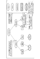
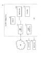
- FIG. 1 is a diagram showing an example of a procedure performed by an ontology creating device according to an embodiment of the present invention.
- FIG. 2 is a diagram showing an example of a screen configuration of a constrained ontology creation GUI.
- FIG. 3 is a diagram showing a configuration example of an ontology creation GUI system (system) according to an embodiment of the present invention.
- FIG. 4 is a diagram illustrating an example of a workflow for creating a new instance.
- FIG. 5 is a diagram showing an example of a DatatypeProperty setting subflow.
- FIG. 6 is a diagram showing an example of the owl output subflow.
- FIG. 7 is a diagram illustrating an example of creating an ontology.
- FIG. 1 is a diagram showing an example of a procedure performed by an ontology creating device according to an embodiment of the present invention.
- FIG. 2 is a diagram showing an example of a screen configuration of a constrained ontology creation GUI.
- FIG. 3 is a diagram showing
- FIG. 8 is a diagram illustrating an example of a GUI screen in which restrictions are placed on the instances that can be created.
- FIG. 9 is a diagram illustrating an example of the GUI screen in which the relationship between the instances is restricted.
- FIG. 10 is a diagram illustrating an example of a GUI screen in which a constraint is set in the DatatypeProperty of the instance.
- FIG. 11 is a diagram illustrating an example of a GUI screen in which a constraint is set in the DatatypeProperty of the instance.
- FIG. 12 is a diagram illustrating an example of ontology output.
- FIG. 13 is a block diagram showing an example of the hardware configuration of the ontology creation GUI system according to the embodiment of the present invention.
- FIG. 14 is a diagram illustrating an example of ontology construction in IoT.
- the ontology creating apparatus uses a GUI (Graphical User Interface) to create a ontology and create the ontology while creating the ontology. To simplify.
- GUI Graphic User Interface
- the system automatically selects the data type property (DatatypeProperty) that can be created for each instance by automatically referring to the relationship between the class and the property, which is the original design, and can be edited by the user. Put in a state. This also prevents the attributes from being erroneously created.
- DatatypeProperty data type property
- FIG. 1 is a diagram showing an example of a procedure performed by an ontology creating device according to an embodiment of the present invention.
- the ontology creating device according to an embodiment of the present invention differs from the conventional ontology building process in that the ontology is erroneously created by applying a constraint using the GUI when creating the ontology, and the ontology and the design are inconsistent. Can be effectively prevented.
- a class group, an instance, an ObjectProperty, and a DatatypeProperty are newly created, and the relationship between the class to which the label and the instance belong and the literal(API) are set, and the consistency is verified before output.
- This procedure is all performed by a user's operation (manual).
- a class group, ObjectProperty, and DatatypeProperty are prepared in advance by the GUI. Only classes with limited design are prepared here. Then, an instance is newly created by a user operation. Then, the ontology creating device automatically sets the relationship of the class to which the instance belongs, inherits the DatatypeProperty of the class to which the instance belongs, and automatically displays the corresponding literal edit screen. Then, the literal is set by the user operation, and the ontology creating device automatically sets the label and automatically outputs the label in real time.
- FIG. 2 is a diagram showing an example of a screen configuration of a constrained ontology creation GUI.
- classes (Device, Service, InputDataPoint, OutputDataPoint, SimpleDataType) prepared in advance by the GUI are displayed.
- An ontology diagram can be created by combining the displayed classes.
- OWL Web Ontology Language
- JSON are automatically created from the created ontology diagram.
- FIG. 3 is a diagram showing a configuration example of an ontology creation GUI system according to an embodiment of the present invention.
- the function of the ontology creation GUI system 10 shown in FIG. 3 includes a processor such as a CPU (Central Processing Unit) that executes a program, a storage medium such as a RAM (Random Access Memory) and a ROM (Read Only Memory), and a keyboard. It can be realized by using an input device such as and a display device such as a display.
- a processor such as a CPU (Central Processing Unit) that executes a program
- a storage medium such as a RAM (Random Access Memory) and a ROM (Read Only Memory)
- a keyboard such as a keyboard
- an input device such as and a display device such as a display.
- the ontology creation GUI system 10 includes a class selection unit 11 (which may be referred to as A and class selection unit), an ObjectProperty determination unit 12 (which may be referred to as B and ObjectProperty determination unit), and a relationship setting unit 13 (C. , which may be referred to as a relationship setting unit). Furthermore, the ontology creation GUI system 10 includes a DatatypeProperty determination unit 14 (sometimes referred to as D, DatatypeProperty determination unit), a literal setting unit 15 (sometimes referred to as E, literal setting unit), and an owl output unit 16. (Sometimes referred to as an F, owl output section).
- the class selection unit 11 includes a class definition storage unit (sometimes referred to as a storage unit (storage device) X) 11a.
- the ObjectProperty determination unit 12 has an ObjectProperty information storage unit (sometimes referred to as a storage unit Y) 12a.
- the relationship setting unit 13 has a relationship information storage unit (may be referred to as a storage unit Z) 13a.
- the DatatypeProperty determination unit 14 has a DatatypeProperty information storage unit (sometimes referred to as a storage unit U) 14a.
- the literal setting unit 15 has a literal information storage unit (may be referred to as a storage unit V) 15a.
- the owl output unit 16 has a json/owl information storage unit (sometimes referred to as a storage unit W) 16a.
- the information stored in the storage units X, Y, U is set in advance.
- the storage unit X stores the following design class groups in advance.
- the design class group is information that represents the definition of ontology class candidates.
- Design object property groups which are information representing the definition of properties indicating the connection relationship between the class as the object and the class as the subject, for example, (1) to (4) below are stored in advance.
- It Design Object Property group ⁇ OP 1 , OP 2 ,..., OP n ⁇ : (1) OP 1 :hasService: (Subject) Device ⁇ (Object) Service (2) OP 2 :hasInputDataPoint: (subject) Service ⁇ (object) InputDataPoint (3) OP 3 :hasOutputDataPoint: (Subject) Service ⁇ (Object) OutputDataPoint (4) OP 3 :hasDatatype: (Subject) InputDataPoint ⁇ (Object) SimpleDataType
- Design DatatypeProperty group which is information indicating the definition of a property candidate, for example, the following (1) to (5) is stored in advance. This property indicates the relationship between the class and literal.
- Design Datatype Property group ⁇ DP 1 , DP 2 ,..., DP n ⁇ : (1) DP 1 :rdfs:about: (subject) All classes ⁇ literal (2) DP 2 :hasAPI: Subject Service
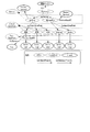
- FIG. 4 is a diagram illustrating an example of a workflow for creating a new instance.
- the class selection unit 11 displays the class C select to which the newly created instance belongs in the design class group displayed in the area on the right side of the GUI screen (creation screen shown in FIG. 2). A selection is made from ⁇ C 1 , C 2 ,..., C n ⁇ according to a user operation, and the selected result is stored in the storage unit X (S11).
- the class selection unit 11 newly creates the instance I created of C select selected in S11 in the area on the left side of the GUI screen by a user's input operation or automatically (S12).
- the ObjectProperty determination unit 12 selects the ObjectProperty group OPS select whose C select selected in S11 is the object (Object) from the design ObjectProperty group ⁇ OP 1 , OP 2 ,..., OP n ⁇ stored in the storage unit Y. It is acquired (S13).
- the ObjectProperty determination unit 12 acquires the class group SS select that is the subject (Subject) defined by each ObjectProperty that constitutes the OPS select acquired in S13 (S14). This acquisition result is a candidate for a class that can be set as a subject for the object when the object selected is the class selected in S11.
- the relationship setting unit 13 determines whether or not the instance belonging to the class group SS select acquired in S13 exists in the area on the left side of the GUI screen (S15). If this instance exists (Yes in S15), the relationship setting unit 13 is an instance displayed in the area on the left side of the GUI screen and belonging to the class group SS select acquired in S13 ⁇ Parent 1 , Parent 1 , ..., Parent n ⁇ are all highlighted and displayed, and the instances can be connected according to the user's operation.
- the relationship setting unit 13 links the selected instance Parent select and the instance I created created in S12. Then, a line segment showing this connection is drawn on the GUI screen.
- the relationship setting unit 13 assigns a property (ObjectProperty) OP select (OP select ⁇ OPS select ) indicating the relationship between these instances to each linked instance, and stores this property in the storage unit Z ( S18). After S18, or if there is no instance in S15 (No in S15), the DatatypeProperty setting subflow (S20:S21 to S23) and the owl generation subflow (S30:S31 to S35) are executed, and the process ends.
- OP select OP select ⁇ OPS select
- FIG. 5 is a diagram illustrating an example of a DatatypeProperty setting subflow.
- the DatatypeProperty determination unit 14 stores in the storage unit U the datatypeProperty group related to the instance to which the instance I editing created in S12 belongs and the instance selected in S17. It is acquired from the design Datatype Property group ⁇ DP 1 , DP 2 ,..., DP n ⁇ (S21). This acquisition result corresponds to the literals related to the instance belonging to the class selected in S11 and the instance selected in S17, respectively.
- the DatatypeProperty determination unit 14 displays on the GUI screen the edit window of the literal defined by the DatatypeProperty group acquired in S21 (S22). On this screen, the user can edit the literal by input operation.
- the literal setting unit 15 stores information (I editing , DP editing , literal) in which the I editing created in S12, the edited literal, and the DP editing that is the Datatype Property corresponding to this literal are associated with each other. It is stored in the section V (S23). This ends the DatatypeProperty setting subflow.
- FIG. 6 is a diagram showing an example of the owl output subflow.
- the owl output unit 16 displays, from the storage units X, Y, Z, U, V, an instance group ⁇ I 1 , I belonging to various classes displayed in the area on the left side of the GUI screen. 2 ,..., I n ⁇ are acquired (S31).
- This instance group includes the instances belonging to the class acquired in S11 and the instances selected in S17.
- the owl output unit 16 outputs information indicating the relationship between the instance and the class to which the instance belongs, for each instance that constitutes the instance group ⁇ I 1 , I 2 ,..., I n ⁇ acquired in S31.
- I i , rafs:subClassof, C i ) is created (S32).
- the owl output unit 16 creates information (I i , OP W , I j ) indicating the relationship between the instances that form the instance group ⁇ I 1 , I 2 ,..., I n ⁇ acquired in S31. (S33). This creation result indicates the relationship between two instances belonging to the instance group including the instance belonging to the class selected in S11 and the instance selected in S17.
- the owl output unit 16 provides information (I i , DP) indicating the relationship between the instance and literal for each instance that constitutes the instance group ⁇ I 1 , I 2 ,..., I n ⁇ acquired in S31. W , I j ) is created (S34). This creation result shows the relationship between the instances belonging to the above instance group and the literals.
- the owl output unit 16 converts each information created in S32 to S34 into an owl format (format), stores it in the storage unit W, and outputs it to the outside (S35). This ends the owl output subflow.
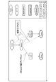
- FIG. 7 is a diagram illustrating an example of creating an ontology.
- the instances “getData” and “ManageDev” belong to the class "Service”
- the instances “Temperature”, “Humidity” and “CO2” belong to the class “OutputDataPoint”
- the instance “Interval” and "Switch” belongs to the class "InputDataPoint”.
- the instance “EnvSensor” is associated with the instances “getData” and “ManageDev” by the ObjectProperty “hasService”.
- the instance “getData” is associated with the instances “temperature”, “humidity” and “CO2” by the ObjectProperty “hasOutputDataPoint”.
- the instance “ManageDev” is associated with the instances “Interval” and “Switch” by the ObjectProperty "hasInputDataPoint”.
- the instance “EnvSensor” is associated with the literal “environment sensor” by the DatatypeProperty “is-a”.
- the instance “ManageDev” is associated with the literal “Sensor/Service1” by the DatatypeProperty “hasAPI”.
- the instance “getData” is associated with the literal “Sensor/Service2" by the DatatypeProperty “hasAPI”.
- the instance “temperature” is associated with the literal “DATA:arg(argument)1” by the DatatypeProperty “hasAPI”.
- Instance "humidity” is associated with literal “DATA:arg2” by DatatypeProperty “hasAPI”.
- Instance "CO2” is associated with literal “DATA:arg3” by DatatypeProperty “hasAPI”.
- Instance “Interval” is associated with literal “DATA:arg4” by DatatypeProperty “hasAPI”.
- the instance “Switch” is associated with the literal “DATA:arg5" by the DatatypeProperty “hasAPI”.
- Instances "temperature”, “humidity", “CO2”, “Interval” and “Switch” are associated with literal “float” by DatatypeProperty “hasDatatype”.
- FIG. 8 is a diagram illustrating an example of a GUI screen in which restrictions are placed on the instances that can be created.
- the user uses the class candidates “Device”, “Service”, “InputDataPoint”, OutputDataPoint”, and “SimpleDataType”, which are candidates prepared in the area on the right side of the GUI screen.
- an instance can be created (drawn) in the area on the left side of the GUI screen.
- the following (1) to (7) are created.
- FIG. 9 is a diagram illustrating an example of the GUI screen in which the relationship between the instances is restricted.
- the line segment indicating the relationship between the instances can be drawn on the GUI screen only as the line segment indicating the relationship according to the design ObjectProperty group.
- a line segment indicating a relationship that does not follow the design ObjectProperty group cannot be drawn on the GUI screen, and the relationship setting unit 13 cannot set the corresponding relationship.
- one line segment indicating the relationship may be drawn between the instance belonging to the class “Service” and the instance belonging to the class “InputDataPoint” on the GUI screen. However, no more than one line segment can be drawn between the same instances.
- FIG. 10 and FIG. 11 are diagrams illustrating an example of a GUI screen in which the DatatypeProperty of the instance is restricted.
- the Datatype Property that can be set in the instance is limited to “NAME: rename” and “DELETE: delete”.
- the DatatypeProperty that can be set in the instance is “NAME: rename”, “DELETE: Restricted to "Delete”, “hasAPI” and “storage status (storeTimeseries (storage of time series data), onDemand (data is acquired by request from application) and onDemandTS (time series data is acquired by request from application))” It
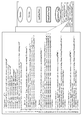
- FIG. 12 is a diagram illustrating an example of ontology output.
- the EnvSensor sensor classes and instances shown in Fig. 7 are drawn on the GUI screen as shown in Fig. 8, as shown in Fig. 12, the CO2 sensor and the temperature
- An owl output unit 16 creates an OWL file (file) which is an ontology of a Light device having a sensor and an ON/OFF switch (switch).
- FIG. 13 is a block diagram showing an example of the hardware configuration of the ontology creation GUI system according to the embodiment of the present invention.
- the ontology creation GUI system 10 according to the above embodiment is configured by, for example, a server computer or a personal computer, and a hardware processor such as a CPU. It has 111A.
- a program memory 111B, a data memory 112, an input/output interface 113, and a communication interface 114 are connected to the hardware processor 111A via a bus 120.
- the communication interface 114 includes, for example, one or more wireless communication interface units, and enables transmission and reception of information with the communication network NW.
- the wireless interface for example, an interface adopting a low power wireless data communication standard such as wireless LAN (Local Area Network) is used.
- the input/output interface 113 is connected to an input device 30 and an output device 40 for an operator, which are attached to the ontology creation GUI system 10.
- the input/output interface 113 takes in operation data input by an operator through an input device 30 such as a keyboard, a touch panel, a touchpad, and a mouse, and outputs the output data to a liquid crystal or organic EL (Electro Luminescence) or the like is output to an output device 40 including a display device and displayed.
- the input device 30 and the output device 40 may be devices built in the ontology creation GUI system 10 and can communicate with the ontology creation GUI system 10 via a network NW.
- the input device and output device of the information terminal may be used.
- the program memory 111B is, as a non-transitory tangible storage medium, for example, a nonvolatile memory (non-volatile memory) such as an HDD (Hard Disk Drive) or an SSD (Solid State Drive) capable of writing and reading at any time, It is used in combination with a non-volatile memory such as a ROM (Read Only Memory), and stores programs necessary for executing various control processes according to an embodiment.
- a nonvolatile memory such as an HDD (Hard Disk Drive) or an SSD (Solid State Drive) capable of writing and reading at any time
- a non-volatile memory such as a ROM (Read Only Memory)
- ROM Read Only Memory
- the data memory 112 is, as a tangible storage medium, a combination of, for example, the above-mentioned nonvolatile memory and a volatile memory such as a RAM (Random Access Memory), and various processes are performed. It is used to store various data acquired and created in the process.
- a RAM Random Access Memory
- the ontology creation GUI system 10 is a processing function unit by software (classified as a class) such as a class selection unit 11, an ObjectProperty determination unit 12, a relationship setting unit 13, and a DatatypeProperty determination shown in FIG. It can be configured as a data processing device having a unit 14, a literal setting unit 15, and an owl output unit 16.
- the class definition storage unit 11a, the ObjectProperty information storage unit 12a, the relationship information storage unit 13a, the DatatypeProperty information storage unit 14a, the literal information storage unit 15a, and the json/owl information storage unit 16a are the same as the data memory 112 shown in FIG. It can be configured to be used. However, these storage units are not an indispensable component in the ontology creation GUI system 10, and for example, an external storage medium such as a USB (Universal Serial Bus) memory or a database server (database server) arranged in a cloud. ) Or the like may be provided in the storage device.
- USB Universal Serial Bus
- database server database server
- the processing function units in the class selecting unit 11, the ObjectProperty determining unit 12, the relationship setting unit 13, the DatatypeProperty determining unit 14, the literal setting unit 15, and the owl output unit 16 are all stored in the program memory 111B. It can be realized by causing the hardware processor 111A to read and execute the program. Note that some or all of these processing function units can be implemented in various other formats including integrated circuits such as application-specific integrated circuits (ASICs) or field-programmable gate arrays (FPGAs). May be realized.
- ASICs application-specific integrated circuits
- FPGAs field-programmable gate arrays
- the ontology creating device selects a class by an input operation based on the information indicating the definition of the candidate class of the ontology, and selects the class as the object and the class as the subject. Based on the information that represents the definition of the property that indicates the connection relationship, when the selected class is the object, a candidate for the class as the subject for the object is acquired, and selected based on the acquired candidate.
- the method described in each embodiment is, as a program (software means) that can be executed by a computer (computer), for example, a magnetic disk (floppy (registered trademark) disk (Floppy disk), hard disk, etc.), optical disk ( It can be stored in a recording medium such as a CD-ROM, a DVD, an MO, etc.), a semiconductor memory (ROM, RAM, a flash memory, etc.), or transmitted by a communication medium for distribution.
- the programs stored on the medium side also include setting programs for configuring software means (including not only execution programs but also tables and data structures) to be executed by the computer in the computer.
- a computer that realizes this device reads a program recorded in a recording medium, and if necessary, constructs software means by a setting program, and the operation is controlled by this software means to execute the processing described above.
- the recording medium referred to in the present specification is not limited to distribution, but includes a storage medium such as a magnetic disk or a semiconductor memory provided inside a computer or in a device connected via a network.
- the present invention is not limited to the above-described embodiment, and can be variously modified in an implementation stage without departing from the gist thereof. Further, the respective embodiments may be appropriately combined and implemented, in which case the combined effects can be obtained. Further, the above-described embodiment includes various inventions, and various inventions can be extracted by a combination selected from a plurality of disclosed constituent features. For example, even if some constituent elements are deleted from all the constituent elements shown in the embodiment, if the problem can be solved and the effect can be obtained, the structure in which the constituent elements are deleted can be extracted as the invention.
Landscapes
- Engineering & Computer Science (AREA)
- Theoretical Computer Science (AREA)
- General Engineering & Computer Science (AREA)
- Physics & Mathematics (AREA)
- General Physics & Mathematics (AREA)
- Computational Linguistics (AREA)
- Life Sciences & Earth Sciences (AREA)
- Animal Behavior & Ethology (AREA)
- Data Mining & Analysis (AREA)
- Databases & Information Systems (AREA)
- Health & Medical Sciences (AREA)
- Artificial Intelligence (AREA)
- Audiology, Speech & Language Pathology (AREA)
- General Health & Medical Sciences (AREA)
- Software Systems (AREA)
- Stored Programmes (AREA)
- Information Retrieval, Db Structures And Fs Structures Therefor (AREA)
- User Interface Of Digital Computer (AREA)
Abstract
一実施形態に係るオントロジー作成装置は、オントロジーのクラスの候補の定義を表す情報に基づいてクラスを選択するための入力操作を受け付ける第1の選択部と、目的語としてのクラスおよび主語としてのクラスの接続関係を示すプロパティの定義を表す情報に基づいて、選択されたクラスを目的語としたときの主語としてのクラスの候補を取得する取得部と、当該候補に基づいて、選択されたクラスを目的語としたときの主語としてのクラスに属するインスタンスを選択するための入力操作を受け付ける第2の選択部と、選択されたクラスに属するインスタンスと選択されたインスタンスとの間の接続関係を設定する関係設定部と、選択されたクラス、インスタンスおよび設定された接続関係をそれぞれ示すオントロジーを作成して出力する出力部とを有する。
Description
本発明の実施形態は、オントロジー作成装置、方法およびプログラムに関する。
近年、オントロジー(Ontology)はWEB分野だけでなく、IoT(Internet of Things)を含む様々な分野で意味および体系を表現可能であるツール(tool)として活躍している。
ところが、オントロジーが記述される言語(RDF(Resource Description Framework)、JSON-LD…)は手動により作成されることが困難な上、この言語が作成される際に、オントロジーが運用されるアプリケーションプログラム(application program)(アプリケーション、又はアプリ)に必要な制約(restriction)が適切に設けられることができない。
ところが、オントロジーが記述される言語(RDF(Resource Description Framework)、JSON-LD…)は手動により作成されることが困難な上、この言語が作成される際に、オントロジーが運用されるアプリケーションプログラム(application program)(アプリケーション、又はアプリ)に必要な制約(restriction)が適切に設けられることができない。
ここで、IoTにおけるオントロジー構築について説明する。図14は、IoTにおけるオントロジー構築の一例を説明する図である。
IoTデータ(data)の意味および体系を表現する手段として、オントロジーが利用されるIoTプラットフォーム(platform)がある。
IoTデータ(data)の意味および体系を表現する手段として、オントロジーが利用されるIoTプラットフォーム(platform)がある。
例えば、データ提供者としての各事業者に共通して設けられてアプリとの間でデータ交換を行なう共通プラットフォーム(PF)と他規格PF/Deviceとの間に変換プロクキ(Proxy)が設けられる。この変換プロクキは、各規格に共通するデータ構造が記述されたオントロジーデータを用いて、共通プラットフォーム(PF)と他規格PF/Deviceとの間でデータ交換を行なう。
ここでは、IoTデバイス(Device)はサービス(Service)経由でデータの送受信を行なうと仮定する。RESTfulインタフェース(interface)を有する異種規格では、サービスの下にDataPointが定義される。
また、複雑なIoTデバイスでは、「ConsistsOf」フィールド(field)が利用されて、子デバイスと子サービスとが表現されることによって、階層関係が定義される。
また、複雑なIoTデバイスでは、「ConsistsOf」フィールド(field)が利用されて、子デバイスと子サービスとが表現されることによって、階層関係が定義される。
例えば、クラス(class)「Device」とクラス「Service」との間はObjectProperty「hasService」で関連付けられ、クラス「Service」とクラス「OutputDataPoint」との間はObjectProperty「hasOutputDataPoint」で関連付けられ、クラス「Service」とクラス「InputDataPoint」との間はObjectProperty「hasInputDataPoint」で関連付けられる。
また、クラス「Service」とリテラル(literal)「API(Application Programming Interface(アプリケーションプログラミングインタフェース))」との間はDatatypeProperty「Protocol:hasAPI」で関連付けられる。ObjectPropertyは、クラス間の関係と、クラスに属するインスタンス(Instance)間の関係とを示す。
また、クラス「Service」とリテラル(literal)「API(Application Programming Interface(アプリケーションプログラミングインタフェース))」との間はDatatypeProperty「Protocol:hasAPI」で関連付けられる。ObjectPropertyは、クラス間の関係と、クラスに属するインスタンス(Instance)間の関係とを示す。
オントロジーを用いて相互連携が行なわれるためには、連携が望まれる他規格PF/Deviceのデータが形式化される。
この形式化が行なわれるには、下記の制約(1)~(3)のように一定的な制約がある。
制約(1):クラスはThing/Device/Service/DataPointなどに限られる。
制約(2):クラスの間のObjectPropertyは一定である。
例えば、{Device, hasService, Service}は適切であるが、{Device, hasInputDataPoint, InputDataPoint}は適切でない。
制約(3):各クラスに付与され得るDatatypePropertyは一定である。
例えば、{Service, hasAPI, API}は適切であるが、{Device, hasAPI, API}は適切でない。
この形式化が行なわれるには、下記の制約(1)~(3)のように一定的な制約がある。
制約(1):クラスはThing/Device/Service/DataPointなどに限られる。
制約(2):クラスの間のObjectPropertyは一定である。
例えば、{Device, hasService, Service}は適切であるが、{Device, hasInputDataPoint, InputDataPoint}は適切でない。
制約(3):各クラスに付与され得るDatatypePropertyは一定である。
例えば、{Service, hasAPI, API}は適切であるが、{Device, hasAPI, API}は適切でない。
従来のオントロジー構築プロセス(process)では、例えば、オントロジー構築対象世界から(1)直感的理解が表出され、この結果をもとに(2)直感的理解が分析され、この分析結果をもとに、(3)オントロジーが形式化される(例えば非特許文献1,2参照)。このようなプロセスは属人性が高いため、形式化されたオントロジーの正確性は保証されにくい。
ここで、(2)直感的理解の分析と、(3)オントロジーの形式化と、を支援するOntoClean方法論の手順を説明する。
まず、正規化前のオントロジーに対して、まず、それぞれの概念について概念タイプを表すメタプロパティ(meta-property)が判定される。
次に、メタプロパティ間の制約が定義されているので、この制約に従ってDL(Description Logic)推論による一貫性が検証される。
そして、発見された矛盾点が修正され、矛盾が生じなくなるまで上記の判定および検証が繰り返される。
まず、正規化前のオントロジーに対して、まず、それぞれの概念について概念タイプを表すメタプロパティ(meta-property)が判定される。
次に、メタプロパティ間の制約が定義されているので、この制約に従ってDL(Description Logic)推論による一貫性が検証される。
そして、発見された矛盾点が修正され、矛盾が生じなくなるまで上記の判定および検証が繰り返される。
上田 俊夫(Toshio UEDA)、池田 満(Mitsuru IKEDA)、概念化アスペクト:オントロジー構築の手掛かり(Conceptualizational Aspect: A Lead on Ontology Constructing)、人工知能学会(The Japanese Society for Artificial Intelligence)研究会資料、SIG-SWO-A602-03
古崎 晃司(Kouji Kozaki)、溝口 理一郎(Riichiro Mizoguchi)、オントロジー構築ツールの現状(A Present State of Ontology Development Tools)
従来の構築プロセスの課題について、以下の(1)~(3)にて説明する。
(1)直感的理解の表出で、概念のメタプロパティが判定されるには、客観的な観点から様々な状況を想定して考察する能力が要求される。この能力の習得は容易ではない。
(2)直感的理解が分析されるためには、高度なオントロジーリテラシー(literacy)が要求される。
(1)直感的理解の表出で、概念のメタプロパティが判定されるには、客観的な観点から様々な状況を想定して考察する能力が要求される。この能力の習得は容易ではない。
(2)直感的理解が分析されるためには、高度なオントロジーリテラシー(literacy)が要求される。
(3)オントロジーの形式化では、直感的表現について曖昧な表現、又は誤っている表現などを修正するには、記述論理などの推論による支援が必要である。(メタプロパティ間の制約ルールを事前定義)
矛盾点、又は誤った記述などは形式化の後に行なわれるため、作成時の防止策はない。
矛盾点、又は誤った記述などは形式化の後に行なわれるため、作成時の防止策はない。
次に、従来のオントロジー構築ツールと仕様手順について説明する。
従来のオントロジー構築ツールは、例えばDevice/Serviceなどのクラス、Instance、ObjectProperty、DatatypePropertyを新規作成する。次に、オントロジー構築ツールは、クラスの説明文書であるラベル(label)を追加する。例えばDeviceクラスのラベルは「データを発生し、コマンド(command)を受け取る機器」などに定義され得る。
そして、クラスとクラスの間と、クラスとインスタンスの間との関係性をプロパティを用いて定義し、結果を出力する。このような手順では、上記の課題が存在する。
従来のオントロジー構築ツールは、例えばDevice/Serviceなどのクラス、Instance、ObjectProperty、DatatypePropertyを新規作成する。次に、オントロジー構築ツールは、クラスの説明文書であるラベル(label)を追加する。例えばDeviceクラスのラベルは「データを発生し、コマンド(command)を受け取る機器」などに定義され得る。
そして、クラスとクラスの間と、クラスとインスタンスの間との関係性をプロパティを用いて定義し、結果を出力する。このような手順では、上記の課題が存在する。
この発明は、上記事情に着目してなされたもので、その目的とするところは、データ交換に係るオントロジーの作成を簡素化し、誤作成を防止することができるようにしたオントロジー作成装置、方法およびプログラムを提供することにある。
上記目的を達成するために、この発明の一実施形態に係るオントロジー作成装置の第1の態様は、オントロジーのクラスの候補の定義を表す情報が格納される第1の格納装置と、前記第1の格納装置に格納される定義を表す情報に基づいて行われる、前記オントロジーのクラスの候補からクラスを選択するための入力操作を受け付ける第1の選択部と、目的語としてのクラスおよび主語としてのクラスの接続関係を示すプロパティの定義を表す情報が格納される第2の格納装置と、前記第2の格納装置に格納される定義を表す情報に基づいて、前記第1の選択部により選択されたクラスを目的語としたときの、当該目的語に対する主語としてのクラスの候補を取得する取得部と、前記取得部により取得された主語としてのクラスの候補に基づいて行われる、前記第1の選択部により選択されたクラスを目的語としたときの、当該目的語に対する主語としてのクラスに属するインスタンスを選択するための入力操作を受け付ける第2の選択部と、前記第1の選択部により選択されたオントロジーのクラスに属するインスタンス、および前記第2の選択部により選択されたインスタンスの間の接続関係を設定する関係設定部と、前記第1の選択部により選択されたオントロジーのクラス、前記第2の選択部により選択されたインスタンス、および前記関係設定部により設定された接続関係をそれぞれ示すオントロジーを作成して出力する出力部と、を備えるようにしたものである。
この発明のオントロジー作成装置の第2の態様は、第1の態様において、クラスおよびリテラルの関係を示すプロパティの候補の定義を表す情報が格納される第3の格納装置と、前記第3の格納装置に格納されたプロパティの候補の定義を表す情報に基づいて、前記第1の選択部により選択されたクラスに属するインスタンスと前記第2の選択部により選択されたインスタンスとを含むインスタンス群が属するクラスに関係するリテラルを取得する第2の取得部と、前記第2の取得部により取得されたリテラルの編集に係る入力操作を受け付ける編集部と、をさらに備えるようにしたものである。
この発明のオントロジー作成装置の第3の態様は、第1の態様において、前記出力部は、前記第1の選択部により選択されたオントロジーのクラスと当該クラスに属するインスタンスとの関係を示す情報、前記第1の選択部により選択されたオントロジーのクラスに属するインスタンスと前記第2の選択部により選択されたインスタンスとを含むインスタンス群に属するインスタンス間の関係を示す情報、および前記インスタンス群に属するインスタンスとリテラルとの関係を示す情報の少なくとも1つを生成し、前記生成した情報をオントロジーに変換して出力するようにしたものである。
この発明のオントロジー作成装置の第4の態様は、第2の態様において、前記第2の取得部により取得されるリテラルは、前記インスタンス群に属するインスタンスのデータタイプであるようにしたものである。
本発明の一実施形態に係る、オントロジー作成装置が行うオントロジー作成方法の一つの態様は、第1の格納装置に格納される情報である、オントロジーのクラスの候補の定義を表す情報に基づいて、クラスを入力操作により選択し、第2の格納装置に格納される情報である、目的語としてのクラスおよび主語としてのクラスの接続関係を示すプロパティの定義を表す情報に基づいて、前記選択されたクラスを目的語としたときの、当該目的語に対する主語としてのクラスの候補を取得し、前記取得された主語としてのクラスの候補に基づいて、前記選択されたクラスを目的語としたときの、当該目的語に対する主語としてのクラスに属するインスタンスを入力操作により選択し、前記選択されたオントロジーのクラスに属するインスタンス、および前記選択されたインスタンスの間の接続関係を設定し、前記選択されたオントロジーのクラス、前記選択されたインスタンス、および前記設定された接続関係をそれぞれ示すオントロジーを作成して出力するようにしたものである。
本発明の一実施形態に係るオントロジー作成処理プログラムの一つの態様は、第1乃至第4の態様のいずれか1つにおけるオントロジー作成装置の前記各部としてプロセッサを機能させるものである。
この発明の一実施形態に係るオントロジー作成装置の第1の態様によれば、オントロジーのクラスの候補の定義を表す情報に基づいて、クラスを入力操作により選択し、目的語としてのクラスおよび主語としてのクラスの接続関係を示すプロパティの定義を示す情報に基づいて、選択されたクラスを目的語としたときの、目的語に対する主語としてのクラスの候補を取得し、取得された候補から、選択されたクラスを目的語としたときの主語としてのクラスに属するインスタンスを入力操作により選択し、選択されたクラス、インスタンスの間の接続関係を設定し、選択されたクラス、インスタンスおよび設定された接続関係をそれぞれ示すオントロジーを作成して出力するので、オントロジーの作成を簡素化し、誤作成を防止することができる。
この発明の一実施形態に係るオントロジー作成装置の第2および第4の態様によれば、クラスおよびリテラルの関係を示すプロパティの候補の定義を表す情報に基づいて、インスタンス群が属するクラスに関係するリテラルを取得して、このリテラルの編集を行えるので、ユーザは、編集できるリテラルの誤認識を防止することができる。
この発明の一実施形態に係るオントロジー作成装置の第3の態様によれば、クラスとインスタンスとの関係を示す情報、インスタンス間の関係を示す情報、およびインスタンスとリテラルとの関係を示す情報をオントロジーに変換して出力するので、適切に選択または編集されたクラス、インスタンス、リテラルに基づくオントロジーを出力することができる。
すなわち、本発明の各態様によれば、データ交換に係るオントロジーの作成を簡素化し、誤作成を防止することが可能になる。
以下、図面を参照しながら、この発明に係わる一実施形態を説明する。
本発明の一実施形態に係るオントロジー作成装置では、GUI(グラフィカルユーザインタフェース(Graphical User Interface))を用いて、オントロジーを作成する際に、オントロジー運用アプリに必要な制約を設けると共に、オントロジーの作成を簡素化する。
本発明の一実施形態に係るオントロジー作成装置では、GUI(グラフィカルユーザインタフェース(Graphical User Interface))を用いて、オントロジーを作成する際に、オントロジー運用アプリに必要な制約を設けると共に、オントロジーの作成を簡素化する。
第1に、作成され得るクラスがテンプレート(template)として用意されることによって、想定外であるクラスのインスタンスの作成が防がれる。
第2に、目的語インスタンスが選択されてから、設計上許容できる主語インスタンスを本来設計のクラス間の関係(述語)を用いて自動的に選定してアクティブ(active)にし、この選定された結果の中から主語インスタンスをユーザが選択する。これにより、プロパティが誤作成されることが防がれる。
第2に、目的語インスタンスが選択されてから、設計上許容できる主語インスタンスを本来設計のクラス間の関係(述語)を用いて自動的に選定してアクティブ(active)にし、この選定された結果の中から主語インスタンスをユーザが選択する。これにより、プロパティが誤作成されることが防がれる。
第3に、各インスタンスに対して作成され得るデータタイププロパティ(DatatypeProperty)を、システムが、本来の設計である、クラスとプロパティとの関係を自動的に参照して選別し、ユーザにより編集可能な状態にする。これにより、属性が誤作成されることも防がれる。
上記により、オントロジーにおける文法的な制約だけでなく、実運用における必要な意味的な制約が設けられるので、オントロジーの作成が簡素化された上、誤作成の防止を可能とする。
また、エンドユーザ(end user)にオントロジー作成を任せる場面、およびオントロジーに関する知識をユーザが十分に有していない場面などに対応でき、オントロジーを利用するアプリの推進が加速され得る。
また、エンドユーザ(end user)にオントロジー作成を任せる場面、およびオントロジーに関する知識をユーザが十分に有していない場面などに対応でき、オントロジーを利用するアプリの推進が加速され得る。
次に、GUIが用いられた、制約付きオントロジーの作成の手順について説明する。図1は、本発明の一実施形態に係るオントロジー作成装置による手順の一例を示す図である。
本発明の一実施形態に係るオントロジー作成装置は、従来のオントロジー構築プロセスとは異なり、オントロジー作成時にGUIを用いて制約を掛け、オントロジーが誤作成されること、およびオントロジーと設計とが矛盾することが有効に防がれる。
本発明の一実施形態に係るオントロジー作成装置は、従来のオントロジー構築プロセスとは異なり、オントロジー作成時にGUIを用いて制約を掛け、オントロジーが誤作成されること、およびオントロジーと設計とが矛盾することが有効に防がれる。
例えば、従来の手順では、クラス群、インスタンス、ObjectProperty、およびDatatypePropertyを新規作成し、ラベルおよびインスタンスが所属するクラスの関係性と、literal(API)とを設定し、整合性を検証した上で出力する。この手順は、全てユーザによる操作(手動)による手順である。
これに対し、本発明の一実施形態では、クラス群、ObjectProperty、およびDatatypePropertyがGUIにより事前に用意される。ここでは、設計上の限られたクラスだけ用意される。そして、ユーザ操作によりインスタンスが新規作成される。
そして、オントロジー作成装置は、インスタンスが所属するクラスの関係性を自動で設定し、インスタンスが所属するクラスのDatatypePropertyを継承し、対応のliteral編集画面を自動で表示する。
そして、ユーザ操作によりliteralが設定され、オントロジー作成装置は、ラベルを自動で設定し、このラベルをリアルタイム(real time)で自動的に出力する。
そして、オントロジー作成装置は、インスタンスが所属するクラスの関係性を自動で設定し、インスタンスが所属するクラスのDatatypePropertyを継承し、対応のliteral編集画面を自動で表示する。
そして、ユーザ操作によりliteralが設定され、オントロジー作成装置は、ラベルを自動で設定し、このラベルをリアルタイム(real time)で自動的に出力する。
次に、制約付きオントロジー作成GUIの概要を説明する。
まず、制約付きオントロジー作成GUIの画面構成について説明する。図2は、制約付きオントロジー作成GUIの画面構成の一例を示す図である。
図2に示された例では、GUIにより事前に用意されたクラス(Device, Service, InputDataPoint, OutputDataPoint, SimpleDataType)が表示される。
この表示されたクラスが組み合わせられすることでオントロジー図が作成され得る。
この作成されたオントロジー図からOWL(Web Ontology Language)、およびJSONが自動で作成される。
まず、制約付きオントロジー作成GUIの画面構成について説明する。図2は、制約付きオントロジー作成GUIの画面構成の一例を示す図である。
図2に示された例では、GUIにより事前に用意されたクラス(Device, Service, InputDataPoint, OutputDataPoint, SimpleDataType)が表示される。
この表示されたクラスが組み合わせられすることでオントロジー図が作成され得る。
この作成されたオントロジー図からOWL(Web Ontology Language)、およびJSONが自動で作成される。
次に、制約付きオントロジー作成GUIシステム(オントロジー作成装置)の構成について説明する。
図3は、本発明の一実施形態に係るオントロジー作成GUIシステムの構成例を示す図である。
図3に示されるオントロジー作成GUIシステム10の機能は、プログラムを実行するCPU(Central Processing Unit)等のプロセッサ、RAM(Random Access Memory)、ROM(Read Only Memory)等の記憶媒体、キーボード(keyboard)等の入力装置、およびディスプレイ(display)等の表示装置が用いられることで実現され得る。
図3は、本発明の一実施形態に係るオントロジー作成GUIシステムの構成例を示す図である。
図3に示されるオントロジー作成GUIシステム10の機能は、プログラムを実行するCPU(Central Processing Unit)等のプロセッサ、RAM(Random Access Memory)、ROM(Read Only Memory)等の記憶媒体、キーボード(keyboard)等の入力装置、およびディスプレイ(display)等の表示装置が用いられることで実現され得る。
オントロジー作成GUIシステム10は、クラス選択部11(A, クラス選択部と表記することがある)、ObjectProperty判定部12(B, ObjectProperty判定部と表記することがある)、関係性設定部13(C, 関係性設定部と表記することがある)を有する。
さらに、オントロジー作成GUIシステム10は、DatatypeProperty判定部14(D, DatatypeProperty判定部と表記することがある)、literal設定部15(E, literal設定部と表記することがある)、およびowl出力部16(F, owl出力部と表記することがある)を有する。
さらに、オントロジー作成GUIシステム10は、DatatypeProperty判定部14(D, DatatypeProperty判定部と表記することがある)、literal設定部15(E, literal設定部と表記することがある)、およびowl出力部16(F, owl出力部と表記することがある)を有する。
クラス選択部11は、クラス定義格納部(格納部(格納装置)Xと表記することがある)11aを有する。ObjectProperty判定部12は、ObjectProperty情報格納部(格納部Yと表記することがある)12aを有する。関係性設定部13は、関係性情報格納部(格納部Zと表記することがある)13aを有する。
DatatypeProperty判定部14は、DatatypeProperty情報格納部(格納部Uと表記することがある)14aを有する。literal設定部15は、literal情報格納部(格納部Vと表記することがある)15aを有する。owl出力部16は、json/owl情報格納部(格納部Wと表記することがある)16aを有する。
DatatypeProperty判定部14は、DatatypeProperty情報格納部(格納部Uと表記することがある)14aを有する。literal設定部15は、literal情報格納部(格納部Vと表記することがある)15aを有する。owl出力部16は、json/owl情報格納部(格納部Wと表記することがある)16aを有する。
格納部X, Y, Uに格納される情報は事前に設定される。
格納部Xには、以下の設計クラス群が予め格納される。設計クラス群は、オントロジーのクラスの候補の定義を表す情報である。
設計クラス群{C1, C2, …, Cn}:{Device, Service, InputDataPoint, OutputDataPoint, SimpleDataType}
格納部Xには、以下の設計クラス群が予め格納される。設計クラス群は、オントロジーのクラスの候補の定義を表す情報である。
設計クラス群{C1, C2, …, Cn}:{Device, Service, InputDataPoint, OutputDataPoint, SimpleDataType}
格納部Yには、目的語としてのクラスと主語としてのクラスとの間の接続関係を示すプロパティの定義を表す情報である設計ObjectProperty群、例えば下記の(1)~(4)が予め格納される。
設計ObjectProperty群{OP1, OP2, …, OPn}:
(1) OP1:hasService:(主語)Device→(目的語)Service
(2) OP2:hasInputDataPoint:(主語)Service→(目的語)InputDataPoint
(3) OP3:hasOutputDataPoint:(主語)Service→(目的語)OutputDataPoint
(4) OP3:hasDatatype:(主語)InputDataPoint→(目的語)SimpleDataType|
(主語)InputDataPoint→(目的語)SimpleDataType
設計ObjectProperty群{OP1, OP2, …, OPn}:
(1) OP1:hasService:(主語)Device→(目的語)Service
(2) OP2:hasInputDataPoint:(主語)Service→(目的語)InputDataPoint
(3) OP3:hasOutputDataPoint:(主語)Service→(目的語)OutputDataPoint
(4) OP3:hasDatatype:(主語)InputDataPoint→(目的語)SimpleDataType|
(主語)InputDataPoint→(目的語)SimpleDataType
格納部Uには、プロパティの候補の定義を表す情報である設計DatatypeProperty群、例えば下記の(1)~(5)が予め格納される。このプロパティは、クラスとリテラルとの関係を示す。
設計DatatypeProperty群{DP1, DP2, …, DPn}:
(1) DP1:rdfs:about:(主語)すべてのクラス→literal
(2) DP2:hasAPI:主語Service| InputDataPoint|OutputDataPoint→literal
(3) DP3:storeTimeseries:(主語)Service| OutputDataPoint→literal
(4) DP4:onDemand:(主語)OutputDataPoint→literal
(5) DP5:onDemandTS:(主語)OutputDataPoint→literal
設計DatatypeProperty群{DP1, DP2, …, DPn}:
(1) DP1:rdfs:about:(主語)すべてのクラス→literal
(2) DP2:hasAPI:主語Service| InputDataPoint|OutputDataPoint→literal
(3) DP3:storeTimeseries:(主語)Service| OutputDataPoint→literal
(4) DP4:onDemand:(主語)OutputDataPoint→literal
(5) DP5:onDemandTS:(主語)OutputDataPoint→literal
次に、インスタンスの新規作成に係るワークフローについて説明する。図4は、インスタンスの新規作成に係るワークフローの一例を示す図である。
まず、クラス選択部11は、新規作成されるインスタンスが所属するクラスCselectを、GUI画面(図2に示されたような作成用画面)における右側のエリア(area)に表示される設計クラス群{C1, C2, …, Cn}からユーザの操作に従って選択し、この選択した結果を格納部Xに格納する(S11)。
クラス選択部11は、S11で選択されたCselectのインスタンスIcreatedを、ユーザによる入力操作または自動により、GUI画面における左側のエリアに新規作成する(S12)。
まず、クラス選択部11は、新規作成されるインスタンスが所属するクラスCselectを、GUI画面(図2に示されたような作成用画面)における右側のエリア(area)に表示される設計クラス群{C1, C2, …, Cn}からユーザの操作に従って選択し、この選択した結果を格納部Xに格納する(S11)。
クラス選択部11は、S11で選択されたCselectのインスタンスIcreatedを、ユーザによる入力操作または自動により、GUI画面における左側のエリアに新規作成する(S12)。
ObjectProperty判定部12は、格納部Yに格納された設計ObjectProperty群{OP1, OP2,…, OPn}から、S11で選択されたCselectが目的語(Object)であるObjectProperty群OPSselectを取得する(S13)。
ObjectProperty判定部12は、S13で取得したOPSselectを構成する各ObjectPropertyで定義される、主語(Subject)であるクラス群SSselectを取得する(S14)。この取得結果は、S11で選択されたクラスを目的語としたときの、当該目的語に対する主語として設定可能であるクラスの候補である。
そして、関係性設定部13は、S13で取得されたクラス群SSselectに属するインスタンスがGUI画面における左側のエリアに存在するか否かを判断する(S15)。このインスタンスが存在すれば(S15のYes)、関係性設定部13は、GUI画面における左側のエリアに表示されるインスタンスであって、S13で取得されたクラス群SSselectに属するインスタンス{Parent1, Parent1, …, Parentn}を全てハイライト(highlight)にして表示させ、インスタンス間を、ユーザの操作に従って連結可能な状態にする。
GUI画面で、ユーザの入力操作により所望のインスタンスParentselectが選択されると(S17)、関係性設定部13は、この選択されたインスタンスParentselectと、S12で作成されたインスタンスIcreatedとを連結して、この連結を示す線分をGUI画面に描画する。関係性設定部13は、連結された各インスタンスに、これらのインスタンス間の関係性を示すプロパティ(ObjectProperty)OPselect(OPselect∈OPSselect)を付与し、このプロパティを格納部Zに格納する(S18)。
S18の後、またはS15でインスタンスが存在しなければ(S15のNo)、DatatypeProperty設定サブフロー(S20:S21~S23)、およびowl生成サブフロー(S30:S31~S35)が実行されて処理が終了する。
S18の後、またはS15でインスタンスが存在しなければ(S15のNo)、DatatypeProperty設定サブフロー(S20:S21~S23)、およびowl生成サブフロー(S30:S31~S35)が実行されて処理が終了する。
次に、DatatypeProperty設定サブフローについて説明する。図5は、DatatypeProperty設定サブフローの一例を示す図である。
DatatypeProperty設定サブフローが開始されると、DatatypeProperty判定部14は、S12で作成されたインスタンスIeditingが属するクラスに属するインスタンス、およびS17で選択されたインスタンスに関わるDatatypeProperty群を、格納部Uに格納される設計DatatypeProperty群{DP1, DP2, …, DPn}から取得する(S21)。この取得結果は、S11で選択されたクラスに属するインスタンスとS17で選択されたインスタンスとにそれぞれ関係するリテラルに対応する。
DatatypeProperty設定サブフローが開始されると、DatatypeProperty判定部14は、S12で作成されたインスタンスIeditingが属するクラスに属するインスタンス、およびS17で選択されたインスタンスに関わるDatatypeProperty群を、格納部Uに格納される設計DatatypeProperty群{DP1, DP2, …, DPn}から取得する(S21)。この取得結果は、S11で選択されたクラスに属するインスタンスとS17で選択されたインスタンスとにそれぞれ関係するリテラルに対応する。
DatatypeProperty判定部14は、S21で取得されたDatatypeProperty群で定義されるliteralの編集windowをGUI画面上に表示する(S22)。この画面上で、ユーザは入力操作によりliteralを編集できる。
literal設定部15は、S12で作成されたIeditingと、上記の編集されたliteralと、このliteralに対応するDatatypePropertyであるDPeditingとが関連付けられた情報(Iediting, DPediting, literal)を格納部Vに格納する(S23)。これによりDatatypeProperty設定サブフローが終了する。
次に、owl出力サブフローについて説明する。図6は、owl出力サブフローの一例を示す図である。
owl出力サブフローが開始されると、owl出力部16は、格納部X, Y, Z, U, Vから、GUI画面における左側のエリアに表示される、各種クラスに属するインスタンス群{I1, I2, …, In}を取得する(S31)。このインスタンス群は、S11で取得されたクラスに属するインスタンスと、S17で選択されたインスタンスとを含む。
owl出力サブフローが開始されると、owl出力部16は、格納部X, Y, Z, U, Vから、GUI画面における左側のエリアに表示される、各種クラスに属するインスタンス群{I1, I2, …, In}を取得する(S31)。このインスタンス群は、S11で取得されたクラスに属するインスタンスと、S17で選択されたインスタンスとを含む。
owl出力部16は、S31で取得されたインスタンス群{I1, I2, …, In}を構成する各インスタンスに対して、当該インスタンスと当該インスタンスが属するクラスとの関係性を示す情報(Ii, rafs:subClassof, Ci)を作成する(S32)。
owl出力部16は、S31で取得されたインスタンス群{I1, I2, …, In}を構成する各インスタンス間の関係性を示す情報(Ii, OPW, Ij)を作成する(S33)。この作成結果は、S11で選択されたクラスに属するインスタンスとS17で選択されたインスタンスとを含むインスタンス群に属する、2つのインスタンス間の関係を示す。
owl出力部16は、S31で取得されたインスタンス群{I1, I2, …, In}を構成する各インスタンスに対して、当該インスタンスとliteralとの関係性を示す情報(Ii, DPW, Ij)を作成する(S34)。この作成結果は、上記のインスタンス群に属するインスタンスとリテラルとの関係を示す。
owl出力部16は、S32からS34で作成した各情報をowlフォーマット(format)に変換して格納部Wに格納して外部に出力する(S35)。これによりowl出力サブフローが終了する。
owl出力部16は、S32からS34で作成した各情報をowlフォーマット(format)に変換して格納部Wに格納して外部に出力する(S35)。これによりowl出力サブフローが終了する。
次に、IoT相互連携のためのデータ形式化により作成されるオントロジーの作成について説明する。図7は、オントロジーの作成の一例を説明する図である。
図7に示された例では、インスタンス「getData」および「ManageDev」がクラス「Service」に属し、インスタンス「温度」,「湿度」および「CO2」がクラス「OutputDataPoint」に属し、インスタンス「Interval」および「Switch」がクラス「InputDataPoint」に属する。
図7に示された例では、インスタンス「getData」および「ManageDev」がクラス「Service」に属し、インスタンス「温度」,「湿度」および「CO2」がクラス「OutputDataPoint」に属し、インスタンス「Interval」および「Switch」がクラス「InputDataPoint」に属する。
図7に示された例では、インスタンス「EnvSensor」は、ObjectProperty「hasService」によりインスタンス「getData」および「ManageDev」に関連付けられる。
インスタンス「getData」は、ObjectProperty「hasOutputDataPoint」によりインスタンス「温度」,「湿度」および「CO2」に関連付けられる。
インスタンス「ManageDev」は、ObjectProperty「hasInputDataPoint」によりインスタンス「Interval」および「Switch」に関連付けられる。
インスタンス「getData」は、ObjectProperty「hasOutputDataPoint」によりインスタンス「温度」,「湿度」および「CO2」に関連付けられる。
インスタンス「ManageDev」は、ObjectProperty「hasInputDataPoint」によりインスタンス「Interval」および「Switch」に関連付けられる。
図7に示された例では、インスタンス「EnvSensor」は、DatatypeProperty「is-a」によりliteral「環境センサー(sensor)」と関連付けられる。
インスタンス「ManageDev」は、DatatypeProperty「hasAPI」によりliteral「Sensor/Service1」と関連付けられる。
インスタンス「getData」は、DatatypeProperty「hasAPI」によりliteral「Sensor/Service2」と関連付けられる。
インスタンス「ManageDev」は、DatatypeProperty「hasAPI」によりliteral「Sensor/Service1」と関連付けられる。
インスタンス「getData」は、DatatypeProperty「hasAPI」によりliteral「Sensor/Service2」と関連付けられる。
図7に示された例では、インスタンス「温度」は、DatatypeProperty「hasAPI」によりliteral「DATA:arg(argument)1」と関連付けられる。
インスタンス「湿度」は、DatatypeProperty「hasAPI」によりliteral「DATA:arg2」と関連付けられる。
インスタンス「CO2」は、DatatypeProperty「hasAPI」によりliteral「DATA:arg3」と関連付けられる。
インスタンス「Interval」は、DatatypeProperty「hasAPI」によりliteral「DATA:arg4」と関連付けられる。
インスタンス「Switch」は、DatatypeProperty「hasAPI」によりliteral「DATA:arg5」と関連付けられる。
インスタンス「温度」,「湿度」,「CO2」,「Interval」および「Switch」は、DatatypeProperty「hasDatatype」によりliteral「float」と関連付けられる。
インスタンス「湿度」は、DatatypeProperty「hasAPI」によりliteral「DATA:arg2」と関連付けられる。
インスタンス「CO2」は、DatatypeProperty「hasAPI」によりliteral「DATA:arg3」と関連付けられる。
インスタンス「Interval」は、DatatypeProperty「hasAPI」によりliteral「DATA:arg4」と関連付けられる。
インスタンス「Switch」は、DatatypeProperty「hasAPI」によりliteral「DATA:arg5」と関連付けられる。
インスタンス「温度」,「湿度」,「CO2」,「Interval」および「Switch」は、DatatypeProperty「hasDatatype」によりliteral「float」と関連付けられる。
次に、GUI画面における、作成され得きるインスタンスに制約が設けられた例を説明する。図8は、作成され得るインスタンスに制約が設けられたGUI画面の一例を説明する図である。
図8に示された例では、ユーザは、GUI画面における右側のエリアに用意された候補である、クラスの候補「Device」,「Service」,「InputDataPoint」,OutputDataPoint」および「SimpleDataType」を利用して、GUI画面における左側のエリアにインスタンスを作成(描画)することができる。図8に示された例では、下記の(1)~(7)が作成される。
図8に示された例では、ユーザは、GUI画面における右側のエリアに用意された候補である、クラスの候補「Device」,「Service」,「InputDataPoint」,OutputDataPoint」および「SimpleDataType」を利用して、GUI画面における左側のエリアにインスタンスを作成(描画)することができる。図8に示された例では、下記の(1)~(7)が作成される。
(1) クラス「Device」に属するインスタンス「EnvSensor」
(2) インスタンス「EnvSensor」の下層のインスタンスであって、クラス「Service」に属するインスタンス「getData」および「ManageDev」
(3) インスタンス「getData」の下層のインスタンスであって、クラス「OutputDataPoint」に属するインスタンス「温度」,「湿度」および「CO2」
(4) インスタンス「温度」および「湿度」の下層のインスタンスであって、クラス「SimpleDataType」に属するインスタンス「float」
(5) インスタンス「CO2」の下層のインスタンスであって、クラス「SimpleDataType」に属するインスタンス「integer」
(6) インスタンス「ManageDev」の下層のインスタンスであって、クラス「InputDataPoint」に属するインスタンス「Interval」および「Switch」
(7) インスタンス「Interval」および「Switch」の下層のインスタンスであって、クラス「SimpleDataType」に属するインスタンス「Binary」
(2) インスタンス「EnvSensor」の下層のインスタンスであって、クラス「Service」に属するインスタンス「getData」および「ManageDev」
(3) インスタンス「getData」の下層のインスタンスであって、クラス「OutputDataPoint」に属するインスタンス「温度」,「湿度」および「CO2」
(4) インスタンス「温度」および「湿度」の下層のインスタンスであって、クラス「SimpleDataType」に属するインスタンス「float」
(5) インスタンス「CO2」の下層のインスタンスであって、クラス「SimpleDataType」に属するインスタンス「integer」
(6) インスタンス「ManageDev」の下層のインスタンスであって、クラス「InputDataPoint」に属するインスタンス「Interval」および「Switch」
(7) インスタンス「Interval」および「Switch」の下層のインスタンスであって、クラス「SimpleDataType」に属するインスタンス「Binary」
次に、GUI画面における、インスタンス間の関係に制約が設けられた例を説明する。図9は、インスタンス間の関係に制約が設けられたGUI画面の一例を説明する図である。
インスタンスの間の関係性を示す線分は、設計ObjectProperty群に従った関係性を示す線分としてのみ、GUI画面上で描画され得る。一方で、設計ObjectProperty群に従わない関係性を示す線分はGUI画面上で描画されることはできず、関係性設定部13により該当の関係性が設定されることもできない。
インスタンスの間の関係性を示す線分は、設計ObjectProperty群に従った関係性を示す線分としてのみ、GUI画面上で描画され得る。一方で、設計ObjectProperty群に従わない関係性を示す線分はGUI画面上で描画されることはできず、関係性設定部13により該当の関係性が設定されることもできない。
図9に示された例では、GUI画面上におけるクラス「Device」に属するインスタンスと、クラス「OutputDataPoint」に属するインスタンスとの間に、線分が描画されることはできない。
また、図9に示された例では、GUI画面上におけるクラス「Service」に属するインスタンスと、クラス「InputDataPoint」に属するインスタンスとの間には、関係性を示す1本の線分が描画され得るが、同じインスタンス間に2本以上の線分は描画され得ない。
次に、インスタンスのDatatypePropertyに制約が設けられた例を説明する。図10および図11は、インスタンスのDatatypePropertyに制約が設けられたGUI画面の一例を説明する図である。
図10に示された例では、クラス「Device」および「SimpleDataType」に係るノードでは、インスタンスで設定可能であるDatatypePropertyは、「NAME:名前変更」および「DELETE:削除」に制限される。
図10に示された例では、クラス「Device」および「SimpleDataType」に係るノードでは、インスタンスで設定可能であるDatatypePropertyは、「NAME:名前変更」および「DELETE:削除」に制限される。
また、図11に示された例では、クラス「Service」,「InputDataPoint」および「OutputDataPoint」に係るノード(node)では、インスタンスで設定可能であるDatatypePropertyは、「NAME:名前変更」,「DELETE:削除」,「hasAPI」および「保管状態(storeTimeseries(時系列データの保管)、onDemand(アプリからの要求によりデータを取得)およびonDemandTS(アプリからの要求により時系列データを取得))」に制限される。
次に、オントロジーの出力の例について説明する。図12は、オントロジーの出力の一例を説明する図である。
上記図7に示された、EnvSensorのセンサーにかかるクラス、インスタンスが、図8に示されるようにGUI画面上に描画されたときは、図12に示されるように、CO2のセンサーと、温度のセンサーと、ON/OFFスイッチ(switch)を有するLightデバイスのオントロジーであるOWLファイル(file)が、owl出力部16により作成される。
上記図7に示された、EnvSensorのセンサーにかかるクラス、インスタンスが、図8に示されるようにGUI画面上に描画されたときは、図12に示されるように、CO2のセンサーと、温度のセンサーと、ON/OFFスイッチ(switch)を有するLightデバイスのオントロジーであるOWLファイル(file)が、owl出力部16により作成される。
図13は、本発明の一実施形態に係るオントロジー作成GUIシステムのハードウエア構成の一例を示すブロック図である。
図13に示された例では、上記の実施形態に係るオントロジー作成GUIシステム10は、例えばサーバコンピュータ(server computer)またはパーソナルコンピュータ(personal computer)により構成され、CPU等のハードウエアプロセッサ(hardware processor)111Aを有する。そして、このハードウエアプロセッサ111Aに対し、プログラムメモリ(program memory)111B、データメモリ(data memory)112、入出力インタフェース113及び通信インタフェース114が、バス(bus)120を介して接続される。
図13に示された例では、上記の実施形態に係るオントロジー作成GUIシステム10は、例えばサーバコンピュータ(server computer)またはパーソナルコンピュータ(personal computer)により構成され、CPU等のハードウエアプロセッサ(hardware processor)111Aを有する。そして、このハードウエアプロセッサ111Aに対し、プログラムメモリ(program memory)111B、データメモリ(data memory)112、入出力インタフェース113及び通信インタフェース114が、バス(bus)120を介して接続される。
通信インタフェース114は、例えば1つ以上の無線の通信インタフェースユニットを含んでおり、通信ネットワークNWとの間で情報の送受信を可能にする。無線インタフェースとしては、例えば無線LAN(Local Area Network)などの小電力無線データ通信規格が採用されたインタフェースが使用される。
入出力インタフェース113には、オントロジー作成GUIシステム10に付設される、オペレータ(operator)用の入力デバイス30および出力デバイス40が接続される。
入出力インタフェース113は、キーボード、タッチパネル(touch panel)、タッチパッド(touchpad)、マウス(mouse)等の入力デバイス30を通じてオペレータにより入力された操作データを取り込むとともに、出力データを液晶または有機EL(Electro Luminescence)等が用いられた表示デバイスを含む出力デバイス40へ出力して表示させる処理を行なう。なお、入力デバイス30および出力デバイス40には、オントロジー作成GUIシステム10に内蔵されたデバイスが使用されてもよく、また、ネットワーク(network)NWを介してオントロジー作成GUIシステム10と通信可能である他の情報端末の入力デバイスおよび出力デバイスが使用されてもよい。
入出力インタフェース113は、キーボード、タッチパネル(touch panel)、タッチパッド(touchpad)、マウス(mouse)等の入力デバイス30を通じてオペレータにより入力された操作データを取り込むとともに、出力データを液晶または有機EL(Electro Luminescence)等が用いられた表示デバイスを含む出力デバイス40へ出力して表示させる処理を行なう。なお、入力デバイス30および出力デバイス40には、オントロジー作成GUIシステム10に内蔵されたデバイスが使用されてもよく、また、ネットワーク(network)NWを介してオントロジー作成GUIシステム10と通信可能である他の情報端末の入力デバイスおよび出力デバイスが使用されてもよい。
プログラムメモリ111Bは、非一時的な有形の記憶媒体として、例えば、HDD(Hard Disk Drive)またはSSD(Solid State Drive)等の随時書込みおよび読出しが可能な不揮発性メモリ(non-volatile memory)と、ROM(Read Only Memory)等の不揮発性メモリとが組み合わせて使用されたもので、一実施形態に係る各種制御処理を実行する為に必要なプログラムが格納されている。
データメモリ112は、有形の記憶媒体として、例えば、上記の不揮発性メモリと、RAM(Random Access Memory)等の揮発性メモリ(volatile memory)とが組み合わせて使用されたもので、各種処理が行なわれる過程で取得および作成された各種データが記憶される為に用いられる。
本発明の一実施形態に係るオントロジー作成GUIシステム10は、ソフトウエア(software)による処理機能部として、図3などに示されるクラス選択部11、ObjectProperty判定部12、関係性設定部13、DatatypeProperty判定部14、literal設定部15およびowl出力部16を有するデータ処理装置として構成され得る。
クラス定義格納部11a、ObjectProperty情報格納部12a、関係性情報格納部13a、DatatypeProperty情報格納部14a、literal情報格納部15aおよびjson/owl情報格納部16aは、図13に示されたデータメモリ112が用いられることで構成され得る。ただし、これらの格納部はオントロジー作成GUIシステム10内に必須の構成ではなく、例えば、USB(Universal Serial Bus)メモリなどの外付け記憶媒体、又はクラウド(cloud)に配置されたデータベースサーバ(database server)等の記憶装置に設けられたものであってもよい。
上記のクラス選択部11、ObjectProperty判定部12、関係性設定部13、DatatypeProperty判定部14、literal設定部15およびowl出力部16の各部における処理機能部は、いずれも、プログラムメモリ111Bに格納されたプログラムを上記ハードウエアプロセッサ111Aにより読み出させて実行させることにより実現され得る。なお、これらの処理機能部の一部または全部は、特定用途向け集積回路(ASIC(Application Specific Integrated Circuit))またはFPGA(Field-Programmable Gate Array)などの集積回路を含む、他の多様な形式によって実現されてもよい。
以上のように、本発明の一実施形態に係るオントロジー作成装置は、オントロジーのクラスの候補の定義を表す情報に基づいてクラスを入力操作により選択し、目的語としてのクラスおよび主語としてのクラスの接続関係を示すプロパティの定義を表す情報に基づいて、選択されたクラスを目的語としたときの、当該目的語に対する主語としてのクラスの候補を取得し、取得された候補に基づいて、選択されたクラスを目的語としたときの主語としてのクラスに属するインスタンスを入力操作により選択し、選択されたクラスに属するインスタンス、選択されたインスタンスの間の接続関係を設定し、選択されたクラス、選択されたインスタンス、および設定された接続関係をそれぞれ示すオントロジーを作成して出力するので、オントロジーの作成を簡素化し、誤作成を防止することができる。
つまり、IoTシステムにおいてデータ提供者の追加、又はセンサデバイスの変更が生じ、オントロジーの更新が頻繁に行なわれる際に、オントロジーに精通したユーザでなくても、IoTシステムの管理者が、オントロジーの文法上の制約、又は実運用において必要な制約が予め設定されているGUIを用いることにより、比較的短時間で正しく適切なオントロジーの作成が可能になる。
また、各実施形態に記載した手法は、計算機(コンピュータ)に実行させることができるプログラム(ソフトウエア手段)として、例えば磁気ディスク(フロッピー(登録商標)ディスク(Floppy disk)、ハードディスク等)、光ディスク(CD-ROM、DVD、MO等)、半導体メモリ(ROM、RAM、フラッシュメモリ(Flash memory)等)等の記録媒体に格納し、また通信媒体により伝送して頒布することもできる。なお、媒体側に格納されるプログラムには、計算機に実行させるソフトウエア手段(実行プログラムのみならずテーブル、データ構造も含む)を計算機内に構成させる設定プログラムをも含む。本装置を実現する計算機は、記録媒体に記録されたプログラムを読み込み、また場合により設定プログラムによりソフトウエア手段を構築し、このソフトウエア手段によって動作が制御されることにより上述した処理を実行する。なお、本明細書でいう記録媒体は、頒布用に限らず、計算機内部あるいはネットワークを介して接続される機器に設けられた磁気ディスク、半導体メモリ等の記憶媒体を含むものである。
なお、本発明は、上記実施形態に限定されるものではなく、実施段階ではその要旨を逸脱しない範囲で種々に変形することが可能である。また、各実施形態は適宜組み合わせて実施してもよく、その場合組み合わせた効果が得られる。更に、上記実施形態には種々の発明が含まれており、開示される複数の構成要件から選択された組み合わせにより種々の発明が抽出され得る。例えば、実施形態に示される全構成要件からいくつかの構成要件が削除されても、課題が解決でき、効果が得られる場合には、この構成要件が削除された構成が発明として抽出され得る。
10…オントロジー作成GUIシステム
11…クラス選択部
11a…クラス定義格納部
12…ObjectProperty判定部
12a…ObjectProperty情報格納部
13…関係性設定部
13a…関係性情報格納部
14…DatatypeProperty判定部
14a…DatatypeProperty情報格納部
15…literal設定部
15a…literal情報格納部
16…owl出力部
16a…json/owl情報格納部
11…クラス選択部
11a…クラス定義格納部
12…ObjectProperty判定部
12a…ObjectProperty情報格納部
13…関係性設定部
13a…関係性情報格納部
14…DatatypeProperty判定部
14a…DatatypeProperty情報格納部
15…literal設定部
15a…literal情報格納部
16…owl出力部
16a…json/owl情報格納部
Claims (6)
- オントロジーのクラスの候補の定義を表す情報が格納される第1の格納装置と、
前記第1の格納装置に格納される定義を表す情報に基づいて行われる、前記オントロジーのクラスの候補からクラスを選択するための入力操作を受け付ける第1の選択部と、
目的語としてのクラスおよび主語としてのクラスの接続関係を示すプロパティの定義を表す情報が格納される第2の格納装置と、
前記第2の格納装置に格納される定義を表す情報に基づいて、前記第1の選択部により選択されたクラスを目的語としたときの、当該目的語に対する主語としてのクラスの候補を取得する取得部と、
前記取得部により取得された主語としてのクラスの候補に基づいて行われる、前記第1の選択部により選択されたクラスを目的語としたときの、当該目的語に対する主語としてのクラスに属するインスタンスを選択するための入力操作を受け付ける第2の選択部と、
前記第1の選択部により選択されたオントロジーのクラスに属するインスタンス、および前記第2の選択部により選択されたインスタンスの間の接続関係を設定する関係設定部と、
前記第1の選択部により選択されたオントロジーのクラス、前記第2の選択部により選択されたインスタンス、および前記関係設定部により設定された接続関係をそれぞれ示すオントロジーを作成して出力する出力部と、
を備えたオントロジー作成装置。 - クラスおよびリテラルの関係を示すプロパティの候補の定義を表す情報が格納される第3の格納装置と、
前記第3の格納装置に格納されたプロパティの候補の定義を表す情報に基づいて、前記第1の選択部により選択されたクラスに属するインスタンスと前記第2の選択部により選択されたインスタンスとを含むインスタンス群が属するクラスに関係するリテラルを取得する第2の取得部と、
前記第2の取得部により取得されたリテラルの編集に係る入力操作を受け付ける編集部と、
をさらに備える、
請求項1に記載のオントロジー作成装置。 - 前記出力部は、
前記第1の選択部により選択されたオントロジーのクラスと当該クラスに属するインスタンスとの関係を示す情報、前記第1の選択部により選択されたオントロジーのクラスに属するインスタンスと前記第2の選択部により選択されたインスタンスとを含むインスタンス群に属するインスタンス間の関係を示す情報、および前記インスタンス群に属するインスタンスとリテラルとの関係を示す情報の少なくとも1つを生成し、前記生成した情報をオントロジーに変換して出力する、
請求項1に記載のオントロジー作成装置。 - 前記第2の取得部により取得されるリテラルは、前記インスタンス群に属するインスタンスのデータタイプである、
請求項2に記載のオントロジー作成装置。 - オントロジー作成装置が行なうオントロジー作成方法であって、
第1の格納装置に格納される情報である、オントロジーのクラスの候補の定義を表す情報に基づいて、クラスを入力操作により選択し、
第2の格納装置に格納される情報である、目的語としてのクラスおよび主語としてのクラスの接続関係を示すプロパティの定義を表す情報に基づいて、前記選択されたクラスを目的語としたときの、当該目的語に対する主語としてのクラスの候補を取得し、
前記取得された主語としてのクラスの候補に基づいて、前記選択されたクラスを目的語としたときの、当該目的語に対する主語としてのクラスに属するインスタンスを入力操作により選択し、
前記選択されたオントロジーのクラスに属するインスタンス、および前記選択されたインスタンスの間の接続関係を設定し、
前記選択されたオントロジーのクラス、前記選択されたインスタンス、および前記設定された接続関係をそれぞれ示すオントロジーを作成して出力する、
オントロジー作成方法。 - 請求項1乃至4のいずれか1項に記載のオントロジー作成装置の前記各部としてプロセッサを機能させるオントロジー作成処理プログラム。
Priority Applications (1)
| Application Number | Priority Date | Filing Date | Title |
|---|---|---|---|
| US17/414,314 US12032617B2 (en) | 2018-12-18 | 2019-12-10 | Ontology creating apparatus, method, and program |
Applications Claiming Priority (2)
| Application Number | Priority Date | Filing Date | Title |
|---|---|---|---|
| JP2018-236532 | 2018-12-18 | ||
| JP2018236532A JP7059917B2 (ja) | 2018-12-18 | 2018-12-18 | オントロジー作成装置、方法およびプログラム |
Publications (1)
| Publication Number | Publication Date |
|---|---|
| WO2020129752A1 true WO2020129752A1 (ja) | 2020-06-25 |
Family
ID=71100430
Family Applications (1)
| Application Number | Title | Priority Date | Filing Date |
|---|---|---|---|
| PCT/JP2019/048281 Ceased WO2020129752A1 (ja) | 2018-12-18 | 2019-12-10 | オントロジー作成装置、方法およびプログラム |
Country Status (3)
| Country | Link |
|---|---|
| US (1) | US12032617B2 (ja) |
| JP (1) | JP7059917B2 (ja) |
| WO (1) | WO2020129752A1 (ja) |
Families Citing this family (2)
| Publication number | Priority date | Publication date | Assignee | Title |
|---|---|---|---|---|
| US20250036819A1 (en) * | 2021-02-03 | 2025-01-30 | Riken | Data integration apparatus, data integration method and program, and digital city creation system |
| KR102411081B1 (ko) | 2021-08-05 | 2022-06-22 | 주식회사 와이즈넛 | 유사도 기반의 연관 데이터 추천 시스템 및 그 방법 |
Citations (1)
| Publication number | Priority date | Publication date | Assignee | Title |
|---|---|---|---|---|
| JP2001067224A (ja) * | 1999-08-25 | 2001-03-16 | Fujitsu Ltd | オントロジ構築装置およびオントロジ構築プログラム記憶媒体 |
Family Cites Families (5)
| Publication number | Priority date | Publication date | Assignee | Title |
|---|---|---|---|---|
| US8244769B2 (en) * | 2007-05-31 | 2012-08-14 | Nec Corporation | System and method for judging properties of an ontology and updating same |
| AU2015240418A1 (en) * | 2014-04-02 | 2016-11-17 | Semantic Technologies Pty Ltd | Ontology mapping method and apparatus |
| US11556578B2 (en) * | 2014-05-12 | 2023-01-17 | Semantic Technologies Pty Ltd | Putative ontology generating method and apparatus |
| US11295071B2 (en) * | 2014-12-09 | 2022-04-05 | 100.Co, Llc | Graphical systems and methods for human-in-the-loop machine intelligence |
| AU2019317236A1 (en) * | 2018-08-10 | 2021-04-08 | Watt IP Holdings Limited | Ontologically-driven business model system and method |
-
2018
- 2018-12-18 JP JP2018236532A patent/JP7059917B2/ja active Active
-
2019
- 2019-12-10 WO PCT/JP2019/048281 patent/WO2020129752A1/ja not_active Ceased
- 2019-12-10 US US17/414,314 patent/US12032617B2/en active Active
Patent Citations (1)
| Publication number | Priority date | Publication date | Assignee | Title |
|---|---|---|---|---|
| JP2001067224A (ja) * | 1999-08-25 | 2001-03-16 | Fujitsu Ltd | オントロジ構築装置およびオントロジ構築プログラム記憶媒体 |
Non-Patent Citations (2)
| Title |
|---|
| KONDO, KEIICHI: "Business modeling and system development based on ontologies", IEICE TECHNICAL REPORT KBSE 2006-68-84, vol. 106, no. 618, 21 March 2007 (2007-03-21), pages 25 - 28 * |
| SHIN, I: "Building of ontology Wiki", IEICE TECHNICAL REPORT AI 2008-1-15, vol. 108, no. 119, 23 June 2008 (2008-06-23), pages 7 - 14 * |
Also Published As
| Publication number | Publication date |
|---|---|
| JP7059917B2 (ja) | 2022-04-26 |
| JP2020098484A (ja) | 2020-06-25 |
| US12032617B2 (en) | 2024-07-09 |
| US20220035850A1 (en) | 2022-02-03 |
Similar Documents
| Publication | Publication Date | Title |
|---|---|---|
| US11734584B2 (en) | Multi-modal construction of deep learning networks | |
| US9552400B2 (en) | Defining and mapping application interface semantics | |
| US11074275B2 (en) | Automatically propagating tagging of content items in a content management system environment | |
| CN111708801A (zh) | 报表生成方法、装置及电子设备 | |
| US20170199810A1 (en) | Automatic Cognitive Adaptation of Development Assets According to Requirement Changes | |
| US20060150169A1 (en) | Object model tree diagram | |
| US20090125872A1 (en) | Extracting Ontological Information from Software Design Data | |
| US10885114B2 (en) | Dynamic entity model generation from graph data | |
| US11176184B2 (en) | Information retrieval | |
| US11507747B2 (en) | Hybrid in-domain and out-of-domain document processing for non-vocabulary tokens of electronic documents | |
| US9342317B2 (en) | Importing profiles for configuring specific system components into a configuration profile for the system | |
| CN111443964B (zh) | 更新用户界面的方法、设备和计算机可读存储介质 | |
| US11068468B2 (en) | Extensible validation framework | |
| US20210389933A1 (en) | Creating an app method and system | |
| US12190142B2 (en) | Visual conformance checking of processes | |
| US11537989B2 (en) | Dynamically controlling case model structure using case fragments | |
| US9122740B2 (en) | Bulk traversal of large data structures | |
| WO2020129752A1 (ja) | オントロジー作成装置、方法およびプログラム | |
| Chawla et al. | Improving the quality of web applications with web specific goal driven requirements engineering | |
| US20200310787A1 (en) | Code management system and code management method | |
| Basciani et al. | Exploring model repositories by means of megamodel-aware search operators. | |
| US20250244973A1 (en) | Generating Graphical User Interface Designs Using Natural Language Processing | |
| KR101107582B1 (ko) | 웹기반의 온톨로지 편집 운영 시스템 | |
| US20200201815A1 (en) | Object creation from hierarchical metadata stored on a storage device | |
| JP2015022356A (ja) | テストシナリオバリエーション生成装置及び方法及びプログラム |
Legal Events
| Date | Code | Title | Description |
|---|---|---|---|
| 121 | Ep: the epo has been informed by wipo that ep was designated in this application |
Ref document number: 19899539 Country of ref document: EP Kind code of ref document: A1 |
|
| NENP | Non-entry into the national phase |
Ref country code: DE |
|
| 122 | Ep: pct application non-entry in european phase |
Ref document number: 19899539 Country of ref document: EP Kind code of ref document: A1 |