WO2020121367A1 - コバルト基合金積層造形体、コバルト基合金製造物、およびそれらの製造方法 - Google Patents
コバルト基合金積層造形体、コバルト基合金製造物、およびそれらの製造方法 Download PDFInfo
- Publication number
- WO2020121367A1 WO2020121367A1 PCT/JP2018/045245 JP2018045245W WO2020121367A1 WO 2020121367 A1 WO2020121367 A1 WO 2020121367A1 JP 2018045245 W JP2018045245 W JP 2018045245W WO 2020121367 A1 WO2020121367 A1 WO 2020121367A1
- Authority
- WO
- WIPO (PCT)
- Prior art keywords
- mass
- based alloy
- less
- cobalt
- alloy powder
- Prior art date
- Legal status (The legal status is an assumption and is not a legal conclusion. Google has not performed a legal analysis and makes no representation as to the accuracy of the status listed.)
- Ceased
Links
Images





Classifications
-
- B—PERFORMING OPERATIONS; TRANSPORTING
- B22—CASTING; POWDER METALLURGY
- B22F—WORKING METALLIC POWDER; MANUFACTURE OF ARTICLES FROM METALLIC POWDER; MAKING METALLIC POWDER; APPARATUS OR DEVICES SPECIALLY ADAPTED FOR METALLIC POWDER
- B22F1/00—Metallic powder; Treatment of metallic powder, e.g. to facilitate working or to improve properties
-
- B—PERFORMING OPERATIONS; TRANSPORTING
- B22—CASTING; POWDER METALLURGY
- B22F—WORKING METALLIC POWDER; MANUFACTURE OF ARTICLES FROM METALLIC POWDER; MAKING METALLIC POWDER; APPARATUS OR DEVICES SPECIALLY ADAPTED FOR METALLIC POWDER
- B22F3/00—Manufacture of workpieces or articles from metallic powder characterised by the manner of compacting or sintering; Apparatus specially adapted therefor ; Presses and furnaces
- B22F3/10—Sintering only
- B22F3/105—Sintering only by using electric current other than for infrared radiant energy, laser radiation or plasma ; by ultrasonic bonding
-
- B—PERFORMING OPERATIONS; TRANSPORTING
- B22—CASTING; POWDER METALLURGY
- B22F—WORKING METALLIC POWDER; MANUFACTURE OF ARTICLES FROM METALLIC POWDER; MAKING METALLIC POWDER; APPARATUS OR DEVICES SPECIALLY ADAPTED FOR METALLIC POWDER
- B22F3/00—Manufacture of workpieces or articles from metallic powder characterised by the manner of compacting or sintering; Apparatus specially adapted therefor ; Presses and furnaces
- B22F3/12—Both compacting and sintering
- B22F3/16—Both compacting and sintering in successive or repeated steps
-
- B—PERFORMING OPERATIONS; TRANSPORTING
- B33—ADDITIVE MANUFACTURING TECHNOLOGY
- B33Y—ADDITIVE MANUFACTURING, i.e. MANUFACTURING OF THREE-DIMENSIONAL [3D] OBJECTS BY ADDITIVE DEPOSITION, ADDITIVE AGGLOMERATION OR ADDITIVE LAYERING, e.g. BY 3D PRINTING, STEREOLITHOGRAPHY OR SELECTIVE LASER SINTERING
- B33Y10/00—Processes of additive manufacturing
-
- B—PERFORMING OPERATIONS; TRANSPORTING
- B33—ADDITIVE MANUFACTURING TECHNOLOGY
- B33Y—ADDITIVE MANUFACTURING, i.e. MANUFACTURING OF THREE-DIMENSIONAL [3D] OBJECTS BY ADDITIVE DEPOSITION, ADDITIVE AGGLOMERATION OR ADDITIVE LAYERING, e.g. BY 3D PRINTING, STEREOLITHOGRAPHY OR SELECTIVE LASER SINTERING
- B33Y70/00—Materials specially adapted for additive manufacturing
-
- C—CHEMISTRY; METALLURGY
- C22—METALLURGY; FERROUS OR NON-FERROUS ALLOYS; TREATMENT OF ALLOYS OR NON-FERROUS METALS
- C22C—ALLOYS
- C22C19/00—Alloys based on nickel or cobalt
- C22C19/07—Alloys based on nickel or cobalt based on cobalt
-
- C—CHEMISTRY; METALLURGY
- C22—METALLURGY; FERROUS OR NON-FERROUS ALLOYS; TREATMENT OF ALLOYS OR NON-FERROUS METALS
- C22C—ALLOYS
- C22C30/00—Alloys containing less than 50% by weight of each constituent
-
- C—CHEMISTRY; METALLURGY
- C22—METALLURGY; FERROUS OR NON-FERROUS ALLOYS; TREATMENT OF ALLOYS OR NON-FERROUS METALS
- C22F—CHANGING THE PHYSICAL STRUCTURE OF NON-FERROUS METALS AND NON-FERROUS ALLOYS
- C22F1/00—Changing the physical structure of non-ferrous metals or alloys by heat treatment or by hot or cold working
-
- C—CHEMISTRY; METALLURGY
- C22—METALLURGY; FERROUS OR NON-FERROUS ALLOYS; TREATMENT OF ALLOYS OR NON-FERROUS METALS
- C22F—CHANGING THE PHYSICAL STRUCTURE OF NON-FERROUS METALS AND NON-FERROUS ALLOYS
- C22F1/00—Changing the physical structure of non-ferrous metals or alloys by heat treatment or by hot or cold working
- C22F1/10—Changing the physical structure of non-ferrous metals or alloys by heat treatment or by hot or cold working of nickel or cobalt or alloys based thereon
-
- Y—GENERAL TAGGING OF NEW TECHNOLOGICAL DEVELOPMENTS; GENERAL TAGGING OF CROSS-SECTIONAL TECHNOLOGIES SPANNING OVER SEVERAL SECTIONS OF THE IPC; TECHNICAL SUBJECTS COVERED BY FORMER USPC CROSS-REFERENCE ART COLLECTIONS [XRACs] AND DIGESTS
- Y02—TECHNOLOGIES OR APPLICATIONS FOR MITIGATION OR ADAPTATION AGAINST CLIMATE CHANGE
- Y02P—CLIMATE CHANGE MITIGATION TECHNOLOGIES IN THE PRODUCTION OR PROCESSING OF GOODS
- Y02P10/00—Technologies related to metal processing
- Y02P10/25—Process efficiency
Definitions
- the present invention relates to a cobalt-based alloy material having excellent mechanical properties, and particularly to a cobalt-based alloy laminate-molded product, a cobalt-based alloy product based on the laminate-molded product, and a manufacturing method thereof.
- Cobalt (Co)-based alloy materials are typical heat-resistant alloy materials along with nickel (Ni)-based alloy materials, and are also called superalloys and widely used for high-temperature members of turbines (for example, gas turbines and steam turbines). There is. Co-based alloy materials have higher material costs than Ni-based alloy materials, but are superior in corrosion resistance and wear resistance and are easily solid-solution strengthened, and thus have been used as turbine vanes and combustor members.
- Ni-based alloy materials are strengthened by precipitation of the ⁇ 'phase (for example, Ni 3 (Al,Ti) phase).
- ⁇ 'phase for example, Ni 3 (Al,Ti) phase.
- Co-based alloy materials it is difficult to precipitate an intermetallic compound phase that greatly contributes to the improvement of mechanical properties such as the ⁇ ′ phase of Ni-based alloy materials, so precipitation strengthening by a carbide phase has been studied.
- Patent Document 1 JP-A-61-243143
- bulk and granular carbides having a grain size of 0.5 to 10 ⁇ m are deposited on a matrix of a cobalt-based alloy having a grain size of 10 ⁇ m or less.
- a Co-based superplastic alloy characterized by the following is disclosed. Further, the cobalt-based alloy has a weight ratio of C: 0.15 to 1%, Cr: 15 to 40%, W and/or Mo: 3 to 15%, B: 1% or less, Ni: 0 to 20%, Nb: It is disclosed that 0 to 1.0%, Zr: 0 to 1.0%, Ta: 0 to 1.0%, Ti: 0 to 3%, Al: 0 to 3%, and the balance Co.
- Co-based superplasticity that exhibits superplasticity even in a low temperature region (for example, 950° C.) and has an elongation of 70% or more, and that a complex-shaped object can be produced by plastic working such as forging It is said that it can provide alloys.
- Patent Document 2 JP-A-7-17967
- Cr 21-29%
- Mo 15-24%
- B 0.5-2%
- Si 0.1% or more and less than 0.5%
- C by weight% A Co-based alloy having excellent corrosion resistance, wear resistance and high temperature strength, which comprises more than 1% and 2% or less, Fe: 2% or less, Ni: 2% or less and the balance substantially Co, is disclosed.
- the Co-based alloy has a composite structure in which molybdenum boride and chromium carbide are relatively finely dispersed in a quaternary alloy phase of Co, Cr, Mo, and Si, and has good corrosion resistance and corrosion resistance. It is said to have wear resistance and high strength.
- 3D printing such as additive manufacturing (AM method) has attracted attention as a technology for manufacturing a final product having a complicated shape in a near net shape.
- AM method additive manufacturing
- Patent Document 3 Japanese Patent Publication No. 2016-535169
- a layer forming method including the following steps: a) A raw material of a powdery or suspension granular composite material having a porosity of less than 20% is supplied. B) depositing a first portion of the composite material on a target surface, c) supplying energy to the composite material of the first portion to sinter, fuse, or fuse the first portion of the composite material.
- the selective laser melting method (SLM method) or the direct metal laser melting method (DMLM method) generally uses one material (pure titanium or Ti-6Al-4V). Such a single alloy) is beneficial.
- SLS selective laser sintering
- DMLS direct metal laser sintering
- Co-based alloy materials described in Patent Documents 1 and 2 are considered to have higher mechanical properties than the Co-based alloy materials before them, but when compared with the recent precipitation-strengthened Ni-based alloy materials. Unfortunately, it does not have sufficient mechanical properties. For this reason, at present, most of the research on additive-molded products (AM products) for high-temperature turbine applications is aimed at precipitation-strengthened Ni-based alloy materials.
- AM products additive-molded products
- AM bodies of precipitation-strengthened Ni-based alloys are liable to cause defects such as the inhibition of the generation of the ⁇ 'phase, which is a key to the mechanical properties, and the occurrence of internal defects in the product, and are expected as a result.
- mechanical properties cannot be sufficiently obtained. This is because the current precipitation-strengthened Ni-based alloy materials used as high-temperature turbine components are optimized on the premise of the melting/casting process in high vacuum. It is considered that the Al component and the Ti component constituting the ⁇ ′ phase are likely to be oxidized or nitrided at the stage of the AM method.
- the Co-based alloy materials described in Patent Documents 1 and 2 are not premised on the precipitation of an intermetallic compound phase such as the ⁇ ′ phase of the Ni-based alloy material. It does not contain much, and the melting/casting process in the atmosphere can be used. Therefore, it is considered to be advantageous for the production of alloy powder for the AM method and the production of AM bodies. Further, the Co-based alloy material has an advantage that it has corrosion resistance and wear resistance equal to or higher than that of the Ni-based alloy material.
- the conventional Co-based alloy material has a weak point that it has lower mechanical properties than the ⁇ 'phase precipitation strengthened Ni-based alloy material.
- achieve mechanical properties equivalent to or higher than those of ⁇ 'phase precipitation strengthened Ni-based alloy materials for example, creep resistance temperature of 875°C for 100,000 hours at 58 MPa, tensile strength at room temperature of 500 MPa or more. If so, the Co-based alloy AM body can be a very attractive turbine high temperature member.
- the present invention has been made in view of the above problems, and its purpose is as a Co-based alloy material having a mechanical property equal to or higher than that of a precipitation-strengthened Ni-based alloy material, a Co-based alloy layered article, It is an object of the present invention to provide a Co-based alloy product based on the layered product and a method for producing the same.
- Co-based alloy is 0.08 mass% or more and 0.25 mass% or less of carbon (C), 0.1 mass% or less of boron (B), 10% by mass or more and 30% by mass or less of chromium (Cr), Iron and nickel (Ni) with iron (Fe) of 5 mass% or less and total of 30 mass% or less, Tungsten (W) and/or molybdenum (Mo) in a total amount of 5% by mass or more and 12% by mass or less, Titanium (Ti), zirconium (Zr), niobium (Nb) and tantalum (Ta) with a total amount of 0.5% by mass or more and 2% by mass or less, 0.5% by mass or less of silicon (Si), 0.5% by mass or less of manganese (Mn), Contains 0.003 mass% or more and 0.04 mass% or less nitrogen (N), The balance has a chemical composition consisting of Co and
- the following segregation cells are formed, and/or the particles of the MC type carbide phase are precipitated at an average interparticle distance of 0.15 ⁇ m or more and 1.5 ⁇ m or less,
- the present invention provides a Co-based alloy layered product characterized by the above.
- the chemical composition of the Co-based alloy is such that the Ti is 0.01% by mass or more and 1% by mass or less, the Zr is 0.05% by mass or more and 1.5% by mass or less, and the Nb is 0.02% by mass or more and 1% by mass. % Or less, and the Ta is 0.05% by mass or more and 1.5% by mass or less.
- the chemical composition of the Co-based alloy contains 0.5% by mass or less of aluminum (Al) and 0.04% by mass or less of oxygen (O) as the impurities.
- the Co-based alloy is C of 0.08 mass% or more and 0.25 mass% or less, B of 0.1 mass% or less, 10 mass% or more and 30 mass% or less of Cr, Fe and Ni with Fe of 5 mass% or less and total of 30 mass% or less, W and/or Mo whose total is 5% by mass or more and 12% by mass or less, Ti, Zr, Nb, and Ta whose total is 0.5% by mass or more and 2% by mass or less, 0.5 mass% or less of Si, Mn of 0.5 mass% or less, Including 0.003 mass% or more and 0.04 mass% or less N,
- the balance has a chemical composition consisting of Co and impurities
- the product is a polycrystal having an average crystal grain size of 20 ⁇ m or more and 145 ⁇ m or less, In the crystal grains of the polycrystalline body, particles of the MC type carbide phase containing Ti, Zr, Nb and/or Ta
- the above-mentioned product has a room temperature 0.2% proof stress of 500 MPa or more and a creep durability temperature of 875° C. or more that does not break at a stress of 58 MPa for 100,000 hours.
- the chemical composition of the Co-based alloy is such that the Ti is 0.01% by mass or more and 1% by mass or less, the Zr is 0.05% by mass or more and 1.5% by mass or less, and the Nb is 0.02% by mass or more and 1% by mass. % Or less, and the Ta is 0.05% by mass or more and 1.5% by mass or less.
- the chemical composition of the Co-based alloy contains 0.5% by mass or less of Al and 0.04% by mass or less of O as the impurities.
- the product is a turbine high temperature member.
- the turbine high temperature member is a turbine vane or a combustor nozzle.
- Yet another aspect of the present invention is a method for producing the above Co-based alloy laminated body, An alloy powder preparing step of preparing a Co-based alloy powder having the chemical composition, An alloy powder bed preparation step of preparing an alloy powder bed having a predetermined thickness by spreading the Co-based alloy powder, and irradiating a predetermined region of the alloy powder bed with a laser beam to obtain the Co-based alloy powder in the region.
- the present invention provides a method for producing a Co-based alloy laminate-molded body characterized by the above.
- the present invention can be modified and changed as described below in the method (III) for manufacturing a Co-based alloy laminated body.
- the alloy powder preparing step includes an alloy powder classifying step for classifying the Co-based alloy powder into a particle size range of 5 ⁇ m or more and 100 ⁇ m or less.
- Yet another aspect of the present invention is a method for producing the above Co-based alloy product, An alloy powder preparing step of preparing a Co-based alloy powder having the chemical composition, An alloy powder bed preparation step of preparing an alloy powder bed having a predetermined thickness by spreading the Co-based alloy powder, and irradiating a predetermined region of the alloy powder bed with a laser beam to obtain the Co-based alloy powder in the region.
- the laminate-molded body has a solution heat treatment step of performing solution treatment for a holding time of 0.5 hours or more and 10 hours or less in a temperature range of 1100° C. or more and 1200° C.
- the SLM step the relationship between the predetermined thickness h (unit: ⁇ m) of the alloy powder bed, the output P (unit: W) of the laser light, and the scanning speed S (unit: mm/s) of the laser light. So that “15 ⁇ h ⁇ 150” and “67(P/S) ⁇ 3.5 ⁇ h ⁇ 2222(P/S)+13” are satisfied, the predetermined thickness h, the output P, and the scanning speed S are Control,
- a method for producing a Co-based alloy product comprising:
- the present invention can make the following improvements and changes in the above-mentioned production method (IV) of a Co-based alloy product.
- the alloy powder preparing step includes an alloy powder classifying step for classifying the Co-based alloy powder into a particle size range of 5 ⁇ m or more and 100 ⁇ m or less.
- an aging heat treatment step of subjecting the laminate-molded body to an aging treatment in a temperature range of 750° C. to 1000° C. for a holding time of 0.5 hours to 10 hours.
- a Co-based alloy material having mechanical properties equal to or higher than that of a precipitation-strengthened Ni-based alloy material a Co-based alloy laminate-molded product, a Co-based alloy product based on the laminate-molded product, and those Can be provided.
- FIG. 1 is a scanning electron microscope (SEM) observation image showing an example of a microstructure of a Co-based alloy AM body according to the present invention.
- 1 is an example of a Co-based alloy product according to the present invention, and is a schematic perspective view showing a turbine vane as a turbine high temperature member.
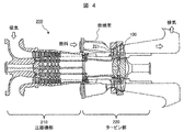
- 1 is a schematic cross-sectional view showing an example of a gas turbine equipped with a Co-based alloy product according to the present invention.
- 3 is an SEM observation image showing an example of a microstructure of a Co-based alloy AM body formed by a laser metal deposition method (LMD method).
- LMD method laser metal deposition method
- FIG. 3 is an SEM observation image showing an example of a microstructure of a Co-based alloy cast body formed by a precision casting method. 3 is a graph showing an example of the relationship between the average size of segregation cells in a Co-based alloy AM body and 0.2% proof stress in a Co-based alloy product.
- FIG. 4 is an SLM condition example for obtaining a Co-based alloy AM body according to the present invention, and is a graph showing the relationship between the thickness of the alloy powder bed and the local heat input.
- the components of Ti, Zr, Nb, and Ta, which are indispensable for forming the carbide phase, are notable at the final solidification part (eg, dendrite boundary or grain boundary) during melt solidification of the Co-based alloy.
- the carbide phase particles are precipitated along the dendrite boundaries and the crystal grain boundaries of the matrix phase.
- the average spacing of dendrite boundaries and the average grain size are usually in the order of 10 1 to 10 2 ⁇ m in ordinary cast Co-based alloy materials, so the average spacing of the carbide phase particles is also in the order of 10 1 to 10 2 ⁇ m.
- the average spacing of the carbide phase particles in the solidified portion is about 5 ⁇ m.
- precipitation strengthening in an alloy is inversely proportional to the average distance between precipitates, and precipitation strengthening is said to be effective when the average distance between precipitates is about 2 ⁇ m or less.
- the average distance between the precipitates does not reach the level, and the effect of sufficient precipitation strengthening cannot be obtained.
- Cr carbide phase is another carbide phase that can be precipitated in Co-based alloys. Since the Cr component has a high solid solubility in the Co-based alloy matrix and is difficult to segregate, the Cr carbide phase can be dispersed and precipitated in the matrix crystal grains. However, it is known that the Cr carbide phase has low lattice matching with the Co-based alloy matrix crystal and is not so effective as a precipitation strengthening phase.
- the present inventors in the Co-based alloy material, if it is possible to disperse and precipitate the carbide phase particles that contribute to precipitation strengthening in the matrix crystal grains, it is possible to dramatically improve the mechanical properties of the Co-based alloy material. I thought I could do it. In addition, it was thought that a heat-resistant alloy material superior to the precipitation-strengthened Ni-based alloy material could be provided in combination with the good corrosion resistance and wear resistance originally possessed by the Co-based alloy material.
- the present inventors diligently studied the alloy composition and manufacturing method for obtaining such a Co-based alloy material. As a result, by optimizing the alloy composition and controlling the heat input for local melting and rapid solidification within a predetermined range in the manufacturing using the AM method (particularly, selective laser melting method), It has been found that carbide phase particles that contribute to alloy strengthening can be dispersed and precipitated in the matrix crystal grains of the alloy material. The present invention has been completed based on this finding.
- FIG. 1 is a flow chart showing a process example of a method for producing a Co-based alloy product according to the present invention.
- the method for producing a Co-based alloy product according to the present invention roughly uses an alloy powder preparing step (S1) for preparing Co-based alloy powder and the prepared Co-based alloy powder.
- Selective laser melting step (S2) to form an AM body with a desired shape
- solution heat treatment step (S3) to subject the formed AM body to solution treatment
- S4 an aging heat treatment step of applying an aging treatment.
- the AM body obtained by the selective laser melting step S2 is the Co-based alloy laminate-molded body according to the present invention.
- This step S1 is a step of preparing a Co-based alloy powder having a predetermined chemical composition.
- the chemical composition is 0.08 mass% or more and 0.25 mass% or less C, 0.1 mass% or less B, 10 mass% or more and 30 mass% or less Cr, and Fe is 5 mass% or less and the total is 30 mass% or less.
- Fe and Ni, W and/or Mo in total 5 mass% to 12 mass%, Ti, Zr, Nb and Ta in total 0.5 mass% to 2 mass% and 0.5 mass% or less Si And 0.5% by mass or less of Mn and 0.003% by mass or more and 0.04% by mass or less of N, with the balance being Co and impurities.
- the C component constitutes an MC type carbide phase (which may be referred to as a Ti, Zr, Nb and/or Ta carbide phase or a strengthened carbide phase) which is a precipitation strengthening phase. It is an ingredient.
- the content of the C component is preferably 0.08 mass% or more and 0.25 mass% or less, more preferably 0.1 mass% or more and 0.2 mass% or less, and further preferably 0.12 mass% or more and 0.18 mass% or less. If the C content is less than 0.08 mass %, the amount of precipitation of the strengthened carbide phase will be insufficient, and the effect of improving the mechanical properties will not be sufficiently obtained. On the other hand, if the C content exceeds 0.25% by mass, excessive hardening causes the ductility and toughness of the alloy material to decrease.
- Component B is a component that contributes to the improvement of the bondability of crystal grain boundaries (so-called grain boundary strengthening). Although the B component is not an essential component, when it is contained, it is preferably 0.1% by mass or less, more preferably 0.005% by mass or more and 0.05% by mass or less. If the B content exceeds 0.1 mass %, cracks (for example, solidification cracks) tend to occur during formation of the AM body.
- the Cr component is a component that contributes to improvement in corrosion resistance and oxidation resistance.
- the content of the Cr component is preferably 10% by mass or more and 30% by mass or less, and more preferably 10% by mass or more and 25% by mass or less.
- the Cr content is more preferably 10% by mass or more and 18% by mass or less. If the Cr content is less than 10% by mass, corrosion resistance and oxidation resistance will be insufficient. On the other hand, if the Cr content exceeds 30 mass %, brittle ⁇ phase or Cr carbide phase is generated and mechanical properties (toughness, ductility, strength) are deteriorated.
- Ni 30% by mass or less Since the Ni component has similar characteristics to the Co component and is cheaper than Co, it is a component that can be contained by replacing a part of the Co component.
- the Ni component is not an essential component, but when contained, it is preferably 30% by mass or less, more preferably 20% by mass or less, further preferably 5% by mass or more and 15% by mass or less. If the Ni content exceeds 30 mass %, the wear resistance and resistance to local stress, which are the characteristics of Co-based alloys, deteriorate. This is considered to be due to the difference between the stacking fault energy of Co and that of Ni.
- the Fe component is much cheaper than Ni and has properties similar to those of the Ni component, and therefore, it is a component that can be contained by replacing a part of the Ni component. That is, the total content of Fe and Ni is preferably 30 mass% or less, more preferably 20 mass% or less, and further preferably 5 mass% or more and 15 mass% or less.
- the Fe component is not an essential component, but when it is contained, it is preferably 5% by mass or less, more preferably 3% by mass or less within a range smaller than the Ni content. When the Fe content exceeds 5 mass %, it becomes a cause of deterioration of corrosion resistance and mechanical properties.
- W and/or Mo 5 mass% or more and 12 mass% or less in total W component and Mo component are components that contribute to solid solution strengthening of the matrix phase.
- the total content of the W component and/or the Mo component is preferably 5% by mass or more and 12% by mass or less, and more preferably 7% by mass or more and 10% by mass or less.
- the total content of the W component and the Mo component is less than 5% by mass, the solid solution strengthening of the matrix becomes insufficient.
- the total content of the W component and the Mo component exceeds 12 mass %, a brittle ⁇ phase is likely to be formed and mechanical properties (toughness, ductility) are deteriorated.
- Re component 2% by mass or less Re component is a component that contributes to solid solution strengthening of the matrix phase and contributes to improvement of corrosion resistance.
- the Re component is not an essential component, but when it is contained, it is preferably 2% by mass or less and more preferably 0.5% by mass or more and 1.5% by mass or less in the form of partially replacing the W component or the Mo component. If the Re content exceeds 2% by mass, not only the action and effect of the Re component will be saturated, but also the material cost will increase.
- Ti, Zr, Nb and Ta 0.5% by mass or more and 2% by mass or less in total Ti component, Zr component, Nb component and Ta component are important components constituting the strengthened carbide phase (MC type carbide phase).
- the total content of Ti, Zr, Nb, and Ta components is preferably 0.5% by mass or more and 2% by mass or less, and more preferably 0.5% by mass or more and 1.8% by mass or less. If the total content is less than 0.5% by mass, the amount of precipitation of the strengthened carbide phase will be insufficient, and the effect of improving the mechanical properties will not be sufficiently obtained. On the other hand, when the total content exceeds 2% by mass, the reinforced carbide phase particles become coarse or accelerate the generation of brittle phase (for example, ⁇ phase) or generate oxide phase particles that do not contribute to precipitation strengthening. Mechanical properties deteriorate.
- the Ti content is preferably 0.01% by mass or more and 1% by mass or less, more preferably 0.05% by mass or more and 0.8% by mass or less.
- the Zr content is preferably 0.05% by mass or more and 1.5% by mass or less, and more preferably 0.1% by mass or more and 1.2% by mass or less.
- the Nb content is preferably 0.02% by mass or more and 1% by mass or less, more preferably 0.05% by mass or more and 0.8% by mass or less.
- the Ta content is preferably 0.05% by mass or more and 1.5% by mass or less, and more preferably 0.1% by mass or more and 1.2% by mass or less.
- the Si component plays a role of deoxidizing and contributes to the improvement of mechanical properties.
- the Si component is not an essential component, but when contained, it is preferably 0.5 mass% or less, more preferably 0.01 mass% or more and 0.3 mass% or less. If the Si content exceeds 0.5% by mass, coarse particles of oxide (for example, SiO 2 ) are formed, which causes a decrease in mechanical properties.
- the Mn component is a component that plays a role of deoxygenation/desulfurization and contributes to improvement of mechanical properties and corrosion resistance.
- the Mn component is not an essential component, but when contained, it is preferably 0.5 mass% or less, more preferably 0.01 mass% or more and 0.3 mass% or less. If the Mn content exceeds 0.5 mass %, coarse particles of sulfide (for example, MnS) are formed, which causes a decrease in mechanical properties and corrosion resistance.
- the N component is a component that contributes to stable formation of a strengthened carbide phase.
- the content of the N component is preferably 0.003 mass% or more and 0.04 mass% or less, more preferably 0.005 mass% or more and 0.03 mass% or less, and further preferably 0.007 mass% or more and 0.025 mass% or less. If the N content is less than 0.003% by mass, the effect of the N component cannot be sufficiently obtained. On the other hand, when the N content exceeds 0.04 mass %, coarse particles of nitride (eg, Cr nitride) are formed, which becomes a factor of lowering mechanical properties.
- nitride eg, Cr nitride
- Co component + impurities Co component is one of the main components of this alloy, and is the component with the maximum content.
- the Co-based alloy material has an advantage that it has corrosion resistance and wear resistance equal to or higher than that of the Ni-based alloy material.
- the Al component is one of the impurities of the present alloy and is not a component intentionally included. However, an Al content of 0.3 mass% or less is acceptable because it does not have a significant adverse effect on the mechanical properties of the Co-based alloy product. If the Al content exceeds 0.3% by mass, coarse particles of oxides or nitrides (for example, Al 2 O 3 or AlN) are formed, which causes deterioration of mechanical properties.
- the O component is also one of the impurities in this alloy and is not a component that is intentionally included. However, an O content of 0.04 mass% or less is acceptable because it does not have a large adverse effect on the mechanical properties of the Co-based alloy product. If the O content exceeds 0.04% by mass, coarse particles of various oxides (eg, Ti oxide, Zr oxide, Al oxide, Fe oxide, Si oxide) will be formed and cause deterioration of mechanical properties. become.
- various oxides eg, Ti oxide, Zr oxide, Al oxide, Fe oxide, Si oxide
- step S1 there is no particular limitation on the method/method for preparing the Co-based alloy powder, and the conventional method/method can be used.
- the atomizing process (S1b) may be performed.
- the atomizing method is not particularly limited, and the conventional method/method can be used.
- a gas atomizing method or a centrifugal atomizing method which can obtain spherical particles having a high purity, a homogeneous composition, can be preferably used.
- the particle size of the alloy powder is preferably 5 ⁇ m or more and 100 ⁇ m or less, more preferably 10 ⁇ m or more and 70 ⁇ m or less, and more preferably 10 ⁇ m or more and 50 ⁇ m or less, from the viewpoint of handleability and filling property of the alloy powder bed in the selective laser melting step S2 of the next step. More preferable. If the particle size of the alloy powder is less than 5 ⁇ m, the fluidity of the alloy powder is reduced in the next step S2 (the formability of the alloy powder bed is reduced), which is a factor that reduces the shape accuracy of the AM body.
- the alloy powder classifying step (S1c) for classifying the particle size of the alloy powder in the range of 5 ⁇ m or more and 100 ⁇ m or less.
- the element step S1c has been performed.
- This step S2 is a step of forming an AM body having a desired shape by the selective laser melting (SLM) method using the prepared Co-based alloy powder.
- SLM selective laser melting
- S2b laser melting and solidifying element step
- step S2 in order to obtain the desired fine structure (fine structure in which the strengthening carbide phase particles are dispersed and precipitated in the matrix phase crystal grains) in the final Co-based alloy product, it becomes the precursor of the product AM Controls the microstructure of the body. Then, in order to control the fine structure of the AM body, local melting and rapid solidification of the alloy powder bed are controlled.
- the alloy powder bed thickness h (unit: ⁇ m) of the alloy powder bed, the laser beam output P (unit: W), and the laser beam scanning speed S (unit: mm/s), “15 ⁇ h ⁇ 150” and “67(P/S)-3.5 ⁇ h ⁇ 2222(P/S)+13”, the alloy powder bed thickness h, laser light output P, laser light scanning speed S and Is preferably controlled. If the control conditions are not satisfied, an AM body having a desired fine structure cannot be obtained. By this step S2, the Co-based alloy AM body according to the present invention is obtained.
- the output P of the laser light and the scanning speed S of the laser light basically depend on the configuration of the laser device, but can be selected within the range of, for example, "10 ⁇ P ⁇ 1000" and "10 ⁇ S ⁇ 7000". Good.
- FIG. 2 is a scanning electron microscope (SEM) observation image showing an example of the microstructure of the Co-based alloy AM body according to the present invention. As shown in FIG. 2, the Co-based alloy AM body of the present invention has an extremely specific microstructure that has never been seen before.
- the AM body is a polycrystalline body having an average crystal grain size of 10 ⁇ m or more and 100 ⁇ m or less, and a segregation cell having an average size of 0.15 ⁇ m or more and 1.5 ⁇ m or less is formed in the crystal grains of the polycrystalline body. Further, particles of a strengthened carbide phase are precipitated at an average interval of 0.15 ⁇ m or more and 1.5 ⁇ m or less.
- the segregation cell size is defined as the average of the major axis and the minor axis.
- TEM-EDX transmission electron microscope-energy dispersive X-ray spectroscopy
- This step S3 is a step of subjecting the formed Co-based alloy AM body to solution treatment.
- solution treatment conditions heat treatment is preferably performed in a temperature range of 1100° C. or more and 1200° C. or less and a holding time of 0.5 hour or more and 10 hours or less.
- the cooling method after the heat treatment is not particularly limited, and any of water cooling, oil cooling, air cooling, and furnace cooling may be used.
- the average crystal grain size of the mother phase crystal grains is controlled to a range of 20 ⁇ m or more and 145 ⁇ m or less by recrystallization.
- the average crystal grain size is less than 20 ⁇ m or more than 145 ⁇ m, sufficient creep properties cannot be obtained in the final Co-based alloy product.
- the components segregated in the boundary region of the previous segregation cell start to aggregate to form a strengthened carbide phase, and as a result, the segregation cell is It disappeared (more precisely, the segregation cell could not be confirmed by SEM observation).
- the agglomeration point at which the strengthened carbide phase begins to form is considered to be the triple point/four-point position of the original segregation cell boundary, and it is in a state of being finely distributed throughout the matrix grains (inside the grains and on the grain boundaries). Become.
- the Co-based alloy product may be completed in this step S3.
- This step S4 is a step of subjecting the Co-based alloy AM body that has been subjected to the solution treatment to an aging treatment.
- the aging treatment condition heat treatment with a holding time of 0.5 hours to 10 hours in a temperature range of 750° C. to 1000° C. is preferable.
- the cooling method after the heat treatment is not particularly limited, and any of water cooling, oil cooling, air cooling, and furnace cooling may be used.
- the strengthened carbide phase that started to form in the solution heat treatment step S3 into the form of particles while suppressing excessive coarsening of the matrix phase crystal grains.
- the average crystal grain size of the mother phase crystal grains is 20 ⁇ m or more and 145 ⁇ m or less
- the reinforcing carbide phase particles are finely dispersed and precipitated in each crystal grain
- the average interparticle distance of the reinforcing carbide phase particles is 0.15 ⁇ m. It is possible to obtain a Co-based alloy product having a size of 1.5 ⁇ m or less.
- the strengthened carbide phase particles are dispersed and precipitated also on the grain boundaries of the parent phase crystal grains.
- a step of forming a corrosion-resistant coating layer or a surface finishing step on the Co-based alloy product obtained by the solution heat treatment step S3 or the aging heat treatment step S4. May be further performed.
- FIG. 3 is an example of a Co-based alloy product according to the present invention, and is a schematic perspective view showing a turbine vane as a turbine high temperature member.
- the turbine vane 100 is roughly composed of an inner ring side end wall 101, a blade portion 102, and an outer ring side end wall 103. Cooling structures are often formed inside the wings. As described above, since the turbine vane 100 has a very complicated shape and structure, the technical significance of the AM body formed by the near net shape and the alloy product based on the AM body is great.
- the length of the blade portion of the turbine vane (distance between both end walls) is about 170 mm.
- FIG. 4 is a schematic sectional view showing an example of a gas turbine equipped with the Co-based alloy product according to the present invention.
- the gas turbine 200 is roughly composed of a compressor section 210 that compresses intake air and a turbine section 220 that blows combustion gas of fuel to turbine blades to obtain rotational power.
- the turbine high temperature member of the present invention can be suitably used as the turbine nozzle 221 in the turbine section 220 or the turbine vane 100.
- the turbine hot component of the present invention is not limited to gas turbine applications, but may be other turbine applications (eg, steam turbine applications).
- alloy powder preparation step S1 Preparation of alloy powder IA-1 to IA-5 and CA-1 to CA-5) Co-based alloy powders having the chemical compositions shown in Table 1 were prepared (alloy powder preparation step S1). More specifically, first, after mixing the raw materials, a master alloy ingot producing step S1a of producing a master alloy ingot (mass: about 2 kg) by melting and casting by a vacuum high frequency induction melting method was performed. Next, the atomizing element step S1b of remelting the mother alloy ingot and forming alloy powder by a gas atomizing method in an argon gas atmosphere was performed.
- an alloy powder classifying step S1c for controlling the particle size was performed on each of the obtained alloy powders.
- an alloy powder whose particle size was classified into the range of 10 to 25 ⁇ m (particle size S) and an alloy powder classified into the range of 100 to 150 ⁇ m (particle size L) were prepared.
- the alloy powders IA-1 to IA-5 are alloy powders having a chemical composition satisfying the regulations of the present invention.
- the C content rate and the Cr content rate are out of the regulation of the present invention.
- the C content rate, the Ni content rate, and the total content rate of “Ti+Zr+Nb+Ta” are out of the regulation of the present invention.
- the alloy powder CA-3 the N content and the total content of “Ti+Zr+Nb+Ta” are out of the regulation of the present invention.
- the alloy powder CA-4 the total content of “Ti+Zr+Nb+Ta” is out of the range of the present invention.
- the W content and the total content of “Ti+Zr+Nb+Ta” are out of the regulation of the present invention.
- Example 2 (Production of SLM alloy products using IA-2 powder and SLM alloy products using CA-5 powder) An AM body (diameter 8 mm ⁇ height 10 mm) was formed by the SLM method using the alloy powder of IA-2 and CA-5 having the grain size S prepared in Experiment 1 (selective laser melting step S2).
- the control of the local heat input amount corresponds to the control of the cooling rate.
- Each of the AM bodies produced above was heat-treated by holding it at 1150°C for 4 hours (solution heat treatment step S3).
- the solution treated AM bodies were heat-treated at 900° C. for 4 hours (aging heat treatment step S4) to produce SLM alloy products using IA-2 powder and CA-5 powder.
- An SLM alloy product using was prepared.
- LMD alloy product using IA-2 powder and LMD alloy product using CA-5 powder An AM body was formed by the laser metal deposition method (LMD method) using the alloy powder of IA-2 and CA-5 having the grain size L prepared in Experiment 1, and the solution heat treatment step S3 and the aging heat treatment step S4 similar to the above By performing the above, an LMD alloy product using IA-2 powder and an LMD alloy product using CA-5 powder were produced.
- the LMD conditions were a laser light output P of 800 W and a laser light scanning speed S of 15 mm/s.
- the LMD method is a type of AM method, and is a method of additive manufacturing by performing alloy powder injection and laser irradiation at the same time.
- the local heat input of the LMD method is generally larger than the local heat input of the SLM method. In other words, the cooling rate in the LMD method becomes slower than that in the SLM method.
- a casting (diameter 8 mm x height 10 mm) was formed by precision casting using the alloy powder of IA-2 and CA-5 with grain size L prepared in Experiment 1, and the solution heat treatment step S3 similar to the above And an aging heat treatment step S4 were performed to produce a cast alloy product using the IA-2 powder and a cast alloy product using the CA-5 powder.
- Microstructure observation and mechanical property test Specimens for microstructure observation and mechanical property test were taken from the AM body, cast body, and manufactured product produced above, respectively, and microstructure observation and mechanical property test were performed.
- FIG. 5 is an SEM observation image showing an example of the microstructure of a Co-based alloy AM body formed by the LMD method
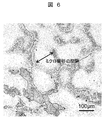
- FIG. 6 is an SEM showing an example of the microstructure of a Co-based alloy cast body formed by the precision casting method. It is an observed image.
- FIG. 2 shown above is an SEM observation image showing an example of the microstructure of the Co-based alloy AM body formed by the SLM method. The samples shown in FIGS. 2, 5 and 6 all use IA-2 as the alloy powder.
- the AM body formed by the SLM method has a segregation cell of about 1 ⁇ m size formed within the crystal grains of the polycrystalline body.
- the AM body formed by the LMD method is composed of a segregation cell in which each crystal grain of the polycrystalline body has a size of about 5 to 20 ⁇ m.
- the cast body formed by the precision casting method see FIG. 6
- microsegregation along the dendrite boundary was observed, and the interval of the microsegregation was about 100 to 300 ⁇ m.
- the average interparticle distance is It was found that the average size and the average interval of microsegregation were almost the same (illustration of the microstructure is omitted).
- solution treatment and aging treatment combine adjacent carbide phases to form large particles (as a result, It was found that the average interparticle distance of the carbide phase particles increases).
- FIG. 7 is a graph showing an example of the relationship between the average size of segregation cells in a Co-based alloy AM body and 0.2% proof stress in a Co-based alloy product. Note that FIG. 7 also shows data of a cast body and a cast alloy product for comparison. In the cast body, the average size of the segregation cells was substituted by the average interval of microsegregation.
- the Co-based alloy product produced using the CA-5 powder showed almost constant 0.2% proof stress without being affected by the average size of the segregation cell.
- the Co-based alloy product produced using IA-2 powder had a large change in 0.2% proof stress depending on the average size of the segregation cell.
- CA-5 powder has an excessively low total content of “Ti+Zr+Nb+Ta” (almost not included). Therefore, the product using the CA-5 powder had a fine structure in which the Cr carbide particles were precipitated without the precipitation of the strengthened carbide phase. This result confirms that Cr carbide particles are not very effective as precipitation strengthening particles. On the other hand, the product using the IA-2 powder had a fine structure in which reinforced carbide phase particles were precipitated. Therefore, it is considered that the 0.2% proof stress greatly changed depending on the average size of the segregation cell (the average interparticle distance of the carbide phase particles as a result).
- the 0.2% proof stress is required to be 500 MPa or more. Therefore, if a 0.2% proof stress of 500 MPa or more is judged as "pass” and less than 500 MPa is judged as "fail", the average size of the segregation cell (the resulting average interparticle distance of the carbide phase particles) is 0.15. It was confirmed that a mechanical property of “passing” was obtained in the range of up to 1.5 ⁇ m. In other words, it is considered that one of the factors that the conventional carbide phase precipitation Co-based alloy material could not obtain sufficient mechanical properties is that the average interparticle distance of the reinforced carbide phase particles could not be controlled within a desired range.
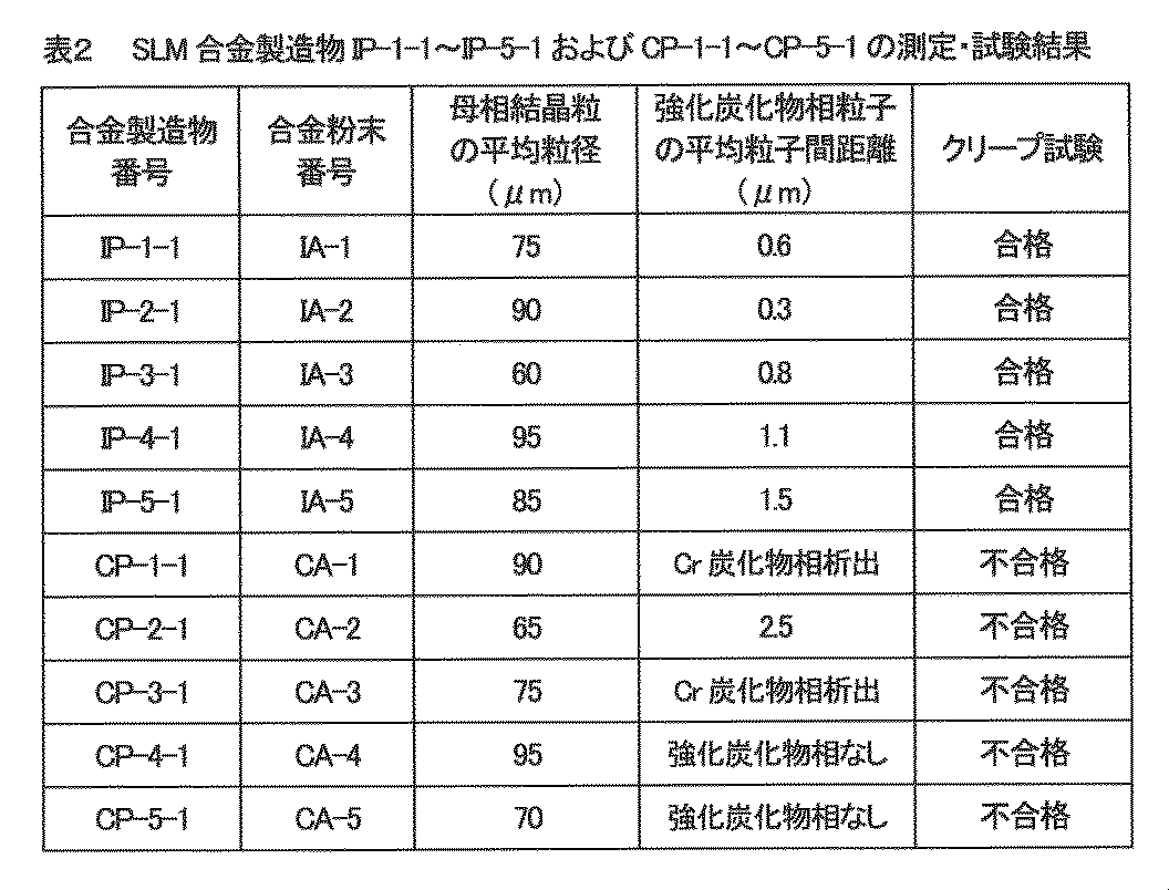
- Microstructure observation and mechanical property test From the SLM alloy products IP-1-1 to IP-5-1 and CP-1-1 to CP-5-1 produced above, sample specimens for microstructure observation and mechanical property test were collected. , Microstructure observation and mechanical property test were performed.
- a creep test was performed under the conditions of a temperature of 900°C and a stress of 98 MPa, and the creep rupture time was measured. From the required characteristics of the turbine high temperature member targeted by the present invention, a creep rupture time of 1100 hours or more was determined as "pass", and a creep rupture time of less than 1100 hours was determined as "fail”.
- a creep property that passes the test means that the temperature at which the creep rupture time is 100,000 hours at a stress of 58 MPa is 875°C or higher. It can be said that this creep characteristic is the same as that of the Ni-based alloy material.
- CP-1-1 and CP-3-1 From the results of CP-1-1 and CP-3-1, it is confirmed that Cr carbide particles are not so effective as precipitation strengthening particles.
- CP-4-1 and CP-5-1 are considered to be due to the fact that the strengthened carbide phase itself did not precipitate, because the total content of “Ti+Zr+Nb+Ta” was too small (because it was almost not included). Be done.
- the average grain size of the matrix crystal grains is preferably 20 to 145 ⁇ m.
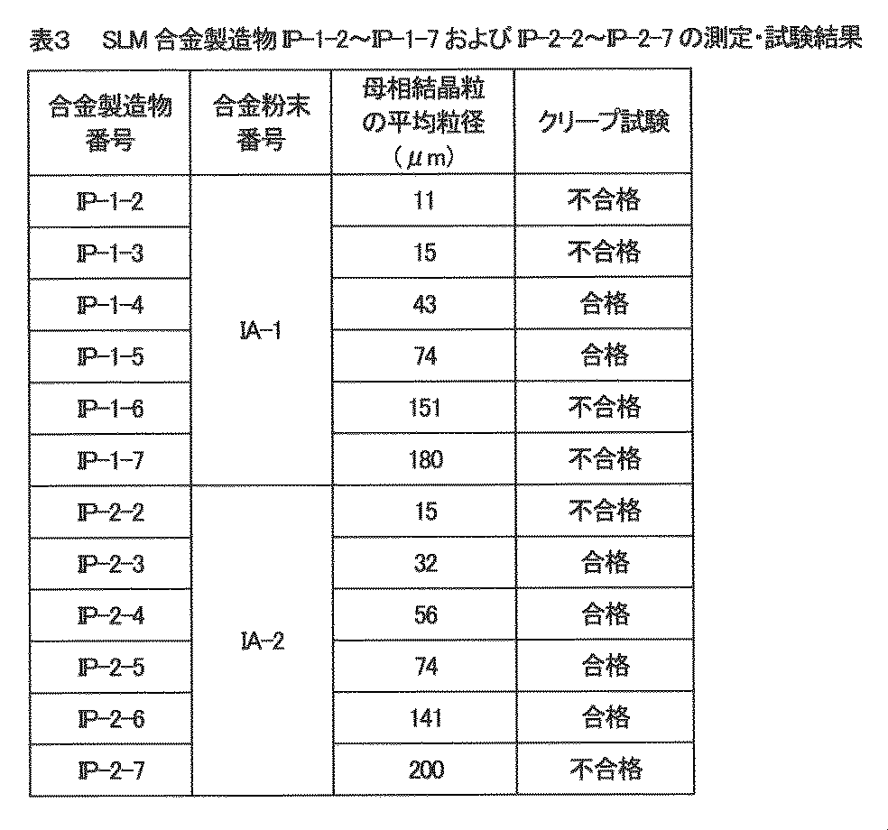
- the solution treatment is preferably a heat treatment in which the temperature is maintained in the temperature range of 1100 to 1200° C. for 0.5 to 10 hours.
- microstructure of each AM body prepared above was observed to measure the average size of the segregation cells.
- SEM and image processing software were used as in Experiment 2.
- FIG. 8 is an example of SLM conditions for obtaining the Co-based alloy AM body according to the present invention, and is a graph showing the relationship between the thickness of the alloy powder bed and the local heat input.
- FIG. 8 as a result of observing the microstructure of the AM body, those having an average size of the segregation cell in the range of 0.15 to 1.5 ⁇ m were judged as “pass” and indicated by “ ⁇ ” in the figure, and other It was judged as "fail” and indicated by “x” in the figure.
- the SLM conditions in the selective laser melting step S2 are as follows: the alloy powder bed thickness h (unit: ⁇ m), laser light output P (unit: W), and laser light scanning speed S (unit: It is confirmed that it is preferable to control so that the relationship with (mm/s) satisfies “15 ⁇ h ⁇ 150” and “67(P/S)-3.5 ⁇ h ⁇ 2222(P/S)+13”. .. That is, the hatched area is the area for acceptance determination.
- Turbine stationary blade 101... Inner ring side end wall, 102... Blade section, 103... Outer ring side end wall, 200... Gas turbine, 210... Compressor section, 220... ..Turbine part, 221... Turbine nozzle
Landscapes
- Chemical & Material Sciences (AREA)
- Engineering & Computer Science (AREA)
- Mechanical Engineering (AREA)
- Materials Engineering (AREA)
- Manufacturing & Machinery (AREA)
- Metallurgy (AREA)
- Organic Chemistry (AREA)
- Physics & Mathematics (AREA)
- Thermal Sciences (AREA)
- Crystallography & Structural Chemistry (AREA)
- Optics & Photonics (AREA)
- Powder Metallurgy (AREA)
Abstract
Description
前記Co基合金は、
0.08質量%以上0.25質量%以下の炭素(C)と、
0.1質量%以下のホウ素(B)と、
10質量%以上30質量%以下のクロム(Cr)と、
鉄(Fe)が5質量%以下で合計が30質量%以下の鉄およびニッケル(Ni)と、
合計が5質量%以上12質量%以下のタングステン(W)および/またはモリブデン(Mo)と、
合計が0.5質量%以上2質量%以下のチタン(Ti)、ジルコニウム(Zr)、ニオブ(Nb)およびタンタル(Ta)と、
0.5質量%以下のケイ素(Si)と、
0.5質量%以下のマンガン(Mn)と、
0.003質量%以上0.04質量%以下の窒素(N)とを含み、
残部がCoと不純物とからなる化学組成を有し、
前記積層造形体は、平均結晶粒径が10μm以上100μm以下の多結晶体であり、
前記多結晶体の結晶粒内には、前記Ti、前記Zr、前記Nbおよび/または前記Taを含むMC型炭化物相を形成する成分が境界領域に偏析していて平均サイズが0.15μm以上1.5μm以下の偏析セルが形成している、および/または前記MC型炭化物相の粒子が0.15μm以上1.5μm以下の平均粒子間距離で析出している、
ことを特徴とするCo基合金積層造形体を提供するものである。
(i)前記Co基合金の前記化学組成は、前記Tiが0.01質量%以上1質量%以下であり、前記Zrが0.05質量%以上1.5質量%以下であり、前記Nbが0.02質量%以上1質量%以下であり、前記Taが0.05質量%以上1.5質量%以下である。
(ii)前記Co基合金の前記化学組成は、前記不純物として、0.5質量%以下のアルミニウム(Al)と、0.04質量%以下の酸素(O)とを含む。
前記Co基合金は、
0.08質量%以上0.25質量%以下のCと、
0.1質量%以下のBと、
10質量%以上30質量%以下のCrと、
Feが5質量%以下で合計が30質量%以下のFeおよびNiと、
合計が5質量%以上12質量%以下のWおよび/またはMoと、
合計が0.5質量%以上2質量%以下のTi、Zr、NbおよびTaと、
0.5質量%以下のSiと、
0.5質量%以下のMnと、
0.003質量%以上0.04質量%以下のNとを含み、
残部がCoと不純物とからなる化学組成を有し、
前記製造物は、平均結晶粒径が20μm以上145μm以下の多結晶体であり、
前記多結晶体の結晶粒内には、前記Ti、前記Zr、前記Nbおよび/または前記Taを含むMC型炭化物相の粒子が0.15μm以上1.5μm以下の平均粒子間距離で析出している、
ことを特徴とするCo基合金製造物を提供するものである。
(iii)前記製造物は、室温0.2%耐力が500 MPa以上であり、58 MPaの応力で10万時間破断しないクリープ耐用温度が875℃以上である。
(iv)前記Co基合金の前記化学組成は、前記Tiが0.01質量%以上1質量%以下であり、前記Zrが0.05質量%以上1.5質量%以下であり、前記Nbが0.02質量%以上1質量%以下であり、前記Taが0.05質量%以上1.5質量%以下である。
(v)前記Co基合金の前記化学組成は、前記不純物として、0.5質量%以下のAlと、0.04質量%以下のOとを含む。
(vi)前記製造物は、タービン高温部材である。
(vii)前記タービン高温部材は、タービン静翼または燃焼器ノズルである。
前記化学組成を有するCo基合金粉末を用意する合金粉末用意工程と、
前記Co基合金粉末を敷き詰めて所定厚さの合金粉末床を用意する合金粉末床用意素工程と、前記合金粉末床の所定の領域にレーザ光を照射して該領域の前記Co基合金粉末を局所溶融・急冷凝固させるレーザ溶融凝固素工程と、を繰り返して積層造形体を形成する選択的レーザ溶融(SLM)工程とを有し、
前記SLM工程において、前記合金粉末床の前記所定厚さh(単位:μm)と前記レーザ光の出力P(単位:W)と前記レーザ光の走査速度S(単位:mm/s)との関係が「15 <h< 150」かつ「67(P/S)-3.5 <h< 2222(P/S)+13」を満たすように、前記所定厚さhと前記出力Pと前記走査速度Sとを制御する、
ことを特徴とするCo基合金積層造形体の製造方法を提供するものである。
(viii)前記合金粉末用意工程は、前記Co基合金粉末を5μm以上100μm以下の粒径範囲に分級する合金粉末分級素工程を含む。
前記化学組成を有するCo基合金粉末を用意する合金粉末用意工程と、
前記Co基合金粉末を敷き詰めて所定厚さの合金粉末床を用意する合金粉末床用意素工程と、前記合金粉末床の所定の領域にレーザ光を照射して該領域の前記Co基合金粉末を局所溶融急冷凝固させるレーザ溶融凝固素工程と、を繰り返して積層造形体を形成するSLM工程と、
前記積層造形体に対して、1100℃以上1200℃以下の温度範囲で0.5時間以上10時間以下の保持時間の溶体化処理を施す溶体化熱処理工程とを有し、
前記SLM工程において、前記合金粉末床の前記所定厚さh(単位:μm)と前記レーザ光の出力P(単位:W)と前記レーザ光の走査速度S(単位:mm/s)との関係が「15 <h< 150」かつ「67(P/S)-3.5 <h< 2222(P/S)+13」を満たすように、前記所定厚さhと前記出力Pと前記走査速度Sとを制御する、
ことを特徴とするCo基合金製造物の製造方法。
(ix)前記合金粉末用意工程は、前記Co基合金粉末を5μm以上100μm以下の粒径範囲に分級する合金粉末分級素工程を含む。
(x)前記溶体化熱処理工程の後に、前記積層造形体に対して、750℃以上1000℃以下の温度範囲で0.5時間以上10時間以下の保持時間の時効処理を施す時効熱処理工程を更に有する。
前述したように、Co基合金材では、炭化物相の析出による強化が種々研究開発されてきた。析出強化に寄与する炭化物相としては、例えば、Ti、Zr、Nb、TaのMC型炭化物相、およびそれら金属元素の複合炭化物相が挙げられる。
図1は、本発明に係るCo基合金製造物の製造方法の工程例を示すフロー図である。図1に示したように、本発明に係るCo基合金製造物の製造方法は、概略的に、Co基合金粉末を用意する合金粉末用意工程(S1)と、用意したCo基合金粉末を用いて所望形状のAM体を形成する選択的レーザ溶融工程(S2)と、形成したAM体に対して溶体化処理を施す溶体化熱処理工程(S3)と、溶体化処理を施したAM体に対して時効処理を施す時効熱処理工程(S4)と、を有する。なお、選択的レーザ溶融工程S2によって得られるAM体が、本発明に係るCo基合金積層造形体となる。
本工程S1は、所定の化学組成を有するCo基合金粉末を用意する工程である。該化学組成は、0.08質量%以上0.25質量%以下のCと、0.1質量%以下のBと、10質量%以上30質量%以下のCrと、Feが5質量%以下で合計が30質量%以下のFeおよびNiと、合計が5質量%以上12質量%以下のWおよび/またはMoと、合計が0.5質量%以上2質量%以下のTi、Zr、NbおよびTaと、0.5質量%以下のSiと、0.5質量%以下のMnと、0.003質量%以上0.04質量%以下のNとを含み、残部がCoと不純物とからなることが好ましい。
C成分は、析出強化相となるMC型炭化物相(Ti、Zr、Nbおよび/またはTaの炭化物相、強化炭化物相と称する場合がある)を構成する重要な成分である。C成分の含有率は、0.08質量%以上0.25質量%以下が好ましく、0.1質量%以上0.2質量%以下がより好ましく、0.12質量%以上0.18質量%以下が更に好ましい。C含有率が0.08質量%未満になると、強化炭化物相の析出量が不足し、機械的特性向上の作用効果が十分に得られない。一方、C含有率が0.25質量%超になると、過度に硬化することで、合金材の延性や靱性が低下する。
B成分は、結晶粒界の接合性の向上(いわゆる粒界強化)に寄与する成分である。B成分は必須成分ではないが、含有させる場合、0.1質量%以下が好ましく、0.005質量%以上0.05質量%以下がより好ましい。B含有率が0.1質量%超になると、AM体形成時に割れ(例えば、凝固割れ)が発生し易くなる。
Cr成分は、耐食性や耐酸化性の向上に寄与する成分である。Cr成分の含有率は、10質量%以上30質量%以下が好ましく、10質量%以上25質量%以下がより好ましい。Co基合金製造物の最表面に耐食性被覆層を別途設けるような場合は、Cr成分の含有率は、10質量%以上18質量%以下が更に好ましい。Cr含有率が10質量%未満になると、耐食性や耐酸化性が不十分になる。一方、Cr含有率が30質量%超になると、脆性のσ相が生成したりCr炭化物相が生成したりして機械的特性(靱性、延性、強さ)が低下する。
Ni成分は、Co成分と類似した特性を有しかつCoに比して安価なことから、Co成分の一部を置き換えるかたちで含有させることができる成分である。Ni成分は必須成分ではないが、含有させる場合、30質量%以下が好ましく、20質量%以下がより好ましく、5質量%以上15質量%以下が更に好ましい。Ni含有率が30質量%超になると、Co基合金の特徴である耐摩耗性や局所応力への耐性が低下する。これは、Coの積層欠陥エネルギーとNiのそれとの差異に起因すると考えられる。
Fe成分は、Niよりもはるかに安価でありかつNi成分と類似した性状を有することから、Ni成分の一部を置き換えるかたちで含有させることができる成分である。すなわち、FeおよびNiの合計含有率は30質量%以下が好ましく、20質量%以下がより好ましく、5質量%以上15質量%以下が更に好ましい。Fe成分は必須成分ではないが、含有させる場合、Ni含有率よりも少ない範囲で5質量%以下が好ましく、3質量%以下がより好ましい。Fe含有率が5質量%超になると、耐食性や機械的特性の低下要因になる。
W成分およびMo成分は、母相の固溶強化に寄与する成分である。W成分および/またはMo成分の含有率は、合計で5質量%以上12質量%以下が好ましく、7質量%以上10質量%以下がより好ましい。W成分とMo成分との合計含有率が5質量%未満になると、母相の固溶強化が不十分になる。一方、W成分とMo成分との合計含有率が12質量%超になると、脆性のσ相が生成し易くなって機械的特性(靱性、延性)が低下する。
Re成分は、母相の固溶強化に寄与すると共に、耐食性の向上に寄与する成分である。Re成分は必須成分ではないが、含有させる場合、W成分またはMo成分の一部を置き換えるかたちで2質量%以下が好ましく、0.5質量%以上1.5質量%以下がより好ましい。Re含有率が2質量%超になると、Re成分の作用効果が飽和するのに加えて、材料コストの増加がデメリットになる。
Ti成分、Zr成分、Nb成分およびTa成分は、強化炭化物相(MC型炭化物相)を構成する重要な成分である。Ti、Zr、NbおよびTa成分の含有率は、合計0.5質量%以上2質量%以下が好ましく、合計0.5質量%以上1.8質量%以下がより好ましい。合計含有率が0.5質量%未満になると、強化炭化物相の析出量が不足し、機械的特性向上の作用効果が十分に得られない。一方、当該合計含有率が2質量%超になると、強化炭化物相粒子が粗大化したり脆性相(例えばσ相)の生成を促進したり析出強化に寄与しない酸化物相粒子を生成したりして機械的特性が低下する。
Si成分は、脱酸素の役割を担って機械的特性の向上に寄与する成分である。Si成分は必須成分ではないが、含有させる場合、0.5質量%以下が好ましく、0.01質量%以上0.3質量%以下がより好ましい。Si含有率が0.5質量%超になると、酸化物(例えばSiO2)の粗大粒子を形成して機械的特性の低下要因になる。
Mn成分は、脱酸素・脱硫の役割を担って機械的特性の向上や耐腐食性の向上に寄与する成分である。Mn成分は必須成分ではないが、含有させる場合、0.5質量%以下が好ましく、0.01質量%以上0.3質量%以下がより好ましい。Mn含有率が0.5質量%超になると、硫化物(例えばMnS)の粗大粒子を形成して機械的特性や耐食性の低下要因になる。
N成分は、強化炭化物相の安定生成に寄与する成分である。N成分の含有率は、0.003質量%以上0.04質量%以下が好ましく、0.005質量%以上0.03質量%以下がより好ましく、0.007質量%以上0.025質量%以下が更に好ましい。N含有率が0.003質量%未満になると、N成分の作用効果が十分に得られない。一方、N含有率が0.04質量%超になると、窒化物(例えばCr窒化物)の粗大粒子を形成して機械的特性の低下要因になる。
Co成分は、本合金の主要成分の一つであり、最大含有率の成分である。前述したように、Co基合金材は、Ni基合金材と同等以上の耐食性や耐摩耗性を有する利点がある。
本工程S2は、用意したCo基合金粉末を用いて選択的レーザ溶融(SLM)法により所望形状のAM体を形成する工程である。具体的には、Co基合金粉末を敷き詰めて所定厚さの合金粉末床を用意する合金粉末床用意素工程(S2a)と、合金粉末床の所定の領域にレーザ光を照射して該領域のCo基合金粉末を局所溶融・急冷凝固させるレーザ溶融凝固素工程(S2b)と、を繰り返してAM体を形成する工程である。
図2は、本発明に係るCo基合金AM体の微細組織の一例を示す走査型電子顕微鏡(SEM)観察像である。図2に示したように、本発明のCo基合金AM体は、今までに見たことのないような極めて特異的な微細組織を有している。
本工程S3は、形成したCo基合金AM体に対して溶体化処理を施す工程である。溶体化処理条件としては、1100℃以上1200℃以下の温度範囲で0.5時間以上10時間以下の保持時間の熱処理が好ましい。熱処理後の冷却方法に特段の限定はなく、水冷、油冷、空冷、炉冷のいずれでも構わない。
本工程S4は、溶体化処理を施したCo基合金AM体に対して時効処理を施す工程である。時効処理条件としては、750℃以上1000℃以下の温度範囲で0.5時間以上10時間以下の保持時間の熱処理が好ましい。熱処理後の冷却方法に特段の限定はなく、水冷、油冷、空冷、炉冷のいずれでも構わない。
図1には図示していないが、溶体化熱処理工程S3や時効熱処理工程S4によって得られたCo基合金製造物に対して、必要に応じて、耐食性被覆層を形成する工程や表面仕上げの工程を更に行ってもよい。
図3は、本発明に係るCo基合金製造物の一例であり、タービン高温部材としてのタービン静翼を示す斜視模式図である。図3に示したように、タービン静翼100は、概略的に、内輪側エンドウォール101と翼部102と外輪側エンドウォール103とから構成される。翼部の内部には、しばしば冷却構造が形成される。このように、タービン静翼100は非常に複雑な形状・構造を有することから、ニアネットシェイプで形成されるAM体および該AM体を基にした合金製造物の技術的意義は大きい。
(合金粉末IA-1~IA-5およびCA-1~CA-5の用意)
表1に示す化学組成を有するCo基合金粉末を用意した(合金粉末用意工程S1)。より具体的には、まず、原料を混合した後、真空高周波誘導溶解法により溶解・鋳造して母合金塊(質量:約2 kg)を作製する母合金塊作製素工程S1aを行った。次に、該母合金塊を再溶解して、アルゴンガス雰囲気中のガスアトマイズ法により合金粉末を形成するアトマイズ素工程S1bを行った。

(IA-2粉末を用いたSLM合金製造物、およびCA-5粉末を用いたSLM合金製造物の作製)
実験1で用意したIA-2およびCA-5の粒度Sの合金粉末を用いてSLM法によりAM体(直径8 mm×高さ10 mm)を形成した(選択的レーザ溶融工程S2)。SLM条件は、合金粉末床の厚さhを100μmとし、レーザ光の出力Pを100 Wとし、レーザ光の走査速度S(mm/s)を種々変更することによって局所入熱量P/S(単位:W・s/mm=J/mm)を制御した。局所入熱量の制御は、冷却速度の制御に相当する。
実験1で用意したIA-2およびCA-5の粒度Lの合金粉末を用いてレーザ金属堆積法(LMD法)によりAM体を形成し、上記と同様の溶体化熱処理工程S3と時効熱処理工程S4とを行って、IA-2粉末を用いたLMD合金製造物およびCA-5粉末を用いたLMD合金製造物を作製した。LMD条件は、レーザ光の出力Pを800 Wとし、レーザ光の走査速度Sを15 mm/sとした。
実験1で用意したIA-2およびCA-5の粒度Lの合金粉末を用いて精密鋳造法により鋳造体(直径8 mm×高さ10 mm)を形成し、上記と同様の溶体化熱処理工程S3と時効熱処理工程S4とを行って、IA-2粉末を用いた鋳造合金製造物およびCA-5粉末を用いた鋳造合金製造物を作製した。
上記で作製したAM体、鋳造体、および製造物から、微細組織観察用および機械的特性試験用の試験片をそれぞれ採取し、微細組織観察および機械的特性試験を行った。
(IA-1~IA-5粉末を用いたSLM合金製造物IP-1-1~IP-5-1、およびCA-1~CA-5粉末を用いたSLM合金製造物CP-1-1~CP-5-1の作製)
実験1で用意したIA-1~IA-5およびCA-1~CA-5の粒度Sの合金粉末を用いてSLM法によりAM体(直径8 mm×高さ10 mm)を形成した(選択的レーザ溶融工程S2)。SLM条件としては、実験2の結果を受けて、炭化物相粒子の平均粒子間距離が0.15~1.5μmの範囲となるように制御した。
上記で作製したSLM合金製造物IP-1-1~IP-5-1およびCP-1-1~CP-5-1から、微細組織観察用および機械的特性試験用の試験片をそれぞれ採取し、微細組織観察および機械的特性試験を行った。
(SLM合金製造物IP-1-2~IP-1-7およびIP-2-2~IP-2-7の作製)
実験1で用意したIA-1およびIA-2の粒度Sの合金粉末を用いてSLM法によりAM体(直径8 mm×高さ10 mm)を作製した(選択的レーザ溶融工程S2)。SLM条件としては、実験2の結果を受けて、炭化物相粒子の平均粒子間距離が0.15~1.5μmの範囲となるように制御した。
上記で作製したSLM合金製造物IP-1-2~IP-1-7およびIP-2-2~IP-2-7から、微細組織観察用および機械的特性試験用の試験片をそれぞれ採取し、微細組織観察および機械的特性試験を行った。
(選択的レーザ溶融工程におけるSLM条件の検討)
実験1で用意したIA-4の粒度Sの合金粉末を用いてSLM法によりAM体(直径8 mm×高さ10 mm)を形成した(選択的レーザ溶融工程S2)。SLM条件は、レーザ光の出力Pを85 Wとし、合金粉末床の厚さhおよびレーザ光の走査速度S(mm/s)を種々変更することによって局所入熱量P/S(単位:W・s/mm=J/mm)を制御した。
Claims (14)
- コバルト基合金からなる積層造形体であって、
前記コバルト基合金は、
0.08質量%以上0.25質量%以下の炭素と、
0.1質量%以下のホウ素と、
10質量%以上30質量%以下のクロムと、
鉄が5質量%以下で合計が30質量%以下の鉄およびニッケルと、
合計が5質量%以上12質量%以下のタングステンおよび/またはモリブデンと、
合計が0.5質量%以上2質量%以下のチタン、ジルコニウム、ニオブおよびタンタルと、
0.5質量%以下のケイ素と、
0.5質量%以下のマンガンと、
0.003質量%以上0.04質量%以下の窒素とを含み、
残部がコバルトと不純物とからなる化学組成を有し、前記積層造形体は、平均結晶粒径が10μm以上100μm以下の多結晶体であり、
前記多結晶体の結晶粒内には、前記チタン、前記ジルコニウム、前記ニオブおよび/または前記タンタルを含むMC型炭化物相を形成する成分が境界領域に偏析していて平均サイズが0.15μm以上1.5μm以下の偏析セルが形成している、および/または前記MC型炭化物相の粒子が0.15μm以上1.5μm以下の平均粒子間距離で析出している、
ことを特徴とするコバルト基合金積層造形体。 - 請求項1に記載のコバルト基合金積層造形体において、
前記コバルト基合金の前記化学組成は、
前記チタンが0.01質量%以上1質量%以下であり、
前記ジルコニウムが0.05質量%以上1.5質量%以下であり、
前記ニオブが0.02質量%以上1質量%以下であり、
前記タンタルが0.05質量%以上1.5質量%以下である、
ことを特徴とするコバルト基合金積層造形体。 - 請求項1又は請求項2に記載のコバルト基合金積層造形体において、
前記コバルト基合金の前記化学組成は、前記不純物として、
0.5質量%以下のアルミニウムと、
0.04質量%以下の酸素とを含む、
ことを特徴とするコバルト基合金積層造形体。 - コバルト基合金からなる製造物であって、
前記コバルト基合金は、
0.08質量%以上0.25質量%以下の炭素と、
0.1質量%以下のホウ素と、
10質量%以上30質量%以下のクロムと、
鉄が5質量%以下で合計が30質量%以下の鉄およびニッケルと、
合計が5質量%以上12質量%以下のタングステンおよび/またはモリブデンと、
合計が0.5質量%以上2質量%以下のチタン、ジルコニウム、ニオブおよびタンタルと、
0.5質量%以下のケイ素と、
0.5質量%以下のマンガンと、
0.003質量%以上0.03質量%以下の窒素とを含み、
残部がコバルトと不純物とからなる化学組成を有し、
前記製造物は、平均結晶粒径が20μm以上145μm以下の多結晶体であり、
前記多結晶体の結晶粒内には、前記チタン、前記ジルコニウム、前記ニオブおよび/または前記タンタルを含むMC型炭化物相の粒子が0.15μm以上1.5μm以下の平均粒子間距離で析出している、
ことを特徴とするコバルト基合金製造物。 - 請求項4に記載のコバルト基合金製造物において、
前記製造物は、室温0.2%耐力が500 MPa以上であり、58 MPaの応力で10万時間破断しないクリープ耐用温度が875℃以上であることを特徴とするコバルト基合金製造物。 - 請求項4又は請求項5に記載のコバルト基合金製造物において、
前記コバルト基合金の前記化学組成は、
前記チタンが0.01質量%以上1質量%以下であり、
前記ジルコニウムが0.05質量%以上1.5質量%以下であり、
前記ニオブが0.02質量%以上1質量%以下であり、
前記タンタルが0.05質量%以上1.5質量%以下である、
ことを特徴とするコバルト基合金製造物。 - 請求項4乃至請求項6のいずれか一項に記載のコバルト基合金製造物において、
前記コバルト基合金の前記化学組成は、前記不純物として、
0.5質量%以下のアルミニウムと、
0.04質量%以下の酸素とを含む、
ことを特徴とするコバルト基合金製造物。 - 請求項4乃至請求項7のいずれか一項に記載のコバルト基合金製造物において、
前記製造物は、タービン高温部材であることを特徴とするコバルト基合金製造物。 - 請求項8に記載のコバルト基合金製造物において、
前記タービン高温部材は、タービン静翼または燃焼器ノズルであることを特徴とするコバルト基合金製造物。 - 請求項1乃至請求項3のいずれか一項に記載のコバルト基合金積層造形体の製造方法であって、
前記化学組成を有するコバルト基合金粉末を用意する合金粉末用意工程と、
前記コバルト基合金粉末を敷き詰めて所定厚さの合金粉末床を用意する合金粉末床用意素工程と、前記合金粉末床の所定の領域にレーザ光を照射して該領域の前記コバルト基合金粉末を局所溶融・急冷凝固させるレーザ溶融凝固素工程と、を繰り返して積層造形体を形成する選択的レーザ溶融工程とを有し、
前記選択的レーザ溶融工程において、前記合金粉末床の前記所定厚さh(単位:μm)と前記レーザ光の出力P(単位:W)と前記レーザ光の走査速度S(単位:mm/s)との関係が「15 <h< 150」かつ「67(P/S)-3.5 <h< 2222(P/S)+13」を満たすように、前記所定厚さhと前記出力Pと前記走査速度Sとを制御する、
ことを特徴とするコバルト基合金積層造形体の製造方法。 - 請求項10に記載のコバルト基合金積層造形体の製造方法において、
前記合金粉末用意工程は、前記コバルト基合金粉末を5μm以上100μm以下の粒径範囲に分級する合金粉末分級素工程を含むことを特徴とするコバルト基合金積層造形体の製造方法。 - 請求項4乃至請求項9のいずれか一項に記載のコバルト基合金製造物の製造方法であって、
前記化学組成を有するコバルト基合金粉末を用意する合金粉末用意工程と、
前記コバルト基合金粉末を敷き詰めて所定厚さの合金粉末床を用意する合金粉末床用意素工程と、前記合金粉末床の所定の領域にレーザ光を照射して該領域の前記コバルト基合金粉末を局所溶融急冷凝固させるレーザ溶融凝固素工程と、を繰り返して積層造形体を形成する選択的レーザ溶融工程と、
前記積層造形体に対して、1100℃以上1200℃以下の温度範囲で0.5時間以上10時間以下の保持時間の溶体化処理を施す溶体化熱処理工程とを有し、
前記選択的レーザ溶融工程において、前記合金粉末床の前記所定厚さh(単位:μm)と前記レーザ光の出力P(単位:W)と前記レーザ光の走査速度S(単位:mm/s)との関係が「15 <h< 150」かつ「67(P/S)-3.5 <h< 2222(P/S)+13」を満たすように、前記所定厚さhと前記出力Pと前記走査速度Sとを制御する、
ことを特徴とするコバルト基合金製造物の製造方法。 - 請求項12に記載のコバルト基合金製造物の製造方法において、
前記合金粉末用意工程は、前記コバルト基合金粉末を5μm以上100μm以下の粒径範囲に分級する合金粉末分級素工程を含むことを特徴とするコバルト基合金製造物の製造方法。 - 請求項12又は請求項13に記載のコバルト基合金製造物の製造方法において、
前記溶体化熱処理工程の後に、前記積層造形体に対して、750℃以上1000℃以下の温度範囲で0.5時間以上10時間以下の保持時間の時効処理を施す時効熱処理工程を更に有することを特徴とするコバルト基合金製造物の製造方法。
Priority Applications (3)
| Application Number | Priority Date | Filing Date | Title |
|---|---|---|---|
| PCT/JP2018/045245 WO2020121367A1 (ja) | 2018-12-10 | 2018-12-10 | コバルト基合金積層造形体、コバルト基合金製造物、およびそれらの製造方法 |
| CA3061851A CA3061851C (en) | 2018-12-10 | 2018-12-10 | Cobalt based alloy additive manufactured article, cobalt based alloy product, and method for manufacturing same |
| AU2018422117A AU2018422117B2 (en) | 2018-12-10 | 2018-12-10 | Cobalt based alloy additive manufactured article, cobalt based alloy product, and method for manufacturing same |
Applications Claiming Priority (1)
| Application Number | Priority Date | Filing Date | Title |
|---|---|---|---|
| PCT/JP2018/045245 WO2020121367A1 (ja) | 2018-12-10 | 2018-12-10 | コバルト基合金積層造形体、コバルト基合金製造物、およびそれらの製造方法 |
Publications (1)
| Publication Number | Publication Date |
|---|---|
| WO2020121367A1 true WO2020121367A1 (ja) | 2020-06-18 |
Family
ID=71070786
Family Applications (1)
| Application Number | Title | Priority Date | Filing Date |
|---|---|---|---|
| PCT/JP2018/045245 Ceased WO2020121367A1 (ja) | 2018-12-10 | 2018-12-10 | コバルト基合金積層造形体、コバルト基合金製造物、およびそれらの製造方法 |
Country Status (3)
| Country | Link |
|---|---|
| AU (1) | AU2018422117B2 (ja) |
| CA (1) | CA3061851C (ja) |
| WO (1) | WO2020121367A1 (ja) |
Cited By (10)
| Publication number | Priority date | Publication date | Assignee | Title |
|---|---|---|---|---|
| EP3733885A4 (en) * | 2019-03-07 | 2020-12-30 | Mitsubishi Power, Ltd. | HEAT EXCHANGER |
| CN114015922A (zh) * | 2020-07-17 | 2022-02-08 | 西安铂力特增材技术股份有限公司 | 用于增材制造的钴基高温合金金属粉末材料及其制备方法 |
| CN114054773A (zh) * | 2021-11-09 | 2022-02-18 | 南京理工大学 | 析出相非均匀分布的叠层异构铝合金板材的制备方法 |
| US11306372B2 (en) | 2019-03-07 | 2022-04-19 | Mitsubishi Power, Ltd. | Cobalt-based alloy powder, cobalt-based alloy sintered body, and method for producing cobalt-based alloy sintered body |
| US11325189B2 (en) | 2017-09-08 | 2022-05-10 | Mitsubishi Heavy Industries, Ltd. | Cobalt based alloy additive manufactured article, cobalt based alloy product, and method for manufacturing same |
| US11414728B2 (en) | 2019-03-07 | 2022-08-16 | Mitsubishi Heavy Industries, Ltd. | Cobalt based alloy product, method for manufacturing same, and cobalt based alloy article |
| US11499208B2 (en) | 2019-03-07 | 2022-11-15 | Mitsubishi Heavy Industries, Ltd. | Cobalt based alloy product |
| JP7237222B1 (ja) | 2021-09-30 | 2023-03-10 | 三菱重工業株式会社 | コバルト基合金造形物およびコバルト基合金製造物の製造方法 |
| US11613795B2 (en) | 2019-03-07 | 2023-03-28 | Mitsubishi Heavy Industries, Ltd. | Cobalt based alloy product and method for manufacturing same |
| CN115896546A (zh) * | 2021-09-30 | 2023-04-04 | 大同特殊钢株式会社 | 钴基合金制品以及钴基合金制品的制造方法 |
Families Citing this family (3)
| Publication number | Priority date | Publication date | Assignee | Title |
|---|---|---|---|---|
| US20220220584A1 (en) * | 2020-09-04 | 2022-07-14 | Mitsubishi Heavy Industries, Ltd. | Cobalt based alloy product and method for manufacturing same |
| CN116990107B (zh) * | 2023-06-08 | 2024-05-24 | 辽宁红银金属有限公司 | 一种钴基高温合金标准样品及其制备方法 |
| CN116673499B (zh) * | 2023-06-20 | 2026-02-10 | 武汉大学 | 基于水导激光的陶瓷增强金属基复合材料及其制备方法 |
Citations (4)
| Publication number | Priority date | Publication date | Assignee | Title |
|---|---|---|---|---|
| JPS61243143A (ja) * | 1984-11-06 | 1986-10-29 | Agency Of Ind Science & Technol | Co基超塑性合金およびその製造方法 |
| JPH09157780A (ja) * | 1995-12-05 | 1997-06-17 | Hitachi Ltd | 高耐食性Co基合金 |
| JP2015072007A (ja) * | 2013-09-09 | 2015-04-16 | ゼネラル・エレクトリック・カンパニイ | 3次元印刷プロセス、スワール装置、及び熱管理プロセス |
| JP2017186620A (ja) * | 2016-04-06 | 2017-10-12 | セイコーエプソン株式会社 | 粉末冶金用金属粉末、コンパウンド、造粒粉末、焼結体および耐熱部品 |
-
2018
- 2018-12-10 WO PCT/JP2018/045245 patent/WO2020121367A1/ja not_active Ceased
- 2018-12-10 CA CA3061851A patent/CA3061851C/en active Active
- 2018-12-10 AU AU2018422117A patent/AU2018422117B2/en not_active Ceased
Patent Citations (4)
| Publication number | Priority date | Publication date | Assignee | Title |
|---|---|---|---|---|
| JPS61243143A (ja) * | 1984-11-06 | 1986-10-29 | Agency Of Ind Science & Technol | Co基超塑性合金およびその製造方法 |
| JPH09157780A (ja) * | 1995-12-05 | 1997-06-17 | Hitachi Ltd | 高耐食性Co基合金 |
| JP2015072007A (ja) * | 2013-09-09 | 2015-04-16 | ゼネラル・エレクトリック・カンパニイ | 3次元印刷プロセス、スワール装置、及び熱管理プロセス |
| JP2017186620A (ja) * | 2016-04-06 | 2017-10-12 | セイコーエプソン株式会社 | 粉末冶金用金属粉末、コンパウンド、造粒粉末、焼結体および耐熱部品 |
Cited By (14)
| Publication number | Priority date | Publication date | Assignee | Title |
|---|---|---|---|---|
| US11325189B2 (en) | 2017-09-08 | 2022-05-10 | Mitsubishi Heavy Industries, Ltd. | Cobalt based alloy additive manufactured article, cobalt based alloy product, and method for manufacturing same |
| US11427893B2 (en) | 2019-03-07 | 2022-08-30 | Mitsubishi Heavy Industries, Ltd. | Heat exchanger |
| US11306372B2 (en) | 2019-03-07 | 2022-04-19 | Mitsubishi Power, Ltd. | Cobalt-based alloy powder, cobalt-based alloy sintered body, and method for producing cobalt-based alloy sintered body |
| US11414728B2 (en) | 2019-03-07 | 2022-08-16 | Mitsubishi Heavy Industries, Ltd. | Cobalt based alloy product, method for manufacturing same, and cobalt based alloy article |
| EP3733885A4 (en) * | 2019-03-07 | 2020-12-30 | Mitsubishi Power, Ltd. | HEAT EXCHANGER |
| US11499208B2 (en) | 2019-03-07 | 2022-11-15 | Mitsubishi Heavy Industries, Ltd. | Cobalt based alloy product |
| US11613795B2 (en) | 2019-03-07 | 2023-03-28 | Mitsubishi Heavy Industries, Ltd. | Cobalt based alloy product and method for manufacturing same |
| CN114015922A (zh) * | 2020-07-17 | 2022-02-08 | 西安铂力特增材技术股份有限公司 | 用于增材制造的钴基高温合金金属粉末材料及其制备方法 |
| JP7237222B1 (ja) | 2021-09-30 | 2023-03-10 | 三菱重工業株式会社 | コバルト基合金造形物およびコバルト基合金製造物の製造方法 |
| CN115896546A (zh) * | 2021-09-30 | 2023-04-04 | 大同特殊钢株式会社 | 钴基合金制品以及钴基合金制品的制造方法 |
| JP2023051722A (ja) * | 2021-09-30 | 2023-04-11 | 三菱重工業株式会社 | コバルト基合金造形物およびコバルト基合金製造物の製造方法 |
| US12195828B2 (en) | 2021-09-30 | 2025-01-14 | Daido Steel Co., Ltd. | Cobalt-based alloy product and method for producing cobalt-based alloy product |
| CN114054773A (zh) * | 2021-11-09 | 2022-02-18 | 南京理工大学 | 析出相非均匀分布的叠层异构铝合金板材的制备方法 |
| CN114054773B (zh) * | 2021-11-09 | 2024-03-22 | 南京理工大学 | 析出相非均匀分布的叠层异构铝合金板材的制备方法 |
Also Published As
| Publication number | Publication date |
|---|---|
| AU2018422117B2 (en) | 2021-06-03 |
| CA3061851C (en) | 2022-05-31 |
| CA3061851A1 (en) | 2020-06-10 |
| AU2018422117A1 (en) | 2020-06-25 |
Similar Documents
| Publication | Publication Date | Title |
|---|---|---|
| KR102225271B1 (ko) | 코발트기 합금 재료 | |
| JP6713071B2 (ja) | コバルト基合金積層造形体の製造方法 | |
| CA3061851C (en) | Cobalt based alloy additive manufactured article, cobalt based alloy product, and method for manufacturing same | |
| CN112004951B (zh) | 钴基合金制造物及其制造方法 | |
| CN112004952B (zh) | 钴基合金制造物的制造方法 | |
| CN111918976B (zh) | 钴基合金制造物 | |
| JP6924874B2 (ja) | コバルト基合金材料 | |
| CN112004950B (zh) | 钴基合金制造物以及钴基合金物品 | |
| WO2020179085A1 (ja) | 熱交換器 |
Legal Events
| Date | Code | Title | Description |
|---|---|---|---|
| ENP | Entry into the national phase |
Ref document number: 2018422117 Country of ref document: AU Date of ref document: 20181210 Kind code of ref document: A |
|
| 121 | Ep: the epo has been informed by wipo that ep was designated in this application |
Ref document number: 18943072 Country of ref document: EP Kind code of ref document: A1 |
|
| NENP | Non-entry into the national phase |
Ref country code: DE |
|
| 122 | Ep: pct application non-entry in european phase |
Ref document number: 18943072 Country of ref document: EP Kind code of ref document: A1 |
|
| NENP | Non-entry into the national phase |
Ref country code: JP |