WO2020116293A1 - リアクトル - Google Patents
リアクトル Download PDFInfo
- Publication number
- WO2020116293A1 WO2020116293A1 PCT/JP2019/046467 JP2019046467W WO2020116293A1 WO 2020116293 A1 WO2020116293 A1 WO 2020116293A1 JP 2019046467 W JP2019046467 W JP 2019046467W WO 2020116293 A1 WO2020116293 A1 WO 2020116293A1
- Authority
- WO
- WIPO (PCT)
- Prior art keywords
- core portion
- inner core
- hole
- reactor
- connecting shaft
- Prior art date
- Legal status (The legal status is an assumption and is not a legal conclusion. Google has not performed a legal analysis and makes no representation as to the accuracy of the status listed.)
- Ceased
Links
Images


Classifications
-
- H—ELECTRICITY
- H01—ELECTRIC ELEMENTS
- H01F—MAGNETS; INDUCTANCES; TRANSFORMERS; SELECTION OF MATERIALS FOR THEIR MAGNETIC PROPERTIES
- H01F3/00—Cores, Yokes, or armatures
- H01F3/10—Composite arrangements of magnetic circuits
-
- H—ELECTRICITY
- H01—ELECTRIC ELEMENTS
- H01F—MAGNETS; INDUCTANCES; TRANSFORMERS; SELECTION OF MATERIALS FOR THEIR MAGNETIC PROPERTIES
- H01F1/00—Magnets or magnetic bodies characterised by the magnetic materials therefor; Selection of materials for their magnetic properties
- H01F1/01—Magnets or magnetic bodies characterised by the magnetic materials therefor; Selection of materials for their magnetic properties of inorganic materials
- H01F1/03—Magnets or magnetic bodies characterised by the magnetic materials therefor; Selection of materials for their magnetic properties of inorganic materials characterised by their coercivity
- H01F1/12—Magnets or magnetic bodies characterised by the magnetic materials therefor; Selection of materials for their magnetic properties of inorganic materials characterised by their coercivity of soft-magnetic materials
- H01F1/14—Magnets or magnetic bodies characterised by the magnetic materials therefor; Selection of materials for their magnetic properties of inorganic materials characterised by their coercivity of soft-magnetic materials metals or alloys
- H01F1/20—Magnets or magnetic bodies characterised by the magnetic materials therefor; Selection of materials for their magnetic properties of inorganic materials characterised by their coercivity of soft-magnetic materials metals or alloys in the form of particles, e.g. powder
- H01F1/22—Magnets or magnetic bodies characterised by the magnetic materials therefor; Selection of materials for their magnetic properties of inorganic materials characterised by their coercivity of soft-magnetic materials metals or alloys in the form of particles, e.g. powder pressed, sintered, or bound together
- H01F1/24—Magnets or magnetic bodies characterised by the magnetic materials therefor; Selection of materials for their magnetic properties of inorganic materials characterised by their coercivity of soft-magnetic materials metals or alloys in the form of particles, e.g. powder pressed, sintered, or bound together the particles being insulated
- H01F1/26—Magnets or magnetic bodies characterised by the magnetic materials therefor; Selection of materials for their magnetic properties of inorganic materials characterised by their coercivity of soft-magnetic materials metals or alloys in the form of particles, e.g. powder pressed, sintered, or bound together the particles being insulated by macromolecular organic substances
-
- H—ELECTRICITY
- H01—ELECTRIC ELEMENTS
- H01F—MAGNETS; INDUCTANCES; TRANSFORMERS; SELECTION OF MATERIALS FOR THEIR MAGNETIC PROPERTIES
- H01F27/00—Details of transformers or inductances, in general
- H01F27/24—Magnetic cores
- H01F27/255—Magnetic cores made from particles
-
- H—ELECTRICITY
- H01—ELECTRIC ELEMENTS
- H01F—MAGNETS; INDUCTANCES; TRANSFORMERS; SELECTION OF MATERIALS FOR THEIR MAGNETIC PROPERTIES
- H01F27/00—Details of transformers or inductances, in general
- H01F27/24—Magnetic cores
- H01F27/26—Fastening parts of the core together; Fastening or mounting the core on casing or support
- H01F27/263—Fastening parts of the core together
-
- H—ELECTRICITY
- H01—ELECTRIC ELEMENTS
- H01F—MAGNETS; INDUCTANCES; TRANSFORMERS; SELECTION OF MATERIALS FOR THEIR MAGNETIC PROPERTIES
- H01F27/00—Details of transformers or inductances, in general
- H01F27/28—Coils; Windings; Conductive connections
- H01F27/2823—Wires
-
- H—ELECTRICITY
- H01—ELECTRIC ELEMENTS
- H01F—MAGNETS; INDUCTANCES; TRANSFORMERS; SELECTION OF MATERIALS FOR THEIR MAGNETIC PROPERTIES
- H01F3/00—Cores, Yokes, or armatures
- H01F3/08—Cores, Yokes, or armatures made from powder
-
- H—ELECTRICITY
- H01—ELECTRIC ELEMENTS
- H01F—MAGNETS; INDUCTANCES; TRANSFORMERS; SELECTION OF MATERIALS FOR THEIR MAGNETIC PROPERTIES
- H01F3/00—Cores, Yokes, or armatures
- H01F3/10—Composite arrangements of magnetic circuits
- H01F3/14—Constrictions; Gaps, e.g. air-gaps
-
- H—ELECTRICITY
- H01—ELECTRIC ELEMENTS
- H01F—MAGNETS; INDUCTANCES; TRANSFORMERS; SELECTION OF MATERIALS FOR THEIR MAGNETIC PROPERTIES
- H01F37/00—Fixed inductances not covered by group H01F17/00
-
- H—ELECTRICITY
- H01—ELECTRIC ELEMENTS
- H01F—MAGNETS; INDUCTANCES; TRANSFORMERS; SELECTION OF MATERIALS FOR THEIR MAGNETIC PROPERTIES
- H01F41/00—Apparatus or processes specially adapted for manufacturing or assembling magnets, inductances or transformers; Apparatus or processes specially adapted for manufacturing materials characterised by their magnetic properties
- H01F41/02—Apparatus or processes specially adapted for manufacturing or assembling magnets, inductances or transformers; Apparatus or processes specially adapted for manufacturing materials characterised by their magnetic properties for manufacturing cores, coils, or magnets
- H01F41/0206—Manufacturing of magnetic cores by mechanical means
- H01F41/0246—Manufacturing of magnetic circuits by moulding or by pressing powder
-
- H—ELECTRICITY
- H01—ELECTRIC ELEMENTS
- H01F—MAGNETS; INDUCTANCES; TRANSFORMERS; SELECTION OF MATERIALS FOR THEIR MAGNETIC PROPERTIES
- H01F1/00—Magnets or magnetic bodies characterised by the magnetic materials therefor; Selection of materials for their magnetic properties
- H01F1/01—Magnets or magnetic bodies characterised by the magnetic materials therefor; Selection of materials for their magnetic properties of inorganic materials
- H01F1/03—Magnets or magnetic bodies characterised by the magnetic materials therefor; Selection of materials for their magnetic properties of inorganic materials characterised by their coercivity
- H01F1/12—Magnets or magnetic bodies characterised by the magnetic materials therefor; Selection of materials for their magnetic properties of inorganic materials characterised by their coercivity of soft-magnetic materials
- H01F1/14—Magnets or magnetic bodies characterised by the magnetic materials therefor; Selection of materials for their magnetic properties of inorganic materials characterised by their coercivity of soft-magnetic materials metals or alloys
- H01F1/20—Magnets or magnetic bodies characterised by the magnetic materials therefor; Selection of materials for their magnetic properties of inorganic materials characterised by their coercivity of soft-magnetic materials metals or alloys in the form of particles, e.g. powder
- H01F1/22—Magnets or magnetic bodies characterised by the magnetic materials therefor; Selection of materials for their magnetic properties of inorganic materials characterised by their coercivity of soft-magnetic materials metals or alloys in the form of particles, e.g. powder pressed, sintered, or bound together
- H01F1/24—Magnets or magnetic bodies characterised by the magnetic materials therefor; Selection of materials for their magnetic properties of inorganic materials characterised by their coercivity of soft-magnetic materials metals or alloys in the form of particles, e.g. powder pressed, sintered, or bound together the particles being insulated
-
- H—ELECTRICITY
- H01—ELECTRIC ELEMENTS
- H01F—MAGNETS; INDUCTANCES; TRANSFORMERS; SELECTION OF MATERIALS FOR THEIR MAGNETIC PROPERTIES
- H01F3/00—Cores, Yokes, or armatures
- H01F3/10—Composite arrangements of magnetic circuits
- H01F2003/106—Magnetic circuits using combinations of different magnetic materials
Definitions
- Patent Document 1 discloses a reactor including a coil having a winding portion formed by winding a winding wire and a magnetic core forming a closed magnetic circuit.
- the magnetic core of this reactor can be divided into an inner core portion arranged inside the winding portion and an outer core portion arranged outside the winding portion.
- a magnetic core is formed by connecting an inner core portion formed by combining a plurality of core pieces and a gap member, which are independent of each other, and a core piece forming the outer core portion with a bolt member.
- the reactor of the present disclosure is A coil having a winding portion, A reactor comprising an inner core portion arranged inside the winding portion, and a magnetic core having an outer core portion arranged outside the winding portion,
- the magnetic core is A communication hole that penetrates the outer core portion and reaches the inner core portion,
- a connecting shaft configured of a composite material filled in the communication hole, the connecting shaft connecting the inner core portion and the outer core portion,
- the composite material is formed by dispersing soft magnetic powder in resin.
- FIG. 1 is a perspective view of the reactor according to the first embodiment.
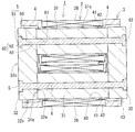
- FIG. 2 is a horizontal sectional view of the reactor of FIG.
- FIG. 3 is a horizontal sectional view of the reactor of the second embodiment.
- FIG. 4 is a horizontal sectional view of the reactor of the third embodiment.
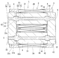
- FIG. 5 is a horizontal sectional view of the reactor of the fourth embodiment.
- Patent Document 1 it is possible to accurately connect a plurality of core pieces. Further, since the bolt members that connect the core pieces are arranged so as to penetrate all the core pieces and are not arranged outside the coils, it is possible to suppress the reactor from becoming large due to the bolt members. However, with the configuration of Patent Document 1, there is room for improvement in terms of productivity, and there is also a possibility that the magnetic characteristics may deteriorate.
- the inner core part is composed of a plurality of core pieces and gap members, it is necessary to provide through holes in each core piece and the gap member. Further, the work of aligning the core piece and the gap member and the work of penetrating the bolt member in alignment with the through holes of each member are complicated.
- the bolt member is arranged in the portion that becomes the magnetic path, and the magnetic characteristics of the reactor are not good. This is because the material of the bolt member of Patent Document 1 is selected in consideration of the strength of tightening by the bolt member, and is not considered to be selected in consideration of the magnetic characteristics of the reactor.
- the reactor of the present disclosure has excellent magnetic properties and can be manufactured with high productivity by a simple procedure.
- a coil having a winding portion A reactor comprising an inner core portion arranged inside the winding portion, and a magnetic core having an outer core portion arranged outside the winding portion,
- the magnetic core is A communication hole that penetrates the outer core portion and reaches the inner core portion,
- the composite material is formed by dispersing soft magnetic powder in resin.
- the inner core portion and the outer core portion are aligned, and the composite material is filled in the communication hole that penetrates the outer core portion and reaches the inner core portion.
- the softened resin of the composite material adheres to the communication hole, the communication hole and the connecting shaft of the composite material are fused over the entire length with almost no gap, and the outer core portion and the inner core portion are connected by the connecting shaft. ..
- the reactor can be completed only by filling the communication hole with the composite material, so that the productivity of the reactor can be improved.
- the magnetic characteristics required for the reactor are unlikely to deteriorate. This is because the connecting shaft that connects the inner core portion and the outer core portion is made of a composite material, so that the reduction in magnetic characteristics required for the magnetic core of the reactor is suppressed.
- Each of the inner core portion and the outer core portion may be in the form of a non-divided structure.
- Each of the inner core portion and the outer core portion may be a combination of divided pieces, but if the inner core portion and the outer core portion are integrally formed of a non-divided structure, the inner core portion and the outer portion at the time of manufacturing the reactor Positioning with the core part becomes easy. As a result, the productivity of the reactor can be improved.
- connection shaft may include a retaining portion that is hooked on the inner peripheral surface of the communication hole in the axial direction.
- the connecting shaft will not easily mechanically come off the magnetic core.
- the connection between the inner core portion and the outer core portion by the connecting shaft can be made stronger.
- the structure of the retaining portion is not particularly limited.
- the retaining portion may be formed by a thread-shaped irregularity formed on the outer peripheral surface of the connecting shaft.
- the connecting shaft includes a projecting portion that projects in a direction intersecting the axial direction,
- the retaining portion may be in the form of the protruding portion.
- the connecting shaft is a retaining part that consists of an overhanging part that extends in a direction that intersects the axial direction of the connecting part, it is possible to reliably prevent the connecting shaft from coming off the magnetic core.
- the overhanging portion include a thick shaft portion where the cross-sectional area of the connecting shaft is locally increased.
- an intersecting axis that intersects the axial direction of the connecting axis can be cited.
- ⁇ 5> As one form of the reactor of ⁇ 3> or ⁇ 4> above, An example is a form in which the retaining portion is formed inside the outer core portion.
- the retaining portion of the connecting shaft is formed inside the inner core portion, the inner core portion and the outer core portion can be connected more firmly.
- the overhanging part By forming the overhanging part so as to straddle the outer core part and the inner core part, it is possible to suppress an increase in reactor loss.
- a gap air gap
- the overhanging portion is formed across both core portions, the facing area of both core portions is reduced by the amount of the overhanging portion. As a result, it becomes difficult to form an air gap at the boundary between both core portions, so that it is possible to suppress an increase in reactor loss.
- the composite material contains a resin, it has better machinability than a powder compact formed by pressing soft magnetic powder. As shown in an embodiment described later, since a communication hole having a complicated shape may be formed especially in the inner core portion, it is preferable to form the inner core portion with a composite material having excellent machinability.
- the inner core part By configuring the inner core part with a composite material, it becomes easier to adjust the magnetic characteristics of the entire reactor. This is because the magnetic characteristics of the composite material can be easily adjusted by adjusting the content of the soft magnetic powder of the composite material. In particular, when the inner core portion and the outer core portion are independent moldings, there is only room for interposing the gap member between the inner core portion and the outer core portion, and the magnetic characteristics of the entire reactor are adjusted. hard. In contrast to this configuration, it is effective to configure the inner core portion with a composite material.
- An example is a form in which the outer core portion is made of a soft magnetic powder compact.
- the green compact easily increases the soft magnetic powder content, and by increasing the content, it is easy to increase the saturation magnetic flux density and relative permeability of the green compact.
- the inner core portion is made of a composite material and the outer core portion is made of a powder compact, a reactor having extremely excellent magnetic characteristics can be obtained.
- the reactor 1 shown in FIG. 1 is configured by combining a coil 2, a magnetic core 3 and a holding member 4.
- the magnetic core 3 includes an inner core portion 31 and an outer core portion 32.
- One of the features of the reactor 1 is that the inner core portion 31 and the outer core portion 32 are integrally formed of a non-divided structure, and the inner core portion 31 and the outer core portion 32 are connected by a connecting shaft 5 of a composite material. That is being done.
- each component provided in the reactor 1 will be described in detail.
- the coil 2 of the present embodiment includes a pair of winding portions 2A and 2B and a connecting portion 2R that connects the winding portions 2A and 2B.
- the winding portions 2A and 2B are formed in a hollow cylindrical shape with the same number of windings and the same winding direction, and are arranged in parallel so that their axial directions are parallel to each other.
- the coil 2 is manufactured by connecting the winding portions 2A and 2B which are manufactured by the separate windings 2w, but the coil 2 can be manufactured by using one winding 2w.
- Each winding part 2A, 2B of this embodiment is formed in a rectangular tube shape.
- the rectangular tube-shaped winding portions 2A and 2B are winding portions whose end faces have a quadrangular shape (including a square shape) with rounded corners.
- the winding parts 2A and 2B may be formed in a cylindrical shape.
- the cylindrical winding portion is a winding portion whose end surface shape is a closed curved surface shape (elliptical shape, perfect circle shape, race track shape, etc.).
- the coil 2 including the wound portions 2A and 2B is a covered wire having an insulating coating made of an insulating material on the outer periphery of a conductor such as a rectangular wire or a round wire made of a conductive material such as copper, aluminum, magnesium, or an alloy thereof.
- a conductor such as a rectangular wire or a round wire made of a conductive material such as copper, aluminum, magnesium, or an alloy thereof.
- the conductor is made of a copper rectangular wire (winding 2w), and the insulating rectangular wire made of enamel (typically polyamide imide) is wound edgewise to form each winding portion 2A, 2B is formed.
- Both ends 2a and 2b of the coil 2 are extended from the winding portions 2A and 2B and connected to a terminal member (not shown).
- the insulating coating such as enamel is peeled off at both ends 2a and 2b.
- an external device such as a power source for supplying electric power to the coil 2 is connected.
- the magnetic core 3 includes inner core portions 31, 31 arranged inside the winding portion 2A and the winding portion 2B, and outer core portions 32, 32 forming a closed magnetic path with the inner core portions 31, 31. , Is provided.
- the magnetic core 3 of this example has a gapless structure in which a gap member is not arranged between the inner core portion 31 and the outer core portion 32, but a structure including a gap member may be used.
- the inner core portion 31 is a portion of the magnetic core 3 along the axial direction of the winding portions 2A and 2B of the coil 2.
- both ends of the magnetic core 3 along the axial direction of the winding portions 2A and 2B project from the end faces of the winding portions 2A and 2B (FIG. 2).
- the protruding portion is also a part of the inner core portion 31.
- the end portion of the inner core portion 31 protruding from the winding portions 2A and 2B is inserted into a through hole 40 of the holding member 4 described later.
- the shape of the inner core portion 31 is not particularly limited as long as it is a shape that follows the inner shape of the winding portion 2A (2B).
- the inner core portion 31 of this example has a substantially rectangular parallelepiped shape.
- the inner core portion 31 is a non-divided, one-piece structure, which is one of the factors that facilitate the assembly of the reactor 1.
- the inner core portion 31 can also be configured by combining a plurality of split cores.
- the inner core portion 31 may be formed by interposing a gap plate between the split cores.
- the axial end surface 31e of the inner core portion 31 is in contact with the inner surface 32e of the outer core portion 32, which will be described later (FIG. 2).
- An adhesive may be interposed between the end surface 31e and the inner surface 32e, but it does not have to be provided. This is because the inner core portion 31 and the outer core portion 32 are connected by the connecting shaft 5, as described later.
- the peripheral surface 31s excluding the end surface 31e faces the inner peripheral surfaces of the winding portions 2A and 2B, but does not contact the inner peripheral surface, and the inner peripheral surface thereof. It is held in a position away from. This is because both the inner core portion 31 and the winding portions 2A and 2B mechanically engage with a holding member 4 described later, and the relative positions of the inner core portion 31 and the winding portions 2A and 2B are determined. Because it is.
- the inner core portion 31 of this example further includes an inner core hole 61.
- the inner core hole 61 of this example is a through hole that penetrates the inner core portion 31 in the axial direction.
- the inner core hole 61 has a uniform inner peripheral surface shape in the axial direction.
- the inner core hole 61 constitutes a part of the communication hole 6 described later.
- a connecting shaft 5 made of a composite material is arranged inside the inner core hole 61.
- the composite material is a material that can be a constituent material of the magnetic core 3 as described later. Therefore, the portion of the connecting shaft 5 arranged inside the inner core hole 61 may be considered as a part of the inner core portion 31.
- the inner core hole 61 of this example has a circular cross section orthogonal to the axial direction.
- the shape of the cross section of the inner core hole 61 is not particularly limited, and may be, for example, a polygonal shape such as a quadrangle or a pentagon.
- the axis of the inner core hole 61 of this example matches the axis of the inner core portion 31.
- the inner core hole 61 may be inclined with respect to the axial direction of the inner core portion 31.
- the cross-sectional area of the inner core hole 61 is not particularly limited.
- the cross-sectional area of the inner core portion 31 when the cross-sectional area of the inner core portion 31 is 100%, the cross-sectional area of the inner core hole 61 may be 5% or more and 30% or less.
- the area of the cross section of the inner core hole 61 with respect to the inner core portion 31 is preferably 10% or more and 25% or less, and more preferably 10% or more and 20% or less.
- the inner core hole 61 can be formed by a mold when the inner core portion 31 is molded. Further, the inner core hole 61 can also be formed by processing. In this case, the inner core hole 61 can be formed by forming a hole in the end surface 31e after forming the inner core portion 31 with a drill or the like.
- the outer core portion 32 is a portion of the magnetic core 3 arranged outside the winding portions 2A and 2B (FIG. 1).
- the shape of the outer core portion 32 is not particularly limited as long as it is a shape that connects the ends of the pair of inner core portions 31, 31.
- the outer core portion 32 of this example is a rectangular parallelepiped block body, but may have a substantially dome shape or a U shape when viewed from above.
- the outer core portion 32 is a non-divided structure and is one of the factors that facilitate the assembly of the reactor 1. Unlike the present example, the outer core portion 32 can also be configured by combining a plurality of split cores.
- the outer core portion 32 has an inner surface 32e facing the end surfaces of the winding portions 2A and 2B of the coil 2, an outer surface 32o opposite to the inner surface 32e, and a peripheral surface 32s.
- the inner surface 32e and the outer surface 32o are flat surfaces parallel to each other.
- the upper surface and the lower surface of the peripheral surface 32s are flat surfaces that are parallel to each other and orthogonal to the inner surface 32e and the outer surface 32o.
- two side surfaces are also parallel to each other and are flat surfaces orthogonal to the inner surface 32e and the outer surface 32o.
- the outer core portion 32 of this example further includes an outer core hole 62 that extends coaxially with the inner core hole 61.
- the outer core hole 62 of this example is a through hole whose one end side is opened to the outer surface 32o and the other end surface is opened to the inner surface 32e.
- Two outer core holes 62 are provided in one outer core portion 32. That is, the entire reactor 1 is provided with the four outer core holes 62.
- the outer core hole 62 of this example is a roughly T-shaped hole composed of a first hole portion h1 on the inner core portion 31 side and a second hole portion h2 on the outer surface 32o side.
- the first hole portion h1 is a hole having the same inner peripheral surface shape and the same cross-sectional area as the inner core hole 61.
- the second hole portion h2 is a hole having a larger cross-sectional area than the first hole portion h1.
- the cross-sectional area referred to here is the area of the cross section orthogonal to the axial direction of the outer core hole 62 (communication hole 6). Unlike this example, the cross-sectional area of the first hole portion h1 may be smaller or larger than the cross-sectional area of the inner core hole 61.
- the connecting shaft 5 made of a composite material is also arranged inside the outer core hole 62. Therefore, the portion of the connecting shaft 5 arranged inside the outer core hole 62 may be considered as a part of the outer core portion 32.
- the inner core portion 31 and the outer core portion 32 are composed of a powder compact formed by press-molding raw material powder containing soft magnetic powder, or a composite material compact formed by dispersing soft magnetic powder in resin. be able to.
- the core portions 31 and 32 may be hybrid cores in which the outer periphery of the powder compact is covered with the composite material.
- the core portions 31 and 32 may be a molded body of a composite material in which a gap plate such as alumina is embedded, or a mold core in which the core piece and the gap plate are connected and the outer periphery thereof is covered with resin. May be.
- a powder compact can be manufactured by filling raw material powder into a mold and pressurizing it. Because of the manufacturing method, it is easy to increase the content of the soft magnetic powder in the powder compact. For example, the content of the soft magnetic powder in the green compact can be more than 80% by volume, and more than 85% by volume. Therefore, in the case of a powder compact, it is easy to obtain the core portions 31 and 32 having high saturation magnetic flux density and high relative magnetic permeability.
- the relative magnetic permeability of the green compact can be 50 or more and 500 or less, and further 200 or more and 500 or less.
- the soft magnetic powder of the compacted body is an aggregate of soft magnetic particles composed of an iron group metal such as iron and its alloys (Fe-Si alloy, Fe-Ni alloy, etc.).
- An insulating coating made of phosphate or the like may be formed on the surface of the soft magnetic particles.
- the raw material powder may contain a lubricant or the like.
- a molded body of composite material can be manufactured by filling a mold with a mixture of soft magnetic powder and unsolidified resin and solidifying the resin. Due to the manufacturing method, the content of the soft magnetic powder can be easily adjusted in the composite material.
- the content of the soft magnetic powder in the composite material can be 30% by volume or more and 80% by volume or less. From the viewpoint of improving the saturation magnetic flux density and heat dissipation, the content of the magnetic powder is preferably 50% by volume or more, 60% by volume or more, and 70% by volume or more. Further, from the viewpoint of improving the fluidity in the manufacturing process, the content of the magnetic powder is preferably 75% by volume or less.
- the relative magnetic permeability of the molded body of the composite material can be 5 or more and 50 or less, and further 20 or more and 50 or less.
- the soft magnetic powder of the composite material can be the same as that used in the green compact.
- the resin contained in the composite material include a thermosetting resin, a thermoplastic resin, a room temperature curable resin, and a low temperature curable resin.
- the thermosetting resin include unsaturated polyester resin, epoxy resin, urethane resin, and silicone resin.
- the thermoplastic resin include polyphenylene sulfide resin, polytetrafluoroethylene resin, liquid crystal polymer, polyamide resin such as nylon 6 and nylon 66, polybutylene terephthalate resin, acrylonitrile butadiene styrene resin and the like.
- BMC Bit molding compound in which calcium carbonate or glass fiber is mixed with unsaturated polyester, millable silicone rubber, millable urethane rubber, etc.
- a non-magnetic and non-metal powder such as alumina or silica in addition to the soft magnetic powder and the resin, the heat dissipation property can be further enhanced.
- the content of the non-magnetic and non-metal powder is 0.2 mass% or more and 20 mass% or less, further 0.3 mass% or more and 15 mass% or less, and 0.5 mass% or more and 10 mass% or less. ..
- the holding member 4 shown in FIG. 2 is interposed between the end surfaces of the winding portions 2A and 2B of the coil 2 and the inner surface 32e of the outer core portion 32 of the magnetic core 3 and is arranged in the axial direction of the winding portions 2A and 2B. It is a member that holds the end surface and the outer core portion 32.
- the holding member 4 is typically made of an insulating material such as polyphenylene sulfide resin.
- the holding member 4 functions as an insulating member between the coil 2 and the magnetic core 3, and a positioning member for the inner core portion 31 and the outer core portion 32 with respect to the winding portions 2A and 2B.
- the two holding members 4 of this example have the same shape. Therefore, since the mold for manufacturing the holding member 4 can be shared, the productivity of the holding member 4 is excellent.
- the holding member 4 can be omitted.
- the holding member 4 includes a pair of through holes 40, 40, a pair of core support portions 41, a pair of coil storage portions 42, and one core storage portion 43.
- the through hole 40 penetrates in the thickness direction of the holding member 4, and the end portion of the inner core portion 31 is inserted into the through hole 40.
- the core support portion 41 is a tubular piece that projects from the inner peripheral surface of each through hole 40 toward the inner core portion 31 and supports the inner core portion 31.
- the coil housing portion 42 (FIG. 2) is a recess along the end surface of each winding portion 2A, 2B, and is formed so as to surround the core support portion 41, and the end surface and its vicinity are fitted.
- the core accommodating portion 43 is formed by partially recessing the surface of the holding member 4 on the outer core portion 32 side in the thickness direction, and the inner surface 32e of the outer core portion 32 and its vicinity are fitted.
- the end surface 31e of the inner core portion 31 fitted in the through hole 40 of the holding member 4 projects from the bottom surface of the core housing portion 43 (FIG. 3). Therefore, the end surface 31e of the inner core portion 31 and the inner surface 32e of the outer core portion 32 are in contact with each other.
- the reactor 1 of this example is provided with two connecting shafts 5.
- the one connecting shaft 5 connects the outer core portion 32 on the left side of the paper surface of FIG. 2, the inner core portion 31 housed in the winding portion 2A, and the outer core portion 32 on the right side of the paper surface.
- the other connecting shaft 5 connects the outer core portion 32 on the left side of the drawing, the inner core portion 31 housed in the winding portion 2B, and the outer core portion 32 on the right side of the drawing.
- the connecting shaft 5 is made of a composite material with which the communication hole 6 is filled. Therefore, the outer peripheral shape of the connecting shaft 5 has a shape that matches the inner peripheral shape of the communication hole 6.
- the resin contained in the composite material forming the connecting shaft 5 is fused to the inner peripheral surface of the communication hole 6 when the communication hole 6 is filled with the composite material. Therefore, the communication hole 6 and the connecting shaft 5 are in close contact with each other with almost no gap over the entire length, and the connecting shaft 5 connects the outer core portion 32 and the inner core portion 31.
- the communication hole 6 of this example is formed by connecting the inner core hole 61 and the outer core hole 62, as described above. Therefore, the communication hole 6 penetrates the one outer core portion 32, the inner core portion 31, and the other outer core portion 32. Both ends of the communication hole 6 are second holes h2 (a part of the outer core hole 62) having a larger cross-sectional area than the other portions. Therefore, the connecting shaft 5 of the composite material filled in the communication hole 6 includes the thin shaft portion 50 and the thick shaft portion 51.
- the thin shaft portion 50 is a portion corresponding to the first hole portion h1 of the outer core hole 62 and the inner core hole 61.
- the thick shaft portion 51 is a portion corresponding to the second hole portion h2 of the outer core hole 62.
- the end surface of the thick shaft portion 51 is flush with the outer surface 32o of the outer core portion 32.
- the thick shaft portion 51 is a projecting portion that projects beyond the thin shaft portion 50 in a direction intersecting the axial direction of the connecting shaft 5.
- An end surface of the thick shaft portion 51 on the inner surface 32e side is in contact with a step between the first hole portion h1 and the second hole portion h2 in the communication hole 6. That is, the thick shaft portion 51 functions as a retaining portion that is caught on the inner peripheral surface of the communication hole 6 in the axial direction of the connecting shaft 5, and prevents the connecting shaft 5 from coming off the magnetic core 3.
- the connection between the inner core portion 31 and the outer core portion 32 by the connecting shaft 5 can be strengthened.
- the outer core portion 32 is sandwiched between the thick shaft portion 51 of the connecting shaft 5 and the end surface 31e of the inner core portion 31, so that the outer core portion 32 does not fall off from the inner core portion 31.
- the inner core portion 31 and the outer core portion 32 can be directly coupled without any additional configuration other than the coupling shaft 5.
- the composition of the composite material forming the connecting shaft 5 can be appropriately selected.
- the composition of the composite material forming the connecting shaft 5 may be the same as or different from the composition of the composite material forming the inner core portion 31. It may be. If the connecting shaft 5 and the inner core portion 31 have the same composition, it is possible to suppress unevenness in the magnetic characteristics of the inner core portion 31 including the connecting shaft 5.
- the resin content of the connecting shaft 5 can be made larger than the resin content of the inner core portion 31. By doing so, it becomes easy to fill the communication hole 6 with the composite material. In that case, it is preferable that the content of the soft magnetic powder in the connecting shaft 5 does not become too low in order to suppress the deterioration of the magnetic characteristics of the connecting shaft 5.
- the resin content of the connecting shaft 5 may be 50% by volume or more and 60% by volume or less, and the soft magnetic powder content may be 40% by volume or more and 50% by volume or less.
- the resin content of the connecting shaft 5 may be smaller than the resin content of the inner core portion 31.
- the content of the soft magnetic powder of the connecting shaft 5 is made larger than the content of the soft magnetic powder of the inner core portion 31. Since the connecting shaft 5 is located at the center of the magnetic path in the inner core portion 31, it is possible to improve the magnetic characteristics of the magnetic core 3 by improving the magnetic characteristics of the connecting shaft 5.
- the resin content of the connecting shaft 5 may be 30% by volume or more and 40% by volume or less, and the soft magnetic powder content may be 60% by volume or more and 70% by volume or less.
- the composite material When filling the communication hole 6 with the composite material, the composite material may be filled only from one end side of the communication hole 6, or the composite material may be filled from one end side and the other end side.
- the reactor 1 of this example can be used as a constituent member of a power conversion device such as a bidirectional DC-DC converter mounted in an electric vehicle such as a hybrid vehicle, an electric vehicle, or a fuel cell vehicle.
- the reactor 1 of this example can be used while being immersed in a liquid refrigerant.
- the liquid refrigerant is not particularly limited, but when the reactor 1 is used in a hybrid vehicle, ATF (Automatic Transmission Fluid) or the like can be used as the liquid refrigerant.
- a fluorine-based inert liquid such as Fluorinert (registered trademark), a CFC-based refrigerant such as HCFC-123 or HFC-134a, an alcohol-based refrigerant such as methanol or alcohol, or a ketone-based refrigerant such as acetone is used as a liquid refrigerant.
- a fluorine-based inert liquid such as Fluorinert (registered trademark)
- a CFC-based refrigerant such as HCFC-123 or HFC-134a
- an alcohol-based refrigerant such as methanol or alcohol
- a ketone-based refrigerant such as acetone
- the reactor 1 of this example can be manufactured with high productivity by a simple procedure. This is because the inner core portion 31 and the outer core portion 32 are both integrally formed with a non-divided structure, so that the inner core portion 31 and the outer core portion 32 can be easily aligned when the reactor 1 is manufactured. Further, when the inner core portion 31 and the outer core portion 32 are aligned and the communication hole 6 penetrating the outer core portion 32 and the inner core portion 31 is filled with the composite material, the resin of the composite material melts into the communication hole 6. To wear.
- the communication hole 6 and the connecting shaft 5 of the composite material come into close contact with each other over the entire length with almost no gap, and the connecting shaft 5 connects the outer core portion 32 and the inner core portion 31.
- the fact that the reactor 1 can be completed only by filling the communication holes 6 with the composite material also contributes to the improvement of the productivity of the reactor 1.
- the magnetic properties required for the reactor 1 are unlikely to deteriorate. This is because the connecting shaft 5 that connects the inner core portion 31 and the outer core portion 32 is made of a composite material, so that the deterioration of the magnetic characteristics required for the magnetic core 3 of the reactor 1 is suppressed.
- the reactor 1 of this example has four independent communication holes 6.
- Each communication hole 6 has a role of connecting one inner core portion 31 and one outer core portion 32.
- the communication hole 6 in this example is composed of an inner core hole 61 and an outer core hole 62.
- the shape of the outer core hole 62 is the same as that of the first embodiment.
- the inner core hole 61 is formed in a substantially T-shape composed of the third hole portion h3 and the fourth hole portion h4.
- the third hole portion h3 is a short hole having an inner shape that matches the first hole portion h1 of the outer core hole 62.
- the fourth hole portion h4 is a hole that extends in a direction intersecting with the third hole portion h3 and opens on the peripheral surface 31s of the inner core portion 31.
- the fourth hole portion h4 of this example extends in a direction orthogonal to the axial direction of the third hole portion h3 (that is, the axial direction of the inner core portion 31). The entire opening of the fourth hole portion h4 is covered by the core support portion 41 of the holding member 4.
- the substantially T-shaped inner core hole 61 can be formed, for example, as follows. First, the fourth hole h4 that penetrates the peripheral surface 31s of the inner core portion 31 is formed by a drill or the like. Then, a third hole h3 reaching the fourth hole h4 is formed by cutting from the end surface 31e of the inner core 31 in the axial direction of the inner core 31 with a drill or the like. When the inner core portion 31 is made of a composite material, both holes h3 and h4 can be formed by using a core that is pulled out in the axial direction of the inner core portion 31 and a core that is pulled out in the orthogonal direction.
- the composite material When the composite material is filled from a position opening to the outer surface 32o of the communication hole 6, the composite material enters the fourth hole portion h4 from the outer core hole 62 through the third hole portion h3, and enters the fourth hole portion h4. The part that has entered becomes the overhanging part (prevention part) of the connecting shaft 5. At this time, since the opening of the fourth hole portion h4 is covered with the core support portion 41, the composite material may leak from the opening of the fourth hole portion h4 to the inside of the winding portions 2A and 2B and the core housing portion 43. There is no.
- the reactor 1 of this example can also obtain the same effect as the reactor 1 of the first embodiment. Further, according to the reactor 1 of the present example, the connecting shaft 5 is almost never pulled out from the inner core portion 31, so that the inner core portion 31 and the outer core portion 32 can be connected more firmly.
- the reactor 1 of this example has four independent communication holes 6.
- the shape of the outer core hole 62 of the communication hole 6 of this example is the same as that of the first embodiment.
- the inner core hole 61 has female screw-shaped irregularities formed on its inner peripheral surface. Therefore, when the connecting shaft 5 is filled with the composite material, the outer periphery of the portion of the thin shaft portion 50 of the connecting shaft 5 arranged in the inner core hole 61 becomes the screw-shaped portion 5m. The screw-shaped portion 5m is caught by the uneven shape of the inner peripheral surface of the inner core hole 61 and functions as a retaining portion of the connecting shaft 5.
- the thread shape of the inner peripheral surface of the inner core hole 61 can be formed by processing the inner peripheral surface of the circular hole with a tap or the like.
- the inner core portion 31 is formed of a composite material, it is possible to form the above-mentioned thread shape by using a male screw-shaped core.
- the inner core hole 61 having the thread-shaped inner peripheral surface is formed by pulling out the inner core portion 31 while rotating the core.
- the reactor 1 of this example can also obtain the same effect as the reactor 1 of the first embodiment. According to the reactor 1 of this example, there is an advantage that the formation of the inner core hole 61 is relatively easy.
- a modification of this example is to form the screw-shaped portion 5m over the entire length of the connecting shaft 5.
- Embodiment 4 the reactor 1 in which the overhanging portion (thick shaft portion 51) of the connecting shaft 5 is formed so as to straddle the outer core portion 32 and the inner core portion 31 will be described with reference to FIG. 5.
- the communication hole 6 filled with the connecting shaft 5 of the present example has one outer core portion 32, one inner core portion 31, and the other outer core portion 32, as in the reactor 1 of the first embodiment. Penetrate through.
- the cross-sectional area of the first hole portion h1 on the inner core portion 31 side is larger than the cross-sectional area of the second hole portion h2 on the outer surface 32o side.
- the inner core hole 61 is composed of a fifth hole portion h5 extending over substantially the entire axial length of the inner core portion 31, and a sixth hole portion h6 formed at one end and the other end of the fifth hole portion h5.
- the inner peripheral surface shape and cross-sectional area of the fifth hole portion h5 are the same as the inner peripheral surface shape and cross-sectional area of the second hole portion h2.
- the inner peripheral surface shape and the sectional area of the sixth hole portion h6 are the same as the inner peripheral surface shape and the sectional area of the first hole portion h1.
- the inner core hole 61 and the outer core hole 62 having the above shapes can be formed, for example, as follows. First, a through hole is formed in the inner core portion 31 (outer core portion 32) with a drill having a small diameter. Next, a short hole is formed in the end surface 31e (inner surface 32e) with a drill having a large diameter. In this case, the hole formed by the small diameter drill becomes the fifth hole portion h5 (second hole portion h2), and the hole formed by the thick diameter drill becomes the sixth hole portion h6 (first hole portion h1). ).
- the connecting shaft 5 of the composite material filled in the communication hole 6 includes two thick shaft portions 51 in the axial direction of the thin shaft portion 50.
- the thick shaft portion 51 is made of a composite material that fills the space formed by the first hole portion h1 and the sixth hole portion h6. Therefore, the thick shaft portion 51 is formed so as to straddle the inner core portion 31 and the outer core portion 32.
- the reactor 1 of the present example in addition to obtaining the same effect as the reactor 1 of the first embodiment, it is possible to obtain the effect of reducing the leakage magnetic flux from the boundary between the inner core portion 31 and the outer core portion 32.
- the end surface 31e of the inner core portion 31 and the inner surface 32e of the outer core portion 32 are in contact with each other.
- a plurality of local gaps may be formed between the end surface 31e and the inner surface 32e. If the area of the cross section of the thick shaft portion 51 is increased, the area where the end surface 31e and the inner surface 32e face each other can be reduced in the first place, so that the number of local gaps can be reduced.
- the leakage magnetic flux of the reactor 1 can be reduced, and the magnetic loss of the reactor 1 can be reduced.
- the reactor 1 may be manufactured by appropriately combining the configurations related to the connecting shaft 5 of the first to fourth embodiments. For example, it is possible to form female screw-shaped irregularities on the inner peripheral surface of the inner core hole 61 of the first embodiment shown in FIG. Further, in the configuration of the fourth embodiment, the thick shaft portion 51 may be formed on the outer surface 32o side of the outer core portion 32. There is a possibility that the connection between the inner core portion 31 and the outer core portion 32 can be made stronger by combining a plurality of configurations related to the connecting shaft 5.
Landscapes
- Engineering & Computer Science (AREA)
- Power Engineering (AREA)
- Chemical & Material Sciences (AREA)
- Composite Materials (AREA)
- Dispersion Chemistry (AREA)
- Manufacturing & Machinery (AREA)
- Physics & Mathematics (AREA)
- Spectroscopy & Molecular Physics (AREA)
- Housings And Mounting Of Transformers (AREA)
- Insulating Of Coils (AREA)
- Power Conversion In General (AREA)
Priority Applications (2)
| Application Number | Priority Date | Filing Date | Title |
|---|---|---|---|
| CN201980078738.0A CN113168960B (zh) | 2018-12-03 | 2019-11-27 | 电抗器 |
| US17/296,366 US12080463B2 (en) | 2018-12-03 | 2019-11-27 | Reactor |
Applications Claiming Priority (2)
| Application Number | Priority Date | Filing Date | Title |
|---|---|---|---|
| JP2018-226542 | 2018-12-03 | ||
| JP2018226542A JP7106058B2 (ja) | 2018-12-03 | 2018-12-03 | リアクトル |
Publications (1)
| Publication Number | Publication Date |
|---|---|
| WO2020116293A1 true WO2020116293A1 (ja) | 2020-06-11 |
Family
ID=70975067
Family Applications (1)
| Application Number | Title | Priority Date | Filing Date |
|---|---|---|---|
| PCT/JP2019/046467 Ceased WO2020116293A1 (ja) | 2018-12-03 | 2019-11-27 | リアクトル |
Country Status (4)
| Country | Link |
|---|---|
| US (1) | US12080463B2 (https=) |
| JP (1) | JP7106058B2 (https=) |
| CN (1) | CN113168960B (https=) |
| WO (1) | WO2020116293A1 (https=) |
Families Citing this family (3)
| Publication number | Priority date | Publication date | Assignee | Title |
|---|---|---|---|---|
| JP7630767B2 (ja) * | 2021-03-19 | 2025-02-18 | 株式会社オートネットワーク技術研究所 | リアクトル、コンバータ、及び電力変換装置 |
| JP7630768B2 (ja) | 2021-03-29 | 2025-02-18 | 株式会社オートネットワーク技術研究所 | コア片、リアクトル、コンバータ、及び電力変換装置 |
| FR3152633A1 (fr) * | 2023-08-31 | 2025-03-07 | Safran | Noyau magnetique a fermeture optimisee |
Citations (6)
| Publication number | Priority date | Publication date | Assignee | Title |
|---|---|---|---|---|
| JP2013026492A (ja) * | 2011-07-22 | 2013-02-04 | Ishikawa Electric Co Ltd | リアクトル及びこのリアクトルを搭載したパワーコンディショナ |
| JP2014138012A (ja) * | 2013-01-15 | 2014-07-28 | Toyota Motor Corp | 冷却器付きリアクトル |
| JP2015032626A (ja) * | 2013-07-31 | 2015-02-16 | 新光電気工業株式会社 | コイル基板及びその製造方法、インダクタ |
| JP2017212346A (ja) * | 2016-05-25 | 2017-11-30 | 株式会社オートネットワーク技術研究所 | リアクトル、およびリアクトルの製造方法 |
| JP2017224851A (ja) * | 2014-09-17 | 2017-12-21 | 株式会社オートネットワーク技術研究所 | 複合材料、磁気部品、及びリアクトル |
| JP2018107341A (ja) * | 2016-12-27 | 2018-07-05 | トヨタ自動車株式会社 | リアクトルのコアの製造方法 |
Family Cites Families (8)
| Publication number | Priority date | Publication date | Assignee | Title |
|---|---|---|---|---|
| US3636345A (en) * | 1969-10-27 | 1972-01-18 | Joel Hirschel | Mass spectrometer detector arrays |
| JP5096705B2 (ja) * | 2006-07-24 | 2012-12-12 | 株式会社日立産機システム | クローティース型同期機 |
| JP2008182075A (ja) * | 2007-01-25 | 2008-08-07 | Sumitomo Electric Ind Ltd | リアクトル |
| JP5983942B2 (ja) * | 2013-01-25 | 2016-09-06 | 住友電気工業株式会社 | リアクトル、コンバータ、及び電力変換装置 |
| JP2015050397A (ja) * | 2013-09-03 | 2015-03-16 | 住友電気工業株式会社 | リアクトルの製造方法、およびリアクトル |
| JP3195212U (ja) | 2014-10-22 | 2015-01-08 | スミダコーポレーション株式会社 | リアクトル |
| CN205692667U (zh) * | 2016-03-31 | 2016-11-16 | 湖南谦益电子科技有限公司 | 一种多层组合式铁氧体磁芯 |
| JP6474469B2 (ja) * | 2016-09-08 | 2019-02-27 | ファナック株式会社 | 第一端板および第二端板を備えたリアクトル |
-
2018
- 2018-12-03 JP JP2018226542A patent/JP7106058B2/ja active Active
-
2019
- 2019-11-27 US US17/296,366 patent/US12080463B2/en active Active
- 2019-11-27 WO PCT/JP2019/046467 patent/WO2020116293A1/ja not_active Ceased
- 2019-11-27 CN CN201980078738.0A patent/CN113168960B/zh active Active
Patent Citations (6)
| Publication number | Priority date | Publication date | Assignee | Title |
|---|---|---|---|---|
| JP2013026492A (ja) * | 2011-07-22 | 2013-02-04 | Ishikawa Electric Co Ltd | リアクトル及びこのリアクトルを搭載したパワーコンディショナ |
| JP2014138012A (ja) * | 2013-01-15 | 2014-07-28 | Toyota Motor Corp | 冷却器付きリアクトル |
| JP2015032626A (ja) * | 2013-07-31 | 2015-02-16 | 新光電気工業株式会社 | コイル基板及びその製造方法、インダクタ |
| JP2017224851A (ja) * | 2014-09-17 | 2017-12-21 | 株式会社オートネットワーク技術研究所 | 複合材料、磁気部品、及びリアクトル |
| JP2017212346A (ja) * | 2016-05-25 | 2017-11-30 | 株式会社オートネットワーク技術研究所 | リアクトル、およびリアクトルの製造方法 |
| JP2018107341A (ja) * | 2016-12-27 | 2018-07-05 | トヨタ自動車株式会社 | リアクトルのコアの製造方法 |
Also Published As
| Publication number | Publication date |
|---|---|
| US20210398735A1 (en) | 2021-12-23 |
| JP7106058B2 (ja) | 2022-07-26 |
| CN113168960B (zh) | 2023-04-07 |
| US12080463B2 (en) | 2024-09-03 |
| CN113168960A (zh) | 2021-07-23 |
| JP2020092117A (ja) | 2020-06-11 |
Similar Documents
| Publication | Publication Date | Title |
|---|---|---|
| JP6478065B2 (ja) | リアクトル、およびリアクトルの製造方法 | |
| WO2020116293A1 (ja) | リアクトル | |
| US12119167B2 (en) | Reactor | |
| US11935687B2 (en) | Reactor | |
| WO2019168152A1 (ja) | リアクトル、及びリアクトルの製造方法 | |
| US11776733B2 (en) | Reactor including a magnetic core | |
| US12002612B2 (en) | Reactor | |
| US11521781B2 (en) | Reactor | |
| US20210118606A1 (en) | Reactor | |
| WO2019168151A1 (ja) | リアクトル | |
| JP2019212779A (ja) | リアクトル | |
| JP7124635B2 (ja) | リアクトル | |
| WO2019235186A1 (ja) | リアクトル | |
| US11145451B2 (en) | Reactor |
Legal Events
| Date | Code | Title | Description |
|---|---|---|---|
| 121 | Ep: the epo has been informed by wipo that ep was designated in this application |
Ref document number: 19892227 Country of ref document: EP Kind code of ref document: A1 |
|
| NENP | Non-entry into the national phase |
Ref country code: DE |
|
| 122 | Ep: pct application non-entry in european phase |
Ref document number: 19892227 Country of ref document: EP Kind code of ref document: A1 |