WO2020107449A1 - 编码方法、编码器以及计算机存储介质 - Google Patents
编码方法、编码器以及计算机存储介质 Download PDFInfo
- Publication number
- WO2020107449A1 WO2020107449A1 PCT/CN2018/118701 CN2018118701W WO2020107449A1 WO 2020107449 A1 WO2020107449 A1 WO 2020107449A1 CN 2018118701 W CN2018118701 W CN 2018118701W WO 2020107449 A1 WO2020107449 A1 WO 2020107449A1
- Authority
- WO
- WIPO (PCT)
- Prior art keywords
- encoder
- bit rate
- image frame
- previous time
- virtual buffer
- Prior art date
- Legal status (The legal status is an assumption and is not a legal conclusion. Google has not performed a legal analysis and makes no representation as to the accuracy of the status listed.)
- Ceased
Links
Images

Classifications
-
- H—ELECTRICITY
- H04—ELECTRIC COMMUNICATION TECHNIQUE
- H04N—PICTORIAL COMMUNICATION, e.g. TELEVISION
- H04N19/00—Methods or arrangements for coding, decoding, compressing or decompressing digital video signals
- H04N19/10—Methods or arrangements for coding, decoding, compressing or decompressing digital video signals using adaptive coding
- H04N19/102—Methods or arrangements for coding, decoding, compressing or decompressing digital video signals using adaptive coding characterised by the element, parameter or selection affected or controlled by the adaptive coding
- H04N19/124—Quantisation
Definitions
- the embodiments of the present application relate to the technical field of bit rate control in video encoding, and in particular, to an encoding method, an encoder, and a computer storage medium.
- Video coding also known as video compression, compresses original video sources with a large amount of time and space redundancy through techniques such as quantization, transformation, and entropy coding to minimize the space or bandwidth required for storage or transmission.
- video compression compresses original video sources with a large amount of time and space redundancy through techniques such as quantization, transformation, and entropy coding to minimize the space or bandwidth required for storage or transmission.
- the code rate control is to change the code rate output by the encoder by adjusting the coding parameters, so as to meet the code rate requirements set by the user.
- rate control is the most important technical field in the field of video coding; the core problem of rate control is to establish the relationship model between the rate and the encoding parameters, that is, how to determine the encoding parameters according to the target rate to ensure that the Under certain video quality, the control is stable and the error is small enough.
- the video encoding process if the code rate control is not performed, then usually the video encoding will be encoded with preset encoding parameters.
- the number of output bits of each frame of image fluctuates and is not controlled.
- the source video contains a lot of time and space redundancy.
- the purpose of encoding is to eliminate these redundancy as much as possible, but usually these redundancy distributions in various video sequences are very uneven or even no.
- the regularity causes the encoder output bit to fluctuate greatly.
- encoders generally use variable-length coding to encode coefficients to save codewords, and variable-length coding designs codewords based on the probability of symbol appearance. The greater the probability of occurrence, the shorter the codeword.
- bit rate control is particularly important in video coding.
- the rate control algorithm calculates a set of coding parameters for each macroblock according to the content characteristics of each macroblock, thereby obtaining a more accurate Control effect; on the contrary, the use of image group level or frame level code rate control, in the case of image group level code rate control, the main idea is: calculate the total bit demand of each image group and the bit allocation of the remaining uncoded frames, And determine the actual quantization parameters of each image group.
- Frame-level bit rate control is a bit more complicated.
- Frame B is not referenced by other frames, and its quantization parameters pass the quantization parameters of adjacent frames.
- the P frame will be referenced by multiple frames in the future, which has a greater impact, so it needs to be accurately calculated.
- the linear tracking theory is used to calculate two sets of target bits for the current frame, and then the weighted average is calculated to obtain the number of bits allocated to the current frame, and then the linear model is used to predict the MAD complexity of the current frame and bring into the two
- the second-rate distortion model obtains the quantization parameters of the current frame.
- the rate control at the macroblock level the main idea is similar to the rate control at the frame level. First, the number of allocated bits is predicted, then the MAD is predicted, and finally the quantization parameter of the current macroblock is calculated by the second rate distortion model.
- HEVC High Efficiency Video Coding
- HEVC High Efficiency Video Coding
- the core content is to innovatively propose the R- ⁇ relation model, which is used to calculate the Lagrangian multiplier ⁇ , and then directly bring the Lagrangian multiplier ⁇ into an empirical formula to calculate the quantitative parameters.
- AVS2, Audio, Video, and Standard 2 a fuzzy logic-based control theory is adopted, and a fuzzy control lookup table is established in advance.
- the buffer state is established, and the table is directly looked up to obtain the change of the quantization parameter, and then the quantization parameter used for encoding the next frame is obtained.
- the embodiments of the present application desire to provide an encoding method, an encoder, and a computer storage medium, which can improve the encoding performance of the encoder when encoding.
- an embodiment of the present application provides a capacitive encoding method, which is applied to an encoder, and the method includes:
- the target performance parameter of the encoder determine the change amount of the performance parameter of the encoder at the current time and the previous time
- an encoder in a second aspect, provides an encoder.
- the encoder includes:
- a first acquiring unit configured to acquire the performance parameter of the encoder at the last moment and the quantization parameter QP value of the image frame to be encoded at the last moment;
- a first determining unit configured to determine the change amount of the performance parameter of the encoder at the current time and the previous time according to the target performance parameter of the encoder
- the second determining unit is configured to determine that the image frame to be encoded is based on the change amount of the performance parameter, the performance parameter of the encoder at the previous time, and the QP value of the image frame to be encoded at the previous time QP value at the current moment;
- the encoding unit is configured to encode the image frame to be encoded at the current time according to the QP value of the image frame to be encoded at the current time.
- an encoder includes:
- an embodiment of the present application provides a computer storage medium that stores executable instructions.
- the processor executes the first aspect. The encoding method described.
- An embodiment of the present application provides an encoding method, an encoder, and a computer storage medium.
- the method is applied to an encoder.
- the method includes: first, acquiring the performance parameters of the encoder at the previous moment and the image frame to be encoded are on the The QP value at a moment, according to the target performance parameter of the encoder, determines the amount of change in the performance parameter of the encoder at the current time and the previous time, so that you can know the amount of change in the performance parameter at the current time and the previous time, and then according to The amount of change in performance parameters, the performance parameter of the encoder at the previous time, and the QP value of the image frame to be encoded at the previous time, determine the QP value of the image frame to be encoded at the current time, that is, the amount of change in the performance parameter, encoding
- the performance parameter of the device at the previous moment and the QP value of the image frame to be encoded at the previous moment determine the QP value of the image frame to be encoded at the current moment,
- the QP value of the resulting encoded image frame at the current time is more accurate.
- the image frame to be encoded is encoded at the current moment; making the encoding process not only uses the preset encoding parameters, but also considers the amount of change in the encoder performance parameters, which is conducive to improving the performance of the encoding process The control precision of the parameters, thereby improving the encoding performance in the encoding process.
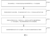
- FIG. 1 is a schematic flowchart of an optional encoding method provided by an embodiment of this application.
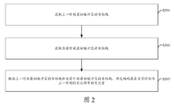
- FIG. 2 is a schematic flowchart of another optional encoding method provided by an embodiment of the present application.
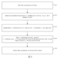
- FIG. 3 is a schematic flowchart of another alternative encoding method provided by an embodiment of the present application.
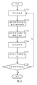
- FIG. 5 is a schematic flowchart of an alternative example of an encoding method provided by an embodiment of this application.
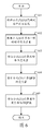
- FIG. 6 is a schematic flowchart of another optional example of the encoding method provided by the embodiment of the present application.
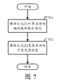
- FIG. 7 is a schematic flowchart of another optional example of the encoding method provided by the embodiment of the present application.
- FIG. 8 is a simulation diagram of the filling degree of the virtual buffer zone under the AI coding structure provided by the embodiment of the present application.
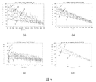
- FIG. 9 is a simulation diagram of the filling degree of the virtual buffer under the LD coding structure provided by the embodiment of the present application.
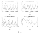
- FIG. 10 is a simulation diagram of the filling degree of the virtual buffer under the RA coding structure provided by the embodiment of the present application.
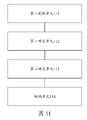
- FIG. 11 is a schematic structural diagram 1 of an encoder provided by an embodiment of the present application.
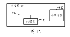
- FIG. 12 is a second structural diagram of an encoder provided by an embodiment of the present application.
- FIG. 1 is a schematic flowchart of an optional encoding method provided by an embodiment of the present application.
- the encoding method may include:
- the performance parameter includes any one of the following: the output rate parameter of the image frame, the output quality parameter of the image frame, or the output time parameter of the image frame.
- the target performance parameter is the target output bit rate
- the target output bit rate of the encoder is obtained, for example, the target output bit rate of the encoder set by the user is received. It should be noted here that the target output bit rate may also be referred to as the target code rate;
- the target bit rate of the encoder is preset by the user, and the user can set the target bit rate (TBR, Target, BitRate) of the encoder according to their own needs.
- the unit of TBR is bits per second (bps, bit per second).
- the embodiments of the present application may be performed in units of bit per pixel (bpp, bit per pixel) Characterization of the bit rate, so that the target bit rate can be converted into a target bit per pixel (T bpp , Target bit per pixel), the conversion method of the target bit rate can be calculated by the following formula:
- FPS is the frame rate of the original video
- W and H are the width and height of the original video, respectively.
- the target code rate can be converted into the target bit per pixel, and the target code rate referred to in the embodiments of the present application is expressed by the target bit per pixel.
- R is the encoder output bit rate
- T bpp is the target code rate
- S102 According to the target performance parameter of the encoder, determine the change amount of the performance parameter of the encoder at the current time and the previous time;
- S102 may include: determining the change amount of the output bit rate of the encoder at the current time and the previous time according to the target output bit rate of the encoder.
- FIG. 2 is a schematic flowchart of another alternative encoding method provided by an embodiment of the present application.
- S102 may include:
- S203 According to the target line of the virtual buffer at the previous time and the target line of the virtual buffer at the current time, determine the amount of change in the output bit rate of the encoder between the current time and the previous time;
- the virtual buffer is used to record the value of the encoder's output bit rate exceeding the target output bit rate.
- S202 may include:
- the target line of the virtual buffer at the current moment is determined according to the encoding structure type of the image frame to be encoded at the current moment and the target output bit rate of the encoder.
- the coding structure of the image frame can be roughly divided into three types, which are the coding structure in the full frame (AI, All Intra), the coding structure in low latency (LD, Low Delay), and the random access (RA, Random) Access) coding structure.
- AI All Intra
- LD low latency
- RA Random Access
- the target line of the virtual buffer at the previous time and the target line of the virtual buffer at the current time are determined for different coding structures.
- the embodiment of the present application introduces a virtual buffer, assuming that the traffic flowing into the virtual buffer is the bit rate output by the encoder in real time, and the traffic flowing out of the virtual buffer is the target code rate, So, in this process, it is assumed that the virtual buffer will keep changing dynamically, where the remaining flow of the virtual buffer is called the current virtual buffer fullness (CBF, Current Buffer Fullness); or, because each frame output may exist e t , causing the bits output by the encoder to exceed the target code rate and stay at the encoding end (the retention number can be a negative value, indicating that the output bit rate of the encoder is less than the target code rate).
- CBF Current Buffer Fullness
- the filling level of the virtual buffer is Among them, the filling degree of the virtual buffer can be calculated by the following formula:
- t represents the moment, because of the different coding structure, the dynamic change process of CBF has a big difference, usually the number of bits required to encode I frame is the most, P frame is next, and B frame is the least bit.
- the target code rate which determines the target line of the virtual buffer at the current moment, may include:
- the coding structure type of the image frame to be coded at the current moment is the AI structure, determine that the target lines of the virtual buffer at the current moment are all zero;
- the first preset formula is called to determine the target line of the virtual buffer at the current moment
- the second preset formula is called based on the target output bit rate to determine the target line of the virtual buffer at the current moment.
- the ideal goal of rate control is to let the CBF update In the process, it is as close to 0 as possible, so in the AI structure line, the target line of the virtual buffer is always 0, and the target line of the virtual buffer (TBL, Target BitLine) can be expressed by the following formula:
- the output error e of the encoder is calculated by formula (3):
- TBL represents the target line of the virtual buffer
- TFs represents the total number of encoded frames, that is, the above formula (3) and formula (6) are the first preset formulas.
- the first frame is an I frame
- the output bit rate is often several times or even tens of times the target bit rate, resulting in the CBF will be much higher after encoding the first I frame, and then It is impossible for the P frame to pull this high back to 0 immediately. Even if it can, it will cause the subsequent P frame to be of poor coding quality. When it is referenced, this error will be further amplified, resulting in serious distortion of the entire sequence . In this case, the height of the first I frame slowly drops to 0, which can make the distortion of the subsequent P frame not too large; where the first I frame is the starting frame of a sequence.
- the above formula (6) shows that under the LD structure, the first I-frame can not be controlled without incremental feedback, and its target line is the bit rate error of the first I-frame, and then this decrease is slowly reduced until the end One frame is zeroed.
- the output error e of the encoder is calculated by the above formula (3).
- the filling degree CBF of the virtual buffer is calculated by the above formula (4).
- TBL represents the target line of the virtual buffer
- IP represents the number of frames contained in each I frame period
- subscript I represents the coding sequence of I frames in the current I frame period
- I-Picture represents I frames
- Others represents non-I Frame, that is, the above formula (3), formula (4) and formula (7) are the second preset formula.
- the coding structure and the reference structure are slightly more complicated than the LD. I-frames will appear periodically. The sequence of the sequence is inconsistent with the coding order. When referring, there is a backward reference, and some frames There will be cases where it is not referenced. But ignoring these complicated situations, we can simply treat the situation between adjacent I frames as an LD structure.
- the formula (7) indicates that each I frame period is similar to the LD structure, and in the I frame period, the height is slowly reduced to 0.
- the following cycle non-first cycle required TBL I frame errors occurring when the end of a cycle before adding, when said CBF t-1 represents the end of an encoded IP
- the degree of filling of the virtual buffer, so when encoding the first IP, CBF t-1 0.
- FIG. 3 is a schematic flowchart of another alternative encoding method provided by an embodiment of the present application.
- S203 may include:
- S302 Determine the error of the virtual buffer at the previous time according to the filling level of the virtual buffer at the current time and the target line of the virtual buffer at the previous time;
- S303 Determine the output error of the encoder at the previous time according to the output bit rate of the encoder at the previous time and the target output bit rate;
- S305 Call the third preset formula to update the filling level of the virtual buffer at the current moment.
- S304 may include:
- the encoder uses the target line of the virtual buffer at the current time, subtract the target line of the virtual buffer at the previous time, subtract the error of the virtual buffer at the previous time, and subtract the output error of the encoder at the previous time, and determine as The encoder outputs the amount of change in the bit rate between the current time and the previous time.
- the error E of the virtual buffer after having the target line of the virtual buffer and the filling degree of the virtual buffer, the error E of the virtual buffer can be defined, and the error E of the virtual buffer can be calculated by the following formula:
- the third preset formula, formula (4) is called to update the filling level of the current virtual buffer.
- the above-mentioned a, b and c are empirical weight parameters.
- the amount of change ⁇ R in the output bit rate of the encoder at the previous time and the current time can be determined by the above formula (10) or formula (11).
- S103 Determine the QP value of the image frame to be encoded at the current time according to the amount of change in the performance parameter, the performance parameter of the encoder at the previous time, and the QP value of the image frame to be encoded at the previous time;
- the QP value can be represented by Q, and the Lagrangian multiplier and quantization parameter need to be calculated through ⁇ R feedback.
- the key to calculating both is to find the relationship between the connection bit rate, Lagrangian multiplier and quantization parameter.
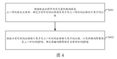
- FIG. 4 is a schematic flowchart of yet another alternative encoding method provided by an embodiment of the present application.
- S104 may include:
- S401 Determine the ratio of the Lagrangian multiplier at the current time to the Lagrangian multiplier at the previous time according to the change in the output bit rate and the output bit rate of the encoder at the previous time;
- S402 Determine the QP value of the image frame to be encoded at the current time according to the ratio of the Lagrange multiplier at the current time to the Lagrange multiplier at the previous time and the QP value of the image frame to be encoded at the previous time.
- the R- ⁇ model can be expressed by the following formula:
- S401 may include:
- ⁇ ⁇ can be expressed by the following formula:
- ⁇ is the Lagrangian multiplier
- R is the encoder output bit rate
- ⁇ R is the amount of bit rate change
- ⁇ is the coefficient
- S402 may include: similar to the process of solving ⁇ , the Q- ⁇ model may be expressed by the following formula:
- Q represents QP value
- a, b are constants.
- the R-Q index model can be obtained:
- the method based on buffer incremental feedback is used to feed back the current buffer filling degree to the change in bit rate, and then output the bit rate R and Lagrange multiplier ⁇ , bit rate and quantization parameter QP through the encoder.
- the relationship between the Lagrangian multiplier and the quantization parameter adjusts the encoding parameters (the Lagrangian multiplier and the quantization parameter), and the adjusted parameter is used in the current image encoding, thereby achieving the purpose of code rate control.
- FIG. 5 is a schematic flowchart of an alternative example of an encoding method provided by an embodiment of the present application. Referring to FIG. 5, the method may include:
- S502 Determine the coding structure type of the image and the QP value assigned by the system to the image;
- S503 Enter the sub-process of calculating the QP value in the incremental feedback of the virtual buffer to obtain the QP value of one frame of image;
- S504 encode one frame of image with the QP value of one frame of image
- S506 Determine whether all encoding is completed; if yes, end encoding; if no, go to S401.
- FIG. 6 is a schematic flowchart of another optional example of the encoding method provided by the embodiment of the present application.
- the method for determining the QP value may include:
- S603 Calculate the amount of change in the output bit rate of the encoder at the current time and the previous time according to formula (11);
- S605 Calculate the QP value of the image frame to be encoded at the current moment according to formula (21).
- FIG. 7 is a schematic flowchart of still another optional example of the encoding method provided by the embodiment of the present application.
- the method for determining the filling degree of the virtual buffer may include :
- S701 Determine the output error of the encoder of the current frame (the current moment) according to formula (3);
- a virtual buffer is used to construct a control system, and the QP is fed back to adjust the bit rate.
- the statistical indicators related to the quality error are used to construct a model
- the distortion virtual buffer is used to construct a feedback system
- the error model is used as an input to adjust the QP, the purpose of controlling the image quality can be achieved.
- the statistical index builds a model, establishes the relationship between time error statistics and image quality, and performs QP adjustment in combination with the quality feedback adjustment system, which can achieve the purpose of stable control rate.
- FIG. 8 is a simulation diagram of the filling degree of the virtual buffer under the AI coding structure provided by the embodiment of the present application. Referring to FIG. 8, (a), (b), (c), and (d) in FIG. 8 are:
- the encoding format of the image is the filling level line of the virtual buffer of the four different videos under different target bit rates under the AI encoding structure.
- the video name in Figure 8-(a) is City_1280 ⁇ 720_60, and that in Figure 8-(b) The video name is vidyo1_1280 ⁇ 720_60, the video name in Figure 8-(c) is beach_1920 ⁇ 1080_25, and the video name in Figure 8-(d) is pku_girls_3840 ⁇ 2160_50; (a), (b), (c in Figure 8 ) And (d) in each sub-picture, there are four different target code rates, namely T1, T2, T3 and T4; the abscissa of the above Figure 8 is the coding sequence (coding order), the ordinate is the virtual buffer The filling degree of the district.
- FIG. 9 is a simulation diagram of the filling degree of the virtual buffer under the LD coding structure provided by the embodiment of the present application. Referring to FIG. 9, (a), (b), (c) and (d) in FIG. 9 are:
- the encoding format of the image is the filling level line of the virtual buffer of the four different videos under different target bit rates under the LD encoding structure.
- the video name in Figure 9-(a) is City_1280 ⁇ 720_60, and that in Figure 9-(b) The video name is vidyo1_1280 ⁇ 720_60, the video name in Figure 9-(c) is beach_1920 ⁇ 1080_25, and the video name in Figure 9-(d) is pku_girls_3840 ⁇ 2160_50; (a), (b), (c in Figure 9 ) And (d) in each sub-picture, there are four different target code rates, respectively T1, T2, T3 and T4; the abscissa of the above Figure 9 is the coding sequence (coding order), the ordinate is the virtual buffer The filling degree of the district.
- FIG. 10 is a simulation diagram of the filling degree of the virtual buffer under the RA coding structure provided by the embodiment of the present application. Referring to FIG. 10, (a), (b), (c), and (d) in FIG. 10 are:
- the encoding format of the image is the filling level line of the virtual buffer of the four different videos under different target bit rates under the RA encoding structure.
- the video name in Figure 10-(a) is City_1280 ⁇ 720_60, and that in Figure 10-(b) The video name is vidyo1_1280 ⁇ 720_60, the video name in Figure 10-(c) is beach_1920 ⁇ 1080_25, and the video name in Figure 10-(d) is pku_girls_3840 ⁇ 2160_50; (a), (b), (c in Figure 8 ) And (d) in each sub-picture, there are four different target bit rates, respectively T1, T2, T3 and T4; the abscissa of the above Figure 10 is the coding sequence (coding order), the ordinate is the virtual buffer The filling degree of the district.
- Table 1 below is the control error of different video sources under the AI coding structure for YUV color coding.
- the video sources include: UHD, 1080P, WVGA, WQVGA and 720p.
- Table 2 below shows the control errors of different video sources under the LD coding structure for YUV color coding.
- the video sources include: UHD, 1080P, WVGA, WQVGA, and 720p.
- Table 3 below shows the control errors of different video sources under the RA coding structure for YUV color coding, where the video sources include: UHD, 1080P, WVGA, WQVGA, and 720p.
- An embodiment of the present application provides an encoding method, which is applied to an encoder.
- the method includes: determining the QP value of the image frame to be encoded at the current time taking into account the amount of change in the performance parameter at the previous time, thus, combining The historical situation of the performance parameters, the QP value of the obtained encoded image frame at the current time is more accurate, and finally, according to the QP value of the image frame to be encoded at the current time, the image frame to be encoded is encoded at the current time; making the encoding process not only Only the preset encoding parameters are used, and the variation of the encoder performance parameters is also taken into consideration. This helps to improve the control accuracy of the performance parameters during the encoding process, thereby improving the encoding performance during the encoding process.
- FIG. 11 is a schematic structural diagram 1 of an encoder provided by an embodiment of the present application.
- the encoder 110 may include:
- the first acquiring unit 111 is configured to acquire the performance parameter of the encoder at the last moment and the QP value of the image frame to be encoded at the last moment;
- the first determining unit 112 is configured to determine the change amount of the performance parameter of the encoder at the current time and the previous time according to the target performance parameter of the encoder;
- the second determining unit 113 is configured to determine the QP value of the image frame to be encoded at the current time according to the change amount of the performance parameter, the performance parameter of the encoder at the previous time, and the QP value of the image frame to be encoded at the previous time;
- the encoding unit 114 is configured to encode the image frame to be encoded at the current time according to the QP value of the image frame to be encoded at the current time.
- the performance parameter includes any one of the following: the output rate parameter of the image frame, the output quality parameter of the image frame, or the output time parameter of the image frame.
- the target performance parameter is the target output bit rate
- the first determining unit 112 is specifically configured to: according to the target output bit rate of the encoder, determine the amount of change in the output bit rate of the encoder at the current time and the previous time.
- the first determining unit 112 includes:
- the first obtaining subunit is used to obtain the target line of the virtual buffer at the previous moment
- the second obtaining subunit is used to obtain the target line of the virtual buffer at the current moment
- the first determining subunit is used to determine the amount of change in the output bit rate of the encoder between the current time and the previous time according to the target line of the virtual buffer at the previous time and the target line of the virtual buffer at the current time;
- the virtual buffer is used to record the value of the encoder's output bit rate exceeding the target output bit rate.
- the second acquisition subunit includes:
- the second determining subunit is used to determine the encoding structure type of the image frame to be encoded at the current moment
- the third determining subunit is used to determine the target line of the virtual buffer at the current time according to the encoding structure type of the image frame to be encoded at the current time and the target output bit rate of the encoder.
- the third determining subunit is specifically used for:
- the coding structure type of the image frame to be coded at the current moment is the AI structure within the full frame, determine that the target line of the virtual buffer at the current moment is all zero;
- the first preset formula is called to determine the target line of the virtual buffer at the current moment
- the second preset formula is called based on the target output bit rate to determine the target line of the virtual buffer at the current moment.
- the first determining subunit includes:
- the third obtaining subunit is used to obtain the filling degree of the virtual buffer at the current moment
- the fourth determining subunit is used to determine the error of the virtual buffer at the previous time according to the filling level of the virtual buffer at the current time and the target line of the virtual buffer at the previous time;
- the fifth determining subunit is used to determine the output error of the encoder at the last moment according to the output bit rate of the encoder at the last moment and the target output bit rate;
- the sixth determining subunit is used to determine the encoder based on the error of the virtual buffer at the previous time, the output error of the encoder at the previous time, the target line of the virtual buffer at the previous time and the target line of the virtual buffer at the current time Output the amount of change in bit rate between the current time and the previous time;
- the update subunit is used to call the third preset formula to update the filling degree of the virtual buffer at the current moment.
- the sixth determining subunit is specifically used for:
- the encoder uses the target line of the virtual buffer at the current time, subtract the target line of the virtual buffer at the previous time, subtract the error of the virtual buffer at the previous time, and subtract the output error of the encoder at the previous time, and determine as The encoder outputs the amount of change in the bit rate between the current time and the previous time.
- the target performance parameter is the target output bit rate
- the second determining unit 113 is specifically used for:
- the QP value of the image frame to be encoded at the current time is determined according to the change amount of the output bit rate, the output bit rate of the encoder at the previous time, and the QP value of the image frame to be encoded at the previous time.
- the second determining unit 113 includes:
- the seventh determining subunit is used to determine the ratio of the Lagrangian multiplier at the current time to the Lagrangian multiplier at the previous time according to the output bit rate change and the output bit rate of the encoder at the previous time ;
- the eighth determination subunit is used to determine the image frame to be encoded based on the ratio of the Lagrange multiplier at the current time to the Lagrange multiplier at the previous time and the QP value of the image frame to be encoded at the previous time QP value at the current moment.
- the seventh determining subunit is specifically used for:
- ⁇ is the Lagrangian multiplier
- R is the encoder output bit rate
- ⁇ R is the change in output bit rate
- ⁇ is the coefficient
- the eighth determining subunit is specifically used for:
- t time
- Q QP value
- ⁇ Lagrange multiplier
- a constant.
- the "unit” may be a part of a circuit, a part of a processor, a part of a program or software, etc. Of course, it may also be a module or non-modular.
- each component unit in this embodiment may be integrated into one processing unit, or each unit may exist alone physically, or two or more units may be integrated into one unit.
- the above integrated unit can be implemented in the form of hardware or software function module.
- the integrated unit is implemented in the form of a software function module and is not sold or used as an independent product, it may be stored in a computer-readable storage medium.
- the technical solution of this embodiment essentially or It is said that part of the contribution to the existing technology or all or part of the technical solution can be embodied in the form of a software product.
- the computer software product is stored in a storage medium and includes several instructions to make a computer device (may It is a personal computer, a server, or a network device, etc.) or a processor (processor) that performs all or part of the steps of the method described in this embodiment.
- the foregoing storage media include various media that can store program codes, such as a USB flash drive, a mobile hard disk, a read-only memory (Read Only Memory, ROM), a random access memory (Random Access Memory, RAM), a magnetic disk, or an optical disk.
- program codes such as a USB flash drive, a mobile hard disk, a read-only memory (Read Only Memory, ROM), a random access memory (Random Access Memory, RAM), a magnetic disk, or an optical disk.
- FIG. 12 is a second structural diagram of an encoder provided by an embodiment of the present application. As shown in FIG. 12, an encoder 120 is provided by an embodiment of the present application.
- It includes a processor 121 and a storage medium 122 that stores instructions executable by the processor 121.
- the storage medium 122 relies on the processor 121 to perform operations through the communication bus 123.
- the instructions are executed by the processor 121, the encoding method of Embodiment 1 above is performed.
- the communication bus 123 is used to implement connection communication between these components.
- the communication bus 123 includes a power bus, a control bus, and a status signal bus in addition to the data bus. However, for the sake of clarity, various buses are marked as communication buses 123 in FIG. 12.
- An embodiment of the present application provides a computer storage medium that stores executable instructions, and when the executable instructions are executed by one or more processors, the processor executes the one or more embodiments described above Encoding method.
- the memory in the embodiments of the present application may be volatile memory or non-volatile memory, or may include both volatile and non-volatile memory.
- the non-volatile memory may be read-only memory (Read-Only Memory, ROM), programmable read-only memory (Programmable ROM, PROM), erasable programmable read-only memory (Erasable PROM, EPROM), electronically Erasable programmable read only memory (Electrically, EPROM, EEPROM) or flash memory.
- the volatile memory may be a random access memory (Random Access Memory, RAM), which is used as an external cache.
- RAM static random access memory
- DRAM dynamic random access memory
- DRAM synchronous dynamic random access memory
- SDRAM double data rate synchronous dynamic random access memory
- Double Data Rate SDRAM DDRSDRAM
- enhanced SDRAM ESDRAM
- Synchlink DRAM SLDRAM
- Direct Rambus RAM Direct Rambus RAM
- the processor may be an integrated circuit chip with signal processing capabilities.
- each step of the above method may be completed by an integrated logic circuit of hardware in the processor or instructions in the form of software.
- the above-mentioned processor may be a general-purpose processor, a digital signal processor (Digital Signal Processor, DSP), an application specific integrated circuit (Application Specific Integrated Circuit, ASIC), an existing programmable gate array (Field Programmable Gate Array, FPGA), or other available Programming logic devices, discrete gates or transistor logic devices, discrete hardware components.
- DSP Digital Signal Processor
- ASIC Application Specific Integrated Circuit
- FPGA Field Programmable Gate Array
- the general-purpose processor may be a microprocessor or the processor may be any conventional processor or the like.
- the steps of the method disclosed in conjunction with the embodiments of the present application may be directly embodied and executed by a hardware decoding processor, or may be executed and completed by a combination of hardware and software modules in the decoding processor.
- the software module may be located in a mature storage medium in the art, such as random access memory, flash memory, read-only memory, programmable read-only memory, or electrically erasable programmable memory, and registers.
- the storage medium is located in the memory, and the processor reads the information in the memory and completes the steps of the above method in combination with its hardware.
- the embodiments described herein may be implemented in hardware, software, firmware, middleware, microcode, or a combination thereof.
- the processing unit can be implemented in one or more application specific integrated circuits (Application Specific Integrated Circuits, ASIC), digital signal processor (Digital Signal Processing, DSP), digital signal processing device (DSP Device, DSPD), programmable Logic device (Programmable Logic Device, PLD), field-programmable gate array (Field-Programmable Gate Array, FPGA), general-purpose processor, controller, microcontroller, microprocessor, others used to perform the functions described in this application Electronic unit or its combination.
- ASIC Application Specific Integrated Circuits
- DSP Digital Signal Processing
- DSP Device digital signal processing device
- DSPD digital signal processing device
- PLD programmable Logic Device
- FPGA field-programmable gate array
- controller microcontroller, microprocessor, others used to perform the functions described in this application Electronic unit or its combination.
- the techniques described herein may be implemented through modules (eg, procedures, functions, etc.) that perform the functions described herein.
- the software codes can be stored in the memory and executed by the processor.
- the memory may be implemented in the processor or external to the processor.
- the variation amount of the performance parameter at the previous time is taken into consideration.
- the obtained QP value of the encoded image frame at the current time is obtained More accurate.
- the image frame to be encoded is encoded at the current time; making the encoding process not only uses the preset encoding parameters, but also takes into account the encoder performance parameters.
- the amount of change in this way, is conducive to improving the control accuracy of the performance parameter during the encoding process, thereby improving the encoding performance during the encoding process.
Landscapes
- Engineering & Computer Science (AREA)
- Multimedia (AREA)
- Signal Processing (AREA)
- Compression Or Coding Systems Of Tv Signals (AREA)
Abstract
一种编码方法、编码器以及计算机存储介质,所述方法应用于一编码器中,所述方法包括:获取编码器在上一时刻的性能参数和待编码图像帧在上一时刻的QP值(S101),根据编码器的目标性能参数,确定编码器在当前时刻与上一时刻性能参数的变化量(S102),根据性能参数的变化量、编码器在上一时刻的性能参数和待编码图像帧在上一时刻的QP值(S103),确定待编码图像帧在当前时刻的QP值,根据待编码图像帧在当前时刻的QP值,对当前时刻的待编码图像帧进行编码(S104)。
Description
本申请实施例涉及视频编码中的码率控制技术领域,尤其涉及一种编码方法、编码器以及计算机存储介质。
视频编码又称视频压缩,通过量化、变换、熵编码等技术对存在大量时域与空域冗余的原始视频信源进行压缩,以尽可能的降低存储或传输所需的空间或带宽。随着互联网的飞速发展,人们对高清、超高清视频的追求与受限的网络带宽之间的矛盾日益凸显,如果能在尽可能保证视频质量的同时,满足有限的带宽传输需求,这样将会给人们的生活带来极大的便利。
其中,码率控制是通过调节编码参数来改变编码器输出的码率,以达到用户设定的码率需求。长期以来,码率控制都是视频编码领域最重要的技术领域;码率控制的核心问题是建立码率与编码参数之间的关系模型,即,如何根据目标码率确定编码参数以使得在保证一定视频质量前提下控制平稳且误差足够小。
在视频编码过程中,若不进行码率控制,那么通常视频编码将以预设定的编码参数进行编码。每帧图像输出比特数起伏波动,不受控制。在实际应用中,信源视频中包含大量的时域冗余与空域冗余,编码的目的就是尽可能消除这些冗余,但通常在各种视频序列中这些冗余分布十分不均匀甚至毫无规律,造成编码器输出比特波动较大。还有,编码器普遍采用变长编码方式进行系数编码以节省码字,变长编码根据符号出现的概率来设计码字。出现概率越大,其码字越短,反之,出现概率越小,则码字越长。另外,由于信号出现和变化的概率具有随机性,这也会引起编码器输出比特率的变化。正是由于视频信源内容的这些不确定性,编码时不可能保证每一帧图像的实际输出码率平稳,更不能保证输出码率与目标码率完全一致。所以,在视频编码中进行码率控制尤为重要。
目前,现有的码率控制技术中,为了保证输出码率与目标码率的一致性,在H.264中,采用了图像组级、帧级和宏块级三级码率控制。当对码率控制精度要求较高时,采用宏块级的码率控制,码率控制算法会根据每个宏块的内容特性,为每一个宏块计算一组编码参数,从而获得比较精确的控制效果;反之,采用图像组级或者帧级的码率控制,在图像组级的码率控制情况下,主要思想为:计算每个图像组的总比特需求和剩余未编码帧的比特分配,并确定每一个图像组的实际量化参数。帧级的码率控制稍微复杂一些,主要是对I、P、B三种不同类型的帧采取不同的量化参数计算策略,B帧不被其它帧参考,其量化参数通过相邻帧的量化参数插值得到,P帧会被后面多帧参考,影响较大,因此需要对其进行精确计算。H.264中采用了线性跟踪理论为当前帧计算了2组目标比特,再对其求加权平均得到分配给当前帧的比特数,再利用线性模型预测当前帧的MAD复杂度,并带入二次率失真模型,得到当前帧的量化参数。对于宏块级的码率控制,其主要思想与帧级的码率控制类似,先预测分配的比特数,再预测MAD,最后带入二次率失真模型计算得到当前宏块的量化参数。
在高效视频编码标准(HEVC,High Efficiency Video Coding)中,也采用了与H.264相似的三级码率控制机制。其核心内容是创新性地提出了R-λ关系模型,用于计算拉格 朗日乘子λ,而后直接将拉格朗日乘子λ带入一个经验公式计算量化参数。
在第二代信源编码标准(AVS2,Audio Video coding Standard 2)中,采用了基于模糊逻辑的控制理论,预先建立好模糊控制查询表。在码率控制过程中,建立缓冲区状态,直接查表得到量化参数的变化量,进而得到下一帧编码所使用的量化参数。
以上三种码率控制算法仅仅考虑当前已编码帧的状态,且确定编码参数的方法单一固定,导致编码控制精度不佳,编码器输出的性能不稳定;由此可以看出,现有的编码器的编码方法由于编码控制精度不佳导致编码性能不佳。
发明内容
有鉴于此,本申请实施例期望提供一种编码方法、编码器以及计算机存储介质,能够提高编码器在编码时的编码性能。
本申请实施例的技术方案可以如下实现:
第一方面,本申请实施例提供了一种电容编码方法,所述方法应用于一编码器中,所述方法包括:
获取所述编码器在上一时刻的性能参数和待编码图像帧在上一时刻的量化参数QP值;
根据所述编码器的目标性能参数,确定所述编码器在当前时刻与上一时刻性能参数的变化量;
根据所述性能参数的变化量、所述编码器在上一时刻的性能参数和所述待编码图像帧在上一时刻的QP值,确定所述待编码图像帧在当前时刻的QP值;
根据所述待编码图像帧在当前时刻的QP值,对当前时刻的所述待编码图像帧进行编码。
第二方面,本申请实施例提供了一种编码器,所述编码器包括:
第一获取单元,用于获取所述编码器在上一时刻的性能参数和待编码图像帧在上一时刻的量化参数QP值;
第一确定单元,用于根据所述编码器的目标性能参数,确定所述编码器在当前时刻与上一时刻性能参数的变化量;
第二确定单元,用于根据所述性能参数的变化量、所述编码器在上一时刻的性能参数和所述待编码图像帧在上一时刻的QP值,确定所述待编码图像帧在当前时刻的QP值;
编码单元,用于根据所述待编码图像帧在当前时刻的QP值,对当前时刻的所述待编码图像帧进行编码。
第三方面,本申请实施例提供了一种编码器,所述编码器包括:
处理器以及存储有所述处理器可执行指令的存储介质,所述存储介质通过通信总线依赖所述处理器执行操作,当所述指令被所述处理器执行时,执行上述第一方面所述的编码方法。
第四方面,本申请实施例提供了一种计算机存储介质,存储有可执行指令,当所述可执行指令被一个或多个处理器执行的时候,所述处理器执行所述第一方面所述的编码方法。
本申请实施例提供了一种编码方法、编码器以及计算机存储介质,该方法应用于一编码器中,该方法包括:首先,获取编码器在上一时刻的性能参数和待编码图像帧在上一时刻的QP值,根据编码器的目标性能参数,确定编码器在当前时刻与上一时刻性能参数的变化量,这样,便可以得知当前时刻与上一时刻性能参数的变化量,再根据性能 参数的变化量、编码器在上一时刻的性能参数和待编码图像帧在上一时刻的QP值,确定待编码图像帧在当前时刻的QP值,即,用性能参数的变化量、编码器在上一时刻的性能参数和待编码图像帧在上一时刻的QP值来确定待编码图像帧在当前时刻的QP值,也就是说,在本申请实施例中,在确定待编码图像帧在当前时刻的QP值考虑到了上一时刻性能参数的变化量,如此,结合性能参数的历史情况,得到的编码图像帧在当前时刻待的QP值更加精确,最后,根据待编码图像帧在当前时刻的QP值,对待编码图像帧在当前时刻进行编码;使得编码过程中不仅仅只是用预先设定的编码参数,还考虑到了编码器性能参数的变化量,这样,有利于提高编码过程中性能参数的控制精度,从而提高了编码过程中的编码性能。
图1为本申请实施例提供的一种可选的编码方法的流程示意图;
图2为本申请实施例提供的另一种可选的编码方法的流程示意图;
图3为本申请实施例提供的又一种可选的编码方法的流程示意图;
图4为本申请实施例提供的再一种可选的连接方法的流程示意图;
图5为本申请实施例提供的编码方法的一种可选的实例的流程示意图;
图6为本申请实施例提供的编码方法的另一种可选的实例的流程示意图;
图7为本申请实施例提供的编码方法的又一种可选的实例的流程示意图;
图8为本申请实施例提供的AI编码结构下虚拟缓冲区的充盈程度的仿真图;
图9为本申请实施例提供的LD编码结构下虚拟缓冲区的充盈程度的仿真图;
图10为本申请实施例提供的RA编码结构下虚拟缓冲区的充盈程度的仿真图;
图11为本申请实施例提供的一种编码器的结构示意图一;
图12为本申请实施例提供的一种编码器的结构示意图二。
为了能够更加详尽地了解本申请实施例的特点与技术内容,下面结合附图对本申请实施例的实现进行详细阐述,所附附图仅供参考说明之用,并非用来限定本申请实施例。
本申请实施例提供了一种编码方法,该方法应用于一编码器中,图1为本申请实施例提供的一种可选的编码方法的流程示意图,参考图1所示,该编码方法可以包括:
S101:获取编码器在上一时刻的性能参数和待编码图像帧在上一时刻的QP值;
其中,性能参数包括以下任意一项:图像帧的输出速率参数,图像帧的输出质量参数或者图像帧的输出时间参数。
举例来说,当性能参数为图像帧的输出速率参数时,且图像帧的输出速率参数为输出比特率时,对应地,目标性能参数为目标输出比特率;
在S101之前,获取编码器的目标输出比特率,例如,接收到用户设置的编码器的目标输出比特率,这里需要说明的是,目标输出比特率还可以称为目标码率;
其中,上述编码器的目标码率是由用户预先设定的,用户可以根据自身的需求来设置编码器的目标码率(TBR,Target Bit Rate)。
这里,需要说明的是,TBR的单位是比特每秒(bps,bit per second),为了一般化编码序列的运算过程,本申请实施例可以以比特每像素(bpp,bit per pixel)为单位进行比特率的刻画,从而可以将目标码率转化为目标比特每像素(T
bpp,Target bit per pixel),目标码率的转化方法可以通过以下公式进行计算:

其中,FPS为原始视频的帧率,W和H分别为原始视频的宽和高。
这样,便可以将目标码率转化为目标比特每像素,在本申请实施例中所指的目标码率均由目标比特每像素来表示。
在S101中,在编码完成上一时刻图像帧之后,由于每一帧编码完毕后会产生实际输出比特数(RB,Real Bits),第t帧产生的比特数为RB
t,将其转化为以bpp为单位的比特率,用R
t表示,可以通过以下公式计算:

其中,t表示时刻,上述上一时刻编码器输出比特率可以用上述公式(2)表示出来;进而可以通过以下公式计算编码器在t时刻的输出误差e:
e
t=R
t-T
bpp (3)
其中,R为编码器输出比特率,T
bpp为目标码率;
也就是说,除了获取当前时刻待编码图像帧,还需要获取上一时刻编码器输出比特率R
t-1和上一时刻待编码图像帧的QP值。
S102:根据编码器的目标性能参数,确定编码器在当前时刻与上一时刻性能参数的变化量;
S102可以包括:根据编码器的目标输出比特率,确定编码器在当前时刻与上一时刻输出比特率的变化量。
在接收到编码器的目标码率之后,可以根据目标码率来确定编码器在当前时刻与上一时刻输出比特率的变化量ΔR,那么,为了确定出编码器在当前时刻与上一时刻输出比特率的变化量ΔR,在一种可选的实施例中,图2为本申请实施例提供的另一种可选的编码方法的流程示意图,参考图2所示,S102可以包括:
S201:获取上一时刻虚拟缓冲区的目标线;
S202:获取当前时刻虚拟缓冲区的目标线;
S203:根据上一时刻虚拟缓冲区的目标线和当前时刻虚拟缓冲区的目标线,确定编码器在当前时刻与上一时刻输出比特率的变化量;
其中,虚拟缓冲区用于记录编码器的输出比特率超过目标输出比特率的值。
在一种可选的实施例中,S202可以包括:
确定待编码图像帧在当前时刻的编码结构类型;
根据待编码图像帧在当前时刻的编码结构类型和编码器的目标输出比特率,确定当前时刻虚拟缓冲区的目标线。
具体来说,图像帧的编码结构大致可以分为三种,分别为全帧内(AI,All Intra)的编码结构、低延时(LD,Low Delay)的编码结构和随机访问(RA,Random Access)的编码结构。
在S201中确定出的当前时刻待编码图像帧的编码结构之后,针对不同的编码结构来确定上一时刻虚拟缓冲区的目标线和当前时刻虚拟缓冲区的目标线。
为了模拟在编码器和信道之间的缓冲器,本申请实施例引入了虚拟缓冲区,假设流入虚拟缓冲区的流量为编码器实时输出的比特率,流出虚拟缓冲区的流量为目标码率,那么,在这个过程中,假设虚拟缓冲区会保持动态变化,其中,虚拟缓冲区的剩余流量叫做当前虚拟缓冲区的充盈程度(CBF,Current Buffer Fullness);或者,由于每一帧输出都可能存在e
t,导致编码器输出的比特超过目标码率而滞留在编码端(滞留数可以为 负值,说明编码器输出的码率小于目标码率),本申请实施例将这个滞留数称作当前虚拟缓冲区的充盈程度。其中,可以通过下述公式计算虚拟缓冲区的充盈程度:

其中,t表示时刻,由于不同的编码结构,CBF的动态变化过程具有较大的差异,通常编码I帧所需比特数最多,P帧次之,B帧所需比特数最少。
那么,为了确定出上一时刻虚拟缓冲区的目标线和当前时刻虚拟缓冲区的目标线,在一种可选的实施例中,根据待编码图像帧在当前时刻的编码结构类型和编码器的目标码率,确定当前时刻虚拟缓冲区的目标线,可以包括:
若待编码图像帧在当前时刻的编码结构类型为AI结构时,确定当前时刻虚拟缓冲区的目标线均为零;
若待编码图像帧在当前时刻的编码结构类型为LD结构时,基于目标输出比特率,调用第一预设公式,确定当前时刻虚拟缓冲区的目标线;
若待编码图像帧在当前时刻的编码结构类型为RA结构时,基于目标输出比特率,调用第二预设公式,确定当前时刻虚拟缓冲区的目标线。
具体来说,在AI结构下,由于所有帧都是I帧,输出的比特率相对平稳,和目标比特率比较接近,因此,在此编码结构下,码率控制的理想目标是让CBF在更新过程中,尽可能地接近0,所以,在AI结构线,虚拟缓冲区的目标线恒为0,可以用下述公式来表示虚拟缓冲区的目标线(TBL,Target Bit Line):
TBL
t=0 (5)
若当前时刻待编码图像帧的编码结构类型为LD结构时,通过公式(3)计算编码器的输出误差e:
通过下述公式计算上一时刻虚拟缓冲区的目标线和当前时刻虚拟缓冲区的目标线:

其中,TBL表示虚拟缓冲区的目标线,TFs表示总的编码帧数,即,上述公式(3)和公式(6)为第一预设公式。
具体来说,对于LD的编码结构,首帧是I帧,其输出的比特率往往是目标比特率的几倍甚至几十倍,导致编码完首I帧后,CBF会冲高很多,而随后的P帧不可能马上将这个冲高拉回到0,即使可以这样,也会导致随后的P帧编码质量很差,在其被参考的时候,这种误差会进一步放大,导致整个序列严重失真。这种情况下,首I帧的冲高缓缓下降到0,可以使得后续P帧的失真不至于太大;其中,首I帧为一个序列的起始帧。
其中,上述公式(6)表示在LD结构下,首I-帧无增量反馈,便无法加以控制,其目标线即为首I帧的比特率误差,其后缓缓减少这个冲高,直至最后一帧归零。
若当前时刻待编码图像帧的编码结构类型为RA结构时,通过上述公式(3)计算编码器的输出误差e。
通过上述公式(4)计算虚拟缓冲区的充盈程度CBF。
通过下述公式计算上一时刻虚拟缓冲区的目标线和当前时刻虚拟缓冲区的目标线:

其中,TBL表示虚拟缓冲区的目标线,IP表示每一个I帧周期内包含的帧数,下标I表示当前I帧周期中I帧的编码序,I-Picture表示I帧,Others表示非I帧,即,上述公式(3)、公式(4)和公式(7)为第二预设公式。
对于RA结构,其编码结构和参考结构较LD都稍显复杂,I-帧会周期性的出现,序列的播放顺序与编码顺序不一致,参考时,就存在后向参考的情况,并且某些帧会出现不被参考的情况。但是忽略这些复杂的情况,我们可以将相邻I帧之间的情况简单地看作是一个LD结构。
其中,公式(7)表示每一个I帧周期内与LD结构类似,在I帧周期内就让冲高缓缓下降到0。但是,几乎很难做到恰好归零,因此,后续周期(非第一个周期)的I帧TBL需要加上前一个周期结束时存在的误差,上述CBF
t-1表示上一个IP编码结束时虚拟缓冲区的充盈程度,因此编码首个IP时,CBF
t-1=0。
在一种可选的实施例中,图3为本申请实施例提供的又一种可选的编码方法的流程示意图,参考图3所示,S203可以包括:
S301:获取当前时刻虚拟缓冲区的充盈程度;
S302:根据当前时刻虚拟缓冲区的充盈程度和上一时刻虚拟缓冲区的目标线,确定上一时刻虚拟缓冲区的误差;
S303:根据编码器在上一时刻输出比特率和目标输出比特率,确定编码器在上一时刻的输出误差;
S304:根据上一时刻虚拟缓冲区的误差、编码器在上一时刻的输出误差、上一时刻虚拟缓冲区的目标线和当前时刻虚拟缓冲区的目标线,确定编码器在当前时刻与上一时刻输出比特率的变化量;
S305:调用第三预设公式更新当前时刻虚拟缓冲区的充盈程度。
在一种可选的实施例中,S304可以包括:
用当前时刻虚拟缓冲区的目标线,减去上一时刻虚拟缓冲区的目标线,减去上一时刻虚拟缓冲区的误差,减去编码器在上一时刻的输出误差得到的值,确定为编码器在当前时刻与上一时刻输出比特率的变化量。
这里,与上述公式(3)类似,有了虚拟缓冲区的目标线和虚拟缓冲区的充盈程度之后,可以定义虚拟缓冲区的误差E,可以通过以下公式计算虚拟缓冲区的误差E:
E
t=CBF
t-TBL
t (8)
这样,便可以得到编码器下一帧输出比特率R
t+1,这个比特率用于消除之前存在的误差并且需要达到虚拟缓冲区的目标线。其推演过程如下公式所示:

根据上述公式(3)、(8)和(9)可以得到相邻两个时刻间输出比特率的变化量ΔR:

计算出ΔR之后,调用第三预设公式即公式(4)更新当前虚拟缓冲区的充盈程度。
由于视频编码的过程是一个不可预知的过程,公式(10)并未考虑过去一段时间的变化过程,因此,本技术方案在理论公式上加上了过去一段时间的误差累积量和过去两帧的误差变化量,且其赋予其一定的权值。如下公式所示:

其中,上述a、b和c为经验权重参数。
至此,便可以通过上述公式(10)或者公式(11)确定出编码器在上一时刻与当前时刻输出比特率的变化量ΔR。
S103:根据性能参数的变化量、编码器在上一时刻的性能参数和待编码图像帧在上一时刻的QP值,确定待编码图像帧在当前时刻的QP值;
具体来说,QP值可以用Q来表示,需要通过ΔR反馈计算拉格朗日乘子和量化参数。计算二者的关键在于找到连接比特率、拉格朗日乘子和量化参数之间的关系。实际上,R和λ,R和Q,λ和Q之间,都存在若干种经验公式,很容易将ΔR代入反馈计算得到λ和Q。
为了确定出当前时刻待编码图像帧的QP值,在一种可选的实施例中,图4为本申请实施例提供的再一种可选的编码方法的流程示意图,参考图4所示,S104可以包括:
S401:根据输出比特率的变化量和编码器在上一时刻输出比特率,确定当前时刻的拉格朗日乘子与上一时刻的拉格朗日乘子的比值;
S402:根据当前时刻的拉格朗日乘子与上一时刻的拉格朗日乘子的比值,以及待编码图像帧在上一时刻的QP值,确定当前时刻待编码图像帧的QP值。
具体来说,R-λ模型可以通过下述公式表示:
R=α·λ
β (12)
其中,上述α和β为常数。
基于上述公式(12),可以得到相邻时刻编码器的输出比特率:

将上述公式(13)中的两个表达式相除可以得到下列公式:


在一种可选的实施例中,S401可以包括:
通过下面公式(16)计算当前时刻的拉格朗日乘子与上一时刻的拉格朗日乘子的比值;
若定义两个λ的比值为η
λ,则η
λ可以用下列公式表示:

其中,t表示时刻,λ为拉格朗日乘子,R为编码器输出比特率,ΔR为比特率的变 化量,β为系数。
那么,下一时刻的λ
t+1拉格朗日乘子可以由下列公式计算得到:

在一种可选的实施例中,S402可以包括:与求解λ的过程类似,Q-λ模型可以通过下述公式表示:
Q=a·lnλ+b (18)
其中,Q表示QP值,a,b为常数。

将公式(19)中的两个表示相减,可以得到如下公式:

对公式(20)稍作变形,便可以得到最终量化参数QP的计算公式,如下所示:

通过公式(21)计算当前时刻待编码图像帧的QP值;
另外,对拉格朗日乘子和量化参数的表示方法,还可以有多种,例如,下面的表示方法及解析过程:
首先,通过大量统计分析,可以得到R-Q指数模型:
R=α·e
-βQ (22)
对公式(22)两边同时对Q求导可得如下公式:

在较小的QP值变化范围内,将△R≈dR,△Q≈dQ,带入上述公式(23)后可得:

那么,下一时刻所使用的QP可以表达为:
Q
t+1=Q
t+△Q (25)
由上述公式(20)可以得到如下公式:

根据公式(25)和公式(26)可以得到上述公式(21),从而可以计算出当前时刻待编码图像帧的QP值。
S104:根据待编码图像帧在当前时刻的QP值,对当前时刻的待编码图像帧进行编码。
这样,采用基于缓冲区增量反馈的方法,将当前缓冲区充盈程度反馈到比特率的变化量,再通过编码器输出的比特率R与拉格朗日乘子λ、比特率与量化参数QP或者拉格朗日乘子与量化参数之间的关系调节编码参数(拉格朗日乘子和量化参数),将调节后的参数用于当前图像编码,进而达到码率控制的目的。
下面举实例来对上述一个或多个实施例所述的编码方法进行说明。
图5为本申请实施例提供的编码方法的一种可选的实例的流程示意图,参考图5所示,该方法可以包括:
S501:获取1帧图像;
S502:确定该图像的编码结构类型和系统分配给该图像的QP值;
S503:进入虚拟缓冲区增量反馈计算QP值的子流程,得到1帧图像的QP值;
S504:用1帧图像的QP值编码1帧图像;
S505:更新虚拟缓冲区状态;
S506:判断是否全部编码完成;若为是,结束编码;若为否,转入S401。
图6为本申请实施例提供的编码方法的另一种可选的实例的流程示意图,参考图6所示,确定QP值的方法可以包括:
S601:根据上述公式(5)、公式(6)和公式(7)确定上一时刻虚拟缓冲区的目标线和当前时刻虚拟缓冲区的目标线;
S602:根据公式(8)计算前一帧(上一时刻)虚拟缓冲区的误差;
S603:根据公式(11)计算编码器在当前时刻与上一时刻输出比特率的变化量;
S604:根据公式(20)计算QP值的变化量;
S605:根据公式(21)计算当前时刻待编码图像帧的QP值。
图7为本申请实施例提供的编码方法的又一种可选的实例的流程示意图,参考图7所示,确定虚拟缓冲区的充盈程度的方法(虚拟缓冲区状态更新的子流程)可以包括:
S701:根据公式(3)确定当前帧(当前时刻)编码器的输出误差;
S702:根据公式(4)更新当前虚拟缓冲区的充盈程度。
在本申请实施例中,通过输出比特率的误差累计,利用虚拟缓冲区构建控制系统,反馈调节QP以达到调节码率的目的。同样的,如果将质量误差相关的各项统计指标构建模型,使用失真虚拟缓冲区构建反馈系统,将误差模型作为输入调节QP,能够达到控制图像质量稳定的目的;如果将时间误差相关的各项统计指标构建模型,建立时间误差统计与图像质量的关系,结合质量反馈调节系统进行QP调节,能够达到控制速率稳定的目的。
图8为本申请实施例提供的AI编码结构下虚拟缓冲区的充盈程度的仿真图,参考图8所示,图8中的(a)、(b)、(c)和(d)分别为图像的编码格式为AI编码结构下四种不同视频在不同目标码率下虚拟缓冲区的充盈程度线,其中,图8-(a)的视频名称为City_1280×720_60,图8-(b)的视频名称为vidyo1_1280×720_60,图8-(c)的视频名称为beach_1920×1080_25,图8-(d)的视频名称为pku_girls_3840×2160_50;在图8中的(a)、(b)、(c)和(d)中的每个子图中,有四种不同的目标码率,分别为T1、T2、T3和T4;上述图8的横坐标为编码序列(coding order),纵坐标为虚拟缓冲区的充盈程度。
图9为本申请实施例提供的LD编码结构下虚拟缓冲区的充盈程度的仿真图,参考 图9所示,图9中的(a)、(b)、(c)和(d)分别为图像的编码格式为LD编码结构下四种不同视频在不同目标码率下虚拟缓冲区的充盈程度线,其中,图9-(a)的视频名称为City_1280×720_60,图9-(b)的视频名称为vidyo1_1280×720_60,图9-(c)的视频名称为beach_1920×1080_25,图9-(d)的视频名称为pku_girls_3840×2160_50;在图9中的(a)、(b)、(c)和(d)中的每个子图中,有四种不同的目标码率,分别为T1、T2、T3和T4;上述图9的横坐标为编码序列(coding order),纵坐标为虚拟缓冲区的充盈程度。
图10为本申请实施例提供的RA编码结构下虚拟缓冲区的充盈程度的仿真图,参考图10所示,图10中的(a)、(b)、(c)和(d)分别为图像的编码格式为RA编码结构下四种不同视频在不同目标码率下虚拟缓冲区的充盈程度线,其中,图10-(a)的视频名称为City_1280×720_60,图10-(b)的视频名称为vidyo1_1280×720_60,图10-(c)的视频名称为beach_1920×1080_25,图10-(d)的视频名称为pku_girls_3840×2160_50;在图8中的(a)、(b)、(c)和(d)中的每个子图中,有四种不同的目标码率,分别为T1、T2、T3和T4;上述图10的横坐标为编码序列(coding order),纵坐标为虚拟缓冲区的充盈程度。
下面表1为AI编码结构下,针对YUV颜色编码下,不同的视频源的控制误差,其中,视频源包括:UHD、1080P、WVGA、WQVGA和720p。

表1
下面表2为LD编码结构下,针对YUV颜色编码下,不同的视频源的控制误差,其中,视频源包括:UHD、1080P、WVGA、WQVGA和720p。

表2
下面表3为RA编码结构下,针对YUV颜色编码下,不同的视频源的控制误差, 其中,视频源包括:UHD、1080P、WVGA、WQVGA和720p。

表3
本申请实施例提供了一种编码方法,该方法应用于一编码器中,该方法包括:在确定待编码图像帧在当前时刻的QP值考虑到了上一时刻性能参数的变化量,如此,结合性能参数的历史情况,得到的编码图像帧在当前时刻待的QP值更加精确,最后,根据待编码图像帧在当前时刻的QP值,对待编码图像帧在当前时刻进行编码;使得编码过程中不仅仅只是用预先设定的编码参数,还考虑到了编码器性能参数的变化量,这样,有利于提高编码过程中性能参数的控制精度,从而提高了编码过程中的编码性能。
基于前述实施例相同的发明构思,图11为本申请实施例提供的一种编码器的结构示意图一,参见图11,编码器110可以包括:
第一获取单元111,用于获取编码器在上一时刻的性能参数和待编码图像帧在上一时刻的QP值;
第一确定单元112,用于根据编码器的目标性能参数,确定编码器在当前时刻与上一时刻性能参数的变化量;
第二确定单元113,用于根据性能参数的变化量、编码器在上一时刻的性能参数和待编码图像帧在上一时刻的QP值,确定待编码图像帧在当前时刻的QP值;
编码单元114,用于根据待编码图像帧在当前时刻的QP值,对当前时刻的待编码图像帧进行编码。
在上述方案中,性能参数包括以下任意一项:图像帧的输出速率参数,图像帧的输出质量参数或者图像帧的输出时间参数。
在上述方案中,当性能参数为图像帧的输出速率参数时,且图像帧的输出速率参数为输出比特率时,对应地,目标性能参数为目标输出比特率;
第一确定单元112,具体用于:根据编码器的目标输出比特率,确定编码器在当前时刻与上一时刻输出比特率的变化量。
在上述方案中,第一确定单元112,包括:
第一获取子单元,用于获取上一时刻虚拟缓冲区的目标线;
第二获取子单元,用于获取当前时刻虚拟缓冲区的目标线;
第一确定子单元,用于根据上一时刻虚拟缓冲区的目标线和当前时刻虚拟缓冲区的目标线,确定编码器在当前时刻与上一时刻输出比特率的变化量;
其中,虚拟缓冲区用于记录编码器的输出比特率超过目标输出比特率的值。
在上述方案中,第二获取子单元,包括:
第二确定子单元,用于确定待编码图像帧在当前时刻的编码结构类型;
第三确定子单元,用于根据待编码图像帧在当前时刻的编码结构类型和编码器的目 标输出比特率,确定当前时刻虚拟缓冲区的目标线。
在上述方案中,第三确定子单元,具体用于:
若待编码图像帧在当前时刻的编码结构类型为全帧内AI结构时,确定当前时刻虚拟缓冲区的目标线均为零;
若待编码图像帧在当前时刻的编码结构类型为低延时LD结构时,基于目标输出比特率,调用第一预设公式,确定当前时刻虚拟缓冲区的目标线;
若待编码图像帧在当前时刻的编码结构类型为随机访问RA结构时,基于目标输出比特率,调用第二预设公式,确定当前时刻虚拟缓冲区的目标线。
在上述方案中,第一确定子单元,包括:
第三获取子单元,用于获取当前时刻虚拟缓冲区的充盈程度;
第四确定子单元,用于根据当前时刻虚拟缓冲区的充盈程度和上一时刻虚拟缓冲区的目标线,确定上一时刻虚拟缓冲区的误差;
第五确定子单元,用于根据编码器在上一时刻的输出比特率和目标输出比特率,确定编码器在上一时刻的输出误差;
第六确定子单元,用于根据上一时刻虚拟缓冲区的误差、编码器在上一时刻的输出误差、上一时刻虚拟缓冲区的目标线和当前时刻虚拟缓冲区的目标线,确定编码器在当前时刻与上一时刻输出比特率的变化量;
更新子单元,用于调用第三预设公式更新当前时刻虚拟缓冲区的充盈程度。
在上述方案中,第六确定子单元,具体用于:
用当前时刻虚拟缓冲区的目标线,减去上一时刻虚拟缓冲区的目标线,减去上一时刻虚拟缓冲区的误差,减去编码器在上一时刻的输出误差得到的值,确定为编码器在当前时刻与上一时刻输出比特率的变化量。
在上述方案中,当性能参数为图像帧的输出参数时,且该图像帧的输出速率参数为输出比特率时,对应地,目标性能参数为目标输出比特率;
第二确定单元113,具体用于:
根据输出比特率的变化量、编码器在上一时刻的输出比特率和待编码图像帧在上一时刻的QP值,确定待编码图像帧在当前时刻的QP值。
在上述方案中,第二确定单元113,包括:
第七确定子单元,用于根据输出比特率的变化量和编码器在上一时刻的输出比特率,确定当前时刻的拉格朗日乘子与上一时刻的拉格朗日乘子的比值;
第八确定子单元,用于根据当前时刻的拉格朗日乘子与上一时刻的拉格朗日乘子的比值,以及待编码图像帧在上一时刻的QP值,确定待编码图像帧在当前时刻的QP值。
在上述方案中,第七确定子单元,具体用于:
通过下述公式计算当前时刻的拉格朗日乘子与上一时刻的拉格朗日乘子的比值:

其中,t表示时刻,λ为拉格朗日乘子,R为编码器输出比特率,ΔR为输出比特率的变化量,β为系数。
在上述方案中,第八确定子单元,具体用于:
通过下述公式计算待编码图像帧在当前时刻的QP值:

其中,t表示时刻,Q表示QP值,λ为拉格朗日乘子,a为常数。
可以理解地,在本实施例中,“单元”可以是部分电路、部分处理器、部分程序或软件等等,当然也可以是模块,还可以是非模块化的。
另外,在本实施例中的各组成单元可以集成在一个处理单元中,也可以是各个单元单独物理存在,也可以两个或两个以上单元集成在一个单元中。上述集成的单元既可以采用硬件的形式实现,也可以采用软件功能模块的形式实现。
所述集成的单元如果以软件功能模块的形式实现并非作为独立的产品进行销售或使用时,可以存储在一个计算机可读取存储介质中,基于这样的理解,本实施例的技术方案本质上或者说对现有技术做出贡献的部分或者该技术方案的全部或部分可以以软件产品的形式体现出来,该计算机软件产品存储在一个存储介质中,包括若干指令用以使得一台计算机设备(可以是个人计算机,服务器,或者网络设备等)或processor(处理器)执行本实施例所述方法的全部或部分步骤。而前述的存储介质包括:U盘、移动硬盘、只读存储器(Read Only Memory,ROM)、随机存取存储器(Random Access Memory,RAM)、磁碟或者光盘等各种可以存储程序代码的介质。
图12为本申请实施例提供的一种编码器的结构示意图二,如图12所示,本申请实施例提供了一种编码器120,
包括处理器121以及存储有处理器121可执行指令的存储介质122,存储介质122通过通信总线123依赖处理器121执行操作,当指令被处理器121执行时,执行上述实施例一的编码方法。
需要说明的是,实际应用时,终端中的各个组件通过通信总线123耦合在一起。可理解,通信总线123用于实现这些组件之间的连接通信。通信总线123除包括数据总线之外,还包括电源总线、控制总线和状态信号总线。但是为了清楚说明起见,在图12中将各种总线都标为通信总线123。
本申请实施例提供了一种计算机存储介质,存储有可执行指令,当所述可执行指令被一个或多个处理器执行的时候,所述处理器执行上述一个或多个实施例所述的编码方法。
可以理解,本申请实施例中的存储器可以是易失性存储器或非易失性存储器,或可包括易失性和非易失性存储器两者。其中,非易失性存储器可以是只读存储器(Read-Only Memory,ROM)、可编程只读存储器(Programmable ROM,PROM)、可擦除可编程只读存储器(Erasable PROM,EPROM)、电可擦除可编程只读存储器(Electrically EPROM,EEPROM)或闪存。易失性存储器可以是随机存取存储器(Random Access Memory,RAM),其用作外部高速缓存。通过示例性但不是限制性说明,许多形式的RAM可用,例如静态随机存取存储器(Static RAM,SRAM)、动态随机存取存储器(Dynamic RAM,DRAM)、同步动态随机存取存储器(Synchronous DRAM,SDRAM)、双倍数据速率同步动态随机存取存储器(Double Data Rate SDRAM,DDRSDRAM)、增强型同步动态随机存取存储器(Enhanced SDRAM,ESDRAM)、同步连接动态随机存取存储器(Synchlink DRAM,SLDRAM)和直接内存总线随机存取存储器(Direct Rambus RAM,DRRAM)。本文描述的系统和方法的存储器旨在包括但不限于这些和任意其它适合类型的存储器。
而处理器可能是一种集成电路芯片,具有信号的处理能力。在实现过程中,上述方法的各步骤可以通过处理器中的硬件的集成逻辑电路或者软件形式的指令完成。上述的处理器可以是通用处理器、数字信号处理器(Digital Signal Processor,DSP)、专用集成电路(Application Specific Integrated Circuit,ASIC)、现成可编程门阵列(Field Programmable Gate Array,FPGA)或者其他可编程逻辑器件、分立门或者晶体管逻辑器 件、分立硬件组件。可以实现或者执行本申请实施例中的公开的各方法、步骤及逻辑框图。通用处理器可以是微处理器或者该处理器也可以是任何常规的处理器等。结合本申请实施例所公开的方法的步骤可以直接体现为硬件译码处理器执行完成,或者用译码处理器中的硬件及软件模块组合执行完成。软件模块可以位于随机存储器,闪存、只读存储器,可编程只读存储器或者电可擦写可编程存储器、寄存器等本领域成熟的存储介质中。该存储介质位于存储器,处理器读取存储器中的信息,结合其硬件完成上述方法的步骤。
可以理解的是,本文描述的这些实施例可以用硬件、软件、固件、中间件、微码或其组合来实现。对于硬件实现,处理单元可以实现在一个或多个专用集成电路(Application Specific Integrated Circuits,ASIC)、数字信号处理器(Digital Signal Processing,DSP)、数字信号处理设备(DSP Device,DSPD)、可编程逻辑设备(Programmable Logic Device,PLD)、现场可编程门阵列(Field-Programmable Gate Array,FPGA)、通用处理器、控制器、微控制器、微处理器、用于执行本申请所述功能的其它电子单元或其组合中。
对于软件实现,可通过执行本文所述功能的模块(例如过程、函数等)来实现本文所述的技术。软件代码可存储在存储器中并通过处理器执行。存储器可以在处理器中或在处理器外部实现。
需要说明的是,在本文中,术语“包括”、“包含”或者其任何其他变体意在涵盖非排他性的包含,从而使得包括一系列要素的过程、方法、物品或者装置不仅包括那些要素,而且还包括没有明确列出的其他要素,或者是还包括为这种过程、方法、物品或者装置所固有的要素。在没有更多限制的情况下,由语句“包括一个……”限定的要素,并不排除在包括该要素的过程、方法、物品或者装置中还存在另外的相同要素。
上述本申请实施例序号仅仅为了描述,不代表实施例的优劣。
通过以上的实施方式的描述,本领域的技术人员可以清楚地了解到上述实施例方法可借助软件加必需的通用硬件平台的方式来实现,当然也可以通过硬件,但很多情况下前者是更佳的实施方式。基于这样的理解,本申请的技术方案本质上或者说对现有技术做出贡献的部分可以以软件产品的形式体现出来,该计算机软件产品存储在一个存储介质(如ROM/RAM、磁碟、光盘)中,包括若干指令用以使得一台终端(可以是手机、计算机、服务器、或者网络设备等)执行本申请各个实施例所述的方法。
上面结合附图对本申请的实施例进行了描述,但是本申请并不局限于上述的具体实施方式,上述的具体实施方式仅仅是示意性的,而不是限制性的,本领域的普通技术人员在本申请的启示下,在不脱离本申请宗旨和权利要求所保护的范围情况下,还可做出很多形式,这些均属于本申请的保护之内。
本申请实施例中,在确定待编码图像帧在当前时刻的QP值考虑到了上一时刻性能参数的变化量,如此,结合性能参数的历史情况,得到的编码图像帧在当前时刻待的QP值更加精确,最后,根据待编码图像帧在当前时刻的QP值,对待编码图像帧在当前时刻进行编码;使得编码过程中不仅仅只是用预先设定的编码参数,还考虑到了编码器性能参数的变化量,这样,有利于提高编码过程中性能参数的控制精度,从而提高了编码过程中的编码性能。
Claims (24)
- 一种编码方法,其中,所述方法应用于编码器中,所述方法包括:获取所述编码器在上一时刻的性能参数和待编码图像帧在上一时刻的量化参数QP值;根据所述编码器的目标性能参数,确定所述编码器在当前时刻与上一时刻性能参数的变化量;根据所述性能参数的变化量、所述编码器在上一时刻的性能参数和所述待编码图像帧在上一时刻的QP值,确定所述待编码图像帧在当前时刻的QP值;根据所述待编码图像帧在当前时刻的QP值,对当前时刻的所述待编码图像帧进行编码。
- 根据权利要求1所述的方法,其中,当所述性能参数为图像帧的输出速率参数时,且所述图像帧的输出速率参数为输出比特率时,对应地,所述目标性能参数为目标输出比特率;所述根据所述编码器的目标性能参数,确定所述编码器在当前时刻与上一时刻性能参数的变化量,包括:根据所述编码器的目标输出比特率,确定所述编码器在当前时刻与上一时刻输出比特率的变化量。
- 根据权利要求2所述的方法,其中,所述根据所述编码器的目标输出比特率,确定所述编码器在当前时刻与上一时刻输出比特率的变化量,包括:获取上一时刻虚拟缓冲区的目标线;获取当前时刻虚拟缓冲区的目标线;根据上一时刻虚拟缓冲区的目标线和当前时刻虚拟缓冲区的目标线,确定所述编码器在当前时刻与上一时刻输出比特率的变化量;其中,所述虚拟缓冲区用于记录所述编码器的输出比特率超过所述目标输出比特率的值。
- 根据权利要求3所述的方法,其中,所述获取当前时刻虚拟缓冲区的目标线,包括:确定所述待编码图像帧在当前时刻的编码结构类型;根据所述待编码图像帧在当前时刻的编码结构类型和所述编码器的目标输出比特率,确定当前时刻虚拟缓冲区的目标线。
- 根据权利要求4所述的方法,其中,所述根据所述待编码图像帧在当前时刻的编码结构类型和所述编码器的目标输出比特率,确定当前时刻虚拟缓冲区的目标线,包括:若所述待编码图像帧在当前时刻的编码结构类型为全帧内AI结构时,确定当前时刻虚拟缓冲区的目标线均为零;若所述待编码图像帧在当前时刻的编码结构类型为低延时LD结构时,基于所述目标输出比特率,调用第一预设公式,确定当前时刻虚拟缓冲区的目标线;若所述待编码图像帧在当前时刻的编码结构类型为随机访问RA结构时,基于所述目标输出比特率,调用第二预设公式,确定当前时刻虚拟缓冲区的目标线。
- 根据权利要求4所述的方法,其中,所述根据上一时刻虚拟缓冲区目标线和当前时刻虚拟缓冲区目标线,确定所述编码器在当前时刻与上一时刻输出比特率的变化量,包括:获取当前时刻虚拟缓冲区的充盈程度;根据当前时刻虚拟缓冲区的充盈程度和上一时刻虚拟缓冲区的目标线,确定上一时刻虚拟缓冲区的误差;根据所述编码器在上一时刻的输出比特率和所述目标输出比特率,确定所述编码器在上一时刻的输出误差;根据上一时刻虚拟缓冲区的误差、所述编码器在上一时刻的输出误差、上一时刻虚拟缓冲区的目标线和当前时刻虚拟缓冲区的目标线,确定所述编码器在当前时刻与上一时刻输出比特率的变化量;调用第三预设公式更新当前时刻虚拟缓冲区的充盈程度。
- 根据权利要求6所述的方法,其中,所述根据上一时刻虚拟缓冲区的误差、所述编码器在上一时刻的输出误差、上一时刻虚拟缓冲区的目标线和当前时刻虚拟缓冲区的目标线,确定所述编码器在当前时刻与上一时刻输出比特率的变化量,包括:用当前时刻虚拟缓冲区的目标线,减去上一时刻虚拟缓冲区的目标线,减去上一时刻虚拟缓冲区的误差,减去所述编码器在上一时刻的输出误差得到的值,确定为所述编码器在当前时刻与上一时刻输出比特率的变化量。
- 根据权利要求1所述的方法,其中,当所述性能参数为图像帧的输出参数时,且该图像帧的输出速率参数为输出比特率时,对应地,目标性能参数为目标输出比特率;对应地,所述根据所述性能参数的变化量、所述编码器在上一时刻的性能参数和所述待编码图像帧在上一时刻的QP值,确定所述待编码图像帧在当前时刻的QP值,包括:根据所述输出比特率的变化量、所述编码器在上一时刻的输出比特率和所述待编码图像帧在上一时刻的QP值,确定所述待编码图像帧在当前时刻的QP值。
- 根据权利要求8所述的方法,其中,所述根据所述输出比特率的变化量、所述编码器在上一时刻的输出比特率和所述待编码图像帧在上一时刻的QP值,确定所述待编码图像帧在当前时刻的QP值,包括:根据所述输出比特率的变化量和所述编码器在上一时刻的输出比特率,确定当前时刻的拉格朗日乘子与上一时刻的拉格朗日乘子的比值;根据当前时刻的拉格朗日乘子与上一时刻的拉格朗日乘子的比值,以及所述待编码图像帧在上一时刻的QP值,确定所述待编码图像帧在当前时刻的QP值。
- 根据权利要求9所述的方法,其中,所述根据所述输出比特率的变化量和所述编码器在上一时刻的输出比特率,确定当前时刻的拉格朗日乘子与上一时刻的拉格朗日乘子的比值中,通过下述公式计算当前时刻的拉格朗日乘子与上一时刻的拉格朗日乘子的比值:
 其中,t表示时刻,λ为拉格朗日乘子,R为所述编码器输出比特率,ΔR为所述输出比特率的变化量,β为系数。
 - 根据权利要求9所述的方法,其中,所述根据当前时刻的拉格朗日乘子与上一时刻的拉格朗日乘子的比值,以及所述待编码图像帧在上一时刻的QP值,确定所述待编码图像帧在当前时刻的QP值中,通过下述公式计算所述待编码图像帧在当前时刻的QP值:
 其中,t表示时刻,Q表示QP值,λ为拉格朗日乘子,a为常数。
 - 一种编码器,其中,所述编码器包括:第一获取单元,用于获取所述编码器在上一时刻的性能参数和待编码图像帧在上一时刻的量化参数QP值;第一确定单元,用于根据所述编码器的目标性能参数,确定所述编码器在当前时刻与上一时刻性能参数的变化量;第二确定单元,用于根据所述性能参数的变化量、所述编码器在上一时刻的性能参数和所述待编码图像帧在上一时刻的QP值,确定所述待编码图像帧在当前时刻的QP值;编码单元,用于根据所述待编码图像帧在当前时刻的QP值,对当前时刻的所述待编码图像帧进行编码。
- 根据权利要求12所述的编码器,其中,当所述性能参数为图像帧的输出速率参数时,且所述图像帧的输出速率参数为输出比特率时,对应地,所述目标性能参数为目标输出比特率;所述第一确定单元,具体用于:根据所述编码器的目标输出比特率,确定所述编码器在当前时刻与上一时刻输出比特率的变化量。
- 根据权利要求13所述的编码器,其中,所述第一确定单元,包括:第一获取子单元,用于获取上一时刻虚拟缓冲区的目标线;第二获取子单元,用于获取当前时刻虚拟缓冲区的目标线;第一确定子单元,用于根据上一时刻虚拟缓冲区的目标线和当前时刻虚拟缓冲区的目标线,确定所述编码器在当前时刻与上一时刻输出比特率的变化量;其中,所述虚拟缓冲区用于记录所述编码器的输出比特率超过所述目标输出比特率的值。
- 根据权利要求14所述的编码器,其中,所述第二获取子单元,包括:第二确定子单元,用于确定所述待编码图像帧在当前时刻的编码结构类型;第三确定子单元,用于根据所述待编码图像帧在当前时刻的编码结构类型和所述编码器的目标输出比特率,确定当前时刻虚拟缓冲区的目标线。
- 根据权利要求15所述的编码器,其中,所述第三确定子单元,具体用于:若所述待编码图像帧在当前时刻的编码结构类型为全帧内AI结构时,确定当前时刻虚拟缓冲区的目标线均为零;若所述待编码图像帧在当前时刻的编码结构类型为低延时LD结构时,基于所述目标输出比特率,调用第一预设公式,确定当前时刻虚拟缓冲区的目标线;若所述待编码图像帧在当前时刻的编码结构类型为随机访问RA结构时,基于所述目标输出比特率,调用第二预设公式,确定当前时刻虚拟缓冲区的目标线。
- 根据权利要求14所述的编码器,其中,所述第一确定子单元,包括:第三获取子单元,用于获取当前时刻虚拟缓冲区的充盈程度;第四确定子单元,用于根据当前时刻虚拟缓冲区的充盈程度和上一时刻虚拟缓冲区的目标线,确定上一时刻虚拟缓冲区的误差;第五确定子单元,用于根据所述编码器在上一时刻的输出比特率和所述目标输出比特率,确定所述编码器在上一时刻的输出误差;第六确定子单元,用于根据上一时刻虚拟缓冲区的误差、所述编码器在上一时刻的输出误差、上一时刻虚拟缓冲区的目标线和当前时刻虚拟缓冲区的目标线,确定所述编码器在当前时刻与上一时刻输出比特率的变化量;更新子单元,用于调用第三预设公式更新当前时刻虚拟缓冲区的充盈程度。
- 根据权利要求17所述的编码器,其中,所述第六确定子单元,具体用于:用当前时刻虚拟缓冲区的目标线,减去上一时刻虚拟缓冲区的目标线,减去上一时刻虚拟缓冲区的误差,减去所述编码器在上一时刻的输出误差得到的值,确定为所述编码器在当前时刻与上一时刻输出比特率的变化量。
- 根据权利要求12所述的编码器,其中,当所述性能参数为图像帧的输出参数时,且该图像帧的输出速率参数为输出比特率时,对应地,目标性能参数为目标输出比特率;所述第二确定单元,具体用于:根据所述输出比特率的变化量、所述编码器在上一时刻的输出比特率和所述待编码图像帧在上一时刻的QP值,确定所述待编码图像帧在当前时刻的QP值。
- 根据权利要求19所述的编码器,其中,所述第二确定单元,包括:第七确定子单元,用于根据所述输出比特率的变化量和所述编码器在上一时刻的输出比特率,确定当前时刻的拉格朗日乘子与上一时刻的拉格朗日乘子的比值;第八确定子单元,用于根据当前时刻的拉格朗日乘子与上一时刻的拉格朗日乘子的比值,以及所述待编码图像帧在上一时刻的QP值,确定所述待编码图像帧在当前时刻的QP值。
- 根据权利要求20所述的编码器,其中,所述第七确定子单元,具体用于:通过下述公式计算当前时刻的拉格朗日乘子与上一时刻的拉格朗日乘子的比值:
 其中,t表示时刻,λ为拉格朗日乘子,R为所述编码器输出比特率,ΔR为所述输出比特率的变化量,β为系数。
 - 根据权利要求20所述的编码器,其中,所述第八确定子单元,具体用于:通过下述公式计算所述待编码图像帧在当前时刻的QP值:
 其中,t表示时刻,Q表示QP值,λ为拉格朗日乘子,a为常数。
 - 一种编码器,其中,所述编码器包括:处理器以及存储有所述处理器可执行指令的存储介质,所述存储介质通过通信总线依赖所述处理器执行操作,当所述指令被所述处理器执行时,执行上述的权利要求1至11任一项所述的编码方法。
- 一种计算机存储介质,其中,存储有可执行指令,当所述可执行指令被一个或多个处理器执行的时候,所述处理器执行所述的权利要求1至11任一项所述的编码方法。
Priority Applications (2)
| Application Number | Priority Date | Filing Date | Title |
|---|---|---|---|
| PCT/CN2018/118701 WO2020107449A1 (zh) | 2018-11-30 | 2018-11-30 | 编码方法、编码器以及计算机存储介质 |
| CN201880097326.7A CN112655207A (zh) | 2018-11-30 | 2018-11-30 | 编码方法、编码器以及计算机存储介质 |
Applications Claiming Priority (1)
| Application Number | Priority Date | Filing Date | Title |
|---|---|---|---|
| PCT/CN2018/118701 WO2020107449A1 (zh) | 2018-11-30 | 2018-11-30 | 编码方法、编码器以及计算机存储介质 |
Publications (1)
| Publication Number | Publication Date |
|---|---|
| WO2020107449A1 true WO2020107449A1 (zh) | 2020-06-04 |
Family
ID=70852697
Family Applications (1)
| Application Number | Title | Priority Date | Filing Date |
|---|---|---|---|
| PCT/CN2018/118701 Ceased WO2020107449A1 (zh) | 2018-11-30 | 2018-11-30 | 编码方法、编码器以及计算机存储介质 |
Country Status (2)
| Country | Link |
|---|---|
| CN (1) | CN112655207A (zh) |
| WO (1) | WO2020107449A1 (zh) |
Cited By (2)
| Publication number | Priority date | Publication date | Assignee | Title |
|---|---|---|---|---|
| CN115914632A (zh) * | 2022-09-14 | 2023-04-04 | 浙江大华技术股份有限公司 | 视频编码方法、解码方法、视频编解码器及计算机介质 |
| CN116600122A (zh) * | 2023-06-07 | 2023-08-15 | 上海富瀚微电子股份有限公司 | 码率控制方法 |
Families Citing this family (4)
| Publication number | Priority date | Publication date | Assignee | Title |
|---|---|---|---|---|
| CN116886921A (zh) * | 2023-06-28 | 2023-10-13 | 翱捷科技股份有限公司 | 一种i帧的视频帧级别的码率控制方法及装置 |
| CN116939207A (zh) * | 2023-06-28 | 2023-10-24 | 翱捷科技股份有限公司 | 一种i帧的图像块级别的码率控制方法及装置 |
| CN116916027A (zh) * | 2023-06-28 | 2023-10-20 | 翱捷科技股份有限公司 | 一种p帧或b帧的图像块级别的码率控制方法及装置 |
| CN117294316B (zh) * | 2023-11-24 | 2024-03-26 | 北京邮电大学 | 一种基于bch码的耦合结构拉链码编译码方法及系统 |
Citations (5)
| Publication number | Priority date | Publication date | Assignee | Title |
|---|---|---|---|---|
| CN101340575A (zh) * | 2007-07-03 | 2009-01-07 | 英华达(上海)电子有限公司 | 动态调整视频编码的方法及终端 |
| CN101420601A (zh) * | 2008-06-06 | 2009-04-29 | 浙江大学 | 视频编码中码率控制的方法及装置 |
| CN102355584A (zh) * | 2011-10-31 | 2012-02-15 | 电子科技大学 | 基于帧内预测编码模式的码率控制方法 |
| CN104079933A (zh) * | 2014-07-09 | 2014-10-01 | 上海君观信息技术有限公司 | 适用于hevc的低延时码率控制方法及比特数分配方法 |
| CN104113761A (zh) * | 2013-04-19 | 2014-10-22 | 北京大学 | 一种视频编码中的码率控制方法及编码器 |
Family Cites Families (3)
| Publication number | Priority date | Publication date | Assignee | Title |
|---|---|---|---|---|
| US7453938B2 (en) * | 2004-02-06 | 2008-11-18 | Apple Inc. | Target bitrate estimator, picture activity and buffer management in rate control for video coder |
| CN102724510B (zh) * | 2012-06-21 | 2014-05-28 | 中科开元信息技术(北京)有限公司 | 一种基于虚拟编码缓冲区充盈度的码率控制算法 |
| CN106231320B (zh) * | 2016-08-31 | 2020-07-14 | 上海交通大学 | 一种支持多机并行编码的联合码率控制方法及系统 |
-
2018
- 2018-11-30 WO PCT/CN2018/118701 patent/WO2020107449A1/zh not_active Ceased
- 2018-11-30 CN CN201880097326.7A patent/CN112655207A/zh active Pending
Patent Citations (5)
| Publication number | Priority date | Publication date | Assignee | Title |
|---|---|---|---|---|
| CN101340575A (zh) * | 2007-07-03 | 2009-01-07 | 英华达(上海)电子有限公司 | 动态调整视频编码的方法及终端 |
| CN101420601A (zh) * | 2008-06-06 | 2009-04-29 | 浙江大学 | 视频编码中码率控制的方法及装置 |
| CN102355584A (zh) * | 2011-10-31 | 2012-02-15 | 电子科技大学 | 基于帧内预测编码模式的码率控制方法 |
| CN104113761A (zh) * | 2013-04-19 | 2014-10-22 | 北京大学 | 一种视频编码中的码率控制方法及编码器 |
| CN104079933A (zh) * | 2014-07-09 | 2014-10-01 | 上海君观信息技术有限公司 | 适用于hevc的低延时码率控制方法及比特数分配方法 |
Cited By (2)
| Publication number | Priority date | Publication date | Assignee | Title |
|---|---|---|---|---|
| CN115914632A (zh) * | 2022-09-14 | 2023-04-04 | 浙江大华技术股份有限公司 | 视频编码方法、解码方法、视频编解码器及计算机介质 |
| CN116600122A (zh) * | 2023-06-07 | 2023-08-15 | 上海富瀚微电子股份有限公司 | 码率控制方法 |
Also Published As
| Publication number | Publication date |
|---|---|
| CN112655207A (zh) | 2021-04-13 |
Similar Documents
| Publication | Publication Date | Title |
|---|---|---|
| WO2020107449A1 (zh) | 编码方法、编码器以及计算机存储介质 | |
| TW295765B (zh) | ||
| CN1910934B (zh) | 自适应速率控制编码器 | |
| US20060062481A1 (en) | Apparatuses, computer program product and method for bit rate control of digital image encoder | |
| CN102761741B (zh) | 基于编解码端缓存的视频编码码率控制系统和方法 | |
| CN101127909B (zh) | 一种图像码率控制方法及装置 | |
| CN101325698B (zh) | 仅帧内视频序列编码的比特率控制方法与装置 | |
| JP2011055504A (ja) | ビデオ符号化のためのピクチャレベルのレート制御 | |
| CN112738516B (zh) | 编码方法、装置、存储介质及电子设备 | |
| CN103975601A (zh) | 视频编码的速率-失真-复杂性优化 | |
| CN107846590A (zh) | 一种视频编码的方法和视频编码器 | |
| CN102625104B (zh) | 一种视频编码方法 | |
| CN114513664A (zh) | 视频帧编码方法、装置、智能终端及计算机可读存储介质 | |
| TWI734865B (zh) | 用於編碼視訊之方法與編碼系統 | |
| CN105898329A (zh) | 一种用于视频编码的码率控制方法及装置 | |
| CN114071142B (zh) | 一种基于硬件编码器的码率控制方法及设备 | |
| CN115914632A (zh) | 视频编码方法、解码方法、视频编解码器及计算机介质 | |
| TWI405467B (zh) | 影像壓縮的位元速率控制電路與方法 | |
| CN104702974B (zh) | 基于模糊逻辑的码率控制方法及视频编码方法 | |
| Mys et al. | Decoder-driven mode decision in a block-based distributed video codec | |
| CN114422783B (zh) | 视频编码方法、电子设备及存储介质 | |
| CN104052999A (zh) | 平行编码系统中执行速率控制的方法及平行编码系统 | |
| CN118055234B (zh) | 视频帧编码方法、装置、设备、介质和计算机程序产品 | |
| CN116156169A (zh) | 量化参数确定方法及装置 | |
| US7805014B2 (en) | Image-encoding controlling apparatus for using a table reflecting statistical frequency of quantization parameter selection and method thereof |
Legal Events
| Date | Code | Title | Description |
|---|---|---|---|
| 121 | Ep: the epo has been informed by wipo that ep was designated in this application |
Ref document number: 18941541 Country of ref document: EP Kind code of ref document: A1 |
|
| NENP | Non-entry into the national phase |
Ref country code: DE |
|
| 122 | Ep: pct application non-entry in european phase |
Ref document number: 18941541 Country of ref document: EP Kind code of ref document: A1 |