WO2020105140A1 - 電力変換装置 - Google Patents
電力変換装置Info
- Publication number
- WO2020105140A1 WO2020105140A1 PCT/JP2018/042989 JP2018042989W WO2020105140A1 WO 2020105140 A1 WO2020105140 A1 WO 2020105140A1 JP 2018042989 W JP2018042989 W JP 2018042989W WO 2020105140 A1 WO2020105140 A1 WO 2020105140A1
- Authority
- WO
- WIPO (PCT)
- Prior art keywords
- power
- voltage
- frequency
- power system
- detection unit
- Prior art date
- Legal status (The legal status is an assumption and is not a legal conclusion. Google has not performed a legal analysis and makes no representation as to the accuracy of the status listed.)
- Ceased
Links
Images



Classifications
-
- H—ELECTRICITY
- H02—GENERATION; CONVERSION OR DISTRIBUTION OF ELECTRIC POWER
- H02J—ELECTRIC POWER NETWORKS; CIRCUIT ARRANGEMENTS OR SYSTEMS FOR SUPPLYING OR DISTRIBUTING ELECTRIC POWER; SYSTEMS FOR STORING ELECTRIC ENERGY
- H02J3/00—Circuit arrangements for AC mains or AC distribution networks
- H02J3/38—Arrangements for feeding a single network from two or more generators or sources in parallel; Arrangements for feeding already energised networks from additional generators or sources in parallel
Definitions
- the embodiment of the present invention relates to a power conversion device.
- the power converter may stop operating due to an overcurrent in the output due to an instantaneous voltage drop in the power system.
- the power conversion device detects an instantaneous voltage drop in the power system based on the system voltage, temporarily suspends the output power, and continues the operation to change the power system. Techniques for suppressing this are known.
- the output may be decreased more than necessary.
- the present invention has an object to provide a power conversion device capable of suppressing changes in the power system.
- the problem to be solved by the present invention is to provide a power conversion device that can suppress changes in the power system.
- FIG. 6 is a flowchart showing an example of a series of flow of determination processing of the determination unit 116.
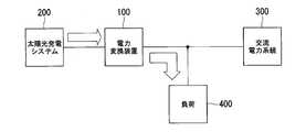
- FIG. 1 is a diagram illustrating an example of a configuration of a power conversion device 100 of the embodiment.
- a solar power generation system 200, an AC power system 300, and a load 400 are connected to the power conversion device 100.
- the solar power generation system 200 is realized by, for example, a solar panel or the like, and supplies the generated DC power to the power conversion device 100.
- the power conversion device 100 converts the DC power generated by the solar power generation system 200 into system power (that is, AC power) supplied by the AC power system 300 and supplies the system power or the load 400 to the AC power system 300.
- the system power is, for example, single-phase or three-phase AC power.
- the power converter 100 is, for example, a PCS (Power Conditioning Subsystem).
- the AC power system 300 supplies system power to the load 400 connected to the AC power system 300.
- the load 400 operates by the power converter 100 or the electric power supplied from the load 400.
- the power generation system connected to the power conversion device 100 is not limited to the solar power generation system 200, and may be a fuel cell, a gas engine, or the like.
- the solar power generation system 200 is an example of a “DC voltage source”.
- FIG. 1 shows the direction of current when the converted power is larger than the power consumption.
- the power obtained by subtracting the power consumption from the converted power is supplied to the AC power system 300. Therefore, the direction from the power conversion device 100 to the AC power system 300 and the direction from the power conversion device 100 to the load 400. Current flows in the direction of.
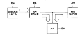
- FIG. 2 is a diagram illustrating an example of the direction of current when the converted power and the power consumption match. As shown in FIG.
- FIG. 3 is a diagram showing an example of the direction of current when power consumption is larger than converted power. As shown in FIG. 3, in this case, the converted power alone cannot cover the power consumption, and since the power is supplied from the AC power system 300 to the load 400, the direction from the power conversion device 100 to the load 400, and the AC power. A current flows from the system 300 toward the load 400.
- the power conversion device 100 compensates for the reduced system power. Since the converted power is output, an overcurrent may occur and the operation may stop.
- a plurality of power conversion devices 100 are connected (connected) to the AC power system 300, if the power conversion devices 100 are stopped all at once, the conversion power is not supplied to the load 400, and the AC power is not supplied.
- the grid power of the grid 300 may become unstable.
- the power conversion device 100 has a continuous operation performance (hereinafter, referred to as an FRT (Fault Ride Through) during a system disturbance such as a voltage drop of the AC power system 300 or a power failure (including an instantaneous power failure). )) Is required.
- FRT fault Ride Through
- system frequency the frequency of system power
- system voltage the voltage of system power
- conversion frequency the frequency of converted power
- conversion voltage the voltage of converted power
- FIG. 4 to 8 are diagrams showing examples of FRT requirements.
- FIG. 4 is a diagram showing an example of the FRT related to the voltage withstand capability.
- the power conversion device 100 is required to continue operation as a FRT when the system voltage drops, for a voltage drop in which the system voltage is 30 [%] or more of the normal time and the duration is 1 [second] or less.
- FIG. 5 is a diagram illustrating an example of an FRT related to restoration of system power.
- the power conversion device 100 as the FRT at the time of restoration of the system voltage, returns to the system voltage within 0.5 [seconds] after the system voltage is restored after the system voltage has dropped to 30% or more of the normal voltage. It is required to output 80% or more of the converted voltage output before the drop.
- FIG. 4 is a diagram showing an example of the FRT related to the voltage withstand capability.
- the power conversion device 100 is required to continue operation as a FRT when the system voltage drops, for a voltage drop in which the system voltage is 30 [%] or more
- FIG. 6 is a diagram showing another example of the FRT relating to the restoration of the system power. It is a figure which shows an example of FRT concerning the restoration of a system voltage.
- the power conversion device 100 returns to the normal state within 1.0 [second] after the restoration when the system voltage is reduced to a voltage lower than 30 [%] of the normal state and then restored. It is required to output 80% or more of the converted voltage of.
- FIG. 7 is a diagram showing an example of FRT related to system frequency fluctuation.
- the power conversion device 100 has a stepwise frequency variation of +0.8 [Hz] (in the AC power system 300 having a system frequency of 60 [Hz]). , +1.0 [Hz]), it is required to continue the operation for the frequency fluctuation that continues for 3 cycles.
- FIG. 8 is a diagram showing another example of the FRT related to the frequency fluctuation of system power.
- the power conversion device 100 is required to continue operation with respect to the frequency fluctuation of the system frequency of ⁇ 2 [Hz / s] in a ramp shape.
- the upper limit of the frequency fluctuation is 51.5 [Hz] in the case of the AC power system 300 having a system frequency of 50 [Hz], and 61.8 in the case of the AC power system 300 having a system frequency of 60 [Hz]. [Hz].
- the lower limit of the frequency fluctuation is 47.5 [Hz] in the case of the AC power system 300 having a system frequency of 50 [Hz], and 57.0 in the case of the AC power system 300 having a system frequency of 60 [Hz]. [Hz].
- the power conversion device 100 is required to have the above-described FRT, but is not disconnected during a system disturbance such as a system voltage drop or a system frequency change, and if the islanding operation is continued, there is essentially no power consumption during the system disturbance. Since the power is supplied to the range that should be, it may affect the safety of human body and equipment. Specifically, if the power converter 100 continues to operate independently, the electric shock of the public or accident removal workers may occur, the equipment may be damaged, fire fighting activities may be hindered, and accident point search may be hindered. It may happen.
- the power conversion device 100 of the present embodiment has the FRT according to the state of the AC power system 300, and suppresses the continuous operation of the power conversion device 100.
- FIG. 9 shows an example of the configuration of the power conversion device 100 according to this embodiment.
- the power conversion device 100 includes an inverter circuit 10, a circuit breaker 20, a transformer 30, a control unit 110, and a storage unit 120.
- the inverter circuit 10 includes one or more switching elements (not shown). DC power generated by the solar power generation system 200 is supplied to the inverter circuit 10. The open / closed state of the switching element of the inverter circuit 10 is controlled by the control unit 110. As a result, the control unit 110 uses the inverter circuit 10 to convert the DC power supplied from the photovoltaic power generation system 200 into system power (that is, AC power).
- the circuit breaker 20 is provided in the middle of a line connecting the inverter circuit 10 and the AC power system 300, one end of which is connected to the inverter circuit 10 and the other end of which is connected to the AC power system 300. Then, the circuit breaker 20 is controlled in the open / closed state based on the control of the control unit 110, disconnects the power conversion device 100 from the AC power system 300 in the open state, and opens the AC power system 300 in the closed state. Connect 100.
- the transformer 30 measures, for example, the instantaneous voltage of the power supplied to the installed line.
- the line on which the transformer 30 is installed is supplied with the converted power converted by the inverter circuit 10 when the circuit breaker 20 is in the open state, and when the circuit breaker 20 is in the closed state.
- the voltage detected by the transformer 30 is the converted voltage or the combined voltage of the converted power and the system voltage.
- the voltage detected by the transformer 30 is the converted voltage. Since the converted voltage is adjusted so as to be tuned to the system voltage, the combined voltage of the converted voltage and the system voltage matches the system voltage.
- the power conversion device 100 may include a number of transformers 30 corresponding to the number of phases of AC power (that is, three in this example), and measure the ground voltage of each phase, respectively.
- the ground voltage of the representative phase may be measured, and the ground voltage of each of the three phases may be measured by converting the measurement result into a phase.
- the transformer 30 is an example of a “voltage detector”.
- the control unit 110 for example, a processor such as a CPU (Central Processing Unit) executes a program (software) stored in the storage unit 120, so that the harmonic voltage calculation unit 111, the frequency detection unit 112, and the inverter control unit.
- the functional units of the unit 113, the frequency feedback control unit 114, the reactive power step injection unit 115, and the determination unit 116 are realized.
- Some or all of the components of the control unit 110 may be realized by hardware such as an LSI (Large Scale Integration), an ASIC (Application Specific Integrated Circuit), and an FPGA (Field-Programmable Gate Array).
- the storage unit 120 includes, for example, a non-volatile storage medium such as a ROM (Read Only Memory), a flash memory, a HDD (Hard Disk Drive), an SD card, an MRAM (Magnetoresistive Random Access Memory), a RAM (Random Access Memory), It may be realized by a volatile storage medium such as a register. Further, a part or all of the storage unit 120 may be an accessible external device of the power conversion device 100, such as a NAS (Network Attached Storage) or an external storage server.
- the storage unit 120 stores predetermined change degree information 121, predetermined voltage information 122, and predetermined harmonic voltage information 123. Details of various information will be described later.
- the harmonic voltage calculation unit 111 Fourier-transforms the voltage detected by the transformer 30 (system voltage, converted voltage, or combined voltage of system voltage and converted voltage) based on the instantaneous voltage measured by the transformer 30. , Calculate the harmonic voltage.
- the harmonic voltage calculation unit 111 calculates the harmonic voltage using, for example, the second to seventh harmonics or the discrete Fourier analysis of Expressions (1) to (3).
- the frequency detection unit 112 acquires the instantaneous voltage measured by the transformer 30 every predetermined time and detects the frequency based on the acquired voltage.
- the frequency detection unit 112 detects the frequency, for example, based on the timing (zero cross timing) at which the instantaneous voltage measured by the transformer 30 becomes 0 [V]. Therefore, the frequency detected by the frequency detection unit 112 is updated every cycle.
- the frequency detected by the frequency detection unit 112 is a combined frequency of the conversion frequency and the system frequency when the AC power system 300 has no system disturbance, and when the AC power system 300 has the disturbance (that is, , When the power conversion device 100 is operating independently), the conversion frequency is obtained.
- the conversion frequency is adjusted so as to tune to the system frequency, the combined frequency of the conversion frequency and the system frequency matches the system frequency.
- the inverter control unit 113 controls the operation of the inverter circuit 10 based on the processing result of each functional unit included in the control unit 110.
- the frequency feedback control unit 114 is an example of an active islanding detection method, and calculates the frequency deviation based on the frequency detected by the frequency detection unit 112.
- the frequency feedback control unit 114 calculates the moving average value of the frequencies detected between 200 [ms] before and 320 [ms] before the timing when the latest frequency is detected by the frequency detection unit 112 as the past frequency. Calculate as an average.
- the frequency feedback control unit 114 calculates a moving average value of frequencies detected up to 40 [ms] before the timing at which the latest frequency is detected as the latest frequency average. Then, the frequency feedback control unit 114 subtracts the latest frequency from the past frequency and calculates it as a frequency deviation.
- the inverter control unit 113 injects the injected reactive power amount into the converted power based on the frequency deviation calculated by the frequency feedback control unit 114.
- the frequency deviation calculated by the frequency feedback control unit 114 is ⁇ 4.0 [ ⁇ s in the AC power system 300 that supplies the system power of ⁇ 0.01 [Hz] (50 [Hz]). ], ⁇ 2.8 [ ⁇ s]) in the AC power system 300 that supplies the system power of 60 [Hz], ⁇ 0.25 [p. u. ] Reactive power is injected in the range.
- the timing at which the inverter control unit 113 injects reactive power is within a half cycle of the frequency detected by the frequency detection unit 112 from the timing at which the frequency deviation is ⁇ 0.01 [Hz].
- the inverter control unit 113 continuously performs the control (injection of reactive power) to advance the phase of the conversion frequency with respect to the system frequency, and the frequency deviation is negative.
- the control of delaying the phase of the conversion frequency with respect to the system frequency injection of reactive power
- the frequency feedback control unit 114 can prompt the frequency shift of the converted power.
- the frequency feedback control unit 114 continuously performs control to inject reactive power when the power conversion device 100 is in an isolated operation state, the frequency deviation between the system frequency and the conversion frequency is further expanded (frequency shift is promoted). Therefore, it is possible to make it easier for the determining unit 116 described later to determine that the power conversion device 100 is in the isolated operation state.
- the reactive power step injection unit 115 is an example of an active islanding detection method, and injects reactive power into the converted power stepwise so as to promote the frequency shift of the converted frequency.
- the reactive power step injection unit 115 can increase the frequency deviation of the conversion frequency by step-injecting the reactive power.
- the reactive power step injecting unit 115 detects the reactive power based on the frequency deviation calculated by the frequency feedback control unit 114, the harmonic voltage calculated by the harmonic voltage calculating unit 111, and the voltage detected by the transformer 30.
- the reactive power step injection unit 115 determines whether or not the power is stepwise injected. For example, when the frequency deviation calculated by the frequency feedback control unit 114 is ⁇ 0.01 [Hz] and all of the expressions (4) to (9) are satisfied, the reactive power step injection unit 115: Alternatively, when all of the expressions (10) to (15) are satisfied, it is determined that the reactive power is stepwise injected.
- Nhi 2nd to 7th harmonic voltage effective value before i cycles (i is a natural number)
- Nh_ave Three harmonic voltage average values from 3 cycles before to 5 cycles before
- Nb0-Nb_ave > 2.5 [V] ... (10) (Nb1-Nb_ave)> 2.5 [V] ... (11) (Nb2-Nb_ave)>-0.5 [V] ... (12) -0.5 [V] ⁇ (Nb3-Nb_ave) ⁇ 0.5 [V] ... (13) -0.5 [V] ⁇ (Nb4-Nb_ave) ⁇ 0.5 [V] ... (14) -0.5 [V] ⁇ (Nb5-Nb_ave) ⁇ 0.5 [V] ... (15) Nbi: fundamental wave voltage before i cycles Nb_ave: three fundamental wave voltage average values from 3 cycles before to 5 cycles before
- the inverter control unit 113 when the reactive power step injection unit 115 determines to step-inject the reactive power, injects the reactive power into the converted power stepwise.
- the injection time for stepwise injecting the reactive power is, for example, a time of 3 cycles or less of the frequency detected by the frequency detection unit 112.
- the reactive power injection upper limit is, for example, 0.1 [p. u. ].
- the inverter control unit 113 step-injects the reactive power in the direction of delaying the phase of the converted power based on the determination result of the reactive-power step injection unit 115.
- the timing at which the frequency feedback control unit 114 injects the reactive power stepwise is as follows when the reactive power step injection unit 115 has a frequency deviation of ⁇ 0.01 [Hz]. Is a timing within a half cycle of the system frequency after it is determined that all of the above are satisfied or all of the expressions (10) to (15) are satisfied.
- the reactive power step injection unit 115 can prompt the frequency shift of the converted power.
- the control for stepwise injecting the reactive power is performed when the power conversion device 100 is in the independent operation state, the frequency deviation between the system frequency and the conversion frequency is further expanded (frequency shift is promoted), and the power conversion device 100 is It can be easily determined by the determination unit 116, which will be described later, that the vehicle is in the isolated operation state.
- the control for injecting the reactive power by the frequency feedback control unit 114 or the reactive power step injection unit 115 is performed. Even if it is performed, since the entire AC power system 300 operates to reduce the reactive power, the frequency deviation between the system frequency and the conversion frequency is not expanded, and the power conversion device 100 is not in the independent operation.
- the determination unit 116 is an example of a passive islanding detection method, and performs power conversion based on the detection result of the frequency detection unit 112, the detection result of the harmonic voltage calculation unit 111, and the detection result of the transformer 30. It is determined whether the device 100 is in an isolated operation. The determination conditions of the determination unit 116 will be described below.
- the determination unit 116 determines whether or not the power conversion device 100 is operating independently based on the predetermined change degree information 121, the predetermined voltage information 122, the detection result of the transformer 30, and the detection result of the frequency detection unit 112. To determine.
- the determination unit 116 is a frequency detected by the frequency detection unit 112, and is a frequency at a certain timing (hereinafter, first timing) and a frequency detected at a timing after the first timing (hereinafter, second timing).
- the predetermined degree of change is, for example, a degree of change larger than the FRT requirement (that is, ⁇ 2 [Hz / sec] (see FIG. 8)).
- the determination unit 116 determines that the power conversion device 100 operates independently based on the predetermined change degree information 121, the predetermined harmonic voltage information 123, the detection result of the harmonic voltage calculation unit 111, and the detection result of the frequency detection unit 112. It is determined whether it is in the middle. The determination unit 116 determines that the degree of change detected by the frequency detection unit 112 is larger than the predetermined change degree indicated in the predetermined change degree information 121, and that the harmonic voltage calculated by the harmonic voltage calculation unit 111 is predetermined. When it is equal to or higher than the predetermined threshold value indicated by the harmonic voltage information 123, it is determined that the power conversion device 100 is in the isolated operation.
- the predetermined threshold value indicated by the predetermined harmonic voltage information 123 is, for example, the threshold value of the third-order harmonic voltage, and the determination unit 116 determines the third-order harmonic among the harmonic voltages calculated by the harmonic voltage calculation unit 111. Based on the value of the wave voltage and the predetermined threshold value indicated by the predetermined harmonic voltage information 123, it is determined whether or not the power conversion device 100 is operating independently. It should be noted that the predetermined harmonic voltage information 123 may store threshold values of higher or higher harmonic voltages. In this case, the determination unit 116 compares the threshold value of the third or higher harmonic voltage indicated in the predetermined harmonic voltage information 123 with the corresponding harmonic voltage calculated by the harmonic voltage calculation unit 111, respectively, and determines the power consumption. It may be determined whether the conversion device 100 is in an isolated operation.
- the determination unit 116 may perform the determination related to the islanding operation using only the determination condition 1 or only the determination condition 2, and based on both the conditions of the determination condition 1 and the determination condition 2, the determination unit 116 performs the independent operation. Such determination may be performed.
- the determination unit 116 determines that the power conversion device 100 is operating alone, it controls the inverter control unit 113 to stop the conversion operation of the inverter circuit 10. Then, the determination unit 116 controls the circuit breaker 20 to be in the open state and disconnects the power conversion device 100 from the AC power system 300.
- the determination unit 116 is an example of a “circuit breaker control unit”.
- the determination unit 116 may control the inverter control unit 113 to stop the conversion operation, or control the AC power system 300 to put it in the open state. .. When the determination unit 116 only stops the conversion operation, the power conversion device 100 does not have to include the circuit breaker 20.
- FIG. 10 is a flowchart showing an example of a series of flow of the determination process of the determination unit 116.
- the determination unit 116 uses the frequency detected by the frequency detection unit 112, and the change degree indicated by the difference between the frequency at the first timing and the frequency detected at the second timing is stored in the predetermined change degree information 121. It is determined whether or not the degree of change is larger than the predetermined degree shown (step S100). If the determination unit 116 determines that the degree of change is not greater than the predetermined degree of change, the process proceeds to step S110.
- step S102 the determination unit 116 determines that the degree of change is larger than the predetermined degree of change
- the voltage detected by the transformer 30 is lower than the predetermined voltage (system voltage in this example) indicated by the predetermined voltage information 122. It is determined whether it is low (step S102).
- the determination unit 116 determines that the voltage detected by the transformer 30 is not lower than the predetermined voltage, the process proceeds to step S110.
- the determination unit 116 determines whether the frequency detected by the frequency detection unit 112 is sufficiently different from the FRT requirement (step S104). Specifically, the determination unit 116 determines, based on the frequency detected by the frequency detection unit 112, that the change degree is a predetermined change degree based on the FRT requirement (for example, the AC power system 300 having a system frequency of 50 [Hz]). In the AC power system 300 with a system frequency of ⁇ 0.15 [Hz / sec] and a system frequency of 60 [Hz], a state of ⁇ 0.18 [Hz / sec] or more for a predetermined time (100 [in this example] msec]) or more is determined.
- step S110 If the determination unit 116 determines that the degree of change is not greater than or equal to the predetermined degree of change based on the FRT requirement, or that the state of the predetermined degree of change or greater has not continued for a predetermined period of time or more, the process proceeds to step S110.
- the frequency feedback control unit 114 calculates it. It is determined whether the frequency deviation is sufficiently different from the FRT requirement (step S106). Specifically, the determination unit 116 determines whether or not the frequency deviation calculated by the frequency feedback control unit 114 is equal to or greater than a predetermined threshold value (0.3 [Hz] in this example). If the determination unit 116 determines that the frequency deviation calculated by the frequency feedback control unit 114 is not greater than or equal to the predetermined threshold value, the process proceeds to step S110.
- a predetermined threshold value 0.3 [Hz] in this example
- the determination unit 116 determines that the frequency deviation is equal to or greater than the predetermined threshold value, the state of the power conversion device 100 is sufficiently different from the FRT requirement (that is, it is not desirable to continue the islanding operation). Yes), and the process proceeds to step S108.
- the determination unit 116 determines whether the harmonic voltage calculated by the harmonic voltage calculation unit 111 is equal to or higher than the predetermined threshold value indicated by the predetermined harmonic voltage information 123 (step S108). When the determination unit 116 determines that the harmonic voltage is not equal to or higher than the predetermined threshold value, the determination unit 116 determines that the power conversion device 100 is not operating alone (step S110). When the determination unit 116 determines that the harmonic voltage is equal to or higher than the predetermined threshold value, the determination unit 116 determines that the power conversion device 100 is in the independent operation (step S112).
- the determination unit 116 determines that the power conversion device 100 is in the independent operation, it controls the inverter control unit 113, causes the inverter circuit 10 to stop the conversion operation, and controls the circuit breaker 20 to be in the open state. Then, the power conversion device 100 is disconnected from the AC power system 300 (step S114).
- the processing of steps S104 and S106 may not be executed.
- the determination unit 116 advances the process to the determination process of step S108 after the determination process of step S102.
- the determination unit 116 determines that the change degree of the frequency detected by the frequency detection unit 112 is based on the detection result of the frequency detection unit 112 and the detection result of the transformer 30. , If the voltage detected by the transformer 30 is lower than the predetermined voltage, the power conversion device 100 is determined to be operating independently.
- the islanding operation of the power conversion device 100 is detected based on the detection result of detecting the voltage or current flowing into the load 400 or the current or voltage of the AC power system 300. However, in this case, depending on the detection accuracy of the detector, it may be erroneously detected that the power conversion device 100 is operating alone.
- the power converter 100 is unnecessarily disconnected from the AC power system 300 by detecting the state of the AC power system 300 more accurately according to various determination conditions. By suppressing the fact that the islanding operation of the power conversion device 100 is continued for a long time, it is possible to suppress a change in the power system.
Landscapes
- Engineering & Computer Science (AREA)
- Power Engineering (AREA)
- Supply And Distribution Of Alternating Current (AREA)
- Inverter Devices (AREA)
Abstract
実施形態の電力変換装置は、直流電圧源、及び交流電力系統に接続される電力変換装置であって、インバータ回路と、制御部と、周波数検出部と、電圧検出部と、判定部とを持つ。制御部は、インバータ回路のスイッチング素子を制御し、前記インバータ回路に、前記直流電圧源から供給される直流電力を前記交流電力系統に対応した交流電力に変換させる。周波数検出部は、前記交流電力系統の周波数を検出する。電圧検出部は、前記交流電力系統の電圧を検出する。判定部は、前記周波数検出部の検出結果と、前記電圧検出部の検出結果とに基づいて、自装置が単独運転中であるか否かを判定するものであって、前記周波数検出部によって検出された前記交流電力系統の周波数の変化程度が、所定の変化程度よりも大きく、且つ前記電圧検出部によって検出された前記交流電力系統の電圧が所定電圧よりも低い場合、自装置が単独運転中であると判定する。
Description
本発明の実施形態は、電力変換装置に関する。
近年、太陽電池、燃料電池、ガスエンジン等の発電電力を電力系統の電力系統に変換する電力変換装置が知られている。ここで、電力変換装置は、電力系統の瞬時電圧低下にともなって出力に過電流が発生し、動作が停止する場合がある。例えば、電力変換装置が電力系統に多数連系される場合において、各電力変換装置が一斉に停止してしまうと、負荷に供給される電力のバランスが崩れ、電力系統が不安定になってしまう恐れがある。これを抑制するため、従来、電力変換装置が、系統電圧に基づいて電力系統の瞬時電圧低下を検出し、出力する電力を一時的に停止しつつ、運転を継続することにより、電力系統の変化を抑制する技術が知られている。しかしながら、従来の技術では、系統の電圧及び周波数に基づいて瞬時電圧低下を検出するため、必要以上に出力を低下させてしてしまう場合があった。
本発明は、電力系統の変化を抑制することができる電力変換装置を提供することを目的とする。
本発明が解決しようとする課題は、電力系統の変化を抑制することができる、電力変換装置を提供することである。
実施形態の電力変換装置は、直流電圧源、及び交流電力系統に接続される電力変換装置であって、インバータ回路と、制御部と、周波数検出部と、電圧検出部と、判定部とを持つ。インバータ回路は、一以上のスイッチング素子を含む。制御部は、前記スイッチング素子を制御し、前記インバータ回路に、前記直流電圧源から供給される直流電力を前記交流電力系統に対応した交流電力に変換させる。周波数検出部は、前記交流電力系統の周波数を検出する。電圧検出部は、前記交流電力系統の電圧を検出する。判定部は、前記周波数検出部の検出結果と、前記電圧検出部の検出結果とに基づいて、自装置が単独運転中であるか否かを判定するものであって、前記周波数検出部によって検出された前記交流電力系統の周波数の変化程度が、所定の変化程度よりも大きく、且つ前記電圧検出部によって検出された前記交流電力系統の電圧が所定電圧よりも低い場合、自装置が単独運転中であると判定する。
以下、実施形態の電力変換装置を、図面を参照して説明する。
(実施形態)
[電力変換装置100の構成]
図1は、実施形態の電力変換装置100の構成の一例を示す図である。電力変換装置100には、太陽光発電システム200と、交流電力系統300と、負荷400とが接続される。太陽光発電システム200は、例えば、太陽光パネル等によって実現され、発電した直流電力を電力変換装置100に供給する。電力変換装置100は、太陽光発電システム200が発電した直流電力を交流電力系統300が供給する系統電力(つまり、交流電力)に変換し、交流電力系統300、又は負荷400に供給する。系統電力は、例えば、単相または、三相の交流電力である。電力変換装置100は、例えば、PCS(Power Conditioning Subsystem)である。交流電力系統300は、交流電力系統300に接続される負荷400に系統電力を供給する。負荷400は、電力変換装置100、又は負荷400から供給された電力によって動作する。
[電力変換装置100の構成]
図1は、実施形態の電力変換装置100の構成の一例を示す図である。電力変換装置100には、太陽光発電システム200と、交流電力系統300と、負荷400とが接続される。太陽光発電システム200は、例えば、太陽光パネル等によって実現され、発電した直流電力を電力変換装置100に供給する。電力変換装置100は、太陽光発電システム200が発電した直流電力を交流電力系統300が供給する系統電力(つまり、交流電力)に変換し、交流電力系統300、又は負荷400に供給する。系統電力は、例えば、単相または、三相の交流電力である。電力変換装置100は、例えば、PCS(Power Conditioning Subsystem)である。交流電力系統300は、交流電力系統300に接続される負荷400に系統電力を供給する。負荷400は、電力変換装置100、又は負荷400から供給された電力によって動作する。
なお、電力変換装置100に接続される発電システムは、太陽光発電システム200に限られず、燃料電池、ガスエンジン等であってもよい。太陽光発電システム200は、「直流電圧源」の一例である。
ここで、電力変換装置100が変換する電力(以下、変換電力)、及び負荷400が消費する電力(以下、消費電力)の大小関係によって、電力変換装置100、交流電力系統300、及び負荷400間を流れる電流の方向がそれぞれ異なる。図1には、変換電力が、消費電力よりも大きい場合の電流の方向が示される。図1に示す通り、この場合、変換電力から消費電力を差し引いた電力が、交流電力系統300に供給されるため、電力変換装置100から交流電力系統300の方向、及び電力変換装置100から負荷400の方向に電流が流れる。図2は、変換電力と、消費電力とが、一致する場合の電流の方向の一例を示す図である。図2に示す通り、この場合、変換電力から消費電力を差し引いた電力がゼロ(或いは、ほぼゼロ)になるため、交流電力系統300に電力が供給されず、電力変換装置100から負荷400の方向のみに電流が流れる。図3は、変換電力よりも消費電力が大きい場合の電流の方向の一例を示す図である。図3に示す通り、この場合、変換電力だけでは消費電力を賄うことができず、交流電力系統300から負荷400に電力が供給されるため、電力変換装置100から負荷400の方向、及び交流電力系統300から負荷400の方向に電流が流れる。
ここで、変換電力が消費電力よりも大きい場合、又は変換電力よりも消費電力が大きい場合に、交流電力系統300の系統電力が低下すると、電力変換装置100は、低下した系統電力を補うように変換電力を出力するため、過電流が発生し、動作が停止する場合がある。また、交流電力系統300に複数の電力変換装置100が接続(連系)されている場合において、電力変換装置100が一斉に停止してしまうと、負荷400に変換電力が供給されなくなり、交流電力系統300の系統電力が不安定になってしまう恐れがある。このような状態になることを抑制するため、電力変換装置100は、交流電力系統300の電圧低下や停電(瞬時停電を含む)等の系統擾乱時における運転継続性能(以下、FRT(Fault Ride Through))を有することが求められる。
以下、系統電力の周波数を「系統周波数」と記載し、系統電力の電圧を「系統電圧」と記載し、変換電力の周波数を「変換周波数」と記載し、変換電力の電圧を「変換電圧」と記載するものとする。
図4~図8は、FRT要件の一例を示す図である。図4は、電圧低下耐量に係るFRTの一例を示す図である。電力変換装置100は、系統電圧低下時におけるFRTとして、系統電圧が通常時の30[%]以上の継続時間が1[秒]以下である電圧低下に対しては運転継続することが求められる。図5は、系統電力の復帰に係るFRTの一例を示す図である。電力変換装置100は、系統電圧の復帰時におけるFRTとして、系統電圧が通常時の30[%]以上の電圧に低下してから復帰した場合、復帰から0.5[秒]以内に、系統電圧低下前に出力していた変換電圧の80[%]以上を出力することが求められる。図6は、系統電力の復帰に係るFRTの他の例を示す図である。系統電圧の復帰時に係るFRTの一例を示す図である。電力変換装置100は、系統電圧の復帰時におけるFRTとして、系統電圧が通常時の30[%]未満の電圧に低下してから復帰した場合、復帰から1.0[秒]以内に、通常時の変換電圧の80[%]以上を出力することが求められる。
図7は、系統周波数変動に係るFRTの一例を示す図である。電力変換装置100は、系統周波数が50[Hz]の交流電力系統300において、系統周波数の周波数変動がステップ状に+0.8[Hz](系統周波数が60[Hz]の交流電力系統300においては、+1.0[Hz])となる状態が、3サイクル間継続する周波数変動に対しては、運転を継続することが求められる。
図8は、系統電力の周波数変動に係るFRTの他の例を示す図である。電力変換装置100は、系統周波数の周波数変動がランプ状に±2[Hz/s]である周波数変動に対して、運転を継続することが求められる。ただし、周波数変動の上限は、系統周波数が50[Hz]の交流電力系統300の場合、51.5[Hz]であり、系統周波数が60[Hz]の交流電力系統300の場合、61.8[Hz]である。また、周波数変動の下限は、系統周波数が50[Hz]の交流電力系統300の場合、47.5[Hz]であり、系統周波数が60[Hz]の交流電力系統300の場合、57.0[Hz]である。
電力変換装置100は、上述したFRTを有することが求められる一方で、系統電圧低下や系統周波数変動等の系統擾乱時に解列されず、単独運転を継続し続けると、本来、系統擾乱時に無電力であるべき範囲に電力が供給されるため、人身、及び設備の安全に対して影響する場合がある。具体的には、電力変換装置100が単独運転を継続すると、公衆又は事故除去作業員の感電が発生したり、機器が損傷したり、消防活動の妨害になったり、事故点探査の妨害になったりする場合がある。本実施形態の電力変換装置100は、交流電力系統300の状態に応じて、FRTを有しつつ、電力変換装置100の単独運転が継続することを抑制する。
図9は、本実施形態に係る電力変換装置100の構成の一例を示す。電力変換装置100は、インバータ回路10と、遮断器20と、変圧器30と、制御部110と、記憶部120とを備える。インバータ回路10は、一以上のスイッチング素子(不図示)を備える。インバータ回路10には、太陽光発電システム200によって発電された直流電力が供給される。インバータ回路10のスイッチング素子の開閉状態は、制御部110により制御される。これにより、制御部110は、インバータ回路10を用いて、太陽光発電システム200から供給される直流電力を、系統電力(つまり、交流電力)に変換する。
遮断器20は、インバータ回路10と、交流電力系統300とを接続する線路の途中に設けられ、一端がインバータ回路10に接続され、他の一端が交流電力系統300に接続される。そして、遮断器20は、制御部110の制御に基づいて、開閉状態が制御され、開状態において交流電力系統300から電力変換装置100を解列し、閉状態において交流電力系統300に電力変換装置100を連系する。
変圧器30は、例えば、設置される線路に供給される電力の瞬時電圧を測定する。ここで、変圧器30が設置される線路には、遮断器20が開状態の場合、インバータ回路10によって変換された変換電力が供給され、遮断器20が閉状態の場合、変換電力と消費電力との大小関係によって、変換電力のみ、又は変換電力と系統電力とが供給される。したがって、遮断器20が閉状態であり、交流電力系統300に系統擾乱が生じていない場合、変圧器30が検出する電圧は、変換電圧、又は変換電力と系統電圧との合成電圧であるが、交流電力系統300に系統擾乱が生じている場合、変圧器30が検出する電圧は、変換電圧である。変換電圧は、系統電圧に同調するように調整されるため、変換電圧と系統電圧との合成電圧は、系統電圧と合致する。
なお、電力変換装置100は、変圧器30を交流電力の相数に応じた数(つまり、この一例では、三つ)備え、各相の対地電圧をそれぞれ測定してもよく、三相交流の代表相の対地電圧を測定し、測定結果を相変換することによって三相各相の対地電圧を測定してもよい。変圧器30は、「電圧検出部」の一例である。
制御部110は、例えば、CPU(Central Processing Unit)などのプロセッサが記憶部120に記憶されたプログラム(ソフトウェア)を実行することにより、高調波電圧算出部111と、周波数検出部112と、インバータ制御部113と、周波数フィードバック制御部114と、無効電力ステップ注入部115と、判定部116との各機能部を実現する。制御部110の構成要素の一部または全部は、LSI(Large ScaleIntegration)やASIC(Application Specific Integrated Circuit)、FPGA(Field-Programmable Gate Array)等のハードウェアによって実現されてもよい。
記憶部120は、例えば、ROM(Read Only Memory)、フラッシュメモリ、HDD(Hard Disk Drive)、SDカード、MRAM(Magnetoresistive Random Access Memory)等の不揮発性の記憶媒体と、RAM(Random Access Memory)、レジスタ等の揮発性の記憶媒体とによって実現されてよい。また、記憶部120の一部又は全部は、NAS(Network Attached Storage)や外部のストレージサーバ等、電力変換装置100のアクセス可能な外部装置であってもよい。記憶部120には、所定変化程度情報121と、所定電圧情報122と、所定高調波電圧情報123とが記憶される。各種情報の詳細については、後述する。
高調波電圧算出部111は、変圧器30によって測定された瞬時電圧に基づいて、変圧器30が検出する電圧(系統電圧、変換電圧、又は系統電圧と変換電圧との合成電圧)をフーリエ変換し、高調波電圧を算出する。高調波電圧算出部111は、例えば、2次~7次の高調波、又は式(1)~式(3)の離散フーリエ解析を用いて高調波電圧を算出する。

周波数検出部112は、変圧器30によって測定された瞬時電圧を所定の時間毎に取得し、取得した電圧に基づいて周波数を検出する。周波数検出部112は、例えば、変圧器30によって測定された瞬時電圧が0[V]となるタイミング(ゼロクロスタイミング)に基づいて、周波数を検出する。したがって、周波数検出部112によって検出される周波数は、1周期毎に更新される。ここで、周波数検出部112が検出する周波数は、交流電力系統300に系統擾乱が生じていない場合、変換周波数と系統周波数との合成周波数となり、交流電力系統300に擾乱が生じている場合(つまり、電力変換装置100が単独運転している場合)、変換周波数となる。ここで、変換周波数は、系統周波数に同調するように調整されるため、変換周波数と系統周波数との合成周波数は、系統周波数と合致する。
インバータ制御部113は、制御部110が備える各機能部の処理結果に基づいて、インバータ回路10の動作を制御する。
周波数フィードバック制御部114は、能動的な単独運転検出方式の一例であり、周波数検出部112によって検出された周波数に基づいて、周波数偏差を算出する。周波数フィードバック制御部114は、例えば、周波数検出部112によって最新の周波数が検出されたタイミングの200[ms]前から更に320[ms]前までの間に検出された周波数の移動平均値を過去周波数平均として算出する。周波数フィードバック制御部114は、最新の周波数が検出されたタイミングから40[ms]前までの間に検出された周波数の移動平均値を最近周波数平均として算出する。そして、周波数フィードバック制御部114は、過去周波数から最近周波数を差し引き、周波数偏差として算出する。
インバータ制御部113は、周波数フィードバック制御部114によって算出された周波数偏差に基づいて、変換電力に注入無効電力量を注入する。インバータ制御部113は、例えば、周波数フィードバック制御部114によって算出された周波数偏差が、±0.01[Hz](50[Hz]の系統電力を供給する交流電力系統300において±4.0[μs]、60[Hz]の系統電力を供給する交流電力系統300において±2.8[μs])となった場合、±0.25[p.u.]の範囲で無効電力を注入する。インバータ制御部113が無効電力を注入するタイミングは、周波数偏差が±0.01[Hz]となったタイミングから、周波数検出部112によって検出された周波数の半サイクル以内のタイミングである。
インバータ制御部113は、周波数フィードバック制御部114によって算出された周波数偏差が正の場合、系統周波数に対して変換周波数の位相を進める制御(無効電力の注入)を連続的に行い、周波数偏差が負の場合、系統周波数に対して変換周波数の位相を遅らせる制御(無効電力の注入)を連続的に行う。これにより、周波数フィードバック制御部114は、変換電力の周波数シフトを促すことができる。電力変換装置100が単独運転状態である場合に、周波数フィードバック制御部114が無効電力を注入する制御を連続的に行うと、系統周波数と変換周波数との周波数偏差が更に拡大され(周波数シフトが促され)、電力変換装置100が単独運転状態であることを、後述する判定部116によって判定しやすくすることができる。
無効電力ステップ注入部115は、能動的な単独運転検出方式の一例であり、変換周波数の周波数シフトを助長させるように変換電力に無効電力をステップ注入する。ここで、変換電力と、消費電力とが一致(平衡)する場合において、交流電力系統300に系統擾乱が生じても、変換周波数に周波数偏差が生じない場合がある。このような場合、電力変換装置100の単独運転が継続されてしまう恐れがある。無効電力ステップ注入部115は、このような場面において、無効電力をステップ注入することにより、変換周波数の周波数偏差を拡大させることができる。無効電力ステップ注入部115は、周波数フィードバック制御部114によって算出された周波数偏差と、高調波電圧算出部111によって算出された高調波電圧と、変圧器30によって検出された電圧とに基づいて、無効電力をステップ注入するか否かを判定する。無効電力ステップ注入部115は、例えば、周波数フィードバック制御部114によって算出された周波数偏差が、±0.01[Hz]となった場合において、式(4)~(9)の全てが成り立つ場合、又は式(10)~(15)の全てが成り立つ場合に、無効電力をステップ注入すると判定する。
(Nh0-Nh_ave)>2[V]…(4)
(Nh1-Nh_ave)>[V]…(5)
(Nh2-Nh_ave)>-0.5[V]…(6)
-0.5[V]<(Nh3-Nh_ave)<0.5[V]…(7)
-0.5[V]<(Nh4-Nh_ave)<0.5[V]…(8)
-0.5[V]<(Nh5-Nh_ave)<0.5[V]…(9)
Nhi:iサイクル(iは、自然数)前の2次~7次の高調波電圧実効値
Nh_ave:3サイクル前から5サイクル前までの3個の高調波電圧平均値
(Nh1-Nh_ave)>[V]…(5)
(Nh2-Nh_ave)>-0.5[V]…(6)
-0.5[V]<(Nh3-Nh_ave)<0.5[V]…(7)
-0.5[V]<(Nh4-Nh_ave)<0.5[V]…(8)
-0.5[V]<(Nh5-Nh_ave)<0.5[V]…(9)
Nhi:iサイクル(iは、自然数)前の2次~7次の高調波電圧実効値
Nh_ave:3サイクル前から5サイクル前までの3個の高調波電圧平均値
(Nb0-Nb_ave)>2.5[V]…(10)
(Nb1-Nb_ave)>2.5[V]…(11)
(Nb2-Nb_ave)>-0.5[V]…(12)
-0.5[V]<(Nb3-Nb_ave)<0.5[V]…(13)
-0.5[V]<(Nb4-Nb_ave)<0.5[V]…(14)
-0.5[V]<(Nb5-Nb_ave)<0.5[V]…(15)
Nbi:iサイクル前の基本波電圧
Nb_ave:3サイクル前から5サイクル前までの3個の基本波電圧平均値
(Nb1-Nb_ave)>2.5[V]…(11)
(Nb2-Nb_ave)>-0.5[V]…(12)
-0.5[V]<(Nb3-Nb_ave)<0.5[V]…(13)
-0.5[V]<(Nb4-Nb_ave)<0.5[V]…(14)
-0.5[V]<(Nb5-Nb_ave)<0.5[V]…(15)
Nbi:iサイクル前の基本波電圧
Nb_ave:3サイクル前から5サイクル前までの3個の基本波電圧平均値
インバータ制御部113は、無効電力ステップ注入部115が無効電力をステップ注入すると判定した場合、変換電力に無効電力をステップ注入する。無効電力をステップ注入する注入時間は、例えば、周波数検出部112によって検出された周波数の3サイクル以下の時間である。無効電力の注入上限は、例えば、0.1[p.u.]である。インバータ制御部113は、無効電力ステップ注入部115の判定結果に基づいて、変換電力の位相を遅らせる方向に無効電力をステップ注入する。周波数フィードバック制御部114が無効電力をステップ注入するタイミングは、無効電力ステップ注入部115が、周波数偏差が、±0.01[Hz]となった場合において、上述した式(4)~(9)の全てが成り立つ、又は式(10)~(15)の全てが成り立つと判定してから、系統周波数の半サイクル以内のタイミングである。
これにより、無効電力ステップ注入部115は、変換電力の周波数シフトを促すことができる。電力変換装置100が単独運転状態である場合に、無効電力をステップ注入する制御を行うと、系統周波数と変換周波数との周波数偏差が更に拡大され(周波数シフトが促され)、電力変換装置100が単独運転状態であることを、後述する判定部116によって判定しやすくすることができる。
なお、電力変換装置100が単独運転状態ではない(つまり、交流電力系統300に系統擾乱が生じていない)場合に、周波数フィードバック制御部114や無効電力ステップ注入部115によって無効電力を注入する制御が行われても、交流電力系統300全体が無効電力を減少させるように動作するため、系統周波数と変換周波数との周波数偏差が拡大されず、電力変換装置100が単独運転ではないこととなる。
判定部116は、受動的な単独運転検出方式の一例であり、周波数検出部112の検出結果と、高調波電圧算出部111の検出結果と、変圧器30の検出結果とに基づいて、電力変換装置100が単独運転中であるか否かを判定する。以下、判定部116の判定条件について説明する。
<判定条件1:周波数の変化程度と、電圧に基づく判定>
判定部116は、所定変化程度情報121と、所定電圧情報122と、変圧器30の検出結果と、周波数検出部112の検出結果とに基づいて、電力変換装置100が単独運転中であるか否かを判定する。判定部116は、周波数検出部112によって検出された周波数であり、あるタイミング(以下、第1タイミング)における周波数と、第1タイミングよりも後のタイミング(以下、第2タイミング)において検出された周波数との差分によって示される変化程度が、所定変化程度情報121に示される所定の変化程度よりも大きく、且つ変圧器30によって検出された電圧が、所定電圧情報122に示される所定電圧よりも低い場合、電力変換装置100が単独運転中であると判定する。所定の変化程度は、例えば、FRT要件(つまり、±2[Hz/sec](図8参照))よりも大きい変化程度である。
判定部116は、所定変化程度情報121と、所定電圧情報122と、変圧器30の検出結果と、周波数検出部112の検出結果とに基づいて、電力変換装置100が単独運転中であるか否かを判定する。判定部116は、周波数検出部112によって検出された周波数であり、あるタイミング(以下、第1タイミング)における周波数と、第1タイミングよりも後のタイミング(以下、第2タイミング)において検出された周波数との差分によって示される変化程度が、所定変化程度情報121に示される所定の変化程度よりも大きく、且つ変圧器30によって検出された電圧が、所定電圧情報122に示される所定電圧よりも低い場合、電力変換装置100が単独運転中であると判定する。所定の変化程度は、例えば、FRT要件(つまり、±2[Hz/sec](図8参照))よりも大きい変化程度である。
<判定条件2:周波数の変化程度と、高調波電圧に基づく判定>
判定部116は、所定変化程度情報121と、所定高調波電圧情報123と、高調波電圧算出部111の検出結果と、周波数検出部112の検出結果とに基づいて、電力変換装置100が単独運転中であるか否かを判定する。判定部116は、周波数検出部112によって検出された変化程度が、所定変化程度情報121に示される所定の変化程度よりも大きく、且つ高調波電圧算出部111によって算出された高調波電圧が、所定高調波電圧情報123によって示される所定の閾値以上である場合、電力変換装置100が単独運転中であると判定する。所定高調波電圧情報123によって示される所定の閾値は、例えば、3次高調波電圧の閾値であり、判定部116は、高調波電圧算出部111によって算出された高調波電圧のうち、3次高調波電圧の値と、所定高調波電圧情報123が示す所定の閾値とに基づいて、電力変換装置100が単独運転中であるか否かを判定する。なお、所定高調波電圧情報123には、3次以上の高調波電圧の閾値が記憶されてもよい。この場合、判定部116は、所定高調波電圧情報123に示される3次以上の高調波電圧の閾値と、高調波電圧算出部111によって算出された対応する高調波電圧とをそれぞれ比較し、電力変換装置100が単独運転中であるか否かを判定してもよい。
判定部116は、所定変化程度情報121と、所定高調波電圧情報123と、高調波電圧算出部111の検出結果と、周波数検出部112の検出結果とに基づいて、電力変換装置100が単独運転中であるか否かを判定する。判定部116は、周波数検出部112によって検出された変化程度が、所定変化程度情報121に示される所定の変化程度よりも大きく、且つ高調波電圧算出部111によって算出された高調波電圧が、所定高調波電圧情報123によって示される所定の閾値以上である場合、電力変換装置100が単独運転中であると判定する。所定高調波電圧情報123によって示される所定の閾値は、例えば、3次高調波電圧の閾値であり、判定部116は、高調波電圧算出部111によって算出された高調波電圧のうち、3次高調波電圧の値と、所定高調波電圧情報123が示す所定の閾値とに基づいて、電力変換装置100が単独運転中であるか否かを判定する。なお、所定高調波電圧情報123には、3次以上の高調波電圧の閾値が記憶されてもよい。この場合、判定部116は、所定高調波電圧情報123に示される3次以上の高調波電圧の閾値と、高調波電圧算出部111によって算出された対応する高調波電圧とをそれぞれ比較し、電力変換装置100が単独運転中であるか否かを判定してもよい。
なお、判定部116は、判定条件1のみ、又は判定条件2のみを用いて単独運転に係る判定を行ってもよく、判定条件1、及び判定条件2の両方の条件に基づいて、単独運転に係る判定を行ってもよい。
判定部116は、電力変換装置100が単独運転していると判定した場合、インバータ制御部113を制御し、インバータ回路10の変換動作を停止させる。そして、判定部116は、遮断器20を開状態に制御し、電力変換装置100を交流電力系統300から解列させる。判定部116は、「遮断器制御部」の一例である。
なお、判定部116は、インバータ制御部113を制御し、変換動作を停止させること、又は交流電力系統300を制御し、開状態にすることのうち、いずれか一方を行うものであってもよい。判定部116が、変換動作の停止のみを行う場合には、電力変換装置100は、遮断器20を備えていなくてもよい。
[動作フロー]
図10は、判定部116の判定処理の一連の流れの一例を示すフローチャートである。まず、判定部116は、周波数検出部112によって検出された周波数であり、第1タイミングにおける周波数と、第2タイミングにおいて検出された周波数との差分によって示される変化程度が、所定変化程度情報121に示される所定の変化程度よりも大きいか否かを判定する(ステップS100)。判定部116は、変化程度が、所定の変化程度よりも大きくないと判定した場合、処理をステップS110に進める。判定部116は、変化程度が、所定の変化程度よりも大きいと判定した場合、変圧器30によって検出された電圧が、所定電圧情報122に示される所定電圧(この一例では、系統電圧)よりも低いか否かを判定する(ステップS102)。判定部116は、変圧器30によって検出された電圧が、所定電圧よりも低くないと判定した場合、処理をステップS110に進める。
図10は、判定部116の判定処理の一連の流れの一例を示すフローチャートである。まず、判定部116は、周波数検出部112によって検出された周波数であり、第1タイミングにおける周波数と、第2タイミングにおいて検出された周波数との差分によって示される変化程度が、所定変化程度情報121に示される所定の変化程度よりも大きいか否かを判定する(ステップS100)。判定部116は、変化程度が、所定の変化程度よりも大きくないと判定した場合、処理をステップS110に進める。判定部116は、変化程度が、所定の変化程度よりも大きいと判定した場合、変圧器30によって検出された電圧が、所定電圧情報122に示される所定電圧(この一例では、系統電圧)よりも低いか否かを判定する(ステップS102)。判定部116は、変圧器30によって検出された電圧が、所定電圧よりも低くないと判定した場合、処理をステップS110に進める。
次に、判定部116は、周波数検出部112によって検出された周波数が、FRT要件と十分に異なっているかを判定する(ステップS104)。具体的には、判定部116は、周波数検出部112によって検出された周波数に基づいて、変化程度が、FRT要件に基づく所定の変化程度(例えば、系統周波数が50[Hz]の交流電力系統300において、±0.15[Hz/sec]、系統周波数が60[Hz]の交流電力系統300において、±0.18[Hz/sec])以上の状態が、所定時間(この一例では、100[msec])以上継続しているか否かを判定する。判定部116は、変化程度が、FRT要件に基づく所定の変化程度以上ではない、又は所定の変化程度以上の状態が所定時間以上継続していないと判定した場合、処理をステップS110に進める。
判定部116は、変化程度が、FRT要件に基づく所定の変化程度以上ではない、又は所定の変化程度以上の状態が所定時間以上継続していると判定した場合、周波数フィードバック制御部114によって算出された周波数偏差が、FRT要件と十分に異なっているかを判定する(ステップS106)。具体的には、判定部116は、周波数フィードバック制御部114によって算出された周波数偏差が、所定の閾値(この一例では、0.3[Hz])以上であるか否かを判定する。判定部116は、周波数フィードバック制御部114によって算出された周波数偏差が、所定の閾値以上ではないと判定した場合、処理をステップS110に進める。判定部116は、周波数偏差が、所定の閾値以上であると判定した場合、電力変換装置100の状態が、FRT要件と十分に異なっている(つまり、単独運転を継続することが好ましくない状態である)と判定し、処理をステップS108に進める。
次に、判定部116は、高調波電圧算出部111によって算出された高調波電圧が、所定高調波電圧情報123によって示される所定の閾値以上であるか否かを判定する(ステップS108)。判定部116は、高調波電圧が、所定の閾値以上ではないと判定した場合、電力変換装置100が単独運転中ではないと判定する(ステップS110)。判定部116は、高調波電圧が、所定の閾値以上であると判定した場合、電力変換装置100が単独運転中であると判定する(ステップS112)。次に、判定部116は、電力変換装置100が単独運転中であると判定した場合、インバータ制御部113を制御し、インバータ回路10に変換動作を停止させ、且つ遮断器20を開状態に制御し、交流電力系統300から電力変換装置100を解列させる(ステップS114)。
なお、既に電力変換装置100がFRT要件に基づく動作以上の動作を行っていることが予め明らかである場合、ステップS104と、ステップS106との処理は、実行されなくてもよい。この場合、判定部116は、ステップS102の判定処理の後、ステップS108の判定処理に処理を進める。
[実施形態のまとめ]
以上説明したように、電力変換装置100において、判定部116は、周波数検出部112の検出結果と、変圧器30の検出結果とに基づいて、周波数検出部112によって検出された周波数の変化程度が、所定の変化程度よりも大きく、且つ変圧器30によって検出された電圧が所定電圧よりも低い場合、電力変換装置100が単独運転中であると判定する。ここで、従来の技術では、負荷400に流入する電圧や電流を検出したり、交流電力系統300の電流や電圧を検出したりした検出結果に基づいて、電力変換装置100の単独運転を検出していたが、この場合、検出器の検出精度によっては、電力変換装置100が単独運転していると誤検出される場合があった。本実施形態の電力変換装置100によれば、種々の判定条件によって交流電力系統300の状態をより精度良く検出することにより、不必要に電力変換装置100が交流電力系統300から解列されたり、電力変換装置100の単独運転が長時間継続されたりすることを抑制することにより、電力系統の変化を抑制することができる。
以上説明したように、電力変換装置100において、判定部116は、周波数検出部112の検出結果と、変圧器30の検出結果とに基づいて、周波数検出部112によって検出された周波数の変化程度が、所定の変化程度よりも大きく、且つ変圧器30によって検出された電圧が所定電圧よりも低い場合、電力変換装置100が単独運転中であると判定する。ここで、従来の技術では、負荷400に流入する電圧や電流を検出したり、交流電力系統300の電流や電圧を検出したりした検出結果に基づいて、電力変換装置100の単独運転を検出していたが、この場合、検出器の検出精度によっては、電力変換装置100が単独運転していると誤検出される場合があった。本実施形態の電力変換装置100によれば、種々の判定条件によって交流電力系統300の状態をより精度良く検出することにより、不必要に電力変換装置100が交流電力系統300から解列されたり、電力変換装置100の単独運転が長時間継続されたりすることを抑制することにより、電力系統の変化を抑制することができる。
本発明のいくつかの実施形態を説明したが、これらの実施形態は、例として提示したものであり、発明の範囲を限定することは意図していない。これら実施形態は、その他の様々な形態で実施されることが可能であり、発明の要旨を逸脱しない範囲で、種々の省略、置き換え、変更を行うことができる。これら実施形態やその変形は、発明の範囲や要旨に含まれると同様に、特許請求の範囲に記載された発明とその均等の範囲に含まれるものである。
Claims (7)
- 直流電圧源、及び交流電力系統に接続される電力変換装置であって、
一以上のスイッチング素子を含むインバータ回路と、
前記スイッチング素子を制御し、前記インバータ回路に、前記直流電圧源から供給される直流電力を前記交流電力系統に対応した交流電力に変換させる制御部と、
前記交流電力系統の周波数を検出する周波数検出部と、
前記交流電力系統の電圧を検出する電圧検出部と、
前記周波数検出部の検出結果と、前記電圧検出部の検出結果とに基づいて、自装置が単独運転中であるか否かを判定する判定部とを備え、
前記判定部は、
前記周波数検出部によって検出された前記交流電力系統の周波数の変化程度が、所定の変化程度よりも大きく、且つ前記電圧検出部によって検出された前記交流電力系統の電圧が所定電圧よりも低い場合、自装置が単独運転中であると判定する、
電力変換装置。 - 前記判定部は、前記周波数検出部によって検出された前記交流電力系統の周波数の変化程度が、所定の変化程度よりも大きく、且つ前記電圧検出部によって検出された前記交流電力系統の電圧の高調波が所定の閾値以上である場合にも、自装置が単独運転中であると判定する、
請求項1に記載の電力変換装置。 - 直流電圧源、及び交流電力系統に接続される電力変換装置であって、
一以上のスイッチング素子を含むインバータ回路と、
前記スイッチング素子を制御し、前記インバータ回路に、前記直流電圧源から供給される直流電力を前記交流電力系統に対応した交流電力に変換させる制御部と、
前記交流電力系統の周波数を検出する周波数検出部と、
前記交流電力系統の電圧を検出する電圧検出部と、
前記周波数検出部の検出結果と、前記電圧検出部の検出結果とに基づいて、自装置が単独運転中であるか否かを判定する判定部とを備え、
前記判定部は、
前記周波数検出部によって検出された前記交流電力系統の周波数の変化程度が、所定の変化程度よりも大きく、且つ前記電圧検出部によって検出された前記交流電力系統の電圧の高調波が所定の閾値以上である場合、自装置が単独運転中であると判定する、
電力変換装置。 - 前記判定部は、更に、前記周波数検出部によって検出された前記交流電力系統の周波数の変化程度が、所定の変化程度よりも大きく、且つ前記電圧検出部によって検出された前記交流電力系統の電圧が所定の電圧よりも低い場合にも、自装置が単独運転中であると判定する、
請求項3に記載の電力変換装置。 - 前記所定の変化程度は、2[Hz]/1[sec]である、
請求項1から請求項4のうちいずれか一項に記載の電力変換装置。 - 前記交流電力系統の電圧の高調波は、3次以上の高調波である、
請求項2から請求項5のうちいずれか一項に記載の電力変換装置。 - 前記直流電圧源と、前記交流電力系統とを導通させる、又は遮断する遮断器と、
前記判定部によって自装置が単独運転中であると判定された場合、前記遮断器に前記直流電圧源と、前記交流電力系統とを遮断させる遮断器制御部を更に備える、
請求項1から請求項6のうちいずれか一項に記載の電力変換装置。
Priority Applications (2)
| Application Number | Priority Date | Filing Date | Title |
|---|---|---|---|
| JP2019505003A JP6539006B1 (ja) | 2018-11-21 | 2018-11-21 | 電力変換装置 |
| PCT/JP2018/042989 WO2020105140A1 (ja) | 2018-11-21 | 2018-11-21 | 電力変換装置 |
Applications Claiming Priority (1)
| Application Number | Priority Date | Filing Date | Title |
|---|---|---|---|
| PCT/JP2018/042989 WO2020105140A1 (ja) | 2018-11-21 | 2018-11-21 | 電力変換装置 |
Publications (1)
| Publication Number | Publication Date |
|---|---|
| WO2020105140A1 true WO2020105140A1 (ja) | 2020-05-28 |
Family
ID=67144705
Family Applications (1)
| Application Number | Title | Priority Date | Filing Date |
|---|---|---|---|
| PCT/JP2018/042989 Ceased WO2020105140A1 (ja) | 2018-11-21 | 2018-11-21 | 電力変換装置 |
Country Status (2)
| Country | Link |
|---|---|
| JP (1) | JP6539006B1 (ja) |
| WO (1) | WO2020105140A1 (ja) |
Cited By (1)
| Publication number | Priority date | Publication date | Assignee | Title |
|---|---|---|---|---|
| JP2023102729A (ja) * | 2022-01-12 | 2023-07-25 | 株式会社ダイヘン | 単独運転検出装置、単独運転検出方法、および、単独運転検出装置を備えたパワーコンディショナ |
Families Citing this family (1)
| Publication number | Priority date | Publication date | Assignee | Title |
|---|---|---|---|---|
| JP7402718B2 (ja) * | 2020-03-10 | 2023-12-21 | 株式会社ダイヘン | 単独運転検出装置、単独運転検出方法、および、単独運転検出装置を備えたパワーコンディショナ |
Citations (2)
| Publication number | Priority date | Publication date | Assignee | Title |
|---|---|---|---|---|
| JP2014212631A (ja) * | 2013-04-18 | 2014-11-13 | シャープ株式会社 | インバータ装置 |
| JP2017028867A (ja) * | 2015-07-22 | 2017-02-02 | 日新電機株式会社 | 単独運転検出装置及び単独運転検出方法 |
-
2018
- 2018-11-21 JP JP2019505003A patent/JP6539006B1/ja active Active
- 2018-11-21 WO PCT/JP2018/042989 patent/WO2020105140A1/ja not_active Ceased
Patent Citations (2)
| Publication number | Priority date | Publication date | Assignee | Title |
|---|---|---|---|---|
| JP2014212631A (ja) * | 2013-04-18 | 2014-11-13 | シャープ株式会社 | インバータ装置 |
| JP2017028867A (ja) * | 2015-07-22 | 2017-02-02 | 日新電機株式会社 | 単独運転検出装置及び単独運転検出方法 |
Cited By (2)
| Publication number | Priority date | Publication date | Assignee | Title |
|---|---|---|---|---|
| JP2023102729A (ja) * | 2022-01-12 | 2023-07-25 | 株式会社ダイヘン | 単独運転検出装置、単独運転検出方法、および、単独運転検出装置を備えたパワーコンディショナ |
| JP7787721B2 (ja) | 2022-01-12 | 2025-12-17 | 株式会社ダイヘン | 単独運転検出装置、単独運転検出方法、および、単独運転検出装置を備えたパワーコンディショナ |
Also Published As
| Publication number | Publication date |
|---|---|
| JPWO2020105140A1 (ja) | 2021-02-15 |
| JP6539006B1 (ja) | 2019-07-03 |
Similar Documents
| Publication | Publication Date | Title |
|---|---|---|
| Altaf et al. | Effective ROCOF-based islanding detection technique for different types of microgrid | |
| US9411389B2 (en) | Distributed generation control for microgrid during islanding | |
| US7906870B2 (en) | System and method for anti-islanding, such as anti-islanding for a grid-connected photovoltaic inverter | |
| JP4306760B2 (ja) | 分散型電源 | |
| RU2605083C2 (ru) | Способ управления электрическим генератором | |
| US20130057236A1 (en) | Low voltage ride-through control method for grid-connected converter of distributed energy resources | |
| WO2013163266A1 (en) | Power conversion system with open- circuit fault detection and method thereof | |
| Kumar et al. | Seamless transition of three phase microgrid with load compensation capabilities | |
| CN102769306B (zh) | 一种永磁直驱风电系统网侧逆变器低电压穿越控制方法 | |
| JP7402718B2 (ja) | 単独運転検出装置、単独運転検出方法、および、単独運転検出装置を備えたパワーコンディショナ | |
| JP6539006B1 (ja) | 電力変換装置 | |
| Singh et al. | Efficient peak current limit strategy and active power oscillation reduction in a three-phase grid-interfaced pv-battery system (gipvbs) with low voltage ride-through control | |
| Modi et al. | F-LMS adaptive filter based control algorithm with power management strategy for grid integrated rooftop SPV-BES system | |
| KR100966146B1 (ko) | 계통연계 분산전원 시스템 및 그의 단독운전 감지방법 | |
| Vijayakumar et al. | Photovoltaic interfaced three-phase four-wire unified power quality conditioner with extended reference current generation scheme | |
| JP2023102729A (ja) | 単独運転検出装置、単独運転検出方法、および、単独運転検出装置を備えたパワーコンディショナ | |
| Yang et al. | Research of seamless transfer control strategy of microgrid system | |
| JP2023102730A (ja) | 単独運転検出装置、単独運転検出方法、および、単独運転検出装置を備えたパワーコンディショナ | |
| KR101336043B1 (ko) | 태양광발전 시스템을 갖는 비상 전원 시스템의 스위칭 제어회로 | |
| Aworo et al. | Fault detection strategy for grid-tie three-phase photovoltaic inverter | |
| JP2022052956A (ja) | 単独運転検出センサ、単独運転検出装置、分析装置、および、単独運転検出方法 | |
| Stallmann et al. | Frequency-supporting control of a solid-State transformer | |
| CN120150324B (zh) | 兼顾无功支撑与充电功率的电动汽车充电站故障穿越控制方法、装置与设备 | |
| JP7815092B2 (ja) | 電力供給システム制御装置、電力供給システム、電力供給システム制御方法、及び、電力供給システム制御プログラム | |
| JP7637877B1 (ja) | 電源システム、電源システムの制御方法及び電源システムの制御プログラム |
Legal Events
| Date | Code | Title | Description |
|---|---|---|---|
| ENP | Entry into the national phase |
Ref document number: 2019505003 Country of ref document: JP Kind code of ref document: A |
|
| 121 | Ep: the epo has been informed by wipo that ep was designated in this application |
Ref document number: 18940978 Country of ref document: EP Kind code of ref document: A1 |
|
| NENP | Non-entry into the national phase |
Ref country code: DE |
|
| 122 | Ep: pct application non-entry in european phase |
Ref document number: 18940978 Country of ref document: EP Kind code of ref document: A1 |