WO2020100677A1 - 生体センサ - Google Patents
生体センサ Download PDFInfo
- Publication number
- WO2020100677A1 WO2020100677A1 PCT/JP2019/043424 JP2019043424W WO2020100677A1 WO 2020100677 A1 WO2020100677 A1 WO 2020100677A1 JP 2019043424 W JP2019043424 W JP 2019043424W WO 2020100677 A1 WO2020100677 A1 WO 2020100677A1
- Authority
- WO
- WIPO (PCT)
- Prior art keywords
- unit
- subject
- biosensor
- mounting
- mounting portion
- Prior art date
- Legal status (The legal status is an assumption and is not a legal conclusion. Google has not performed a legal analysis and makes no representation as to the accuracy of the status listed.)
- Ceased
Links
Images





Classifications
-
- A—HUMAN NECESSITIES
- A61—MEDICAL OR VETERINARY SCIENCE; HYGIENE
- A61B—DIAGNOSIS; SURGERY; IDENTIFICATION
- A61B5/00—Measuring for diagnostic purposes; Identification of persons
- A61B5/02—Detecting, measuring or recording for evaluating the cardiovascular system, e.g. pulse, heart rate, blood pressure or blood flow
- A61B5/0205—Simultaneously evaluating both cardiovascular conditions and different types of body conditions, e.g. heart and respiratory condition
-
- A—HUMAN NECESSITIES
- A61—MEDICAL OR VETERINARY SCIENCE; HYGIENE
- A61B—DIAGNOSIS; SURGERY; IDENTIFICATION
- A61B5/00—Measuring for diagnostic purposes; Identification of persons
- A61B5/02—Detecting, measuring or recording for evaluating the cardiovascular system, e.g. pulse, heart rate, blood pressure or blood flow
- A61B5/026—Measuring blood flow
-
- A—HUMAN NECESSITIES
- A61—MEDICAL OR VETERINARY SCIENCE; HYGIENE
- A61B—DIAGNOSIS; SURGERY; IDENTIFICATION
- A61B5/00—Measuring for diagnostic purposes; Identification of persons
- A61B5/0002—Remote monitoring of patients using telemetry, e.g. transmission of vital signals via a communication network
-
- A—HUMAN NECESSITIES
- A61—MEDICAL OR VETERINARY SCIENCE; HYGIENE
- A61B—DIAGNOSIS; SURGERY; IDENTIFICATION
- A61B5/00—Measuring for diagnostic purposes; Identification of persons
- A61B5/02—Detecting, measuring or recording for evaluating the cardiovascular system, e.g. pulse, heart rate, blood pressure or blood flow
- A61B5/026—Measuring blood flow
- A61B5/0261—Measuring blood flow using optical means, e.g. infrared light
-
- A—HUMAN NECESSITIES
- A61—MEDICAL OR VETERINARY SCIENCE; HYGIENE
- A61B—DIAGNOSIS; SURGERY; IDENTIFICATION
- A61B5/00—Measuring for diagnostic purposes; Identification of persons
- A61B5/145—Measuring characteristics of blood in vivo, e.g. gas concentration or pH-value ; Measuring characteristics of body fluids or tissues, e.g. interstitial fluid or cerebral tissue
- A61B5/1455—Measuring characteristics of blood in vivo, e.g. gas concentration or pH-value ; Measuring characteristics of body fluids or tissues, e.g. interstitial fluid or cerebral tissue using optical sensors, e.g. spectral photometrical oximeters
-
- A—HUMAN NECESSITIES
- A61—MEDICAL OR VETERINARY SCIENCE; HYGIENE
- A61B—DIAGNOSIS; SURGERY; IDENTIFICATION
- A61B5/00—Measuring for diagnostic purposes; Identification of persons
- A61B5/145—Measuring characteristics of blood in vivo, e.g. gas concentration or pH-value ; Measuring characteristics of body fluids or tissues, e.g. interstitial fluid or cerebral tissue
- A61B5/1455—Measuring characteristics of blood in vivo, e.g. gas concentration or pH-value ; Measuring characteristics of body fluids or tissues, e.g. interstitial fluid or cerebral tissue using optical sensors, e.g. spectral photometrical oximeters
- A61B5/14551—Measuring characteristics of blood in vivo, e.g. gas concentration or pH-value ; Measuring characteristics of body fluids or tissues, e.g. interstitial fluid or cerebral tissue using optical sensors, e.g. spectral photometrical oximeters for measuring blood gases
-
- A—HUMAN NECESSITIES
- A61—MEDICAL OR VETERINARY SCIENCE; HYGIENE
- A61B—DIAGNOSIS; SURGERY; IDENTIFICATION
- A61B5/00—Measuring for diagnostic purposes; Identification of persons
- A61B5/68—Arrangements of detecting, measuring or recording means, e.g. sensors, in relation to patient
- A61B5/6801—Arrangements of detecting, measuring or recording means, e.g. sensors, in relation to patient specially adapted to be attached to or worn on the body surface
- A61B5/6813—Specially adapted to be attached to a specific body part
- A61B5/6814—Head
- A61B5/6815—Ear
-
- A—HUMAN NECESSITIES
- A61—MEDICAL OR VETERINARY SCIENCE; HYGIENE
- A61B—DIAGNOSIS; SURGERY; IDENTIFICATION
- A61B5/00—Measuring for diagnostic purposes; Identification of persons
- A61B5/68—Arrangements of detecting, measuring or recording means, e.g. sensors, in relation to patient
- A61B5/6801—Arrangements of detecting, measuring or recording means, e.g. sensors, in relation to patient specially adapted to be attached to or worn on the body surface
- A61B5/6813—Specially adapted to be attached to a specific body part
- A61B5/6814—Head
- A61B5/6815—Ear
- A61B5/6817—Ear canal
-
- A—HUMAN NECESSITIES
- A61—MEDICAL OR VETERINARY SCIENCE; HYGIENE
- A61B—DIAGNOSIS; SURGERY; IDENTIFICATION
- A61B5/00—Measuring for diagnostic purposes; Identification of persons
- A61B5/74—Details of notification to user or communication with user or patient; User input means
- A61B5/7405—Details of notification to user or communication with user or patient; User input means using sound
- A61B5/741—Details of notification to user or communication with user or patient; User input means using sound using synthesised speech
-
- A—HUMAN NECESSITIES
- A61—MEDICAL OR VETERINARY SCIENCE; HYGIENE
- A61B—DIAGNOSIS; SURGERY; IDENTIFICATION
- A61B5/00—Measuring for diagnostic purposes; Identification of persons
- A61B5/68—Arrangements of detecting, measuring or recording means, e.g. sensors, in relation to patient
- A61B5/6801—Arrangements of detecting, measuring or recording means, e.g. sensors, in relation to patient specially adapted to be attached to or worn on the body surface
- A61B5/6813—Specially adapted to be attached to a specific body part
- A61B5/6814—Head
- A61B5/6815—Ear
- A61B5/6816—Ear lobe
Definitions
- the present disclosure relates to a biosensor.
- Patent Document 1 discloses an ear-mounted device that is attached to an ear to detect biological information and calculates a blood flow state value based on the detected biological information.
- the biosensor includes a main body and a measurement unit.
- the main body part is configured to sandwich the earring part of the subject between the first mounting part and the second mounting part.
- the measurement unit measures at least one of the percutaneous arterial blood oxygen saturation (SpO 2 ) and the blood flow of the subject.
- An object of the present disclosure is to provide a biosensor that can improve convenience. According to the present disclosure, it is possible to provide a biosensor that can improve convenience.
- a biosensor according to an embodiment will be described in detail with reference to the drawings.
- the biometric sensor according to one embodiment is attached to the subject's ear when measuring the biometric information of the subject.
- the biometric sensor measures biometric information of a subject while being attached to the subject's ear.
- the biological information is arbitrary information regarding the biological body, and includes, for example, oxygen saturation, percutaneous arterial blood oxygen saturation (SpO 2 ), body temperature, pulse rate, respiratory rate, PI (Perfusion Index) value, blood flow rate. , And blood pressure and the like.
- the biometric information may include, for example, a relaxation degree that indicates a relaxation degree of the mind and body of the living body.
- the biometric sensor 1 may estimate the state of the subject based on the measured biometric information.
- the state of the subject is any state that occurs in the living body of the subject, and includes, for example, the possibility of developing altitude sickness.
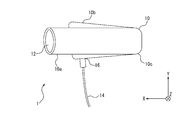
- FIG. 1 is a perspective view showing an appearance of a biosensor according to an embodiment.
- FIG. 2 is a view of the external appearance of the biosensor shown in FIG. 1 viewed from above. That is, FIG. 2 is a diagram showing a state in which the biological sensor shown in FIG. 1 is viewed in the negative direction of the Y axis.
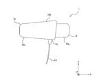
- FIG. 3 and FIG. 4 are views of the external appearance of the biosensor shown in FIG. 1 viewed from the side. That is, FIG. 3 is a diagram showing a state in which the biosensor shown in FIG. 1 is viewed in the positive direction of the Z axis. Further, FIG. 4 is a diagram showing a state in which the biological sensor shown in FIG. 1 is viewed in the negative direction of the Z axis. 1 to 4, the positive direction of the Y-axis shown in the drawings is also referred to as “up” direction as appropriate.
- the biosensor 1 includes a main body 10.
- the main body portion 10 includes a first mounting portion 10a, a second mounting portion 10b, and a coupling portion 10c.
- the first mounting portion 10a is an elongated portion extending substantially parallel to the X-axis direction shown in the figure.
- the second mounting portion 10b is an elongated portion extending substantially parallel to the X-axis direction shown in the drawing. 1 to 4, an example in which the first mounting portion 10a is configured to be longer than the second mounting portion 10b is shown, but these lengths may be appropriately changed.
- the coupling portion 10c couples the first mounting portion 10a and the second mounting portion 10b, as shown in FIGS. 1 to 4.
- the first mounting part 10a, the second mounting part 10b, and the coupling part 10c may be integrally formed.
- at least one of the first mounting portion 10a, the second mounting portion 10b, and the coupling portion 10c may be formed separately from other members.
- these members may be joined together by using an appropriate material such as an adhesive. Good.
- the body 10 of the biometric sensor 1 is attached to the subject's ear when measuring the biometric information of the subject, as described below. Therefore, in a state in which the main body 10 of the biometric sensor 1 is attached to the ear of the subject, the first attaching portion 10a, the second attaching portion 10b, so as to reduce the physical and physical burden imposed on the subject.
- At least one of the connecting portion 10c and the connecting portion 10c may be made of a flexible material.
- at least one of the first mounting portion 10a, the second mounting portion 10b, and the coupling portion 10c may be made of a soft material such as silicone rubber or urethane.
- the core portion is made of a hard material such as plastic or metal, and the surface portion is made of silicone rubber or urethane. It may be composed of a soft material.
- the body portion 10 of the biometric sensor 1 may be made of various materials that do not increase the physical and physical burden imposed on the subject more than necessary when the body part 10 is attached to the subject's ear.
- a sound output hole 12 that is a hole through which sound is output is formed at the end of the first mounting portion 10a opposite to the side connected to the connecting portion 10c.
- the first mounting section 10a may include a sound output section.
- the first mounting section 10a can output a sound or voice mainly in the positive direction of the X axis shown in the figure by incorporating a sound output section.
- the biosensor 1 may include a cable 14.
- the cable 14 may connect the biosensor 1 to an external device such as the measuring device 100 described later.
- the cable 14 may be configured to be attachable to and detachable from the main body of the biosensor 1.
- the cable 14 is not shown.
- the second mounting portion 10b of the main body portion 10 may include a cable connecting portion 16.
- the cable 14 may be connected to the cable connection 16.
- the cable 14 may be detachably attached to the cable connecting portion 16.
- the cable 14 is shown as an example connected to the second mounting portion 10b.
- the cable 14 may be connected to any place in the main body 10, such as the first mounting portion 10a or the coupling portion 10c.
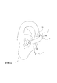
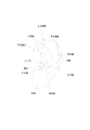
- FIG. 5 is a diagram showing a state in which the biometric sensor 1 is attached to the subject's ear (left ear). Further, for reference, FIG. 6 shows the names of the respective parts in a general human ear (left ear).
- the biometric sensor 1 can be attached to the ear of the subject.
- the first mounting portion 10a of the main body 10 may be mounted on the front side of the outer ear (ear shell), that is, on the side of the outer ear having the ear canal.
- the second mounting portion 10b of the main body 10 may be mounted on the back side of the outer ear (ear shell), that is, on the side of the outer ear that does not have the ear canal. More specifically, when the body 10 of the biometric sensor 1 is mounted on the ear of the subject, the first mounting portion 10a and the second mounting portion 10b may sandwich the earring portion of the subject.
- the earring portion of the subject is sandwiched by the first mounting portion 10a and the second mounting portion 10b with an appropriate pressure, so that the body portion 10 of the biosensor 1 is positioned at the position of the earring portion of the subject. Stable and maintained.
- FIG. 5 shows an example in which the biosensor 1 for the left ear is attached to the subject's left ear.
- the biosensor 1 for the right ear may be attached to the right ear of the subject by configuring the biosensor 1 for the right ear.
- the biosensor 1 configured for the right ear and the biosensor 1 configured for the left ear may be left-right symmetric (symmetric about the Z-axis direction shown in FIGS. 1 to 4). ..
- the main body portion 10 is configured to sandwich the earring portion of the subject between the first mounting portion 10a and the second mounting portion 10b. Therefore, according to the biometric sensor 1 according to the embodiment, when measuring the biometric information of the subject, the biometric information is stably measured while reducing the physical and physical burden imposed on the subject. be able to. Therefore, the biosensor according to the embodiment can improve convenience.
- the first mounting portion 10a and the second mounting portion 10b are shown as members that extend substantially linearly in the X-axis direction.
- at least one of the first mounting portion 10a and the second mounting portion 10b may be an appropriately curved member.
- the first mounting portion 10a may be curved so as to follow the shape of the depression of the scapha fossa when it is mounted on the subject's ear.
- the first mounting portion 10a may be curved so as to follow the shape of the protrusion of the annulus when it is mounted on the ear of the subject.
- the first mounting portion 10a may be curved so as to follow the shape of the depression of the concha of the ear when it is mounted on the ear of the subject.
- the second mounting portion 10b may also be curved so as to follow the shape of the back side of the outer ear (ear shell) when mounted on the ear of the subject. Further, at least one of the first mounting portion 10a and the second mounting portion 10b may be configured to have plasticity. In this case, at least one of the first mounting portion 10a and the second mounting portion 10b can be deformed according to the shape of the subject's ear.
- the end portion (sound output hole 12) of the first mounting portion 10a corresponds to the ear canal of the subject. It may be configured to be positioned in front of the entrance. That is, the first mounting unit 10a may be configured so that the sound output hole 12 is not inserted into the ear canal of the subject when the biosensor 1 is mounted on the ear of the subject. In this case, the ear canal of the subject is not blocked by the sound output hole 12. By doing so, the subject can listen to the sound of the surrounding environment while listening to the sound or voice output from the sound output hole 12. Therefore, the subject can considerably recognize the situation in the surroundings even while measuring the biometric information using the biometric sensor 1.
- the end portion (sound output hole 12) of the first attachment portion 10a is inspected. It may be configured to be inserted into the ear canal of a person. That is, the first mounting unit 10a may be configured such that the sound output hole 12 is inserted into the ear canal of the subject when the biosensor 1 is mounted on the ear of the subject.
- the first mounting portion 10a may be larger (longer) in size in the longitudinal direction than the state shown in FIG. In this case, the ear canal of the subject may be closed by the sound output hole 12.
- the subject can listen to the sound or voice output from the sound output hole 12 and can block the sound of the surrounding environment. Therefore, the subject can increase the immersive sensation while measuring the biometric information using the biometric sensor 1. Further, the subject can more clearly hear the sound or voice output from the sound output hole 12 while measuring the biological information using the biological sensor 1.
- the main body 10 of the biometric sensor 1 needs to be attachable to the subject's ear, and further, after being attached to the subject's ear, the subject's earring portion should be sandwiched with an appropriate force. Is also necessary.
- the biosensor 1 according to the embodiment may be configured such that at least a part of the main body 10 has elasticity.
- the coupling portion 10c of the main body portion 10 may have elasticity.
- This elasticity may give an elastic force such that the first mounting portion 10a and the second mounting portion 10b come close to each other.
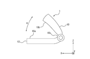
- the examinee or the inspector or the like opens the first mounting portion 10a and the second mounting portion 10b so as to open the main body portion 10 as a whole (in the direction of arrow A in FIG. 7).
- FIG. 7 is a diagram showing a state in which the first mounting portion 10a and the second mounting portion 10b of the body portion 10 of the biosensor 1 are opened.
- the subject or the inspector or the like attaches the first mounting portion 10a and the second mounting portion 10b to the subject's earring. It can be easily positioned with respect to the part.
- the subject or the inspector or the like forces the first mounting portion 10a and the second mounting portion 10b to open. Can be gradually weakened.
- the subject or the inspector releases the force that has opened the first mounting portion 10a and the second mounting portion 10b, the first mounting portion 10a and the second mounting portion 10b have the elastic force of the coupling portion 10c.
- the ear ring of the subject is pinched with an appropriate force.
- the coupling section 10c may couple the first mounting section 10a and the second mounting section 10b so as to be displaceable with respect to each other. Further, in the biosensor 1 according to the embodiment, the body portion 10 sandwiches the earring portion of the subject by the elasticity of at least one of the first mounting portion 10a, the second mounting portion 10b, and the coupling portion 10c. May be configured as.
- the coupling portion 10c may have a rotatable mechanism.
- the coupling portion 10c may apply a force in a direction in which the first mounting portion 10a and the second mounting portion 10b approach each other.
- the rotatable mechanism of the coupling portion 10c shown in FIG. 8 can be rotated by applying a predetermined force or more, but is configured so as not to rotate while being fixed even if a force less than the predetermined force is applied. Good.
- the examinee or the inspector applies a force of a predetermined amount or more to the first mounting portion 10a and the second mounting portion 10b to rotate the coupling portion 10c, so that the main body portion 10 is entirely ( (In the direction of arrow A in FIG. 8).
- FIG 8 is a diagram showing a state in which the first mounting portion 10a and the second mounting portion 10b of the body portion 10 of the biosensor 1 are opened to each other.
- the subject or the inspector or the like attaches the first mounting portion 10a and the second mounting portion 10b to the subject's earring. It can be easily positioned with respect to the part.
- the subject or the inspector again puts the first mounting portion 10a and the second mounting portion 10b above a predetermined amount or more.
- the main body 10 can be entirely closed by applying a force to rotate the connecting portion 10c.
- the subject or the inspector releases the force for closing the first mounting portion 10a and the second mounting portion 10b, the first mounting portion 10a and the second mounting portion 10b are covered by the elastic force of the coupling portion 10c.
- the examiner's earring part will be pinched with appropriate force.
- the biological sensor 1 can measure at least one of the percutaneous arterial blood oxygen saturation (SpO 2 ) and the blood flow of the subject. Therefore, the biological sensor 1 includes a measurement unit that measures at least one of the percutaneous arterial blood oxygen saturation (SpO 2 ) and the blood flow of the subject.
- FIG. 9 is a diagram exemplifying a configuration of a measurement unit of the biosensor 1 according to the embodiment.
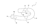
- the biosensor 1 may include a first light source 21, a second light source 22, and a light receiving unit 23.
- FIG. 9 shows a state in which the first light source 21, the second light source 22, and the light receiving section 23 are all built in the main body section 10. Therefore, the first light source 21, the second light source 22, and the light receiving unit 23 are shown by broken lines in FIG. 9.
- the first light source 21 and the second light source 22 will be appropriately referred to as light emitting units (21, 22).
- the first light source 21, the second light source 22, and the light receiving unit 23 will also be appropriately referred to as the measuring unit 20.
- the first light source 21 and the second light source 22 may emit laser light having a wavelength capable of detecting a predetermined component contained in blood as measurement light.
- the first light source 21 and the second light source 22 may each be configured by, for example, an LD (laser diode: laser diode).
- a laser light source used in this embodiment for example, a vertical cavity surface emitting laser (VCSEL: Vertical Surface Emitting Laser) may be used, but in addition, a distributed feedback laser (DFB: Distributed Feedback)
- DFB Distributed Feedback
- a Perot type laser (FP: Fabry-Perot) may be used.
- at least 1 side of the 1st light source 21 and the 2nd light source 22 may be comprised by LED (Light Emitting Diode: Light emitting diode) etc., for example.
- the first light source 21 and the second light source 22 emit laser light of different wavelengths.
- the first light source 21 emits laser light of a first wavelength (hereinafter also referred to as “first laser light”).
- the first wavelength is a wavelength having a large difference between the absorbance of hemoglobin bound to oxygen (hereinafter also referred to as “oxygenated hemoglobin”) and the absorbance of hemoglobin not bound to oxygen (hereinafter also referred to as “reduced hemoglobin”). ..
- the first wavelength is, for example, a wavelength of 600 nm to 700 nm, and the first laser light is so-called red light. In the present embodiment, description will be given below assuming that the first wavelength is 660 nm.
- the second light source 22 emits laser light of a second wavelength (hereinafter also referred to as “second laser light”).
- the second wavelength is a wavelength different from the first wavelength.
- the second wavelength is a wavelength at which the difference between the absorbance of oxygenated hemoglobin and the absorbance of reduced hemoglobin is smaller than that of the first wavelength.
- the second wavelength is, for example, a wavelength of 800 nm to 1000 nm, and the second laser light is so-called near infrared light. In the present embodiment, description will be given below assuming that the second wavelength is 850 nm.
- the light receiving unit 23 receives, as the biometric output, scattered light (detection light) of the measurement light irradiated on the test site, which is scattered from the test site.
- the light receiving unit 23 may be configured by, for example, a PD (photodiode).
- the light receiving unit 23 may be configured by a PD that can detect both wavelengths of red light and near infrared light.
- the biosensor 1 may transmit the photoelectric conversion signal of the scattered light received by the light receiving unit 23 to an external device via the cable 14, for example.
- the light emitting surfaces of the first light source 21 and the second light source 22 are arranged so as to be exposed from the second mounting portion 10b. Thereby, the 1st light source 21 and the 2nd light source 22 can irradiate a subject's ear ring part appropriately with light. Further, as shown in FIG. 9, the light receiving surface of the light receiving section 32 is arranged so as to be exposed from the first mounting section 10a. Accordingly, the light receiving unit 32 can appropriately receive the light, which is transmitted from at least one of the first light source 21 and the second light source 22 and has passed through the earring portion of the subject.
- the first light source 21 and the second light source 22, that is, the light emitting portions (21, 22) are arranged on the second mounting portion 10b side. Further, in the main body portion 10 of the biosensor 1 shown in FIG. 9, the light receiving portion 23 is arranged on the first mounting portion 10a side.
- the measuring unit 20 of the biosensor 1 constitutes a transmissive measuring unit. That is, in the measuring unit 20 of the biosensor 1, at least a part of the light emitted from the light emitting units (21, 22) passes through the earring portion of the subject and is received by the light receiving unit 23. Therefore, the measurement unit 20 of the biosensor 1 can measure at least one of the percutaneous arterial oxygen saturation (SpO 2 ) and the blood flow of the subject while being attached to the earring of the subject. it can.
- SpO 2 percutaneous arterial oxygen saturation
- the sound output part 30 may be incorporated inside the sound output hole 12 formed at the end of the first mounting part 10a.
- the sound output unit 30 may be composed of any member capable of transmitting sound or voice by at least one of air vibration and bone conduction.
- the sound output unit 30 may be configured by various members such as a dynamic receiver, a bone conduction receiver, or a smart sonic receiver.
- the sound output unit 30 can, for example, allow the subject to hear an arbitrary music or announcement of an instruction while the subject wears the biometric sensor 1 on the earring portion to measure biometric information. .. Further, the sound output unit 30 may output information based on the result of the biometric information measured by the biometric sensor 1 by sound or voice. For example, the sound output unit 30 may make the subject hear the measurement result of the biometric information by the biometric sensor 1 as a voice announcement. Further, for example, the sound output unit 30 may make the subject hear the measurement result of the biometric information by the biometric sensor 1 as a predetermined warning sound or music to call attention.
- the first mounting unit 10a may include the sound output unit 30 that outputs a sound from the end (sound output hole 12) of the first mounting unit 10a.
- the sound output unit 30 may transmit sound by at least one of air vibration and bone conduction.
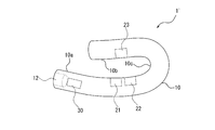
- FIG. 10 is a diagram illustrating a configuration of a measurement unit of a biosensor according to a modified example of the biosensor 1 illustrated in FIG. 9.
- a biosensor 1 ′ is the biosensor 1 shown in FIG. 9 in which the light emitting units (21, 22) and the light receiving unit 23 are reversed in position. . That is, in the body part 10 of the biosensor 1 ′ shown in FIG. 10, the first light source 21 and the second light source 22, that is, the light emitting parts (21, 22) are arranged on the first mounting part 10a side. Further, in the body portion 10 of the biosensor 1 ′ shown in FIG. 10, the light receiving portion 23 is arranged on the second mounting portion 10b side. Other configurations may be similar to those of the biosensor 1 shown in FIG.
- the measurement unit 20 of the biosensor 1 ′ also measures at least one of the percutaneous arterial oxygen saturation (SpO 2 ) and the blood flow of the subject while being attached to the earring of the subject.
- the light receiving unit 23 is arranged on the front side of the outer ear (auricle). For this reason, in the biosensor 1 ′ shown in FIG. 10, the light receiving unit 23 is less likely to receive light such as sunlight, that is, light other than the light emitted from the light emitting units (21, 22). Therefore, the biosensor 1 ′ shown in FIG. 10 can perform measurement with less noise.
- the light emitting parts (21, 22) are arranged in one of the first mounting part 10a and the second mounting part 10b, and the light receiving part 23 is mounted in the first mounting part It may be arranged on the other of the portion 10a and the second mounting portion 10b.
- FIG. 11 is a diagram exemplifying a configuration of a measurement unit of a biosensor according to another modification of the biosensor 1 shown in FIG.
- the first light source 21 and the second light source 22, that is, the light emitting parts (21, 22) and the light receiving part 23 are arranged on the second mounting part 10b side.
- Other configurations may be similar to those of the biosensor 1 or 1'shown in FIG. 9 or 10.
- the measurement unit 20 of the biosensor 2 constitutes a reflection type measurement unit. That is, in the measuring unit 20 of the biometric sensor 2, at least a part of the light emitted from the light emitting units (21, 22) is reflected by the living body of the ear ring of the subject and is received by the light receiving unit 23.
- the measurement unit 20 of the biometric sensor 2 can measure at least one of the percutaneous arterial oxygen saturation (SpO2) and the blood flow of the subject while being attached to the earring of the subject. .
- the measurement unit 20 may measure SpO 2 and blood flow rate at the same time.
- FIG. 12 is a diagram illustrating a configuration of a measurement unit of a biosensor according to a modified example of the biosensor 2 illustrated in FIG. 11.
- a biosensor 2 ′ is the biosensor 2 shown in FIG. 11 in which the position of the measurement unit 20 is reversed. That is, in the body part 10 of the biosensor 2 ′ shown in FIG. 12, the first light source 21 and the second light source 22, that is, the light emitting parts (21, 22) and the light receiving part are not mounted on the second mounting part 10b side but on the first mounting part 10b. It is arranged on the side of the portion 10a. Other configurations may be the same as the biosensor 2 shown in FIG. 11. Therefore, the measurement unit 20 of the biometric sensor 2 ′ should also measure at least one of the percutaneous arterial oxygen saturation (SpO 2 ) and blood flow of the subject while being attached to the earring of the subject.
- SpO 2 percutaneous arterial oxygen saturation
- the light receiving unit 23 is arranged on the front side of the outer ear (auricle). For this reason, in the biological sensor 2 ′ shown in FIG. 12, the light receiving unit 23 is less likely to receive light such as sunlight, that is, light other than the light emitted from the light emitting units (21, 22). Therefore, the biosensor 2 ′ shown in FIG. 12 can perform measurement with less noise.
- both the light emitting parts (21, 22) and the light receiving part 23 are arranged in one of the first mounting part 10a and the second mounting part 10b. Good.
- the biosensor 1 includes the measurement unit 20.
- the measurement unit 20 measures at least one of the percutaneous arterial oxygen saturation (SpO 2 ) and the blood flow of the subject.
- the measurement unit 20 may include a light emitting unit (21, 22) and a light receiving unit 23.
- the light emitting unit (21, 22) may include the first light source 21 and the second light source 22. Therefore, according to the biometric sensor 1 according to the embodiment, the biometric information of the subject can be stably measured when the biometric information of the subject is measured. Therefore, the biosensor according to the embodiment can improve convenience.
- the measuring unit 20 includes at least one of the first mounting unit 10 a and the second mounting unit 10 b. May be located at.
- FIG. 13 is a functional block diagram showing a schematic configuration of the biosensor 1 shown in FIG. 9 and the measuring device 100 connected to the biosensor 1.
- the biological sensor 1 includes a first light source 21, a second light source 22, a light receiving section 23, and a sound output section 30. Since these functional units have already been described, a more detailed description will be omitted.
- the biometric sensor 1 may be connected to the measuring device 100 which is an external device.
- the biosensor 1 may be connected to the measuring device 100 via the cable 14.
- the biosensor 1 may have all or at least a part of the measurement device 100 shown in FIG. 13 integrally in the biosensor 1.
- the measuring apparatus 100 may include a control unit 101, a storage unit 103, a communication unit 105, an input unit 107, and a display unit 109.
- the measuring apparatus 100 may be any external device connectable to the biosensor 1.
- the measuring device 100 may be a dedicated terminal for connecting to the biosensor 1.
- the measuring device 100 may be any existing electronic device such as a smartphone, a tablet terminal, a notebook computer, or a general-purpose computer. In this case, these electronic devices may be activated with application software for measuring the biometric information of the subject by the biometric sensor 1 and estimating the state of the subject based on the measured biometric information. ..
- the biosensor 1 may be supplied with power from an internal battery or an external power supply.
- the control unit 101 controls and manages at least one of the biometric sensor 1 and the measuring apparatus 100, including at least one functional block of the biometric sensor 1 and the measuring apparatus 100.
- the control unit 101 may be configured to include at least one processor, for example.
- the control unit 101 is configured to include at least one processor such as a CPU (Central Processing Unit) that executes a program that defines a control procedure, and realizes its function.
- a program may be stored in, for example, the storage unit 103, an external storage medium connected to the measuring apparatus 100, or the like.
- At least one processor may be implemented as a single integrated circuit (IC) or as multiple communicatively connected integrated circuits ICs and / or discrete circuits. Good.
- the at least one processor can be configured according to various known techniques.
- a processor includes one or more circuits or units configured to perform one or more data calculation procedures or processes, such as by executing instructions stored in associated memory.
- the processor may be firmware (eg, discrete logic component) configured to perform one or more data calculation procedures or processes.
- the processor is one or more processors, controllers, microprocessors, microcontrollers, application specific integrated circuits (ASICs), digital signal processors, programmable logic devices, field programmable gate arrays, or the like. It may include any combination of devices or configurations, or any combination of other known devices or configurations, to perform the function as the control unit 101 described below.
- ASICs application specific integrated circuits
- digital signal processors programmable logic devices, field programmable gate arrays, or the like. It may include any combination of devices or configurations, or any combination of other known devices or configurations, to perform the function as the control unit 101 described below.
- the control unit 101 controls, for example, a biological information measurement process.
- the control unit 101 controls the measurement process of the subject's SpO 2 by the biosensor 1.
- the control unit 101 may estimate the state of the subject based on the measured information.
- the control unit 101 may estimate the possibility that the subject will have altitude sickness (also referred to as severe disability) based on the measured SpO 2 of the subject. Altitude sickness is more likely to develop due to a decrease in SpO 2 .
- the control unit 101 may inform the subject via the sound output unit 30 by controlling the sound output unit 30 with the measured biological information and / or the estimated possibility of becoming altitude sickness.
- the control unit 101 may notify the subject of such information via the display unit 109 by controlling the display unit 109.
- the subject can know the notified information. For example, when the subject is informed that there is a high possibility that he will have altitude sickness, he can take measures to prevent altitude sickness in advance.
- the storage unit 103 can be composed of a semiconductor memory, a magnetic memory, or the like.
- the storage unit 103 stores various kinds of information, programs for operating the measuring apparatus 100, and the like.
- the storage unit 103 may also function as a work memory.
- the storage unit 103 may store, for example, the subject's body temperature and SpO 2 calculated by the control unit 101 as history information.
- the storage unit 103 may store information about the possibility of becoming altitude sickness estimated by the control unit 101.
- the storage unit 103 may store information about the sound output by the sound output unit 160.
- the sound information stored in the storage unit 103 may be an audio file of any format such as an MP3 (MPEG-1 Audio Layer-3) file or a WAV file.
- the storage unit 103 may store information of various sounds according to the state of the subject who is using the measurement apparatus 100.
- the communication unit 105 transmits and receives various data by performing wired communication or wireless communication with an external device such as the biometric sensor 1 or an external server.
- the communication unit 304 can send and receive information using a network that is wireless, wired, or a combination of wireless and wired.
- the communication unit 105 can perform communication using, for example, Bluetooth (registered trademark), infrared ray, NFC, wireless LAN, wired LAN, or any other communication medium or any combination thereof.
- the communication unit 105 may communicate with an external device that stores the biometric information of the subject in order to manage the health condition, for example.
- the communication unit 105 may transmit the result measured by the biosensor 1 and / or the health condition estimated by the measurement device 100 to the external device.
- the communication unit 105 may be an interface for connecting the cable 14, for example.
- the input unit 107 may be configured to include a physical key such as a keyboard, or may be configured to include a touch panel.
- the input unit 107 is not limited to these, and may be configured to include various input devices.
- the measurement apparatus 100 may start the control related to the biometric sensor 1 measuring the biometric information of the subject based on the operation input of the operator on the input unit 107.
- the display unit 109 notifies information by characters or images.
- the display unit 109 may be a display device such as a liquid crystal display (LCD: Liquid Crystal Display), an organic EL display (OELD: Organic Electro-Luminescence Display), or an inorganic EL display (IELD: Inorganic Electro-Luminescence Display).
- the display unit 109 may display the biometric information of the subject measured by the biometric sensor 1 and / or various information based on the biometric information. Thereby, the subject or the inspector can recognize the biometric information of the subject and / or various information based on the biometric information.
- the display unit 109 may display the information output from the sound output unit 30 as information such as characters or images.
- FIG. 14 is a flowchart showing the operation executed by the measuring apparatus 100.
- the measuring device 100 When the subject wears the biosensor 1 connected to the measuring device 100 on his / her ear and performs an input operation for executing the measuring process on the input unit 107, the measuring device 100 is, for example, as illustrated in FIG. The operation shown in may be started.
- the control unit 101 of the measurement device 100 measures biometric information (step S1). Specifically, the measuring apparatus 100 measures the biological information in the earring part of the subject by the measuring unit 20 of the biological sensor 1.
- the biological information measured by the measuring unit 20 of the biological sensor 1 may be, for example, SpO 2 of the subject.
- the information on SpO 2 measured by the measurement unit 20 of the biosensor 1 is transmitted to the control unit 101 of the measurement device 100.
- the measuring apparatus 100 may store the result of measurement by the measuring unit 20 of the biosensor 1 in, for example, the storage unit 103.
- the control unit 101 of the measuring apparatus 100 estimates the state of the subject based on the measured biological information (step S2). Specifically, the control unit 101 may estimate the possibility that the subject will have altitude sickness, for example, based on the SpO 2 of the subject.
- the control unit 101 of the measurement device 100 may estimate the state of the subject based on the information measured by the measurement unit 20 of the biosensor 1. For example, the control unit 101 may estimate that there is a high possibility that the subject will have altitude sickness if the SpO 2 of the subject exceeds a predetermined threshold value or if a predetermined condition is satisfied. In addition, for example, the control unit 101 may estimate that the subject is in a predetermined health state when SpO 2 of the subject is within a predetermined range.
- the control unit 101 notifies the subject of information via the sound output unit 30 by transmitting a control signal to the sound output unit 30 (step S3).
- the control unit 101 may notify the information by making the subject hear a predetermined sound or voice.
- the measuring apparatus 100 may repeatedly execute steps S1 to S3 regularly, irregularly, or continuously. Thereby, the measuring apparatus 100 can continuously acquire the biological information of the subject and the history of the state of the subject.
- the measuring apparatus 100 may notify the information in step S3 by means other than the sound output unit 30.
- the measuring apparatus 100 may notify the information by displaying the information on the display unit 109.
- the measuring apparatus 100 may notify the information by any other means that can be recognized by the subject.
- the biosensor 1 outputs information based on at least one of the percutaneous arterial blood oxygen saturation (SpO 2 ) and the blood flow of the subject measured by the measurement unit 20, to the sound output unit 30. May be output as at least one of sound and voice.
- SpO 2 percutaneous arterial blood oxygen saturation
- the biometric sensor 1 described in FIG. 13 has been described as having a function of measuring the biometric information of the subject and a function of outputting sound or voice to the subject's ear. That is, the biosensor 1 described in FIG. 13 does not have a function of processing biometric information, and the measurement device 100 connected to the biosensor 1 processes biometric information.
- biometric sensor may itself have a function of processing biometric information.
- biometric information may itself have a function of processing biometric information.
- FIG. 15 is a functional block diagram showing a schematic configuration of a biosensor according to another embodiment.
- a biosensor 3 according to another embodiment includes a first light source 21, a second light source 22, a light receiving unit 23, a sound output unit 30, a temperature detecting unit 40, and a control unit 50. And a communication unit 60. Since the first light source 21, the second light source 22, the light receiving unit 23, and the sound output unit 30 have already been described, a more detailed description will be omitted.
- the biosensor 3 may include a temperature detection unit 40 as shown in FIG.
- the temperature detection unit 40 may be any temperature sensor that can detect the temperature of a contacting portion such as a thermistor.
- the temperature detection unit 40 may be arranged in the main body unit 10 at any position where the body temperature of the subject can be detected.
- the temperature detection unit 40 may be arranged near the measurement unit 20 in at least one of the first mounting unit 10a and the second mounting unit 10b. By arranging in this way, the temperature detection unit 40 can detect the temperature in the earring portion of the subject, that is, the body temperature of the subject.
- the biometric sensor 3 may output the information about the body temperature of the subject detected by the temperature detection unit 40, for example, as sound or voice from the sound output unit 30. In addition, the biometric sensor 3 may consider the body temperature of the subject detected by the temperature detection unit 40 when estimating the state of the subject.
- the control unit 50 may be a functional unit that executes the same function as the control unit 101 of the measuring apparatus 100 shown in FIG.
- the biometric sensor 3 may include the control unit 50 as described above at an arbitrary position of the main body unit 10.
- the second mounting portion 10b of the main body portion 10 may be formed to have a larger size than the first mounting portion 10a, and the small-sized control portion 50 may be built therein.
- the biosensor 3 performs a predetermined process on information about at least one of the percutaneous arterial blood oxygen saturation (SpO 2 ) and the blood flow of the subject measured by the measurement unit 20.
- the unit 50 may be provided.
- the biometric sensor 3 does not have to be connected to an external device such as the measurement apparatus 100 shown in FIG. 13 and is based on the biometric information of the test subject measured by the measurement unit 20.
- the state of can be estimated. That is, the biometric sensor 3 can execute a complete function independently without connecting to an external device.
- the biological sensor 3 outputs information based on at least one of the percutaneous arterial blood oxygen saturation (SpO 2 ) and the blood flow volume of the subject measured by the measurement unit 20, from the sound output unit 30. And may be output as at least one of voice.
- SpO 2 percutaneous arterial blood oxygen saturation
- the communication unit 60 may be a functional unit that executes the same function as the communication unit 105 of the measuring device 100 shown in FIG.
- the biometric sensor 3 may transmit the measurement result of the biometric sensor 1 and / or the health condition estimated by the control unit 50 to an external device such as an external server.
- the biometric sensor 3 may include the communication unit 60 that connects to an external terminal device in a wired or wireless manner. Further, when the biometric sensor 1 is connected to an external device via the cable 14, the communication unit 60 may be an interface for connecting the cable 14, for example.
- the biometric sensor according to the embodiment when measuring the biometric information of the subject, the biometric information can be stably provided while reducing the physical and physical burden imposed on the subject. Can be measured. Therefore, the biosensor according to the embodiment can improve convenience.
- the biometric sensor according to one embodiment can be attached to the ear of the subject to perform measurement with almost the same luminous intensity as when the biometric information of the subject is measured by irradiating the earlobe with light. Therefore, according to the biosensor according to the embodiment, it is possible to perform measurement with a smaller luminous intensity than in the case where the fingertip of the subject is irradiated with light for measurement. Therefore, according to the biosensor according to the embodiment, it is possible to realize lower power consumption than the conventional general measuring device.
- the biometric sensor according to one embodiment can measure biometric information in a natural state of the subject without imposing an unreasonable posture or posture on the subject without giving the subject a feeling of discomfort. To Therefore, the biometric sensor according to one embodiment can minimize the burden on the subject such as fatigue. Further, since the biosensor according to the embodiment is configured to be wearable, it can be used even when the subject is moving, such as during exercise. Further, according to the biometric sensor according to the embodiment, the biosensor can be stably positioned at the earring portion of the subject, and thus the measurement of the biometric information of the subject can be stabilized.
- the embodiment according to the present disclosure can be realized as a method executed by a processor included in the device, a program, or a storage medium storing the program. It should be understood that these are also included in the scope of the present disclosure.
- the present disclosure has been described based on the drawings and the embodiments, it should be noted that those skilled in the art can easily make various variations or modifications based on the present disclosure. Therefore, it should be noted that these variations or modifications are included in the scope of the present disclosure.
- the functions included in each functional unit can be rearranged so as to be logically consistent.
- the plurality of functional units and the like may be combined into one or divided.
- each functional unit, each unit, each step, or the like is added to another embodiment so as not to logically contradict, or each functional unit, each unit, or each step of another embodiment. It can be replaced with Further, in each of the embodiments, it is possible to combine or divide a plurality of each functional unit, each unit, each step, and the like into one.
- each of the embodiments of the present disclosure described above is not limited to being faithfully performed in each of the described embodiments, and may be implemented by appropriately combining the features or omitting a part thereof. You can also
Landscapes
- Health & Medical Sciences (AREA)
- Life Sciences & Earth Sciences (AREA)
- Physics & Mathematics (AREA)
- Engineering & Computer Science (AREA)
- Molecular Biology (AREA)
- General Health & Medical Sciences (AREA)
- Biophysics (AREA)
- Pathology (AREA)
- Veterinary Medicine (AREA)
- Biomedical Technology (AREA)
- Heart & Thoracic Surgery (AREA)
- Medical Informatics (AREA)
- Public Health (AREA)
- Surgery (AREA)
- Animal Behavior & Ethology (AREA)
- Physiology (AREA)
- Cardiology (AREA)
- Otolaryngology (AREA)
- Hematology (AREA)
- Spectroscopy & Molecular Physics (AREA)
- Optics & Photonics (AREA)
- Audiology, Speech & Language Pathology (AREA)
- Computer Networks & Wireless Communication (AREA)
- Pulmonology (AREA)
- Measuring Pulse, Heart Rate, Blood Pressure Or Blood Flow (AREA)
- Measurement Of The Respiration, Hearing Ability, Form, And Blood Characteristics Of Living Organisms (AREA)
Abstract
生体センサは、本体部と、測定部とを備える。本体部は、第1装着部及び第2装着部によって被検者の耳輪部分を挟むように構成される。測定部は、被検者の経皮的動脈血酸素飽和度(SpO2)及び血流量の少なくとも一方を測定する。
Description
本出願は、2018年11月15日に日本国に特許出願された特願2018-214807の優先権を主張するものであり、この先の出願の開示全体を、ここに参照のために取り込む。
本開示は、生体センサに関する。
従来、人体に装着して生体情報を測定する測定装置が知られている。例えば特許文献1には、耳に装着して生体情報を検出し、検出した生体情報に基づいて血流状態値を算出する耳装着型装置が開示されている。
一実施形態に係る生体センサは、本体部と、測定部と、を備える。
前記本体部は、第1装着部及び第2装着部によって被検者の耳輪部分を挟むように構成される。
前記測定部は、被検者の経皮的動脈血酸素飽和度(SpO2)及び血流量の少なくとも一方を測定する。
前記本体部は、第1装着部及び第2装着部によって被検者の耳輪部分を挟むように構成される。
前記測定部は、被検者の経皮的動脈血酸素飽和度(SpO2)及び血流量の少なくとも一方を測定する。
被検者の生体情報を測定する際に、被検者に課される心身の負担を軽減しつつ、安定して生体情報を測定できれば、測定機器の利便性を向上することができる。本開示の目的は、利便性を向上可能な生体センサを提供することにある。本開示によれば、利便性を向上可能な生体センサを提供することができる。以下、一実施形態に係る生体センサについて、図面を参照して詳細に説明する。
一実施形態に係る生体センサは、被検者の生体情報を測定する際に、被検者の耳に装着される。一実施形態に係る生体センサは、被検者の耳に装着された状態で、被検者の生体情報を測定する。ここで、生体情報は、生体に関する任意の情報であり、例えば、酸素飽和度、経皮的動脈血酸素飽和度(SpO2)、体温、脈拍数、呼吸数、PI(Perfusion Index)値、血流量、及び血圧等を含んでよい。また、生体情報は、例えば生体の心身のリラックス度合いを示唆するリラックス度などを含んでもよい。生体センサ1は、測定した生体情報に基づき、被検者の状態を推定してよい。被検者の状態は、被検者の生体に生じる任意の状態であり、例えば、高山病になる可能性を含む。
図1は、一実施形態に係る生体センサの外観を示す斜視図である。図2は、図1に示す生体センサの外観を上方から見た図である。すなわち、図2は、図1に示す生体センサを、Y軸の負方向に向かって見た状態を示す図である。図3及び図4は、図1に示す生体センサの外観を側方から見た図である。すなわち、図3は、図1に示す生体センサを、Z軸の正方向に向かって見た状態を示す図である。また、図4は、図1に示す生体センサを、Z軸の負方向に向かって見た状態を示す図である。図1乃至図4において、図に示すY軸の正方向を、適宜、「上」方向とも記す。
図1乃至図4に示すように、一実施形態に係る生体センサ1は、本体部10を備えている。本体部10は、図1乃至図4に示すように、第1装着部10aと、第2装着部10bと、結合部10cと、を備えている。
第1装着部10aは、図に示すX軸方向にほぼ平行に延在する細長形状の部分である。第2装着部10bは、図に示すX軸方向にほぼ平行に延在する細長形状の部分である。図1乃至図4において、第1装着部10aは第2装着部10bよりも長く構成した例を示してあるが、これらの長さは適宜変更してもよい。また、結合部10cは、図1乃至図4に示すように、第1装着部10aと第2装着部10bとを結合している。
本体部10において、第1装着部10a、第2装着部10b、及び結合部10cは、一体形成されてもよい。一方、本体部10において、第1装着部10a、第2装着部10b、及び結合部10cの少なくともいずれかは、他の部材とは別に形成されてもよい。第1装着部10a、第2装着部10b、及び結合部10cの少なくともいずれかが他の部材と別に形成された場合、それらの部材は例えば接着剤などの適切な材料を用いて結合させてもよい。
生体センサ1の本体部10は、後述のように、被検者の生体情報を測定する際に、被検者の耳に装着される。そこで、生体センサ1の本体部10が被検者の耳に装着された状態において、被検者に課される心身の負担を軽減するように、第1装着部10a、第2装着部10b、及び結合部10cの少なくともいずれかは、柔軟性のある素材で構成されてもよい。例えば、第1装着部10a、第2装着部10b、及び結合部10cの少なくともいずれかは、シリコンゴム又はウレタンなどの柔らかい素材で構成されてもよい。一方、第1装着部10a、第2装着部10b、及び結合部10cの少なくともいずれかは、芯となる部分はプラスチック又は金属などの硬質の材料で構成され、表面部分はシリコンゴム又はウレタンなどの柔らかい素材で構成されてもよい。生体センサ1の本体部10は、被検者の耳に装着された状態において、被検者に課される心身の負担を必要以上の増大させないような各種の材料で構成されてよい。
図1乃至図4に示すように、第1装着部10aの結合部10cに結合されている側とは反対側の端部に、音が出力される孔である音出力孔12が形成されてもよい。後述するように、第1装着部10aは、音出力部を内蔵してもよい。第1装着部10aは、音出力部を内蔵することにより、主として図に示すX軸の正方向に音又は音声などを出力することができる。
図1、図3、及び図4に示すように、生体センサ1は、ケーブル14を備えてもよい。この場合、ケーブル14は、生体センサ1を例えば後述の測定装置100のような外部機器に接続してもよい。また、ケーブル14は、生体センサ1の本体部と着脱可能に構成されてもよい。図2において、ケーブル14は、図示を省略してある。また、図3及び図4に示すように、本体部10の第2装着部10bは、ケーブル接続部16を備えてもよい。この場合、ケーブル14は、ケーブル接続部16に接続されてよい。また、この場合も、ケーブル14は、ケーブル接続部16に着脱可能に構成されてもよい。図1、図3、及び図4において、ケーブル14は、第2装着部10bに接続される例を示してある。しかしながら、ケーブル14は、例えば第1装着部10a又は結合部10cなど、本体部10における任意の箇所に接続されてもよい。
図5は、生体センサ1が被検者の耳(左耳)に装着された状態を示す図である。また、参考までに、図6に、一般的な人間の耳(左耳)における各部の名称を記す。
図5に示すように、生体センサ1は、被検者の耳に装着することができる。この場合、本体部10のうち第1装着部10aを、外耳(耳殻)の表側、すなわち外耳において外耳道を有する側に装着させてよい。また、本体部10のうち第2装着部10bを、外耳(耳殻)の裏側、すなわち外耳において外耳道を有さない側に装着させてよい。より詳細には、生体センサ1の本体部10を被検者の耳に装着する際、第1装着部10a及び第2装着部10bが、被検者の耳輪部分を挟むようにしてよい。このように、第1装着部10a及び第2装着部10bによって被検者の耳輪部分が適度な圧力で挟まれることにより、生体センサ1の本体部10は、被検者の耳輪部分の位置に安定して維持される。
図5は、左耳用の生体センサ1を被検者の左耳に装着した例を示している。しかしながら、一実施形態において、生体センサ1を右耳用に構成することにより、右耳用の生体センサ1を被検者の右耳に装着してもよい。この場合、右耳用に構成される生体センサ1と、左耳用に構成された生体センサ1とは、左右対称(図1乃至図4に示すZ軸方向について対称)になるようにしてよい。
このように、一実施形態に係る生体センサ1において、本体部10は、第1装着部10a及び第2装着部10bによって被検者の耳輪部分を挟むように構成される。このため、一実施形態に係る生体センサ1によれば、被検者の生体情報を測定する際に、被検者に課される心身の負担を軽減しつつ、安定して生体情報を測定することができる。したがって、一実施形態に係る生体センサによれば、利便性を向上させることができる。
図1乃至図5において、第1装着部10a及び第2装着部10bは、X軸方向にほぼ直線状に延在する部材として示してある。しかしながら、第1装着部10a及び第2装着部10bの少なくとも一方は、適度に湾曲させた部材としてもよい。例えば、第1装着部10aは、被検者の耳に装着される際に、舟状窩のくぼみの形状に沿うように湾曲させてもよい。また、第1装着部10aは、被検者の耳に装着される際に、対耳輪の隆起の形状に沿うように湾曲させてもよい。さらに、第1装着部10aは、被検者の耳に装着される際に、耳甲介のくぼみの形状に沿うように湾曲させてもよい。また、第2装着部10bも、被検者の耳に装着される際に、外耳(耳殻)の裏側の形状に沿うように湾曲させてもよい。さらに、第1装着部10a及び第2装着部10bの少なくとも一方が塑性(可塑性)を有するように構成してもよい。この場合、第1装着部10a及び第2装着部10bの少なくとも一方は、被検者の耳の形状に合わせて変形させることができる。
また、図5に示すように、生体センサ1の本体部10が被検者の耳に装着された際に、第1装着部10aの端部(音出力孔12)が被検者の外耳道の入口手前に位置付けられるように構成してもよい。すなわち、第1装着部10aは、生体センサ1が被検者の耳に装着された際、音出力孔12が被検者の外耳道に挿入されないように構成してもよい。この場合、被検者の外耳道は、音出力孔12によって塞がれない。このようにすれば、被検者は、音出力孔12から出力される音又は音声に耳を傾けつつも、周囲環境の音も聞くことができる。したがって、被検者は、生体センサ1を使用して生体情報を測定している間であっても、周囲における状況を相当程度認識することができる。
一方、図5に示す実施形態の変形例として、生体センサ1の本体部10が被検者の耳に装着された際に、第1装着部10aの端部(音出力孔12)が被検者の外耳道に挿入されるように構成してもよい。すなわち、第1装着部10aは、生体センサ1が被検者の耳に装着された際、音出力孔12が被検者の外耳道に挿入されるように構成してもよい。例えば、第1装着部10aは、図5に示す状態よりも長手方向のサイズを大きく(長く)してもよい。また、この場合、被検者の外耳道は、音出力孔12によって塞がれるように構成してもよい。このようにすれば、被検者は、音出力孔12から出力される音又は音声に耳を傾けることができ、かつ、周囲環境の音を遮断することができる。したがって、被検者は、生体センサ1を使用して生体情報を測定している間、没入感を高めることができる。また、被検者は、生体センサ1を使用して生体情報を測定している間、音出力孔12から出力される音又は音声を、より鮮明に聞くことができる。
次に、生体センサ1を被検者の耳に装着するための機構について説明する。
生体センサ1の本体部10は、まず、被検者の耳に装着できる必要があり、さらに、被検者の耳に装着された後は、被検者の耳輪部分を適度な力で挟むことも必要である。このような構成を実現するために、一実施形態に係る生体センサ1は、例えば、本体部10の少なくとも一部分が弾性を有するように構成してもよい。
例えば、図7に示すように、本体部10のうち結合部10cが弾性を有してもよい。この弾性は、第1装着部10aと第2装着部10bとが互いに近接するような弾性力を付与するとしてもよい。この場合、被検者又は検査者などは、第1装着部10aと第2装着部10bとを互いに開くようにして、本体部10を全体的に(図7の矢印Aの方向に)広げることができる。図7は、生体センサ1の本体部10において、第1装着部10aと第2装着部10bとが互いに開かれた状態を示す図である。このように、第1装着部10aと第2装着部10bとが互いに開かれた状態において、被検者又は検査者などは、第1装着部10a及び第2装着部10bを被検者の耳輪部分に対して容易に位置決めすることができる。第1装着部10a及び第2装着部10bを被検者の耳輪部分に対して位置決めしたら、被検者又は検査者などは、第1装着部10aと第2装着部10bとを開いていた力を徐々に弱めることができる。そして、被検者又は検査者などが第1装着部10aと第2装着部10bとを開いていた力を解除すると、第1装着部10a及び第2装着部10bは、結合部10cの弾性力によって被検者の耳輪部分を適度な力で挟むようになる。
このように、一実施形態に係る生体センサ1において、結合部10cは、第1装着部10aと第2装着部10bとを互いに対して変位可能に結合してもよい。また、一実施形態に係る生体センサ1において、本体部10は、第1装着部10a、第2装着部10b、及び結合部10cの少なくともいずれかの弾性によって、被検者の耳輪部分を挟むように構成されてもよい。
また、図8に示すように、結合部10cは、回動可能な機構を有してもよい。この結合部10cは、第1装着部10aと第2装着部10bとが互いに近接する方向の力を付与するとしてもよい。図8に示す結合部10cの回動可能な機構は、所定以上の力を加えると回動させることができるが、所定未満の力を加えても固定されたまま回動しないように構成してよい。この場合、被検者又は検査者などは、第1装着部10aと第2装着部10bとに所定以上の力を加えて結合部10cを回動させることにより、本体部10を全体的に(図8の矢印Aの方向に)広げることができる。図8は、生体センサ1の本体部10において、第1装着部10aと第2装着部10bとが互いに開かれた状態を示す図である。このように、第1装着部10aと第2装着部10bとが互いに開かれた状態において、被検者又は検査者などは、第1装着部10a及び第2装着部10bを被検者の耳輪部分に対して容易に位置決めすることができる。第1装着部10a及び第2装着部10bを被検者の耳輪部分に対して位置決めしたら、被検者又は検査者などは、第1装着部10aと第2装着部10bとに再び所定以上の力を加えて結合部10cを回動させて、本体部10を全体的に閉じることができる。そして、被検者又は検査者などが第1装着部10aと第2装着部10bとを閉じる力を解除すると、第1装着部10a及び第2装着部10bは、結合部10cの弾性力によって被検者の耳輪部分を適度な力で挟むようになる。
次に、生体センサ1の測定部について説明する。
生体センサ1は、被検者の経皮的動脈血酸素飽和度(SpO2)及び血流量の少なくとも一方を測定することができる。このため、生体センサ1は、被検者の経皮的動脈血酸素飽和度(SpO2)及び血流量の少なくとも一方を測定する測定部を備えている。
図9は、一実施形態に係る生体センサ1の測定部の構成を例示する図である。
図9に示すように、一実施形態に係る生体センサ1は、第1光源21と、第2光源22と、受光部23とを備えてよい。図9は、第1光源21、第2光源22、及び受光部23が、いずれも本体部10に内蔵されている状態を示している。このため、第1光源21、第2光源22、及び受光部23は、図9において破線により示してある。以下、第1光源21及び第2光源22を、適宜、発光部(21,22)のようにも記す。また、以下、第1光源21、第2光源22、及び受光部23を、適宜、測定部20とも記す。
第1光源21及び第2光源22は、血液中に含まれる所定の成分を検出可能な波長のレーザ光を測定光として射出してよい。第1光源21及び第2光源22は、例えばそれぞれLD(レーザダイオード:Laser Diode)により構成されてよい。本実施形態で利用されるレーザ光源として、例えば、垂直共振器型面発光レーザ(VCSEL:Vertical Cavity Surface Emitting Laser)を用いてもよいが、その他、分布帰還型レーザ(DFB:Distributed Feedback)、ファブリペロー型レーザ(FP:Fabry-Perot)を用いてもよい。一実施形態において、第1光源21及び第2光源22の少なくとも一方は、例えばLED(発光ダイオード:Light Emitting Diode)などにより構成されてもよい。
第1光源21及び第2光源22は、それぞれ異なる波長のレーザ光を射出する。第1光源21は、第1波長のレーザ光(以下「第1レーザ光」とも称する)を射出する。第1波長は、酸素と結合したヘモグロビン(以下「酸素化ヘモグロビン」とも称する)の吸光度と、酸素と結合していないヘモグロビン(以下「還元ヘモグロビン」とも称する)の吸光度との差分が大きい波長である。第1波長は、例えば600nmから700nmの波長であり、第1レーザ光は、いわゆる赤色光である。本実施形態では、第1波長が660nmであるとして以下説明する。第2光源22は、第2波長のレーザ光(以下「第2レーザ光」とも称する)を射出する。第2波長は、第1波長と異なる波長である。第2波長は、第1の波長と比べて、酸素化へモグロビンの吸光度と還元ヘモグロビンの吸光度との差分が小さい波長である。第2波長は、例えば800nmから1000nmの波長であり、第2レーザ光は、いわゆる近赤外光である。本実施形態では、第2波長が850nmであるとして以下説明する。
受光部23は、生体測定出力として、被検部位に照射された測定光の、被検部位から散乱される散乱光(検出光)を受光する。受光部23は、例えばPD(フォトダイオード:Photo Diode)により構成されてよい。一実施形態において、受光部23は、赤色光及び近赤外光の両方の波長を検知できるPDにより構成されてもよい。生体センサ1は、受光部23において受光した散乱光の光電変換信号を、例えばケーブル14を介して外部機器に送信してよい。
図9に示すように、第1光源21及び第2光源22の発光面は、第2装着部10bから露出するように配置される。これにより、第1光源21及び第2光源22は、被検者の耳輪部分に適切に光を照射することができる。また、図9に示すように、受光部32の受光面は、第1装着部10aから露出するように配置される。これにより、受光部32は、第1光源21及び第2光源22の少なくとも一方から照射された光のうち、被検者の耳輪部分を透過した光を適切に受光することができる。
図9に示す生体センサ1の本体部10において、第1光源21及び第2光源22すなわち発光部(21,22)は第2装着部10b側に配置されている。また、図9に示す生体センサ1の本体部10において、受光部23は第1装着部10a側に配置されている。このような配置により、生体センサ1の測定部20は透過型の測定部を構成する。すなわち、生体センサ1の測定部20において、発光部(21,22)から照射された光の少なくとも一部は、被検者の耳輪部分を透過して、受光部23において受光される。したがって、生体センサ1の測定部20は、被検者の耳輪部分に装着された状態で、被検者の経皮的動脈血酸素飽和度(SpO2)及び血流量の少なくとも一方を測定することができる。
また、図9に示すように、第1装着部10aの端部に形成された音出力孔12の内部には、音出力部30を内蔵させてもよい。ここで、音出力部30は、空気振動及び骨伝導の少なくとも一方によって、音又は音声を伝えることができる任意の部材で構成してよい。例えば、音出力部30は、ダイナミックレシーバ、骨伝導レシーバ、又はスマートソニックレシーバなど、種々の部材によって構成してよい。
音出力部30は、例えば被検者が生体センサ1を耳輪部分に装着させて生体情報を測定している最中に、被検者に任意の音楽又はインストラクションのアナウンスなどを聞かせることができる。また、音出力部30は、生体センサ1によって測定された生体情報の結果に基づく情報を、音又は音声によって出力してもよい。例えば、音出力部30は、生体センサ1による生体情報の測定結果を、音声アナウンスとして被検者に聞かせてもよい。また、例えば、音出力部30は、生体センサ1による生体情報の測定結果を、所定の警告音又は注意喚起する音楽などとして被検者に聞かせてもよい。
このように、一実施形態に係る生体センサ1において、第1装着部10aは、第1装着部10aの端部(音出力孔12)から音を出力する音出力部30を備えてもよい。この場合、音出力部30は、空気振動及び骨伝導の少なくとも一方によって音を伝達してもよい。
図10は、図9に示した生体センサ1の変形例に係る生体センサの測定部の構成を例示する図である。
図10に示すように、一実施形態に係る生体センサ1’は、図9に示した生体センサ1において、発光部(21,22)と、受光部23との位置を逆にしたものである。すなわち、図10に示す生体センサ1’の本体部10において、第1光源21及び第2光源22すなわち発光部(21,22)は第1装着部10a側に配置されている。また、図10に示す生体センサ1’の本体部10において、受光部23は第2装着部10b側に配置されている。それ以外の構成は、図9に示した生体センサ1と同様としてよい。したがって、生体センサ1’の測定部20も、被検者の耳輪部分に装着された状態で、被検者の経皮的動脈血酸素飽和度(SpO2)及び血流量の少なくとも一方を測定することができる。図10に示す生体センサ1’において、受光部23は、外耳(耳殻)の表側に配置される。このため、図10に示す生体センサ1’において、受光部23は、太陽光などの光、すなわち発光部(21,22)から照射された光以外の光を受光しにくくなる。したがって、図10に示す生体センサ1’は、よりノイズの少ない測定を行い得る。
図9及び図10に示した生体センサ1及び1’のように、発光部(21,22)は第1装着部10a及び第2装着部10bの一方に配置され、受光部23は第1装着部10a及び第2装着部10bの他方に配置されてもよい。
図11は、図9に示した生体センサ1の他の変形例に係る生体センサの測定部の構成を例示する図である。
図11に示す生体センサ2の本体部10において、第1光源21及び第2光源22すなわち発光部(21,22)、並びに受光部23は、第2装着部10b側に配置されている。それ以外の構成は、図9又は図10に示した生体センサ1又は1’と同様としてよい。このような配置により、生体センサ2の測定部20は反射型の測定部を構成する。すなわち、生体センサ2の測定部20において、発光部(21,22)から照射された光の少なくとも一部は、被検者の耳輪部分の生体において反射して、受光部23において受光される。したがって、生体センサ2の測定部20は、被検者の耳輪部分に装着された状態で、被検者の経皮的動脈血酸素飽和度(SpO2)及び血流量の少なくとも一方を測定することができる。この場合、測定部20は、SpO2及び血流量を同時に測定してもよい。
図12は、図11に示した生体センサ2の変形例に係る生体センサの測定部の構成を例示する図である。
図12に示すように、一実施形態に係る生体センサ2’は、図11に示した生体センサ2において、測定部20の位置を逆にしたものである。すなわち、図12に示す生体センサ2’の本体部10において、第1光源21及び第2光源22すなわち発光部(21,22)並びに受光部は、第2装着部10b側ではなく、第1装着部10a側に配置されている。それ以外の構成は、図11に示した生体センサ2と同様としてよい。したがって、生体センサ2’の測定部20も、被検者の耳輪部分に装着された状態で、被検者の経皮的動脈血酸素飽和度(SpO2)及び血流量の少なくとも一方を測定することができる。図12に示す生体センサ2’において、受光部23は、外耳(耳殻)の表側に配置される。このため、図12に示す生体センサ2’において、受光部23は、太陽光などの光、すなわち発光部(21,22)から照射された光以外の光を受光しにくくなる。したがって、図12に示す生体センサ2’は、よりノイズの少ない測定を行い得る。
図11及び図12に示した生体センサ2及び2’のように、発光部(21,22)及び受光部23の双方は、第1装着部10a及び第2装着部10bの一方に配置されてもよい。
このように、一実施形態に係る生体センサ1は、測定部20を備える。また、一実施形態に係る生体センサ1において、測定部20は、被検者の経皮的動脈血酸素飽和度(SpO2)及び血流量の少なくとも一方を測定する。また、一実施形態に係る生体センサ1において、測定部20は、発光部(21,22)及び受光部23を備えてもよい。また、発光部(21,22)は、第1光源21及び第2光源22を備えてもよい。このため、一実施形態に係る生体センサ1によれば、被検者の生体情報を測定する際に、安定して被検者の生体情報を測定することができる。したがって、一実施形態に係る生体センサによれば、利便性を向上させることができる。
また、図9乃至図12に示したように、一実施形態に係る生体センサ1,1’,2,2’において、測定部20は、第1装着部10a及び第2装着部10bの少なくとも一方に配置されてもよい。
次に、生体センサ1に接続される外部機器である測定装置について説明する。
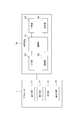
図13は、図9に示した生体センサ1、及び生体センサ1に接続される測定装置100の概略構成を示す機能ブロック図である。
図13に示すように、生体センサ1は、第1光源21と、第2光源22と、受光部23と、音出力部30とを備えている。これらの機能部については、既に説明したため、より詳細な説明は省略する。
図13に示すように、生体センサ1は、外部機器である測定装置100に接続されてよい。この場合、生体センサ1は、測定装置100に、ケーブル14を介して接続されてもよい。生体センサ1は、図13に示される測定装置100の全て、若しくは少なくとも一部を生体センサ1の内部に一体的に有するとしてもよい。
図13に示すように、測定装置100は、制御部101と、記憶部103と、通信部105と、入力部107と、表示部109とを備えてよい。測定装置100は、生体センサ1に接続可能な任意の外部機器としてよい。例えば、測定装置100は、生体センサ1に接続されるための専用端末としてよい。また、測定装置100は、例えば、スマートフォン、タブレット端末、ノートパソコン、又は汎用のパソコンなど、既存の任意の電子機器としてもよい。この場合、これらの電子機器には、生体センサ1によって被験者の生体情報を測定したり、測定した生体情報に基づいて被検者の状態を推定したりするためのアプリケーションソフトウェアを起動させてもよい。生体センサ1は、内部のバッテリ又は外部電源から電力が供給されるとしてもよい。
制御部101は、生体センサ1及び測定装置100の少なくとも一方の各機能ブロックをはじめとして、生体センサ1及び測定装置100の少なくとも一方の全体を制御及び管理する。制御部101は、例えば少なくとも1つのプロセッサを含んで構成されてよい。制御部101は、制御手順を規定したプログラムを実行するCPU(Central Processing Unit)等の少なくとも1つのプロセッサを含んで構成され、その機能を実現する。このようなプログラムは、例えば記憶部103、又は測定装置100に接続された外部の記憶媒体等に格納されてよい。
種々の実施形態によれば、少なくとも1つのプロセッサは、単一の集積回路(IC)として、又は複数の通信可能に接続された集積回路IC及び/又はディスクリート回路(discrete circuits)として実行されてもよい。少なくとも1つのプロセッサは、種々の既知の技術に従って構成されることが可能である。
一実施形態において、プロセッサは、例えば、関連するメモリに記憶された指示を実行することによって1以上のデータ計算手続又は処理を実行するように構成された1以上の回路又はユニットを含む。他の実施形態において、プロセッサは、1以上のデータ計算手続き又は処理を実行するように構成されたファームウェア(例えば、ディスクリートロジックコンポーネント)であってもよい。
種々の実施形態によれば、プロセッサは、1以上のプロセッサ、コントローラ、マイクロプロセッサ、マイクロコントローラ、特定用途向け集積回路(ASIC)、デジタル信号処理装置、プログラマブルロジックデバイス、フィールドプログラマブルゲートアレイ、又はこれらのデバイス若しくは構成の任意の組み合わせ、又は他の既知のデバイス若しくは構成の組み合わせを含み、以下に説明される制御部101としての機能を実行してもよい。
制御部101は、例えば、生体情報の測定処理を制御する。例えば、制御部101は、生体センサ1による被検者のSpO2の測定処理を制御する。制御部101は、測定した情報に基づいて、被検者の状態を推定してよい。本実施形態では、例えば、制御部101は、測定した被検者のSpO2に基づいて、被検者が高山病(高度障害ともいう)になる可能性を推定してもよい。高山病は、SpO2が低下することにより発症しやすくなる。
制御部101は、測定した生体情報及び/又は推定した高山病になる可能性に関する情報を、音出力部30を制御することにより、音出力部30を介して被検者に報知してよい。また、制御部101は、このような情報を、表示部109を制御することにより、表示部109を介して被検者に報知してよい。これにより、被検者は、報知された情報を知ることができる。例えば、被検者は、高山病になる可能性が高い旨の報知を受けた場合、高山病を防止する対策を事前に講じることができる。
記憶部103は、半導体メモリ又は磁気メモリ等で構成されることができる。記憶部103は、各種情報又は測定装置100を動作させるためのプログラム等を記憶する。記憶部103は、ワークメモリとしても機能してもよい。記憶部103は、例えば、制御部101が算出した被検者の体温及びSpO2を、履歴情報として記憶してよい。記憶部103は、制御部101が推定した高山病になる可能性に関する情報を、記憶してもよい。
一実施形態において、記憶部103は、音出力部160が出力する音の情報を記憶してもよい。ここで、記憶部103が記憶する音の情報とは、例えばMP3(MPEG-1 Audio Layer-3)ファイル又はWAVファイルのような、任意の形式の音声ファイルであってよい。一実施形態において、記憶部103は、測定装置100を使用している被検者の状態に応じて、各種の音の情報を記憶してもよい。
通信部105は、例えば生体センサ1又は外部サーバのような外部機器と有線通信又は無線通信を行うことにより、各種データの送受信を行う。通信部304は、無線、有線、又は無線と有線との組合せによるネットワークを用いて情報の送受信を行うことができる。通信部105は、例えばBluetooth(登録商標)、赤外線、NFC、無線LAN、有線LAN若しくはその他任意の通信媒体又はこれらの任意の組み合わせにより通信を行うことができる。
通信部105は、例えば、健康状態を管理するために被検者の生体情報を記憶する外部装置と通信を行ってもよい。この場合、通信部105は、生体センサ1が測定した結果、及び/又は測定装置100が推定した健康状態を、当該外部装置に送信してもよい。また、測定装置100が生体センサ1とケーブル14を介して接続される場合、通信部105は、例えばケーブル14を接続するインタフェースとしてもよい。
入力部107は、キーボード等の物理キーを含んで構成されてよいし、タッチパネルを含んで構成されてよい。入力部107は、これらに限られず、種々の入力デバイスを含んで構成されてよい。一実施形態において、測定装置100は、入力部107に対する操作者の操作入力に基づいて、生体センサ1が被検者の生体情報を測定することに関する制御を開始してもよい。
表示部109は、文字又は画像等で情報を報知する。表示部109は、液晶ディスプレイ(LCD:Liquid Crystal Display)、有機ELディスプレイ(OELD:Organic Electro-Luminescence Display)、又は無機ELディスプレイ(IELD:Inorganic Electro-Luminescence Display)等の表示デバイスとしてもよい。一実施形態において、表示部109は、生体センサ1が測定した被検者の生体情報、及び/又は当該生体情報に基づく各種情報を表示してもよい。これにより、被検者又は検査者は、被検者の生体情報、及び/又は当該生体情報に基づく各種情報を認識することができる。一実施形態において、表示部109は、音出力部30から出力する情報を、文字又は画像等の情報として表示してもよい。
図14は、測定装置100が実行する動作を示すフローチャートである。測定装置100は、例えば、被検者が測定装置100に接続された生体センサ1を耳に装着して、測定処理を実行させるための入力操作を入力部107に対して行ったとき、図14に示す動作を開始してよい。
図14に示す処理が開始すると、測定装置100の制御部101は、生体情報を測定する(ステップS1)。具体的には、測定装置100は、生体センサ1の測定部20により被検者の耳輪部分における生体情報を測定する。ここで、生体センサ1の測定部20が測定する生体情報は、例えば被検者のSpO2としてよい。生体センサ1の測定部20によって測定されたSpO2に関する情報は、測定装置100の制御部101に送信される。一実施形態に係る測定装置100は、ステップS1において、生体センサ1の測定部20による測定の結果を、例えば記憶部103に記憶してもよい。
測定装置100の制御部101は、測定された生体情報に基づき、被検者の状態を推定する(ステップS2)。具体的には、制御部101は、例えば、被検者のSpO2に基づき、被検者が高山病になる可能性を推定してよい。
ステップS2において、一実施形態に係る測定装置100の制御部101は、生体センサ1の測定部20が測定した情報に基づいて、被検者の状態を推定してもよい。例えば、制御部101は、被検者のSpO2がいずれも所定の閾値を超えるなど所定の条件を満たしたら、被検者が高山病になる可能性が高いと推定してもよい。また、例えば、制御部101は、被検者のSpO2が所定の範囲内にある場合、被検者が所定の健康状態にあると推定してもよい。
制御部101は、音出力部30に制御信号を送信することにより、音出力部30を介して被検者に情報を報知する(ステップS3)。例えば、制御部101は、被検者に所定の音又は音声を聞かせることにより、情報を報知してよい。
測定装置100は、ステップS1乃至ステップS3を定期的、不定期的、又は継続的に、繰り返し実行してもよい。これにより、測定装置100は、被検者の生体情報及び被検者の状態の履歴を連続的に取得することができる。
測定装置100は、ステップS3において、音出力部30以外の他の手段により、情報を報知してもよい。例えば、測定装置100は、表示部109に情報を表示することにより、情報を報知してもよい。また、測定装置100は、被検者が認識可能な、他の任意の手段により情報を報知してもよい。
このように、一実施形態に係る生体センサ1は、測定部20が測定した被検者の経皮的動脈血酸素飽和度(SpO2)及び血流量の少なくとも一方に基づく情報を、音出力部30から音及び音声の少なくとも一方として出力してもよい。
次に、他の実施形態に係る生体センサについて説明する。
図13において説明した生体センサ1は、被検者の生体情報を測定する機能と、被検者の耳に音又は音声を出力する機能とを有するものとして説明した。すなわち、図13において説明した生体センサ1は生体情報を処理する機能を備えず、生体センサ1に接続された測定装置100が生体情報を処理するものとして説明した。
しかしながら、他の実施形態に係る生体センサは、例えば生体情報を処理する機能を自ら備えてもよい。以下、このような実施形態について説明する。
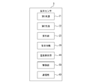
図15は、他の実施形態に係る生体センサの概略構成を示す機能ブロック図である。図15に示すように、他の実施形態に係る生体センサ3は、第1光源21と、第2光源22と、受光部23と、音出力部30と、温度検出部40と、制御部50と、通信部60とを備えている。第1光源21、第2光源22、受光部23、及び音出力部30については、既に説明したため、より詳細な説明は省略する。
生体センサ3は、図15に示すように、温度検出部40を備えてもよい。温度検出部40は、例えばサーミスタなど、接触する部位の温度を検出することができる任意の温度センサとしてよい。温度検出部40は、本体部10において、被検者の体温を検出可能な任意の位置に配置されてよい。例えば、温度検出部40は、第1装着部10a及び第2装着部10bの少なくとも一方において、測定部20の近傍に配置されてもよい。このように配置することで、温度検出部40は、被検者の耳輪部分における温度、すなわち被検者の体温を検出することができる。
生体センサ3は、温度検出部40が検出する被検者の体温の情報を、例えば音出力部30から音又は音声として出力してもよい。また、生体センサ3は、被検者の状態を推定する際に、温度検出部40が検出する被検者の体温を考慮してもよい。
制御部50は、図13に示した測定装置100の制御部101と同様の機能を実行する機能部としてよい。生体センサ3は、このような制御部50を、本体部10の任意の箇所に内蔵してもよい。例えば、本体部10の第2装着部10bを、第1装着部10aよりも大きなサイズで形成して、小型の制御部50を内蔵してもよい。
このように、一実施形態に係る生体センサ3は、測定部20が測定した被検者の経皮的動脈血酸素飽和度(SpO2)及び血流量の少なくとも一方の情報に所定の処理を行う制御部50を備えてもよい。生体センサ3は、制御部50を備えることにより、図13に示した測定装置100のような外部機器に接続することなく、測定部20が測定する被検者の生体情報に基づいて被検者の状態を推定することができる。すなわち、生体センサ3は、外部機器に接続することなく、単独で完結した機能を実行することができる。また、一実施形態に係る生体センサ3は、測定部20が測定した被検者の経皮的動脈血酸素飽和度(SpO2)及び血流量の少なくとも一方に基づく情報を、音出力部30から音及び音声の少なくとも一方として出力してもよい。
通信部60は、図13に示した測定装置100の通信部105と同様の機能を実行する機能部としてよい。一実施形態に係る生体センサ3は、生体センサ1が測定した結果、及び/又は制御部50が推定した健康状態を、例えば外部サーバのような外部機器に送信してもよい。このように、一実施形態に係る生体センサ3は、外部の端末機器に有線又は無線で接続する通信部60を備えてもよい。また、生体センサ1が外部機器とケーブル14を介して接続される場合、通信部60は、例えばケーブル14を接続するインタフェースとしてもよい。
以上説明したように、一実施形態に係る生体センサによれば、被検者の生体情報を測定する際に、被検者に課される心身の負担を軽減しつつ、安定して生体情報を測定することができる。したがって、一実施形態に係る生体センサによれば、利便性を向上させることができる。
一実施形態に係る生体センサは、被検者の耳に装着されることで、耳たぶに光を照射して被験者の生体情報を測定する場合とほぼ同等の光度によって測定を行うことができる。したがって、一実施形態に係る生体センサによれば、例えば被験者の指先などに光を照射して測定する場合に比べて少ない光度で測定することができる。このため、一実施形態に係る生体センサによれば、従来の一般的な測定機器よりも、低消費電力を実現することができる。
また、一実施形態に係る生体センサは、被検者に無理な姿勢又は体勢を強いることなく、被検者の自然な状態において、被検者に違和感を与えずに、生体情報の測定を可能にする。したがって、一実施形態に係る生体センサは、被検者の疲労感などの負担を最小限にすることができる。また、一実施形態に係る生体センサはウェアラブルに構成されているため、例えば被験者が運動中などのように動いていても使用することができる。また、一実施形態に係る生体センサによれば、被検者の耳輪部分に安定して位置付けられるため、被検者の生体情報の測定も安定させることができる。
本開示に係る実施形態について、諸図面及び実施例に基づき説明してきたが、当業者であれば本開示に基づき種々の変形又は修正を行うことが容易であることに注意されたい。従って、これらの変形又は修正は本開示の範囲に含まれることに留意されたい。例えば、各構成部又は各ステップなどに含まれる機能などは論理的に矛盾しないように再配置可能であり、複数の構成部又はステップなどを1つに組み合わせたり、或いは分割したりすることが可能である。本開示に係る実施形態について装置を中心に説明してきたが、本開示に係る実施形態は装置の各構成部が実行するステップを含む方法としても実現し得るものである。本開示に係る実施形態は装置が備えるプロセッサにより実行される方法、プログラム、又はプログラムを記録した記憶媒体としても実現し得るものである。本開示の範囲にはこれらも包含されるものと理解されたい。本開示を諸図面及び実施例に基づき説明してきたが、当業者であれば、本開示に基づき種々の変形又は修正を行うことが容易であることに注意されたい。したがって、これらの変形又は修正は、本開示の範囲に含まれることに留意されたい。例えば、各機能部に含まれる機能などは、論理的に矛盾しないように再配置可能である。複数の機能部等は、1つに組み合わせられたり、分割されたりしてよい。上述した本開示に係る各実施形態は、それぞれ説明した各実施形態に忠実に実施することに限定されるものではなく、適宜、各特徴を組み合わせたり、一部を省略したりして実施され得る。つまり、本開示の内容は、当業者であれば、本開示に基づき種々の変形および修正を行うことができる。したがって、これらの変形及び修正は本開示の範囲に含まれる。例えば、各実施形態において、各機能部、各手段、各ステップなどは、論理的に矛盾しないように他の実施形態に追加し、若しくは、他の実施形態の各機能部、各手段、各ステップなどと置き換えることが可能である。また、各実施形態において、複数の各機能部、各手段、各ステップなどを1つに組み合わせたり、或いは分割したりすることが可能である。また、上述した本開示の各実施形態は、それぞれ説明した各実施形態に忠実に実施することに限定されるものではなく、適宜、各特徴を組み合わせたり、一部を省略したりして実施することもできる。
1,1’,2,2’ 生体センサ
10 本体部
10a 第1装着部
10b 第2装着部
10c 結合部
12 音出力孔
14 ケーブル
16 ケーブル接続部
21 第1光源
22 第2光源
23 受光部
30 音出力部
40 温度検出部
50 制御部
60 通信部
100 測定装置
101 制御部
103 記憶部
105 通信部
107 入力部
109 表示部
10 本体部
10a 第1装着部
10b 第2装着部
10c 結合部
12 音出力孔
14 ケーブル
16 ケーブル接続部
21 第1光源
22 第2光源
23 受光部
30 音出力部
40 温度検出部
50 制御部
60 通信部
100 測定装置
101 制御部
103 記憶部
105 通信部
107 入力部
109 表示部
Claims (15)
- 第1装着部及び第2装着部によって被検者の耳輪部分を挟むように構成される本体部と、
被検者の経皮的動脈血酸素飽和度(SpO2)及び血流量の少なくとも一方を測定する測定部と、
を備える生体センサ。 - 前記本体部は、前記第1装着部と前記第2装着部とを結合する結合部を備える、請求項1に記載の生体センサ。
- 前記結合部は、前記第1装着部と前記第2装着部とを互いに対して変位可能に結合する、請求項2に記載の生体センサ。
- 前記本体部は、前記第1装着部、前記第2装着部、及び前記結合部の少なくともいずれかの弾性によって、前記被検者の耳輪部分を挟むように構成される、請求項2又は3に記載の生体センサ。
- 前記測定部は、前記第1装着部及び前記第2装着部の少なくとも一方に配置される、請求項1から4のいずれかに記載の生体センサ。
- 前記測定部は、発光部及び受光部を備えている、請求項1から5のいずれかに記載の生体センサ。
- 前記発光部は前記第1装着部及び前記第2装着部の一方に配置され、前記受光部は前記第1装着部及び前記第2装着部の他方に配置される、請求項6に記載の生体センサ。
- 前記発光部及び前記受光部の双方は、前記第1装着部及び前記第2装着部の一方に配置される、請求項6に記載の生体センサ。
- 前記発光部は、第1光源及び第2光源を備えている、請求項6から8のいずれかに記載の生体センサ。
- 前記第1装着部の端部は前記被検者の外耳道に挿入され、
前記第1装着部は、前記第1装着部の前記端部から音を出力する音出力部を備える、請求項1から9のいずれかに記載の生体センサ。 - 前記第1装着部の端部は前記被検者の外耳道の入口手前に位置付けられ、
前記第1装着部は、前記第1装着部の前記端部から音を出力する音出力部を備える、請求項1から9のいずれかに記載の生体センサ。 - 前記音出力部は、空気振動及び骨伝導の少なくとも一方によって音を伝達する、請求項10又は11に記載の生体センサ。
- 前記測定部が測定した前記被検者の経皮的動脈血酸素飽和度(SpO2)及び血流量の少なくとも一方に基づく情報を、前記音出力部から音及び音声の少なくとも一方として出力する、請求項10から12のいずれかに記載の生体センサ。
- 前記測定部が測定した前記被検者の経皮的動脈血酸素飽和度(SpO2)及び血流量の少なくとも一方の情報に所定の処理を行う制御部を備える、請求項1から13のいずれかに記載の生体センサ。
- 外部の端末機器に有線又は無線で接続する通信部を備える、請求項1から14のいずれかに記載の生体センサ。
Priority Applications (2)
| Application Number | Priority Date | Filing Date | Title |
|---|---|---|---|
| US17/290,871 US20210267464A1 (en) | 2018-11-15 | 2019-11-06 | Biosensor |
| JP2020556109A JP7244539B2 (ja) | 2018-11-15 | 2019-11-06 | 生体センサ |
Applications Claiming Priority (2)
| Application Number | Priority Date | Filing Date | Title |
|---|---|---|---|
| JP2018214807 | 2018-11-15 | ||
| JP2018-214807 | 2018-11-15 |
Publications (1)
| Publication Number | Publication Date |
|---|---|
| WO2020100677A1 true WO2020100677A1 (ja) | 2020-05-22 |
Family
ID=70731355
Family Applications (1)
| Application Number | Title | Priority Date | Filing Date |
|---|---|---|---|
| PCT/JP2019/043424 Ceased WO2020100677A1 (ja) | 2018-11-15 | 2019-11-06 | 生体センサ |
Country Status (3)
| Country | Link |
|---|---|
| US (1) | US20210267464A1 (ja) |
| JP (1) | JP7244539B2 (ja) |
| WO (1) | WO2020100677A1 (ja) |
Cited By (1)
| Publication number | Priority date | Publication date | Assignee | Title |
|---|---|---|---|---|
| JP2022156617A (ja) * | 2021-03-31 | 2022-10-14 | クレプシードラ株式会社 | 音響装置 |
Families Citing this family (2)
| Publication number | Priority date | Publication date | Assignee | Title |
|---|---|---|---|---|
| JP6900432B2 (ja) * | 2019-08-08 | 2021-07-07 | 京セラ株式会社 | 電子機器、制御方法、及び制御プログラム |
| EP4309573A1 (en) * | 2022-07-21 | 2024-01-24 | Sonion Nederland B.V. | Determination of a parameter related to blood flow in a blood perfused part using a vcsel |
Citations (4)
| Publication number | Priority date | Publication date | Assignee | Title |
|---|---|---|---|---|
| JP2006102264A (ja) * | 2004-10-06 | 2006-04-20 | Terumo Corp | 血圧監視装置および血圧監視方法 |
| WO2013161729A1 (ja) * | 2012-04-25 | 2013-10-31 | 株式会社村田製作所 | 心電信号計測装置、及び、心電信号計測方法 |
| JP2014068835A (ja) * | 2012-09-28 | 2014-04-21 | Bifristec Kk | 検体情報検出装置及び検体情報処理装置並びに検体情報検出方法及び検体情報を検出するための装置 |
| JP2017038911A (ja) * | 2015-03-16 | 2017-02-23 | 和弘 谷口 | 耳装着型装置 |
Family Cites Families (9)
| Publication number | Priority date | Publication date | Assignee | Title |
|---|---|---|---|---|
| US8073518B2 (en) * | 2006-05-02 | 2011-12-06 | Nellcor Puritan Bennett Llc | Clip-style medical sensor and technique for using the same |
| JP2008168051A (ja) | 2007-01-15 | 2008-07-24 | Citizen Holdings Co Ltd | 心拍計 |
| US8655005B2 (en) * | 2009-06-09 | 2014-02-18 | Gn Netcom A/S | Earphone system comprising an earphone and a portable holding device |
| US8532729B2 (en) * | 2011-03-31 | 2013-09-10 | Covidien Lp | Moldable ear sensor |
| US9185501B2 (en) * | 2012-06-20 | 2015-11-10 | Broadcom Corporation | Container-located information transfer module |
| US20170049335A1 (en) * | 2015-08-19 | 2017-02-23 | Logitech Europe, S.A. | Earphones with biometric sensors |
| US10098576B2 (en) * | 2014-03-14 | 2018-10-16 | Covidien Lp | Regional saturation shock detection method and system |
| US10063958B2 (en) * | 2014-11-07 | 2018-08-28 | Microsoft Technology Licensing, Llc | Earpiece attachment devices |
| US20160199001A1 (en) * | 2015-01-10 | 2016-07-14 | Cheng Uei Precision Industry Co., Ltd. | Heart rate detection earphone |
-
2019
- 2019-11-06 US US17/290,871 patent/US20210267464A1/en not_active Abandoned
- 2019-11-06 WO PCT/JP2019/043424 patent/WO2020100677A1/ja not_active Ceased
- 2019-11-06 JP JP2020556109A patent/JP7244539B2/ja active Active
Patent Citations (4)
| Publication number | Priority date | Publication date | Assignee | Title |
|---|---|---|---|---|
| JP2006102264A (ja) * | 2004-10-06 | 2006-04-20 | Terumo Corp | 血圧監視装置および血圧監視方法 |
| WO2013161729A1 (ja) * | 2012-04-25 | 2013-10-31 | 株式会社村田製作所 | 心電信号計測装置、及び、心電信号計測方法 |
| JP2014068835A (ja) * | 2012-09-28 | 2014-04-21 | Bifristec Kk | 検体情報検出装置及び検体情報処理装置並びに検体情報検出方法及び検体情報を検出するための装置 |
| JP2017038911A (ja) * | 2015-03-16 | 2017-02-23 | 和弘 谷口 | 耳装着型装置 |
Cited By (2)
| Publication number | Priority date | Publication date | Assignee | Title |
|---|---|---|---|---|
| JP2022156617A (ja) * | 2021-03-31 | 2022-10-14 | クレプシードラ株式会社 | 音響装置 |
| JP7681890B2 (ja) | 2021-03-31 | 2025-05-23 | クレプシードラ株式会社 | 音響装置 |
Also Published As
| Publication number | Publication date |
|---|---|
| US20210267464A1 (en) | 2021-09-02 |
| JPWO2020100677A1 (ja) | 2021-09-24 |
| JP7244539B2 (ja) | 2023-03-22 |
Similar Documents
| Publication | Publication Date | Title |
|---|---|---|
| US12220257B2 (en) | Nose sensor | |
| US11931176B2 (en) | Nose sensor | |
| US11272883B2 (en) | Physiological sensor | |
| US12279892B2 (en) | Methods and apparatus for detecting motion via optomechanics | |
| US20230363670A1 (en) | Ear-wearable oxygen monitoring system | |
| US20210174955A1 (en) | Noninvasive multi-parameter patient monitor | |
| US20170251974A1 (en) | Nose sensor | |
| JP7244539B2 (ja) | 生体センサ | |
| CN107111334A (zh) | 用于传达情感状态的模块化可穿戴设备 | |
| JP2009539576A (ja) | 構成変更可能なパルスオキシメーター | |
| CN118510447A (zh) | 使用可穿戴生物传感器测量血氧饱和度和生命体征的方法、装置和系统 | |
| WO2019244611A1 (ja) | 測定装置、測定方法、及び測定プログラム | |
| JP2019076692A (ja) | 測定装置及び測定システム | |
| WO2019082605A1 (ja) | 測定装置及び測定システム |
Legal Events
| Date | Code | Title | Description |
|---|---|---|---|
| 121 | Ep: the epo has been informed by wipo that ep was designated in this application |
Ref document number: 19884340 Country of ref document: EP Kind code of ref document: A1 |
|
| ENP | Entry into the national phase |
Ref document number: 2020556109 Country of ref document: JP Kind code of ref document: A |
|
| NENP | Non-entry into the national phase |
Ref country code: DE |
|
| 122 | Ep: pct application non-entry in european phase |
Ref document number: 19884340 Country of ref document: EP Kind code of ref document: A1 |