WO2020100675A1 - Rotor, and rotary electric machine provided with same - Google Patents
Rotor, and rotary electric machine provided with same Download PDFInfo
- Publication number
- WO2020100675A1 WO2020100675A1 PCT/JP2019/043394 JP2019043394W WO2020100675A1 WO 2020100675 A1 WO2020100675 A1 WO 2020100675A1 JP 2019043394 W JP2019043394 W JP 2019043394W WO 2020100675 A1 WO2020100675 A1 WO 2020100675A1
- Authority
- WO
- WIPO (PCT)
- Prior art keywords
- rib
- magnetic pole
- center line
- rotor
- ribs
- Prior art date
Links
Images


Classifications
-
- H—ELECTRICITY
- H02—GENERATION; CONVERSION OR DISTRIBUTION OF ELECTRIC POWER
- H02K—DYNAMO-ELECTRIC MACHINES
- H02K1/00—Details of the magnetic circuit
- H02K1/06—Details of the magnetic circuit characterised by the shape, form or construction
- H02K1/22—Rotating parts of the magnetic circuit
- H02K1/27—Rotor cores with permanent magnets
- H02K1/2706—Inner rotors
- H02K1/272—Inner rotors the magnetisation axis of the magnets being perpendicular to the rotor axis
- H02K1/274—Inner rotors the magnetisation axis of the magnets being perpendicular to the rotor axis the rotor consisting of two or more circumferentially positioned magnets
- H02K1/2753—Inner rotors the magnetisation axis of the magnets being perpendicular to the rotor axis the rotor consisting of two or more circumferentially positioned magnets the rotor consisting of magnets or groups of magnets arranged with alternating polarity
- H02K1/276—Magnets embedded in the magnetic core, e.g. interior permanent magnets [IPM]
- H02K1/2766—Magnets embedded in the magnetic core, e.g. interior permanent magnets [IPM] having a flux concentration effect
-
- H—ELECTRICITY
- H02—GENERATION; CONVERSION OR DISTRIBUTION OF ELECTRIC POWER
- H02K—DYNAMO-ELECTRIC MACHINES
- H02K1/00—Details of the magnetic circuit
- H02K1/06—Details of the magnetic circuit characterised by the shape, form or construction
- H02K1/22—Rotating parts of the magnetic circuit
- H02K1/27—Rotor cores with permanent magnets
- H02K1/2706—Inner rotors
- H02K1/272—Inner rotors the magnetisation axis of the magnets being perpendicular to the rotor axis
- H02K1/274—Inner rotors the magnetisation axis of the magnets being perpendicular to the rotor axis the rotor consisting of two or more circumferentially positioned magnets
- H02K1/2753—Inner rotors the magnetisation axis of the magnets being perpendicular to the rotor axis the rotor consisting of two or more circumferentially positioned magnets the rotor consisting of magnets or groups of magnets arranged with alternating polarity
- H02K1/276—Magnets embedded in the magnetic core, e.g. interior permanent magnets [IPM]
-
- H—ELECTRICITY
- H02—GENERATION; CONVERSION OR DISTRIBUTION OF ELECTRIC POWER
- H02K—DYNAMO-ELECTRIC MACHINES
- H02K21/00—Synchronous motors having permanent magnets; Synchronous generators having permanent magnets
- H02K21/12—Synchronous motors having permanent magnets; Synchronous generators having permanent magnets with stationary armatures and rotating magnets
- H02K21/14—Synchronous motors having permanent magnets; Synchronous generators having permanent magnets with stationary armatures and rotating magnets with magnets rotating within the armatures
-
- H—ELECTRICITY
- H02—GENERATION; CONVERSION OR DISTRIBUTION OF ELECTRIC POWER
- H02K—DYNAMO-ELECTRIC MACHINES
- H02K2213/00—Specific aspects, not otherwise provided for and not covered by codes H02K2201/00 - H02K2211/00
- H02K2213/03—Machines characterised by numerical values, ranges, mathematical expressions or similar information
Definitions
- the present disclosure relates to a rotor and a rotating electric machine including the rotor.
- a rotor including a core portion in which a through hole group including a plurality of through holes is formed is known (for example, Patent Document 1).
- the core portion of the rotor of the document has ribs located between the through holes, and the widths of the ribs are substantially equal to each other.
- the purpose of the present disclosure is to optimize the size of the ribs of the rotor.
- a first aspect of the present disclosure is a rotor including a core portion (21) in which a through hole group (100) including three or more through holes (25) arranged in the circumferential direction is formed in a predetermined magnetic pole (21). 20) is targeted.
- the rotor (20) is provided in the core portion (21) and includes two or more ribs (24) located between the through holes (25), and the center of the magnetic pole in the circumferential direction and the center of the magnetic pole in the circumferential direction.
- the rib (24) having a relatively small inclination ( ⁇ ) with respect to the magnetic pole center line (MC) is defined by a straight line passing through the shaft center (O) of the rotor (20).
- the width is narrower than that of the rib (24) having a relatively large inclination ( ⁇ ) with respect to the magnetic pole center line (MC).
- the inventor of the present application has found that, in a given magnetic pole, the centrifugal force acting on the radially outer portion of the through hole group (100) is substantially parallel to the magnetic pole center line (MC), and the rib (24) in the magnetic pole. And that as the inclination ( ⁇ ) of the rib (24) with respect to the magnetic pole center line becomes smaller, the bending force acting on the rib (24) due to the centrifugal force becomes smaller. It was Further, the inventor of the present application has found that the smaller the force in the bending direction acting on the rib (24), the less the problem of strength design even if the rib (24) is designed to be narrow.
- the rib (24) having a relatively small inclination ( ⁇ ) with respect to the magnetic pole center line (MC) has a relatively small inclination ( ⁇ ) with respect to the magnetic pole center line (MC).
- ⁇ inclination
- MC magnetic pole center line
- the “inclination” of the rib (24) with respect to the magnetic pole center line (MC) means the center line (CL) of the rib (24) (that is, the rib (24) as shown in FIG. ) Means the angle ( ⁇ ) formed between the magnetic pole center line (MC) and the straight line passing through the middle of the two through holes (25) adjacent to each other.
- the “width” of the rib (24) means the shortest length (W) of the rib (24). More specifically, the “width” of the rib (24) is, as shown in FIG.
- a straight center line (CL ) May be the shortest length (W) of the rib (24).
- a distance (L) from the magnetic pole center line (MC) in the circumferential direction is relatively small.
- the neighboring rib (24-1) includes a rib (24-1) and a spacing rib (24-2, 24-3) having a relatively large distance (L) from the magnetic pole center line (MC) in the circumferential direction.
- the inclination ( ⁇ 1) of (-1) with respect to the magnetic pole center line (MC) is smaller than the inclination ( ⁇ 2, ⁇ 3) of the separation ribs (24-2, 24-3) with respect to the magnetic pole center line (MC),
- the neighboring rib (24-1) is characterized in that it is narrower than the spacing ribs (24-2, 24-3).
- the neighboring rib (24-1) having a relatively small inclination ( ⁇ 1) with respect to the magnetic pole center line (MC) has a relatively large inclination ( ⁇ 2, ⁇ 3) with respect to the magnetic pole center line (MC). It is designed to be narrower than the large spacing ribs (24-2, 24-3).
- the neighboring ribs (24-1), which have a relatively small bending-direction force acting due to the centrifugal force have similar spacing-direction bending ribs (24-2, 24). -3) is designed to be narrower than.
- the “distance” from the magnetic pole center line (ML) in the circumferential direction means the center of the rib (24) in the longitudinal and width directions from the magnetic pole center line (ML) as shown in FIG. Means the circumferential distance (L) to.
- a portion of the through hole (25) adjacent to the rib (24) is a rib adjacent portion (25a), and the through hole (25).
- a rib chamfer is formed on the rib adjacent portion (25a), and the rib adjacent portion (25a) adjacent to the rib (24) has a relatively small inclination ( ⁇ ) with respect to the magnetic pole center line (MC).
- the R chamfer dimension (R) is the R chamfer dimension (R) of the rib adjacent portion (25a) adjacent to the rib (24) having a relatively large inclination ( ⁇ ) with respect to the magnetic pole center line (MC). It is characterized by being smaller than R).
- the rib (24) having a relatively small inclination ( ⁇ ) with respect to the magnetic pole center line (MC) is compared with the rib (24) having a relatively large inclination ( ⁇ ) with respect to the magnetic pole center line (MC).
- it is designed to be narrow over a wide range in the longitudinal direction, which is the direction along the center line (CL). This is because, of the ribs (24), the portion adjacent to the portion of the rib adjacent portion (25a) where the R chamfer is formed is wider than the other portions, whereas the former rib (24) is different from the latter rib (24). This is because the wider range becomes smaller than that in 24).
- the size of the former rib (24) on which a relatively small force in the bending direction acts can be further optimized.
- R chamfer means that the intersecting surface portion is rounded.
- the through hole group (100) includes four or more holes arranged substantially symmetrically with respect to the magnetic pole center line (MC).
- Two or more ribs (24) each including an even number of through holes (25) include a central rib (24-1) located on the magnetic pole center line (MC).
- the mass point of the radially outer portion of the through hole group (100) is located on the center line (CL) of the center rib (24-1) (that is, on the magnetic pole center line (MC)). .. Therefore, the force in the bending direction that acts on the central rib (24-1) due to the centrifugal force that acts on the mass point is extremely small. As a result, the width of the center rib (24-1) can be narrowed as compared with the case where the center rib (24-1) is provided at a position other than on the magnetic pole center line (MC). It is possible to suppress magnetic flux leakage (that is, generation of magnetic flux that does not contribute to torque generation) via 1).
- substantially symmetric means not only strictly symmetrical with respect to the magnetic pole center line (MC) but also slightly asymmetrical with respect to the magnetic pole center line (MC) due to manufacturing error. It is meant to include some cases.
- a fifth aspect of the present disclosure is the first aspect, wherein the two or more ribs (24) are parallel ribs (24-1) extending substantially parallel to the magnetic pole center line (MC).
- the parallel ribs (24-1) include the inclined ribs (24-2, 24-3) extending obliquely with respect to the magnetic pole center line (MC), and the parallel ribs (24-1) have the inclined ribs (24-2, 24-3). It is characterized by being narrower than -3).
- the inclination ( ⁇ 1) with respect to the magnetic pole center line (MC) is relatively small, and the parallel rib (24-1) having a very small inclination ( ⁇ 2, ⁇ 3) with respect to the magnetic pole center line (MC).
- substantially parallel means that the angle ( ⁇ ) formed by the magnetic pole center line (MC) and the center line (CL) of the rib (24) is less than 5 °.
- “Inclined” means that the angle ( ⁇ ) formed by the magnetic pole center line (MC) and the center line (CL) of the rib (24) is 5 ° or more.
- the direction in which the rib (24) “extends” means the direction in which the center line (CL) of the rib (24) extends.
- a sixth aspect of the present disclosure is the method according to any one of the first to fifth aspects, wherein a permanent magnet (26) is arranged in a part or all of the three or more through holes (25). It is characterized by being
- the magnetic flux of the permanent magnet (26) can be efficiently used. This is because the width dimension of the rib (24) is designed to be the minimum dimension required for strength design, and this causes the magnetic flux of the permanent magnet (26) to short-circuit in the rotor (20) via the rib (24). This is because it has become difficult.
- the seventh aspect of the present disclosure is directed to the rotating electric machine (1).
- This rotary electric machine (1) includes a rotor (20) according to any one of the first to sixth aspects, and a stator (10) provided outside the rotor (20) in the radial direction. ..
- the rotary electric machine (1) is an inner rotor type rotary electric machine. Since the ribs (24) of the rotor (20) included in the rotary electric machine (1) are designed to have necessary and sufficient dimensions in terms of strength design, high-speed rotation (for example, 10,000 to 15,000 rpm or more) ), The rotor (20) is less likely to be damaged due to centrifugal force.
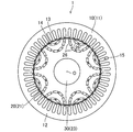
- FIG. 1 is a plan view showing the electric motor of the embodiment.
- FIG. 2 is a plan view showing a core member that constitutes the rotor.
- FIG. 3 is a partial plan view showing a through hole group corresponding to one magnetic pole in the rotor.
- FIG. 4 is a partial plan view showing a through hole group corresponding to one magnetic pole in a rotor of another embodiment.
- FIG. 5 is a schematic diagram for explaining dimensions and the like related to the through holes and the ribs.
- the electric motor (1) of the present embodiment is an example of a rotary electric machine, and is configured as an embedded magnet type electric motor.
- the configuration of the electric motor (1) will be described below.
- the electric motor (1) includes a stator (10), a rotor (20), and a drive shaft (30).
- the axial direction means the direction of the axis of the drive shaft (30)
- the radial direction means the direction orthogonal to the axial direction.
- the outer peripheral side means the side away from the axis, and the inner peripheral side means the side close to the axis.
- the stator (10) includes a cylindrical stator core (11) and a coil (not shown).
- the stator core (11) is configured by stacking a plurality of plate-shaped members formed by punching electromagnetic steel plates with a press machine in the axial direction. That is, the stator core (11) is a so-called laminated core.
- the stator core (11) may be composed of, for example, a dust core.
- the stator core (11) includes one back yoke part (12), a plurality of teeth (13), and the same number of brim parts (14) as the teeth (13).
- the back yoke part (12) is an annular part on the outer peripheral side of the stator core (11) in plan view.
- Each tooth (13) is a rectangular parallelepiped portion that extends in the radial direction in the stator core (11).
- the coil is wound around each tooth (13) by, for example, a distributed winding method.
- the space between the teeth (13) adjacent to each other functions as a coil slot (15) for housing the coil.
- the electromagnet is formed in each tooth (13).
- the coil may be wound around the tooth (13) by a concentrated winding method.
- the brim part (14) is a part that continuously extends to the inner peripheral side of each tooth (13) on both sides. Therefore, the flange portion (14) is formed to have a width (circumferential length) larger than that of the tooth (13).
- the flange portion (14) has a cylindrical surface on the inner peripheral side, and the cylindrical surface faces the outer peripheral surface (cylindrical surface) of the rotor (20) with a predetermined distance (air gap).
- the rotor (20) includes a rotor core (21) and a plurality of permanent magnets (26). In the rotor (20), these permanent magnets (26) form eight magnetic poles. All of these permanent magnets (26) have the same shape. These permanent magnets (26) are composed of, for example, sintered magnets.
- the permanent magnet (26) of this example is a so-called rare earth magnet using a rare earth element.
- the permanent magnet (26) penetrates the rotor core (21) in the axial direction.
- the rotor core (21) constitutes a core part.
- the rotor core (21) is a cylinder formed by stacking a large number of core members (22) in the axial direction by punching electromagnetic steel sheets with a thickness of 0.1 to 0.5 mm by a press machine. It is configured in a shape. That is, the rotor core (21) is a so-called laminated core.
- the rotor core (21) may be made of, for example, a high-strength electromagnetic steel plate, a silicon steel plate with a silicon content of 6.5%, or a dust core.
- the rotor core (21) has a shaft hole (23) formed in the center.
- a drive shaft (30) for driving a load (for example, a rotary compressor of an air conditioner) is fixed to the shaft hole (23) by interference fitting (for example, shrink fitting). Therefore, the axis (O) of the rotor core (21) (that is, the axis (O) of the rotor (20)) and the axis of the drive shaft (30) are coaxial with each other.
- each through hole (25) is determined so that a gap can be formed if necessary when the permanent magnet (26) is inserted.
- a through hole group (100) including a plurality of through holes (25) arranged in the circumferential direction for each magnetic pole is provided in the radial direction in a multilayer ( In the example, two layers are formed.
- the through hole group (100) of each layer is arranged along an arcuate region that is convex toward the axis (O) of the rotor (20).
- a branch number is added to the end of the reference numeral (for example, 25-1, 25-2, 100-1 etc.).
- one magnetic pole has two through hole groups (100).
- the through hole group (100-2) of the outer peripheral layer is formed by two through holes (25-5, 25-6).
- the through hole group (100-1) of the inner layer is formed by four through holes (25-1, 25-2, 25-3, 25-4).
- the four through holes (25-1, 25-2, 25-3, 25-4) forming the through hole group (100-1) of the inner peripheral layer are formed by the center of the magnetic pole in the circumferential direction and the rotor ( A straight line passing through the axis (O) of 20) is set as a magnetic pole center line (MC), and the magnetic pole center line (MC) is symmetrically arranged.
- ribs (24) are formed between two through holes (25) facing each other in each through hole group (100).
- the width of each rib (24) is as narrow as possible from the viewpoint of reducing magnetic flux leakage (that is, generation of magnetic flux that does not contribute to torque generation) in the rib (24).
- the width of each rib (24) is as wide as possible from the viewpoint of ensuring the strength capable of withstanding the centrifugal force acting on the rotor core (21) during operation of the electric motor (1).
- the ribs (24) are made as narrow as possible, and the ribs (24) are designed so that the ribs (24) can have sufficient strength. This point will be described below.
- the four through holes 25-1, There are ribs (24-1, 24-2, 24-3) between the (25-2, 25-3, 25-4). These three ribs (24-1, 24-2, 24-3) include one central rib (24-1) and two spacing ribs (24-2, 24-3).
- the center rib (24-1) is located on the magnetic pole center line (MC).
- the center rib (24-1) extends parallel to the magnetic pole center line (MC).
- the center rib (24-1) is narrower than the spacing ribs (24-2, 24-3).
- the width of the central rib (24-1) is preferably about 1/2 to 1/5 of the width of the spacing ribs (24-2, 24-3).
- the center rib (24-1) of the core member (22) having an outer diameter of 128 mm has a width of about 0.5 to 1.5 mm
- the separation ribs (24-2, 24-3) have a width of 1.5 to 5 mm. It is desirable to be about 0.0 mm.
- the width of the central rib (24-1) is preferably twice the thickness of the core member (22) or more.
- the center rib (24-1) constitutes a rib having a relatively small inclination ( ⁇ 1) (that is, substantially 0 °) with respect to the magnetic pole center line (MC) and constitutes a parallel rib.
- the center rib (24-1) constitutes a neighboring rib.
- Each separation rib (24-2, 24-3) is located apart from the magnetic pole center line (MC). In other words, the distances (L2, L3) from the magnetic pole center line (MC) in the circumferential direction of the respective separation ribs (24-2, 24-3) are the same as the distance (L1) in the center rib (24-1). Greater than (ie, substantially zero).
- the two separating ribs (24-2, 24-3) are symmetrical with respect to the magnetic pole center line (MC).
- Each of the spacing ribs (24-3, 24-3) extends obliquely with respect to the magnetic pole center line (MC).
- the inclinations ( ⁇ 2, ⁇ 3) of the spacing ribs (24-2, 24-3) with respect to the magnetic pole center line (MC) are larger than the similar inclinations ( ⁇ 1) of the center rib (24-1).
- the separation ribs (24-2, 24-3) form a rib having a relatively large inclination ( ⁇ 2, ⁇ 3) with respect to the magnetic pole center line (MC) and also an inclined rib.
- the portion of each through hole (25) adjacent to the rib (24) is defined as a rib adjacent portion (25a).
- An R chamfer is formed in the rib adjacent portion (25a) of the hole (25).
- the R chamfer dimension (R1) of the central rib (24-1) is smaller than the R chamfer dimension (R2, R3) of the spacing ribs (24-2, 24-3).
- the rib (24-4 is provided between the two through holes (25-5, 25-6) forming the through hole group (100-2). ) Exists.
- the rib (24-4) is located on the magnetic pole center line (MC).
- the rib (24-4) is preferably narrower than the central rib (24-1).
- the width of the rib (24-4) is preferably twice the thickness of the core member (22) or more.
- each electromagnetic steel plate may satisfy the above configuration. The same effect can be obtained.
- the rotor (20) of the present embodiment includes a rotor core (21) in which a through hole group (100-1) composed of four through holes (25) arranged in the circumferential direction is formed on all magnetic poles.
- the rotor core (21) is provided with three ribs (24) located between the through holes (25), and the center of the magnetic pole in the circumferential direction and the axial center of the rotor (20) (
- the straight line passing through (O) and the magnetic pole center line (MC) is used, and the rib (24) having a relatively small inclination ( ⁇ ) with respect to the magnetic pole center line (MC) is inclined with respect to the magnetic pole center line (MC). It is narrower than the rib (24) having a relatively large ( ⁇ ).
- the inventor of the present application has found that, in a given magnetic pole, the centrifugal force acting on the radially outer portion of the through hole group (100) is substantially parallel to the magnetic pole center line (MC), and the rib (24) in the magnetic pole. And that as the inclination ( ⁇ ) of the rib (24) with respect to the magnetic pole center line becomes smaller, the bending force acting on the rib (24) due to the centrifugal force becomes smaller. It was Further, the inventor of the present application has found that the smaller the force in the bending direction acting on the rib (24), the less the problem of strength design even if the rib (24) is designed to be narrow.
- the rib (24) having a relatively small inclination ( ⁇ ) with respect to the magnetic pole center line (MC) has a relatively large inclination ( ⁇ ) with respect to the magnetic pole center line (MC).
- ⁇ inclination
- MC magnetic pole center line
- each rib (24) of the rotor (20) can be minimized, and thus the magnetic characteristics of the rotor (20) can be improved. This is because the wider the rib (24) is, the more the magnetic flux leaks through the rib (24) (that is, the generation of the magnetic flux that does not contribute to the torque generation) is suppressed. is there.
- both the strength design and the magnetic design can be optimized for the ribs (24) of the rotor (20).
- the three ribs (24) have neighboring ribs (24-1) whose distance (L) from the magnetic pole center line (MC) in the circumferential direction is relatively small.
- a spacing rib (24-2, 24-3) having a relatively large distance (L) from the magnetic pole center line (MC) in the circumferential direction, and the distance between the neighboring rib (24-1)
- the inclination ( ⁇ 1) with respect to the magnetic pole center line (MC) is smaller than the inclination ( ⁇ 2, ⁇ 3) of the separation ribs (24-2, 24-3) with respect to the magnetic pole center line (MC), and the neighboring ribs (24- 1) is narrower than the spacing ribs (24-2, 24-3).
- the neighboring rib (24-1) having a relatively small inclination ( ⁇ 1) with respect to the magnetic pole center line (MC) has a relatively large inclination ( ⁇ 2, ⁇ 3) with respect to the magnetic pole center line (MC). It is designed to be narrower than 24-2, 24-3).
- the neighboring ribs (24-1), which have a relatively small bending-direction force acting due to the centrifugal force have similar spacing-direction bending ribs (24-2, 24). -3) is designed to be narrower than.
- the sizes of the neighboring ribs (24-1) and the spacing ribs (24-2, 24-3) can be optimized to be necessary and sufficient.
- a portion of the through hole (25) adjacent to the rib (24) is defined as a rib adjacent portion (25a), and the rib adjacent portion of each of the through holes (25).
- the R chamfer is formed on the (25a), and the dimension of the R chamfer on the rib adjacent portion (25a) adjacent to the rib (24) having a relatively small inclination ( ⁇ ) with respect to the magnetic pole center line (MC).
- (R) is smaller than the dimension (R) of the R chamfer of the rib adjacent portion (25a) adjacent to the rib (24) having a relatively large inclination ( ⁇ ) with respect to the magnetic pole center line (MC).
- the rib (24) having a relatively small inclination ( ⁇ ) with respect to the magnetic pole center line (MC) has a width larger than that of the rib (24) having a relatively large inclination ( ⁇ ) with respect to the magnetic pole center line (MC).
- it is designed to be narrow over a wide range in the longitudinal direction, which is the direction along the center line (CL). This is because, of the ribs (24), the portion adjacent to the portion of the rib adjacent portion (25a) where the R chamfer is formed is wider than the other portions, whereas the former rib (24) is different from the latter rib (24). This is because the wider range becomes smaller than that in 24).
- the size of the former rib (24) on which a relatively small force in the bending direction acts can be further optimized.
- the through hole group (100) includes the four through holes (25) arranged substantially symmetrically with respect to the magnetic pole center line (MC), and the three through holes (25).
- the rib (24) includes a central rib (24-1) located on the magnetic pole center line (MC). Therefore, the mass point of the radially outer portion of the through hole group (100) is located on the center line (CL) of the center rib (24-1) (that is, on the magnetic pole center line (MC)). Therefore, the force in the bending direction that acts on the central rib (24-1) due to the centrifugal force that acts on the mass point is extremely small.
- the width of the center rib (24-1) can be narrowed as compared with the case where the center rib (24-1) is provided at a position other than on the magnetic pole center line (MC). Magnetic flux leakage via 1) can be suppressed.
- the three ribs (24) include parallel ribs (24-1) extending substantially parallel to the magnetic pole center line (MC) and the magnetic pole center line ( MC) and the inclined ribs (24-2, 24-3) extending obliquely with respect to the parallel ribs (24-1) are larger than the inclined ribs (24-2, 24-3). It is narrow. Therefore, the inclination ( ⁇ 1) relative to the magnetic pole center line (MC) is relatively small, and the inclination ( ⁇ 2, ⁇ 3) relative to the magnetic pole center line (MC) is relatively small for the parallel rib (24-1). It is designed to be narrower than the large inclined ribs (24-2, 24-3).
- the parallel rib (24-1) has a smaller force in the bending direction acting due to the centrifugal force than the inclined rib (24-2, 24-3). With such a dimensional design, it is possible to optimize the dimensions of the parallel ribs (24-1) and the inclined ribs (24-2, 24-3) to be necessary and sufficient.
- the permanent magnets (26) are arranged in all of the four through holes (25). Therefore, the magnetic flux of the permanent magnet (26) can be efficiently used. This is because the width dimension of the rib (24) is designed to be the minimum required dimension in terms of strength design, which causes the magnetic flux of the permanent magnet (26) to short-circuit in the rotor (20) via the rib (24). This is because it has become difficult.
- the electric motor (1) of the present embodiment includes the rotor (20) of the present embodiment and a stator (10) provided outside the rotor (20) in the radial direction. Therefore, the electric motor (1) is an inner rotor type electric motor. Since the ribs (24) of the rotor (20) included in the electric motor (1) are designed to have necessary and sufficient dimensions in terms of strength design, high-speed rotation (for example, 10,000 to 15,000 rpm or more) The rotor (20) is less likely to be damaged by centrifugal force even when the operation is performed.
- the above embodiment may have the following configurations.
- the permanent magnet (26) may be provided only in a part of the plurality of through holes (25), or the permanent magnet (26) may not be provided at all.
- the rotor (20) constitutes a rotor for a reluctance motor.
- the configuration of the rotor (20) described in each embodiment can be adopted in a generator (an example of a rotating electric machine).
- the number of layers of the through hole group (100) in each magnetic pole may be one layer (see FIG. 4), and may be three or more layers.
- each through hole group (100) may have a skew structure.
- the technology of the present application may be applied with reference to the magnetic poles of the rotor core (21), or the technology of the present application may be applied with reference to the magnetic poles of the core members (22), or The technique of the present application may be applied on the basis of the magnetic pole having an arbitrary cross section of the rotor core (21).
- the rotor core (21) of the rotor (20) has two through holes (25-1, 25-2) on the upper side of the through hole group (100-1) of the inner peripheral layer in FIG. ) And a core member having a shape in which two through holes (25-3, 25-4) below the through hole group (100-1) are connected.
- they may be laminated in any combination, for example, alternately.
- each through hole group (100) the plurality of through holes (25) forming the through hole group (100) may be arranged asymmetrically with respect to the magnetic pole center line (MC).
- the number of through holes (25) forming the through hole group (100) may be an odd number.
- the R chamfer may not be formed on the rib adjacent portion (25a) of the through hole (25), or a linear chamfer may be formed instead of the R chamfer. Good. And in these cases, the dimension of each chamfer can be set arbitrarily.
- the present disclosure is useful for a rotor and a rotary electric machine including the rotor.
Abstract
A rotor (20) is provided with a core portion (21) in which a through hole group (100) comprising at least three through holes (25) arranged in a circumferential direction are formed in a prescribed magnetic pole. The core portion (21) includes at least two ribs (24) positioned between the through holes (25). If a straight line passing through the center, in the circumferential direction, of the prescribed magnetic pole, and an axis (O) of the rotor (20) is defined as a magnetic pole centerline (MC), a rib (24) having a relatively smaller inclination (θ) with respect to the magnetic pole centerline (MC) has a narrower width than a rib (24) having a relatively larger inclination (θ) with respect to the magnetic pole centerline (MC). As a result, the dimensions of the rotor ribs can be optimized.
Description
本開示は、回転子およびそれを備えた回転電気機械に関するものである。
The present disclosure relates to a rotor and a rotating electric machine including the rotor.
従来より、複数の貫通孔からなる貫通孔群が形成されたコア部を備えた回転子が知られている(例えば、特許文献1)。同文献の回転子のコア部は、貫通孔の間に位置するリブを有しており、各リブの幅は、互いに実質的に等しくなっている。
Conventionally, a rotor including a core portion in which a through hole group including a plurality of through holes is formed is known (for example, Patent Document 1). The core portion of the rotor of the document has ribs located between the through holes, and the widths of the ribs are substantially equal to each other.
ところで、コア部のリブには、回転子が回転する場合に、貫通孔群よりも径方向外側の部分に働く遠心力に起因する力が作用する。各リブは、そのような力を受けて破損することがないよう必要十分な寸法に設計される必要がある。
By the way, when the rotor rotates, a force due to a centrifugal force that acts on a portion radially outside the through-hole group acts on the rib of the core portion. Each rib needs to be designed with sufficient dimensions so as not to be damaged by such a force.
本開示の目的は、回転子のリブの寸法を最適化することにある。
The purpose of the present disclosure is to optimize the size of the ribs of the rotor.
本開示の第1の態様は、周方向に並んだ3つ以上の貫通孔(25)からなる貫通孔群(100)が所定の磁極に形成されたコア部(21)を備えた回転子(20)を対象とする。この回転子(20)は、上記コア部(21)に設けられ、上記貫通孔(25)の間に位置する2つ以上のリブ(24)を備え、上記周方向における上記磁極の中心と上記回転子(20)の軸心(O)とを通る直線を磁極中心線(MC)として、該磁極中心線(MC)に対する傾き(θ)が相対的に小さい上記リブ(24)の方が、上記磁極中心線(MC)に対する傾き(θ)が相対的に大きい上記リブ(24)よりも幅狭である。
A first aspect of the present disclosure is a rotor including a core portion (21) in which a through hole group (100) including three or more through holes (25) arranged in the circumferential direction is formed in a predetermined magnetic pole (21). 20) is targeted. The rotor (20) is provided in the core portion (21) and includes two or more ribs (24) located between the through holes (25), and the center of the magnetic pole in the circumferential direction and the center of the magnetic pole in the circumferential direction. The rib (24) having a relatively small inclination (θ) with respect to the magnetic pole center line (MC) is defined by a straight line passing through the shaft center (O) of the rotor (20). The width is narrower than that of the rib (24) having a relatively large inclination (θ) with respect to the magnetic pole center line (MC).
ここで、本願発明者は、所定の磁極において、貫通孔群(100)の径方向外側の部分に働く遠心力が磁極中心線(MC)と実質的に平行に当該磁極内のリブ(24)に作用することと、リブ(24)の磁極中心線に対する傾き(θ)が小さくなるにつれて、当該遠心力に起因して当該リブ(24)に作用する曲げ方向の力が小さくなることとを見出した。さらに、本願発明者は、リブ(24)に作用する曲げ方向の力が小さいほど、当該リブ(24)を幅狭に設計しても強度設計上の問題がないことを見出した。
Here, the inventor of the present application has found that, in a given magnetic pole, the centrifugal force acting on the radially outer portion of the through hole group (100) is substantially parallel to the magnetic pole center line (MC), and the rib (24) in the magnetic pole. And that as the inclination (θ) of the rib (24) with respect to the magnetic pole center line becomes smaller, the bending force acting on the rib (24) due to the centrifugal force becomes smaller. It was Further, the inventor of the present application has found that the smaller the force in the bending direction acting on the rib (24), the less the problem of strength design even if the rib (24) is designed to be narrow.
そこで、第1の態様では、所定の磁極において、磁極中心線(MC)に対する傾き(θ)が相対的に小さいリブ(24)を、磁極中心線(MC)に対する傾き(θ)が相対的に大きいリブ(24)よりも幅狭に設計している。前者のリブ(24)の方が、後者のリブ(24)よりも遠心力に起因して作用する曲げ方向の力が小さく、幅狭に設計しても強度設計上の問題が生じないためである。このように所定のリブ(24)をできるだけ幅狭に設計することにより、回転子(20)のリブ(24)の寸法を必要十分なものにして最適化することができる。
Therefore, in the first mode, in a given magnetic pole, the rib (24) having a relatively small inclination (θ) with respect to the magnetic pole center line (MC) has a relatively small inclination (θ) with respect to the magnetic pole center line (MC). Designed to be narrower than the large ribs (24). The former rib (24) has a smaller force in the bending direction that acts due to centrifugal force than the latter rib (24), and there is no problem in strength design even if it is designed to be narrow. is there. By designing the predetermined ribs (24) as narrow as possible in this way, the dimensions of the ribs (24) of the rotor (20) can be made necessary and sufficient for optimization.
なお、本明細書において、磁極中心線(MC)に対するリブ(24)の「傾き」とは、図5に示すように、当該リブ(24)の中心線(CL)(すなわち、当該リブ(24)に隣接する2つの貫通孔(25)の中間を通る直線)と磁極中心線(MC)とがなす角度(θ)を意味する。また、本明細書において、リブ(24)の「幅」とは、当該リブ(24)の最短の長さ(W)を意味する。より具体的に、リブ(24)の「幅」とは、図5に示すように、当該リブ(24)の中心線(CL)に直交する方向における当該リブ(24)の最短の長さ(W)であってもよいし、当該リブ(24)に隣接する2つの貫通孔(25)の端が互いに平行に形成されている場合には、その端の中間を通る直線の中心線(CL)に直交する方向における当該リブ(24)の最短の長さ(W)であってもよい。
In the present specification, the “inclination” of the rib (24) with respect to the magnetic pole center line (MC) means the center line (CL) of the rib (24) (that is, the rib (24) as shown in FIG. ) Means the angle (θ) formed between the magnetic pole center line (MC) and the straight line passing through the middle of the two through holes (25) adjacent to each other. Further, in the present specification, the “width” of the rib (24) means the shortest length (W) of the rib (24). More specifically, the “width” of the rib (24) is, as shown in FIG. 5, the shortest length of the rib (24) in the direction orthogonal to the center line (CL) of the rib (24) ( W), or when the ends of the two through holes (25) adjacent to the rib (24) are formed parallel to each other, a straight center line (CL ) May be the shortest length (W) of the rib (24).
本開示の第2の態様は、上記第1の態様において、2つ以上の上記リブ(24)は、上記周方向における上記磁極中心線(MC)との距離(L)が相対的に小さい近傍リブ(24-1)と、上記周方向における上記磁極中心線(MC)との距離(L)が相対的に大きい離間リブ(24-2,24-3)とを含み、上記近傍リブ(24-1)の上記磁極中心線(MC)に対する傾き(θ1)は、上記離間リブ(24-2,24-3)の上記磁極中心線(MC)に対する傾き(θ2,θ3)よりも小さく、上記近傍リブ(24-1)の方が、上記離間リブ(24-2,24-3)よりも幅狭であることを特徴とする。
According to a second aspect of the present disclosure, in the first aspect, in the two or more ribs (24), a distance (L) from the magnetic pole center line (MC) in the circumferential direction is relatively small. The neighboring rib (24-1) includes a rib (24-1) and a spacing rib (24-2, 24-3) having a relatively large distance (L) from the magnetic pole center line (MC) in the circumferential direction. The inclination (θ1) of (-1) with respect to the magnetic pole center line (MC) is smaller than the inclination (θ2, θ3) of the separation ribs (24-2, 24-3) with respect to the magnetic pole center line (MC), The neighboring rib (24-1) is characterized in that it is narrower than the spacing ribs (24-2, 24-3).
第2の態様では、磁極中心線(MC)に対する傾き(θ1)が相対的に小さい近傍リブ(24-1)の方が、磁極中心線(MC)に対する傾き(θ2,θ3)が相対的に大きい離間リブ(24-2,24-3)よりも幅狭に設計される。換言すると、遠心力に起因して作用する曲げ方向の力が相対的に小さい近傍リブ(24-1)の方が、同様の曲げ方向の力が相対的に大きい離間リブ(24-2,24-3)よりも幅狭に設計される。これにより、近傍リブ(24-1)および離間リブ(24-2,24-3)の寸法を必要十分なものにして最適化することができる。
In the second mode, the neighboring rib (24-1) having a relatively small inclination (θ1) with respect to the magnetic pole center line (MC) has a relatively large inclination (θ2, θ3) with respect to the magnetic pole center line (MC). It is designed to be narrower than the large spacing ribs (24-2, 24-3). In other words, the neighboring ribs (24-1), which have a relatively small bending-direction force acting due to the centrifugal force, have similar spacing-direction bending ribs (24-2, 24). -3) is designed to be narrower than. As a result, it is possible to optimize the dimensions of the neighboring ribs (24-1) and the spacing ribs (24-2, 24-3) to be necessary and sufficient.
なお、本明細書において、周方向における磁極中心線(ML)との「距離」とは、図5に示すように、磁極中心線(ML)からリブ(24)の長手方向および幅方向の中心までの周方向距離(L)のことを意味する。
In this specification, the “distance” from the magnetic pole center line (ML) in the circumferential direction means the center of the rib (24) in the longitudinal and width directions from the magnetic pole center line (ML) as shown in FIG. Means the circumferential distance (L) to.
本開示の第3の態様は、上記第1または第2の態様において、上記貫通孔(25)における上記リブ(24)に隣接する部分をリブ隣接部(25a)として、各上記貫通孔(25)の上記リブ隣接部(25a)にR面取りが形成されており、上記磁極中心線(MC)に対する傾き(θ)が相対的に小さい上記リブ(24)に隣接する上記リブ隣接部(25a)の上記R面取りの寸法(R)は、上記磁極中心線(MC)に対する傾き(θ)が相対的に大きい上記リブ(24)に隣接する上記リブ隣接部(25a)の上記R面取りの寸法(R)よりも小さいことを特徴とする。
According to a third aspect of the present disclosure, in the first or second aspect, a portion of the through hole (25) adjacent to the rib (24) is a rib adjacent portion (25a), and the through hole (25). ), A rib chamfer is formed on the rib adjacent portion (25a), and the rib adjacent portion (25a) adjacent to the rib (24) has a relatively small inclination (θ) with respect to the magnetic pole center line (MC). The R chamfer dimension (R) is the R chamfer dimension (R) of the rib adjacent portion (25a) adjacent to the rib (24) having a relatively large inclination (θ) with respect to the magnetic pole center line (MC). It is characterized by being smaller than R).
第3の態様では、磁極中心線(MC)に対する傾き(θ)が相対的に小さいリブ(24)が、磁極中心線(MC)に対する傾き(θ)が相対的に大きいリブ(24)と比較して、幅狭に設計されることに加えて、その中心線(CL)に沿う方向である長手方向の広い範囲にわたって幅狭に設計される。なぜなら、リブ(24)のうち、リブ隣接部(25a)のR面取りが形成された部分に隣接する部分はその他の部分よりも幅広になるところ、前者のリブ(24)は、後者のリブ(24)よりも、そのように幅広になる範囲が小さくなるためである。これにより、相対的に小さな曲げ方向の力が作用する前者のリブ(24)の寸法をより一層最適化することができる。
In the third aspect, the rib (24) having a relatively small inclination (θ) with respect to the magnetic pole center line (MC) is compared with the rib (24) having a relatively large inclination (θ) with respect to the magnetic pole center line (MC). In addition to being designed to be narrow, it is designed to be narrow over a wide range in the longitudinal direction, which is the direction along the center line (CL). This is because, of the ribs (24), the portion adjacent to the portion of the rib adjacent portion (25a) where the R chamfer is formed is wider than the other portions, whereas the former rib (24) is different from the latter rib (24). This is because the wider range becomes smaller than that in 24). As a result, the size of the former rib (24) on which a relatively small force in the bending direction acts can be further optimized.
なお、本明細書において「R面取り」とは、交差する面の部分を丸めた形状にすることを意味する。
Note that, in the present specification, “R chamfer” means that the intersecting surface portion is rounded.
本開示の第4の態様は、上記第1~第3の態様のいずれか1つにおいて、上記貫通孔群(100)は、上記磁極中心線(MC)に関して略対称に配置された4以上の偶数個の上記貫通孔(25)からなり、2つ以上の上記リブ(24)は、上記磁極中心線(MC)上に位置する中心リブ(24-1)を含むことを特徴とする。
According to a fourth aspect of the present disclosure, in any one of the first to third aspects, the through hole group (100) includes four or more holes arranged substantially symmetrically with respect to the magnetic pole center line (MC). Two or more ribs (24) each including an even number of through holes (25) include a central rib (24-1) located on the magnetic pole center line (MC).
第4の態様では、貫通孔群(100)の径方向外側の部分の質点が、中心リブ(24-1)の中心線(CL)上(すなわち、磁極中心線(MC)上)に位置する。このため、当該質点に働く遠心力に起因して中心リブ(24-1)に作用する曲げ方向の力が極めて小さくなる。それにより、磁極中心線(MC)上以外の位置に中心リブ(24-1)を設ける場合に比べて、中心リブ(24-1)の幅を狭くすることができ、よって中心リブ(24-1)を経由する磁束漏れ(すなわち、トルク発生に寄与しない磁束の発生)を抑制することができる。
In the fourth aspect, the mass point of the radially outer portion of the through hole group (100) is located on the center line (CL) of the center rib (24-1) (that is, on the magnetic pole center line (MC)). .. Therefore, the force in the bending direction that acts on the central rib (24-1) due to the centrifugal force that acts on the mass point is extremely small. As a result, the width of the center rib (24-1) can be narrowed as compared with the case where the center rib (24-1) is provided at a position other than on the magnetic pole center line (MC). It is possible to suppress magnetic flux leakage (that is, generation of magnetic flux that does not contribute to torque generation) via 1).
なお、本明細書において、「略」対称であるとは、磁極中心線(MC)に関して厳密に対称である場合のみでなく、製造誤差に起因して磁極中心線(MC)に関してわずかに非対称である場合をも含むことを意味する。
In the present specification, “substantially” symmetric means not only strictly symmetrical with respect to the magnetic pole center line (MC) but also slightly asymmetrical with respect to the magnetic pole center line (MC) due to manufacturing error. It is meant to include some cases.
本開示の第5の態様は、上記第1の態様において、2つ以上の上記リブ(24)は、上記磁極中心線(MC)に対して略平行に延びる平行リブ(24-1)と、上記磁極中心線(MC)に対して傾斜して延びる傾斜リブ(24-2,24-3)とを含み、上記平行リブ(24-1)の方が、上記傾斜リブ(24-2,24-3)よりも幅狭であることを特徴とする。
A fifth aspect of the present disclosure is the first aspect, wherein the two or more ribs (24) are parallel ribs (24-1) extending substantially parallel to the magnetic pole center line (MC). The parallel ribs (24-1) include the inclined ribs (24-2, 24-3) extending obliquely with respect to the magnetic pole center line (MC), and the parallel ribs (24-1) have the inclined ribs (24-2, 24-3). It is characterized by being narrower than -3).
第5の態様では、磁極中心線(MC)に対する傾き(θ1)が相対的に、さらには非常に小さい平行リブ(24-1)の方が、磁極中心線(MC)に対する傾き(θ2,θ3)が相対的に大きい傾斜リブ(24-2,24-3)よりも幅狭に設計される。平行リブ(24-1)の方が、傾斜リブ(24-2,24-3)よりも、遠心力に起因して作用する曲げ方向の力が小さいためである。このような寸法設計により、平行リブ(24-1)および傾斜リブ(24-2,24-3)の寸法を必要十分なものにして最適化することができる。
In the fifth mode, the inclination (θ1) with respect to the magnetic pole center line (MC) is relatively small, and the parallel rib (24-1) having a very small inclination (θ2, θ3) with respect to the magnetic pole center line (MC). ) Is designed to be narrower than the inclined ribs (24-2, 24-3) which are relatively large. This is because the parallel ribs (24-1) have a smaller force in the bending direction acting due to the centrifugal force than the inclined ribs (24-2, 24-3). With such a dimensional design, it is possible to optimize the dimensions of the parallel ribs (24-1) and the inclined ribs (24-2, 24-3) to be necessary and sufficient.
なお、本明細書において、「略」平行であるとは、磁極中心線(MC)とリブ(24)の中心線(CL)とがなす角度(θ)が5°未満であることを意味し、「傾斜」しているとは、磁極中心線(MC)とリブ(24)の中心線(CL)とがなす角度(θ)が5°以上であることを意味する。また、本明細書において、リブ(24)が「延びる」方向とは、リブ(24)の中心線(CL)が延びる方向を意味する。
In the present specification, “substantially” parallel means that the angle (θ) formed by the magnetic pole center line (MC) and the center line (CL) of the rib (24) is less than 5 °. , “Inclined” means that the angle (θ) formed by the magnetic pole center line (MC) and the center line (CL) of the rib (24) is 5 ° or more. Further, in the present specification, the direction in which the rib (24) “extends” means the direction in which the center line (CL) of the rib (24) extends.
本開示の第6の態様は、上記第1~第5の態様のいずれか1つにおいて、3つ以上の上記貫通孔(25)の一部または全部に、永久磁石(26)が配置されていることを特徴とする。
A sixth aspect of the present disclosure is the method according to any one of the first to fifth aspects, wherein a permanent magnet (26) is arranged in a part or all of the three or more through holes (25). It is characterized by being
第6の態様では、永久磁石(26)の磁束を効率的に利用することができる。なぜなら、リブ(24)の幅寸法が強度設計上、必要最低限の寸法に設計され、これにより永久磁石(26)の磁束がリブ(24)を経由して回転子(20)内で短絡しにくくなっているためである。
In the sixth aspect, the magnetic flux of the permanent magnet (26) can be efficiently used. This is because the width dimension of the rib (24) is designed to be the minimum dimension required for strength design, and this causes the magnetic flux of the permanent magnet (26) to short-circuit in the rotor (20) via the rib (24). This is because it has become difficult.
本開示の第7の態様は、回転電気機械(1)を対象とする。この回転電気機械(1)は、上記第1~第6の態様のいずれか1つの回転子(20)と、上記回転子(20)の径方向外側に設けられる固定子(10)とを備える。
The seventh aspect of the present disclosure is directed to the rotating electric machine (1). This rotary electric machine (1) includes a rotor (20) according to any one of the first to sixth aspects, and a stator (10) provided outside the rotor (20) in the radial direction. ..
第7の態様では、回転電気機械(1)は、インナーロータ型の回転電気機械となる。そして、回転電気機械(1)が備える回転子(20)のリブ(24)が、強度設計上、必要十分な寸法に設計されているため、高速回転(例えば、10,000~15,000rpm以上)での運転を行っても遠心力に起因する回転子(20)の破損が生じにくい。
In the seventh aspect, the rotary electric machine (1) is an inner rotor type rotary electric machine. Since the ribs (24) of the rotor (20) included in the rotary electric machine (1) are designed to have necessary and sufficient dimensions in terms of strength design, high-speed rotation (for example, 10,000 to 15,000 rpm or more) ), The rotor (20) is less likely to be damaged due to centrifugal force.
実施形態について説明する。本実施形態の電動機(1)は、回転電気機械の一例であって、埋込磁石型の電動機として構成されている。以下、電動機(1)の構成について説明する。
Explain the embodiment. The electric motor (1) of the present embodiment is an example of a rotary electric machine, and is configured as an embedded magnet type electric motor. The configuration of the electric motor (1) will be described below.
図1に示すように、電動機(1)は、固定子(10)と、回転子(20)と、駆動軸(30)とを備える。なお、以下の説明において、軸方向とは駆動軸(30)の軸心の方向を、径方向とは軸方向と直交する方向をそれぞれ意味する。外周側とは軸心から遠離する側を、内周側とは軸心に近接する側をそれぞれ意味する。
As shown in FIG. 1, the electric motor (1) includes a stator (10), a rotor (20), and a drive shaft (30). In the following description, the axial direction means the direction of the axis of the drive shaft (30), and the radial direction means the direction orthogonal to the axial direction. The outer peripheral side means the side away from the axis, and the inner peripheral side means the side close to the axis.
〈固定子〉
固定子(10)は、円筒状の固定子コア(11)と、コイル(図示せず)とを備える。 <stator>
The stator (10) includes a cylindrical stator core (11) and a coil (not shown).
固定子(10)は、円筒状の固定子コア(11)と、コイル(図示せず)とを備える。 <stator>
The stator (10) includes a cylindrical stator core (11) and a coil (not shown).
固定子コア(11)は、プレス加工機によって電磁鋼板を打抜加工して形成した複数の板状部材が軸方向に積層されて構成されている。すなわち、固定子コア(11)は、いわゆる積層コアである。なお、固定子コア(11)は、例えば圧粉磁心によって構成されていてもよい。
The stator core (11) is configured by stacking a plurality of plate-shaped members formed by punching electromagnetic steel plates with a press machine in the axial direction. That is, the stator core (11) is a so-called laminated core. The stator core (11) may be composed of, for example, a dust core.
固定子コア(11)は、1つのバックヨーク部(12)と、複数のティース(13)と、ティース(13)と同数のツバ部(14)とを備える。
The stator core (11) includes one back yoke part (12), a plurality of teeth (13), and the same number of brim parts (14) as the teeth (13).
バックヨーク部(12)は、固定子コア(11)の外周側の、平面視で環状の部分である。また、各ティース(13)は、固定子コア(11)において径方向に延びる直方体状の部分である。各ティース(13)には、例えば分布巻方式で上記コイルが巻回される。相互に隣接するティース(13)間の空間が当該コイルを収容するためのコイル用スロット(15)として機能する。以上により、各ティース(13)には電磁石が構成されている。なお、コイルは、集中巻方式でティース(13)に巻回されてもよい。
The back yoke part (12) is an annular part on the outer peripheral side of the stator core (11) in plan view. Each tooth (13) is a rectangular parallelepiped portion that extends in the radial direction in the stator core (11). The coil is wound around each tooth (13) by, for example, a distributed winding method. The space between the teeth (13) adjacent to each other functions as a coil slot (15) for housing the coil. As described above, the electromagnet is formed in each tooth (13). The coil may be wound around the tooth (13) by a concentrated winding method.
ツバ部(14)は、各ティース(13)の内周側に連続して両側に張り出した部分である。したがって、ツバ部(14)は、ティース(13)よりも幅(周方向の長さ)が大きく形成されている。ツバ部(14)は、内周側の面が円筒面であり、その円筒面は、回転子(20)の外周面(円筒面)と所定の距離(エアギャップ)をもって対向している。
The brim part (14) is a part that continuously extends to the inner peripheral side of each tooth (13) on both sides. Therefore, the flange portion (14) is formed to have a width (circumferential length) larger than that of the tooth (13). The flange portion (14) has a cylindrical surface on the inner peripheral side, and the cylindrical surface faces the outer peripheral surface (cylindrical surface) of the rotor (20) with a predetermined distance (air gap).
〈回転子〉
回転子(20)は、回転子コア(21)と、複数の永久磁石(26)とを備える。回転子(20)では、これらの永久磁石(26)によって8つの磁極が形成されている。これらの永久磁石(26)は、全て同形状になっている。これらの永久磁石(26)は、例えば焼結磁石によって構成される。この例の永久磁石(26)は、希土類元素を用いたいわゆる希土類磁石である。永久磁石(26)は、回転子コア(21)を軸方向に貫通している。回転子コア(21)は、コア部を構成している。 <Rotor>
The rotor (20) includes a rotor core (21) and a plurality of permanent magnets (26). In the rotor (20), these permanent magnets (26) form eight magnetic poles. All of these permanent magnets (26) have the same shape. These permanent magnets (26) are composed of, for example, sintered magnets. The permanent magnet (26) of this example is a so-called rare earth magnet using a rare earth element. The permanent magnet (26) penetrates the rotor core (21) in the axial direction. The rotor core (21) constitutes a core part.
回転子コア(21)は、プレス加工機によって例えば厚さが0.1~0.5mmの電磁鋼板を打抜加工して形成したコア部材(22)が、軸方向に多数枚積層されて円筒状に構成されている。すなわち、回転子コア(21)は、いわゆる積層コアである。なお、回転子コア(21)は、例えば高張力電磁鋼板、ケイ素含有率6.5%のシリコン鋼板、または圧粉磁心によって構成されていてもよい。
The rotor core (21) is a cylinder formed by stacking a large number of core members (22) in the axial direction by punching electromagnetic steel sheets with a thickness of 0.1 to 0.5 mm by a press machine. It is configured in a shape. That is, the rotor core (21) is a so-called laminated core. The rotor core (21) may be made of, for example, a high-strength electromagnetic steel plate, a silicon steel plate with a silicon content of 6.5%, or a dust core.
この回転子コア(21)は、その中心に軸穴(23)が形成されている。軸穴(23)には、負荷(例えば、空調装置のロータリ式圧縮機)を駆動するための駆動軸(30)が締まり嵌め(例えば、焼き嵌め)によって固定されている。したがって、回転子コア(21)の軸心(O)(すなわち、回転子(20)の軸心(O))と駆動軸(30)の軸心とは同軸上に存在する。
The rotor core (21) has a shaft hole (23) formed in the center. A drive shaft (30) for driving a load (for example, a rotary compressor of an air conditioner) is fixed to the shaft hole (23) by interference fitting (for example, shrink fitting). Therefore, the axis (O) of the rotor core (21) (that is, the axis (O) of the rotor (20)) and the axis of the drive shaft (30) are coaxial with each other.
また、コア部材(22)には、複数の貫通孔(25)が形成されている。これらの貫通孔(25)は、永久磁石(26)を収容する磁石用スロットを形成する。なお、図1からわかるように、各貫通孔(25)は、永久磁石(26)を挿入した状態で、必要に応じて空隙ができるようにその形状が定められている。
Also, a plurality of through holes (25) are formed in the core member (22). These through-holes (25) form magnet slots for housing the permanent magnets (26). As can be seen from FIG. 1, the shape of each through hole (25) is determined so that a gap can be formed if necessary when the permanent magnet (26) is inserted.
図2および図3に示すように、コア部材(22)には、磁極毎に、周方向に並んだ複数の貫通孔(25)からなる貫通孔群(100)が、径方向に多層(この例では、2層)に形成されている。各層の貫通孔群(100)は、回転子(20)の軸心(O)に向かって凸となる円弧状の領域に沿って配置されている。なお、図3では、各貫通孔(25)や各貫通孔群(100)などを識別するために、参照符号の末尾に枝番を付してある(例えば、25-1、25-2、100-1など)。
As shown in FIGS. 2 and 3, in the core member (22), a through hole group (100) including a plurality of through holes (25) arranged in the circumferential direction for each magnetic pole is provided in the radial direction in a multilayer ( In the example, two layers are formed. The through hole group (100) of each layer is arranged along an arcuate region that is convex toward the axis (O) of the rotor (20). In addition, in FIG. 3, in order to identify each through hole (25), each through hole group (100), etc., a branch number is added to the end of the reference numeral (for example, 25-1, 25-2, 100-1 etc.).
図3に示すように、1つの磁極には、2つ(2層ともいう)の貫通孔群(100)がある。外周側の層の貫通孔群(100-2)は、2つの貫通孔(25-5,25-6)によって形成されている。また、内周側の層の貫通孔群(100-1)は、4つの貫通孔(25-1,25-2,25-3,25-4)によって形成されている。内周側の層の貫通孔群(100-1)を構成する4つの貫通孔(25-1,25-2,25-3,25-4)は、周方向における磁極の中心と回転子(20)の軸心(O)とを通る直線を磁極中心線(MC)として、この磁極中心線(MC)に関して対称に配置されている。
As shown in FIG. 3, one magnetic pole has two through hole groups (100). The through hole group (100-2) of the outer peripheral layer is formed by two through holes (25-5, 25-6). Further, the through hole group (100-1) of the inner layer is formed by four through holes (25-1, 25-2, 25-3, 25-4). The four through holes (25-1, 25-2, 25-3, 25-4) forming the through hole group (100-1) of the inner peripheral layer are formed by the center of the magnetic pole in the circumferential direction and the rotor ( A straight line passing through the axis (O) of 20) is set as a magnetic pole center line (MC), and the magnetic pole center line (MC) is symmetrically arranged.
コア部材(22)では、各貫通孔群(100)における互いに対向した2つの貫通孔(25)の間にリブ(24)が形成されている。ここで、各リブ(24)の幅は、当該リブ(24)における磁束漏れ(すなわち、トルク発生に寄与しない磁束の発生)を小さくするという観点からは、できるだけ狭いことが望ましい。一方、各リブ(24)の幅は、電動機(1)の運転時に回転子コア(21)に作用する遠心力に耐え得る強度を確保するという観点からは、できるだけ広いことが望ましい。
In the core member (22), ribs (24) are formed between two through holes (25) facing each other in each through hole group (100). Here, it is desirable that the width of each rib (24) is as narrow as possible from the viewpoint of reducing magnetic flux leakage (that is, generation of magnetic flux that does not contribute to torque generation) in the rib (24). On the other hand, it is desirable that the width of each rib (24) is as wide as possible from the viewpoint of ensuring the strength capable of withstanding the centrifugal force acting on the rotor core (21) during operation of the electric motor (1).
本実施形態では、リブ(24)の幅をできるだけ狭くしつつ、当該リブ(24)の十分な強度を確保できるように、各リブ(24)の構成などに工夫を加えてある。この点について、以下に説明する。
In this embodiment, the ribs (24) are made as narrow as possible, and the ribs (24) are designed so that the ribs (24) can have sufficient strength. This point will be described below.
図3に示すように、コア部材(22)における内周側の層の貫通孔群(100-1)では、当該貫通孔群(100-1)を構成する4つの貫通孔(25-1,25-2,25-3,25-4)の間にそれぞれリブ(24-1,24-2,24-3)が存在する。これら3つのリブ(24-1,24-2,24-3)は、1つの中心リブ(24-1)と、2つの離間リブ(24-2,24-3)とを含む。
As shown in FIG. 3, in the through hole group (100-1) of the inner peripheral layer of the core member (22), the four through holes (25-1, There are ribs (24-1, 24-2, 24-3) between the (25-2, 25-3, 25-4). These three ribs (24-1, 24-2, 24-3) include one central rib (24-1) and two spacing ribs (24-2, 24-3).
中心リブ(24-1)は、磁極中心線(MC)上に位置している。中心リブ(24-1)は、磁極中心線(MC)に対して平行に延びている。中心リブ(24-1)は、離間リブ(24-2,24-3)よりも幅狭である。中心リブ(24-1)の幅は、離間リブ(24-2,24-3)の幅の1/2~1/5程度であることが好ましい。例えば、外径128mmのコア部材(22)の中心リブ(24-1)の幅は0.5~1.5mm程度、離間リブ(24-2,24-3)の幅は1.5~5.0mm程度であることが望ましい。中心リブ(24-1)の幅は、コア部材(22)の厚みの2倍以上であることが好ましい。中心リブ(24-1)は、磁極中心線(MC)に対する傾き(θ1)(すなわち、実質的に0°)が相対的に小さいリブを構成しかつ平行リブを構成している。また、中心リブ(24-1)は、近傍リブを構成している。
The center rib (24-1) is located on the magnetic pole center line (MC). The center rib (24-1) extends parallel to the magnetic pole center line (MC). The center rib (24-1) is narrower than the spacing ribs (24-2, 24-3). The width of the central rib (24-1) is preferably about 1/2 to 1/5 of the width of the spacing ribs (24-2, 24-3). For example, the center rib (24-1) of the core member (22) having an outer diameter of 128 mm has a width of about 0.5 to 1.5 mm, and the separation ribs (24-2, 24-3) have a width of 1.5 to 5 mm. It is desirable to be about 0.0 mm. The width of the central rib (24-1) is preferably twice the thickness of the core member (22) or more. The center rib (24-1) constitutes a rib having a relatively small inclination (θ1) (that is, substantially 0 °) with respect to the magnetic pole center line (MC) and constitutes a parallel rib. The center rib (24-1) constitutes a neighboring rib.
各離間リブ(24-2,24-3)は、磁極中心線(MC)から離間して位置している。換言すると、各離間リブ(24-2,24-3)は、周方向における磁極中心線(MC)との距離(L2,L3)が、中心リブ(24-1)における同様の距離(L1)(すなわち、実質的にゼロ)よりも大きい。2つの離間リブ(24-2,24-3)は、磁極中心線(MC)に関して対称形になっている。各離間リブ(24-3,24-3)は、磁極中心線(MC)に対して傾斜して延びている。換言すると、各離間リブ(24-2,24-3)は、磁極中心線(MC)に対する傾き(θ2,θ3)が、中心リブ(24-1)の同様の傾き(θ1)よりも大きい。離間リブ(24-2,24-3)は、磁極中心線(MC)に対する傾き(θ2,θ3)が相対的に大きいリブを構成しかつ傾斜リブを構成している。
▽ Each separation rib (24-2, 24-3) is located apart from the magnetic pole center line (MC). In other words, the distances (L2, L3) from the magnetic pole center line (MC) in the circumferential direction of the respective separation ribs (24-2, 24-3) are the same as the distance (L1) in the center rib (24-1). Greater than (ie, substantially zero). The two separating ribs (24-2, 24-3) are symmetrical with respect to the magnetic pole center line (MC). Each of the spacing ribs (24-3, 24-3) extends obliquely with respect to the magnetic pole center line (MC). In other words, the inclinations (θ2, θ3) of the spacing ribs (24-2, 24-3) with respect to the magnetic pole center line (MC) are larger than the similar inclinations (θ1) of the center rib (24-1). The separation ribs (24-2, 24-3) form a rib having a relatively large inclination (θ2, θ3) with respect to the magnetic pole center line (MC) and also an inclined rib.
また、コア部材(22)における内周側の層の貫通孔群(100-1)では、各貫通孔(25)におけるリブ(24)に隣接する部分をリブ隣接部(25a)として、各貫通孔(25)のリブ隣接部(25a)にR面取りが形成されている。そして、中心リブ(24-1)のR面取りの寸法(R1)は、離間リブ(24-2,24-3)のR面取りの寸法(R2,R3)よりも小さい。
Further, in the through hole group (100-1) of the inner peripheral layer of the core member (22), the portion of each through hole (25) adjacent to the rib (24) is defined as a rib adjacent portion (25a). An R chamfer is formed in the rib adjacent portion (25a) of the hole (25). The R chamfer dimension (R1) of the central rib (24-1) is smaller than the R chamfer dimension (R2, R3) of the spacing ribs (24-2, 24-3).
一方、外周側の層の貫通孔群(100-2)では、当該貫通孔群(100-2)を構成する2つの貫通孔(25-5,25-6)の間にリブ(24-4)が存在する。このリブ(24-4)は、磁極中心線(MC)上に位置している。このリブ(24-4)は、上記中心リブ(24-1)よりも幅狭であることが好ましい。また、このリブ(24-4)の幅は、コア部材(22)の厚みの2倍以上であることが好ましい。
On the other hand, in the through hole group (100-2) of the outer peripheral layer, the rib (24-4 is provided between the two through holes (25-5, 25-6) forming the through hole group (100-2). ) Exists. The rib (24-4) is located on the magnetic pole center line (MC). The rib (24-4) is preferably narrower than the central rib (24-1). The width of the rib (24-4) is preferably twice the thickness of the core member (22) or more.
なお、回転子コア(21)が、電磁鋼板を打抜加工して形成したコア部材(22)を軸方向に多数枚積層してなる場合、それぞれの電磁鋼板について、上記構成を満たしていても同様の効果が得られる。
When the rotor core (21) is formed by stacking a large number of core members (22) formed by punching electromagnetic steel plates in the axial direction, each electromagnetic steel plate may satisfy the above configuration. The same effect can be obtained.
-実施形態の効果-
本実施形態の回転子(20)は、周方向に並んだ4つの貫通孔(25)からなる貫通孔群(100-1)が全ての磁極に形成された回転子コア(21)を備え、上記回転子コア(21)に設けられ、上記貫通孔(25)の間に位置する3つのリブ(24)を備え、上記周方向における上記磁極の中心と上記回転子(20)の軸心(O)とを通る直線を磁極中心線(MC)として、該磁極中心線(MC)に対する傾き(θ)が相対的に小さい上記リブ(24)の方が、上記磁極中心線(MC)に対する傾き(θ)が相対的に大きい上記リブ(24)よりも幅狭である。 -Effects of the embodiment-
The rotor (20) of the present embodiment includes a rotor core (21) in which a through hole group (100-1) composed of four through holes (25) arranged in the circumferential direction is formed on all magnetic poles. The rotor core (21) is provided with three ribs (24) located between the through holes (25), and the center of the magnetic pole in the circumferential direction and the axial center of the rotor (20) ( The straight line passing through (O) and the magnetic pole center line (MC) is used, and the rib (24) having a relatively small inclination (θ) with respect to the magnetic pole center line (MC) is inclined with respect to the magnetic pole center line (MC). It is narrower than the rib (24) having a relatively large (θ).
ここで、本願発明者は、所定の磁極において、貫通孔群(100)の径方向外側の部分に働く遠心力が磁極中心線(MC)と実質的に平行に当該磁極内のリブ(24)に作用することと、リブ(24)の磁極中心線に対する傾き(θ)が小さくなるにつれて、当該遠心力に起因して当該リブ(24)に作用する曲げ方向の力が小さくなることとを見出した。さらに、本願発明者は、リブ(24)に作用する曲げ方向の力が小さいほど、当該リブ(24)を幅狭に設計しても強度設計上の問題がないことを見出した。
Here, the inventor of the present application has found that, in a given magnetic pole, the centrifugal force acting on the radially outer portion of the through hole group (100) is substantially parallel to the magnetic pole center line (MC), and the rib (24) in the magnetic pole. And that as the inclination (θ) of the rib (24) with respect to the magnetic pole center line becomes smaller, the bending force acting on the rib (24) due to the centrifugal force becomes smaller. It was Further, the inventor of the present application has found that the smaller the force in the bending direction acting on the rib (24), the less the problem of strength design even if the rib (24) is designed to be narrow.
そこで、本実施形態では、全ての磁極において、磁極中心線(MC)に対する傾き(θ)が相対的に小さいリブ(24)を、磁極中心線(MC)に対する傾き(θ)が相対的に大きいリブ(24)よりも幅狭に設計している。前者のリブ(24)の方が、後者のリブ(24)よりも遠心力に起因して作用する曲げ方向の力が小さく、幅狭に設計しても強度設計上の問題が生じないためである。このように所定のリブ(24)をできるだけ幅狭に設計することにより、回転子(20)のリブ(24)の寸法を必要十分なものにして最適化することができる。
Therefore, in this embodiment, in all the magnetic poles, the rib (24) having a relatively small inclination (θ) with respect to the magnetic pole center line (MC) has a relatively large inclination (θ) with respect to the magnetic pole center line (MC). Designed to be narrower than the ribs (24). The former rib (24) has a smaller force in the bending direction that acts due to centrifugal force than the latter rib (24), and there is no problem in strength design even if it is designed to be narrow. is there. By designing the predetermined ribs (24) as narrow as possible in this way, the dimensions of the ribs (24) of the rotor (20) can be made necessary and sufficient for optimization.
さらに、本実施形態によると、回転子(20)の各リブ(24)の幅寸法を必要最低限なものにし、よって回転子(20)の磁気的特性を向上させることができる。なぜなら、リブ(24)が幅広になるほど当該リブ(24)を経由する磁束漏れ(すなわち、トルク発生に寄与しない磁束の発生)が増大するところ、そのような磁束漏れを抑制することができるためである。換言すると、本実施形態によると、回転子(20)のリブ(24)に対して、強度的設計および磁気的設計の両方を最適化することができる。
Furthermore, according to the present embodiment, the width dimension of each rib (24) of the rotor (20) can be minimized, and thus the magnetic characteristics of the rotor (20) can be improved. This is because the wider the rib (24) is, the more the magnetic flux leaks through the rib (24) (that is, the generation of the magnetic flux that does not contribute to the torque generation) is suppressed. is there. In other words, according to this embodiment, both the strength design and the magnetic design can be optimized for the ribs (24) of the rotor (20).
また、本実施形態の回転子(20)は、3つの上記リブ(24)が、上記周方向における上記磁極中心線(MC)との距離(L)が相対的に小さい近傍リブ(24-1)と、上記周方向における上記磁極中心線(MC)との距離(L)が相対的に大きい離間リブ(24-2,24-3)とを含み、上記近傍リブ(24-1)の上記磁極中心線(MC)に対する傾き(θ1)が、上記離間リブ(24-2,24-3)の上記磁極中心線(MC)に対する傾き(θ2,θ3)よりも小さく、上記近傍リブ(24-1)の方が、上記離間リブ(24-2,24-3)よりも幅狭である。したがって、磁極中心線(MC)に対する傾き(θ1)が相対的に小さい近傍リブ(24-1)の方が、磁極中心線(MC)に対する傾き(θ2,θ3)が相対的に大きい離間リブ(24-2,24-3)よりも幅狭に設計される。換言すると、遠心力に起因して作用する曲げ方向の力が相対的に小さい近傍リブ(24-1)の方が、同様の曲げ方向の力が相対的に大きい離間リブ(24-2,24-3)よりも幅狭に設計される。これにより、近傍リブ(24-1)および離間リブ(24-2,24-3)の寸法を必要十分なものにして最適化することができる。
In addition, in the rotor (20) of the present embodiment, the three ribs (24) have neighboring ribs (24-1) whose distance (L) from the magnetic pole center line (MC) in the circumferential direction is relatively small. ) And a spacing rib (24-2, 24-3) having a relatively large distance (L) from the magnetic pole center line (MC) in the circumferential direction, and the distance between the neighboring rib (24-1) The inclination (θ1) with respect to the magnetic pole center line (MC) is smaller than the inclination (θ2, θ3) of the separation ribs (24-2, 24-3) with respect to the magnetic pole center line (MC), and the neighboring ribs (24- 1) is narrower than the spacing ribs (24-2, 24-3). Therefore, the neighboring rib (24-1) having a relatively small inclination (θ1) with respect to the magnetic pole center line (MC) has a relatively large inclination (θ2, θ3) with respect to the magnetic pole center line (MC). It is designed to be narrower than 24-2, 24-3). In other words, the neighboring ribs (24-1), which have a relatively small bending-direction force acting due to the centrifugal force, have similar spacing-direction bending ribs (24-2, 24). -3) is designed to be narrower than. As a result, the sizes of the neighboring ribs (24-1) and the spacing ribs (24-2, 24-3) can be optimized to be necessary and sufficient.
また、本実施形態の回転子(20)は、上記貫通孔(25)における上記リブ(24)に隣接する部分をリブ隣接部(25a)として、各上記貫通孔(25)の上記リブ隣接部(25a)にR面取りが形成されており、上記磁極中心線(MC)に対する傾き(θ)が相対的に小さい上記リブ(24)に隣接する上記リブ隣接部(25a)の上記R面取りの寸法(R)が、上記磁極中心線(MC)に対する傾き(θ)が相対的に大きい上記リブ(24)に隣接する上記リブ隣接部(25a)の上記R面取りの寸法(R)よりも小さい。したがって、磁極中心線(MC)に対する傾き(θ)が相対的に小さいリブ(24)が、磁極中心線(MC)に対する傾き(θ)が相対的に大きいリブ(24)と比較して、幅狭に設計されることに加えて、その中心線(CL)に沿う方向である長手方向の広い範囲にわたって幅狭に設計される。なぜなら、リブ(24)のうち、リブ隣接部(25a)のR面取りが形成された部分に隣接する部分はその他の部分よりも幅広になるところ、前者のリブ(24)は、後者のリブ(24)よりも、そのように幅広になる範囲が小さくなるためである。これにより、相対的に小さな曲げ方向の力が作用する前者のリブ(24)の寸法をより一層最適化することができる。
Further, in the rotor (20) of the present embodiment, a portion of the through hole (25) adjacent to the rib (24) is defined as a rib adjacent portion (25a), and the rib adjacent portion of each of the through holes (25). The R chamfer is formed on the (25a), and the dimension of the R chamfer on the rib adjacent portion (25a) adjacent to the rib (24) having a relatively small inclination (θ) with respect to the magnetic pole center line (MC). (R) is smaller than the dimension (R) of the R chamfer of the rib adjacent portion (25a) adjacent to the rib (24) having a relatively large inclination (θ) with respect to the magnetic pole center line (MC). Therefore, the rib (24) having a relatively small inclination (θ) with respect to the magnetic pole center line (MC) has a width larger than that of the rib (24) having a relatively large inclination (θ) with respect to the magnetic pole center line (MC). In addition to being designed to be narrow, it is designed to be narrow over a wide range in the longitudinal direction, which is the direction along the center line (CL). This is because, of the ribs (24), the portion adjacent to the portion of the rib adjacent portion (25a) where the R chamfer is formed is wider than the other portions, whereas the former rib (24) is different from the latter rib (24). This is because the wider range becomes smaller than that in 24). As a result, the size of the former rib (24) on which a relatively small force in the bending direction acts can be further optimized.
また、本実施形態の回転子(20)は、上記貫通孔群(100)が、上記磁極中心線(MC)に関して略対称に配置された4つの上記貫通孔(25)からなり、3つの上記リブ(24)が、上記磁極中心線(MC)上に位置する中心リブ(24-1)を含む。したがって、貫通孔群(100)の径方向外側の部分の質点が、中心リブ(24-1)の中心線(CL)上(すなわち、磁極中心線(MC)上)に位置する。このため、当該質点に働く遠心力に起因して中心リブ(24-1)に作用する曲げ方向の力が極めて小さくなる。それにより、磁極中心線(MC)上以外の位置に中心リブ(24-1)を設ける場合に比べて、中心リブ(24-1)の幅を狭くすることができ、よって中心リブ(24-1)を経由する磁束漏れを抑制することができる。
Further, in the rotor (20) of the present embodiment, the through hole group (100) includes the four through holes (25) arranged substantially symmetrically with respect to the magnetic pole center line (MC), and the three through holes (25). The rib (24) includes a central rib (24-1) located on the magnetic pole center line (MC). Therefore, the mass point of the radially outer portion of the through hole group (100) is located on the center line (CL) of the center rib (24-1) (that is, on the magnetic pole center line (MC)). Therefore, the force in the bending direction that acts on the central rib (24-1) due to the centrifugal force that acts on the mass point is extremely small. As a result, the width of the center rib (24-1) can be narrowed as compared with the case where the center rib (24-1) is provided at a position other than on the magnetic pole center line (MC). Magnetic flux leakage via 1) can be suppressed.
また、本実施形態の回転子(20)は、3つの上記リブ(24)が、上記磁極中心線(MC)に対して略平行に延びる平行リブ(24-1)と、上記磁極中心線(MC)に対して傾斜して延びる傾斜リブ(24-2,24-3)とを含み、上記平行リブ(24-1)の方が、上記傾斜リブ(24-2,24-3)よりも幅狭である。したがって、磁極中心線(MC)に対する傾き(θ1)が相対的に、さらには非常に小さい平行リブ(24-1)の方が、磁極中心線(MC)に対する傾き(θ2,θ3)が相対的に大きい傾斜リブ(24-2,24-3)よりも幅狭に設計される。平行リブ(24-1)の方が、傾斜リブ(24-2,24-3)よりも、遠心力に起因して作用する曲げ方向の力が小さいためである。このような寸法設計により、平行リブ(24-1)および傾斜リブ(24-2,24-3)の寸法を必要十分なものにして最適化することができる。
Further, in the rotor (20) of the present embodiment, the three ribs (24) include parallel ribs (24-1) extending substantially parallel to the magnetic pole center line (MC) and the magnetic pole center line ( MC) and the inclined ribs (24-2, 24-3) extending obliquely with respect to the parallel ribs (24-1) are larger than the inclined ribs (24-2, 24-3). It is narrow. Therefore, the inclination (θ1) relative to the magnetic pole center line (MC) is relatively small, and the inclination (θ2, θ3) relative to the magnetic pole center line (MC) is relatively small for the parallel rib (24-1). It is designed to be narrower than the large inclined ribs (24-2, 24-3). This is because the parallel rib (24-1) has a smaller force in the bending direction acting due to the centrifugal force than the inclined rib (24-2, 24-3). With such a dimensional design, it is possible to optimize the dimensions of the parallel ribs (24-1) and the inclined ribs (24-2, 24-3) to be necessary and sufficient.
また、本実施形態の回転子(20)は、4つの上記貫通孔(25)の全部に、永久磁石(26)が配置されている。したがって、永久磁石(26)の磁束を効率的に利用することができる。なぜなら、リブ(24)の幅寸法が強度設計上、必要最低限の寸法に設計され、これにより永久磁石(26)の磁束がリブ(24)を経由して回転子(20)内で短絡しにくくなっているためである。
Also, in the rotor (20) of this embodiment, the permanent magnets (26) are arranged in all of the four through holes (25). Therefore, the magnetic flux of the permanent magnet (26) can be efficiently used. This is because the width dimension of the rib (24) is designed to be the minimum required dimension in terms of strength design, which causes the magnetic flux of the permanent magnet (26) to short-circuit in the rotor (20) via the rib (24). This is because it has become difficult.
さらに、本実施形態の電動機(1)は、本実施形態の回転子(20)と、上記回転子(20)の径方向外側に設けられる固定子(10)とを備える。したがって、電動機(1)は、インナーロータ型の電動機となる。そして、電動機(1)が備える回転子(20)のリブ(24)が、強度設計上、必要十分な寸法に設計されているため、高速回転(例えば、10,000~15,000rpm以上)での運転を行っても遠心力に起因する回転子(20)の破損が生じにくい。
Further, the electric motor (1) of the present embodiment includes the rotor (20) of the present embodiment and a stator (10) provided outside the rotor (20) in the radial direction. Therefore, the electric motor (1) is an inner rotor type electric motor. Since the ribs (24) of the rotor (20) included in the electric motor (1) are designed to have necessary and sufficient dimensions in terms of strength design, high-speed rotation (for example, 10,000 to 15,000 rpm or more) The rotor (20) is less likely to be damaged by centrifugal force even when the operation is performed.
《その他の実施形態》
上記実施形態については、以下のような構成としてもよい。 << Other Embodiments >>
The above embodiment may have the following configurations.
上記実施形態については、以下のような構成としてもよい。 << Other Embodiments >>
The above embodiment may have the following configurations.
例えば、回転子(20)では、複数の貫通孔(25)の一部にのみ永久磁石(26)が設けられていてもよいし、永久磁石(26)が全く設けられていなくてもよい。後者の場合、回転子(20)は、リラクタンスモータ用の回転子を構成する。
For example, in the rotor (20), the permanent magnet (26) may be provided only in a part of the plurality of through holes (25), or the permanent magnet (26) may not be provided at all. In the latter case, the rotor (20) constitutes a rotor for a reluctance motor.
また、例えば、各実施形態で説明した回転子(20)の構成は、発電機(回転電気機械の一例)にも採用できる。
Also, for example, the configuration of the rotor (20) described in each embodiment can be adopted in a generator (an example of a rotating electric machine).
また、例えば、回転子(20)において、一部の磁極のみが図3に示すような構成を有していてもよい。なお、回転子(20)において、全ての磁極が図3に示すような構成を有することが好ましい。
Further, for example, in the rotor (20), only some of the magnetic poles may have the configuration shown in FIG. In the rotor (20), it is preferable that all magnetic poles have a structure as shown in FIG.
また、例えば、回転子(20)において、各磁極における貫通孔群(100)の層数は1層でもよいし(図4を参照)、3層以上であってもよい。
Also, for example, in the rotor (20), the number of layers of the through hole group (100) in each magnetic pole may be one layer (see FIG. 4), and may be three or more layers.
また、例えば、回転子(20)において、各貫通孔群(100)がスキュー構造を有していてもよい。なお、この場合には、回転子コア(21)の磁極を基準として本願技術を適用してもよいし、コア部材(22)毎の磁極を基準として本願技術を適用してもよいし、または回転子コア(21)の任意の横断面の磁極を基準として本願技術を適用してもよい。
Further, for example, in the rotor (20), each through hole group (100) may have a skew structure. In this case, the technology of the present application may be applied with reference to the magnetic poles of the rotor core (21), or the technology of the present application may be applied with reference to the magnetic poles of the core members (22), or The technique of the present application may be applied on the basis of the magnetic pole having an arbitrary cross section of the rotor core (21).
また、例えば、回転子(20)の回転子コア(21)は、図3における内周側の層の貫通孔群(100-1)の上側の2つの貫通孔(25-1,25-2)がつながったような形状を有するコア部材と、同貫通孔群(100-1)の下側の2つの貫通孔(25-3,25-4)がつながったような形状を有するコア部材とが、任意の組合せにおいて、例えば交互に、積層されて構成されていてもよい。
Further, for example, the rotor core (21) of the rotor (20) has two through holes (25-1, 25-2) on the upper side of the through hole group (100-1) of the inner peripheral layer in FIG. ) And a core member having a shape in which two through holes (25-3, 25-4) below the through hole group (100-1) are connected. However, they may be laminated in any combination, for example, alternately.
また、例えば、各貫通孔群(100)において、当該貫通孔群(100)を構成する複数の貫通孔(25)は、磁極中心線(MC)に関して非対称に配置されていてもよい。
Further, for example, in each through hole group (100), the plurality of through holes (25) forming the through hole group (100) may be arranged asymmetrically with respect to the magnetic pole center line (MC).
また、例えば、各貫通孔群(100)において、当該貫通孔群(100)を構成する貫通孔(25)の数は奇数であってもよい。
Also, for example, in each through hole group (100), the number of through holes (25) forming the through hole group (100) may be an odd number.
また、例えば、回転子(20)において、貫通孔(25)のリブ隣接部(25a)にR面取りが形成されていなくてもよいし、R面取りに代えて直線状の面取りが形成されていてもよい。そして、これらの場合において、各面取りの寸法は任意に設定可能である。
Further, for example, in the rotor (20), the R chamfer may not be formed on the rib adjacent portion (25a) of the through hole (25), or a linear chamfer may be formed instead of the R chamfer. Good. And in these cases, the dimension of each chamfer can be set arbitrarily.
以上、実施形態および変形例を説明したが、特許請求の範囲の趣旨および範囲から逸脱することなく、形態や詳細の多様な変更が可能なことが理解されるであろう。また、以上の実施形態および変形例は、本開示の対象の機能を損なわない限り、適宜組み合わせたり、置換したりしてもよい。
Although the embodiments and modifications have been described above, it will be understood that various changes in form and details can be made without departing from the spirit and scope of the claims. In addition, the above-described embodiments and modified examples may be appropriately combined or replaced as long as the functions of the object of the present disclosure are not impaired.
以上説明したように、本開示は、回転子およびそれを備えた回転電気機械について有用である。
As described above, the present disclosure is useful for a rotor and a rotary electric machine including the rotor.
1 電動機(回転電気機械)
10 固定子
20 回転子
21 回転子コア(コア部)
24 リブ
24-1 近傍リブ、中心リブ、平行リブ
24-2 離間リブ、傾斜リブ
24-3 離間リブ、傾斜リブ
25 貫通孔
25a リブ隣接部
26 永久磁石
100 貫通孔群
MC 磁極中心線
O (回転子の)軸心
θ (リブの)傾き
L (磁極中心線との)距離
R (R面取りの)寸法 1 Electric motor (rotary electric machine)
10Stator 20 Rotor 21 Rotor core (core part)
24 Rib 24-1 Near rib, center rib, parallel rib 24-2 Separation rib, inclined rib 24-3 Separation rib,inclined rib 25 Through hole 25a Rib adjacent part 26 Permanent magnet 100 Through hole group MC Magnetic pole center line O (rotation Axis)
θ (rib) inclination L (with magnetic pole center line) distance R (R chamfer) dimension
10 固定子
20 回転子
21 回転子コア(コア部)
24 リブ
24-1 近傍リブ、中心リブ、平行リブ
24-2 離間リブ、傾斜リブ
24-3 離間リブ、傾斜リブ
25 貫通孔
25a リブ隣接部
26 永久磁石
100 貫通孔群
MC 磁極中心線
O (回転子の)軸心
θ (リブの)傾き
L (磁極中心線との)距離
R (R面取りの)寸法 1 Electric motor (rotary electric machine)
10
24 Rib 24-1 Near rib, center rib, parallel rib 24-2 Separation rib, inclined rib 24-3 Separation rib,
θ (rib) inclination L (with magnetic pole center line) distance R (R chamfer) dimension
Claims (7)
- 周方向に並んだ3つ以上の貫通孔(25)からなる貫通孔群(100)が所定の磁極に形成されたコア部(21)を備えた回転子(20)であって、
上記コア部(21)に設けられ、上記貫通孔(25)の間に位置する2つ以上のリブ(24)を備え、
上記周方向における上記磁極の中心と上記回転子(20)の軸心(O)とを通る直線を磁極中心線(MC)として、該磁極中心線(MC)に対する傾き(θ)が相対的に小さい上記リブ(24)の方が、上記磁極中心線(MC)に対する傾き(θ)が相対的に大きい上記リブ(24)よりも幅狭である
ことを特徴とする回転子。 A rotor (20) having a core portion (21) in which a through hole group (100) composed of three or more through holes (25) arranged in a circumferential direction is formed in a predetermined magnetic pole,
The core portion (21) is provided with two or more ribs (24) located between the through holes (25),
A straight line passing through the center of the magnetic pole in the circumferential direction and the shaft center (O) of the rotor (20) is defined as a magnetic pole center line (MC), and an inclination (θ) with respect to the magnetic pole center line (MC) is relatively large. A rotor characterized in that the smaller rib (24) is narrower than the rib (24) having a relatively large inclination (θ) with respect to the magnetic pole center line (MC). - 請求項1において、
2つ以上の上記リブ(24)は、上記周方向における上記磁極中心線(MC)との距離(L)が相対的に小さい近傍リブ(24-1)と、上記周方向における上記磁極中心線(MC)との距離(L)が相対的に大きい離間リブ(24-2,24-3)とを含み、
上記近傍リブ(24-1)の上記磁極中心線(MC)に対する傾き(θ1)は、上記離間リブ(24-2,24-3)の上記磁極中心線(MC)に対する傾き(θ2,θ3)よりも小さく、
上記近傍リブ(24-1)の方が、上記離間リブ(24-2,24-3)よりも幅狭である
ことを特徴とする回転子。 In claim 1,
The two or more ribs (24) include a neighboring rib (24-1) having a relatively small distance (L) from the magnetic pole center line (MC) in the circumferential direction, and the magnetic pole center line in the circumferential direction. Including separation ribs (24-2, 24-3) whose distance (L) from (MC) is relatively large,
The inclination (θ1) of the neighboring rib (24-1) with respect to the magnetic pole center line (MC) is the inclination (θ2, θ3) of the spacing rib (24-2, 24-3) with respect to the magnetic pole center line (MC). Smaller than
A rotor characterized in that the neighboring ribs (24-1) are narrower than the spacing ribs (24-2, 24-3). - 請求項1または2において、
上記貫通孔(25)における上記リブ(24)に隣接する部分をリブ隣接部(25a)として、各上記貫通孔(25)の上記リブ隣接部(25a)にR面取りが形成されており、
上記磁極中心線(MC)に対する傾き(θ)が相対的に小さい上記リブ(24)に隣接する上記リブ隣接部(25a)の上記R面取りの寸法(R)は、上記磁極中心線(MC)に対する傾き(θ)が相対的に大きい上記リブ(24)に隣接する上記リブ隣接部(25a)の上記R面取りの寸法(R)よりも小さい
ことを特徴とする回転子。 In claim 1 or 2,
A portion of the through hole (25) adjacent to the rib (24) is defined as a rib adjacent portion (25a), and an R chamfer is formed in the rib adjacent portion (25a) of each through hole (25).
The dimension (R) of the R chamfer of the rib adjacent portion (25a) adjacent to the rib (24) having a relatively small inclination (θ) with respect to the magnetic pole center line (MC) is the magnetic pole center line (MC). The rotor is characterized in that the inclination (θ) with respect to is smaller than the R chamfered dimension (R) of the rib adjacent portion (25a) adjacent to the rib (24). - 請求項1~3のいずれか1項において、
上記貫通孔群(100)は、上記磁極中心線(MC)に関して略対称に配置された4以上の偶数個の上記貫通孔(25)からなり、
2つ以上の上記リブ(24)は、上記磁極中心線(MC)上に位置する中心リブ(24-1)を含む
ことを特徴とする回転子。 In any one of claims 1 to 3,
The through hole group (100) includes an even number of four or more through holes (25) arranged substantially symmetrically with respect to the magnetic pole center line (MC),
A rotor characterized in that the two or more ribs (24) include a central rib (24-1) located on the magnetic pole center line (MC). - 請求項1において、
2つ以上の上記リブ(24)は、上記磁極中心線(MC)に対して略平行に延びる平行リブ(24-1)と、上記磁極中心線(MC)に対して傾斜して延びる傾斜リブ(24-2,24-3)とを含み、
上記平行リブ(24-1)の方が、上記傾斜リブ(24-2,24-3)よりも幅狭である
ことを特徴とする回転子。 In claim 1,
The two or more ribs (24) include a parallel rib (24-1) extending substantially parallel to the magnetic pole center line (MC) and an inclined rib extending obliquely to the magnetic pole center line (MC). Including (24-2,24-3),
A rotor characterized in that the parallel ribs (24-1) are narrower than the inclined ribs (24-2, 24-3). - 請求項1~5のいずれか1項において、
3つ以上の上記貫通孔(25)の一部または全部に、永久磁石(26)が配置されている
ことを特徴とする回転子。 In any one of claims 1 to 5,
A rotor, wherein permanent magnets (26) are arranged in a part or all of the three or more through holes (25). - 請求項1~6のいずれか1項に記載の回転子(20)と、
上記回転子(20)の径方向外側に設けられる固定子(10)とを備える
ことを特徴とする回転電気機械。 A rotor (20) according to any one of claims 1 to 6,
A rotating electric machine comprising: a stator (10) provided on the outer side in the radial direction of the rotor (20).
Priority Applications (3)
| Application Number | Priority Date | Filing Date | Title |
|---|---|---|---|
| EP19885647.8A EP3866305A4 (en) | 2018-11-15 | 2019-11-06 | Rotor, and rotary electric machine provided with same |
| CN201980074869.1A CN113169596B (en) | 2018-11-15 | 2019-11-06 | Rotor and rotating electrical machine including the same |
| US17/321,028 US11909266B2 (en) | 2018-11-15 | 2021-05-14 | Rotor, and rotary electric machine provided with same |
Applications Claiming Priority (2)
| Application Number | Priority Date | Filing Date | Title |
|---|---|---|---|
| JP2018214262A JP7007651B2 (en) | 2018-11-15 | 2018-11-15 | Rotor and rotating electric machine equipped with it |
| JP2018-214262 | 2018-11-15 |
Related Child Applications (1)
| Application Number | Title | Priority Date | Filing Date |
|---|---|---|---|
| US17/321,028 Continuation US11909266B2 (en) | 2018-11-15 | 2021-05-14 | Rotor, and rotary electric machine provided with same |
Publications (1)
| Publication Number | Publication Date |
|---|---|
| WO2020100675A1 true WO2020100675A1 (en) | 2020-05-22 |
Family
ID=70730443
Family Applications (1)
| Application Number | Title | Priority Date | Filing Date |
|---|---|---|---|
| PCT/JP2019/043394 WO2020100675A1 (en) | 2018-11-15 | 2019-11-06 | Rotor, and rotary electric machine provided with same |
Country Status (5)
| Country | Link |
|---|---|
| US (1) | US11909266B2 (en) |
| EP (1) | EP3866305A4 (en) |
| JP (1) | JP7007651B2 (en) |
| CN (1) | CN113169596B (en) |
| WO (1) | WO2020100675A1 (en) |
Cited By (1)
| Publication number | Priority date | Publication date | Assignee | Title |
|---|---|---|---|---|
| CN112152356A (en) * | 2020-08-28 | 2020-12-29 | 浙江零跑科技有限公司 | Permanent magnet auxiliary synchronous reluctance motor for electric automobile |
Families Citing this family (1)
| Publication number | Priority date | Publication date | Assignee | Title |
|---|---|---|---|---|
| JP2022176771A (en) | 2021-05-17 | 2022-11-30 | 株式会社三井ハイテック | Iron core product manufacturing method and iron core product manufacturing apparatus |
Citations (4)
| Publication number | Priority date | Publication date | Assignee | Title |
|---|---|---|---|---|
| JP2005045986A (en) * | 2003-07-25 | 2005-02-17 | Denso Corp | Permanent magnet dynamoelectric machine |
| JP2006187189A (en) * | 2004-11-30 | 2006-07-13 | Hitachi Ltd | Permanent magnet type rotary electric machine and apparatus |
| JP2009296685A (en) | 2008-06-02 | 2009-12-17 | Denso Corp | Rotor |
| JP2013081302A (en) * | 2011-10-04 | 2013-05-02 | Hitachi Automotive Systems Ltd | Permanent magnet type rotary electric machine and vehicle having the same |
Family Cites Families (4)
| Publication number | Priority date | Publication date | Assignee | Title |
|---|---|---|---|---|
| US7843100B2 (en) * | 2009-03-18 | 2010-11-30 | Gm Global Technology Operations, Inc. | Methods and apparatus for preventing demagnetization in interior permanent magnet machines |
| US8917005B2 (en) * | 2011-12-09 | 2014-12-23 | GM Global Technology Operations LLC | Rotor barrier shaping for demagnetization mitigation in an internal permanent magnet machine |
| US8860275B2 (en) * | 2011-12-09 | 2014-10-14 | GM Global Technology Operations LLC | Multi-layer arc-shaped permanent magnet machine with reduced rotational stress |
| US10211690B2 (en) * | 2016-04-28 | 2019-02-19 | Faraday & Future Inc. | IPM machine with specialized rotor for automotive electric vehicles |
-
2018
- 2018-11-15 JP JP2018214262A patent/JP7007651B2/en active Active
-
2019
- 2019-11-06 CN CN201980074869.1A patent/CN113169596B/en active Active
- 2019-11-06 WO PCT/JP2019/043394 patent/WO2020100675A1/en unknown
- 2019-11-06 EP EP19885647.8A patent/EP3866305A4/en active Pending
-
2021
- 2021-05-14 US US17/321,028 patent/US11909266B2/en active Active
Patent Citations (4)
| Publication number | Priority date | Publication date | Assignee | Title |
|---|---|---|---|---|
| JP2005045986A (en) * | 2003-07-25 | 2005-02-17 | Denso Corp | Permanent magnet dynamoelectric machine |
| JP2006187189A (en) * | 2004-11-30 | 2006-07-13 | Hitachi Ltd | Permanent magnet type rotary electric machine and apparatus |
| JP2009296685A (en) | 2008-06-02 | 2009-12-17 | Denso Corp | Rotor |
| JP2013081302A (en) * | 2011-10-04 | 2013-05-02 | Hitachi Automotive Systems Ltd | Permanent magnet type rotary electric machine and vehicle having the same |
Non-Patent Citations (1)
| Title |
|---|
| See also references of EP3866305A4 |
Cited By (1)
| Publication number | Priority date | Publication date | Assignee | Title |
|---|---|---|---|---|
| CN112152356A (en) * | 2020-08-28 | 2020-12-29 | 浙江零跑科技有限公司 | Permanent magnet auxiliary synchronous reluctance motor for electric automobile |
Also Published As
| Publication number | Publication date |
|---|---|
| CN113169596B (en) | 2024-03-08 |
| EP3866305A4 (en) | 2022-07-06 |
| CN113169596A (en) | 2021-07-23 |
| JP2020088879A (en) | 2020-06-04 |
| US20210273503A1 (en) | 2021-09-02 |
| EP3866305A1 (en) | 2021-08-18 |
| US11909266B2 (en) | 2024-02-20 |
| JP7007651B2 (en) | 2022-01-24 |
Similar Documents
| Publication | Publication Date | Title |
|---|---|---|
| JP6806352B2 (en) | Manufacturing method of rotary electric machine and rotor core | |
| CN112838693B (en) | Rotary electric machine | |
| JP5353917B2 (en) | Rotating machine rotor | |
| JP5443778B2 (en) | Rotor of permanent magnet type rotating electric machine and rotating electric machine thereof | |
| US9923436B2 (en) | Rotor for a rotary electric machine | |
| JP5813254B2 (en) | Permanent magnet rotating electric machine | |
| JP2012165481A (en) | Rotor for rotary electric machine | |
| WO2017195498A1 (en) | Rotor and rotary electric machine | |
| JP6947284B2 (en) | Rotating machine rotor and rotating machine rotor core support structure | |
| WO2020100675A1 (en) | Rotor, and rotary electric machine provided with same | |
| JP2013236418A (en) | Rotary electric machine | |
| JP6079132B2 (en) | Embedded magnet rotor | |
| JP6747064B2 (en) | Permanent magnet type rotating electric machine | |
| JP2011193627A (en) | Rotor core and rotary electric machine | |
| CN113541348A (en) | Rotating electrical machine | |
| JP2013074694A (en) | Permanent magnet buried electric motor | |
| JP2020014336A (en) | Rotary electric machine | |
| JP2006014565A (en) | Disc type rotary electric machine | |
| WO2018070430A1 (en) | Synchronous reluctance rotary electric machine | |
| WO2018101160A1 (en) | Magnet unit | |
| JP2020108275A (en) | Rotor of dynamo-electric machine | |
| WO2023238309A1 (en) | Rotary electric machine | |
| JP2019106795A (en) | Rotor of rotary electric machine | |
| JP2019068574A (en) | permanent magnet | |
| JP2006217766A (en) | Structure of stator of axial gap rotating-electric machine |
Legal Events
| Date | Code | Title | Description |
|---|---|---|---|
| 121 | Ep: the epo has been informed by wipo that ep was designated in this application |
Ref document number: 19885647 Country of ref document: EP Kind code of ref document: A1 |
|
| NENP | Non-entry into the national phase |
Ref country code: DE |
|
| ENP | Entry into the national phase |
Ref document number: 2019885647 Country of ref document: EP Effective date: 20210514 |