WO2020095871A1 - 車両運転支援システム - Google Patents
車両運転支援システム Download PDFInfo
- Publication number
- WO2020095871A1 WO2020095871A1 PCT/JP2019/043202 JP2019043202W WO2020095871A1 WO 2020095871 A1 WO2020095871 A1 WO 2020095871A1 JP 2019043202 W JP2019043202 W JP 2019043202W WO 2020095871 A1 WO2020095871 A1 WO 2020095871A1
- Authority
- WO
- WIPO (PCT)
- Prior art keywords
- vehicle
- information
- information processing
- processing device
- driving support
- Prior art date
- Legal status (The legal status is an assumption and is not a legal conclusion. Google has not performed a legal analysis and makes no representation as to the accuracy of the status listed.)
- Ceased
Links
Images



Classifications
-
- G—PHYSICS
- G08—SIGNALLING
- G08G—TRAFFIC CONTROL SYSTEMS
- G08G1/00—Traffic control systems for road vehicles
-
- G—PHYSICS
- G08—SIGNALLING
- G08G—TRAFFIC CONTROL SYSTEMS
- G08G1/00—Traffic control systems for road vehicles
- G08G1/14—Traffic control systems for road vehicles indicating individual free spaces in parking areas
Definitions
- the present invention relates to a vehicle driving support system.
- Patent Document 1 a route in a parking lot from a start position to a target position is specified outside the vehicle, at least one section of the route is transmitted to the vehicle via a communication network, and traveling along the section is performed.
- a parking lot guiding method for monitoring a vehicle by a monitoring system outside the vehicle for deviation during autonomous traveling following the section is disclosed.
- Patent Document 1 the technology disclosed in Patent Document 1 is premised on control of a vehicle equipped with an autonomous driving technology capable of controlling the traveling direction and vehicle speed of the vehicle from outside the vehicle.
- software or hardware for electronically controlling the vehicle speed or the traveling direction such as an automatic transmission that can be operated from the outside without the driver's operation, a vehicle that does not have a steering device or an acceleration / deceleration device, is provided. Not applicable to vehicles without.
- the present invention has been made in view of the above problems, and an object of the present invention is to provide a vehicle driving support system that can be applied to a vehicle that does not include or only partially includes an autonomous driving technique. To do.
- a vehicle driving support system for externally controlling driving of a vehicle, a monitoring device installed in a specific area and a steering wheel, an accelerator pedal, a brake pedal, or a shift lever mounted on the vehicle.
- At least one robot device that operates at least one of the above, and information that is installed outside the vehicle and that is used to control the robot device based on the detection information of the monitoring device, and that is transmitted to the vehicle via the communication network.
- a vehicle driving support system including: an information processing device that transmits the information; and a vehicle control device that is mounted on the vehicle and controls the robot device based on the information transmitted from the information processing device.
- the information processing device installed outside the vehicle has detection information of a monitoring device installed in a specific area. Based on the above, it calculates information used to control at least one robot device that is mounted on the vehicle and operates at least one of a steering wheel, an accelerator pedal, a brake pedal, or a shift lever, and the information is transmitted to the vehicle via a communication network.
- a vehicle driving support method is provided that includes a step of transmitting information and a step of a vehicle control device mounted on a vehicle controlling a robot device based on information transmitted from an information processing device.
- the vehicle driving support system can be applied to a vehicle that is not equipped with the autonomous driving technology.
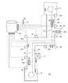
- FIG. 1 is a schematic diagram showing an example of the overall configuration of a vehicle driving support system 1.
- the vehicle driving support system 1 includes a monitoring device 5, an information processing device 50, a robot device 21, and a vehicle control device 30. Of these, the robot device 21 and the vehicle control device 30 are mounted on the vehicle 20, and the monitoring device 5 and the information processing device 50 are installed outside the vehicle 20.
- the information processing device 50 installed outside the vehicle 20 includes a plurality of monitoring devices 5a to 5j installed in a specific area (collectively referred to as the monitoring device 5 unless distinction is required). .) Is controlled based on the detection information of (.), And the vehicle 20 is run.
- the specific area may be an area that is set arbitrarily, but is set within a range in which at least the information processing device 50 and the vehicle 20 can communicate with each other via the wireless communication network. Further, when the monitoring device 5 and the information processing device 50 communicate with each other by wireless communication means, the specific area is set within a range in which the monitoring device 5 and the information processing device 50 can communicate.
- the vehicle 20 to be controlled is a vehicle in which an engine, a steering device, a brake device, a transmission, and the like operate due to at least a driver's steering wheel operation, accelerator operation, brake operation, or shift switching operation.
- the vehicle 20 may be the vehicle 20 in which at least one of these operations does not operate without being operated by the driver.
- the vehicle 20 may be a vehicle 20 that does not include at least a part of software or hardware for performing autonomous driving. For example, the vehicle 20 may not include at least one of the electric steering device and the automatic transmission.
- autonomous driving means a driving state in which some or all of the operations for adjusting the vehicle speed or the traveling direction of the vehicle 20 are performed without human hands.
- the monitoring device 5 is a device for monitoring the situation in a specific area.
- the monitoring device 5 includes one or more sensor elements of a radar sensor, a camera, an ultrasonic sensor, or a LIDAR.
- the monitoring device 5 is not particularly limited as long as it is a device that can detect an object within the monitoring range.
- the number of monitoring devices 5 installed in the specific area may be one or plural. However, it is preferable to install a plurality of monitoring devices so that the monitoring device 5 can monitor the entire range within the specific area. In particular, the monitoring device 5 is installed near a corner, an intersection of a traveling road, or a position where blind spots are likely to occur.
- the signal indicating the detection information by the monitoring device 5 is transmitted to the information processing device 50.
- the monitoring device 5 transmits a signal to the information processing device 50 by wired or wireless communication means.
- the information processing device 50 calculates information used for controlling the robot device 21 based on the detection information of the monitoring device 5, and transmits a signal indicating the information to the vehicle 20 via the communication network.
- the information processing device 50 is connected to the communication network via the base station 9, for example.
- the communication network may be a mobile network using a communication method such as Wi-Fi or LTE (Long Term Evolution).
- the information processing device 50 calculates area information, which is information within the specific area, based on the detection information of the monitoring device 5.
- the in-area information includes not only the surroundings of the vehicle 20 but also information indicating the status of other vehicles, objects, and facilities existing in the specific area.
- the in-area information is mainly used to set the traveling route of the vehicle 20.
- the information processing device 50 also calculates information on the traveling state of the vehicle 20 to be controlled, based on the detection information of the monitoring device 5.
- the information on the traveling state of the vehicle 20 includes information on the position, direction, vehicle speed, and traveling direction of the vehicle 20. Further, the information processing device 50 calculates the surrounding information of the vehicle 20 based on the detection information of the monitoring device 5.
- the surrounding information of the vehicle 20 includes information indicating the status of other vehicles, objects, persons, etc. existing around the vehicle 20.
- the information on the surroundings of the vehicle 20 is mainly used to determine the safety for autonomously driving the vehicle 20.
- the information processing device 50 calculates information used for controlling the robot device 21 mounted on the vehicle 20 based on the in-area information, the traveling state information of the vehicle 20, and the surrounding information of the vehicle 20, and transmits the information via the communication network.
- the information is transmitted to the vehicle 20.
- the information processing device 50 sets the traveling route of the vehicle 20 based on the in-area information, and determines the target position of the vehicle 20 after a predetermined time based on the traveling state information of the vehicle 20 and the surrounding information of the vehicle 20. Set.
- the information processing device 50 sets the target steering angle and the target acceleration of the vehicle 20 based on the target position of the vehicle 20, and uses the information used for controlling the robot device 21 according to the target steering angle and the target acceleration of the vehicle 20. Send to.
- the robot device 21 mounted on the vehicle 20 includes a first actuator 41 that operates the steering wheel 23, a second actuator 43 that operates the accelerator pedal 25, a third actuator 45 that operates the shift lever 27, and a brake (not shown).
- a fourth actuator is included to operate the pedal.
- a humanoid robot device 21 is shown in FIG. 1, the robot device 21 does not have to be humanoid. Further, the robot device 21 may be composed of a plurality of robot devices each including one or a plurality of actuators.
- the first actuator 41 rotates the steering wheel 23.
- the first actuator 41 may be a motor represented by a stepping motor, for example.
- the second actuator 43 and the fourth actuator respectively perform the depression operation of the accelerator pedal 25 or the brake pedal.
- the second actuator 43 and the fourth actuator may be actuators configured to move the piston back and forth by the output or hydraulic pressure of the motor, for example.
- the third actuator 45 moves the position of the shift lever 27.
- the biaxial robot apparatus 21a for moving the position of the shift lever 27 is provided, and the third actuator 45 is a motor for rotating the arm of the biaxial robot apparatus 21a.
- Each of these actuators can be installed at any position in the passenger compartment.
- Each actuator may be removable. If the actuator is removable, for example, when the vehicle driving support system 1 is abnormal, the actuator can be removed and the vehicle 20 can be driven by human hands.
- the configurations of the robot device 21 and each actuator are not limited to the above example.
- the vehicle control device 30 controls each actuator of the robot device 21 based on the information transmitted from the information processing device 50. That is, the vehicle control device 30 outputs a drive signal to each actuator according to the target operation amount of each actuator of the robot device 21 set according to the target steering angle and the target acceleration of the vehicle 20.
- FIG. 2 is a schematic diagram showing an application example of the vehicle driving support system 1 (1A).
- This application example is an example in which the vehicle driving support system is applied to a system for causing the vehicle 20 to travel between two different first points 11 and second points 13 existing in the specific area.
- the vehicle driving support system 1A shown in FIG. 2 is a system that causes the vehicle 20 to piston-transport a conveyed product between the first point 11 and the second point 13.
- a vehicle driving support system 1A can be applied to, for example, an in-house transportation system in a factory or a warehouse.
- Vehicle 20 is set to run at least in road 10.
- a plurality of (10 in the example of FIG. 2) monitoring devices 5a to 5j are installed along the road 10.
- the plurality of monitoring devices 5a to 5j output signals to the information processing device 50 according to the positions of vehicles, people, obstacles, etc. existing in a specific area including the road 10 and the periphery of the road 10.
- the merging point 15 where the road 10 and the passage 16 merge can be monitored by the monitoring devices 5b and 5c, and the surroundings of the obstacle 17 which can be a blind spot for the vehicle 20 can be monitored by the monitoring devices 5h, 5i and 5j.
- Each of the monitoring devices 5a to 5j outputs a signal to the information processing device 50 via wired or wireless communication means.
- the information processing device 50 calculates the in-area information, the running state information of the vehicle 20, and the surrounding condition information of the vehicle 20 based on the detection signals of the monitoring devices 5a to 5j. For example, in the state shown in FIG. 2, the information processing device 50 compares the information on the installation positions of the monitoring devices 5a to 5j stored in advance with the information processing device 50 to detect the inside of the area based on the detection information of all the monitoring devices 5a to 5j. As information, the positions of the road 10 and the vehicles 19a and 19b around the road 10, people, obstacles 17, etc. are specified. The information processing device 50 sets the travel route R for moving the vehicle 20 from the first point 11 to the second point 13 based on the area information.
- the information processing device 50 also specifies the position, direction, vehicle speed, and traveling direction of the vehicle 20 to be controlled, as information on the traveling state of the vehicle 20, based on the detection information of the monitoring devices 5a to 5j, for example.
- the information processing device 50 recognizes the vehicle 20 to be controlled by communicating with the vehicle control device 30 of the vehicle 20 existing at the first point 11, and then uses the monitoring devices 5a to 5j to detect the vehicle 20. Specify the position, direction, vehicle speed and heading.
- the information processing device 50 uses information on the surrounding conditions of the vehicle 20 to be controlled as information on the surrounding conditions of the vehicle 20 to be controlled, based on the detection information of the monitoring devices 5a, 5b, and 5c, for example. Identify the presence or absence. For example, in the state shown in FIG. 2, the information processing device 50 identifies that the other vehicle 19b is approaching the confluence point 15 ahead of the vehicle 20 in the traveling direction from the passage 16.
- the information processing device 50 sets the target position of the vehicle 20 after a predetermined time has elapsed, based on the calculated area information, the traveling state information of the vehicle 20, and the surrounding information of the vehicle 20. Further, the information processing device 50 transmits information used for controlling the robot device 21 mounted on the vehicle 20 according to the set target position of the vehicle 20 at predetermined time intervals via the base station 9 and the communication network. The information is transmitted to 20. Specifically, the information processing device 50 receives the detection information of the monitoring devices 5a to 5j at predetermined time intervals, and uses the information obtained by executing the predetermined arithmetic processing for controlling the robot device 21 at predetermined time intervals. Send to 20.
- the predetermined time may be set within a range of 0.3 to 1.0 seconds, for example, while considering the processing speed of the information processing device 50.
- the vehicle control device 30 mounted on the vehicle 20 receives the information transmitted from the information processing device 50, and controls the drive of each actuator of the robot device 21 based on the information. As a result, the steering angle and acceleration of the vehicle 20 are adjusted every predetermined time, and the vehicle 20 can be run from the first point 11 to the second point 13 while ensuring the safety of the vehicle 20.
- the information processing device 50 and the vehicle control device 30 perform the same processing. In this way, the vehicle driving support system 1A can safely move the vehicle 20 back and forth between the first point 11 and the second point 13 by the control from the outside of the vehicle 20.
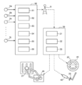
- FIG. 3 is a block diagram showing a first configuration example of the information processing device 50 and the vehicle control device 30.
- the information processing device 50 calculates the target position of the vehicle 20 after a predetermined time, and transmits information on the current position and the target position of the vehicle 20 to the vehicle control device 30.
- the vehicle control device 30 sets a target operation amount of each actuator of the robot device 21 based on the received information, and controls each actuator.
- the information processing device 50 includes a first communication unit 51, a second communication unit 52, a detected information processing unit 53, a route setting unit 54, a vehicle control information setting unit 55, and a storage unit 56.
- Part or all of the information processing device 50 may be configured by, for example, a microcomputer, a microprocessor unit, or the like, or may be configured by an updatable device such as firmware. Further, a part or all of the information processing device 50 may be a program module or the like executed by a command from the CPU or the like.
- the storage unit 56 includes a storage element such as a RAM (Random Access Memory) or a ROM (Read Only Memory), a storage device such as a HDD (Hard Disk Drive), a storage device, and a CD-ROM.
- the storage unit 56 stores a program executed by a microcomputer or the like, parameters used for various arithmetic processes, arithmetic results, detection information of various sensors, and the like.
- the first communication unit 51 is an interface for communicating between the monitoring device 5 and the information processing device 50.
- the information processing device 50 receives the signal output from the monitoring device 5 via the first communication unit 51.
- the second communication unit 52 is an interface for communicating between the vehicle control device 30 and the information processing device 50.
- the information processing device 50 transmits a signal to the vehicle control device 30 via the base station 9 and the communication network by the second communication unit 52.
- the detection information processing unit 53 performs various arithmetic processes using the detection information of the monitoring device 5.
- the detected information processing unit 53 may be a function realized by executing a program by a microcomputer or the like.
- the detection information processing unit 53 calculates the in-area information, the running state information of the vehicle 20, and the surrounding condition information of the vehicle 20 based on the detection information of the monitoring device 5.
- the route setting unit 54 sets the traveling route R of the vehicle 20.
- the route setting unit 54 may be a function realized by executing a program by a microcomputer or the like.
- the route setting unit 54 sets a traveling route R for traveling the vehicle 20 from the first point 11 to the second point 13 based on the calculated in-area information.
- the route setting unit 54 may be configured to set the traveling route R in the road 10 prestored in the storage unit 56.
- the route setting unit 54 may be omitted if the travel route R is set to be unchanged in advance.
- the vehicle control information setting unit 55 sets the target position of the vehicle 20 after a predetermined time, for each predetermined time.
- the vehicle control information setting unit 55 may be a function realized by executing a program by a microcomputer or the like.
- the vehicle control information setting unit 55 sets the target position of the vehicle 20 after a predetermined time based on the information on the traveling route R, the information on the traveling state of the vehicle 20, and the information on the surrounding conditions of the vehicle 20.
- the vehicle control information setting unit 55 transmits the set target position information to the vehicle control device 30 mounted on the vehicle 20 via the second communication unit 52.
- the information processing device 50 executes a setting process of the target position of the vehicle 20 after a predetermined time based on the detection information of the monitoring devices 5a to 5j and a transmission process of transmitting the information of the current position and the target position of the vehicle 20 every predetermined time.
- the predetermined time may be, for example, 1 to 5 seconds.
- the vehicle control device 30 includes a communication unit 31, a control information calculation unit 32, and a robot control unit 33.
- Part or all of the vehicle control device 30 may be configured by, for example, a microcomputer, a microprocessor unit, or the like, or may be configured by an updatable device such as firmware. Further, a part or all of the vehicle control device 30 may be a program module or the like executed by a command from a CPU or the like.
- the vehicle control device 30 may be composed of one electronic control unit, or may be composed of a plurality of electronic control units capable of communicating with each other. Further, the vehicle control device 30 may include a storage element (not shown) such as RAM or ROM.
- the communication unit 31 is an interface for communicating between the vehicle control device 30 and the information processing device 50.
- the vehicle control device 30 receives the signal transmitted from the vehicle control device 30 via the communication network by the communication unit 31.
- the control information calculation unit 32 sets the target operation amount of each actuator of the robot device 21 based on the information indicated by the signal received from the information processing device 50.
- the control information calculation unit 32 may be a function realized by executing a program by a microcomputer or the like.
- the control information calculator 32 sets the target steering angle and the target acceleration of the vehicle 20 based on the information on the current position and the target position of the vehicle 20 transmitted from the information processing device 50.
- control information calculation unit 32 sets the target steering angle and the target acceleration of the vehicle 20 based on the target position of the vehicle 20 after a predetermined time and the current position and orientation of the vehicle 20. Further, the control information calculation unit 32 sets a target operation amount of each actuator of the robot device 21 based on the set information on the target steering angle and the target acceleration of the vehicle 20.
- the robot controller 33 controls the operation of each actuator based on the target operation amount of each actuator set by the control information calculator 32.
- the robot control unit 33 includes, for example, a microcomputer and a drive circuit, and controls the drive circuit of each actuator according to the target operation amount of each actuator. At this time, an upper limit may be set for the amount of change (speed) of the operation amount of each actuator so that sudden steering or rapid acceleration of the vehicle 20 does not occur.
- the vehicle 20 is controlled by the information processing device 50 outside the vehicle 20, and the vehicle 20 can travel from the first point 11 to the second point 13 while ensuring the safety of the vehicle 20. ..
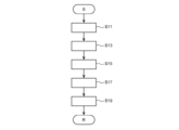
- FIG. 4 is a flowchart showing an operation example of the information processing device 50.
- the detection information processing unit 53 of the information processing device 50 acquires the detection information transmitted from the monitoring devices 5a to 5j via the first communication unit 51 (step S11).
- the detected information processing unit 53 calculates the information in the area, the information on the traveling state of the vehicle 20, and the information on the surrounding condition of the vehicle 20 based on the acquired detection information of the monitoring devices 5a to 5j (step S13).
- the route setting unit 54 of the information processing device 50 sets the traveling route R for traveling the vehicle 20 from the first point 11 to the second point 13 based on the in-area information (step S15). If the travel route R is set to be unchanged in advance, the process of step S15 may be omitted.
- the vehicle control information setting unit 55 of the information processing device 50 determines the target position of the vehicle 20 after a predetermined time based on the information on the traveling route R, the information on the traveling state of the vehicle 20, and the information on the surrounding conditions of the vehicle 20. It is set (step S17).
- the vehicle control information setting unit 55 sets the target position of the vehicle 20 after a predetermined time so that the vehicle 20 moves along the traveling route R at a preset acceleration. Then, when the position and traveling direction of the vehicle 20 deviate from the traveling route R, the vehicle control information setting unit 55 sets the target position of the vehicle 20 so as to return the vehicle 20 to the traveling route R. Further, when there is an obstacle such as a person or another vehicle on the travel route R, the vehicle control information setting unit 55 sets the target position of the vehicle 20 so as to avoid the obstacle. Avoiding the obstacle includes not only temporarily removing the vehicle 20 from the traveling route R but also decelerating or stopping the vehicle 20.
- the vehicle control information setting unit 55 controls the information about the set target position of the vehicle 20 and the information about the current position, direction and traveling direction of the vehicle 20 via the second communication unit 52 and the communication network.
- the data is transmitted to the device 30 (step S19).
- the information processing device 50 repeatedly executes each process from step S11 to step S19 at predetermined time intervals set in advance.
- the predetermined time may be set within a range of 0.3 to 1.0 seconds, for example, while considering the processing speed of the information processing device 50.
- FIG. 5 is a flowchart showing an operation example of the vehicle control device 30.
- the control information calculation unit 32 of the vehicle control device 30 includes information on the target position of the vehicle 20 after a predetermined time, which is transmitted from the information processing device 50 via the communication unit 31, and the current position, direction and traveling direction of the vehicle 20. And information of (step S31).
- control information calculation unit 32 sets the target steering angle and the target acceleration of the vehicle 20 based on the received target position of the vehicle 20 after the predetermined time and the information on the current position, direction, and traveling direction of the vehicle 20. Yes (step S33).
- the control information calculation unit 32 sets the target operation amount of each actuator of the robot device 21 based on the set target steering angle and target acceleration information (step S35). Specifically, the control information calculation unit 32 sets the target operation amount of the first actuator 41 that operates the steering wheel 23 based on the information on the target steering angle.
- the target operation amount is, for example, a rotation angle.
- control information calculation unit 32 based on the information on the target acceleration, the second actuator 43 that operates the accelerator pedal 25, the third actuator 45 that operates the shift lever 27, and the fourth actuator that operates a brake pedal (not shown).
- the target operation amount of the actuator is, for example, the stroke amount of the piston.
- the target operation amount is the rotation angle of each motor.
- control information calculation unit 32 refers to the map information of the operating point of the engine and the shift switching line of the transmission which are stored in advance, and based on the target acceleration, the target depression amount of the accelerator pedal 25 or the brake pedal and the shift lever. Set 27 target positions.
- the control information calculation unit 32 based on the set target depression amount of the accelerator pedal 25 or the brake pedal and the target position of the shift lever 27, sets the target operation amounts of the second actuator 43, the third actuator 45, and the fourth actuator. To set.
- control information calculation unit 32 transmits the set target operation amount of each actuator to the robot control unit 33 (step S37).
- the robot control unit 33 controls the drive circuit of each actuator based on the received target operation amount of each actuator to operate each actuator (step S39).
- the vehicle control device 30 repeatedly executes the processes from step S31 to step S39 at preset predetermined times.
- the information processing device 50 installed outside the vehicle 20 targets the vehicle 20 after a predetermined time based on the detection information of the monitoring device 5 installed in the specific area.
- the position is set, and information about the current position of the vehicle 20 is transmitted to the vehicle control device 30.
- the vehicle control device 30 controls the operation amount of each actuator of the robot device 21 installed in the vehicle 20, based on the received information on the current position and the target position of the vehicle 20.
- the steering wheel 23, the accelerator pedal 25, the brake pedal, and the shift lever 27 are operated by each actuator, and the traveling direction and speed of the vehicle 20 are adjusted. Therefore, even if the vehicle is not equipped with the autonomous driving technology, the information processing device 50 outside the vehicle 20 ensures the safety of the vehicle 20 while moving the vehicle 20 from the first point 11 to the second point. You can drive up to 13.
- the vehicle control device 30 is sufficient by controlling the drive of each actuator of the robot device 21, and the correction of the trajectory of the vehicle 20 is information based on the detection information of the monitoring devices 5a to 5j. It is performed by the processing device 50. Therefore, the vehicle driving support system 1 according to the present embodiment can be applied even to the vehicle 20 in which software or hardware that enables autonomous driving is not installed.
- the information processing device 50 sets the target position of the vehicle 20 after a predetermined time, and the vehicle control device 30 sets the target operation amount of each actuator of the robot device 21 mounted on the vehicle 20. To set. Therefore, since the vehicle control device 30 has information on the steering characteristic, the engine output characteristic, the brake characteristic, and the gear shift characteristic for each vehicle 20, the information processing device 50 is the same for vehicles having different characteristics. It is sufficient to transmit the control information, and the load on the information processing device 50 can be made relatively small.
- FIG. 6 is a block diagram showing a second configuration example of the information processing device 50 and the vehicle control device 30.
- the information processing device 50 calculates the target steering angle and the target acceleration of the vehicle 20 based on the information of the target position of the vehicle 20 after a predetermined time, and further the information of the target steering angle and the target acceleration.
- the information of the target operation amount of each actuator of the robot device 21 calculated based on the above is transmitted to the vehicle control device 30.
- the vehicle control device 30 controls each actuator based on the received information.
- the second configuration example is different from the first configuration example in that the target operation amount of each actuator of the robot device 21 is set by the information processing device 50 outside the vehicle 20.
- differences from the first configuration example will be mainly described.
- the information processing device 50 includes a first communication unit 51, a second communication unit 52, a detected information processing unit 53, a route setting unit 54, a vehicle control information setting unit 57, and a storage unit 56. Equipped with.
- the first communication unit 51, the second communication unit 52, the detected information processing unit 53, the route setting unit 54, and the storage unit 56 are the same as in the information processing device 50 of the first configuration example. Composed.
- the vehicle control information setting unit 57 sets the target position of the vehicle 20 after a predetermined time by the same procedure as the vehicle control information setting unit 55 of the first configuration example. Then, the vehicle control information setting unit 57 sets the target steering angle and the target acceleration of the vehicle 20 in accordance with the procedure performed by the control information calculation unit 32 of the vehicle control device 30 of the first configuration example, and the target The target operation amount of each actuator of the robot apparatus 21 is set based on the information on the steering angle and the target acceleration. The vehicle control information setting unit 57 transmits the set target operation amount information of each actuator to the vehicle control device 30 via the second communication unit 52 and the communication network.
- the vehicle control device 30 includes a communication unit 31 and a robot control unit 33.
- the vehicle control device 30 does not have a function corresponding to the control information calculation unit 32 of the vehicle control device 30 of the first configuration example.
- the robot controller 33 controls the operation of each actuator based on the target operation amount of each actuator transmitted from the information processing device 50.
- FIG. 7 is a flowchart showing an operation example of the information processing device 50.
- the detected information processing unit 53, the detected information processing unit 53, the route setting unit 54, and the vehicle control information setting unit 57 of the information processing device 50 respectively perform the processing of steps S11 to S17 shown in FIG.
- the target position of the vehicle 20 is calculated.
- the vehicle control information setting unit 57 follows the process of step S33 shown in FIG. 5 based on the target position of the vehicle 20 after a predetermined time and the current position, direction, and traveling direction of the vehicle 20.
- the target steering angle and the target acceleration of the vehicle 20 are set (step S21).
- the vehicle control information setting unit 57 sets the target operation amount of each actuator of the robot device 21 based on the set target steering angle and target acceleration information (step S23).
- the vehicle control information setting unit 57 transmits the set target operation amount information of each actuator to the vehicle control device 30 via the second communication unit 52 and the communication network (step S25).
- the information processing device 50 repeatedly executes each process from step S11 to step S25 at predetermined time intervals set in advance.
- FIG. 8 is a flowchart showing an operation example of the vehicle control device 30.
- the control information calculation unit 32 of the vehicle control device 30 acquires the information on the target operation amount of each actuator transmitted from the information processing device 50 via the communication unit 31 (step S36).
- the robot control unit 33 controls the drive circuit of each actuator based on the received target operation amount of each actuator to operate each actuator (step S37).
- the vehicle control device 30 repeatedly executes the processes from step S36 to step S37 at preset predetermined times.
- the information processing device 50 installed outside the vehicle 20 is mounted on the vehicle 20 based on the detection information of the monitoring device 5 installed in the specific area.
- the target operation amount of each actuator of the device 21 is set and transmitted to the vehicle control device 30. Further, the vehicle control device 30 controls the operation amount of each actuator of the robot device 21 based on the received target operation amount.
- the steering wheel 23, the accelerator pedal 25, the brake pedal, and the shift lever 27 are operated by each actuator, and the traveling direction and speed of the vehicle 20 are adjusted. Therefore, even if the vehicle is not equipped with the autonomous driving technology, the information processing device 50 outside the vehicle 20 ensures the safety of the vehicle 20 while moving the vehicle 20 from the first point 11 to the second point. You can drive up to 13.
- the vehicle control device 30 is sufficient by controlling the drive of each actuator of the robot device 21, and the trajectory of the vehicle 20 is corrected based on the detection information of the monitoring devices 5a to 5j. This is performed by the information processing device 50. Therefore, the vehicle driving support system 1 according to the present embodiment can be applied even to the vehicle 20 in which software or hardware that enables autonomous driving is not installed.
- the information processing device 50 sets the target operation amount of each actuator of the robot device 21 mounted on the vehicle 20 and sends it to the vehicle control device 30. Therefore, the information processing device 50 can store or set the steering characteristic, the engine output characteristic, the brake characteristic, and the shift characteristic information of the controlled vehicle 20, thereby controlling the vehicles having different characteristics. You can Therefore, the robot device 21 can be attached to and detached from the vehicle 20, and any vehicle 20 can be controlled from outside the vehicle 20. In this case, the vehicle 20 only needs to have the function of the robot control unit 33, so that the configuration of the vehicle control device 30 can be simplified.
- the vehicle driving support system 1 is a system in which all of the steering wheel 23, the accelerator pedal 25, the brake pedal, and the shift lever 27 of the vehicle 20 are operated by the robot device 21, but the present invention is applicable. It is not limited to the example.
- the vehicle driving support system may be a system in which a part of the steering wheel 23, the accelerator pedal 25, the brake pedal, and the shift lever 27 of the vehicle 20 is operated by the robot device 21.
- the robot device 21 when the vehicle 20 includes software and hardware that control the fuel injection amount or the intake amount of the engine and the gear ratio of the automatic transmission based on the target acceleration, the robot device 21 operates the accelerator pedal 25. The actuator and the third actuator for operating the shift lever 27 may not be provided.
- the robot device 21 includes the fourth actuator that operates the brake pedal. You don't have to.
- the robot device 21 operates the first actuator that operates the steering wheel 23. It does not have to be provided.
- the above-described embodiment is an example in which the transported material is piston-transported to the vehicle 20 between the first point 11 and the second point 13, and the information processing device 50 uses the detection information of the monitoring devices 5a to 5j.
- the vehicle 20 is controlled based on the above, the present invention is not limited to this example.
- the information processing apparatus 50 further determines the destination point and the target of the vehicle 20 based on the operating status information such as the production speed, the shipping speed, and the shipping status of the production line.
- Information used for controlling the robot device 21 may be calculated by setting the arrival time and the target position after a predetermined time.
- an obstacle may temporarily appear in the traveling route of the first vehicle or a situation in which the target arrival time cannot be met due to some influence is information.
- the processing device 50 determines, the second vehicle or the third vehicle may be controlled so that the shipping time of the physical distribution system is not delayed.
- the control target such as the traveling speed of the second vehicle having no obstacle on the traveling route may be changed, or the traveling of the waiting third vehicle may be started.
- the information processing device 50 controls the vehicles 20 while changing the number of vehicles 20 that support driving, the target arrival time of each vehicle 20, the traveling speed, etc., depending on whether or not it is in a busy period. May be.
- the in-house transportation system to which the vehicle driving support system 1 is applied is an example in which the vehicle 20 travels between two different first points 11 and second points 13.
- the present invention is not limited to such an example.
- the vehicle driving support system 1 may be applied to a system that moves the vehicle 20 from the first point to the second point via one or more intermediate points.
- the information processing device 50 sets the traveling route R from the first point to the second point via the intermediate point based on the detection information of the monitoring device 5 installed in the specific area, The vehicle 20 is controlled using the robot device 21.
- the vehicle driving support system can be applied to, for example, a person transportation system at an airport or an event site, or an automatic operation system for a garbage collection vehicle in a garbage collection facility (specific area).
- a person transportation system at an airport or an event site or an automatic operation system for a garbage collection vehicle in a garbage collection facility (specific area).
- the driver of the vehicle (garbage collection vehicle) 20 descends from the vehicle 20 at a preset start point, while the robot device 21 is attached to the vehicle 20 to start control.
- the vehicle 20 is used so as to automatically travel from the start point to the end point via the pit for removing the garbage and the car wash.
- the vehicle driving support system may be applied to an automatic valet parking (AVP) system.
- AVP automatic valet parking
- the information processing device 50 identifies a vacant space (parking position) based on the detection information of the monitoring device 5 installed in the specific parking area, and also the travel route from the transfer position of the vehicle 20 to the parking position. While setting R, the vehicle 20 is controlled using the robot device 21. When another vehicle parks at the parking position before the vehicle 20 reaches the parking position, the information processing device 50 changes the target parking position and resets the traveling route R.
- Such a system is used not only in a parking area but also in a rental car facility as a system for moving the vehicle 20 from a transfer place to an empty space, or moving the vehicle 20 from the empty space to the transfer place. In this way, the vehicle driving support system 1 can safely move the vehicle 20 between the delivery place and the parking position.
- the information processing device 50 may include a plurality of devices, and the functions of the information processing device 50 described above may be distributed and provided in the plurality of devices.
- AVP automatic valet parking system
- a server (first device) of a host system specifies a parking position according to various conditions and travels to the parking position.
- the function of the route setting unit 54 for setting the route R is provided, and the server (second device) of the lower system receives the vehicle 20 based on the detection information of the monitoring devices 5a to 5j according to the traveling route R received from the upper system.
- a function of the vehicle control information setting unit 55 that sets and transmits control information may be provided.
- the information processing device 50 may include the route setting unit 54 that sets the first traveling route, and may receive information on another traveling route (second traveling route) from the server of the host system.
- the route setting unit 54 of the information processing device 50 may select any one of the traveling routes R in consideration of at least one of safety, distance, and time.
- SYMBOLS 1 Vehicle driving support system, 5 ... Monitoring device, 9 ... Base station, 20 ... Vehicle, 21 ... Robot device, 23 ... Steering wheel, 25 ... Accelerator pedal, 27 ... shift lever, 30 ... vehicle control device, 31 ... communication unit, 32 ... control information calculation unit, 33 ... robot control unit, 41 ... first actuator, 43 ... ..Second actuator, 45 ... Third actuator, 50 ... Information processing device, 51 ... First communication unit, 52 ... Second communication unit, 53 ... Detection information Processing unit, 54 ... Route setting unit, 55 ... Vehicle control information setting unit, 56 ... Storage unit, R ... Travel route
Landscapes
- Physics & Mathematics (AREA)
- General Physics & Mathematics (AREA)
- Traffic Control Systems (AREA)
- Steering Control In Accordance With Driving Conditions (AREA)
- Control Of Driving Devices And Active Controlling Of Vehicle (AREA)
Abstract
【課題】車速又は進行方向を電子制御するためのソフトウェア又はハードウェアを備えていない車両に対しても適用可能な車両運転支援システムを提供する。 【解決手段】車両(20)の運転を外部から制御する車両運転支援システム(1)において、特定エリア内に設置された監視装置(5)と、車両(20)に搭載され、ステアリングホイール(23)、アクセルペダル(25)、ブレーキペダル又はシフトレバー(27)のうちの少なくとも一つを操作する少なくとも一つのロボット装置(21)と、車両(20)の外部に設置され、監視装置(5)の検出情報に基づいてロボット装置(21)の制御に用いる情報を演算し、通信ネットワークを介して車両(20)に情報を送信する情報処理装置(50)と、車両(20)に搭載され、情報処理装置(50)から送信される情報に基づいてロボット装置(21)を制御する車両制御装置(30)と、を備える。
Description
本発明は、車両運転支援システムに関する。
近年車両外部の装置により車両の運転を制御するシステムが提案されている。例えば特許文献1には、開始位置から目標位置に至る駐車場におけるルートを車両外部で特定し、当該ルートのうち少なくとも1つの区間を、通信ネットワークを介して車両に送信し、上記区間を辿る走行時、当該区間を辿る自律走行中の逸脱について、車両外部の監視システムによって当該車両を監視する駐車場の誘導方法が開示されている。
しかしながら、特許文献1に開示の技術は、車両の進行方向及び車速を車両の外部から制御可能な自律運転技術を搭載した車両の制御を前提としている。このため、運転者の操作によらずに外部から操作可能な自動変速機、ステアリング装置又は加減速装置を備えていない車両等、車速又は進行方向を電子制御するためのソフトウェア又はハードウェアを備えていない車両には適用することができない。
本発明は上記問題に鑑みてなされたものであり、自律運転技術を搭載していないあるいは部分的にしか搭載していない車両に対しても適用可能な車両運転支援システムを提供することを目的とする。
本発明のある観点によれば、車両の運転を外部から制御する車両運転支援システムにおいて、特定エリア内に設置された監視装置と、車両に搭載され、ステアリングホイール、アクセルペダル、ブレーキペダル又はシフトレバーのうちの少なくとも一つを操作する少なくとも一つのロボット装置と、車両の外部に設置され、監視装置の検出情報に基づいてロボット装置の制御に用いる情報を演算し、通信ネットワークを介して車両に情報を送信する情報処理装置と、車両に搭載され、情報処理装置から送信される情報に基づいてロボット装置を制御する車両制御装置と、を備える、車両運転支援システムが提供される。
また、本発明の別の観点によれば、車両の運転を外部から制御する車両運転支援方法において、車両の外部に設置された情報処理装置が、特定エリア内に設置された監視装置の検出情報に基づいて、車両に搭載され、ステアリングホイール、アクセルペダル、ブレーキペダル又はシフトレバーのうちの少なくとも一つを操作する少なくとも一つのロボット装置の制御に用いる情報を演算し、通信ネットワークを介して車両に情報を送信するステップと、車両に搭載された車両制御装置が、情報処理装置から送信される情報に基づいてロボット装置を制御するステップと、を備える、車両運転支援方法が提供される。
以上説明したように本発明によれば、自律運転技術を搭載していない車両に対しても車両運転支援システムを適用することができる。
以下、添付図面を参照しながら本発明の好適な実施の形態について詳細に説明する。なお、本明細書及び図面において、実質的に同一の機能構成を有する構成要素については同一の符号を付することにより重複説明を省略する。
<1.車両運転支援システムの全体構成例>
図1を参照して、本実施形態に係る車両運転支援システム1の全体構成例を説明する。図1は、車両運転支援システム1の全体構成例を示す模式図である。
図1を参照して、本実施形態に係る車両運転支援システム1の全体構成例を説明する。図1は、車両運転支援システム1の全体構成例を示す模式図である。
車両運転支援システム1は、監視装置5、情報処理装置50、ロボット装置21及び車両制御装置30を備える。このうち、ロボット装置21及び車両制御装置30は車両20に搭載され、監視装置5及び情報処理装置50は車両20の外部に設置される。車両運転支援システム1は、車両20の外部に設置された情報処理装置50が、特定エリア内に設置された複数の監視装置5a~5j(特に区別を要しない場合には監視装置5と総称する。)の検出情報に基づいて車両20を制御し、車両20を走行させるシステムである。
特定エリアは、任意に設定されるエリアであってよいが、少なくとも情報処理装置50と車両20とが無線通信ネットワークを介して通信可能な範囲内で設定される。さらに、監視装置5と情報処理装置50とが無線通信手段により通信を行う場合、特定エリアは、監視装置5と情報処理装置50とが通信可能な範囲内で設定される。
制御対象となる車両20は、少なくとも運転者のハンドル操作、アクセル操作、ブレーキ操作又はシフト切換操作に起因してエンジン、ステアリング装置、ブレーキ装置、変速機等が動作する車両である。車両20は、これらの動作の少なくとも1つが運転者の操作によらずに作動しない車両20であってもよい。車両20は、自律運転を行うためのソフトウェア又はハードウェアの少なくとも一部を備えていない車両20であってよい。例えば、車両20は、電動ステアリング装置又は自動変速機の少なくとも一方を備えていなくてもよい。
なお、本明細書において、自律運転とは、車両20の車速又は進行方向を調節する操作のうちの一部又は全部が、人の手によらずに行われる運転状態をいう。
監視装置5は、特定エリア内の状況を監視するための装置である。監視装置5は、レーダーセンサ、カメラ、超音波センサ又はLIDARのうちの一つ又は複数のセンサ素子を備える。監視装置5は、監視範囲内の物体を検知できる装置であれば特に限定されるものではない。
特定エリア内に設置される監視装置5の数は、一つであってもよく複数であってもよい。ただし、監視装置5によって特定エリア内の全範囲を監視可能にするために、複数の監視装置が設置されることが好ましい。特に、監視装置5は、曲がり角や走行路の交差点、死角となりやすい位置の付近に設置される。監視装置5による検出情報を示す信号は、情報処理装置50に送信される。監視装置5は、有線又は無線の通信手段により、情報処理装置50に対して信号を送信する。
情報処理装置50は、監視装置5の検出情報に基づいてロボット装置21の制御に用いる情報を演算し、当該情報を示す信号を、通信ネットワークを介して車両20に送信する。情報処理装置50は、例えば基地局9を介して通信ネットワークに接続される。通信ネットワークは、例えばWi-FiやLTE(Long Term Evolution)等の通信方式を利用したモバイルネットワークであってよい。
情報処理装置50は、監視装置5の検出情報に基づいて、特定エリア内の情報であるエリア内情報を算出する。エリア内情報は、車両20の周囲に限らず特定エリア内に存在する他車両や物、施設の状況を示す情報を含む。エリア内情報は、主として、車両20の走行ルートを設定するために用いられる。
また、情報処理装置50は、監視装置5の検出情報に基づいて、制御対象の車両20の走行状態の情報を算出する。車両20の走行状態の情報は、車両20の位置、向き、車速及び進行方向の情報を含む。また、情報処理装置50は、監視装置5の検出情報に基づいて、車両20の周囲情報を算出する。車両20の周囲情報とは、車両20の周囲に存在する他車両や物、人物等の状況を示す情報を含む。車両20の周囲情報は、主として、車両20を自律走行させるための安全性を判断するために用いられる。
情報処理装置50は、エリア内情報、車両20の走行状態の情報及び車両20の周囲情報に基づいて、車両20に搭載されたロボット装置21の制御に用いる情報を演算し、通信ネットワークを介して車両20に当該情報を送信する。例えば、情報処理装置50は、エリア内情報に基づいて車両20の走行ルートを設定し、車両20の走行状態の情報及び車両20の周囲情報に基づいて、所定時間後の車両20の目標位置を設定する。
情報処理装置50は、車両20の目標位置に基づいて車両20の目標舵角及び目標加速度を設定するとともに、これらの目標舵角及び目標加速度に応じたロボット装置21の制御に用いる情報を車両20に送信する。
車両20に搭載されたロボット装置21は、ステアリングホイール23を動作させる第1のアクチュエータ41、アクセルペダル25を動作させる第2のアクチュエータ43、シフトレバー27を動作させる第3のアクチュエータ45及び図示しないブレーキペダルを動作させる第4のアクチュエータを含む。図1には、人型のロボット装置21が示されているが、ロボット装置21は人型でなくてもよい。また、ロボット装置21は、それぞれ一つ又は複数のアクチュエータを備えた複数のロボット装置からなっていてもよい。
第1のアクチュエータ41は、ステアリングホイール23を回転動作させる。第1のアクチュエータ41は、例えばステッピングモータに代表されるモータであってよい。第2のアクチュエータ43及び第4のアクチュエータは、それぞれアクセルペダル25又はブレーキペダルの踏込動作を行う。第2のアクチュエータ43及び第4のアクチュエータは、例えばモータの出力又は油圧によりピストンを進退動させる構成のアクチュエータであってよい。第3のアクチュエータ45は、シフトレバー27の位置を移動させる。図1に示した例では、シフトレバー27の位置を移動させる二軸ロボット装置21aが備えられ、第3のアクチュエータ45は、二軸ロボット装置21aのアームを回転動作させるモータである。
これらの各アクチュエータは、車室内の任意の位置に取り付けられる。各アクチュエータは、取外し可能にされていてもよい。アクチュエータが取外し可能になっていれば、例えば車両運転支援システム1の異常時等にアクチュエータを取外し、人の手によって車両20を運転することができる。なお、ロボット装置21及び各アクチュエータの構成は上記の例に限られない。
車両制御装置30は、情報処理装置50から送信される情報に基づいてロボット装置21の各アクチュエータを制御する。つまり、車両制御装置30は、車両20の目標舵角及び目標加速度に応じて設定されるロボット装置21の各アクチュエータの目標操作量に応じて各アクチュエータに駆動信号を出力する。
<2.車両運転支援システムの適用例>
次に、図2を参照して、本実施形態に係る車両運転支援システム1の適用例を説明する。図2は、車両運転支援システム1(1A)の適用例を示す模式図である。かかる適用例は、車両20を、特定エリア内に存在する二つの異なる第1の地点11及び第2の地点13の間を走行させるためのシステムに車両運転支援システムを適用した例である。
次に、図2を参照して、本実施形態に係る車両運転支援システム1の適用例を説明する。図2は、車両運転支援システム1(1A)の適用例を示す模式図である。かかる適用例は、車両20を、特定エリア内に存在する二つの異なる第1の地点11及び第2の地点13の間を走行させるためのシステムに車両運転支援システムを適用した例である。
図2に示した車両運転支援システム1Aは、車両20に、第1の地点11と第2の地点13との間で搬送物をピストン輸送させるシステムである。かかる車両運転支援システム1Aは、例えば工場あるいは倉庫等における構内輸送システムに適用することができる。車両20は、少なくとも車路10内を走行するように設定される。
車路10に沿って複数(図2の例では10個)の監視装置5a~5jが設置されている。複数の監視装置5a~5jは、車路10及び車路10の周囲を含む特定エリア内に存在する車両、人物、障害物等の位置に応じた信号を情報処理装置50に出力する。特に、車路10と通路16とが合流する合流地点15は監視装置5b,5cにより監視可能にされ、車両20にとって死角となり得る障害物17の周囲は監視装置5h,5i,5jにより監視可能にされる。それぞれの監視装置5a~5jは、有線又は無線の通信手段を介して情報処理装置50に信号を出力する。
情報処理装置50は、監視装置5a~5jの検出信号に基づいて、エリア内情報、車両20の走行状態の情報及び車両20の周囲状況の情報を算出する。例えば、図2に示す状態において、情報処理装置50は、あらかじめ記憶された監視装置5a~5jの設置位置の情報と照らし合わせながら、すべての監視装置5a~5jの検出情報に基づいて、エリア内情報として、車路10及び車路10の周囲の車両19a,19b、人物、障害物17等の位置を特定する。情報処理装置50は、当該エリア内情報に基づいて、第1の地点11から第2の地点13に車両20を移動させる走行ルートRを設定する。
また、情報処理装置50は、例えば監視装置5a~5jの検出情報に基づいて、車両20の走行状態の情報として、制御対象の車両20の位置、向き、車速及び進行方向を特定する。例えば、情報処理装置50は、第1の地点11に存在する車両20の車両制御装置30と通信することにより制御対象の車両20を認識した後、監視装置5a~5jを用いて当該車両20の位置、向き、車速及び進行方向を特定する。
また、情報処理装置50は、例えば監視装置5a,5b,5cの検出情報に基づいて、制御対象の車両20の周囲状況の情報として、走行ルートRに沿って車両20が走行する際の障害の有無を特定する。例えば、図2に示す状態において、情報処理装置50は、車両20の進行方向前方の合流地点15に対して、通路16から他の車両19bが迫っていることを特定する。
情報処理装置50は、算出したエリア内情報、車両20の走行状態の情報及び車両20の周囲状況の情報に基づいて、所定時間経過後の車両20の目標位置を設定する。さらに、情報処理装置50は、設定した車両20の目標位置に応じた、車両20に搭載されたロボット装置21の制御に用いる情報を、所定時間ごとに、基地局9及び通信ネットワークを介して車両20に対して当該情報を送信する。具体的に、情報処理装置50は、所定時間ごとに監視装置5a~5jの検出情報を受信し、所定の演算処理の実行により得られたロボット装置21の制御に用いる情報を所定時間ごとに車両20に対して送信する。所定時間は、情報処理装置50の処理速度を考慮しつつ、例えば0.3~1.0秒の範囲内に設定されてよい。
車両20に搭載された車両制御装置30は、情報処理装置50から送信される情報を受信し、当該情報に基づいてロボット装置21の各アクチュエータの駆動を制御する。これにより、所定時間ごとに車両20の舵角及び加速度が調節され、車両20の安全性を確保しつつ、車両20を第1の地点11から第2の地点13まで走行させることができる。
車両20を第2の地点13から第1の地点11へと走行させる際にも、情報処理装置50及び車両制御装置30は同様の処理を行う。このようにして、車両運転支援システム1Aは、車両20の外部からの制御により、車両20を、第1の地点11と第2の地点13との間を安全に行き来させることができる。
<3.情報処理装置及び車両制御装置の構成例>
以下、図2に示した車両運転支援システム1Aに用いられる情報処理装置50及び車両制御装置30の構成例を説明する。
以下、図2に示した車両運転支援システム1Aに用いられる情報処理装置50及び車両制御装置30の構成例を説明する。
(3-1.第1の構成例)
図3は、情報処理装置50及び車両制御装置30の第1の構成例を示すブロック図である。第1の構成例では、情報処理装置50は、所定時間後の車両20の目標位置を算出し、車両20の現在位置及び目標位置の情報を車両制御装置30に送信する。車両制御装置30は、受信した情報に基づいて、ロボット装置21の各アクチュエータの目標操作量を設定し、各アクチュエータを制御する。
図3は、情報処理装置50及び車両制御装置30の第1の構成例を示すブロック図である。第1の構成例では、情報処理装置50は、所定時間後の車両20の目標位置を算出し、車両20の現在位置及び目標位置の情報を車両制御装置30に送信する。車両制御装置30は、受信した情報に基づいて、ロボット装置21の各アクチュエータの目標操作量を設定し、各アクチュエータを制御する。
(情報処理装置)
情報処理装置50は、第1の通信部51、第2の通信部52、検出情報処理部53、ルート設定部54、車両制御情報設定部55及び記憶部56を備える。情報処理装置50の一部又は全部は、例えば、マイクロコンピュータ又はマイクロプロセッサユニット等で構成されていてもよく、ファームウェア等の更新可能なもので構成されていてもよい。また、情報処理装置50の一部又は全部は、CPU等からの指令によって実行されるプログラムモジュール等であってもよい。
情報処理装置50は、第1の通信部51、第2の通信部52、検出情報処理部53、ルート設定部54、車両制御情報設定部55及び記憶部56を備える。情報処理装置50の一部又は全部は、例えば、マイクロコンピュータ又はマイクロプロセッサユニット等で構成されていてもよく、ファームウェア等の更新可能なもので構成されていてもよい。また、情報処理装置50の一部又は全部は、CPU等からの指令によって実行されるプログラムモジュール等であってもよい。
記憶部56は、RAM(Random Access Memory)又はROM(Read Only Memory)等の記憶素子や、HDD(Hard Disk Drive)やストレージ装置、CD-ROM等の記憶装置を含む。記憶部56は、マイクロコンピュータ等により実行されるプログラムや各種演算処理に用いられるパラメータ、演算結果、各種センサ等の検出情報等を記憶する。
第1の通信部51は、監視装置5と情報処理装置50との間で通信を行うためのインタフェースである。情報処理装置50は、第1の通信部51を介して監視装置5から出力される信号を受信する。
第2の通信部52は、車両制御装置30と情報処理装置50との間で通信を行うためのインタフェースである。情報処理装置50は、第2の通信部52により、基地局9及び通信ネットワークを介して車両制御装置30に対して信号を送信する。
検出情報処理部53は、監視装置5の検出情報を用いて種々の演算処理を行う。例えば、検出情報処理部53は、マイクロコンピュータ等によるプログラムの実行により実現される機能であってよい。検出情報処理部53は、監視装置5の検出情報に基づいて、エリア内情報、車両20の走行状態の情報及び車両20の周囲状況の情報を算出する。
ルート設定部54は、車両20の走行ルートRを設定する。例えば、ルート設定部54は、マイクロコンピュータ等によるプログラムの実行により実現される機能であってよい。ルート設定部54は、算出されたエリア内情報に基づいて、車両20を第1の地点11から第2の地点13まで走行させるための走行ルートRを設定する。ルート設定部54は、記憶部56にあらかじめ記憶された車路10内において、走行ルートRを設定するよう構成されていてよい。
なお、あらかじめ走行ルートRを不変に設定されている場合には、ルート設定部54が省略されていてもよい。
車両制御情報設定部55は、所定時間ごとに、所定時間後の車両20の目標位置を設定する。例えば、車両制御情報設定部55は、マイクロコンピュータ等によるプログラムの実行により実現される機能であってよい。車両制御情報設定部55は、走行ルートRの情報、車両20の走行状態の情報及び車両20の周囲状況の情報に基づいて、所定時間後の車両20の目標位置を設定する。車両制御情報設定部55は、設定した目標位置の情報を、第2の通信部52を介して車両20に搭載された車両制御装置30に送信する。
情報処理装置50は、監視装置5a~5jの検出情報に基づく所定時間後の車両20の目標位置の設定処理と、車両20の現在位置及び目標位置の情報の送信処理とを所定時間ごとに実行する。所定時間は、例えば1~5秒であってよい。
(車両制御装置)
車両制御装置30は、通信部31、制御情報演算部32及びロボット制御部33を備える。車両制御装置30の一部又は全部は、例えば、マイクロコンピュータ又はマイクロプロセッサユニット等で構成されていてもよく、ファームウェア等の更新可能なもので構成されていてもよい。また、車両制御装置30の一部又は全部は、CPU等からの指令によって実行されるプログラムモジュール等であってもよい。
車両制御装置30は、通信部31、制御情報演算部32及びロボット制御部33を備える。車両制御装置30の一部又は全部は、例えば、マイクロコンピュータ又はマイクロプロセッサユニット等で構成されていてもよく、ファームウェア等の更新可能なもので構成されていてもよい。また、車両制御装置30の一部又は全部は、CPU等からの指令によって実行されるプログラムモジュール等であってもよい。
車両制御装置30は、一つの電子制御ユニットにより構成されていてもよく、互いに通信可能な複数の電子制御ユニットにより構成されていてもよい。また、車両制御装置30は、RAMやROM等の図示しない記憶素子を備えていてもよい。
通信部31は、車両制御装置30と情報処理装置50との間で通信を行うためのインタフェースである。車両制御装置30は、通信部31により、通信ネットワークを介して車両制御装置30から送信される信号を受信する。
制御情報演算部32は、情報処理装置50から受信した信号が示す情報に基づいて、ロボット装置21の各アクチュエータの目標操作量を設定する。例えば、制御情報演算部32は、マイクロコンピュータ等によるプログラムの実行により実現される機能であってよい。制御情報演算部32は、情報処理装置50から送信される車両20の現在位置及び目標位置の情報に基づいて、車両20の目標舵角及び目標加速度を設定する
具体的に、制御情報演算部32は、所定時間後の車両20の目標位置と、車両20の現在の位置及び向きとに基づいて、車両20の目標舵角及び目標加速度を設定する。また、制御情報演算部32は、設定した車両20の目標舵角及び目標加速度の情報に基づいて、ロボット装置21の各アクチュエータの目標操作量を設定する。
ロボット制御部33は、制御情報演算部32により設定された各アクチュエータの目標操作量に基づいて各アクチュエータの動作を制御する。ロボット制御部33は、例えばマイクロコンピュータ及び駆動回路を備えて構成され、各アクチュエータの目標操作量にしたがって各アクチュエータの駆動回路を制御する。このとき、各アクチュエータの操作量の変化量(速度)には上限が設定され、車両20の急ハンドルや急加速が生じないようになっていてもよい。
これにより、車両20は、車両20の外部の情報処理装置50によって制御され、車両20の安全性を確保しつつ、車両20を第1の地点11から第2の地点13まで走行させることができる。
(情報処理装置及び車両制御装置の動作例)
次に、第1の構成例に係る情報処理装置50及び車両制御装置30の動作例を説明する。
次に、第1の構成例に係る情報処理装置50及び車両制御装置30の動作例を説明する。
図4は、情報処理装置50の動作例を示すフローチャートである。情報処理装置50の検出情報処理部53は、第1の通信部51を介して、監視装置5a~5jから送信される検出情報を取得する(ステップS11)。
次いで、検出情報処理部53は、取得した監視装置5a~5jの検出情報に基づいて、エリア内情報、車両20の走行状態の情報及び車両20の周囲状況の情報を算出する(ステップS13)。
次いで、情報処理装置50のルート設定部54は、エリア内情報に基づいて、車両20を第1の地点11から第2の地点13まで走行させるための走行ルートRを設定する(ステップS15)。なお、あらかじめ走行ルートRを不変に設定されている場合には、ステップS15の処理が省略されていてもよい。
次いで、情報処理装置50の車両制御情報設定部55は、走行ルートRの情報、車両20の走行状態の情報及び車両20の周囲状況の情報に基づいて、所定時間後の車両20の目標位置を設定する(ステップS17)。
基本的に、車両制御情報設定部55は、車両20が走行ルートRに沿って、あらかじめ設定された加速度で移動するように所定時間後の車両20の目標位置を設定する。そのうえで、車両20の位置及び進行方向が走行ルートRから外れている場合に、車両制御情報設定部55は、車両20を走行ルートR上に戻すように車両20の目標位置を設定する。また、走行ルートR上に、人物や他の車両等の障害が存在する場合に、車両制御情報設定部55は、当該障害を回避するように車両20の目標位置を設定する。障害を回避することには、車両20を一時的に走行ルートRから外させることだけでなく、車両20を減速させたり停止させたりすることも含む。
次いで、車両制御情報設定部55は、設定した車両20の目標位置の情報と、車両20の現在位置、向き及び進行方向の情報とを、第2の通信部52及び通信ネットワークを介して車両制御装置30に送信する(ステップS19)。
情報処理装置50は、ステップS11~ステップS19までの各処理をあらかじめ設定した所定時間ごとに繰り返し実行する。所定時間は、情報処理装置50の処理速度を考慮しつつ、例えば0.3~1.0秒の範囲内に設定されてよい。
図5は、車両制御装置30の動作例を示すフローチャートである。車両制御装置30の制御情報演算部32は、通信部31を介して、情報処理装置50から送信される車両20の所定時間後の目標位置の情報と、車両20の現在位置、向き及び進行方向の情報とを取得する(ステップS31)。
次いで、制御情報演算部32は、受信した所定時間後の車両20の目標位置と、車両20の現在位置、向き及び進行方向の情報とに基づいて、車両20の目標舵角及び目標加速度を設定する(ステップS33)。
次いで、制御情報演算部32は、設定した目標舵角及び目標加速度の情報に基づいて、ロボット装置21の各アクチュエータの目標操作量を設定する(ステップS35)。具体的に、制御情報演算部32は、目標舵角の情報に基づいて、ステアリングホイール23を動作させる第1のアクチュエータ41の目標操作量を設定する。第1のアクチュエータ41がステッピングモータ等のモータである場合、目標操作量は、例えば回転角度である。
また、制御情報演算部32は、目標加速度の情報に基づいて、アクセルペダル25を動作させる第2のアクチュエータ43、シフトレバー27を動作させる第3のアクチュエータ45及び図示しないブレーキペダルを動作させる第4のアクチュエータの目標操作量を設定する。第2のアクチュエータ43及び第4のアクチュエータがピストンを進退動させる構成のアクチュエータである場合、目標操作量は、例えばピストンのストローク量である。また、第3のアクチュエータ45が二軸ロボット装置21aのアームを回転動作させるモータである場合、目標操作量は、各モータの回転角度である。
例えば、制御情報演算部32は、あらかじめ記憶されたエンジンの動作点及び変速機のシフト切換線のマップ情報を参照しつつ、目標加速度に基づいてアクセルペダル25又はブレーキペダルの目標踏込量及びシフトレバー27の目標位置を設定する。制御情報演算部32は、設定したアクセルペダル25又はブレーキペダルの目標踏込量及びシフトレバー27の目標位置に基づいて、第2のアクチュエータ43、第3のアクチュエータ45及び第4のアクチュエータの目標操作量を設定する。
次いで、制御情報演算部32は、設定した各アクチュエータの目標操作量をロボット制御部33に送信する(ステップS37)。
次いで、ロボット制御部33は、受信した各アクチュエータの目標操作量に基づいて、各アクチュエータの駆動回路の制御し、各アクチュエータを作動させる(ステップS39)。
車両制御装置30は、ステップS31~ステップS39までの各処理をあらかじめ設定した所定時間ごとに繰り返し実行する。
以上説明した第1の構成例によれば、車両20の外部に設置された情報処理装置50が、特定エリア内に設置された監視装置5の検出情報に基づいて所定時間後の車両20の目標位置を設定し、車両20の現在位置の情報とともに車両制御装置30に送信する。また、車両制御装置30は、受信した車両20の現在位置及び目標位置の情報に基づいて、車両20に設置されたロボット装置21の各アクチュエータの操作量を制御する。
これにより、ステアリングホイール23、アクセルペダル25、ブレーキペダル及びシフトレバー27が各アクチュエータによって動作され、車両20の進行方向及び速度が調節される。したがって、自律運転技術が搭載されていない車両であっても、車両20の外部の情報処理装置50によって、車両20の安全性を確保しつつ、車両20を第1の地点11から第2の地点13まで走行させることができる。
また、第1の構成例では、車両制御装置30は、ロボット装置21の各アクチュエータの駆動を制御することで足り、車両20の軌道の修正は、監視装置5a~5jの検出情報に基づいて情報処理装置50により行われる。このため、自律運転を可能にするソフトウェア又はハードウェアが搭載されていない車両20であっても、本実施形態に係る車両運転支援システム1を適用することができる。
なお、第1の構成例では、情報処理装置50が、所定時間後の車両20の目標位置を設定し、車両制御装置30が、車両20に搭載されたロボット装置21の各アクチュエータの目標操作量を設定する。このため、車両制御装置30が、車両20ごとのステアリング特性、エンジンの出力特性、ブレーキ特性及び変速特性の情報を持つことで、情報処理装置50は、これらの特性の異なる車両に対しても同じ制御情報を送信すれば足り、情報処理装置50の負荷を比較的小さくすることができる。
(3-2.第2の構成例)
図6は、情報処理装置50及び車両制御装置30の第2の構成例を示すブロック図である。第2の構成例では、情報処理装置50は、所定時間後の車両20の目標位置の情報に基づいて車両20の目標舵角及び目標加速度を算出し、さらに当該目標舵角及び目標加速度の情報に基づいて算出されるロボット装置21の各アクチュエータの目標操作量の情報を車両制御装置30に送信する。車両制御装置30は、受信した情報に基づいて、各アクチュエータを制御する。
図6は、情報処理装置50及び車両制御装置30の第2の構成例を示すブロック図である。第2の構成例では、情報処理装置50は、所定時間後の車両20の目標位置の情報に基づいて車両20の目標舵角及び目標加速度を算出し、さらに当該目標舵角及び目標加速度の情報に基づいて算出されるロボット装置21の各アクチュエータの目標操作量の情報を車両制御装置30に送信する。車両制御装置30は、受信した情報に基づいて、各アクチュエータを制御する。
第2の構成例は、ロボット装置21の各アクチュエータの目標操作量が、車両20の外部の情報処理装置50により設定される点において、第1の構成例とは異なる。以下、主として第1の構成例と異なる点を説明する。
(情報処理装置)
情報処理装置50は、第1の構成例と同様に、第1の通信部51、第2の通信部52、検出情報処理部53、ルート設定部54、車両制御情報設定部57及び記憶部56を備える。第2の構成例において、第1の通信部51、第2の通信部52、検出情報処理部53、ルート設定部54及び記憶部56は、第1の構成例の情報処理装置50と同様に構成される。
情報処理装置50は、第1の構成例と同様に、第1の通信部51、第2の通信部52、検出情報処理部53、ルート設定部54、車両制御情報設定部57及び記憶部56を備える。第2の構成例において、第1の通信部51、第2の通信部52、検出情報処理部53、ルート設定部54及び記憶部56は、第1の構成例の情報処理装置50と同様に構成される。
第2の構成例において、車両制御情報設定部57は、第1の構成例の車両制御情報設定部55と同様の手順で、所定時間後の車両20の目標位置を設定する。そして、車両制御情報設定部57は、第1の構成例の車両制御装置30の制御情報演算部32が行っていた手順に沿って、車両20の目標舵角及び目標加速度を設定するとともに、目標舵角及び目標加速度の情報に基づいて、ロボット装置21の各アクチュエータの目標操作量を設定する。車両制御情報設定部57は、設定した各アクチュエータの目標操作量の情報を、第2の通信部52及び通信ネットワークを介して、車両制御装置30に送信する。
(車両制御装置)
車両制御装置30は、通信部31及びロボット制御部33を備える。第2の構成例において、車両制御装置30は、第1の構成例の車両制御装置30の制御情報演算部32に相当する機能を備えていない。ロボット制御部33は、情報処理装置50から送信された各アクチュエータの目標操作量に基づいて各アクチュエータの動作を制御する。
車両制御装置30は、通信部31及びロボット制御部33を備える。第2の構成例において、車両制御装置30は、第1の構成例の車両制御装置30の制御情報演算部32に相当する機能を備えていない。ロボット制御部33は、情報処理装置50から送信された各アクチュエータの目標操作量に基づいて各アクチュエータの動作を制御する。
(情報処理装置及び車両制御装置の動作例)
次に、第2の構成例に係る情報処理装置50及び車両制御装置30の動作例を説明する。
次に、第2の構成例に係る情報処理装置50及び車両制御装置30の動作例を説明する。
図7は、情報処理装置50の動作例を示すフローチャートである。情報処理装置50の検出情報処理部53、検出情報処理部53、ルート設定部54及び車両制御情報設定部57は、それぞれ図4に示したステップS11~ステップS17の処理を行い、所定時間後の車両20の目標位置を算出する。
次いで、車両制御情報設定部57は、図5に示したステップS33の処理に沿って、所定時間後の車両20の目標位置と、車両20の現在位置、向き及び進行方向の情報とに基づいて、車両20の目標舵角及び目標加速度を設定する(ステップS21)。
次いで、車両制御情報設定部57は、設定した目標舵角及び目標加速度の情報に基づいて、ロボット装置21の各アクチュエータの目標操作量を設定する(ステップS23)。
次いで、車両制御情報設定部57は、設定した各アクチュエータの目標操作量の情報を、第2の通信部52及び通信ネットワークを介して車両制御装置30に送信する(ステップS25)。
情報処理装置50は、ステップS11~ステップS25までの各処理をあらかじめ設定した所定時間ごとに繰り返し実行する。
図8は、車両制御装置30の動作例を示すフローチャートである。車両制御装置30の制御情報演算部32は、通信部31を介して、情報処理装置50から送信される各アクチュエータの目標操作量の情報を取得する(ステップS36)。
次いで、ロボット制御部33は、受信した各アクチュエータの目標操作量に基づいて、各アクチュエータの駆動回路の制御し、各アクチュエータを作動させる(ステップS37)。
車両制御装置30は、ステップS36~ステップS37までの各処理をあらかじめ設定した所定時間ごとに繰り返し実行する。
以上説明した第2の構成例によれば、車両20の外部に設置された情報処理装置50が、特定エリア内に設置された監視装置5の検出情報に基づいて、車両20に搭載されたロボット装置21の各アクチュエータの目標操作量を設定して車両制御装置30に送信する。また、車両制御装置30は、受信した目標操作量に基づいて、ロボット装置21の各アクチュエータの操作量を制御する。
これにより、ステアリングホイール23、アクセルペダル25、ブレーキペダル及びシフトレバー27が各アクチュエータによって動作され、車両20の進行方向及び速度が調節される。したがって、自律運転技術が搭載されていない車両であっても、車両20の外部の情報処理装置50によって、車両20の安全性を確保しつつ、車両20を第1の地点11から第2の地点13まで走行させることができる。
また、第2の構成例においても、車両制御装置30は、ロボット装置21の各アクチュエータの駆動を制御することで足り、車両20の軌道の修正は、監視装置5a~5jの検出情報に基づいて情報処理装置50により行われる。このため、自律運転を可能にするソフトウェア又はハードウェアが搭載されていない車両20であっても、本実施形態に係る車両運転支援システム1を適用することができる。
なお、第2の構成例では、情報処理装置50が、車両20に搭載されたロボット装置21の各アクチュエータの目標操作量を設定し、車両制御装置30に送信する。このため、情報処理装置50は、制御対象の車両20のステアリング特性、エンジンの出力特性、ブレーキ特性及び変速特性の情報を記憶又は設定可能にすることで、これらの特性の異なる車両を制御することができる。したがって、車両20に対してロボット装置21を着脱可能にして、あらゆる車両20を車両20の外部から制御することができるようになる。この場合、車両20には、ロボット制御部33としての機能があれば足りるため、車両制御装置30の構成を簡素化することができる。
以上、添付図面を参照しながら本発明の好適な実施形態について詳細に説明したが、本発明はかかる例に限定されない。本発明の属する技術の分野における通常の知識を有する者であれば、特許請求の範囲に記載された技術的思想の範疇内において、各種の変更例または修正例に想到し得ることは明らかであり、これらについても、当然に本発明の技術的範囲に属するものと了解される。
例えば、上記実施形態において、車両運転支援システム1は、車両20のステアリングホイール23、アクセルペダル25、ブレーキペダル及びシフトレバー27のすべてをロボット装置21により動作させるシステムであったが、本発明はかかる例に限定されない。車両運転支援システムは、車両20のステアリングホイール23、アクセルペダル25、ブレーキペダル及びシフトレバー27のうちの一部をロボット装置21により動作させるシステムであってもよい。
例えば、車両20が、目標加速度に基づいてエンジンの燃料噴射量若しくは吸気量及び自動変速機の変速比を制御するソフトウェア及びハードウェアを備える場合、ロボット装置21が、アクセルペダル25を操作する第2のアクチュエータ及びシフトレバー27を操作する第3のアクチュエータを備えていなくてもよい。また、車両20が、目標加速度(目標減速度)に基づいて回生ブレーキ又は油圧式ブレーキシステムを制御するソフトウェア及びハードウェアを備える場合、ロボット装置21が、ブレーキペダルを操作する第4のアクチュエータを備えていなくてもよい。車両20が、目標舵角に基づいてステアリングホイール23の回転角度を調節する電動パワーステアリング装置を制御するソフトウェア及びハードウェアを備える場合、ロボット装置21が、ステアリングホイール23を操作する第1のアクチュエータを備えていなくてもよい。
また、上記の実施形態は、第1の地点11と第2の地点13との間で車両20に搬送物をピストン輸送させる例であり、情報処理装置50は、監視装置5a~5jの検出情報に基づいて車両20の制御を行っていたが、本発明はかかる例に限定されない。例えば、運転支援システム1が構内物流システムに適用される場合、情報処理装置50は、さらに生産ラインの生産速度や出荷速度、出荷状況等の稼働状況の情報に基づいて車両20の目的地点、目標到達時間及び所定時間後の目標位置を設定し、ロボット装置21の制御に用いる情報を算出してもよい。
また、情報処理装置50が複数の車両20の制御を行う場合、第1の車両の走行ルート内に障害物が一時的に現れたり、何らかの影響で目標到達時間に間に合わない状況になったりすると情報処理装置50が判断した場合、物流システムの出荷時期に遅れが生じないように、第2の車両あるいは第3の車両を制御してしてもよい。具体的には、走行ルート上に障害のない第2の車両の走行速度等の制御目標を変更したり、待機中の第3の車両の走行を開始させたりしてもよい。
さらに、情報処理装置50は、繁忙期であるか否か等によって、運転の支援を行う車両20の台数や、それぞれの車両20の目標到達時間又は走行速度等を変えながら車両20の制御を行ってもよい。
また、上記の実施形態において、車両運転支援システム1を適用した構内輸送システムは、車両20が二つの異なる第1の地点11と第2の地点13との間を行き来する例であったが、本発明はかかる例に限定されない。例えば、車両運転支援システム1は、車両20を、一つ又は二つ以上の中間地点を経由しつつ、第1の地点から第2の地点まで移動させるシステムに適用されてもよい。この場合、情報処理装置50は、特定エリア内に設置された監視装置5の検出情報に基づいて、中間地点を経由する第1の地点から第2の地点までの走行ルートRを設定しつつ、ロボット装置21を利用した車両20の制御を行う。
かかる車両運転支援システムは、例えば、空港やイベント会場での人輸送システム、あるいは、ごみ回収施設(特定エリア)内におけるごみ収集車両の自動運転システムに適用することができる。例えば、ごみ収集車両の自動運転システムにおいて、あらかじめ設定されたスタート地点で車両(ごみ収集車両)20の運転者が車両20から降りる一方、ロボット装置21を車両20に取り付けて制御を開始させる。かかる自動運転システムでは、車両20を、スタート地点から、ごみを下ろすピット及び洗車場を経由して、終点まで自動で走行させるように利用される。
また、車両運転支援システムは、自動バレーパーキング(AVP)システムに適用されてもよい。この場合、情報処理装置50は、特定の駐車エリア内に設置された監視装置5の検出情報に基づいて空きスペース(駐車位置)を特定するとともに、車両20の受け渡し位置から駐車位置までの走行ルートRを設定しつつ、ロボット装置21を利用した車両20の制御を行う。車両20が駐車位置に到達するまでに当該駐車位置に他車両が駐車した場合、情報処理装置50は、目的とする駐車位置を変更して走行ルートRを再設定する。かかるシステムは、パーキングエリアだけでなく、レンタカー施設において車両20を受け渡し場所から空きスペースに移動させ、又は、空きスペースから受け渡し場所まで移動させるシステムとして利用される。このようにして、車両運転支援システム1は、車両20を、受け渡し場所と駐車位置との間を安全に移動させることができる。
また、上記の実施形態では、情報処理装置50が1つの装置である例を説明したが、本発明はかかる例に限定されない。情報処理装置50が複数の装置を含み、上記した情報処理装置50の機能が複数の装置に分散されて備えられてもよい。例えば、車両運転支援システム1が自動バレーパーキングシステム(AVP)に適用される場合、上位システムのサーバ(第1の装置)が諸々の条件に応じて駐車位置を指定するとともに当該駐車位置までの走行ルートRを設定するルート設定部54の機能を備え、下位システムのサーバ(第2の装置)が上位システムから受信した走行ルートRにしたがって、監視装置5a~5jの検出情報に基づいて車両20の制御情報を設定し送信する車両制御情報設定部55の機能を備えてもよい。
あるいは、情報処理装置50が第1の走行ルートを設定するルート設定部54を備えるとともに、上位システムのサーバから別の走行ルート(第2の走行ルート)の情報を受信してもよい。この場合、情報処理装置50のルート設定部54は、例えば、安全、距離又は時間のうちの少なくとも1つを考慮して、いずれかの走行ルートRを選択してもよい。
1・・・車両運転支援システム、5・・・監視装置、9・・・基地局、20・・・車両、21・・・ロボット装置、23・・・ステアリングホイール、25・・・アクセルペダル、27・・・シフトレバー、30・・・車両制御装置、31・・・通信部、32・・・制御情報演算部、33・・・ロボット制御部、41・・・第1のアクチュエータ、43・・・第2のアクチュエータ、45・・・第3のアクチュエータ、50・・・情報処理装置、51・・・第1の通信部、52・・・第2の通信部、53・・・検出情報処理部、54・・・ルート設定部、55・・・車両制御情報設定部、56・・・記憶部、R・・・走行ルート
Claims (14)
- 車両(20)の運転を外部から制御する車両運転支援システム(1)において、
特定エリア内に設置された監視装置(5)と、
前記車両(20)に搭載され、ステアリングホイール(23)、アクセルペダル(25)、ブレーキペダル又はシフトレバー(27)のうちの少なくとも一つを操作する少なくとも一つのロボット装置(21)と、
前記車両(20)の外部に設置され、前記監視装置(5)の検出情報に基づいて前記ロボット装置(21)の制御に用いる情報を演算し、通信ネットワークを介して前記車両(20)に前記情報を送信する情報処理装置(50)と、
前記車両(20)に搭載され、前記情報処理装置(50)から送信される前記情報に基づいて前記ロボット装置(21)を制御する車両制御装置(30)と、を備える、
車両運転支援システム。 - 前記情報処理装置(50)は、
前記監視装置(5)の検出情報に基づいて所定時間後の前記車両(20)の目標位置を設定する、
請求項1に記載の車両運転支援システム。 - 前記情報処理装置(50)は、
前記車両(20)が前記特定エリア内に設定される目的地点に到達するための前記所定時間後の前記目標位置を設定する、
請求項2に記載の車両運転支援システム。 - 前記情報処理装置(50)は、
前記監視装置(5)の検出情報に基づいて前記車両(20)の周囲情報を算出し、前記車両(20)の周囲情報に基づいて前記車両(20)の目標位置を設定する、
請求項2又は3に記載の車両運転支援システム。 - 前記情報処理装置(50)は、
前記監視装置(5)の検出情報に基づいて前記特定エリア内の情報を算出し、前記特定エリア内の情報に基づいて前記車両(20)の目標位置を設定する、
請求項2~4のいずれか1項に記載の車両運転支援システム。 - 前記車両制御装置(30)は、
所定時間後の前記車両(20)の目標位置の情報に基づいて設定される前記ステアリングホイール(23)の目標舵角、前記アクセルペダル(25)の目標踏込量、前記ブレーキペダルの目標踏込量又は前記シフトレバー(27)の目標位置に基づいて、前記ロボット装置(21)のアクチュエータ(41,43,45)を制御する、
請求項2~5のいずれか1項に記載の車両運転支援システム。 - 前記情報処理装置(50)は、
前記車両(20)の現在位置の情報及び所定時間後の前記車両(20)の目標位置の情報を前記車両制御装置(30)に送信し、
前記車両制御装置(30)は、
前記車両(20)の現在位置及び目標位置の情報に基づいて、前記ロボット装置(21)の前記アクチュエータ(41,43,45)の目標操作量を設定し、前記アクチュエータ(41,43,45)を制御する、
請求項6に記載の車両運転支援システム。 - 前記情報処理装置(50)は、
前記車両(20)の現在位置の情報及び前記所定時間後の前記車両(20)の目標位置の情報に基づいて算出される前記ロボット装置(21)の前記アクチュエータ(41,43,45)の目標操作量を前記車両制御装置(30)に送信し、
前記車両制御装置(30)は、前記アクチュエータ(41,43,45)の目標操作量に基づいて前記アクチュエータ(41,43,45)を制御する、
請求項6に記載の車両運転支援システム。 - 前記車両(20)を、前記特定エリア内に設定される複数の異なる地点(11,13)間を自動運転させるために用いられる、
前記請求項1~8のいずれか1項に記載の車両運転支援システム。 - 前記車両運転支援システムが、構内物流システムに適用され、
前記情報処理装置(50)は、
さらに生産ラインの稼働状況の情報に基づいて、前記車両(20)の前記ロボット装置(21)の制御に用いる情報を演算する、
請求項1~9のいずれか1項に記載の車両運転支援システム。 - 前記情報処理装置(50)は、
前記生産ラインの稼働状況の情報に基づいて、制御対象の車両(20)の台数を変更する、
請求項10に記載の車両運転支援システム。 - 前記情報処理装置(50)は、
複数の車両(20)を制御する際に、
第1の車両の走行状況に応じて、第2の車両の制御目標を変更し、又は、第3の車両の走行を開始させる、
請求項1~11のいずれか1項に記載の車両運転支援システム。 - 前記車両運転支援システムが、自動バレーパーキングシステムに適用され、
前記情報処理装置(50)が、
駐車位置及び前記駐車位置までの走行ルートを設定する第1の装置、及び、設定された走行ルートにしたがって前記ロボット装置(21)の制御に用いる情報を演算する第2の装置を含む、
請求項1~9のいずれか1項に記載の車両運転支援システム。 - 車両(20)の運転を外部から制御する車両運転支援方法において、
前記車両(20)の外部に設置された情報処理装置(50)が、特定エリア内に設置された監視装置(5)の検出情報に基づいて、前記車両(20)に搭載され、ステアリングホイール(23)、アクセルペダル(25)、ブレーキペダル又はシフトレバー(27)のうちの少なくとも一つを操作する少なくとも一つのロボット装置(21)の制御に用いる情報を演算し、通信ネットワークを介して前記車両(20)に前記情報を送信するステップと、
前記車両(20)に搭載された車両制御装置(30)が、前記情報処理装置(50)から送信される前記情報に基づいて前記ロボット装置(21)を制御するステップと、を備える、
車両運転支援方法。
Applications Claiming Priority (2)
| Application Number | Priority Date | Filing Date | Title |
|---|---|---|---|
| JP2018-209148 | 2018-11-06 | ||
| JP2018209148A JP7158116B2 (ja) | 2018-11-06 | 2018-11-06 | 車両運転支援システム |
Publications (1)
| Publication Number | Publication Date |
|---|---|
| WO2020095871A1 true WO2020095871A1 (ja) | 2020-05-14 |
Family
ID=70612070
Family Applications (1)
| Application Number | Title | Priority Date | Filing Date |
|---|---|---|---|
| PCT/JP2019/043202 Ceased WO2020095871A1 (ja) | 2018-11-06 | 2019-11-05 | 車両運転支援システム |
Country Status (2)
| Country | Link |
|---|---|
| JP (1) | JP7158116B2 (ja) |
| WO (1) | WO2020095871A1 (ja) |
Citations (2)
| Publication number | Priority date | Publication date | Assignee | Title |
|---|---|---|---|---|
| JPS63144976A (ja) * | 1986-12-08 | 1988-06-17 | 株式会社東芝 | 操縦代行ロボツト |
| JP2015230641A (ja) * | 2014-06-06 | 2015-12-21 | トヨタ自動車株式会社 | 自動駐車システム |
-
2018
- 2018-11-06 JP JP2018209148A patent/JP7158116B2/ja active Active
-
2019
- 2019-11-05 WO PCT/JP2019/043202 patent/WO2020095871A1/ja not_active Ceased
Patent Citations (2)
| Publication number | Priority date | Publication date | Assignee | Title |
|---|---|---|---|---|
| JPS63144976A (ja) * | 1986-12-08 | 1988-06-17 | 株式会社東芝 | 操縦代行ロボツト |
| JP2015230641A (ja) * | 2014-06-06 | 2015-12-21 | トヨタ自動車株式会社 | 自動駐車システム |
Also Published As
| Publication number | Publication date |
|---|---|
| JP2020077120A (ja) | 2020-05-21 |
| JP7158116B2 (ja) | 2022-10-21 |
Similar Documents
| Publication | Publication Date | Title |
|---|---|---|
| JP7338342B2 (ja) | 自動駐車システム | |
| JP7203898B2 (ja) | 車両用制御システムおよび制御方法 | |
| US11472428B2 (en) | Vehicle control system and control method | |
| JP7145257B2 (ja) | 車両用制御システムおよび制御方法 | |
| JP7052692B2 (ja) | 隊列走行システム | |
| US20190071069A1 (en) | Method and device for reducing a risk of a collision of a motor vehicle with an object | |
| CN112440981A (zh) | 执行自动代客泊车的方法 | |
| US12060086B2 (en) | Autonomous driving device, autonomous driving method, and non-transitory storage medium | |
| WO2019077739A1 (ja) | 移動体制御システム | |
| JP2021051583A (ja) | 自動駐車システム | |
| CA3025034A1 (en) | Facilitating rider pick-up for a self-driving vehicle | |
| US20200189618A1 (en) | Vehicle and control device and control method of the vehicle | |
| CN109195847B (zh) | 用于车辆的驾驶辅助方法 | |
| JP2002541577A (ja) | 車両の自動追従ガイド,特に自動渋滞追従ガイドシステム | |
| JP7172973B2 (ja) | 自動駐車システム | |
| CN111032472A (zh) | 车辆及其控制装置以及控制方法 | |
| EP2136275A1 (en) | Automatic driving system for automatically driving a motor vehicle along predefined paths | |
| JP7207262B2 (ja) | 自動駐車システム | |
| CN110703756A (zh) | 一种控制车辆自动行驶的方法 | |
| US20220397898A1 (en) | Remote control request system, remote control request method, and nontransitory storage medium | |
| WO2019049269A1 (ja) | 車両並びにその制御装置及び制御方法 | |
| JP2018091794A (ja) | 走行制御装置及び走行制御方法 | |
| US20210080963A1 (en) | A method and system for determining a target vehicle speed of a vehicle operating at a worksite | |
| WO2020095871A1 (ja) | 車両運転支援システム | |
| EP3465603B1 (en) | Facilitating rider pick-up for a self-driving vehicle |
Legal Events
| Date | Code | Title | Description |
|---|---|---|---|
| 121 | Ep: the epo has been informed by wipo that ep was designated in this application |
Ref document number: 19883267 Country of ref document: EP Kind code of ref document: A1 |
|
| NENP | Non-entry into the national phase |
Ref country code: DE |
|
| 122 | Ep: pct application non-entry in european phase |
Ref document number: 19883267 Country of ref document: EP Kind code of ref document: A1 |