WO2020090352A1 - 被写体追跡装置、被写体追跡方法及びプログラム - Google Patents
被写体追跡装置、被写体追跡方法及びプログラム Download PDFInfo
- Publication number
- WO2020090352A1 WO2020090352A1 PCT/JP2019/039425 JP2019039425W WO2020090352A1 WO 2020090352 A1 WO2020090352 A1 WO 2020090352A1 JP 2019039425 W JP2019039425 W JP 2019039425W WO 2020090352 A1 WO2020090352 A1 WO 2020090352A1
- Authority
- WO
- WIPO (PCT)
- Prior art keywords
- histogram
- segment
- feature amount
- image feature
- subject
- Prior art date
- Legal status (The legal status is an assumption and is not a legal conclusion. Google has not performed a legal analysis and makes no representation as to the accuracy of the status listed.)
- Ceased
Links
Images





Classifications
-
- G—PHYSICS
- G06—COMPUTING OR CALCULATING; COUNTING
- G06T—IMAGE DATA PROCESSING OR GENERATION, IN GENERAL
- G06T7/00—Image analysis
- G06T7/20—Analysis of motion
- G06T7/246—Analysis of motion using feature-based methods, e.g. the tracking of corners or segments
- G06T7/248—Analysis of motion using feature-based methods, e.g. the tracking of corners or segments involving reference images or patches
-
- G—PHYSICS
- G06—COMPUTING OR CALCULATING; COUNTING
- G06V—IMAGE OR VIDEO RECOGNITION OR UNDERSTANDING
- G06V20/00—Scenes; Scene-specific elements
- G06V20/50—Context or environment of the image
- G06V20/52—Surveillance or monitoring of activities, e.g. for recognising suspicious objects
-
- G—PHYSICS
- G06—COMPUTING OR CALCULATING; COUNTING
- G06T—IMAGE DATA PROCESSING OR GENERATION, IN GENERAL
- G06T7/00—Image analysis
- G06T7/20—Analysis of motion
- G06T7/246—Analysis of motion using feature-based methods, e.g. the tracking of corners or segments
-
- G—PHYSICS
- G06—COMPUTING OR CALCULATING; COUNTING
- G06V—IMAGE OR VIDEO RECOGNITION OR UNDERSTANDING
- G06V10/00—Arrangements for image or video recognition or understanding
- G06V10/70—Arrangements for image or video recognition or understanding using pattern recognition or machine learning
- G06V10/74—Image or video pattern matching; Proximity measures in feature spaces
- G06V10/75—Organisation of the matching processes, e.g. simultaneous or sequential comparisons of image or video features; Coarse-fine approaches, e.g. multi-scale approaches; using context analysis; Selection of dictionaries
- G06V10/758—Involving statistics of pixels or of feature values, e.g. histogram matching
-
- H—ELECTRICITY
- H04—ELECTRIC COMMUNICATION TECHNIQUE
- H04N—PICTORIAL COMMUNICATION, e.g. TELEVISION
- H04N23/00—Cameras or camera modules comprising electronic image sensors; Control thereof
- H04N23/60—Control of cameras or camera modules
-
- G—PHYSICS
- G06—COMPUTING OR CALCULATING; COUNTING
- G06T—IMAGE DATA PROCESSING OR GENERATION, IN GENERAL
- G06T2207/00—Indexing scheme for image analysis or image enhancement
- G06T2207/20—Special algorithmic details
- G06T2207/20072—Graph-based image processing
-
- G—PHYSICS
- G06—COMPUTING OR CALCULATING; COUNTING
- G06T—IMAGE DATA PROCESSING OR GENERATION, IN GENERAL
- G06T2207/00—Indexing scheme for image analysis or image enhancement
- G06T2207/30—Subject of image; Context of image processing
- G06T2207/30196—Human being; Person
Definitions
- the present invention relates to a subject tracking device, a subject tracking method, and a program.
- subject region In the technical field of tracking a region including a subject in a frame image of a moving image (hereinafter referred to as “subject region”), there is a method of tracking the subject region based on a histogram of feature amounts of an image (signal intensity).
- a frame image including a subject region that is a tracking target is referred to as a “tracking target frame”.
- a frame image referred to by a tracking target frame is referred to as a “reference frame”.
- a partial area of the frame image of the moving image will be referred to as a “partial area”.
- image feature amount the feature amount derived from the pixel signal included in the subject region or the partial region.
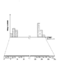
- FIG. 10 is a diagram showing an example of a histogram in the subject area.
- a histogram is a type of statistical graph that represents the distribution status of data appearance frequencies.
- the vertical axis of the histogram indicates the appearance frequency of data (image feature amount).
- the horizontal axis of the histogram represents each class of data (image feature amount).
- the divided sections of the class will be referred to as "segments”.
- the position and size of the subject area in the reference frame are specified in advance. That is, in the reference frame, the partial area 300 including the subject area is predetermined.
- the subject tracking device generates the number of appearances of the image feature amount of the partial area 300 for each segment.
- the subject tracking device divides the number of appearances of the image feature amount of each segment by the sum of the number of appearances of the image feature amount so that the sum of the appearance frequency of the image feature amount of all the segments of the partial area 300 becomes 1. .. Accordingly, the subject tracking device normalizes the number of appearances of the image feature amount of each segment to generate a histogram representing the appearance frequency of the image feature amount of the partial region 300.
- the subject tracking device defines, for example, a partial region 400 within the range in which the subject region is searched in the tracking target frame.
- the subject tracking device generates a histogram representing the appearance frequency of the image feature amount of the partial area 400.
- the subject tracking device changes the position and size of the partial region within a range in which the subject region is searched in the tracking target frame.
- the subject tracking device defines a partial area 500 in the tracking target frame.
- the subject tracking device generates a histogram representing the appearance frequency of the image feature amount of the partial area 500.
- the subject tracking device may further generate a histogram representing the appearance frequency of the image feature amount of another partial area.
- the subject tracking device derives, for each segment, a difference value between the histogram of the image feature amount of the partial area of the reference frame and the histogram of the image feature amount of the partial area of the tracking target frame.
- the subject tracking device determines, for the tracking target frame, the position and size of the partial region in which the sum of the difference values of the appearance frequency of the image feature amount for each segment (hereinafter referred to as “difference total value”) is the minimum. It is defined as the position and size (tracking result) of the subject area in.
- a method of converting a pixel value of a frame image input to a subject tracking device into a hue, saturation and luminance (HSV) format and tracking a subject area based on the hue and the saturation is a tracking due to a change in a lighting environment of the subject. It is disclosed in Non-Patent Document 1 for the purpose of preventing a decrease in accuracy (see Non-Patent Document 1). Non-Patent Document 2 discloses a method for tracking feature points of an image based on a difference between an image feature amount and an average value of image feature amounts derived in advance for the entire frame image (Non-Patent Document 2). reference).
- Non-Patent Documents 3 and 4 disclose a method of tracking a subject region based on HoG (Histograms of Oriented Gradients) feature amount, which is a strong image feature amount against changes in the illumination environment of the subject (Non-Patent Documents 3 and 4). 3 and 4).
- HoG HoG
- the subject tracking device When tracking the subject area based on the HoG feature amount, the subject tracking device generates a histogram based on the direction of the pixel gradient of the frame image.
- the histogram representing the appearance frequency of the luminance feature amount is a histogram. Changes throughout. For this reason, since the total difference value becomes large, the tracking accuracy of the subject region is reduced.
- the histogram representing the appearance frequency of the image feature amount in the orientation of the edge of the image changes in the entire histogram. For this reason, since the total difference value becomes large, the tracking accuracy of the subject region is reduced.
- the hue and the saturation in the frame image change when the color temperature is changed according to the auto white balance of the camera or when the subject is illuminated with colored light. Therefore, the tracking accuracy of the subject area is reduced.
- the feature amount of the brightness changes in a part of the frame image and the other areas in the frame image change when only the subject is illuminated by the light of the spotlight. Since the feature value of the brightness does not change, the tracking accuracy of the subject area is reduced.
- SIFT Scale-Invariant Feature Transform
- the conventional subject tracking device may not be able to improve the accuracy of tracking the subject region in the frame image of the moving image.
- an object of the present invention is to provide a subject tracking device, a subject tracking method, and a program capable of improving the accuracy of tracking a subject region in a frame image of a moving image.
- a first histogram generation unit that generates a first histogram representing the appearance frequency of the image feature amount of the subject region for each segment of the image feature amount and each auxiliary segment, and the image of the image of the candidate region
- a second histogram generation unit that generates, for each of the candidate regions, a second histogram that represents the appearance frequency of the feature amount for each of the segments of the image feature amount and for each of the auxiliary segments; and the first histogram and the second histogram.
- Difference derivation for each candidate region by comparing each segment and each auxiliary segment and deriving a difference total value that is the sum of the difference values of the appearance frequency of the image feature amount between the first histogram and the second histogram for each candidate region And a region selection unit that selects the candidate region having the smallest total difference value from the candidate regions.
- the auxiliary segment is determined so as to straddle the boundary between the segments, a subject tracking device.
- One aspect of the present invention is the subject tracking device described above, wherein the subject region is a partial region of the first frame image and the candidate region is a partial region of the second frame image.
- One aspect of the present invention is the subject tracking device described above, wherein the auxiliary segment group is defined so as to stride over all the boundaries in the region including the subject region and the candidate region.
- One aspect of the present invention is the subject tracking device described above, wherein at least one auxiliary segment is defined so as to straddle two or more of the boundaries.
- One aspect of the present invention is a subject tracking method executed by subject tracking, wherein a first histogram representing the frequency of appearance of image feature amounts in a region including a subject region is generated for each segment of the image feature amount and each auxiliary segment. Creating a second histogram for each of the candidate regions, the second histogram representing the appearance frequency of the image feature amount of the image of the candidate region for each of the segments of the image feature amount and each of the auxiliary segments; And the second histogram are compared for each segment and each auxiliary segment, and the difference total value that is the sum of the difference values of the appearance frequency of the image feature amount between the first histogram and the second histogram is the candidate. Deriving for each region, the candidate region having the smallest total difference value is treated as a candidate region. And a step of selecting from said auxiliary segment is determined so as to straddle the boundary between the segments is a subject tracking method.
- One aspect of the present invention is a program for causing a computer to function as the subject tracking device.
- FIG. 6 is a flowchart showing an operation example of the subject tracking device in the embodiment. It is a figure which shows the structural example of a histogram generation part. It is a figure which shows the example of the relationship between the array Buf of the image feature-value divided into several segments, and a histogram. 7 is a flowchart illustrating an example of histogram generation processing executed by a histogram generation unit. It is a figure which shows the structural example of the histogram production
- 5 is a diagram showing an example of a relationship between an array Buf of image feature amounts divided into a plurality of segments and a histogram in the embodiment.
- 6 is a flowchart illustrating an example of histogram generation processing in the embodiment. It is a figure which shows the example of the histogram in a to-be-photographed area
- FIG. 1 is a diagram showing a configuration example of the subject tracking device 1.
- the subject tracking device 1 is a device for tracking a subject region in a time-series frame image (moving image). Part or all of the subject tracking device 1 is realized by a processor such as a CPU (Central Processing Unit) executing a program stored in the memory.
- a processor such as a CPU (Central Processing Unit) executing a program stored in the memory.
- FIG. 2 is a diagram showing a configuration example of the subject tracking device 1 that executes a program in the embodiment.
- the subject tracking device 1 includes a processor 10, a memory 11, an input storage unit 12, a storage device 13, an output storage unit 14, an interface 15, and a bus 16.
- the processor 10 executes the program stored in the memory 11.
- the memory 11 is a volatile recording medium such as a RAM (Random Access Memory).
- the memory 11 stores the program expanded from the storage device 13.
- the input storage unit 12 is a storage unit, and stores data such as a frame image (hereinafter referred to as “input frame”) input to the subject tracking device.
- the storage device 13 is preferably a non-volatile recording medium (non-temporary recording medium) such as a flash memory or an HDD (Hard Disk Drive).
- the storage device 13 may include a volatile recording medium such as a RAM.
- the storage device 13 stores, for example, a program for causing a processor to perform a process of tracking a subject area in an input frame, a database of positions and sizes of one or more partial areas in the input frame, and a tracking result database.
- the output storage unit 14 is a storage unit that stores data such as the output tracking result (position and size of partial area).
- the interface 15 outputs the tracking result to an external device such as a predetermined network.
- the bus 16 transmits data.
- the subject tracking device 1 includes an extraction unit 101, a first histogram generation unit 102, a position / size generation unit 103, a second histogram generation unit 104, a difference derivation unit 105, a region selection unit 106, and an output unit 107.
- Each of these functional units is realized by the processor 10 executing a program stored in the memory 11.
- Part or all of the subject tracking device 1 may be realized by using hardware such as LSI (Large Scale Integration) or ASIC (Application Specific Integrated Circuit).
- the extraction unit 101 acquires a plurality of time-series frame images (image signals of moving images).
- the extraction unit 101 extracts a reference frame in which the position and size of the subject region are specified and a tracking target frame from the image signal of the moving image as input frames.
- the first histogram generation unit 102 acquires initial values of the position and size of the subject area in the reference frame.
- the first histogram generation unit 102 acquires the reference frame as an input frame.
- the first histogram generation unit 102 generates a partial area in the reference frame based on the initial values of the position and size of the partial area. That is, the first histogram generation unit 102 cuts out a partial area including the subject area from the reference frame based on the initial values of the position and size of the subject area.
- the first histogram generation unit 102 generates a histogram representing the appearance frequency of the image feature amount of the partial area in the reference frame.
- the position / size generation unit 103 acquires initial values of the position and size of the subject area in the reference frame.
- candidates for the position and size including the subject area in the tracking target frame are referred to as “candidate areas”.
- the position / size generation unit 103 includes a plurality of combinations of different positions and sizes (a group of positions and sizes, that is, a candidate group of positions and sizes, based on initial values of positions and sizes, within a range in which a subject region is searched for in a tracking target frame. A candidate area group) is generated.
- the second histogram generation unit 104 executes the same histogram generation process as the histogram generation process of the first histogram generation unit 102.
- the second histogram generation unit 104 acquires the tracking target frame from the extraction unit 101.
- the second histogram generation unit 104 acquires a position and size candidate group.
- the second histogram generation unit 104 generates a histogram of the image feature amount in the partial region of the tracking target frame according to each image feature amount of the partial region derived based on the input position and size candidates. In this way, the second histogram generation unit 104 generates a histogram of the number of position and size candidates.
- the difference deriving unit 105 compares the image feature amount histogram of the reference frame and the image feature amount histogram of the tracking target frame for each position and size candidate. That is, the difference deriving unit 105 derives the difference value (absolute value) of the appearance frequency of the image feature amount for each segment. The difference deriving unit 105 sums the difference values (histogram difference group) of the image feature amounts of the respective segments for each partial area. In this way, the difference deriving unit 105 generates the difference total value for each partial area.
- the area selection unit 106 selects a partial area having the smallest total difference value from one or more partial areas of the tracking target frame.
- the area selection unit 106 outputs the position and size of the selected partial area to the output unit 107.
- the output unit 107 outputs the position and size of the selected partial area to a prespecified output file, network, or the like.
- the output unit 107 outputs the position and size of the selected partial area to the first histogram generation unit 102 and the position / size generation unit 103.
- the region selection unit 106 can track the subject region even in the next tracking target frame based on the position and size of the partial region output to the first histogram generation unit 102 and the position / size generation unit 103. You can
- FIG. 3 is a flowchart showing an operation example of the subject tracking device 1 in the embodiment.
- the position / size generation unit 103 stores the initial values of the position and the size as the position and the size of the partial area of the reference frame (step S101).
- the subject tracking device 1 repeats the processing from step S102 to step S114 for all the tracking target frames input to the extraction unit 101 (step S102).
- the extraction unit 101 acquires a reference frame and a tracking target frame (step S103).
- the first histogram generation unit 102 acquires data on the position and size of the partial area in the reference frame (step S104).
- the first histogram generation unit 102 generates a partial area in the reference frame based on the initial values of position and size.
- the first histogram generation unit 102 generates a histogram representing the appearance frequency of the image feature amount of the partial area in the reference frame (step S105).
- the area selection unit 106 initializes the minimum value M to a predetermined large value (step S106).
- the area selection unit 106 generates a plurality of combinations of different positions and sizes (position and size candidate groups) in the range in which the object area is searched in the tracking target frame (step S107).
- the subject tracking device 1 repeats the processing from step S108 to step S113 for each of the generated position and size candidates (step S108).
- the second histogram generation unit 104 generates a partial area in the tracking target frame based on the position and size candidates.
- the second histogram generation unit 104 generates a histogram representing the appearance frequency of the image feature amount of the partial area in the tracking target frame (step S109).
- the difference derivation unit 105 compares the histogram generated by the first histogram generation unit 102 with the histogram generated by the second histogram generation unit 104, and derives the difference total value S (step S110).
- the difference deriving unit 105 compares the total difference value S with the minimum value M (step S111).
- step S111: NO When the difference total value S is equal to or larger than the minimum value M (step S111: NO), the difference deriving unit 105 advances the process to step S114.
- step S111: YES When the difference total value S is less than the minimum value M (step S111: YES), the difference deriving unit 105 substitutes the difference total value S for the minimum value M (step S112).
- step S112 The difference deriving unit 105 substitutes the position and size candidates into the variable “Result” representing the tracking result (step S113).
- the difference deriving unit 105 records the variable “Result” in the tracking result database as the initial value of the position and size of the next reference frame (step S114).
- the output unit 107 outputs the variable "Result” representing the tracking result to an output file or the like (step S115).
- FIG. 4 is a diagram showing a configuration example of the histogram generation unit 200 shown as a comparison target of the first histogram generation unit 102 and the second histogram generation unit 104 of the embodiment.
- the histogram generation unit 200 includes a feature amount conversion unit 201, a segment division unit 202, an appearance number derivation unit 203, a normalization unit 204, and a histogram output unit 205.
- the feature amount conversion unit 201 converts the pixel value of the input frame into an image feature amount of a predetermined type (for example, hue, saturation, brightness).
- the segment dividing unit 202 divides the image feature amount of the partial region derived based on the input position and size into segment groups having a predetermined interval (quantization size). That is, the segment dividing unit 202 defines segments (classes) at predetermined intervals in the image feature amount of the partial area.
- FIG. 5 is a diagram showing an example of a relationship between an array Buf of image feature amounts (classes) divided into a plurality of segments and a histogram.
- the value of the array Buf of each segment represents the appearance frequency of the image feature amount of that segment.
- the image feature amount is, for example, a feature amount of brightness of a pixel.
- the brightness is represented by a value from 0 to 255, for example.
- the offset value O of the image feature amount is 0.
- the quantization size (segment size) D is 8.
- the appearance number deriving unit 203 derives the number of appearances of the image feature amount of the partial region for each segment.
- the normalization unit 204 derives the total number of appearances of the image feature amount of each segment for the input frame.
- the normalization unit 204 executes division processing so that the sum of the appearance frequencies of the image feature amounts of all the segments of the partial area becomes 1, and normalizes the number of appearances of the image feature amount of each segment.
- the histogram output unit 205 outputs the normalized appearance frequency to the difference deriving unit as a histogram of the appearance frequency of the image feature amount for each segment.
- FIG. 6 is a flowchart showing an example of the histogram generation processing executed by the histogram generation unit 200, which is shown as a comparison target of the histogram generation processing of the embodiment.
- the feature amount conversion unit 201 converts the pixel value of the input frame into an image feature amount of a predetermined type (step S201).
- the segment dividing unit 202 generates N arrays Buf (arrays Buf [0] to Buf [N-1]) that are the number of segments (division number).
- the segment dividing unit 202 initializes the value of each element of the array Buf to 0 (step S202).
- the histogram generation unit 200 repeats the process of step S204 for each image feature amount of the partial area derived based on the input position and size candidates (step S203).
- the segment dividing unit 202 adds a predetermined offset value O to the image feature amount.
- the segment dividing unit 202 quantizes (clipping) the result obtained by dividing the offset image feature amount by the quantization size D into a quantized value from “0” to “N ⁇ 1”, for example.
- a quantized value X of the offset image feature amount is generated (step S204).
- the segment division unit 202 increments the value (the number of appearances) of the array Buf [X] by 1 (step S205).
- the appearance number deriving unit 203 derives the total value S1 of the values of the elements of the array Buf (step S206).
- the normalization unit 204 divides the value of each element of the array Buf by the total value S1 (step S207).
- the histogram output unit 205 outputs the array Buf to the difference deriving unit as a histogram of the image feature amount of the partial area of the input frame (step S208).
- FIG. 7 is a diagram illustrating a configuration example of the first histogram generation unit 102 in the embodiment.
- the configuration of the first histogram generation unit 102 and the configuration of the second histogram generation unit 104 are the same. Therefore, in FIG. 5, a configuration example of the first histogram generation unit 102 will be described.
- the first histogram generation unit 102 includes a feature amount conversion unit 301, a segment division unit 302, an auxiliary segment division unit 303, an appearance number derivation unit 304, a normalization unit 305, and a histogram output unit 306.
- the first histogram generation unit 102 further includes the auxiliary segment division unit 303 as compared with the histogram generation unit 200.
- the feature amount conversion unit 301 converts the pixel value of the input frame into an image feature amount of a predetermined type.
- the segment dividing unit 302 divides the image feature amount (signal intensity) of the partial area derived based on the input position and size candidates into segment groups at predetermined intervals (quantization size). That is, the segment dividing unit 302 sets segments (classes) at predetermined intervals in the image feature amount of the partial area.
- the auxiliary segment dividing unit 303 divides the image feature amount of the partial area derived based on the input position and size candidates into auxiliary segment groups at predetermined intervals. That is, the auxiliary segment division unit 303 sets the auxiliary classes at predetermined intervals in the image feature amount of the partial area.
- FIG. 8 is a diagram showing an example of a relationship between an array Buf of image feature amounts (classes) divided into a plurality of segments and a histogram in the embodiment.
- the value of the array Buf of each segment represents the appearance frequency of the image feature amount of that segment.
- the value of the array Buf of each auxiliary segment represents the appearance frequency of the image feature amount of the auxiliary segment.
- the image feature amount is, for example, a feature amount of color difference between pixels.
- the color difference is represented by a value from 0 to 255, for example.
- the offset value O of the image feature amount is 0.
- the quantization size (segment size) D is 8.
- an array Buf [X main ] (from Buf [0] to Buf [31] in FIG. 8) of image feature amounts of a plurality of segments in the partial area is shown.
- the offset value O of the image feature amount is 0.
- an array Buf [X sub ] (from Buf [32] to Buf [62] in FIG. 8) of image feature amounts of one or more auxiliary segments in the partial area is shown.
- the offset value O of the image feature amount is ( ⁇ D / 2).
- the quantization size (segment size) D is 8.
- the auxiliary segment group may be defined so as to straddle all the boundaries between the subject area and the candidate areas (position and size candidates). At least one auxiliary segment may be defined to cross two or more boundaries.
- the auxiliary segment dividing unit 303 divides the image feature amount of the partial region into auxiliary segment groups so that the auxiliary segment straddles at least one boundary between adjacent segments.
- the auxiliary segment division unit 303 divides the image feature amount of the partial region into auxiliary segment groups so that each auxiliary segment straddles each boundary of all segments.
- the auxiliary segment dividing unit 303 may set the auxiliary segment in the histogram so as to straddle the boundary of some segments according to the characteristics of the image feature amount. For example, a natural image has a characteristic that it is biased toward the median value of the color difference feature amounts (for example, 128 in the range from 0 to 255), and therefore, it is supplemented to the boundary (portion) of the segment where the color difference feature amount bias is large in the histogram.
- the segment may be defined.
- the auxiliary segment dividing unit 303 performs processing in comparison with the case where the auxiliary segment dividing unit 303 divides the image feature amount of the partial region into auxiliary segment groups so that each auxiliary segment straddles each boundary of all segments. The tracking accuracy can be improved without significantly reducing the speed.
- the auxiliary segment dividing unit 303 may set an auxiliary segment having a larger quantization size in the histogram. That is, the image feature amount of the partial area may be divided into auxiliary segment groups so that at least one auxiliary segment straddles two or more boundaries between the segments. As a result, the auxiliary segment division unit 303 can stably improve the tracking accuracy with respect to changes in the image feature amount. Incidentally. In order to avoid difficulty in deriving the image feature amount of the subject region when the quantization size D of the auxiliary segment is larger than the predetermined size, the auxiliary segment dividing unit 303 determines the image feature amount of the partial region according to the characteristic of the image feature amount. , Determine the quantization size of the auxiliary segment appropriately.
- the appearance number deriving unit 304 derives the appearance number of the image feature amount of the partial area for each segment and each auxiliary segment.
- the normalization unit 305 derives the total number of appearances of the feature amount of each segment for the input frame.
- the normalization unit 305 performs division processing so that the sum of the appearance frequencies of the image feature amounts of the segment and the auxiliary segment in the partial area becomes 1, and normalizes the number of appearances of the image feature amount of each segment.
- the histogram output unit 306 outputs the appearance frequency generated by normalizing the number of appearances to the difference deriving unit 105 as a histogram representing the appearance frequency of the image feature amount of each segment.
- FIG. 9 is a flowchart showing an example of histogram generation processing in the embodiment.
- the feature amount conversion unit 301 converts the pixel value of the input frame into an image feature amount of a predetermined type (step S301).
- the segment dividing unit 302 generates an array Buf (Buf [0] to Buf [A-1]) of image feature amounts of A segments, and initializes the value of each element of this array Buf to 0.
- the auxiliary segment dividing unit 303 generates an array Buf (Buf [A] to Buf [N-1]) of image feature amounts of (A-1) segments, and sets the value of each element of this array Buf to 0. (Step S302).
- the first histogram generation unit 102 and the second histogram generation unit 104 repeat the processing from step S303 to step S307 for each image feature amount of the partial area derived based on the input position and size candidates.
- the segment dividing unit 302 quantizes (clipping) the result of dividing the offset image feature amount by the quantization size D into a quantized value from “0” to “A-1”, for example,
- the quantized value Xmain of the offset image feature amount is generated (step S304).
- the segment dividing unit 302 increments the value (the number of appearances) of the array Buf [X main ] by 1 (step S305).
- the segment dividing unit 302 quantizes (clipping) the result of dividing the offset image feature amount by the quantization size D into a quantized value from “0” to “(A ⁇ 1) ⁇ 1”, for example. By doing so, the quantized value X sub of the image feature amount that has been offset is generated (step S306).
- the auxiliary segment division unit 303 increments the value (the number of appearances) of the array Buf [X sub + A] by 1 (step S307).
- the appearance number deriving unit 304 derives the total value S1 of the values of the elements of the array Buf (step S308).
- the normalization unit 305 divides the value of each element of the array Buf by the total value S1 (step S309).
- the histogram output unit 306 outputs the array Buf to the difference derivation unit 105 as a histogram of the image feature amount of the partial area of the input frame (step S310).
- the subject tracking device 1 of the embodiment includes the first histogram generation unit 102, the second histogram generation unit 104, the difference derivation unit 105, and the region selection unit 106.
- the first histogram generation unit 102 generates a first histogram that represents the appearance frequency of the image feature amount of the subject region for each segment of the image feature amount and each auxiliary segment.
- the second histogram generation unit 104 generates, for each candidate region, a second histogram that represents the appearance frequency of the image feature amount of the candidate region for each segment of the image feature amount and each auxiliary segment.
- the difference deriving unit 105 compares the first histogram and the second histogram for each segment and for each auxiliary segment, and the difference total value that is the sum of the difference values of the appearance frequency of the image feature amount between the first histogram and the second histogram. Is derived for each candidate area.
- the area selection unit 106 selects a candidate area having the smallest total difference value from the candidate areas.
- the auxiliary segment is defined so as to straddle the boundary between the segments.
- the subject tracking device 1 of the embodiment can improve the accuracy of tracking the subject region in the frame image of the moving image.
- the subject area may be a partial area of the first frame image of the moving image.
- the candidate area may be a partial area of the second frame image of the moving image.
- the subject tracking device 1 uses the histogram showing the appearance frequency of the image feature amount for each first segment and the histogram showing the appearance frequency of the image feature amount for each second segment. For and, the appearance frequencies of the image feature amounts are compared.
- the first segment is a class that divides (divides) the image feature amount at predetermined intervals.
- the second segment is an auxiliary segment defined so as to straddle the boundary between the first segments. Note that “gradually changing” means that the change in the time difference between the reference frame and the tracking target frame has an influence on the histogram, for example, one segment or less (eg, half or less of one segment). That is.
- the subject tracking device 1 can suppress an increase in the total difference value between the segments based on the second segment, it is possible to prevent the tracking accuracy from decreasing.
- the subject tracking device 1 can prevent the tracking accuracy from decreasing by only adding the second segment (auxiliary segment) to the first segment.
- the number of tracking target frames may be plural.
- the subject tracking device 1 may detect a partial area in which the sum of the differences between the histograms of the image characteristic amounts of the partial areas of the reference frame and the histograms of the image characteristic amounts of the partial areas of the plurality of tracking target frames is minimum. ..
- a plurality of subject areas may be tracked.
- the shape of the region (portion) in the input frame does not have to be rectangular, and may be any shape such as circular.
- the present invention can be applied to an image processing system.
- DESCRIPTION OF SYMBOLS 1 ... Subject tracking device, 10 ... Processor, 11 ... Memory, 12 ... Input storage part, 13 ... Storage device, 14 ... Output storage part, 15 ... Interface, 16 ... Bus, 101 ... Extraction part, 102 ... First histogram generation Part 103 ... Position / size generation unit 104 ... Second histogram generation unit 105 ... Difference derivation unit 106 ... Region selection unit 107 ... Output unit 200 ... Histogram generation unit 201 ... Feature amount conversion unit 202 ... Segment division unit, 203 ... Occurrence number derivation unit, 204 ... Normalization unit, 205 ... Histogram output unit, 300 ... Partial region, 301 ...
- Feature amount conversion unit 302 ... Segment division unit, 303 ... Auxiliary segment division unit, 304 ... Appearance number derivation unit, 305 ... Normalization unit, 306 ... Histogram output unit, 400 ... Partial region, 500 ... Partial region
Landscapes
- Engineering & Computer Science (AREA)
- Theoretical Computer Science (AREA)
- Computer Vision & Pattern Recognition (AREA)
- Multimedia (AREA)
- Physics & Mathematics (AREA)
- General Physics & Mathematics (AREA)
- Artificial Intelligence (AREA)
- Health & Medical Sciences (AREA)
- Computing Systems (AREA)
- Databases & Information Systems (AREA)
- Evolutionary Computation (AREA)
- General Health & Medical Sciences (AREA)
- Medical Informatics (AREA)
- Software Systems (AREA)
- Signal Processing (AREA)
- Studio Devices (AREA)
- Image Analysis (AREA)
Abstract
被写体追跡装置は、被写体領域の画像特徴量の出現頻度を画像特徴量のセグメントごと及び補助セグメントごとに表す第1ヒストグラムを生成する第1ヒストグラム生成部と、候補領域の画像特徴量の出現頻度を画像特徴量のセグメントごと及び補助セグメントごとに表す第2ヒストグラムを候補領域ごとに生成する第2ヒストグラム生成部と、第1ヒストグラムと第2ヒストグラムとをセグメントごと及び補助セグメントごとに比較し、第1ヒストグラムと第2ヒストグラムとの画像特徴量の出現頻度の差分合計値を候補領域ごとに導出する差分導出部と、差分合計値が最小である候補領域を各候補領域のうちから選択する領域選択部とを備える。補助セグメントは、セグメント間の境界を跨ぐように定められる。
Description
本発明は、被写体追跡装置、被写体追跡方法及びプログラムに関する。
動画像のフレーム画像内で被写体を包含する領域(以下「被写体領域」という。)を追跡する技術分野では、画像(信号強度)の特徴量のヒストグラムに基づいて被写体領域を追跡する方法がある。以下、追跡対象である被写体領域を含むフレーム画像を「追跡対象フレーム」という。追跡対象フレームから参照されるフレーム画像を「参照フレーム」という。以下、動画像のフレーム画像の一部分の領域を「部分領域」という。以下、被写体領域又は部分領域に内包される画素信号から導出される特徴量を「画像特徴量」という。
図10は、被写体領域におけるヒストグラムの例を示す図である。ヒストグラムは、データの出現頻度の分布状況を表す統計グラフの一種である。ヒストグラムの縦軸は、データ(画像特徴量)の出現頻度を示す。ヒストグラムの横軸は、データ(画像特徴量)の各階級を表す。以下、階級の分割区間を「セグメント」という。
参照フレーム内の被写体領域の位置及びサイズは、予め特定されている。すなわち、参照フレームにおいて、被写体領域を含む部分領域300は予め定められている。被写体追跡装置は、部分領域300の画像特徴量の出現数を、セグメントごとに生成する。被写体追跡装置は、部分領域300の全てのセグメントの画像特徴量の出現頻度の総和が1になるように、各セグメントの画像特徴量の出現数を、画像特徴量の出現数の総和で除算する。これにより、被写体追跡装置は、各セグメントの画像特徴量の出現数を正規化することによって、部分領域300の画像特徴量の出現頻度を表すヒストグラムを生成する。
被写体追跡装置は、追跡対象フレーム内で被写体領域が探索される範囲内に、例えば、部分領域400を定める。被写体追跡装置は、部分領域400の画像特徴量の出現頻度を表すヒストグラムを生成する。被写体追跡装置は、追跡対象フレーム内で被写体領域が探索される範囲内で、部分領域の位置及びサイズを変更する。図10では、被写体追跡装置は、追跡対象フレーム内に部分領域500を定める。被写体追跡装置は、部分領域500の画像特徴量の出現頻度を表すヒストグラムを生成する。被写体追跡装置は、他の部分領域の画像特徴量の出現頻度を表すヒストグラムを更に生成してもよい。
被写体追跡装置は、参照フレームの部分領域の画像特徴量のヒストグラムと、追跡対象フレームの部分領域の画像特徴量のヒストグラムとの間の差分値を、セグメントごとに導出する。被写体追跡装置は、追跡対象フレームについて、セグメントごとの画像特徴量の出現頻度の差分値の合計(以下「差分合計値」という。)が最小となる部分領域の位置及びサイズを、その追跡対象フレームにおける被写体領域の位置及びサイズ(追跡結果)と定める。
被写体追跡装置に入力されたフレーム画像の画素値を色相、彩度及び輝度(HSV)形式に変換し、色相及び彩度に基づいて被写体領域を追跡する方法が、被写体の照明環境の変化による追跡精度の低下を防ぐことを目的として、非特許文献1に開示されている(非特許文献1参照)。フレーム画像の全体について予め導出された画像特徴量の平均値と画像特徴量との差分に基づいて、画像の特徴点を追跡する方法が、非特許文献2に開示されている(非特許文献2参照)。
被写体の照明環境が変化しても、フレーム画像の画素勾配の方向は変わらない。被写体の照明環境の変化に対して強い画像特徴量であるHoG(Histograms of Oriented Gradients)特徴量に基づいて被写体領域を追跡する方法が、非特許文献3及び4に開示されている(非特許文献3及び4参照)。被写体追跡装置は、HoG特徴量に基づいて被写体領域を追跡する場合、フレーム画像の画素勾配の方向に基づいてヒストグラムを生成する。
P. Perez, C. Hue, J. Vermaak, and M. Gangnet,"Color-Based Probabilistic Tracking," in Proceeding of the European Conference on Computer Vision, pp.661-675, 2002.
Doi, M., Matsumoto, T., Kimachi, A., Nishi, S., & Ikoma, N."Robust Color Objects Tracking Method Against Illumination Color Change", 2014 Joint 7th International Conference on Soft Computing and Intelligent Systems (SCIS) and IEEE 15th International Symposium on Advanced Intelligent Systems (ISIS). 718-722, 2014.
Deepthi V.K.P and Mr. Mohammed Anvar P.K, "Visual TrackingUsing HOG and SVM", International Journal of Advanced Engineering Research andTechnology(IJAERT),Volume 4 Issue 5,2016.
D. G. Lowe, "Object recognition from local scaleinvariant features", Proc. of IEEE International Conference on Computer Vision (ICCV), pp.1150-1157, 1999.
しかしながら、画像特徴量のヒストグラムにおける出現頻度をフレーム画像間で比較して被写体領域を追跡する場合、フレーム画像間で被写体の照明環境が変化すると、輝度の特徴量の出現頻度を表すヒストグラムは、ヒストグラムの全体で変化する。このため、差分合計値が大きくなるので、被写体領域の追跡精度が低下する。フレーム画像間で被写体の向きが異なっている場合、画像のエッジの向きの画像特徴量の出現頻度を表すヒストグラムは、ヒストグラムの全体で変化する。このため、差分合計値が大きくなるので、被写体領域の追跡精度が低下する。
非特許文献1に開示された方法では、カメラのオートホワイトバランスに応じて色温度が変更された場合や、色付きの光で被写体が照射された場合等、フレーム画像における色相及び彩度が変化するので、被写体領域の追跡精度が低下する。非特許文献2に開示された方法では、スポットライトの光で被写体のみが照射された場合等、フレーム画像内の一部の領域では輝度の特徴量が変化し、フレーム画像内の他の領域では輝度の特徴量が変化しないので、被写体領域の追跡精度が低下する。非特許文献3及び4に開示された方法では、HoG特徴量として主に用いられるSIFT(Scale-Invariant Feature Transform)がアフィン変換の影響を受けないが、フレーム画像において奥行き方向へのパースが生じて平行性が失われた場合には、被写体領域の追跡精度が低下する。
これらのように、従来の被写体追跡装置は、動画像のフレーム画像内で被写体領域を追跡する精度を向上させることができない場合があった。
上記事情に鑑み、本発明は、動画像のフレーム画像内で被写体領域を追跡する精度を向上させることが可能である被写体追跡装置、被写体追跡方法及びプログラムを提供することを目的としている。
本発明の一態様は、被写体領域の画像特徴量の出現頻度を前記画像特徴量のセグメントごと及び補助セグメントごとに表す第1ヒストグラムを生成する第1ヒストグラム生成部と、候補領域の画像の前記画像特徴量の出現頻度を前記画像特徴量の前記セグメントごと及び前記補助セグメントごとに表す第2ヒストグラムを前記候補領域ごとに生成する第2ヒストグラム生成部と、前記第1ヒストグラムと前記第2ヒストグラムとを前記セグメントごと及び前記補助セグメントごとに比較し、前記第1ヒストグラムと前記第2ヒストグラムとの前記画像特徴量の出現頻度の差分値の合計である差分合計値を前記候補領域ごとに導出する差分導出部と、前記差分合計値が最小である前記候補領域を各前記候補領域のうちから選択する領域選択部とを備え、前記補助セグメントは、前記セグメント間の境界を跨ぐように定められる、被写体追跡装置である。
本発明の一態様は、上記の被写体追跡装置であって、前記被写体領域は、第1フレーム画像の部分領域であり、前記候補領域は、第2フレーム画像の部分領域である。
本発明の一態様は、上記の被写体追跡装置であって、前記補助セグメント群は、前記被写体領域を含む領域と前記候補領域とにおける全ての前記境界を跨ぐように定められる。
本発明の一態様は、上記の被写体追跡装置であって、少なくとも1個の前記補助セグメントは、2個以上の前記境界を跨ぐように定められる。
本発明の一態様は、被写体追跡が実行する被写体追跡方法であって、被写体領域を含む領域の画像特徴量の出現頻度を前記画像特徴量のセグメントごと及び補助セグメントごとに表す第1ヒストグラムを生成するステップと、候補領域の画像の前記画像特徴量の出現頻度を前記画像特徴量の前記セグメントごと及び前記補助セグメントごとに表す第2ヒストグラムを前記候補領域ごとに生成するステップと、前記第1ヒストグラムと前記第2ヒストグラムとを前記セグメントごと及び前記補助セグメントごとに比較し、前記第1ヒストグラムと前記第2ヒストグラムとの前記画像特徴量の出現頻度の差分値の合計である差分合計値を前記候補領域ごとに導出するステップと、前記差分合計値が最小である前記候補領域を各前記候補領域のうちから選択するステップとを有し、前記補助セグメントは、前記セグメント間の境界を跨ぐように定められる、被写体追跡方法である。
本発明の一態様は、上記の被写体追跡装置としてコンピュータを機能させるためのプログラムである。
本発明により、動画像のフレーム画像内で被写体領域を追跡する精度を向上させることが可能である。
本発明の実施形態について、図面を参照して詳細に説明する。
図1は、被写体追跡装置1の構成例を示す図である。被写体追跡装置1は、時系列のフレーム画像(動画像)内で被写体領域を追跡する装置である。被写体追跡装置1の一部又は全部は、CPU(Central Processing Unit)等のプロセッサが、メモリに記憶されたプログラムを実行することにより実現される。
図1は、被写体追跡装置1の構成例を示す図である。被写体追跡装置1は、時系列のフレーム画像(動画像)内で被写体領域を追跡する装置である。被写体追跡装置1の一部又は全部は、CPU(Central Processing Unit)等のプロセッサが、メモリに記憶されたプログラムを実行することにより実現される。
図2は、実施形態における、プログラムを実行する被写体追跡装置1の構成例を示す図である。被写体追跡装置1は、プロセッサ10と、メモリ11と、入力記憶部12と、記憶装置13と、出力記憶部14と、インタフェース15と、バス16とを備える。
プロセッサ10は、メモリ11に記憶されているプログラムを実行する。メモリ11は、RAM(Random Access Memory)などの揮発性の記録媒体である。メモリ11は、記憶装置13から展開されたプログラムを記憶する。入力記憶部12は、記憶部であり、被写体追跡装置に入力されたフレーム画像(以下「入力フレーム」という。)等のデータを記憶する。
記憶装置13は、例えば、フラッシュメモリ、HDD(Hard Disk Drive)などの不揮発性の記録媒体(非一時的な記録媒体)が好ましい。記憶装置13は、RAMなどの揮発性の記録媒体を備えてもよい。記憶装置13は、例えば、入力フレーム内で被写体領域を追跡する処理をプロセッサに実行させるためのプログラムと、入力フレーム内における1個以上の部分領域の位置及びサイズのデータベースと、追跡結果データベースとを記憶する。
出力記憶部14は、記憶部であり、出力される追跡結果(部分領域の位置及びサイズ)等のデータを記憶する。インタフェース15は、追跡結果を所定のネットワーク等の外部装置に出力する。バス16は、データを伝送する。
図1に戻り、被写体追跡装置1の構成例の説明を続ける。
被写体追跡装置1は、抽出部101と、第1ヒストグラム生成部102と、位置・サイズ生成部103と、第2ヒストグラム生成部104と、差分導出部105と、領域選択部106と、出力部107とを備える。
被写体追跡装置1は、抽出部101と、第1ヒストグラム生成部102と、位置・サイズ生成部103と、第2ヒストグラム生成部104と、差分導出部105と、領域選択部106と、出力部107とを備える。
これらの各機能部は、メモリ11に記憶されたプログラムをプロセッサ10が実行することにより実現される。なお、被写体追跡装置1の一部又は全部は、例えば、LSI(Large Scale Integration)やASIC(Application Specific Integrated Circuit)等のハードウェアを用いて実現されてもよい。
抽出部101は、時系列の複数のフレーム画像(動画像の画像信号)を取得する。抽出部101は、被写体領域の位置及びサイズが特定された参照フレームと、追跡対象フレームとを、入力フレームとして動画像の画像信号から抽出する。
第1ヒストグラム生成部102は、参照フレーム内における被写体領域の位置及びサイズの初期値を取得する。第1ヒストグラム生成部102は、参照フレームを入力フレームとして取得する。第1ヒストグラム生成部102は、部分領域の位置及びサイズの初期値に基づいて、参照フレームに部分領域を生成する。すなわち、第1ヒストグラム生成部102は、被写体領域の位置及びサイズの初期値に基づいて、被写体領域を含む部分領域を参照フレームから切り出す。第1ヒストグラム生成部102は、参照フレームにおける部分領域の画像特徴量の出現頻度を表すヒストグラムを生成する。
位置・サイズ生成部103は、参照フレームにおける被写体領域の位置及びサイズの初期値を取得する。以下、追跡対象フレームにおける被写体領域を含む位置及びサイズの候補を「候補領域」という。位置・サイズ生成部103は、追跡対象フレーム内で被写体領域が探索される範囲内に、位置及びサイズの初期値に基づいて、異なる位置及びサイズの複数の組み合わせ(位置及びサイズの候補群、すなわち候補領域群)を生成する。
第2ヒストグラム生成部104は、第1ヒストグラム生成部102のヒストグラム生成処理と同様のヒストグラム生成処理を実行する。第2ヒストグラム生成部104は、追跡対象フレームを抽出部101から取得する。第2ヒストグラム生成部104は、位置及びサイズの候補群を取得する。第2ヒストグラム生成部104は、入力された位置及びサイズの候補に基づいて導出される部分領域の各画像特徴量に応じて、追跡対象フレームの部分領域における画像特徴量のヒストグラムを生成する。このようにして、第2ヒストグラム生成部104は、位置及びサイズの候補の個数のヒストグラムを生成する。
差分導出部105は、参照フレームの画像特徴量のヒストグラムと、追跡対象フレームの画像特徴量のヒストグラムとを、位置及びサイズの候補ごとに比較する。すなわち、差分導出部105は、画像特徴量の出現頻度の差分値(絶対値)を、セグメントごとに導出する。差分導出部105は、各セグメントの画像特徴量の差分値(ヒストグラム差分群)を、部分領域ごとに合計する。このようにして、差分導出部105は、差分合計値を部分領域ごとに生成する。
領域選択部106は、追跡対象フレームの1個以上の部分領域のうちから、差分合計値が最小となる部分領域を選択する。領域選択部106は、選択された部分領域の位置及びサイズを、出力部107に出力する。
出力部107は、選択された部分領域の位置及びサイズを、予め指定された出力ファイル及びネットワーク等に出力する。出力部107は、選択された部分領域の位置及びサイズを、第1ヒストグラム生成部102と位置・サイズ生成部103とに出力する。これによって、領域選択部106は、第1ヒストグラム生成部102と位置・サイズ生成部103とに出力された部分領域の位置及びサイズに基づいて、次の追跡対象フレーム内でも被写体領域を追跡することができる。
図3は、実施形態における、被写体追跡装置1の動作例を示すフローチャートである。
位置・サイズ生成部103は、位置及びサイズの初期値を、参照フレームの部分領域の位置及びサイズとして記憶する(ステップS101)。被写体追跡装置1は、抽出部101に入力された全ての追跡対象フレームに対して、ステップS102からステップS114までの処理を繰り返す(ステップS102)。
位置・サイズ生成部103は、位置及びサイズの初期値を、参照フレームの部分領域の位置及びサイズとして記憶する(ステップS101)。被写体追跡装置1は、抽出部101に入力された全ての追跡対象フレームに対して、ステップS102からステップS114までの処理を繰り返す(ステップS102)。
抽出部101は、参照フレーム及び追跡対象フレームを取得する(ステップS103)。第1ヒストグラム生成部102は、参照フレーム内の部分領域の位置及びサイズのデータを取得する(ステップS104)。第1ヒストグラム生成部102は、位置及びサイズの初期値に基づいて、参照フレーム内に部分領域を生成する。第1ヒストグラム生成部102は、参照フレームにおける部分領域の画像特徴量の出現頻度を表すヒストグラムを生成する(ステップS105)。
領域選択部106は、予め定められた大きな値に最小値Mを初期化する(ステップS106)。領域選択部106は、追跡対象フレーム内で被写体領域が探索される範囲に、異なる位置及びサイズの複数の組み合わせ(位置及びサイズの候補群)を生成する(ステップS107)。被写体追跡装置1は、生成された位置及びサイズの候補ごとに、ステップS108からステップS113までの処理を繰り返す(ステップS108)。
第2ヒストグラム生成部104は、位置及びサイズの候補に基づいて、追跡対象フレーム内に部分領域を生成する。第2ヒストグラム生成部104は、追跡対象フレームにおける部分領域の画像特徴量の出現頻度を表すヒストグラムを生成する(ステップS109)。差分導出部105は、第1ヒストグラム生成部102によって生成されたヒストグラムと、第2ヒストグラム生成部104によって生成されたヒストグラムとを比較し、差分合計値Sを導出する(ステップS110)。差分導出部105は、差分合計値Sと最小値Mとを比較する(ステップS111)。
差分合計値Sが最小値M以上である場合(ステップS111:NO)、差分導出部105は、ステップS114に処理を進める。差分合計値Sが最小値M未満である場合(ステップS111:YES)、差分導出部105は、最小値Mに差分合計値Sを代入する(ステップS112)。差分導出部105は、位置及びサイズの候補を、追跡結果を表す変数「Result」に代入する(ステップS113)。差分導出部105は、次の参照フレームの位置及びサイズの初期値として、変数「Result」を追跡結果データベースに記録する(ステップS114)。出力部107は、追跡結果を表す変数「Result」を、出力ファイル等に出力する(ステップS115)。
次に、ヒストグラム生成処理について説明する。
図4は、実施形態の第1ヒストグラム生成部102及び第2ヒストグラム生成部104の比較対象として示された、ヒストグラム生成部200の構成例を示す図である。ヒストグラム生成部200は、特徴量変換部201と、セグメント分割部202と、出現数導出部203と、正規化部204と、ヒストグラム出力部205とを備える。
図4は、実施形態の第1ヒストグラム生成部102及び第2ヒストグラム生成部104の比較対象として示された、ヒストグラム生成部200の構成例を示す図である。ヒストグラム生成部200は、特徴量変換部201と、セグメント分割部202と、出現数導出部203と、正規化部204と、ヒストグラム出力部205とを備える。
特徴量変換部201は、入力フレームの画素値を、予め定められた種類(例えば、色相、彩度、輝度)の画像特徴量に変換する。セグメント分割部202は、入力された位置及びサイズに基づいて導出される部分領域の画像特徴量を、所定間隔(量子化サイズ)のセグメント群に分割する。すなわち、セグメント分割部202は、部分領域の画像特徴量に、所定間隔のセグメント(階級)を定める。
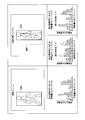
図5は、複数のセグメントに分割された画像特徴量(階級)の配列Bufとヒストグラムとの関係の例を示す図である。各セグメントの配列Bufの値は、そのセグメントの画像特徴量の出現頻度を表す。画像特徴量は、例えば、画素の輝度の特徴量である。輝度は、例えば、0から255までの値で表現される。図5では、一例として、部分領域のセグメントの個数(配列の要素の個数)Nは、32(=量子化値「0」から量子化値「31」まで)である。画像特徴量のオフセット値Oは、0である。量子化サイズ(セグメントのサイズ)Dは、8である。
図4に戻り、ヒストグラム生成部200の構成例の説明を続ける。出現数導出部203は、部分領域の画像特徴量の出現数を、セグメントごとに導出する。正規化部204は、入力フレームについて、各セグメントの画像特徴量の出現数の総和を導出する。正規化部204は、部分領域の全てのセグメントの画像特徴量の出現頻度の総和が1になるように除算処理を実行し、各セグメントの画像特徴量の出現数を正規化する。ヒストグラム出力部205は、正規化された出現頻度を、セグメントごとの画像特徴量の出現頻度のヒストグラムとして、差分導出部に出力する。
図6は、実施形態のヒストグラム生成処理の比較対象として示された、ヒストグラム生成部200が実行するヒストグラム生成処理の例を示すフローチャートである。特徴量変換部201は、入力フレームの画素値を、予め定められた種類の画像特徴量に変換する(ステップS201)。セグメント分割部202は、セグメントの個数(分割数)であるN個の配列Buf(配列Buf[0]からBuf[N-1]まで)を生成する。セグメント分割部202は、配列Bufの各要素の値0で初期化する(ステップS202)。
ヒストグラム生成部200は、入力された位置及びサイズの候補に基づいて導出される部分領域の各画像特徴量に対して、ステップS204の処理を繰り返す(ステップS203)。セグメント分割部202は、所定のオフセット値Oを画像特徴量に加算する。セグメント分割部202は、オフセットされた画像特徴量が量子化サイズDで除算された結果を、例えば、「0」から「N-1」までの量子化値に量子化(クリッピング)することによって、オフセットされた画像特徴量の量子化値Xを生成する(ステップS204)。セグメント分割部202は、配列Buf[X]の値(出現数)を1増加させる(ステップS205)。
出現数導出部203は、配列Bufの各要素の値の合計値S1を導出する(ステップS206)。正規化部204は、配列Bufの各要素の値を合計値S1で除算する(ステップS207)。ヒストグラム出力部205は、入力フレームの部分領域の画像特徴量のヒストグラムとして、配列Bufを差分導出部に出力する(ステップS208)。
図7は、実施形態における、第1ヒストグラム生成部102の構成例を示す図である。
第1ヒストグラム生成部102の構成と第2ヒストグラム生成部104の構成とは、同じである。このため図5では、第1ヒストグラム生成部102の構成例を説明する。第1ヒストグラム生成部102は、特徴量変換部301と、セグメント分割部302と、補助セグメント分割部303と、出現数導出部304と、正規化部305と、ヒストグラム出力部306とを備える。このように、第1ヒストグラム生成部102は、ヒストグラム生成部200と比較して、補助セグメント分割部303を更に備える。
第1ヒストグラム生成部102の構成と第2ヒストグラム生成部104の構成とは、同じである。このため図5では、第1ヒストグラム生成部102の構成例を説明する。第1ヒストグラム生成部102は、特徴量変換部301と、セグメント分割部302と、補助セグメント分割部303と、出現数導出部304と、正規化部305と、ヒストグラム出力部306とを備える。このように、第1ヒストグラム生成部102は、ヒストグラム生成部200と比較して、補助セグメント分割部303を更に備える。
特徴量変換部301は、入力フレームの画素値を、予め定められた種類の画像特徴量に変換する。セグメント分割部302は、入力された位置及びサイズの候補に基づいて導出される部分領域の画像特徴量(信号強度)を、所定間隔(量子化サイズ)のセグメント群に分割する。すなわち、セグメント分割部302は、部分領域の画像特徴量に、所定間隔のセグメント(階級)を定める。
補助セグメント分割部303は、入力された位置及びサイズの候補に基づいて導出される部分領域の画像特徴量を、所定間隔の補助セグメント群に分割する。すなわち、補助セグメント分割部303は、部分領域の画像特徴量に、所定間隔の補助階級を定める。
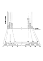
図8は、実施形態における、複数のセグメントに分割された画像特徴量(階級)の配列Bufとヒストグラムとの関係の例を示す図である。各セグメントの配列Bufの値は、そのセグメントの画像特徴量の出現頻度を表す。各補助セグメントの配列Bufの値は、その補助セグメントの画像特徴量の出現頻度を表す。画像特徴量は、例えば、画素の色差の特徴量である。色差は、例えば、0から255までの値で表現される。セグメント及び補助セグメントの合計数は、N(=2A-1)個である。図8では、一例として、部分領域のセグメント及び補助セグメントの合計数(配列の要素の個数)Nは、63(=量子化値「0」から量子化値「62」まで)である。画像特徴量のオフセット値Oは、0である。量子化サイズ(セグメントのサイズ)Dは、8である。
図8の下段には、部分領域の複数のセグメントの画像特徴量の配列Buf[Xmain](図8では、Buf[0]からBuf[31]まで)が示されている。一例として部分領域のセグメントの個数(配列の要素の個数)「A」は、32(=量子化値「0」から量子化値「31」まで)である。画像特徴量のオフセット値Oは、0である。量子化サイズ(セグメントのサイズ)Dは、8である。なお、コンピュータビジョンにおける計算用ライブラリ(OpenCV)では、8から16までの値が量子化サイズDとして広く用いられている。量子化サイズDが8である場合、セグメントの個数Aは32(=256/8)である。
図8の上段には、その部分領域の1個以上の補助セグメントの画像特徴量の配列Buf[Xsub](図8では、Buf[32]からBuf[62]まで)が示されている。一例として部分領域の補助セグメントの個数(配列の要素の個数)「A-1」は、31(=量子化値「32」から量子化値「62」まで)である。画像特徴量のオフセット値Oは、(-D/2)である。量子化サイズ(セグメントのサイズ)Dは、8である。
このように、補助セグメント群は、被写体領域と候補領域(位置及びサイズの候補)とにおける全ての境界を跨ぐように定められてもよい。少なくとも1個の補助セグメントは、2個以上の境界を跨ぐように定められてもよい。
図7に戻り、第1ヒストグラム生成部102の構成例の説明を続ける。補助セグメント分割部303は、隣り合うセグメントの少なくとも一つの境界を補助セグメントが跨ぐように、部分領域の画像特徴量を補助セグメント群に分割する。図8では、補助セグメント分割部303は、全てのセグメントの各境界を各補助セグメントが跨ぐように、部分領域の画像特徴量を補助セグメント群に分割する。
補助セグメント分割部303は、画像特徴量の特性に応じて、一部のセグメントの境界を跨ぐように、ヒストグラムに補助セグメントを定めてもよい。例えば、自然画像では色差の特徴量の中央値(例えば、0から255までの範囲の128)に偏る特性があるので、ヒストグラムにおいて色差の特徴量の偏りが大きいセグメントの境界(部分)に、補助セグメントを定めてもよい。これにより、全てのセグメントの各境界を各補助セグメントが跨ぐように補助セグメント分割部303が部分領域の画像特徴量を補助セグメント群に分割する場合と比較して、補助セグメント分割部303は、処理速度を大きく低下させることなく、追跡精度を向上させることができる。
補助セグメント分割部303は、より大きい量子化サイズの補助セグメントを、ヒストグラムに定めてもよい。すなわち、少なくとも1個の補助セグメントがセグメント間の2個以上の境界を跨ぐように、部分領域の画像特徴量を補助セグメント群に分割してもよい。これにより、補助セグメント分割部303は、画像特徴量の変化に対して安定的に追跡精度を向上させることができる。なお。補助セグメントの量子化サイズDが所定サイズよりも大きい場合に被写体領域の画像特徴量を導出することが困難にならないように、補助セグメント分割部303は、部分領域の画像特徴量の特性に応じて、補助セグメントの量子化サイズを適切に定める。
出現数導出部304は、部分領域の画像特徴量の出現数を、セグメントごと及び補助セグメントごとに導出する。正規化部305は、入力フレームについて、各セグメントの特徴量の出現数の総和を導出する。正規化部305は、部分領域におけるセグメント及び補助セグメントの画像特徴量の出現頻度の総和が1になるように除算処理を実行し、各セグメントの画像特徴量の出現数を正規化する。ヒストグラム出力部306は、出現数の正規化によって生成された出現頻度を、各セグメントの画像特徴量の出現頻度を表すヒストグラムとして、差分導出部105に出力する。
図9は、実施形態における、ヒストグラムの生成処理の例を示すフローチャートである。特徴量変換部301は、入力フレームの画素値を、予め定められた種類の画像特徴量に変換する(ステップS301)。セグメント分割部302は、A個のセグメントの画像特徴量の配列Buf(Buf[0]からBuf[A-1]まで)を生成し、この配列Bufの各要素の値を0に初期化する。補助セグメント分割部303は、(A-1)個のセグメントの画像特徴量の配列Buf(Buf[A]からBuf[N-1]まで)を生成し、この配列Bufの各要素の値を0に初期化する(ステップS302)。
第1ヒストグラム生成部102及び第2ヒストグラム生成部104は、入力された位置及びサイズの候補に基づいて導出される部分領域の各画像特徴量に対して、ステップS303からステップS307までの処理を繰り返す(ステップS303)。セグメント分割部302は、所定のオフセット値O(=0)を画像特徴量に加算する。セグメント分割部302は、オフセットされた画像特徴量が量子化サイズDで除算された結果を、例えば、「0」から「A-1」までの量子化値に量子化(クリッピング)することによって、オフセットされた画像特徴量の量子化値Xmainを生成する(ステップS304)。セグメント分割部302は、配列Buf[Xmain]の値(出現数)を1増加させる(ステップS305)。
補助セグメント分割部303は、所定のオフセット値O(=0-D/2)を画像特徴量に加算する。セグメント分割部302は、オフセットされた画像特徴量が量子化サイズDで除算された結果を、例えば、「0」から「(A-1)-1」までの量子化値に量子化(クリッピング)することによって、オフセットされた画像特徴量の量子化値Xsubを生成する(ステップS306)。補助セグメント分割部303は、配列Buf[Xsub+A]の値(出現数)を1増加させる(ステップS307)。出現数導出部304は、配列Bufの各要素の値の合計値S1を導出する(ステップS308)。正規化部305は、配列Bufの各要素の値を合計値S1で除算する(ステップS309)。ヒストグラム出力部306は、入力フレームの部分領域の画像特徴量のヒストグラムとして、配列Bufを差分導出部105に出力する(ステップS310)。
以上のように、実施形態の被写体追跡装置1は、第1ヒストグラム生成部102と、第2ヒストグラム生成部104と、差分導出部105と、領域選択部106とを備える。第1ヒストグラム生成部102は、被写体領域の画像特徴量の出現頻度を画像特徴量のセグメントごと及び補助セグメントごとに表す第1ヒストグラムを生成する。第2ヒストグラム生成部104は、候補領域の画像特徴量の出現頻度を画像特徴量のセグメントごと及び補助セグメントごとに表す第2ヒストグラムを候補領域ごとに生成する。差分導出部105は、第1ヒストグラムと第2ヒストグラムとをセグメントごと及び補助セグメントごとに比較し、第1ヒストグラムと第2ヒストグラムとの画像特徴量の出現頻度の差分値の合計である差分合計値を候補領域ごとに導出する。領域選択部106は、差分合計値が最小である候補領域を各候補領域のうちから選択する。補助セグメントは、セグメント間の境界を跨ぐように定められる。
例えば図8では、参照フレームと追跡対象フレームとの間で、1個のセグメントを表す配列Buf[0]の値が急激に変化した場合、配列Buf[0]の差分値が大きくなるので、各セグメントの差分合計値が大きくなる。配列Buf[1]の値が急激に変化した場合も同様に、各セグメントの差分合計値が大きくなる。各セグメントの差分合計値が大きい場合、被写体領域の追跡精度は低下する。これに対して、配列Buf[0]及び配列Buf[1]の境界を跨ぐように定められた1個の補助セグメントを表す配列Buf[32]の値は、配列Buf[0]の値と配列Buf[1]の値との平均値である。このため、参照フレームと追跡対象フレームとの間で配列Buf[0]又は配列Buf[1]の値が急激に変化した場合でも、配列Buf[32]の差分値があまり大きくならず、各補助セグメントの差分合計値は大きくならない。各補助セグメントの差分合計値が大きくならないので、各セグメントの差分合計値のみに基づいて被写体領域が追跡される場合と比較して、被写体領域の追跡精度の低下は抑制される。これによって、実施形態の被写体追跡装置1は、動画像のフレーム画像内で被写体領域を追跡する精度を向上させることが可能である。
被写体領域は、動画像の第1フレーム画像の部分領域でもよい。候補領域は、動画像の第2フレーム画像の部分領域でもよい。
入力フレーム内の画像が緩やかに変化する場合、被写体追跡装置1は、第1のセグメントごとの画像特徴量の出現頻度を表すヒストグラムと、第2のセグメントごとの画像特徴量の出現頻度を表すヒストグラムとについて、画像特徴量の出現頻度を比較する。第1のセグメントは、所定間隔で画像特徴量を区切る(分割する)階級である。第2のセグメントは、第1のセグメント間の境界を跨ぐように定められた補助セグメントである。なお、「緩やかに変化する」とは、参照フレームと追跡対象フレームとの時間差分における変化がヒストグラムに及ぼす影響が、例えば、1個のセグメント以下(例えば、1個のセグメントの半分以下)であることである。
被写体追跡装置1は、第2のセグメントに基づいて、セグメント間の差分合計値の増加を抑制することができるので、追跡精度の低下を防ぐことができる。被写体追跡装置1は、第1のセグメントに第2のセグメント(補助セグメント)を追加するだけで、追跡精度の低下を防ぐことができる。
以上、この発明の実施形態について図面を参照して詳述してきたが、具体的な構成はこの実施形態に限られるものではなく、この発明の要旨を逸脱しない範囲の設計等も含まれる。
例えば、追跡対象フレームの数は、複数でもよい。被写体追跡装置1は、参照フレームの部分領域の画像特徴量のヒストグラムと、複数の追跡対象フレームの部分領域の画像特徴量のヒストグラムとの差分合計値が最小となる部分領域を検出してもよい。追跡対象フレームでは、複数の被写体領域が追跡されてもよい。入力フレームにおける領域(部分)の形状は、矩形でなくてもよく、円形等の任意の形状でもよい。
本発明は、画像処理システムに適用可能である。
1…被写体追跡装置、10…プロセッサ、11…メモリ、12…入力記憶部、13…記憶装置、14…出力記憶部、15…インタフェース、16…バス、101…抽出部、102…第1ヒストグラム生成部、103…位置・サイズ生成部、104…第2ヒストグラム生成部、105…差分導出部、106…領域選択部、107…出力部、200…ヒストグラム生成部、201…特徴量変換部、202…セグメント分割部、203…出現数導出部、204…正規化部、205…ヒストグラム出力部、300…部分領域、301…特徴量変換部、302…セグメント分割部、303…補助セグメント分割部、304…出現数導出部、305…正規化部、306…ヒストグラム出力部、400…部分領域、500…部分領域
Claims (6)
- 被写体領域の画像特徴量の出現頻度を前記画像特徴量のセグメントごと及び補助セグメントごとに表す第1ヒストグラムを生成する第1ヒストグラム生成部と、
候補領域の画像の前記画像特徴量の出現頻度を前記画像特徴量の前記セグメントごと及び前記補助セグメントごとに表す第2ヒストグラムを前記候補領域ごとに生成する第2ヒストグラム生成部と、
前記第1ヒストグラムと前記第2ヒストグラムとを前記セグメントごと及び前記補助セグメントごとに比較し、前記第1ヒストグラムと前記第2ヒストグラムとの前記画像特徴量の出現頻度の差分値の合計である差分合計値を前記候補領域ごとに導出する差分導出部と、
前記差分合計値が最小である前記候補領域を各前記候補領域のうちから選択する領域選択部と
を備え、
前記補助セグメントは、前記セグメント間の境界を跨ぐように定められる、
被写体追跡装置。 - 前記被写体領域は、第1フレーム画像の部分領域であり、
前記候補領域は、第2フレーム画像の部分領域である、
請求項1に記載の被写体追跡装置。 - 前記補助セグメント群は、前記被写体領域と前記候補領域とにおける全ての前記境界を跨ぐように定められる、
請求項1又は請求項2に記載の被写体追跡装置。 - 少なくとも1個の前記補助セグメントは、2個以上の前記境界を跨ぐように定められる、
請求項3に記載の被写体追跡装置。 - 被写体追跡が実行する被写体追跡方法であって、
被写体領域の画像特徴量の出現頻度を前記画像特徴量のセグメントごと及び補助セグメントごとに表す第1ヒストグラムを生成するステップと、
候補領域の画像の前記画像特徴量の出現頻度を前記画像特徴量の前記セグメントごと及び前記補助セグメントごとに表す第2ヒストグラムを前記候補領域ごとに生成するステップと、
前記第1ヒストグラムと前記第2ヒストグラムとを前記セグメントごと及び前記補助セグメントごとに比較し、前記第1ヒストグラムと前記第2ヒストグラムとの前記画像特徴量の出現頻度の差分値の合計である差分合計値を前記候補領域ごとに導出するステップと、
前記差分合計値が最小である前記候補領域を各前記候補領域のうちから選択するステップとを有し、
前記補助セグメントは、前記セグメント間の境界を跨ぐように定められる、
被写体追跡方法。 - 請求項1から請求項4のいずれか一項に記載の被写体追跡装置としてコンピュータを機能させるためのプログラム。
Priority Applications (1)
| Application Number | Priority Date | Filing Date | Title |
|---|---|---|---|
| US17/289,203 US11763465B2 (en) | 2018-10-29 | 2019-10-07 | Object tracking apparatus, object tracking method and program |
Applications Claiming Priority (2)
| Application Number | Priority Date | Filing Date | Title |
|---|---|---|---|
| JP2018-203081 | 2018-10-29 | ||
| JP2018203081A JP2020071525A (ja) | 2018-10-29 | 2018-10-29 | 被写体追跡装置、被写体追跡方法及びプログラム |
Publications (1)
| Publication Number | Publication Date |
|---|---|
| WO2020090352A1 true WO2020090352A1 (ja) | 2020-05-07 |
Family
ID=70464000
Family Applications (1)
| Application Number | Title | Priority Date | Filing Date |
|---|---|---|---|
| PCT/JP2019/039425 Ceased WO2020090352A1 (ja) | 2018-10-29 | 2019-10-07 | 被写体追跡装置、被写体追跡方法及びプログラム |
Country Status (3)
| Country | Link |
|---|---|
| US (1) | US11763465B2 (ja) |
| JP (1) | JP2020071525A (ja) |
| WO (1) | WO2020090352A1 (ja) |
Cited By (1)
| Publication number | Priority date | Publication date | Assignee | Title |
|---|---|---|---|---|
| WO2023145177A1 (ja) * | 2022-01-26 | 2023-08-03 | 株式会社日立製作所 | 設計支援デバイス、設計支援デバイスを備える設計支援装置、及び設計支援方法 |
Citations (3)
| Publication number | Priority date | Publication date | Assignee | Title |
|---|---|---|---|---|
| JP2006227973A (ja) * | 2005-02-18 | 2006-08-31 | Kyushu Institute Of Technology | 物体追跡方法および物体追跡装置ならびにプログラム |
| JP2014112347A (ja) * | 2012-11-08 | 2014-06-19 | Nec Corp | 画像照合システム、画像照合方法、およびプログラム |
| WO2017081839A1 (ja) * | 2015-11-13 | 2017-05-18 | パナソニックIpマネジメント株式会社 | 移動体追跡方法、移動体追跡装置、およびプログラム |
-
2018
- 2018-10-29 JP JP2018203081A patent/JP2020071525A/ja active Pending
-
2019
- 2019-10-07 WO PCT/JP2019/039425 patent/WO2020090352A1/ja not_active Ceased
- 2019-10-07 US US17/289,203 patent/US11763465B2/en active Active
Patent Citations (3)
| Publication number | Priority date | Publication date | Assignee | Title |
|---|---|---|---|---|
| JP2006227973A (ja) * | 2005-02-18 | 2006-08-31 | Kyushu Institute Of Technology | 物体追跡方法および物体追跡装置ならびにプログラム |
| JP2014112347A (ja) * | 2012-11-08 | 2014-06-19 | Nec Corp | 画像照合システム、画像照合方法、およびプログラム |
| WO2017081839A1 (ja) * | 2015-11-13 | 2017-05-18 | パナソニックIpマネジメント株式会社 | 移動体追跡方法、移動体追跡装置、およびプログラム |
Cited By (3)
| Publication number | Priority date | Publication date | Assignee | Title |
|---|---|---|---|---|
| WO2023145177A1 (ja) * | 2022-01-26 | 2023-08-03 | 株式会社日立製作所 | 設計支援デバイス、設計支援デバイスを備える設計支援装置、及び設計支援方法 |
| JP2023109049A (ja) * | 2022-01-26 | 2023-08-07 | 株式会社日立製作所 | 設計支援デバイス、設計支援デバイスを備える設計支援装置、及び設計支援方法 |
| JP7615065B2 (ja) | 2022-01-26 | 2025-01-16 | 株式会社日立製作所 | 設計支援デバイス、設計支援デバイスを備える設計支援装置、及び設計支援方法 |
Also Published As
| Publication number | Publication date |
|---|---|
| JP2020071525A (ja) | 2020-05-07 |
| US11763465B2 (en) | 2023-09-19 |
| US20210398295A1 (en) | 2021-12-23 |
Similar Documents
| Publication | Publication Date | Title |
|---|---|---|
| US10303983B2 (en) | Image recognition apparatus, image recognition method, and recording medium | |
| US20210133980A1 (en) | Image processing apparatus, training apparatus, image processing method, training method, and storage medium | |
| US10970896B2 (en) | Image processing apparatus, image processing method, and storage medium | |
| US20150302566A1 (en) | Image processing device and image processing method | |
| US11176455B2 (en) | Learning data generation apparatus and learning data generation method | |
| US9430718B1 (en) | Efficient local feature descriptor filtering | |
| US20160125260A1 (en) | Selecting features from image data | |
| US10332262B2 (en) | Removal of background information from digital images | |
| JP5870598B2 (ja) | 画像のホワイトバランス処理方法及び装置 | |
| JP2016149010A (ja) | 画像評価装置、画像評価方法およびプログラム | |
| US20150227819A1 (en) | Image processing method and apparatus using trained dictionary | |
| US9870618B2 (en) | Image processing apparatus and image processing method | |
| US9305603B2 (en) | Method and apparatus for indexing a video stream | |
| US20150286892A1 (en) | Image processing apparatus and image processing method | |
| US10580127B2 (en) | Model generation apparatus, evaluation apparatus, model generation method, evaluation method, and storage medium | |
| US10643096B2 (en) | Image processing apparatus, image processing method, and non-transitory computer-readable storage medium | |
| US10509986B2 (en) | Image similarity determination apparatus and image similarity determination method | |
| Hato et al. | Fast algorithm for video shot boundary detection using surf features | |
| WO2020090352A1 (ja) | 被写体追跡装置、被写体追跡方法及びプログラム | |
| US9008434B2 (en) | Feature extraction device | |
| JP4495606B2 (ja) | 色識別装置及び色識別プログラム | |
| JP7031584B2 (ja) | 領域識別装置と領域識別方法および領域識別プログラム | |
| JP6254771B2 (ja) | 画像処理装置及び画像処理プログラム | |
| Quweider et al. | Grey level reduction for segmentation, threshholding and binarisation of images based on optimal partitioning on an interval | |
| KR101937859B1 (ko) | 360도 이미지에서의 공통 객체 탐색 시스템 및 방법 |
Legal Events
| Date | Code | Title | Description |
|---|---|---|---|
| 121 | Ep: the epo has been informed by wipo that ep was designated in this application |
Ref document number: 19879481 Country of ref document: EP Kind code of ref document: A1 |
|
| NENP | Non-entry into the national phase |
Ref country code: DE |
|
| 122 | Ep: pct application non-entry in european phase |
Ref document number: 19879481 Country of ref document: EP Kind code of ref document: A1 |