WO2020085142A1 - 計測装置及び計測システム - Google Patents
計測装置及び計測システム Download PDFInfo
- Publication number
- WO2020085142A1 WO2020085142A1 PCT/JP2019/040429 JP2019040429W WO2020085142A1 WO 2020085142 A1 WO2020085142 A1 WO 2020085142A1 JP 2019040429 W JP2019040429 W JP 2019040429W WO 2020085142 A1 WO2020085142 A1 WO 2020085142A1
- Authority
- WO
- WIPO (PCT)
- Prior art keywords
- sensor
- server
- unit
- moving
- movement
- Prior art date
- Legal status (The legal status is an assumption and is not a legal conclusion. Google has not performed a legal analysis and makes no representation as to the accuracy of the status listed.)
- Ceased
Links
Images





Classifications
-
- G—PHYSICS
- G01—MEASURING; TESTING
- G01B—MEASURING LENGTH, THICKNESS OR SIMILAR LINEAR DIMENSIONS; MEASURING ANGLES; MEASURING AREAS; MEASURING IRREGULARITIES OF SURFACES OR CONTOURS
- G01B11/00—Measuring arrangements characterised by the use of optical techniques
-
- G—PHYSICS
- G01—MEASURING; TESTING
- G01C—MEASURING DISTANCES, LEVELS OR BEARINGS; SURVEYING; NAVIGATION; GYROSCOPIC INSTRUMENTS; PHOTOGRAMMETRY OR VIDEOGRAMMETRY
- G01C3/00—Measuring distances in line of sight; Optical rangefinders
Definitions
- the present invention relates to a measuring device and a measuring system for measuring a moving locus of a moving body.
- GPS Global Positioning System
- LIDAR Light Detection and Ranging
- a wide range for example, a commercially available LIDAR has a detection range of about 30 m and a scanning range of 270 degrees
- the measurement data of LIDAR is only the position information of the measurement target expressed by the azimuth angle and distance viewed from LIDAR, there is less risk of invading the privacy of the pedestrian who is the measurement target, and resistance to recording The feeling is also small.
- Non-Patent Document 1 describes a system that performs pedestrian tracking in the environment by a plurality of lidars that detect the waist height and around.
- this system first, all the point cloud data obtained from each LIDAR is transmitted to the server. After that, the server calculates the body center points of the pedestrians, and then performs grouping on the body center points obtained from each LIDAR to determine whether or not there is a single (same) pedestrian. For a single pedestrian, the center of gravity of their body center points is calculated to obtain the position of the same pedestrian. Finally, by connecting the body center points of the same pedestrian in time series, the movement trajectory of the pedestrian is estimated (tracked).
- Non-Patent Document 1 In the measurement device described in Non-Patent Document 1, all measurement data is received at each periodic measurement in each LIDAR, the server calculates the body center point of each pedestrian in all LIDARs, and from them It is necessary to search for the same pedestrian, extract the body center point of the same pedestrian, and repeat the calculation process and the extraction process to execute the tracking process that integrates the time-series body center points. Is a big problem.
- the present invention has been made in view of the above, and provides a measuring system including a measuring device for detecting and tracking a moving body such as a pedestrian for each sensor, and a server for integrating tracking sensors. Is.
- the measuring device transmits a laser beam periodically while repeatedly scanning the scanning range, and a sensor that receives the laser beam reflected by each part of the moving body in the detection area, and from the received laser beam.
- First calculating means for calculating the position of the moving body point group corresponding to each part of the moving body, extracting the elliptical body from the calculated moving body point group, and sequentially calculating the center of gravity position of the extracted elliptical body, Out of the calculated center-of-gravity positions of the body, it is determined whether or not the distance between the center-of-gravity positions of the two bodies is less than or equal to a threshold value, and second calculating means for assigning a common ID to the body that is less than or equal to the threshold value, And a movement locus generating means for generating a movement locus by connecting the center of gravity of the body to which the common ID is attached in time series.
- the laser beam is periodically transmitted from the sensor while repeatedly scanning the scanning range, and the laser beam is reflected and received by each part of the moving body existing in the detection area. Then, the position of the moving body point group corresponding to each part of the moving body is calculated from the received laser beam by the first calculating means, the elliptical body is extracted from the calculated moving body point group, and further extracted. The barycentric position of the elliptical body is sequentially calculated. Further, the second calculating means determines whether the distance between the center of gravity positions of the two bodies in the center of gravity of the body is less than or equal to a threshold value, and a common ID is given to the body determined to be less than or equal to the threshold value. To be done.
- the measuring device can calculate the movement trajectory information from the position information acquired from its own sensor, thereby reducing the data processing load on the server side. Further, when it is determined that the distance between the center of gravity positions of the two bodies is equal to or less than the threshold value, the same moving body is appropriately detected as the same moving body even when the body is temporarily stopped (stopped). .
- the measurement system includes the measurement device arranged so that the detection ranges partially overlap with each other, and a server that acquires information on each movement locus generated by each measurement device, and the server.
- a movement locus unifying unit that extracts a pair of movement loci between the measuring devices and performs movement locus matching processing on each pair.
- the movement locus integrating means of the server extracts the pairs of movement loci between the measuring devices and performs the movement locus matching processing on each pair, the data processing load on the server is reduced. Is reduced.
- the present invention it is possible to provide a measuring device on the sensor side for reducing the data processing load on the server and a measuring system including a server to which a plurality of such measuring devices are connected.
- FIG. 6A and 6B are diagrams illustrating a laser scanning operation by a sensor
- FIG. 7A is a plan view
- FIG. 6B is a front view
- FIG. 6A and 6B are diagrams illustrating a method of detecting a person by a sensor
- FIG. 9A is a plan view illustrating detection of a human body surface by laser scanning
- FIG. 9B is a plan view illustrating a method of determining a person.
- It is an overall schematic diagram showing one embodiment of a measuring system concerning the present invention.
- It is a functional block diagram which shows one Embodiment of a server.
- FIG. 6 is a diagram illustrating a procedure of a calibration process using a common calibrator when two sensors are arranged, (A) shows a positional relationship between the first sensor and the calibrator, and (B) shows FIG. 6 is a diagram showing a positional relationship between a second sensor and a calibrator, and FIG. 9C is a diagram illustrating a method of synthesizing the results of FIGS. 9A and 9B to calibrate the positions of the two sensors.
- 6 is a flowchart showing an example of the procedure of the merge processing executed by the processor of the server, (A) shows the procedure of the merge processing I, and (B) shows the procedure of the merge processing II.
- It is a flow chart which shows an example of the procedure of the calibration processing performed by the processor of a measuring device.
- It is a flowchart which shows an example of the procedure of the process which calculates the absolute position information of each sensor performed by the processor of a server. It is a top view figure explaining the method of detecting the comings and goings accompanying a person's movement within a detection field.
- FIG. 3 is a flow chart showing a data transmission process performed by a mobile terminal carried
- (A) is a flow chart of a data transmission process I to a server showing an installation process of a combination application in the mobile terminal
- (B) is a mobile terminal after combination.
- 5 is a flowchart of a data transmission process I to a server showing an example of a process of utilizing received data from the server.
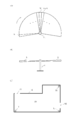
- FIG. 1A and 1B are views for explaining a laser scanning operation by a sensor.
- FIG. 1A is a plan view
- FIG. 1B is a front view
- FIG. 1C is a plan view showing an arrangement example of detection areas and sensors.
- the measurement system 1 includes at least a measurement device 10 including a sensor 11, and a server 20 that executes various data processes using transmission data from each measurement device 10. ing.
- a laser ranging scanner (LIDAR: Light Detection and Ranging) is used as the sensor 11 used in the present invention.
- the sensor 11 has a cylindrical shape and has a predetermined height, for example, about 120 cm.
- the sensor 11 horizontally transmits pulsed laser beams b1, ... bj, b (j + 1) ... From an appropriate place on the side surface on the upper side.
- the sensor 11 includes a transmitter 111 (see FIG. 4) that periodically transmits the laser beam b while scanning in the circumferential direction, and a receiver 112 (see FIG. 4) that receives a laser reflection pulse from an obstacle. It is equipped with.
- a sensor having general performance is adopted.
- the detection distance is 30 m
- the scanning range is 270 degrees
- the resolution is 0.25 degrees
- the scanning speed is 25 ms
- the distance measurement error is ⁇ 5 cm. small.
- a power source such as a secondary battery (not shown) is attached to the sensor 11, preferably built-in, so that the sensor 11 can be easily arranged at an appropriate position.
- the height of the sensor 11 is set to about 120 cm, when the laser beam b is radiated in the horizontal direction, the waist area of a general person can be detected, and the person can be identified through the shape of the body. ing.
- the irradiation direction of the laser beam b of the sensor 11 is not limited to the horizontal plane, and a three-dimensional mode in which the laser beam b is emitted with an inclination depending on the application and the detection target can be adopted.
- a plurality of sensors 11 are installed in the detection area, for example, the venue 50. It is assumed that the venue 50 has various shapes such as a circular shape and a quadrangular shape, for example, an uneven area, and the surrounding area is surrounded by a wall 51. A doorway 52 is provided in a part of the venue 50.
- the required number of sensors 11 is arranged at an appropriate position in consideration of the size and shape of the venue, the number of people, the density, and the like.
- the plurality of sensors 11 are preferably arranged in such a position and orientation that a plurality of the sensors 11 can measure the same region by partially overlapping them.
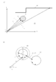
- FIG. 2A and 2B are diagrams illustrating a method of detecting a person by the sensor 11, FIG. 2A is a plan view illustrating detection of a human body surface by laser scanning, and FIG. 2B is a plan view illustrating a method of determining a person. is there.
- the laser beam b from the sensor 11 is transmitted in a certain detection direction, and to the reflection point (this is called a detection point p) on the surface of the closest object (pedestrian 6) existing in that direction.
- the distance is accurately detected based on the radio wave propagation time from transmission to reception.
- the set of rendered detection points p will be referred to as point cloud data.
- each sensor 11 has a distance d and an angle ⁇ with respect to the surface of the closest object existing on a straight line from itself at a certain time in a coordinate system having its own coordinates as the origin and the reference (front) direction as the x-axis. And are output as a set of three-dimensional vectors. That is, when the detection distance in the unit direction vector v at the time t at the i-th sensor 11 is d, the detection point information (i, t, v, d) is output to the measuring device 10.
- FIG. 2A illustrates such a relationship in a two-dimensional space. It should be noted that FIG. 2B is for explaining the conditions when detecting a pedestrian, and a detailed description will be given later.
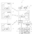
- FIG. 3 is an overall schematic diagram showing an embodiment of a measurement system according to the present invention.
- the measurement system 1 includes a plurality of measurement devices 10, a server 20, and a mobile terminal 30 that is adopted as necessary.
- the measuring device 10 includes a sensor 11 that scans the laser beam b to obtain point cloud data, and a control unit 120 that performs a certain data process on the point cloud data detected by the sensor 11.
- the server 20 includes a processing unit 21 that performs data processing, a database 22 that temporarily stores data necessary for processing, transmission data from each measuring device 10, and data in the process of being processed.
- An access point 201 for performing wireless LAN communication (for example, Wi-Fi) with the mobile terminal 30, a display device 202 for signage, and the Internet 40 are connected to the server 20.
- the ground station 41 sends and receives e-mail data including an SNS (Social Net System) between the Internet 40 and the mobile terminal 30.
- SNS Social Net System
- the mobile terminal 30 is typically a smartphone, a processor for processing data is provided inside the main body 31, and a display unit 311 is provided on the surface.
- the main body 31 generally has a built-in motion sensor 32 such as a GPS (Global Positioning System) receiver, a gyro sensor, and an acceleration sensor, and further includes a temperature sensor, a humidity sensor, an atmospheric pressure sensor, and other environmental sensors. ing.
- the gyro sensor and the acceleration sensor of the motion sensor 32 are capable of relatively detecting movement of a pedestrian carrying the mobile terminal 30, for example, movement or change in direction according to walking, or jump.
- the communication unit 33 performs data communication with the access point 201 and the ground station 41, respectively, on condition that the “HitoNavi” application described in FIG.
- the input unit 34 includes a character key group consisting of mechanical or button images, and creates a text message for electronic mail or the like through various commands and input operations.
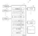
- FIG. 4 is a functional configuration diagram showing an embodiment of the measuring device 10 including the sensor 11.
- the measuring device 10 includes a sensor 11 and a measuring unit 12.
- the measuring unit 12 may be installed in the main body of the support of the sensor 11.
- the measurement unit 12 includes a control unit 120 including a processor, and the sensor 11, a program storage unit 1201 and a data storage unit 1202 are connected to the control unit 120.
- the program storage unit 1201 stores a processing program executed by the control unit 120.
- the data storage unit 1202 temporarily stores the measurement data received by the sensor 11 and also temporarily stores the data in the process.
- control unit 120 functions as the sensor driving unit 121, the measurement data acquisition unit 122, the calibration unit 123, the background processing unit 124, the person detection unit 125, the movement trajectory generation unit 126, and the communication processing unit 127. Function.
- the sensor driving unit 121 drives the transmitting unit 111 and the receiving unit 112 of the sensor 11 to emit the laser beam b as shown in FIGS. 1 (A) and 2 (A).
- the laser beam is periodically transmitted while scanning and the reflected laser beam is received.
- the measurement data acquisition unit 122 detects the distance to an obstacle by repeatedly transmitting the laser beam b in the circumferential direction as shown in FIG. In the processing, the person detection to the movement trajectory generation processing, and the calibration processing, the measurement data regarding the detection direction and the distance is acquired.
- the calibration unit 123 is executed as an initial process, and is a pre-stage process of the process of acquiring accurate absolute position information of the plurality of sensors 11 installed in the detection area, that is, the calibrator 8 ( Information acquisition processing of relative coordinates and orientation (see FIG. 6) is executed.
- the background processing unit 124 is executed as a preliminary process, and detects the wall 51 of the venue 50 shown in FIG. 1 (C).
- the detection point p is regarded as a stationary body that does not move, for example, the wall 51, and the point group data thereof is used as the background point group.
- the stationary body may include an installation object or a pillar installed in the venue 50.
- the person detection unit 125 identifies the torso of the pedestrian and the position thereof from the point cloud data.
- the human detection unit 125 derives the moving body point group by the difference of the background point groups, (II) detects the human body from the moving body point group, and (III) estimates the same person from the preceding and following frames as follows. I do.
- the point cloud data may use the reception signals detected by the sensor 11 each time, but the reception signals of a plurality of times (a plurality of scan times) are averaged in consideration of noise suppression, processing speed, and the like. It may be one.
- the human detecting section 125 first extracts an ellipse from the moving body point group. That is, when the pedestrian is assumed to be a cylinder, as shown in FIG. 2 (A), the moving body point group in which the detection directions are substantially continuous and the detection distance falls within a predetermined range is a body surface measurement point of the same pedestrian. Group as candidates for (body).
- the human detection unit 125 performs filtering based on the size of the ellipse. That is, from the moving body point group, as shown in FIG. 2B, (a) the maximum distance within the group is a constant ⁇ or less, (b) the minimum distance from the outside-group detection point is a constant ⁇ or more, (C) A group of points satisfying a certain number of detection points ⁇ or more in the group is extracted. Note that FIG. 2B is a simplified diagram for explanation, and the group 61 and the group 62 are illustrated as different groups adjacent to each other. When the above condition is not satisfied, the so-called filtering process is performed by excluding it from the detection target.
- the human detection unit 125 performs processing to make the ellipse, which is the detection target by filtering, the human body. That is, the barycentric coordinates of the body of the person in each group are calculated for each time [t- ⁇ t, t] to obtain the person coordinate point.
- the human coordinate point may be calculated by the method of calculating the center of gravity (body center point) of the ellipse, for example, geometrically calculated from the detection direction in which the detection distance d from the sensor 11 is the minimum and the detection directions in the left and right ends. The method can be adopted.
- the human detection unit 125 detects the human coordinate points detected at each time and at the detection times t, t + ⁇ t, and t ⁇ t, the general human moving speed V (m / m / s) is used to determine whether there are two human coordinate points at a distance of V * ⁇ t or less. Then, when the determination is affirmative, the person detecting unit 125 considers that a single person has moved by walking, and assigns the same person ID to those person coordinate points. Further, if the person detecting unit 125 stores the information of the person coordinate points for a plurality of cycles (frames) in the time series, it is supposed that another person intercepts the sensor 11 during that time. Even if the measurement is temporarily interrupted due to passing or the like, it is possible to generate the interrupted person coordinate point by using a general interpolation method by using the stored information.
- the movement locus generation unit 126 derives a movement locus for each person ID by connecting the person coordinate points acquired by the person detection unit 125 in time series for each person ID.
- Various data regarding the coordinate position calculated by the control unit 120 are represented by relative coordinates with the sensor 11 as a reference.
- the communication processing unit 127 exchanges data with the server 20, and in this embodiment, the information obtained by the calibration unit 123 and the movement trajectory generation unit 126 is transmitted to the server.
- FIG. 5 is a functional configuration diagram showing an embodiment of the server 20.
- the server 20 includes a processing unit 21 including a processor, and the processing unit 21 is connected to a database 22, a program storage unit 23, and a display 202.
- the database 22 stores various data acquired by the measuring device 10, and temporarily stores data in the process of processing.
- the program storage unit 23 stores a processing program executed by the processing unit 21.
- the processing unit 21 executes the movement trajectory integration unit 211, the calibration unit 212, the combination processing unit 213, the signage image creation unit 214, the mobile terminal image creation unit 215, the communication processing unit 216, and the movement monitoring unit. 217.
- the movement locus integration unit 211 performs processing for merging the movement locus data transmitted from each measuring device 10 for each single person.
- the movement locus data from each measuring device 10 may be slightly different between the same persons, and in such a case, the movement locus of one person is recognized as the movement locus of another person, or conversely, it is different. There is a possibility that the movement locus of the person will be recognized as the movement locus of the same person. Therefore, the movement locus integrating unit 211 determines whether the movement loci between the measuring devices 10 belong to the same person, and performs the integration process based on the result.
- the merge processing (i) the movement locus data of the person detected by each measuring device 10 is acquired, (ii) the movement locus data of the person is converted into absolute coordinates, and (iii) each locus pair The matching degree is calculated, and if it is equal to or more than the (iv) threshold value, it is determined to be the movement trajectory of the same person.
- the movement trajectory integration unit 211 acquires the movement trajectory data obtained by each measuring device 10 as in (ii) and considers the XY coordinates of the sensor 11. Then, it is converted into an absolute coordinate system (XY plane). Next, the position information and time information of each measuring device 10 are converted into absolute coordinates and a common time reference to standardize the coordinate system. Furthermore, the movement trajectory integration unit 211 calculates the matching degree for each trajectory pair as shown in (iii). That is, the movement locus integrating unit 211 sequentially selects pairs of movement loci to be compared in the absolute coordinate system, and for each pair, within a certain time range, a difference (distance) in position information between the pairs at the same time.
- the matching degree relating to the totaled result is obtained, and in (iv), the matching degree and the threshold value are compared. If the matching degree is equal to or more than the threshold value, it is determined that the two movement loci are obtained from the same person. And then integrate. The integration is performed, for example, by deleting one movement locus information. On the other hand, if the matching degree is less than the threshold value, it is determined that the two movement loci belong to different persons.
- the calibration unit 212 is a process for aligning the accurate relative position between the two sensors 11.
- a plurality of sensors 11 are arranged so that the detection ranges partially overlap each other. In that case, when determining whether the movement loci detected by the respective sensors 11 belong to the same person or different persons, the positions of the respective sensors 11 in the detection area and, if necessary, the same direction with a common direction. It must be set in the coordinate system.
- the calibration unit 212 performs the calibration based on the position information of the calibrator 8 acquired by the calibration unit 123 of each measuring device 10.
- the relative positional relationship is grasped by manually or mechanically matching the background points detected by each sensor 11, but the error is magnified by the manual method, and the sensor 11 of the sensor 11 by the mechanical matching method.
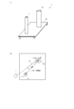
- the calibrator 8 including the two poles 81 and 82 having a specific size and positional relationship.
- FIG. 6A and 6B are diagrams showing an example of the calibrator 8, where FIG. 6A is a structural diagram and FIG. 6B is a plan view for explaining calculation of the position and orientation of the calibrator.
- the calibrator 8 has two long and columnar poles 81 and 82 which are erected in a predetermined positional relationship on the upper surface of a flat plate-like base 80, and can be integrally moved to an arbitrary position for installation. Is.
- the poles 81 and 82 reflect the laser.
- the pole 81 and the pole 82 function as two types of reflectors, and have mutually different shapes, here different radii, so that they can be distinguished.
- the calibrator 8 is not limited to a cylindrical shape, various shapes can be adopted, and it is not necessary to be divided into two pieces, and it is sufficient if the calibrators 8 have shape parts that can be distinguished from each other.
- the pre-stage process is executed by the calibration unit 123 (see FIG. 4) of the measuring device 10. That is, after the background point group is acquired as a preliminary preparation, measurement is performed by a method similar to that for detecting a moving body in a state where the sensor 11 is installed at an appropriate place in the venue 50, and the background point group is excluded, and, for example, FIG. Get a moving body point cloud like.
- the position information of the calibrator 8 is detected from the moving body point group using the same processing as the body detection method described above.
- a point group of D1 circle (181) and a point group of D2 circle (182) are detected from the moving body point group.
- the center-to-center distance L of each set of the point cloud set assumed to correspond to the D1 circle and the point cloud set assumed to correspond to the D2 circle becomes the center-to-center distance of the poles 81-82 of the calibrator 8. If they are close, consider them as D1 and D2 circles.
- the calibration unit 123 transmits the calculated distance and angle (vector) Di to the server 20.
- FIG. 7 is a diagram for explaining the procedure of the calibration process using the common calibrator 8 when the two sensors 11 and 11 ′ are arranged.
- FIG. 7A shows the first sensor 11 and the calibrator 8.
- 2B is a diagram showing the positional relationship between the second sensor 11 ′ and the calibrator 8.
- FIG. 7C is a process executed by the calibration unit 212 of the server 20. The results of (A) and (B) are combined to calibrate the positions of the two sensors 11, 11 '.
- the calibration unit 212 calculates the relative position and the absolute position of the sensor 11. First, the calibration unit 212 acquires the position information of the calibrator 8 detected by each sensor 11 at a certain time, and then uses the position of the calibrator 8 as a starting point and uses the distance and angle information with the calibrator 8 to determine a plurality of positions. The relative position of the sensor 11 is specified (see FIG. 7C).
- the calibration worker inputs and sets the position information of the absolute coordinates of any one of the sensors 11 via the input operation unit (not shown).
- the absolute coordinate system may be world coordinates or local coordinates that commonly cover the entire detection area.
- the calibration unit 212 calculates the absolute position information of the remaining sensor, that is, the sensor 11 'from the absolute position information of the sensor 11 in which the absolute coordinates are set and the relative positional relationship of the other sensors 11'.
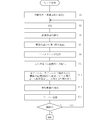
- FIG. 8 is a flowchart showing an example of a sensor processing procedure executed by the processor of the measuring device 10.
- a background point cloud acquisition process from a stationary object is executed as a preliminary process (step S1).
- the measuring device 10 is activated, and the operation of the periodic measuring process is started while scanning the laser beam b in the circumferential direction (step S3).
- the stationary body is detected along with the pedestrian. Therefore, the background point cloud is removed from the point cloud data obtained in the measurement process to detect the moving body point cloud (step S5).
- a grouping process is executed from the moving body point group to extract an ellipse for each group (step S7), and further, a filtering process for whether or not a person's ellipse size is executed (step S9).
- the group is excluded from the detection target.
- a human torso detection process that is, a process of calculating the barycentric coordinates of the human torso at each time [t- ⁇ t, t], to detect a human coordinate point is executed (step S11).
- the same person is estimated between the preceding and following frames from the positional relationship of the human coordinate points detected in the previous (t- ⁇ t) frame and the current t frame, and the person ID is assigned (step S13).
- the movement trajectory is derived, that is, the processing of joining the human coordinate points between the frames in time series is performed (step S15), and the derivation result is transmitted to the server 20 together with the person ID (step S17).
- step S19 it is determined whether or not the measurement is continued (step S19). If the measurement is continued, the process returns to step S3 and the same process is repeated. If not, this flow is ended.
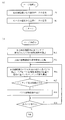
- FIG. 9 is a flowchart showing an example of the procedure of the merge processing executed by the processor of the server, (A) shows the procedure of the merge processing I, and (B) shows the procedure of the merge processing II.
- the merge process I is a process of receiving transmission data from the measuring device 10 and the mobile terminal 30 as described later. First, the transmission data is received from each measuring device 10 (step # 1), and then the transmission data from the mobile terminal 30 is received (step # 3).
- step # 11 the movement trajectory data of each person detected by each sensor 11 within a certain time range is extracted (step # 11), and the extracted movement trajectory data of each person is converted into absolute coordinates. It is converted (step # 13).
- each pair is sequentially extracted from the combination of pairs of each movement locus, and the matching degree is calculated based on the difference in position between the extracted pairs at each detection time (step # 15). Then, for the extracted pair, it is determined whether or not the calculated matching degree is equal to or higher than a threshold value (step # 17). If the calculated matching degree is equal to or higher than the threshold value, it is considered that the movement locus of the pair is the movement locus of the same person. They are integrated (step # 19). On the other hand, if no match is found, the process goes through step # 19 and is treated as a movement trajectory of another person. Next, the presence or absence of the next pair is judged (step # 21). If the next pair remains, the process returns to step # 15, the pair is extracted from the remaining pairs, and the same matching process is executed. It When the last pair ends in step # 21, this flow ends.
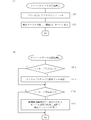
- FIG. 10 is a flowchart showing an example of the procedure of the calibration process executed by the processor of the measuring device 10.
- a background point cloud acquisition process is executed as a preliminary process (step S31).
- the calibrator 8 is placed in a detection area, for example, in an appropriate place of the venue 50 (see FIG. 7A), and in that state, the measurement device 10 is activated to periodically scan the laser beam b in the circumferential direction.
- the measurement process is started (step S33). Also in the measurement process, the stationary body is detected together with the calibrator 8. Therefore, the background point cloud is removed from the point cloud data obtained in the measurement process, and the moving body point cloud for the poles 81 and 82 of the calibrator 8 is extracted (step S35).
- the position information of the centers of the D1 and D2 circles corresponding to the poles 81 and 82 of the calibrator 8 is calculated from the moving body point group (step S37).
- the calculation of the position information for the poles 81 and 82 is performed as shown in FIG. In this way, the difference between the center-to-center distance L of the D1 and D2 circles and the center-to-center distance of the poles 81 and 82 is calculated using the position information of the D1 and D2 circles.
- the calculated position information is regarded as corresponding to the poles 181 and 182 of the calibrator 8 (step S39).
- step S41 the distance between the intermediate position Pc of the D1 and D2 circles and the sensor 11 and the angle (vector) Di in the direction connecting the center of the D2 circle from the sensor 11 are calculated (step S41), and the calculation result is It is transmitted to the server 20 (step S43).
- FIG. 11 is a flowchart showing an example of a procedure of processing for calculating absolute position information of each sensor 11 which is executed by the processor of the server 20.
- the calculation result (step S41) is received from each measuring device 10 (step # 31).
- step # 33 the calculation results detected by the respective measuring devices 10 at a certain time are read out, and based on these calculation results, the two (or a plurality of) calibrators 8 ...
- the relative positional relationship of 11 is calculated (step # 33).
- the absolute position information of a certain sensor 11 in the absolute coordinate system is manually set in the server 20 (or the input setting may be made via the measuring device 10 including the sensor 11). Step # 35).
- the calibration unit 212 calculates (conversion processing) the absolute position information of the remaining sensors 11 from the absolute position information of the sensor 11 for which the absolute position information is set and the relative positional relationship of the other sensors 11 (step # 37).
- the calculated absolute position information of each sensor 11 is stored in the database 22 and transmitted to each measuring device 10 as needed (step # 39).
- the position of each sensor 11 is defined by common coordinate information, which facilitates processing.
- the absolute position information of each sensor 11 may include orientation information.
- FIG. 12 is a plan view illustrating a method of detecting passage of a certain area, for example, entrance / exit with movement of a person in the venue 50, which is the detection area.
- the sensors 11 are installed at the upper left and lower right of the figure, and an entrance / exit 52 is provided near the center of the upper wall 51 of the figure.
- FIG. 12 exemplifies a state in which Tr1 and Tr2 are detected as the movement trajectory of the person.
- the movement monitoring unit 217 detects whether or not the integrated person's movement locus has passed a certain area, for example, whether or not the person has crossed a doorway, and further manages the number of people.
- the locus Tr1 shows the movement from left to right (t4, t3, t2, t1) near the center of the venue 50.
- the locus Tr2 detects a state (t4, t3, t2) of passing through the area of the doorway 52 from inside the venue 50. At the time of time t1, since it has moved to the outside of the detection area, it cannot be detected after the time t2.
- the pedestrian on the locus Tr2 can be detected at (t4, t3, t2) and has passed (crossed) the doorway 52 between the time t2 and the time t1, so that the pedestrian is leaving. And the number of people should be minus one.
- the sensor 11 can monitor a pedestrian moving so as to intersect (cross) a specific area in the venue 50 by detecting the entrance 52 as an entrance area (passing area) formed in a straight line in a simple manner. .
- FIG. 13 is a flow chart showing an example of the procedure of the person counting process executed by the processor of the server 20.
- the initial number i is input (step # 51). If the initial number of people is 0, no particular input is required.
- measurement is performed, a movement locus is generated, and monitoring processing is performed (step # 53).
- monitoring processing it is determined whether or not the movement locus has crossed the doorway 52 (step # 55).
- the doorway 52 is crossed “outside from inside” (Yes in step # 57)
- FIG. 14 is a diagram showing an embodiment of the arrangement of the sensor 11 that enables detection including the attribute of a person.
- another sensor 11 ′ is installed at a higher position on the wall 51, for example.
- the detection surface of the sensor 11 ' is inclined downward to enable three-dimensional detection.
- the sensor 11 ' may have a shape having a longer column, and the detection surface may be inclined downward. According to this configuration, the sensor 11 enables the person to be identified and the movement trajectory to be detected through the detection of the body, and the sensor 11 ′ to detect the head (maximum height position) of the moving person.
- the combination processing unit 213 uses the motion sensor 32 built in the mobile terminal 30 to acquire the motion of those people, and The movement track and the mobile terminal 30 are combined (the ID for linking is set). Furthermore, by visualizing the combination result, it is possible to expand the range of use and obtain new added value.
- FIG. 15 is a flow chart showing a data transmission process performed by the carried mobile terminal 30, (A) a flow chart of a data transmission process I to the server, showing a process of installing a combination application in the mobile terminal 30, (B). 6 is a flowchart of a data transmission process II to the server showing an example of a utilization process of the received data from the mobile terminal 30 after the combination.
- a QR code which is a two-dimensional bar code installed near the doorway 52, is imaged by the digital camera of the mobile terminal 30 to display the mobile image.
- the QR code registered trademark
- the QR code is analyzed by the processing unit in the terminal, the site of the corresponding URL (Uniform Resource Locator) is accessed via the ground station 41 and the Internet 40, and the "HitoNavi” application is installed.
- the "HitoNavi” application may be installed from a specific site on the Internet in advance or by communicating with the access point 201 arranged at the doorway 52.
- the “HitoNavi” application continuously reads the detection information of the motion sensor 32 built into the mobile terminal 30 and sends it to the server 20 via short-distance communication such as Wi-Fi (step ST3).
- step ST11 it is determined whether or not a message has been input from the input unit 34 (step ST11). If there is a message input, the “HitoNavi” application sends the message to the server 20 (step ST13). If no message is input, step ST13 is skipped.
- step ST15 the presence / absence of a message is determined by the “Hitobinavi” application.
- step ST17 the received message is displayed in the balloon figure on the linked mobile terminal 30 in the overhead view (step ST17), and when the message is not received, step ST17 is skipped. .
- FIG. 16 is a flowchart showing an example of a combination process performed by the combination processing unit 213 of the server 20 for the movement and movement trajectory of the mobile terminal 30 being carried.
- Motion information is periodically received from the mobile terminal 30 (step # 71), and then the commonality between the movement trajectory and the motion information is evaluated (step # 73).
- the combination processing for commonality evaluation is to evaluate whether or not the movement obtained from the movement sensor 32 and the movement trajectory of the person detected in the detection area at the same time are evaluated to determine whether or not they can be said to be the same person. To do. Whether or not there is commonality is determined (step # 75), and if there is no commonality, this flow ends. On the other hand, if there is commonality, the linking process is executed (step # 77).
- step # 79 it is determined whether SNS information has been received from the associated mobile terminal 30 (step # 79). If the SNS information is not received, this flow ends. On the other hand, when the SNS information is received, the received information from the mobile terminal 30 is processed by the signage image creation unit 214 and displayed on the signage display 202 in association with the image of the person (step # 81). Then, the information displayed on the signage display 202 is transmitted to each of the associated mobile terminals 30 (step # 83).
- FIG. 17 is a diagram of an example of a screen displayed on the display unit 311 of the mobile terminal 30 by the mobile terminal image creation unit 215.
- the venue image G50 is displayed on the screen in a bird's-eye view.
- information (temperature, humidity, noise, atmospheric pressure, surrounding congestion, etc.) obtained from other sensors or the like built in the mobile terminal 30 is tied with the ID via the access point 201, and tweet ( “Mobile device data”, in which information that the owner of the mobile device 30 is interested in or reported, such as Tweet), is transmitted to the server 20 via the ground station 41 and reflected on the screen. To be done.
- a person mark for example, an avatar image (see image G6 in FIG. 17) is displayed on the screen of the display device 202 for signage or the screen of the display unit 311 of the mobile terminal 30 in association with the position of each person.
- “Mobile terminal data” is displayed using a balloon (see image G71 in FIG. 17).
- the correct position information of each mobile terminal 30 and the “mobile terminal data” captured by the mobile terminal 30 can be collectively displayed on the venue image G50 displayed on those screens.
- the display unit 311 of the mobile terminal 30 of the person in question may be an image with a mark (see image G72) indicating the person in question.
- the movement trajectory of each person may be displayed on the display device 202 and the display unit 311 for a certain time width.
- FIG. 18 is a diagram showing an application example executed by the movement monitoring unit 217 to count the number of passengers going up and down with respect to transportation. This configuration is similar to the mode shown in FIG. 12 in which the number of people entering and leaving the venue 50 is counted. That is, FIG. 18 shows a mode in which the number of passengers on the bus is counted.
- seats SEAT are appropriately installed along the side portion B51 of the vehicle interior BU that indicates the vicinity of the rear opening / closing opening, and the door B52 is provided at the opening / closing opening so as to be openable / closable.
- the door opening / closing sensor 9 is, for example, a mechanical switch that detects opening / closing of the door B52 that slides as shown by an arrow in the drawing with a drive source (not shown).
- a plurality of sensors 11 in which the measuring unit 12 is installed may be installed, and one sensor may be installed near the door B52.
- the server 20 has the configuration of FIG. 3 and executes the same processing as the flowchart of FIG. As a result, the number of people moving up and down with respect to the vehicle interior BU can be detected, so that the number of passengers can be grasped at each time point. Further, by associating the opening / closing time and the opening time of the door B52 at each stop detected by the door opening / closing detection unit 29 of the server 20 'with the number of people moving up and down, the operation status can be grasped or reflected in the management.
- the following method can be adopted as a method of combining with a mobile terminal. That is, the position of a pedestrian who has entered the detection area, for example, the venue 50 is detected and tracked by the sensor 11.
- the server 20 issues a position information inquiry request to the mobile terminal 30 via the access point 201 on condition that the “HitoNavi” application is installed. If the entering pedestrian carries the mobile terminal 30, the pedestrian returns his / her position information to the server 20 via the access point 201 in response to the request.
- the moving path and time of the pedestrian who has entered are compared with the returned position information and time, and it can be regarded as the same position, it is determined that the mobile terminal 30 of the pedestrian has entered.
- the pedestrian can acquire the accurate movement trajectory obtained by the sensor 11 with the mobile terminal 30 via the server 20 while in the detection area.
- a method of acquiring the position of the mobile terminal 30 a method using a difference in radio field intensity from a Wi-Fi base station, a beacon positioning (BLE: Bluetooh Low Energy) method, or the like can be adopted.
- the two poles 81 and 82 which are erected on the upper surface of the base 80 are adopted, but instead of this, the base 80 and It is also possible to adopt a mode in which one pole 81 is adopted as a separate body.
- the positions on the base 80 for erecting the poles 81 in advance may be set by marking a plurality of positions, for example, two positions. Then, in the calibration process, the poles 81 are sequentially replaced at the first location and the second location, and the respective measurements are performed, so that the measurement processing at the two locations is performed as in FIG. 10.
- the pole 82 may be used or another type of pole may be used.
- the movement locus of the person is detected, but the detection target may be other than the person.
- the detection target may be other than the person.
- the measuring device transmits the laser beam periodically while repeatedly scanning the scanning range, and a sensor that receives the laser beam reflected by each part of the moving body in the detection area, A position of a moving body point group corresponding to each part of the moving body is calculated from the received laser beam, an elliptical body is extracted from the calculated moving body point group, and a barycentric position of the extracted elliptical body is sequentially calculated.
- the calculation means of No. 1 and the calculated center of gravity of the body determine whether or not the distance between the center of gravity of the two bodies is less than or equal to a threshold, and assign a common ID to the body that is less than or equal to the threshold.
- a movement locus generation means for generating a movement locus by connecting the barycentric positions of the body to which the common ID is attached in time series.
- the laser beam is periodically transmitted from the sensor while repeatedly scanning the scanning range, and the laser beam is reflected and received by each part of the moving body existing in the detection area. Then, the position of the moving body point group corresponding to each part of the moving body is calculated from the received laser beam by the first calculating means, the elliptical body is extracted from the calculated moving body point group, and further extracted. The barycentric position of the elliptical body is sequentially calculated. Further, the second calculating means determines whether the distance between the center of gravity positions of the two bodies in the center of gravity of the body is less than or equal to a threshold value, and a common ID is given to the body determined to be less than or equal to the threshold value. To be done.
- the measuring device can calculate the movement trajectory information from the position information acquired from its own sensor, thereby reducing the data processing load on the server side. Further, when it is determined that the distance between the center of gravity positions of the two bodies is equal to or less than the threshold value, the same moving body is appropriately detected as the same moving body even when the body is temporarily stopped (stopped). .
- the background processing means for calculating the position of the stationary body existing in the detection area in advance as a background point group is provided, and the first calculating means derives the moving body point group by taking a difference from the background point group. To do. With this configuration, the influence of the stationary body in the background is eliminated.
- the first calculating means performs grouping from the moving body point group using the following conditions ⁇ , ⁇ , ⁇ , and makes each group the body of the ellipse.
- the maximum distance within the group is less than or equal to a constant ⁇
- the minimum distance between the moving object points outside the group is greater than or equal to a constant ⁇
- the number of moving object points within the group is greater than or equal to a constant ⁇ . According to this configuration, it is possible to accurately detect each person.
- R is a value assumed as the maximum diameter of the body
- V is an average walking speed
- ⁇ t is a time interval in the time series. According to this configuration, the detection range for each person is set in consideration of the general walking speed of the person.
- the second calculating means interpolates the barycentric position of the broken body using the barycentric position of the body for a plurality of cycles in the time series. According to this configuration, even when another moving body crosses the sensor, it can be obtained by interpolating the position of the center of gravity therebetween.
- the measurement system includes the measurement device arranged so that the detection ranges partially overlap with each other, and a server that acquires information on each movement locus generated by each measurement device, and the server.
- a movement locus unifying unit that extracts a pair of movement loci between the measuring devices and performs movement locus matching processing on each pair.
- the movement locus integrating means of the server extracts the pairs of movement loci between the measuring devices and performs the movement locus matching processing on each pair, the data processing load on the server is reduced. Is reduced.
- a measuring system includes a calibrator having a reflector, and the measuring device detects the reflector erected at least at a first position and a second position of the calibrator by the sensor.
- the server superimposes the position and orientation of the calibrator acquired by a plurality of measuring devices in a common coordinate system, It is provided with a server side calibration means for calculating the installation position of the sensor.
- the server evaluates the commonality between the motion information from the motion sensor of the mobile terminal and the movement trajectory of the moving body, and if there is commonality, a combination process of combining the movement trajectory of the moving body and the mobile terminal. It is equipped with means. According to this configuration, since the movement trajectory of the person detected by the sensor and the mobile terminal carried by the person are combined, it becomes possible to associate information from the mobile terminal with the movement trajectory, and effective use of information Can be achieved.
- the server is also characterized in that the server is provided with movement monitoring means for detecting whether or not the movement locus of the moving body has passed a specific area within the detection area. According to this configuration, if a specific area is defined to be detectable in the detection area, it is possible to monitor the passing state of the moving body in the specific area.
- the movement monitoring means monitors the number of passengers getting on and off the bus across the elevating area. According to this configuration, when the elevating and lowering area of the bus is set as the specific area, it is possible to monitor the number of people getting on and off the bus, and thus the number of people getting on and off.
- Measuring System 8 Calibrator 10 Measuring Device 11, 11 ′ Sensor 120 Control Unit 123 Calibration Unit (Device-side Calibration Means) 124 background processing unit (background processing means) 125 person detecting section (first calculating means, second calculating means) 126 Movement Trajectory Generation Unit (Movement Trajectory Generation Means) 20 server 21 processing unit 211 moving locus integrating unit (moving locus integrating means) 212 calibration unit (server side calibration means) 213 combination processing unit (combination processing means) 217 Movement monitoring unit (movement monitoring means) 30 mobile terminal 52 entrance / exit BU interior of car
Landscapes
- Physics & Mathematics (AREA)
- General Physics & Mathematics (AREA)
- Electromagnetism (AREA)
- Engineering & Computer Science (AREA)
- Radar, Positioning & Navigation (AREA)
- Remote Sensing (AREA)
- Length Measuring Devices By Optical Means (AREA)
- Measurement Of Optical Distance (AREA)
- Traffic Control Systems (AREA)
Abstract
計測装置(10)は、走査範囲内を繰り返し走査しながら周期的にレーザビームを送信すると共に、探知領域内の動体の各部で反射したレーザビームを受信するセンサ(11)と、受信したレーザビームから動体の各部に対応した動体点群の位置を算出し、算出した動体点群から楕円の胴体を抽出し、抽出した楕円の胴体の重心位置を順次算出する人検出部(125)と、算出した胴体の重心位置のうち、2つの胴体の重心位置の間の距離が閾値以下かどうかを判定し、閾値以下とされる胴体に対して共通IDを付す人検出部(125)と、共通IDが付された胴体の重心位置を時系列につなぎ合わせて移動軌跡を生成する移動軌跡生成部(126)とを備えた。これにより、サーバでのデータ処理負担の低減に供するセンサ側の計測装置を提供する。
Description
本発明は、動体の移動軌跡を計測する計測装置及び計測システムに関する。
センサ技術の発展に伴い、人の行動データに基づく次世代システムが高い注目を集めている。特に屋内外の大規模イベント、遊園地やテーマパーク、オフィスや商業施設等、屋内外空間を歩き回る人々の位置情報は、群衆の移動履歴情報に基づくマーケティング調査、スマートホームやスマートビルディングといったエネルギー管理システム、テーマパークや商業施設や博物館・美術館等におけるパーソナルナビゲーション等、多くのサービスへの応用が期待されている。スマートフォンをはじめとするモバイル端末の測位技術としては、GPS(Global PositioningSystem)が広く利用されているが、地下や屋内では衛星からの電波を受信することができず、またスマートフォンを携行していない人々の位置や移動軌跡を得ることができない。屋内向けには、カメラ、RFID(Radio FrequencyIDentification)タグ、またモバイル端末に搭載された加速度センサやジャイセンサを用いる方法等が提案されているが、いずれの方法もプライバシ、計測領域サイズ、精度等の点で課題がある。
これらに対し、レーザ測距スキャナ(LIDAR:Light Detection and Ranging)による歩行者の計測が注目を集めている。LIDARは、周囲の物体までの距離を正確に計測することができるため、広範囲(例えば市販されているLIDARの検知範囲は30m程度、走査範囲は270度である。)を高速にスキャンすることが可能である。LIDARの計測データはLIDARから見た方位角と距離とで表される計測対象の位置情報のみであるため、計測対象となる歩行者のプライバシを侵害するおそれが少なく、記録されることへの抵抗感も小さい。
非特許文献1には、腰の高さ辺りを検知する複数のLIDARによって環境内の歩行者トラッキングを行うシステムが記載されている。このシステムでは、まず、各LIDARから得られた全ての点群データがサーバに送信される。以降、サーバは、歩行者の体中心点の算出を行い、次いで、各LIDARから得られた体中心点に対してグループ化を行って、単一の(同一)歩行者か否かを判断し、単一の歩行者については、それらの体中心点の重心を算出して同一歩行者の位置を得る。最後に、同一歩行者の体中心点を時系列でつなげることで、歩行者の移動軌跡を推定する(トラッキングする)ようにしている。
高藤巧,藤田和久,樋口雄大,廣森聡仁,山口弘純,東野輝夫,下條真司,トラッキングスキャナとモーションセンサを用いた高精度屋内位置推定手法の提案,情報処理学会論文誌 Vol.57 No.1 353-365(Jan.2016)
非特許文献1に記載の計測装置では、各LIDARでの周期的な計測の毎に全ての計測データを受信し、サーバで、全てのLIDARで各歩行者の体中心点を算出し、それらから同一歩行者を捜してその体中心点を抽出し、さらにかかる算出処理及び抽出処理を繰り返し行うことで、時系列の体中心点を統合するトラッキング処理を実行する必要があり、サーバにおけるデータ処理負担が大きいといった問題がある。
本発明は、上記に鑑みてなされたもので、センサ毎に歩行者等の動体の検出及びトラッキングを行う計測装置を、さらにトラッキングのセンサ間の統合を行うサーバを備えた計測システムを提供するものである。
本発明に係る計測装置は、走査範囲内を繰り返し走査しながら周期的にレーザビームを送信すると共に、探知領域内の動体の各部で反射したレーザビームを受信するセンサと、受信した前記レーザビームから前記動体の各部に対応した動体点群の位置を算出し、算出した前記動体点群から楕円の胴体を抽出し、抽出した前記楕円の胴体の重心位置を順次算出する第1の算出手段と、算出した前記胴体の重心位置のうち、2つの胴体の重心位置の間の距離が閾値以下かどうかを判定し、閾値以下とされた胴体に対して共通IDを付す第2の算出手段と、前記共通IDが付された前記胴体の重心位置を時系列につなぎ合わせて移動軌跡を生成する移動軌跡生成手段とを備えたものである。
本発明によれば、走査範囲内を繰り返し走査しながら周期的にセンサからレーザビームが送信され、レーザビームは探知領域内に存在する動体の各部で反射して受信される。そして、第1の算出手段によって、受信した前記レーザビームから前記動体の各部に対応した動体点群の位置が算出され、算出された前記動体点群から楕円の胴体が抽出され、さらに抽出された前記楕円の胴体の重心位置が順次算出される。さらに、第2の算出手段によって、前記胴体の重心位置のうち、2つの胴体の重心位置の間の距離が閾値以下かどうかが判定され、閾値以下と判定される胴体に対して共通IDが付与される。そして、移動軌跡生成手段によって、前記共通IDが付与された前記胴体の重心位置が時系列につなぎ合わされる。従って、計測装置は、自己のセンサから取得された位置情報から移動軌跡情報を算出するようにし、これによってサーバ側のデータ処理負担の低減に供することが可能となる。また、2つの胴体の重心位置の間の距離が閾値以下と判定された場合に、同一の動体とすることで、一時的に静止する(立ち止まる)ような状態でも同一動体として適正に検知される。
また、本発明に係る計測システムは、検知範囲が一部重なるように配置された前記計測装置と、前記各計測装置で生成された前記各移動軌跡の情報を取得するサーバとを備え、前記サーバは、前記計測装置間における移動軌跡のペアを抽出し、各ペアに対して移動軌跡のマッチング処理を行う移動軌跡統合手段を備えたものである。
本発明によれば、サーバの移動軌跡統合手段によって、前記計測装置間における移動軌跡のペアを抽出し、各ペアに対して移動軌跡のマッチング処理を行うだけとしたので、サーバでのデータ処理負担が低減する。
本発明によれば、サーバでのデータ処理負担の低減に供するセンサ側の計測装置の提供、及びかかる計測装置が複数接続されたサーバから構成される計測システムを提供できる。
図1は、センサによるレーザスキャン動作を説明する図で、(A)は平面図、(B)は正面図、(C)は探知領域とセンサの配置例を示す平面図である。本発明に係る計測システム1は、図3に示すように、センサ11を備えた計測装置10と、各計測装置10からの送信データを用いて各種のデータ処理を実行するサーバ20とを少なくとも備えている。
本発明で採用されるセンサ11として、本実施形態では、レーザ測距スキャナ(LIDAR:Light Detection and Ranging)を採用している。センサ11は、円柱形状で、所定の、例えば120cm程度の高さを有する。センサ11は、上部側の側面適所からパルス状のレーザビームb1,…bj,b(j+1) …を水平方向に送信する。センサ11は、周方向にスキャンしながら周期的にレーザビームbの送信を行う送信部111(図4参照)と、障害物からのレーザ反射パルスを受信する受信部112(図4参照)とを備えて構成されている。センサ11としては一般的な性能を有するものを採用しており、例えば、探知距離が30m、走査範囲が270度、分解能が0.25度、スキャン速度が25msで、測距誤差は±5cmと小さい。なお、センサ11には、図略の二次電池等の電源が装着、好ましくは内蔵され、適宜の位置への配置を容易にしている。センサ11の高さを120cm程度とすることで、レーザビームbを水平方向に放射した場合、一般的な人の腰辺りを検知することができ、胴体の形状を介して人の識別を可能にしている。なお、センサ11のレーザビームbの照射方向は水平面に限らず、用途、探知対象に応じて傾斜を有して放射する3次元態様を採用することができる。
図1(C)に示すように、センサ11は、探知領域である、例えば会場50に複数台設置される。会場50は、円形、四角形の場合の他、種々の形状、例えば凸凹のある領域の場合も想定され、周囲は壁51で囲われているとする。会場50の一部には出入り口52を有する。センサ11は、会場のサイズや形状、また対象となる人数、密度等を考慮して所要数が適宜の位置に配置される。複数のセンサ11は、好ましくは複数台が同一領域を一部重ねて計測できるような位置、向きで配置される。
図2は、センサ11による人検知の方法を説明する図で、(A)はレーザスキャンによる人体表面の検知を説明する平面図、(B)は人の判定方法を説明する平面視の図である。図2(A)において、センサ11からのレーザビームbがある検出方向に送信され、その方向に存在する最も近い物体(歩行者6)の表面の反射点(これを検出点pと言う)への距離を、送信時から受信時までの電波伝搬時間に基づいて正確に検知する。演出された検出点pの集合を以下、点群データという。
従って、各センサ11は、自身の座標を原点、基準(正面)方向をx軸とする座標系において、ある時刻における自身からの直線上に存在する最も近い物体の表面までの距離dと角度θとを3次元ベクトルの集合として出力する。すなわち、i番目のセンサ11での時刻tにおける単位方向ベクトルvにおける検出距離をdとしたとき、検出点情報(i, t, v, d)を計測装置10に出力する。図2(A)は、2次元空間でのかかる関係を図示したものである。なお、図2(B)は、歩行者を検出する場合の条件を説明するためのもので、詳細な説明は後述する。
図3は、本発明に係る計測システムの一実施形態を示す全体概要図である。計測システム1は、複数の計測装置10、サーバ20、及び必要に応じて採用されるモバイル端末30を備えている。計測装置10は、レーザビームbをスキャンして点群データを取得するセンサ11とセンサ11で検知した点群データに対して一定のデータ処理を施す制御部120とを備えている。サーバ20は、データ処理を行う処理部21、処理に必要なデータ類、各計測装置10からの送信データ及び処理途中のデータを一時的に記憶するデータベース22を備えている。サーバ20には、モバイル端末30と無線LAN通信(例えばWi-Fi等)を行うためのアクセスポイント201、サイネージ用の表示器202、インターネット40が接続されている。地上局41は、インターネット40とモバイル端末30との間で、SNS(Social Net System)を含む電子メールデータを送受信するものである。
なお、モバイル端末30は、典型的にはスマートフォンで、本体31の内部にはデータを処理するプロセッサが設けられ、表面には表示部311が備えられている。また、本体31は、一般的には、GPS(Global PositioningSystem)受信機、ジャイロセンサ、加速度センサ等の動きセンサ32を内蔵し、さらに、温度センサ、湿度センサ、気圧センサ、その他の環境センサを備えている。動きセンサ32のうちジャイロセンサ及び加速度センサは、モバイル端末30を所持している歩行者の移動、例えば歩行に応じた動きや方向変化、ジャンプなどを相対的に検知可能とするものである。通信部33は、図15(A)において説明する「ひとなび」アプリケーションがインストールされたことを条件に、アクセスポイント201、また地上局41との間のデータ通信をそれぞれ行う。入力部34は、機械的あるいはボタン画像からなる文字キー群を含み、種々の指示の他、入力操作を通して、電子メール用等の文章メッセージの作成を行う。
図4は、センサ11を含む計測装置10の一実施形態を示す機能構成図である。計測装置10は、センサ11及び計測部12を備えている。計測部12は、センサ11の支柱本体に内装される形態であってもよい。計測部12は、プロセッサを備える制御部120を備え、制御部120には、センサ11、プログラム記憶部1201及びデータ記憶部1202が接続されている。プログラム記憶部1201は、制御部120が実行する処理プログラムを記憶するものである。データ記憶部1202は、センサ11で受信した計測データを一時的に記憶し、また処理途中のデータを一時的に記憶するものである。
制御部120は、処理プログラムを実行することで、センサ駆動部121、計測データ取得部122、キャリブレーション部123、背景処理部124、人検出部125、移動軌跡生成部126及び通信処理部127として機能する。
センサ駆動部121は、センサ11への起動指示を受けて、センサ11の送信部111、受信部112を駆動させ、図1(A)及び図2(A)に示すような、レーザビームbをスキャンさせつつ周期的に送信し、反射してきたレーザビームの受信を行う。
計測データ取得部122は、図1(A)に示すようにレーザビームbを周方向に走査しながら繰り返し送信することによって障害物までの距離を探知するもので、背景点群の取得等の事前処理、人検出~移動軌跡生成処理、及びキャリブレーション処理において、検知方向、距離に関する計測データの取得を行う。
キャリブレーション部123は、初期処理として実行するもので、探知領域内に設置される複数のセンサ11の正確な絶対位置情報を取得する処理の内の前段処理、すなわち各センサ11でのキャリブレータ8(図6参照)の相対座標、向きの情報取得処理を実行する。
背景処理部124は、事前処理として実行するもので、図1(C)に示す会場50の壁51の検出を行うものである。同一検知方向に対して、所定の長時間、検知距離が同一である場合には、当該検出点pは、移動しない静止体、例えば壁51と見なして、それらの点群データを背景点群として事前に登録する。なお、静止体には、会場50内に設置された設置物や柱を含めることができる。
人検出部125は、点群データから歩行者の胴体の特定、及びその位置を検出する。人検出部125は、以下のように、(I)背景点群の差分による動体点群の導出、(II)動体点群から人の胴体の検出、(III)前後フレームからの同一人物の推定を行う。なお、点群データは、センサ11で検出した受信信号をその都度用いてもよいが、ノイズ抑制、処理速度等を考慮して、複数回(複数のスキャン回数分)の受信信号を平均化したものとしてもよい。例えば、同一方向からの連続して8回のスキャン分の受信信号を平均したもの、すなわち200ms(=Δt:25ms×8)周期の点群データで処理してもよい。
(I)背景点群の差分による動体点群の導出
各時刻tと十分短い時間Δt(例えば200ms)に対し、[t-Δt, t]に検出された動体点群について、それらの鉛直方向座標(Z座標)を削除したXY座標を得る。これに対し、背景処理部124で取得し、登録されている背景点とみなした点群からZ座標を削除したものと比較し、XY座標が一致すると見なされる点群を削除する。この削除処理を経て残ったものを動体点群と呼ぶ。
各時刻tと十分短い時間Δt(例えば200ms)に対し、[t-Δt, t]に検出された動体点群について、それらの鉛直方向座標(Z座標)を削除したXY座標を得る。これに対し、背景処理部124で取得し、登録されている背景点とみなした点群からZ座標を削除したものと比較し、XY座標が一致すると見なされる点群を削除する。この削除処理を経て残ったものを動体点群と呼ぶ。
(II)動体点群から人の胴体の検出
人検出部125は、まず、動体点群からの楕円形抽出を行う。すなわち、歩行者を円柱と想定した場合に、図2(A)に示すように、検知方向が実質連続し、かつ検知距離が所定範囲に収まる動体点群を、同一歩行者の体表計測点(胴体)の候補としてグループ化する。
人検出部125は、まず、動体点群からの楕円形抽出を行う。すなわち、歩行者を円柱と想定した場合に、図2(A)に示すように、検知方向が実質連続し、かつ検知距離が所定範囲に収まる動体点群を、同一歩行者の体表計測点(胴体)の候補としてグループ化する。
次いで、人検出部125は、楕円形のサイズによるフィルタリングを行う。すなわち、動体点群の中から、図2(B)に示すような、(a)グループ内の最大距離がある定数α以下、(b)グループ外検出点との最小距離がある定数β以上、(c)グループ内の検出点数がある定数γ以上、を満たす点のグループを抽出する。なお、図2(B)は、説明のための簡略化した図であり、グループ61とグループ62とが互いに隣接した別のグループとして例示されている。上記条件を満たさない場合、検出対象から外すなどして、いわゆるフィルタリング処理を行う。また、グループ内の動体点群データから楕円形状を算出し、そのサイズ、例えば楕円直径(長短軸のいずれ側でもよい)を算出する。人検出部125は、算出した楕円直径が予め設定された人体の最大直径をR(一般にはR=60cm程度)を超えている場合には、人とは判定せず、検出対象から外すなどして、いわゆるフィルタリング処理を行う。
なお、フィルタリングにおいては以下の内容が条件に反映される。すなわち、人体の最大直径をR(一般にはR=60cm程度)、人の一般的な歩行速度をVとするとき、α=R+V*Δtとなる。また、人はそれぞれパーソナルスペース(おおよそ30cm程度)を有しており、また歩き易さのため周辺の人とは一定距離を保ちながら歩行する。その距離をS(Sは経験的に50cm程度)とすれば、β=Sである(図2(B)参照)。また、人の検出点数は、センサ11と人との距離に依存する(センサ11は放射状に検出を行うため、人との距離が近い程、検出点が多くなる)。一般に、検出ステップ角度θのセンサ11から距離dに存在する人を、直径Rの円柱とみなせば、その人の検出点数は、|2* arc cos (d+R) / θ|で得られる。なお、センサ11の位置座標誤差や測距誤差から生じる検出距離の最大誤差をεとすれば、α=R+V*Δt+2ε,β=S―2εとすればよい。
次いで、人検出部125は、フィルタリングで検出対象とされた楕円形を人の胴体とする処理を行う。すなわち、グループ毎における人の胴体の重心座標を時刻[t-Δt, t]毎に算出して人座標点を得る。人座標点は、楕円の重心(体中心点)を算出する方法でよく、例えば、センサ11からの検知距離dが最小となる検知方向と、左右両端となる検知方向とから幾何学的に算出する方法が採用可能である。
(III)前後フレームから同一人物を推定
人検出部125は、時刻毎に検出した人座標点に対し、検出時刻t,t+Δt、およびt‐Δtにおいて、一般的な人間の移動速度V(m/s)を用いて、V*Δt以下の距離に2つの人座標点が存在するかどうかを判定する。そして、人検出部125は、前記判定が肯定された場合、それらは単一の人物が歩行により移動したものとみなし、それらの人座標点に同一の人物IDを割り当てる。また、人検出部125は、前記時系列における複数の周期(フレーム)分の人座標点の情報を保管しておくようにすれば、仮に、その間に、他の人がセンサ11を遮るように通過したなどの理由によって計測が一時的に途切れたとしても、保管している前記情報を用いることで途切れた人座標点を一般的な補間方式を用いて生成ことが可能となる。
人検出部125は、時刻毎に検出した人座標点に対し、検出時刻t,t+Δt、およびt‐Δtにおいて、一般的な人間の移動速度V(m/s)を用いて、V*Δt以下の距離に2つの人座標点が存在するかどうかを判定する。そして、人検出部125は、前記判定が肯定された場合、それらは単一の人物が歩行により移動したものとみなし、それらの人座標点に同一の人物IDを割り当てる。また、人検出部125は、前記時系列における複数の周期(フレーム)分の人座標点の情報を保管しておくようにすれば、仮に、その間に、他の人がセンサ11を遮るように通過したなどの理由によって計測が一時的に途切れたとしても、保管している前記情報を用いることで途切れた人座標点を一般的な補間方式を用いて生成ことが可能となる。
移動軌跡生成部126は、人検出部125で取得された人座標点を人物ID毎に時系列につなぎ合わせることで人物ID毎の移動軌跡を導出する。なお、制御部120で算出された座標位置に関する各種のデータは、センサ11を基準とした相対座標で表されたものである。
通信処理部127は、サーバ20との間でデータ授受を行うもので、本実施形態では、キャリブレーション部123、移動軌跡生成部126で得られた情報がサーバに送信される。
図5は、サーバ20の一実施形態を示す機能構成図である。サーバ20は、プロセッサを備える処理部21を備え、処理部21には、データベース22、プログラム記憶部23及び表示器202が接続されている。データベース22は、計測装置10で取得された各種のデータを記憶し、また処理途中のデータを一時的に記憶するものである。プログラム記憶部23は、処理部21が実行する処理プログラムを記憶するものである。
処理部21は、処理プログラムを実行することで、移動軌跡統合部211、キャリブレーション部212、組み合わせ処理部213、サイネージ画像作成部214、モバイル端末画像作成部215、通信処理部216及び移動監視部217として機能する。
移動軌跡統合部211は、各計測装置10から送信された移動軌跡データを単一人物毎に統合(マージ)する処理を行う。各計測装置10からの移動軌跡データは、同一人物間においても多少ずれている可能性があり、そのような場合には一人の移動軌跡が別の人物の移動軌跡として認識され、あるいは逆に別の人物の移動軌跡が同一人の移動軌跡として認識される可能性がある。そこで、移動軌跡統合部211は、各計測装置10間の移動軌跡が同一人物のものかどうかを判定し、その結果に基づいて統合処理を行うようにしている。
ここに、統合(マージ)処理は、(i)各計測装置10で検出した人物の移動軌跡データを取得し、(ii)人物の移動軌跡データを絶対座標に変換し、(iii)各軌跡ペアについて、マッチング度を算出し、(iv)閾値以上であれば、同一人物の移動軌跡と判断する手順で行われる。
すなわち、より詳細には、移動軌跡統合部211は、(i)の処理後、(ii)のように、各計測装置10で得られた移動軌跡データを取得し、センサ11のXY座標を考慮して絶対座標系(XY平面)に変換する。次いで、各計測装置10の位置情報、時刻情報を絶対座標、共通の時間基準に変換して座標系を共通化する。さらに、移動軌跡統合部211は、(iii)のように、各軌跡ペアについて、マッチング度の算出を行う。すなわち、移動軌跡統合部211は、絶対座標系において、比較対象の移動軌跡のペアを順次選定し、ペア毎に、ある時刻範囲内で、同一時刻毎のペア間の位置情報の差分(距離)を集計し、その集計結果に関するマッチング度を求め、(iv)において、マッチング度と閾値とを比較し、マッチング度が閾値以上であれば、2つの移動軌跡は同一人物から得られたものと判断して、統合する。統合は、例えば一方の移動軌跡情報を削除することで行われる。一方、マッチング度が閾値未満であれば、2つの移動軌跡は別の人物のものと判断する。
キャリブレーション部212は、2つのセンサ11間の正確な相対位置を合わせるための処理である。探知領域には、探知範囲が互いに一部重なるようにセンサ11が複数配置されることが好ましい。その場合に、各センサ11で検出された移動軌跡が同一人物のものか異なる人物のものかを判断するに際して、各センサ11の探知領域内での位置、及び必要な場合に向きが共通する同一座標系で設定されていることが必要である。
キャリブレーション部212は、各計測装置10でのキャリブレーション部123により取得されるキャリブレータ8の位置情報に基づいて行う。
従来、各センサ11が検出した背景点を直接人手あるいは機械的にマッチングすることで相対位置関係を把握していたが、人手による方法では誤差が拡大し、また機械マッチングによる方法では、センサ11の位置関係によっては共通の物体(例えば壁や柱)を必ずしも捉えられないという問題がある。そこで、本実施形態では、図6に示すように、特定のサイズ及び位置関係を有する2本のポール81,82を備えたキャリブレータ8を用いて位置を正確に特定する方法を採用している。
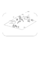
図6は、キャリブレータ8の一例を示す図で、(A)は構造図、(B)はキャリブレータの位置と向きを算出する説明のための平面視の図である。キャリブレータ8は、平板状の基台80の上面に長尺で円柱状の2本のポール81,82が所定の位置関係で立設されており、一体として任意の位置に移動し、設置が可能である。ポール81,82は、レーザを反射するものである。ポール81とポール82とは、2種類の反射体として機能するもので、識別可能なように互いの形状、ここでは半径が大小相違している。なお、キャリブレータ8は、円柱状に限定されず、種々の形状が採用可能であり、また2個に分かれている必要もなく、互いに識別可能な形状部位を有すれば足りる。
先ず、計測装置10のキャリブレーション部123(図4参照)による前段処理が実行される。すなわち、事前準備としての背景点群の取得後に、会場50の適所にセンサ11を設置した状態で、動体検出と同様の方法で計測を行い、背景点群を除いて、例えば図2(B)のような動体点群を得る。
次いで、動体点群から、前記した胴体の検出手法と同様の処理を利用してキャリブレータ8の位置情報の検出を行う。先ず、ポール81,82の直径情報を利用して、動体点群からD1円形(181)の点群と、D2円形(182)の点群とを検出する。さらに、D1円形に相当すると想定される点群集合と、D2円形に相当すると想定される点群集合の各組について、それらの中心間距離Lがキャリブレータ8のポール81-82の中心間距離に近い場合、それらをD1円形、D2円形とみなす。さらに、D1,D2円形の位置情報を用いて、D1,D2円形の中間の位置Pcとセンサ11との間の距離と、センサ11からD2円形の中心を結んだ方向の角度(ベクトル)Diとを算出する。そして、キャリブレーション部123は、算出した距離と角度(ベクトル)Diとをサーバ20に送信する。
ここで、図7を用いて、会場50での2台のセンサ11によるキャリブレーション処理を説明する。図7は、2個のセンサ11,11’が配置される場合の共通のキャリブレータ8を用いたキャリブレーション処理の手順を説明する図で、(A)は1個目のセンサ11とキャリブレータ8との位置関係を示す図、(B)は2個目のセンサ11’とキャリブレータ8との位置関係を示す図である。
図7(C)は、サーバ20のキャリブレーション部212によって実行される処理で、(A)と(B)の結果を合成して、2個のセンサ11,11’の位置をキャリブレートする。
キャリブレーション部212は、センサ11の相対位置の算出及び絶対位置の算出を行う。まず、キャリブレーション部212は、ある時刻に各センサ11で検出されたキャリブレータ8の位置情報を取得し、次いで、キャリブレータ8の位置を起点にして、キャリブレータ8との距離、角度情報を用い、複数のセンサ11の相対位置を特定する(図7(C)参照)。
次に、校正作業者によって、図略の入力操作部を介して、いずれか1つのセンサ11の絶対座標の位置情報が入力設定される。なお、絶対座標系は、世界座標であってもよいし、探知領域全体を共通してカバーするローカル座標であってもよい。キャリブレーション部212は、絶対座標が設定されたセンサ11の絶対位置情報と、その他のセンサ11’の相対位置関係とから、残りの、すなわちセンサ11’の絶対位置情報の算出を行う。
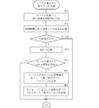
図8は、計測装置10のプロセッサによって実行されるセンサ処理の手順の一例を示すフローチャートである。図8では、先ず事前処理として、静止体からの背景点群の取得処理が実行される(ステップS1)。次いで、計測装置10が起動されて、レーザビームbを周方向に走査させながら周期的な計測処理の動作が開始される(ステップS3)。計測処理においても、歩行者と共に静止体も検出されている。そこで、計測処理において得られた点群データから背景点群を除く処理が行われて、動体点群が検出される(ステップS5)。
次いで、動体点群からグループ化処理を実行して、グループ毎の楕円形の抽出が行われ(ステップS7)、さらに、人の楕円サイズかどうかのフィルタリング処理が実行される(ステップS9)。なお、人の楕円サイズでないと判断された場合、当該グループは検出対象外とされる。続いて、人の胴体の検出処理、すなわち人の胴体の重心座標を時刻 [t-Δt, t] 毎に算出して人座標点を検出する処理が実行される(ステップS11)。さらに、前回(t-Δt)のフレーム、今回tのフレームで検出された人座標点の位置関係から前後フレーム間での同一人物の推定を行って、人物IDの割り当てが行われる(ステップS13)。同一人物である場合、移動軌跡の導出、すなわち各フレーム間の人座標点を時系列につなぎ合わせる処理が行われ(ステップS15)、導出結果は人物IDと共にサーバ20に送信される(ステップS17)。次いで、計測が継続かどうか判断され(ステップS19)、継続であれば、ステップS3に戻って同様な処理が繰り返され、そうでなければ、本フローを終了する。
図9は、サーバのプロセッサによって実行されるマージ処理の手順の一例を示すフローチャートで、(A)はマージ処理Iの手順を示し、(B)はマージ処理IIの手順を示す。マージ処理Iは、計測装置10や、後述するようにモバイル端末30からの送信データの受信を行う処理である。まず、各計測装置10からの送信データの受信が行われ(ステップ#1)、次いで、モバイル端末30からの送信データの受信が行われる(ステップ#3)。
次に、マージ処理IIでは、まず、ある時刻範囲内において各センサ11で検出された各人物の移動軌跡データが抽出され(ステップ#11)、抽出された各人物の移動軌跡データが絶対座標に変換される(ステップ#13)。
次いで、各移動軌跡のペアの組み合わせから各ペアが順次抽出されて、抽出されたペア間での検知時刻毎の位置の差分に基づいたマッチング度の算出が行われる(ステップ#15)。そして、抽出されたペアについて、算出されたマッチング度が閾値以上か否かが判断され(ステップ#17)、閾値以上であれば、当該ペアの移動軌跡は同一人物の移動軌跡であったと見なして統合される(ステップ#19)。一方、マッチングしなかった場合には、ステップ#19をスルーして、別の人物の移動軌跡として扱われる。次いで、次のペアの有無が判断され(ステップ#21)、次のペアが残っていれば、ステップ#15に戻って、残っている内からペアが抽出されて、同様なマッチング処理が実行される。ステップ#21で最後のペアが終了したら、本フローを終了する。
図10は、計測装置10のプロセッサによって実行されるキャリブレーション処理の手順の一例を示すフローチャートである。まず、事前処理として背景点群の取得処理が実行される(ステップS31)。次いで、キャリブレータ8を探知領域、例えば会場50の適所に配置し(図7(A)参照)、その状態で、計測装置10が起動されて、レーザビームbを周方向に走査させながら周期的な計測処理が開始される(ステップS33)。計測処理においても、キャリブレータ8と共に静止体も検出されている。そこで、計測処理において得られた点群データから背景点群を除く処理が行われてキャリブレータ8のポール81,82に対する動体点群が抽出される(ステップS35)。
次いで、動体点群からキャリブレータ8のポール81,82に対応するD1,D2円形の中心の位置情報の算出が行われる(ステップS37)。例えば、ポール81,82に対する位置情報の算出は、図6(B)に示すようにして行われる。このようにして、D1,D2円形の位置情報を用いて、D1,D2円形の中心間距離Lと、ポール81,82の中心間距離との差が算出され、その差が閾値以下であれば、算出した位置情報はキャリブレータ8のポール181,182に対応するものとみなすようにしている(ステップS39)。
次いで、D1,D2円形の中間の位置Pcとセンサ11との間の距離と、センサ11からD2円形の中心を結んだ方向の角度(ベクトル)Diとが算出され(ステップS41)、算出結果はサーバ20に送信される(ステップS43)。
図11は、サーバ20のプロセッサによって実行される各センサ11の絶対位置情報を算出する処理の手順の一例を示すフローチャートである。まず、各計測装置10から算出結果(ステップS41)が受信される(ステップ#31)。
次いで、ある時刻において各計測装置10で検出された前記算出結果を読み出し、これらの算出結果から2つの(または複数の)キャリブレータ8,…が位置、角度において正確に重ね合わされた状態での各センサ11の相対位置関係の算出が行われる(ステップ#33)。次いで、ある1つのセンサ11の、絶対座標系での絶対位置情報がマニュアルでサーバ20(または、当該センサ11を備えた計測装置10を経由しての入力設定でもよい。)に設定される(ステップ#35)。
次いで、キャリブレーション部212は、絶対位置情報が設定されたセンサ11の絶対位置情報とその他のセンサ11の相対位置関係から、残りのセンサ11の絶対位置情報の算出(換算処理)を行う(ステップ#37)。算出された各センサ11の絶対位置情報はデータベース22に格納され、必要に応じて各計測装置10に送信される(ステップ#39)。この結果、各センサ11の位置が共通の座標情報で定義されるため、処理が容易となる。なお、各センサ11の絶対位置情報には、向き情報を含めてもよい。
図12は、検知領域である会場50内での人の移動に伴って、ある領域の通過、例えば出入りを検知する方法を説明する平面視の図である。図12において、会場50には、図の左上と右下とにセンサ11が設置され、図の上の壁51の中央付近に出入り口52が設けられている。図12では、人の移動軌跡として、Tr1,Tr2が検出されている状態を例示している。移動監視部217は、統合後の人の移動軌跡について、ある領域の通過、例えば出入り口を横切ったかどうかを検知し、さらに人数の管理を行う。
軌跡Tr1は、会場50の中央付近で左から右(t4,t3,t2,t1)への移動様態を示している。軌跡Tr2は、会場50内から出入り口52の領域を通過する様子(t4,t3,t2)を検知している。時刻t1の時点では探知領域外に移動しているため、時刻t2後は検知できていない。この例では、軌跡Tr2の歩行者は、(t4,t3,t2)で検知でき、かつ時刻t2と時刻t1との間で出入り口52を通過した(横切った)状態にあるので、退場であることが判り、人数的にマイナス1とすればよい。一方、軌跡Tr2を逆向きに時間が経過したものと仮定すると、外から出入り口52を通過して(横切って)入場したことが検知でき、人数的にプラス1とすればよい。なお、初期の会場人数が既知であれば、かかる人数カウントによって会場内人数をモニタすることが可能となる。センサ11は、出入り口52を簡易的に直線状に形成した出入り領域(通過領域)として検知することで、会場50内の特定の領域を交差する(横切った)ように移動する歩行者をモニタリングできる。
図13は、サーバ20のプロセッサによって実行される人数カウント処理の手順の一例を示すフローチャートである。まず、初期人数iが入力される(ステップ#51)。初期人数が0人の場合には特に入力は不要である。次いで、計測が行われ、移動軌跡が生成されて監視処理が行われる(ステップ#53)。監視処理において、移動軌跡が出入り口52を横切ったかどうかが判断さる(ステップ#55)。出入り口52を「中から外へ」横切った場合(ステップ#57でYes)、人数がi=i-1として減算され(ステップ#59)、逆に、出入り口52を「中から外へ」横切ったのでない場合(すなわち「外から中に」横切った場合)、人数がi=i+1として加算され(ステップ#61)、次いで、ステップ#53に戻って同様な処理が繰り返される。
図14は、人の属性を含めて検知可能にするセンサ11の配置の一実施形態を示す図である。この例では、会場50の床面に設置され、探知面を水平方向とする1台乃至は複数台のセンサ11の他、例えば壁51の、より高い位置に別のセンサ11’が取り付けられている。センサ11’は、探知面が下方に傾斜し、3次元での検知を可能にしている。なお、センサ11’は、より長尺の支柱を有する形状とし、探知面を下方に傾斜させる態様としてもよい。この構成によれば、センサ11によって胴体の検知を介して人の識別及び移動軌跡の検知を可能にする一方、センサ11’によって、移動する人の頭部(最高高さ位置)を検知することで、身長という属性を検知することが可能となり、例えば大人と子供の識別に供することができる。また、センサ11’を用いることで、歩行に従って身体の上下方向の様々な箇所が検知できるため、人体に関する種々の属性(特徴情報)が取得可能となり、適宜の用途に適用できる。
以上のように、計測システム1を適用することで、探知領域において、人々の正確な2次元位置を取得することができる。一方、それらの人々がモバイル端末30を携行していると仮定して、組み合わせ処理部213は、モバイル端末30に内蔵の動きセンサ32を利用して、それらの人の動きを取得し、人の移動軌跡とモバイル端末30とを組み合わせる(紐付けのためのIDを設定する)ようにした。さらに、組み合わせ結果を可視化することで、利用範囲が広がると共に新たな付加価値を得ることも可能となる。
図15は、携行されるモバイル端末30が行うデータ送信処理を示すフローチャートで、(A)はモバイル端末30での組み合わせアプリケーションのインストール処理を示す、サーバへのデータ送信処理Iのフローチャート、(B)は組み合わせ後のモバイル端末30からの受信データの活用処理の一例を示す、サーバへのデータ送信処理IIのフローチャートである。
図15(A)において、まず、会場50への入場に先立って、例えば出入り口52近くに設置された2次元バーコードであるQRコード(登録商標)をモバイル端末30のデジタルカメラで撮像し、モバイル端末内の処理部によってQRコード(登録商標)が解析され、地上局41、インターネット40を経て、該当のURL(Uniform ResourceLocator)のサイトにアクセスして、「ひとなび」アプリケーションをインストールするようになっている(ステップST1)。または、インターネット上の特定のサイトから事前に、あるいは出入り口52に配置されたアクセスポイント201と交信して、「ひとなび」アプリケーションをインストールするようにしてもよい。「ひとなび」アプリケーションがインストールされる際に、自己のモバイル端末30のアドレスがサーバ20に登録され、以後、サーバ20側からのアクセスが可能とされる。
「ひとなび」アプリケーションとは、モバイル端末30に内蔵された動きセンサ32の検出情報を継続的に読み取って、Wi-Fiなどの近距離通信を介してサーバ20に送信する(ステップST3)。
図15(B)において、まず、入力部34からのメッセージの入力の有無が判断される(ステップST11)。メッセージの入力がある場合、「ひとなび」アプリケーションによって、メッセージがサーバ20に送信され(ステップST13)、メッセージの入力がない場合、ステップST13がスキップされる。
さらに、「ひとなび」アプリケーションによって、メッセージの受信の有無が判断される(ステップST15)。メッセージの受信がある場合、俯瞰領域顔図内で、紐付けされたモバイル端末30に吹出し図形で受信メッセージの表示が行われ(ステップST17)、メッセージの受信がない場合、ステップST17がスキップされる。
図16は、サーバ20の組み合わせ処理部213が実行する、携行のモバイル端末30の動きと移動軌跡との組み合わせ処理の一例を示すフローチャートである。モバイル端末30から動き情報が周期的に受信され(ステップ#71)、次いで移動軌跡と動き情報との共通性の評価が行われる(ステップ#73)。共通性評価のための組み合わせ処理とは、動きセンサ32から得られた動きと探知領域内で検知した人の移動軌跡との同一時刻における一致さを評価して、同一人物といえるかどうかを評価するものである。共通性の有無の判断が行われ(ステップ#75)、共通性がなければ、本フローを終了する。一方、共通性があれば、紐付け処理が実行される(ステップ#77)。
次いで、紐付けされているモバイル端末30からSNS情報を受信したかどうかが判断される(ステップ#79)。SNS情報を受信しなければ、本フローを終了する。一方、SNS情報を受信すると、サイネージ画像作成部214によって、モバイル端末30からの受信情報が加工され、人物の画像と対応付けてサイネージの表示器202に表示される(ステップ#81)。次いで、サイネージの表示器202に表示された情報を、紐付けされたモバイル端末30にそれぞれ送信する(ステップ#83)。
図17は、モバイル端末画像作成部215によってモバイル端末30の表示部311に表示される画面例の図である。画面には、会場画像G50が俯瞰して表示されている。さらに、IDで紐付けして、モバイル端末30が内蔵する他のセンサ等から得られる情報(温度、湿度、騒がしさ、気圧、周囲の混雑など)をアクセスポイント201を介して、また、ツイート(Tweet)等、そのモバイル端末30の所持者が興味を持ったりレポートしたりする情報にタイムスタンプを付与した「モバイル端末データ」を地上局41を介して、サーバ20にそれぞれ送信されて画面に反映される。
サイネージ用の表示器202の画面、あるいはモバイル端末30の表示部311の画面には、各人の位置に対応して人マーク、例えばアバター画像(図17の画像G6参照)が表示されると共に、「モバイル端末データ」が吹出し(図17の画像G71参照)を用いて表示される。これにより、各モバイル端末30の正しい位置情報とともに、そのモバイル端末30が捉えた「モバイル端末データ」が、それらの画面に表示される会場画像G50に、一括して表示できる。また、図17に示すように、当人のモバイル端末30の表示部311に対しては、本人を表すマーク(画像G72参照)が付された画像としてもよい。また、表示器202、表示部311には、各人の移動軌跡をある時間幅だけ表示してもよい。
図18は、移動監視部217によって実行される、交通機関に対する乗客の昇降数をカウントする適用例を示す図である。この構成は、図12に示す、会場50に対して出入りする人数をカウントする態様と似ている。すなわち、図18は、バスの乗客数をカウントする態様である。バスは、後部側の昇降口付近を示す車内部BUの側部B51に沿って座席SEATが適宜設置され、昇降口にドアB52が開閉可能に設けられている。ドア開閉センサ9は、図略の駆動源で図示の矢印に示すようにスライドするドアB52の開閉を検出する、例えば機械的なスイッチである。計測部12を内装する形態のセンサ11は、好ましくは複数設置され、1つはドアB52の近傍に配置されていてもよい。
サーバ20’は、図3の構成を備えると共に、図13のフローチャートと同様な処理を実行する。これによって、車内部BUに対して昇降する人数が検知でき、それによって各時点で乗客数が把握可能となる。また、サーバ20’のドア開閉検出部29で検出される各停留所でのドアB52の開閉時刻及び開成時間を昇降人数と関連付けることで、運行状況の把握乃至はその管理に反映させることができる。
なお、本発明において、モバイル端末との組み合わせ方法として以下の方法も採用可能である。すなわち、センサ11によって探知領域、例えば会場50に進入した歩行者は位置が検知され、トラッキングされる。サーバ20は、「ひとなび」アプリがインストールされたことを条件に、かかるモバイル端末30に対して、アクセスポイント201を経て位置情報の問い合わせ要求を発する。進入した歩行者がモバイル端末30を携行していれば、要求に応じて自己の位置情報をサーバ20にアクセスポイント201を経て返信する。進入した歩行者の移動軌跡及び時刻と返信された位置情報及び時刻とを比較し、同じ位置と見なせる場合、当該歩行者のモバイル端末30が進入したと判断する。従って、歩行者は、探知領域内にいる間、センサ11で得られた正確な移動軌跡をサーバ20を介してモバイル端末30で取得できる。なお、モバイル端末30の位置を取得する方法としては、Wi-Fi基地局からの電波強度の違いを利用する方式、ビーコン測位(BLE:BluetoohLow Energy)方式、その他が採用可能である。
また、本実施形態では、キャリブレータ8の構造として、図6に示すように、基台80の上面に立設した2本のポール81,82を採用したが、これに代えて、基台80と1個のポール81を別体として採用する態様としてもよい。この態様では、ポール81を予め立直させる基台80上の位置を複数箇所、例えば2箇所に目印を付して設定しておけばよい。そして、キャリブレーション処理に際して、1箇所目と2箇所目とに順番にポール81を置き換えてそれぞれ計測を行うことで、図10と同様に2箇所の計測処理が実行される。なお、ポール81に代えてポール82でもよく、あるいは他の態様のポールでもよい。
また、本実施形態では、人の移動軌跡を検知したが、検知対象は人以外であってもよい。例えば、工場内を自立的に走行する運搬ロボットの移動軌跡をモニタリングすることで、衝突、異常走行また暴走を検知し、阻止することが可能となる。
以上説明したように、本発明に係る計測装置は、走査範囲内を繰り返し走査しながら周期的にレーザビームを送信すると共に、探知領域内の動体の各部で反射したレーザビームを受信するセンサと、受信した前記レーザビームから前記動体の各部に対応した動体点群の位置を算出し、算出した前記動体点群から楕円の胴体を抽出し、抽出した前記楕円の胴体の重心位置を順次算出する第1の算出手段と、算出した前記胴体の重心位置のうち、2つの胴体の重心位置の間の距離が閾値以下かどうかを判定し、閾値以下とされた胴体に対して共通IDを付す第2の算出手段と、前記共通IDが付された前記胴体の重心位置を時系列につなぎ合わせて移動軌跡を生成する移動軌跡生成手段とを備えたものである。
本発明によれば、走査範囲内を繰り返し走査しながら周期的にセンサからレーザビームが送信され、レーザビームは探知領域内に存在する動体の各部で反射して受信される。そして、第1の算出手段によって、受信した前記レーザビームから前記動体の各部に対応した動体点群の位置が算出され、算出された前記動体点群から楕円の胴体が抽出され、さらに抽出された前記楕円の胴体の重心位置が順次算出される。さらに、第2の算出手段によって、前記胴体の重心位置のうち、2つの胴体の重心位置の間の距離が閾値以下かどうかが判定され、閾値以下と判定される胴体に対して共通IDが付与される。そして、移動軌跡生成手段によって、前記共通IDが付与された前記胴体の重心位置が時系列につなぎ合わされる。従って、計測装置は、自己のセンサから取得された位置情報から移動軌跡情報を算出するようにし、これによってサーバ側のデータ処理負担の低減に供することが可能となる。また、2つの胴体の重心位置の間の距離が閾値以下と判定された場合に、同一の動体とすることで、一時的に静止する(立ち止まる)ような状態でも同一動体として適正に検知される。
また、予め前記探知領域に存在する静止体の位置を背景点群として算出する背景処理手段を備え、前記第1の算出手段は、前記背景点群との差分を取って前記動体点群を導出するものである。この構成によれば、背景にある静止体の影響が排除される。
また、前記第1の算出手段は、前記動体点群の中から、下記条件α、β、γを用いてグループ化を行い、各グループを前記楕円の胴体とするものである。但し、グループ内の最大距離がある定数α以下、かつグループ外の動体点群との最小距離がある定数β以上、かつグループ内の動体点群の数がある定数γ以上である。この構成によれば、一人ずつを的確に検出することが可能となる。
また、前記定数αは、α=R+V*Δtとすることが好ましい。但し、Rは胴体の最大直径として想定した値、Vは平均的な歩行速度、Δtは前記時系列における時間間隔である。この構成によれば、人の一般的な歩行速度を考慮して一人ずつの検出範囲が設定される。
また、前記第2の算出手段は、前記時系列における複数の周期分の前記胴体の重心位置を用いて、途切れた胴体の重心位置を補間するものである。この構成によれば、センサとの間を他の動体が横切るような場合であっても、その間の重心位置を補間することで得られる。
また、本発明に係る計測システムは、検知範囲が一部重なるように配置された前記計測装置と、前記各計測装置で生成された前記各移動軌跡の情報を取得するサーバとを備え、前記サーバは、前記計測装置間における移動軌跡のペアを抽出し、各ペアに対して移動軌跡のマッチング処理を行う移動軌跡統合手段を備えたものである。
本発明によれば、サーバの移動軌跡統合手段によって、前記計測装置間における移動軌跡のペアを抽出し、各ペアに対して移動軌跡のマッチング処理を行うだけとしたので、サーバでのデータ処理負担が低減する。
また、本発明に係る計測システムは、反射体を備えたキャリブレータを備え、前記計測装置は、前記キャリブレータの少なくとも第1の位置と第2の位置とに立直された前記反射体を前記センサによって検出することによって、前記キャリブレータの位置及び向きの情報を取得する装置側キャリブレーション手段を備え、前記サーバは、複数の計測装置で取得した前記キャリブレータの位置及び向きを共通座標系で重ね合わせて、各センサの設置位置を算出するサーバ側キャリブレーション手段を備えたものである。この構成によれば、複数のセンサ間の配置位置が校正されるため、各センサの配置位置情報の精度が維持される。
また、前記サーバは、モバイル端末の動きセンサからの動き情報と、前記動体の移動軌跡との共通性を評価し、共通性がある場合、前記動体の移動軌跡と前記モバイル端末とを組み合わせる組み合わせ処理手段を備えるものである。この構成によれば、センサで検出された人の移動軌跡と、当該人が携行するモバイル端末とが組み合わされるため、移動軌跡にモバイル端末からの情報を関連付けることが可能となり、また情報の有効活用が図れる。
また、前記サーバは、前記動体の移動軌跡が前記探知領域内の特定の領域を通過したかどうかを検知する移動監視手段を備えたことを特徴とするものである。この構成によれば、探知領域内に特定の領域を検知可能に定義づけておけば、当該特定領域の動体の通過状況の監視が可能となる。
また、前記移動監視手段は、バスの昇降領域を横切って乗車及び降車する乗客の人数を監視するものである。この構成によれば、前記特定の領域としてバスの昇降領域が設定された場合、バスの乗降人数ひいては乗車人数の監視が可能となる。
1 計測システム
8 キャリブレータ
10 計測装置
11,11’ センサ
120 制御部
123 キャリブレーション部(装置側キャリブレーション手段)
124 背景処理部(背景処理手段)
125 人検出部(第1の算出手段、第2の算出手段)
126 移動軌跡生成部(移動軌跡生成手段)
20 サーバ
21 処理部
211 移動軌跡統合部(移動軌跡統合手段)
212 キャリブレーション部(サーバ側キャリブレーション手段)
213 組み合わせ処理部(組み合わせ処理手段)
217 移動監視部(移動監視手段)
30 モバイル端末
52 出入り口
BU 車内部
8 キャリブレータ
10 計測装置
11,11’ センサ
120 制御部
123 キャリブレーション部(装置側キャリブレーション手段)
124 背景処理部(背景処理手段)
125 人検出部(第1の算出手段、第2の算出手段)
126 移動軌跡生成部(移動軌跡生成手段)
20 サーバ
21 処理部
211 移動軌跡統合部(移動軌跡統合手段)
212 キャリブレーション部(サーバ側キャリブレーション手段)
213 組み合わせ処理部(組み合わせ処理手段)
217 移動監視部(移動監視手段)
30 モバイル端末
52 出入り口
BU 車内部
Claims (10)
- 走査範囲内を繰り返し走査しながら周期的にレーザビームを送信すると共に、探知領域内の動体の各部で反射したレーザビームを受信するセンサと、
受信した前記レーザビームから前記動体の各部に対応した動体点群の位置を算出し、算出した前記動体点群から楕円の胴体を抽出し、抽出した前記楕円の胴体の重心位置を順次算出する第1の算出手段と、
算出した前記胴体の重心位置のうち、2つの胴体の重心位置の間の距離が閾値以下かどうかを判定し、閾値以下とされた胴体に対して共通IDを付す第2の算出手段と、
前記共通IDが付された前記胴体の重心位置を時系列につなぎ合わせて移動軌跡を生成する移動軌跡生成手段とを備えた計測装置。 - 予め前記探知領域に存在する静止体の位置を背景点群として算出する背景処理手段を備え、
前記第1の算出手段は、前記背景点群との差分を取って前記動体点群を導出する請求項1に記載の計測装置。 - 前記第1の算出手段は、前記動体点群の中から、下記条件α、β、γを用いてグループ化を行い、各グループを前記楕円の胴体とする請求項1に記載の計測装置。
但し、グループ内の最大距離がある定数α以下、かつグループ外の動体点群との最小距離がある定数β以上、かつグループ内の動体点群の数がある定数γ以上であること。 - 前記定数αは、α=R+V*Δtである請求項1に記載の計測装置。
但し、Rは胴体の最大直径として想定した値、Vは平均的な歩行速度、Δtは前記時系列における時間間隔である。 - 前記第2の算出手段は、前記時系列における複数の周期分の前記胴体の重心位置を用いて、途切れた胴体の重心位置を補間する請求項1に記載の計測装置。
- 検知範囲が一部重なるように配置された、請求項1~5のいずれかに記載の計測装置と、前記各計測装置で生成された前記各移動軌跡の情報を取得するサーバとを備え、
前記サーバは、前記計測装置間における移動軌跡のペアを抽出し、各ペアに対して移動軌跡のマッチング処理を行う移動軌跡統合手段を備えた計測システム。 - 反射体を備えたキャリブレータを備え、
前記計測装置は、前記キャリブレータの少なくとも第1の位置と第2の位置とに立直された前記反射体を前記センサによって検出することによって、前記キャリブレータの位置及び向きの情報を取得する装置側キャリブレーション手段を備え、
前記サーバは、複数の計測装置で取得した前記キャリブレータの位置及び向きを共通座標系で重ね合わせて、各センサの設置位置を算出するサーバ側キャリブレーション手段を備えた請求項6に記載の計測システム。 - 前記サーバは、モバイル端末の動きセンサからの動き情報と、前記動体の移動軌跡との共通性を評価し、共通性がある場合、前記動体の移動軌跡と前記モバイル端末とを組み合わせる組み合わせ処理手段を備える請求項6又は7に記載の計測システム。
- 前記サーバは、前記動体の移動軌跡が前記探知領域内の特定の領域を通過したかどうかを検知する移動監視手段を備えたことを特徴とする請求項6~8のいずれかに記載の計測システム。
- 前記移動監視手段は、バスの昇降領域を横切って乗車及び降車する乗客の人数を監視する請求項9に記載の計測システム。
Priority Applications (1)
| Application Number | Priority Date | Filing Date | Title |
|---|---|---|---|
| JP2020553184A JP7339485B2 (ja) | 2018-10-22 | 2019-10-15 | 計測システム |
Applications Claiming Priority (2)
| Application Number | Priority Date | Filing Date | Title |
|---|---|---|---|
| JP2018-198098 | 2018-10-22 | ||
| JP2018198098 | 2018-10-22 |
Publications (1)
| Publication Number | Publication Date |
|---|---|
| WO2020085142A1 true WO2020085142A1 (ja) | 2020-04-30 |
Family
ID=70330466
Family Applications (1)
| Application Number | Title | Priority Date | Filing Date |
|---|---|---|---|
| PCT/JP2019/040429 Ceased WO2020085142A1 (ja) | 2018-10-22 | 2019-10-15 | 計測装置及び計測システム |
Country Status (3)
| Country | Link |
|---|---|
| JP (1) | JP7339485B2 (ja) |
| TW (1) | TW202104929A (ja) |
| WO (1) | WO2020085142A1 (ja) |
Cited By (3)
| Publication number | Priority date | Publication date | Assignee | Title |
|---|---|---|---|---|
| CN113671513A (zh) * | 2020-05-14 | 2021-11-19 | 日立乐金光科技株式会社 | 测距系统以及测距传感器的校准方法 |
| JP2022026109A (ja) * | 2020-07-30 | 2022-02-10 | パナソニックIpマネジメント株式会社 | 在席検知システムおよび在席検知方法 |
| US12423946B2 (en) | 2021-09-22 | 2025-09-23 | Toyota Jidosha Kabushiki Kaisha | Method, apparatus, and program for matching point cloud data |
Families Citing this family (2)
| Publication number | Priority date | Publication date | Assignee | Title |
|---|---|---|---|---|
| TWI807340B (zh) * | 2021-06-16 | 2023-07-01 | 信邦電子股份有限公司 | 車輛自動定位管理系統及方法 |
| US11756423B2 (en) | 2021-07-07 | 2023-09-12 | Sinbon Electronics Company Ltd. | Automatic vehicle positioning management system and method thereof |
Citations (5)
| Publication number | Priority date | Publication date | Assignee | Title |
|---|---|---|---|---|
| JP2001227942A (ja) * | 2000-02-14 | 2001-08-24 | Mazda Motor Corp | 車両の物体認識装置 |
| JP2011081634A (ja) * | 2009-10-07 | 2011-04-21 | Sogo Keibi Hosho Co Ltd | 人体向き推定装置及び人体向き推定方法 |
| WO2014045521A1 (ja) * | 2012-09-19 | 2014-03-27 | 日本電気株式会社 | 配置スコア算出システム、方法およびプログラム |
| JP2018119833A (ja) * | 2017-01-24 | 2018-08-02 | キヤノン株式会社 | 情報処理装置、システム、推定方法、コンピュータプログラム、及び記憶媒体 |
| JP2018159693A (ja) * | 2017-03-24 | 2018-10-11 | 富士通株式会社 | 情報処理プログラム、情報処理方法、および情報処理装置 |
-
2019
- 2019-10-15 WO PCT/JP2019/040429 patent/WO2020085142A1/ja not_active Ceased
- 2019-10-15 JP JP2020553184A patent/JP7339485B2/ja active Active
- 2019-10-21 TW TW108137898A patent/TW202104929A/zh unknown
Patent Citations (5)
| Publication number | Priority date | Publication date | Assignee | Title |
|---|---|---|---|---|
| JP2001227942A (ja) * | 2000-02-14 | 2001-08-24 | Mazda Motor Corp | 車両の物体認識装置 |
| JP2011081634A (ja) * | 2009-10-07 | 2011-04-21 | Sogo Keibi Hosho Co Ltd | 人体向き推定装置及び人体向き推定方法 |
| WO2014045521A1 (ja) * | 2012-09-19 | 2014-03-27 | 日本電気株式会社 | 配置スコア算出システム、方法およびプログラム |
| JP2018119833A (ja) * | 2017-01-24 | 2018-08-02 | キヤノン株式会社 | 情報処理装置、システム、推定方法、コンピュータプログラム、及び記憶媒体 |
| JP2018159693A (ja) * | 2017-03-24 | 2018-10-11 | 富士通株式会社 | 情報処理プログラム、情報処理方法、および情報処理装置 |
Cited By (5)
| Publication number | Priority date | Publication date | Assignee | Title |
|---|---|---|---|---|
| CN113671513A (zh) * | 2020-05-14 | 2021-11-19 | 日立乐金光科技株式会社 | 测距系统以及测距传感器的校准方法 |
| CN113671513B (zh) * | 2020-05-14 | 2024-02-23 | 日立乐金光科技株式会社 | 测距系统以及测距传感器的校准方法 |
| JP2022026109A (ja) * | 2020-07-30 | 2022-02-10 | パナソニックIpマネジメント株式会社 | 在席検知システムおよび在席検知方法 |
| JP7499449B2 (ja) | 2020-07-30 | 2024-06-14 | パナソニックIpマネジメント株式会社 | 在席検知システムおよび在席検知方法 |
| US12423946B2 (en) | 2021-09-22 | 2025-09-23 | Toyota Jidosha Kabushiki Kaisha | Method, apparatus, and program for matching point cloud data |
Also Published As
| Publication number | Publication date |
|---|---|
| TW202104929A (zh) | 2021-02-01 |
| JP7339485B2 (ja) | 2023-09-06 |
| JPWO2020085142A1 (ja) | 2021-10-21 |
Similar Documents
| Publication | Publication Date | Title |
|---|---|---|
| JP7339485B2 (ja) | 計測システム | |
| KR102399591B1 (ko) | 관심 지역 및 입구의 위치를 결정하는 시스템 | |
| US11785430B2 (en) | System and method for real-time indoor navigation | |
| US11960028B2 (en) | Determining specular reflectivity characteristics using LiDAR | |
| US10798527B2 (en) | Cognitive progressive method and system for deploying indoor location sensor networks | |
| EP3213031B1 (en) | Simultaneous localization and mapping by using earth's magnetic fields | |
| US9641814B2 (en) | Crowd sourced vision and sensor-surveyed mapping | |
| US20190086545A1 (en) | Lidar sensing system | |
| CN106405605B (zh) | 一种机器人基于ros和gps的室内外无缝定位方法和定位系统 | |
| US20140297090A1 (en) | Autonomous Mobile Method and Autonomous Mobile Device | |
| JP2014524577A (ja) | 屋内測位のためのロゴ検出 | |
| CN111272172A (zh) | 无人机室内导航方法、装置、设备和存储介质 | |
| US20220377285A1 (en) | Enhanced video system | |
| EP3234505B1 (en) | Providing constraint to a position | |
| JP2019175128A (ja) | 移動制御システム | |
| Shin et al. | Vehicle tracking system in underground parking lots using smartphone | |
| US11720117B1 (en) | System to facilitate autonomous mobile device movement | |
| Sternberg et al. | Precise indoor mapping as a basis for coarse indoor navigation. | |
| Palaniappan et al. | Autonomous RF surveying robot for indoor localization and tracking | |
| Yeh et al. | Performance improvement of offline phase for indoor positioning systems using Asus Xtion and smartphone sensors | |
| JP2023104601A (ja) | 移動体用の経路計画装置及び方法、移動体、並びに、移動体制御システム | |
| Kim et al. | Design and implementation of mobile indoor scanning system | |
| JP2023104604A (ja) | 移動体用の経路計画装置及び方法、移動体、並びに、移動体制御システム | |
| EP3460522A1 (en) | Light detection and ranging sensing system | |
| Nagaraju et al. | Crowd-sourced ai based indoor localization using support vector regression and pedestrian dead reckoning |
Legal Events
| Date | Code | Title | Description |
|---|---|---|---|
| 121 | Ep: the epo has been informed by wipo that ep was designated in this application |
Ref document number: 19875333 Country of ref document: EP Kind code of ref document: A1 |
|
| ENP | Entry into the national phase |
Ref document number: 2020553184 Country of ref document: JP Kind code of ref document: A |
|
| NENP | Non-entry into the national phase |
Ref country code: DE |
|
| 122 | Ep: pct application non-entry in european phase |
Ref document number: 19875333 Country of ref document: EP Kind code of ref document: A1 |