WO2020084716A1 - Additive manufacturing device and numerical value control device - Google Patents
Additive manufacturing device and numerical value control device Download PDFInfo
- Publication number
- WO2020084716A1 WO2020084716A1 PCT/JP2018/039544 JP2018039544W WO2020084716A1 WO 2020084716 A1 WO2020084716 A1 WO 2020084716A1 JP 2018039544 W JP2018039544 W JP 2018039544W WO 2020084716 A1 WO2020084716 A1 WO 2020084716A1
- Authority
- WO
- WIPO (PCT)
- Prior art keywords
- wire
- drive
- manufacturing apparatus
- additional manufacturing
- time point
- Prior art date
Links
Images


Classifications
-
- B—PERFORMING OPERATIONS; TRANSPORTING
- B23—MACHINE TOOLS; METAL-WORKING NOT OTHERWISE PROVIDED FOR
- B23K—SOLDERING OR UNSOLDERING; WELDING; CLADDING OR PLATING BY SOLDERING OR WELDING; CUTTING BY APPLYING HEAT LOCALLY, e.g. FLAME CUTTING; WORKING BY LASER BEAM
- B23K26/00—Working by laser beam, e.g. welding, cutting or boring
- B23K26/34—Laser welding for purposes other than joining
- B23K26/342—Build-up welding
-
- B—PERFORMING OPERATIONS; TRANSPORTING
- B23—MACHINE TOOLS; METAL-WORKING NOT OTHERWISE PROVIDED FOR
- B23K—SOLDERING OR UNSOLDERING; WELDING; CLADDING OR PLATING BY SOLDERING OR WELDING; CUTTING BY APPLYING HEAT LOCALLY, e.g. FLAME CUTTING; WORKING BY LASER BEAM
- B23K26/00—Working by laser beam, e.g. welding, cutting or boring
- B23K26/34—Laser welding for purposes other than joining
-
- B—PERFORMING OPERATIONS; TRANSPORTING
- B22—CASTING; POWDER METALLURGY
- B22F—WORKING METALLIC POWDER; MANUFACTURE OF ARTICLES FROM METALLIC POWDER; MAKING METALLIC POWDER; APPARATUS OR DEVICES SPECIALLY ADAPTED FOR METALLIC POWDER
- B22F10/00—Additive manufacturing of workpieces or articles from metallic powder
- B22F10/50—Treatment of workpieces or articles during build-up, e.g. treatments applied to fused layers during build-up
-
- B—PERFORMING OPERATIONS; TRANSPORTING
- B22—CASTING; POWDER METALLURGY
- B22F—WORKING METALLIC POWDER; MANUFACTURE OF ARTICLES FROM METALLIC POWDER; MAKING METALLIC POWDER; APPARATUS OR DEVICES SPECIALLY ADAPTED FOR METALLIC POWDER
- B22F10/00—Additive manufacturing of workpieces or articles from metallic powder
- B22F10/80—Data acquisition or data processing
- B22F10/85—Data acquisition or data processing for controlling or regulating additive manufacturing processes
-
- B—PERFORMING OPERATIONS; TRANSPORTING
- B22—CASTING; POWDER METALLURGY
- B22F—WORKING METALLIC POWDER; MANUFACTURE OF ARTICLES FROM METALLIC POWDER; MAKING METALLIC POWDER; APPARATUS OR DEVICES SPECIALLY ADAPTED FOR METALLIC POWDER
- B22F12/00—Apparatus or devices specially adapted for additive manufacturing; Auxiliary means for additive manufacturing; Combinations of additive manufacturing apparatus or devices with other processing apparatus or devices
- B22F12/30—Platforms or substrates
- B22F12/33—Platforms or substrates translatory in the deposition plane
-
- B—PERFORMING OPERATIONS; TRANSPORTING
- B23—MACHINE TOOLS; METAL-WORKING NOT OTHERWISE PROVIDED FOR
- B23K—SOLDERING OR UNSOLDERING; WELDING; CLADDING OR PLATING BY SOLDERING OR WELDING; CUTTING BY APPLYING HEAT LOCALLY, e.g. FLAME CUTTING; WORKING BY LASER BEAM
- B23K15/00—Electron-beam welding or cutting
- B23K15/0046—Welding
- B23K15/0086—Welding welding for purposes other than joining, e.g. built-up welding
-
- B—PERFORMING OPERATIONS; TRANSPORTING
- B33—ADDITIVE MANUFACTURING TECHNOLOGY
- B33Y—ADDITIVE MANUFACTURING, i.e. MANUFACTURING OF THREE-DIMENSIONAL [3-D] OBJECTS BY ADDITIVE DEPOSITION, ADDITIVE AGGLOMERATION OR ADDITIVE LAYERING, e.g. BY 3-D PRINTING, STEREOLITHOGRAPHY OR SELECTIVE LASER SINTERING
- B33Y30/00—Apparatus for additive manufacturing; Details thereof or accessories therefor
-
- B—PERFORMING OPERATIONS; TRANSPORTING
- B33—ADDITIVE MANUFACTURING TECHNOLOGY
- B33Y—ADDITIVE MANUFACTURING, i.e. MANUFACTURING OF THREE-DIMENSIONAL [3-D] OBJECTS BY ADDITIVE DEPOSITION, ADDITIVE AGGLOMERATION OR ADDITIVE LAYERING, e.g. BY 3-D PRINTING, STEREOLITHOGRAPHY OR SELECTIVE LASER SINTERING
- B33Y40/00—Auxiliary operations or equipment, e.g. for material handling
-
- B—PERFORMING OPERATIONS; TRANSPORTING
- B33—ADDITIVE MANUFACTURING TECHNOLOGY
- B33Y—ADDITIVE MANUFACTURING, i.e. MANUFACTURING OF THREE-DIMENSIONAL [3-D] OBJECTS BY ADDITIVE DEPOSITION, ADDITIVE AGGLOMERATION OR ADDITIVE LAYERING, e.g. BY 3-D PRINTING, STEREOLITHOGRAPHY OR SELECTIVE LASER SINTERING
- B33Y50/00—Data acquisition or data processing for additive manufacturing
- B33Y50/02—Data acquisition or data processing for additive manufacturing for controlling or regulating additive manufacturing processes
-
- Y—GENERAL TAGGING OF NEW TECHNOLOGICAL DEVELOPMENTS; GENERAL TAGGING OF CROSS-SECTIONAL TECHNOLOGIES SPANNING OVER SEVERAL SECTIONS OF THE IPC; TECHNICAL SUBJECTS COVERED BY FORMER USPC CROSS-REFERENCE ART COLLECTIONS [XRACs] AND DIGESTS
- Y02—TECHNOLOGIES OR APPLICATIONS FOR MITIGATION OR ADAPTATION AGAINST CLIMATE CHANGE
- Y02P—CLIMATE CHANGE MITIGATION TECHNOLOGIES IN THE PRODUCTION OR PROCESSING OF GOODS
- Y02P10/00—Technologies related to metal processing
- Y02P10/25—Process efficiency
Definitions
- the present invention relates to an additional manufacturing apparatus that adds a material to a workpiece to manufacture a modeled object and a numerical control apparatus that controls the additional manufacturing apparatus.
- An additional manufacturing device that manufactures a three-dimensional shaped object by the Direct Energy Deposition (DED) method.
- Some additional manufacturing apparatuses manufacture a modeled object by locally melting a material with a beam emitted from a processing head and adding the melted material to a workpiece.
- DED Direct Energy Deposition
- An additional manufacturing apparatus that uses a wire of a metal material as a material moves the irradiation position while supplying the wire to the irradiation position of the beam to form a linear bead, which is a solidified material of the molten metal material.
- the additional manufacturing apparatus retracts the wire from the workpiece while the material is molten before the wire is fixed to the bead at the end portion where the bead formation is stopped.
- Patent Document 1 discloses a method of welding a metal material by irradiating the metal material with a laser beam while supplying the wire with the laser beam, while gradually delaying the supply of the wire at the terminal end of the welded portion. It is disclosed that the irradiation of the laser beam is stopped after the laser beam is separated from the welded portion.
- the additive manufacturing apparatus can reduce the sticking of the wire to the bead, but on the other hand, there is a problem in that the processing quality is deteriorated due to the formation of a lump at the tip of the wire.
- the present invention has been made in view of the above, and an object of the present invention is to obtain an additional manufacturing apparatus capable of improving processing quality.
- the additive manufacturing apparatus adds a material melted by irradiation of a beam to a workpiece to manufacture a modeled object.
- An additional manufacturing apparatus includes a beam source that outputs a beam, and a drive unit that changes a relative position between a material sent from a material supply source and a workpiece.
- the drive unit is capable of performing a first drive for feeding the material from the supply source toward the workpiece and a second drive for pulling the fed material back to the supply source, Based on this, switching from the first drive to the second drive is performed.
- the additional manufacturing apparatus according to the present invention has the effect of improving the processing quality.
- FIG. 6 is a diagram illustrating a comparative example of Embodiment 1.
- FIG. 6 is a diagram for explaining the operation of the additional manufacturing apparatus according to the first embodiment.
- the figure explaining the mode of a laser beam and a wire in the additional manufacturing apparatus shown in FIG. 3 is a flowchart showing a procedure of operations performed by the additional manufacturing apparatus according to the first embodiment.
- FIG. 8 is a diagram for explaining the operation of the additional manufacturing apparatus according to the second embodiment.
- NC Numerical Control
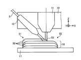
- FIG. 1 is a diagram showing an additional manufacturing apparatus 100 according to the first embodiment of the present invention.
- the additive manufacturing apparatus 100 is a machine tool that manufactures a modeled object by an additive process of adding a material melted by beam irradiation to a workpiece.
- the beam is a laser beam and the material is the wire 5 made of a metallic material.
- the additive manufacturing apparatus 100 forms beads 18 on the base material 17 to form a deposit 18 made of a metal material on the surface of the base material 17.
- the bead is a linear object formed by solidifying the molten wire 5.
- the base material 17 is placed on the stage 15.
- the work piece refers to the base material 17 and the deposit 18.
- the modeled object refers to the base material 17 and the deposit 18 after the addition of the material according to the processing program is completed.
- the base material 17 shown in FIG. 1 is a plate material.
- the base material 17 may be something other than a plate material.
- the additional manufacturing apparatus 100 includes a processing head 10 having a beam nozzle 11, a wire nozzle 12, and a gas nozzle.
- the beam nozzle 11 emits a laser beam that melts a material toward a workpiece.
- the wire nozzle 12 advances the wire 5 toward the irradiation position of the laser beam on the workpiece.
- the gas nozzle ejects a gas for suppressing the oxidation of the deposit 18 and cooling the bead toward the workpiece. In FIG. 1, the illustration of the gas nozzle is omitted.
- the processing head 10 is provided with a temperature sensor 9 and a camera 19.
- the laser oscillator 2 which is a beam source, oscillates a laser beam.
- the laser beam from the laser oscillator 2 propagates to the beam nozzle 11 through the fiber cable 3 which is an optical transmission line.
- the gas supply device 7 supplies gas to the gas nozzle through the pipe 8.
- the gas nozzle ejects gas along the central axis of the laser beam emitted from the beam nozzle 11. That is, the beam nozzle 11 and the gas nozzle are coaxially arranged.
- the gas nozzle may be provided at a position other than the position coaxial with the beam nozzle 11.
- the wire spool 6 around which the wire 5 is wound is a material supply source.
- the rotary motor 4 is a supply drive unit for supplying the material.
- the wire spool 6 rotates as the rotary motor 4, which is a servo motor, is driven to rotate.
- the rotary motor 4 performs a first drive for feeding the wire 5 from the wire spool 6 toward the workpiece, and a second drive for pulling the fed wire 5 back to the wire spool 6.
- the rotary motor 4 rotates the wire spool 6 in the first direction by the first drive, and rotates the wire spool 6 in the second direction opposite to the first direction by the second drive.
- the first direction is the counterclockwise direction and the second direction is the clockwise direction.
- the rotary motor 4 switches from the first drive to the second drive based on the machining program.
- the rotary motor 4 changes the relative position between the tip of the wire 5 sent from the wire spool 6 and the workpiece by switching from the first drive to the second drive.
- the wire 5 sent from the wire spool 6 is passed through the wire nozzle 12 and supplied to the laser beam irradiation position.
- the wire nozzle 12 may be provided with an operation mechanism for pulling out the wire 5 from the wire spool 6.
- the additional manufacturing apparatus 100 is provided with at least one of the rotation motor 4 connected to the wire spool 6 and the operation mechanism of the wire nozzle 12, so that the wire 5 can be supplied to the irradiation position of the laser beam.
- Such an operating mechanism is a feeding drive for feeding the material.
- FIG. 1 the illustration of the operation mechanism of the wire nozzle 12 is omitted.
- the head drive unit 14 moves the processing head 10 in each of the X-axis direction, the Y-axis direction, and the Z-axis direction.
- the X axis, the Y axis, and the Z axis are three axes that are perpendicular to each other.
- the X axis and the Y axis are axes parallel to the horizontal direction.
- the Z-axis direction is the vertical direction.
- the direction indicated by the arrow in the figure may be referred to as the plus X direction, and the direction opposite to the plus X direction may be referred to as the minus X direction.
- the direction indicated by the arrow in the figure may be referred to as the plus Y direction, and the direction opposite to the plus Y direction may be referred to as the minus Y direction.
- the direction indicated by the arrow in the figure may be referred to as the plus Z direction, and the direction opposite to the plus Z direction may be referred to as the minus Z direction.
- the plus Z direction is the vertically upward direction.
- the minus Z direction is the vertically downward direction.
- the head drive unit 14 includes a servo motor that constitutes an operating mechanism for moving the machining head 10 in the X-axis direction, a servo motor that constitutes an operating mechanism for moving the machining head 10 in the Y-axis direction, and a Z And a servo motor constituting an operation mechanism for moving the machining head 10 in the axial direction.
- the head drive unit 14 is an operation mechanism that enables translational movement in each of the three axes. In FIG. 1, the illustration of each servo motor is omitted.
- the additional manufacturing apparatus 100 moves the processing head 10 by driving the head driving unit 14 to move the irradiation position of the laser beam on the workpiece.
- the laser beam is advanced from the beam nozzle 11 in the minus Z direction.
- the wire nozzle 12 is provided at a position apart from the beam nozzle 11 in the XY plane and advances the wire 5 in a direction oblique to the Z axis.
- the processing head 10 may move the wire 5 along the central axis of the laser beam emitted from the beam nozzle 11. That is, the beam nozzle 11 and the wire nozzle 12 may be arranged coaxially with each other.
- the beam nozzle 11 may emit a laser beam whose beam cross-sectional shape is adjusted in a ring shape with the wire 5 as the center, or a plurality of beams dispersed around the wire 5 with the wire 5 as the center.
- the laser beam is adjusted so as to converge at the irradiation position of the workpiece.
- the rotary drive unit 16 is an operating mechanism that enables rotary motion about each of the two axes.
- the rotation drive unit 16 has a servo motor that constitutes an operating mechanism for rotating the stage 15 around the Z axis, and a servo motor that constitutes an operating mechanism for rotating the stage 15 around the X axis. In FIG. 1, the illustration of each servo motor is omitted.
- the rotation drive unit 16 rotates the workpiece together with the stage 15.
- the additional manufacturing apparatus 100 can rotate the stage 15 by the rotation driving unit 16 to make the posture of the workpiece suitable for machining.
- the temperature sensor 9 detects the temperature of the work piece including the molten pool in which the material melted on the work piece is stored.
- the camera 19 captures an image of the molten pool.
- the additional manufacturing apparatus 100 adjusts the processing conditions based on the detection result of the temperature sensor 9.
- the additional manufacturing apparatus 100 can perform processing while monitoring the state of the molten pool based on the image data obtained by photographing with the camera 19.
- the NC device 1 controls the additional manufacturing device 100 according to a processing program.
- the NC device 1 controls the head drive unit 14 by outputting an axis command to the head drive unit 14.
- the NC device 1 controls laser oscillation by the laser oscillator 2 by outputting an output command to the laser oscillator 2.
- the output command is the first command for controlling the output of the laser beam.
- the NC device 1 controls the rotary motor 4 by outputting a supply command to the rotary motor 4.
- the supply command is a second command for controlling the first drive and the second drive.
- the NC device 1 controls the first drive to adjust the speed of the wire 5 sent from the wire spool 6 toward the workpiece. Further, the NC device 1 adjusts the speed of the wire 5 pulled back from the workpiece toward the wire spool 6 by controlling the second drive.
- Such speed may be referred to as traveling speed.
- the traveling speed when the wire 5 is delivered from the wire spool 6 represents the supply amount of the material per hour.
- the NC device 1 controls the gas supply amount from the gas supply device 7 to the gas nozzle by outputting a command according to the gas supply amount condition to the gas supply device 7.
- the NC device 1 controls the drive of the rotation drive unit 16 by outputting a rotation command to the rotation drive unit 16.
- the temperature sensor 9 outputs a signal indicating the temperature detection result to the NC device 1.
- the camera 19 outputs the image data obtained by shooting to the NC device 1.
- the NC device 1 adjusts the processing conditions based on the temperature detection result and the image data.
- the NC device 1 may be one of the constituent elements of the additional manufacturing device 100, or may be a device external to the additional manufacturing device 100.
- FIG. 2 is a diagram showing a functional configuration of the NC device 1 that controls the additional manufacturing device 100 shown in FIG.
- a machining program 20 which is an NC program created by a computer aided manufacturing (CAM) device is input to the NC device 1.
- the processing program 20 designates a processing path that is a path for moving the irradiation position of the laser beam by instructing a movement path for moving the processing head 10 with respect to the workpiece placed on the stage 15.
- the NC device 1 has a processing condition table 21 in which data of various processing conditions is stored.
- the machining program 20 includes a command for selecting a machining condition from the machining conditions whose data is stored in the machining condition table 21.
- the NC device 1 includes a program analysis unit 22 that analyzes the machining program 20, and an axis command generation unit 23 that generates an axis command based on the analysis result of the program analysis unit 22.
- the program analysis unit 22 analyzes a movement path along which the processing head 10 is moved, based on the contents of processing described in the processing program.
- the program analysis unit 22 outputs data indicating the analyzed movement route to the axis command generation unit 23.
- the axis command generation unit 23 generates an axis command that is an interpolation point group for each unit time on the movement route.
- the NC device 1 includes a condition setting unit 24 that sets a processing condition, a condition adjusting unit 25 that adjusts the processing condition, and a condition command generation unit 26 that generates a command according to the processing condition.
- the program analysis unit 22 acquires information for specifying the processing conditions from the processing program 20, and outputs the acquired information to the condition setting unit 24.
- the condition setting unit 24 reads out the data of the machining condition designated in the machining program 20 from the machining condition table 21 based on the information from the program analysis unit 22. As a result, the condition setting unit 24 sets a processing condition for additional processing.
- the NC device 1 obtains the data of the specified machining condition from the data of the various machining conditions stored in advance in the machining condition table 21, and additionally, the machining program 20 in which the data of the machining condition is described. It is also possible to obtain the processing condition data based on the above. Also in this case, the program analysis unit 22 can obtain the data of the processing conditions by analyzing the processing program 20. The program analysis unit 22 outputs the obtained processing condition data to the condition adjustment unit 25.
- the condition adjusting unit 25 acquires data of the set processing conditions from the condition setting unit 24 and adjusts the processing conditions. A signal from the temperature sensor 9 is input to the condition adjusting unit 25. The condition adjusting unit 25 adjusts the output of the laser beam or the supply amount of gas based on the detection result of the temperature sensor 9. The condition adjusting unit 25 outputs the adjusted processing condition data to the condition command generating unit 26.
- the condition command generation unit 26 acquires data on the processing conditions from the condition adjustment unit 25 and generates various commands according to the processing conditions.
- the condition command generation unit 26 has an output command generation unit 27 that generates an output command for controlling the output of the laser beam, and a supply command generation unit 28 that generates a supply command for controlling the supply of the wire 5.
- the supply command generation unit 28 generates a supply command that changes the relative position between the tip of the wire 5 delivered from the wire spool 6 and the workpiece.
- the NC device 1 outputs the axis command generated by the axis command generation unit 23, the output command generated by the output command generation unit 27, and the supply command generated by the supply command generation unit 28.
- the head drive unit 14 shown in FIG. 1 includes a servo amplifier 31 that controls the drive of each servo motor included in the head drive unit 14.
- the servo amplifier 31 controls the drive of each servo motor according to the axis command output from the NC device 1.
- the laser oscillator 2 shown in FIG. 1 includes an oscillation control unit 32 that controls laser oscillation.
- the oscillation control unit 32 controls laser oscillation according to the output command output from the NC device 1.
- the rotary motor 4 shown in FIG. 1 has a servo amplifier 33 that controls a rotary operation.
- the servo amplifier 33 controls the drive of the rotary motor 4 according to the supply command output from the NC device 1.
- condition command generation unit 26 outputs a command according to the condition of the gas supply amount to the gas supply device 7.
- the axis command generation unit 23 outputs a rotation command to the rotation drive unit 16. In FIG. 2, the output of the command to the gas supply device 7 and the output of the rotation command to the rotation drive unit 16 are omitted.
- the NC device 1 controls the entire additional manufacturing device 100 by outputting various commands.
- the NC device 1 may adjust the axis command generated by the axis command generating unit 23 or the processing condition by the condition adjusting unit 25 based on the image data acquired from the camera 19.
- FIG. 2 the illustration of the input of image data from the camera 19 to the NC device 1 is omitted.
- Each functional unit of the NC device 1 shown in FIG. 2 is realized by executing a control program, which is a program for executing the control method of the additional manufacturing device 100 according to the first embodiment, using hardware.
- FIG. 3 is a block diagram showing a hardware configuration of the NC device 1 according to the first embodiment.
- the NC device 1 includes a CPU (Central Processing Unit) 41 that executes various processes, a RAM (Random Access Memory) 42 that includes a data storage area, a ROM (Read Only Memory) 43 that is a non-volatile memory, and an external storage device. 44 and an input / output interface 45 for inputting information to the NC device 1 and outputting information from the NC device 1.
- the units shown in FIG. 3 are connected to each other via a bus 46.
- the CPU 41 executes the programs stored in the ROM 43 and the external storage device 44.
- the program analysis unit 22, the axis command generation unit 23, the condition setting unit 24, the condition adjustment unit 25, the condition command generation unit 26, the output command generation unit 27, and the supply command generation unit 28 illustrated in FIG. 2 are realized using the CPU 41. To be done.
- the external storage device 44 is an HDD (Hard Disk Drive) or SSD (Solid State Drive).
- the external storage device 44 stores a control program and various data.
- the external storage device 44 stores the machining program 20 and the machining condition table 21 shown in FIG.
- the ROM 43 is a boot loader such as a BIOS (Basic Input / Output System) or a UEFI (Unified Extensible Firmware Interface) that is a program for basic control of a computer or a controller that is the NC device 1, and controls hardware. Stores software or programs.
- the control program may be stored in the ROM 43.
- the programs stored in the ROM 43 and the external storage device 44 are loaded into the RAM 42.
- the CPU 41 develops the control program in the RAM 42 and executes various processes.
- the input / output interface 45 is a connection interface with a device external to the NC device 1.
- the machining program 20 and the data stored in the machining condition table 21 are input to the input / output interface 45.
- the input / output interface 45 also outputs various commands.
- the NC device 1 may have an input device such as a keyboard or a pointing device and an output device such as a display.
- the control program may be stored in a computer-readable storage medium.
- the NC device 1 may store the control program stored in the storage medium in the external storage device 44.
- the storage medium may be a portable storage medium which is a flexible disk or a flash memory which is a semiconductor memory.
- the control program may be installed from another computer or a server device to a computer or a controller that will be the NC device 1 via a communication network.
- the function of the NC device 1 may be realized by a processing circuit that is dedicated hardware for controlling the additional manufacturing device 100.
- the processing circuit is a single circuit, a composite circuit, a programmed processor, a parallel programmed processor, an ASIC (Application Specific Integrated Circuit), an FPGA (Field-Programmable Gate Array), or a combination thereof.
- ASIC Application Specific Integrated Circuit
- FPGA Field-Programmable Gate Array
- Some of the functions of the NC device 1 may be realized by dedicated hardware, and the other part may be realized by software or firmware.
- FIG. 4 is a diagram showing a state in which the additional manufacturing apparatus 100 shown in FIG. 1 is forming the beads 50.
- the additional manufacturing apparatus 100 forms the beads 50 by moving the processing head 10 while supplying the wire 5 to the irradiation position of the laser beam.
- the additive manufacturing apparatus 100 moves the processing head 10 in the plus X direction to form the bead 50 having the X-axis direction as the longitudinal direction.
- the bead 50 of the first layer is formed by being directly placed on the base material 17.
- the bead 50 of the second layer is formed by being placed on the bead 50 of the first layer.
- the additive manufacturing apparatus 100 forms the deposit 18 by depositing the plurality of beads 50.
- the additional manufacturing apparatus 100 moves the processing head 10 to a position which becomes the starting point 51 of the bead 50.
- the additional manufacturing apparatus 100 starts moving the processing head 10 in the X-axis direction from the position, irradiating the laser beam, and sending out the wire 5.
- the rotary motor 4 sends the wire 5 from the wire spool 6 to the irradiation position of the laser beam on the base material 17 by the first drive.
- the additional manufacturing apparatus 100 moves the processing head 10 along with the irradiation of the laser beam and the feeding of the wire 5, and the bead 50 is formed by hardening the molten pool 53 due to the temperature decrease.
- the additional manufacturing apparatus 100 stops the movement of the processing head 10, the irradiation of the laser beam, and the sending out of the wire 5.
- the additional manufacturing apparatus 100 thus forms one bead 50.
- the additional manufacturing apparatus 100 causes the rotation motor 4 to rotate the wire spool 6 in the second direction, thereby pulling the wire 5 back to the wire spool 6.
- the additional manufacturing apparatus 100 moves the processing head 10 to the position that will be the starting point 51 of the next bead 50.
- the additional manufacturing apparatus 100 may form the next deposit 18 after finishing the formation of one deposit 18, or the formation of the plurality of deposits 18 may be performed. May be done in parallel.
- the formation of a plurality of deposits 18 in parallel means that the bead 50 of the first layer of each deposit 18 is formed and then the bead 50 of the second layer of each deposit 18 is formed. At this point, the formation of a plurality of deposits 18 is promoted.
- FIG. 5 is a diagram illustrating a comparative example of the first embodiment.
- FIG. 5 shows changes in the speed of the processing head 10, the output of the laser beam, and the speed of the wire 5 when the terminal end portion 54 that is the portion including the end point 52 of the bead 50 is formed.
- the vertical axis of the first graph is the speed F of the processing head 10
- the vertical axis of the second graph is the laser beam output P
- the vertical axis of the third graph is The speed V of the wire 5 is shown respectively.
- the horizontal axis of each graph represents time t.
- F1 is the speed value of the processing head 10 specified by the speed command of the processing program 20.
- P1 is the output value of the laser beam according to the processing conditions.
- V1 is the speed value of the wire 5 according to the processing conditions.
- the processing head 10 reaches the terminal end portion 54 at time T0. From time T0 to time T1, the speed F is maintained at F1, the output P is maintained at P1, and the speed V is maintained at V1.
- the additive manufacturing apparatus 100 starts decelerating the processing head 10, reducing the output of the laser beam, and decelerating the wire 5.
- the processing head 10 reaches the end point 52 at time T2 and stops at the end point 52.
- the output of the laser beam and the feeding of the wire 5 are stopped.
- the transition of the speed V when pulling back the wire 5 after time T2 is omitted.
- the tip portion 5 a of the wire 5 is pulled up from the molten pool 53 while the material which is about to be hardened is attached to the tip portion of the wire 5. It is possible. Also in this case, the material is hardened at the tip portion 5a, so that a lump is generated at the tip portion of the wire 5.
- the first cause of the formation of the lump on the wire 5 is that the material is transferred from the molten pool 53 to the tip of the wire 5 by starting the pulling back of the wire 5 after the irradiation of the laser beam is stopped. It may be attached.
- the second cause of the formation of lumps on the wire 5 is that the wire 5 is irradiated with the laser beam after the supply of the wire 5 is stopped, so that the wire 5 melts at a position away from the bead 50. It can be mentioned.
- the supply amount of the material at the starting point 51 is increased as compared with the case where the lump is not generated.
- the shape accuracy of the portion including the starting point 51 may deteriorate.
- part of the material forming the end portion 54 of the bead 50 is removed from the end portion 54 together with the wire 5, so that the shape accuracy of the end portion 54 may deteriorate.
- the wire 5 When the wire 5 is fixed to the bead 50, the wire 5 may be pulled by pulling the wire 5 when the wire 5 is pulled back or when the processing head 10 moves. The cutting of the wire 5 may deteriorate the shape accuracy of the terminal end portion 54. Further, when the rotary motor 4 is driven while the wire 5 is fixed, an excessive load may be applied to the rotary motor 4. When the head drive unit 14 is driven while the wire 5 is fixed, an excessive load may be applied to the head drive unit 14.
- a thermal balance state between the wire 5 and the molten pool 53 when the speed F is F1, the output P is P1, and the speed V is V1 is referred to as a steady state in the following description.
- the thermal balance state between the wire 5 and the molten pool 53 changes from the steady state. I have something to do. Such changes may occur due to changes in the temperature of the work piece. For example, as the bead 50 is deposited on the work piece, the heat capacity of the work piece and the thermal conductivity of the work piece each change, thereby causing a temperature change of the work piece. Clumps may form due to changes in thermal balance. In addition, the wire 5 may be fixed to the bead 50 due to a change in the thermal balance state. As described above, in the case of the comparative example, even if the transitions of the speed F, the output P, and the speed V in the formation of the terminal end portion 54 are accurately controlled, it is difficult to reduce the formation of the lump and the fixation of the wire 5.
- the rotary motor 4 has the third time point between the first time point when the laser oscillator 2 starts decreasing the output from P1 and the second time point when the output of the laser beam is stopped. At the time point, switching from the first drive to the second drive is performed. The rotary motor 4 starts pulling back the wire 5 from the work piece at the third time point by switching the drive from the first drive to the second drive.
- the output command generation unit 27, which is the first command generation unit, causes the laser oscillator 2 to start decreasing the output from P1 at the first time point and outputs the laser beam at the second time point based on the machining program. Generate an output command to stop.
- the supply command generation unit 28, which is the second command generation unit, generates a supply command for switching from the first drive to the second drive at the third time point based on the machining program. That is, the supply command generation unit 28 generates a supply command for starting the pulling back of the wire 5 to the wire spool 6 at the third time point.
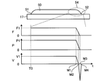
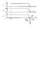
- FIG. 6 is a diagram for explaining the operation of the additional manufacturing apparatus 100 according to the first embodiment.
- FIG. 6 shows changes in the speed of the processing head 10, the output of the laser beam, and the speed of the wire 5 when the terminal end portion 54 of the bead 50 is formed.
- the vertical axis of the first graph is the speed F of the processing head 10
- the vertical axis of the second graph is the laser beam output P
- the vertical axis of the third graph is The speed V of the wire 5 is shown respectively.
- the horizontal axis of each graph represents time t.
- the additional manufacturing apparatus 100 starts decelerating the processing head 10, reducing the output of the laser beam, and decelerating the wire 5.
- the machining head 10 reaches the end point 52 at time M3 and stops at the end point 52.
- the output of the laser beam stops at time M3.
- the additional manufacturing apparatus 100 stops the feeding of the wire 5 at time M2 between time M1 and time M3. Further, the additional manufacturing device 100 starts pulling back the wire 5 at time M2.
- the speed of the wire 5 when the wire 5 is pulled back is decelerated after being accelerated from the time M2.
- the pulling back of the wire 5 stops at time M4 after time M3.
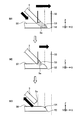
- FIG. 7 is a diagram illustrating a state of the laser beam 55 and the wire 5 in the additional manufacturing apparatus 100 shown in FIG.
- FIG. 7 shows a state of the laser beam 55 and the wire 5 when the end portion 54 of the bead 50 is formed.
- Each of “M1”, “M2”, and “M3” shown in FIG. 7 represents a state at time M1, time M2, and time M3 shown in FIG. 6, respectively.
- Deceleration of the movement of the machining head 10 in the X-axis direction is started at time M1. Also, at time M1, the output of the laser beam 55 starts to decrease. At time M1, the moving speed of the processing head 10 is F1, and the output of the laser beam 55 is P1. Further, deceleration of the speed at which the wire 5 is sent out is started at time M1. At time M1, the speed at which the wire 5 is delivered is V1. At time M1, the molten pool 53 occurs near the center of the laser beam 55 in the XY cross section. In the molten pool 53, the wire 5 and the bead 50 are fused and integrated. The tip 5a of the wire 5 has entered the molten bead 50. The boundary between the wire 5 and the bead 50 may not be clear. In FIG. 7, the boundary between the wire 5 and the bead 50 is schematically represented by a broken line.
- the position of the tip 5a is near the upper end of the molten pool 53.
- the wire 5 is in contact with the upper end of the molten pool 53, so to speak. Further, at time M2, the pulling back of the wire 5 is started. That is, the rotary motor 4 switches from the first drive to the second drive at time M2.
- the pulling back of the wire 5 is started from the state of being in contact with the upper end of the molten pool 53, so that the wire 5 is pulled back from the state of deeply entering the molten pool 53.
- the material adhering to the wire 5 from the molten pool 53 can be reduced.
- the additional manufacturing apparatus 100 can reduce deterioration of the shape accuracy of the terminal end portion 54. Further, the additional manufacturing apparatus 100 can reduce the formation of lumps at the tip 5a.
- the output of the laser beam 55 is stopped. Further, at time M3, the movement of the processing head 10 is stopped. Between the time M2 and the time M3, the wire 5 is pulled back and the machining head 10 moves while continuing to decelerate, whereby the position of the tip portion 5a is further retracted as compared with the time M2. As a result, the position of the tip portion 5a becomes a position outside the irradiation region of the laser beam 55. At time M3, the rotation motor 4 moves the tip 5a of the wire 5 to the outside of the irradiation area of the laser beam 55.
- the irradiation area at time M3 refers to the irradiation area up to immediately before time M3.
- the laser beam 55 that has been output until immediately before time M3 is indicated by a broken line.
- the output command generation unit 27 starts decreasing the output of the laser beam 55 at the first time point when the deceleration of the processing head 10 is started, and at the same time when the processing head 10 is stopped, the second output point is generated.
- An output command for stopping the output of the laser beam 55 is generated at the time point.
- the supply command generation unit 28 decelerates the delivery of the wire 5 at the first time point and pulls back the wire 5 from the delivery of the wire 5 at the third time point between the first time point and the second time point. Generate a supply command to switch to.
- the additional manufacturing apparatus 100 stops the feeding of the wire 5 and starts the pulling back of the wire 5 at time M2 while the output of the laser beam 55 is being reduced.
- the additional manufacturing apparatus 100 can reduce the formation of the lump due to the first factor by starting the pulling back of the wire 5 while the irradiation of the laser beam 55 is continued.
- the additional manufacturing apparatus 100 can shorten the time during which the laser beam 55 is continuously applied to the wire 5 by pulling back the wire 5 from the state in which the tip portion 5a is retracted to the upper end of the bead 50 at time M2. Therefore, the additional manufacturing apparatus 100 can reduce the formation of lumps due to the above second factor.
- the additional manufacturing apparatus 100 can reduce the sticking of the wire 5 to the bead 50 by stopping the feeding of the wire 5 before the irradiation of the laser beam 55 is stopped.
- the rotary motor 4 can retract the tip 5a of the wire 5 from the irradiation area of the laser beam 55 in a short time by performing the second drive that accelerates the speed of pulling back the wire 5 from the time M2. Thereby, the additional manufacturing apparatus 100 can further reduce the formation of lumps due to the second factor.
- the rotary motor 4 may perform a second drive in which the wire 5 is pulled back at a constant speed.
- FIG. 8 is a flowchart showing an operation procedure by the additional manufacturing apparatus 100 according to the first embodiment.
- step S1 the additional manufacturing apparatus 100 starts forming the bead 50 from the starting point 51 shown in FIG.
- step S2 the additional manufacturing apparatus 100 starts decelerating the movement of the processing head 10, reducing the output of the laser beam 55, and decelerating the feeding of the wire 5.
- Step S2 is a process at the time M1.
- step S3 the additional manufacturing apparatus 100 stops the feeding of the wire 5 and starts the pulling back of the wire 5 by switching the first drive to the second drive of the rotary motor 4.
- Step S3 is a process at time M2 described above.
- step S4 the additional manufacturing apparatus 100 stops the movement of the processing head 10 and stops the output of the laser beam 55.
- Step S4 is a process at time M3 described above.
- the additional manufacturing apparatus 100 ends the formation of one bead 50 in step S4.
- step S5 the additional manufacturing apparatus 100 stops the pullback of the wire 5 by stopping the second drive of the rotary motor 4.
- Step S5 is a process at time M4 described above.
- step S6 the additional manufacturing apparatus 100 determines whether or not there is a bead 50 to be formed next.
- step S6 Yes
- the additional manufacturing apparatus 100 moves the processing head 10 to a position which is the starting point 51 of the bead 50 to be formed next, in accordance with the processing program 20 in step S7. To move.
- the additional manufacturing apparatus 100 repeats the procedure from step S1 for the bead 50 to be formed next.
- step S6, No the additional manufacturing apparatus 100 ends the operation according to the procedure shown in FIG.
- the additive manufacturing apparatus 100 starts the first drive at the time between the time when the beam source starts decreasing the output and the time when the output of the beam source stops. Switching to the second drive is performed.
- the additive manufacturing apparatus 100 starts separating the wire 5 from the work piece at a time point between the time point when the beam source starts to decrease the output and the time point when the output of the beam source stops, so that the bead 50 is moved to the bead 50. It is possible to reduce the sticking of the wire 5 and the formation of the lump at the tip 5a of the wire 5.
- the additional manufacturing apparatus 100 can reduce the deterioration of processing quality due to the fixation of the wire 5 and the formation of the lump. Thereby, the additional manufacturing apparatus 100 has an effect that the processing quality can be improved.
- the beam may be a beam other than a laser beam, or may be an electron beam.
- the additional manufacturing apparatus 100 may include an electron beam generation source that is a beam source.
- the NC apparatus 1 can improve the processing quality even when the beam is a beam other than the laser beam.
- FIG. 9 is a diagram showing a functional configuration of the NC device 60 that controls the additional manufacturing device 100 according to the second embodiment of the present invention.
- the additional manufacturing apparatus 100 according to the second embodiment adjusts the time at which the drive unit switches from the first drive to the second drive based on the temperature of the workpiece.
- the same components as those in the above-described first embodiment are designated by the same reference numerals, and configurations different from the first embodiment will be mainly described.
- a signal from the temperature sensor 9 is input to the supply command generation unit 28.
- the supply command generation unit 28 adjusts the third time point based on the detection result of the temperature sensor 9 so that the third time point at which the first drive is switched to the second drive is the temperature of the workpiece. Adjust based on.
- FIG. 9 is the same as FIG. 2 except that an arrow indicating the transmission of a signal from the temperature sensor 9 to the supply command generation unit 28 is added.
- FIG. 10 is a diagram for explaining the operation of the additional manufacturing apparatus 100 according to the second embodiment.
- FIG. 10 shows changes in the output of the laser beam 55 and the speed of the wire 5 when the formation of the beads 50 is stopped.
- the time X1 is the first time point when the laser oscillator 2 starts decreasing the output from P1.
- Time point X2 is the second time point when the output of the laser beam 55 is stopped.
- Time M1 is a time point when the deceleration of the wire 5 is started.
- Time M2 is the third time point when the feeding of the wire 5 is stopped and the pulling back of the wire 5 is started.
- Time M3 is a time when the position of the tip portion 5a of the wire 5 becomes a position outside the irradiation region of the laser beam 55.
- Time M4 is the time when the pulling back of the wire 5 is stopped.
- FIG. 6 described above shows the operation when the time X1 matches the time M1 and the time X2 matches the time M3.
- the operation in such a case is referred to as a reference operation in the following description.
- the temperature detected by the temperature sensor 9 is referred to as the reference temperature. To do.
- the supply command generation unit 28 performs the adjustment to delay the third time point as compared with the case of the reference operation.
- the additional manufacturing apparatus 100 delays the laser beam 55 by delaying the third time point and the time point after the third time point and the position of the tip portion 5a is outside the irradiation area of the laser beam 55. Is pulled out, the wire 5 is pulled out.
- the additional manufacturing apparatus 100 can reduce the amount of heat received by the tip portion 5a of the wire 5 due to the irradiation of the laser beam 55, thereby reducing the formation of lumps due to the second factor.
- the supply command generation unit 28 may make an adjustment to delay the time point at which the deceleration of the feeding of the wire 5 is started after the time X1.
- the additional manufacturing apparatus 100 delays the time point when the deceleration of the wire 5 is started, the third time point, and the time point when the position of the tip 5a is outside the irradiation area of the laser beam 55. be able to.
- the supply command generation unit 28 makes an adjustment to advance the third time point as compared with the case of the reference operation.
- the additional manufacturing apparatus 100 hastens the laser beam 55 by advancing the third time point and the time point after the third time point, when the position of the tip portion 5a is outside the irradiation region of the laser beam 55. Is pulled out, the wire 5 is pulled out.
- the additive manufacturing apparatus 100 can reduce the amount of heat applied to the wire 5 by the irradiation of the laser beam 55, thereby reducing the sticking of the wire 5 to the bead 50.
- the supply command generation unit 28 may make adjustment so that the time point at which the deceleration of the feeding of the wire 5 is started is made earlier than the time X1.
- the additional manufacturing apparatus 100 advances the time point at which the deceleration of the wire 5 is started, the third time point, and the time point when the position of the tip 5a is outside the irradiation area of the laser beam 55. be able to.
- the supply command generation unit 28 may perform adjustment to advance the third time point earlier than the time X1 according to the detected degree of decrease in temperature.
- the additional manufacturing apparatus 100 may perform the adjustment at the third time point based on the temperature by the adjustment by the output instruction generator 27, instead of the adjustment by the supply instruction generator 28.
- the additional manufacturing apparatus 100 adjusts the third time point with respect to the first time point and the second time point by adjusting the time point at which the reduction of the laser output from P1 is started and the time point at which the laser output is stopped. be able to.
- the additional manufacturing apparatus 100 may adjust the third time point based on the temperature of the workpiece by detecting the temperature of the workpiece based on the image data from the camera 19.
- the additive manufacturing apparatus 100 can perform the adjustment at the third time point by using the existing configuration regardless of which of the detection result by the temperature sensor 9 and the image data from the camera 19 is used for the adjustment.
- the additional manufacturing apparatus 100 can reduce the number of parts as compared with the case where a configuration for adjustment at the third time point is separately required.
- the additional manufacturing apparatus 100 may be adjusted using a configuration other than the temperature sensor 9 or the camera 19. Such a configuration may be used only for the adjustment at the third time point.
- the additional manufacturing apparatus 100 may adjust the third time point based on the temperature detection result, or may adjust the third time point based on the workpiece temperature estimation result.
- the additive manufacturing apparatus 100 holds in advance information indicating the relationship between the number of beads 50 to be deposited and the temperature of the deposit 18, and adjusts the third time point based on the estimation result obtained from such information. You may.
- the additive manufacturing apparatus 100 adjusts the time when the drive unit switches from the first drive to the second drive based on the temperature of the workpiece including the molten pool 53. This can reduce the sticking of the wire 5 to the bead 50 and the formation of a lump at the tip 5a of the wire 5.
- the additional manufacturing apparatus 100 can reduce the deterioration of processing quality due to the fixation of the wire 5 and the formation of the lump. Thereby, the additional manufacturing apparatus 100 has an effect that the processing quality can be improved.
- FIG. 11 is a diagram showing a functional configuration of the NC device 70 that controls the additional manufacturing device 100 according to the third embodiment of the present invention.
- the additional manufacturing apparatus 100 according to the third embodiment adjusts the time when the drive unit switches from the first drive to the second drive based on the processing conditions.
- the same components as those in the above-described first and second embodiments are designated by the same reference numerals, and configurations different from those in the first and second embodiments will be mainly described.
- the condition setting unit 24 outputs the processing condition data to the supply command generation unit 28.
- the supply command generation unit 28 adjusts the third time point at which the first drive is switched to the second drive based on the processing conditions.
- FIG. 11 is the same as FIG. 2 except that an arrow indicating the transmission of data from the condition setting unit 24 to the supply command generation unit 28 is added.
- the transition of the output P and the transition of the speed V in the third embodiment are the same as the transition of the output P and the speed V in the second embodiment shown in FIG.
- the relationship between the transition of the output of the laser beam 55 and the transition of the speed of the wire 5 in the third embodiment will be described with reference to FIG. 10.
- the processing conditions when the bead 50 can be formed without causing the wire 5 to be fixed to the bead 50 and the formation of the lump at the tip portion 5a of the wire 5 by the reference operation are referred to as the reference processing conditions.
- the supply command generation unit 28 determines that the temperature of the workpiece is higher than the standard temperature in the adjustment in the second embodiment. Make the same adjustments as you did.
- the wire 5 when the wire 5 has a higher melting point than the wire 5 under the standard processing conditions or a wire 5 thicker than the wire 5 under the standard processing conditions is used, the wire 5 is less likely to melt than the wire under the standard processing conditions. Become.
- the supply command generation unit 28 performs the adjustment in the case where the temperature of the workpiece is lower than the standard temperature among the adjustments in the second embodiment. Make similar adjustments.
- the supply command generation unit 28 performs the same adjustment as the adjustment in the above-described second embodiment when the temperature of the workpiece is lower than the reference temperature.
- a laser beam 55 having a beam diameter larger than the beam diameter of the laser beam 55 under the standard processing conditions is used for processing, or a laser beam 55 having a higher output than the output of the laser beam 55 under the standard processing conditions is generated.
- the supply command generation unit 28 When used for processing, the supply command generation unit 28 performs the same adjustment as that performed when the temperature of the workpiece is higher than the reference temperature among the adjustments in the second embodiment. As a result, the additional manufacturing apparatus 100 can reduce the sticking of the wire 5 and the formation of the lump at the tip 5a of the wire 5, as in the second embodiment.
- the additional manufacturing apparatus 100 may adjust the third time point according to the number of the beads 50 accumulated.
- the temperature of the bead 50 being formed easily decreases due to heat dissipation from the bead 50 to the base material 17.
- the beads 50 of the second and subsequent layers are formed under the same processing conditions as in the case of the first layer, the larger the number of the beads 50 that are deposited, the less likely it is that heat is radiated from the deposit 18. In this case, since the heat accumulated in the deposit 18 increases, the temperature of the formed bead 50 is less likely to decrease.
- the additional manufacturing apparatus 100 adjusts to delay the third time point as the number of the deposited beads 50 increases because the wire 5 is more likely to melt as the number of the deposited beads 50 increases. As a result, the additional manufacturing apparatus 100 can reduce the formation of lumps at the tip 5a of the wire 5, as in the second embodiment.
- the additional manufacturing apparatus 100 may perform the adjustment at the third time point based on the processing condition by the adjustment by the output instruction generator 27 instead of the adjustment by the supply instruction generator 28.
- the additive manufacturing apparatus 100 may perform the adjustment at the third time point based on the temperature of the work piece as in the second embodiment, in addition to the adjustment at the third time point based on the processing condition.
- the additional manufacturing apparatus 100 adjusts the time point at which the drive unit switches from the first drive to the second drive, based on the processing conditions, so as to the second embodiment.
- the adhesion of the wire 5 to the bead 50 and the formation of a lump at the tip 5a of the wire 5 can be reduced.
- the additional manufacturing apparatus 100 has an effect that the processing quality can be improved.
- FIG. 12 is a diagram for explaining the operation of the additional manufacturing apparatus 100 according to the fourth embodiment of the present invention.
- the additional manufacturing apparatus 100 according to the fourth embodiment moves the processing head 10 in a direction away from the workpiece before the time when the drive unit switches the first drive to the second drive.
- the same components as those in the first to third embodiments are designated by the same reference numerals, and configurations different from those in the first to third embodiments will be mainly described.
- the transition of the output P and the transition of the speed V in the fourth embodiment are the same as the transition of the output P and the speed V in the second embodiment shown in FIG.
- the movement of the processing head 10 in the direction away from the work piece is performed at time M1 when the deceleration of the feeding of the wire 5 is started, and when the feeding of the wire 5 is stopped and the pulling back of the wire 5 is started. It is performed at the fourth time point between time M2, which is time point 3 of FIG. In FIG. 12, the direction away from the workpiece is the plus Z direction.
- the fourth time point may be the same as the time point M1. Further, the fourth time point is a time point before the third time point.
- FIG. 12 shows a state before the machining head 10 is moved in the plus Z direction and a state after the machining head 10 is moved in the plus Z direction.
- the tip portion 5a of the wire 5 has deeply entered the molten pool 53 as in the state at time M1 shown in FIG. From this state, the additional manufacturing apparatus 100 moves the processing head 10 in the plus Z direction by the distance ⁇ Z at the fourth time point.
- the position of the tip portion 5a of the wire 5 is raised by the distance ⁇ Z in the plus Z direction from the position at the time of processing along with the movement of the processing head 10, and becomes the position near the upper end of the molten pool 53.
- the axis command generation unit 23 generates an axis command for moving the machining head 10 in the plus Z direction by the distance ⁇ Z at the fourth time point.
- the head drive unit 14 moves the machining head 10 in a direction away from the workpiece at the fourth time point according to the axis command.
- the wire 5 is in contact with the upper end of the molten pool 53, so to speak.
- the pulling back of the wire 5 is started.
- the pulling back of the wire 5 is started from the state of being in contact with the upper end of the molten pool 53, so that the wire 5 is pulled back from the state of deeply entering the molten pool 53.
- the material adhering to the wire 5 from the molten pool 53 can be reduced.
- the additional manufacturing apparatus 100 can reduce deterioration of the shape accuracy of the terminal end portion 54. Further, the additional manufacturing apparatus 100 can reduce the formation of lumps at the tip 5a of the wire 5.
- the additional manufacturing apparatus 100 may perform the adjustment at the third time point based on the temperature of the work piece as in the second embodiment.
- the additional manufacturing apparatus 100 may perform the adjustment at the third time point based on the processing conditions as in the third embodiment.
- the additive manufacturing apparatus 100 moves the machining head 10 in a direction away from the workpiece before the drive unit switches the first drive to the second drive, thereby terminating the end portion.
- the deterioration of the shape accuracy in 54 can be reduced.
- the additional manufacturing apparatus 100 can reduce the formation of lumps at the tip 5a of the wire 5. Thereby, the additional manufacturing apparatus 100 has an effect that the processing quality can be improved.
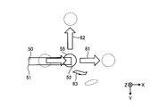
- FIG. 13 is a diagram for explaining the operation of the additional manufacturing apparatus 100 according to the fifth embodiment of the present invention.
- the additive manufacturing apparatus 100 according to the fifth embodiment changes the relative position of the processing head 10 with respect to the workpiece by moving the processing head 10 or rotating the workpiece at a position where the addition of the melted material is stopped. .
- the position where the addition of the melted material is stopped is the position where the end point 52 of the bead 50 is reached.
- the same components as those in the first to fourth embodiments are designated by the same reference numerals, and configurations different from those in the first to fourth embodiments will be mainly described.
- the first movement direction 81 that is the plus X direction and the second movement direction 82 that is the minus Y direction are the machining head 10 when the machining head 10 reaches the end point 52 of the bead 50.
- the rotation direction 83 is an example of the direction in which the workpiece is rotated by the drive of the rotation drive unit 16 when the processing head 10 reaches the position that is the end point 52 of the bead 50.
- the rotation direction 83 is a direction in which the relative distance between the workpiece and the tip portion 5a increases.
- the transition of the output P and the transition of the speed V in the fifth embodiment are the same as the transition of the output P and the speed V in the second embodiment shown in FIG.
- the movement of the processing head 10 and the rotation of the workpiece will be described with reference to FIG.
- the processing head 10 moves at the time M2 in the plus X direction, which is the same direction as the movement direction when the bead 50 is formed.
- the processing head 10 stops moving in the plus X direction and starts moving in the minus Y direction at time M2. .
- the axis command generation unit 23 which is the second command generation unit, generates an axis command that moves the machining head 10 in a preset direction at the position that is the end point 52.
- the head drive unit 14 moves the processing head 10 according to the axis command.
- the machining head 10 stops moving in the plus X direction.
- the rotation drive unit 16 rotates the workpiece in the rotation direction 83.
- the axis command generator 23 generates a rotation command to rotate the work piece in a preset direction at the position of the end point 52.
- the rotation driving unit 16 rotates the stage 15 according to the rotation command.
- the additional manufacturing apparatus 100 changes the relative position of the processing head 10 with respect to the workpiece when the wire 5 is pulled back to the wire spool 6.
- the additional manufacturing apparatus 100 can adjust the shape left at the terminal end portion 54 of the bead 50 to a shape suitable for processing a molded product. As a result, the additional manufacturing apparatus 100 can improve the shape accuracy.
- the direction in which the processing head 10 is moved and the direction in which the workpiece is rotated are not limited to those shown in FIG. 13 and may be arbitrary.
- the change in the relative position of the processing head 10 with respect to the workpiece does not have to be simultaneous with the switching from the first drive to the second drive by the drive unit.
- the additional manufacturing apparatus 100 may change the relative position of the processing head 10 with respect to the workpiece before the switching, and may change the relative position of the processing head 10 with respect to the workpiece after the switching. .
- the additional manufacturing apparatus 100 may not pull back the wire 5 by the rotary motor 4, but may pull back the wire 5 by moving the processing head 10.
- the pulling back of the wire 5 by the movement of the processing head 10 means a state in which the tip 5a is relatively separated from the workpiece toward the wire spool 6 by changing the relative position of the processing head 10 with respect to the workpiece. It means that.
- the rotary motor 4 functions as a drive unit that performs the first drive for feeding the material from the supply source toward the workpiece.
- the head drive unit 14 functions as a drive unit that performs a second drive for returning the fed material to the supply source.
- the rotary motor 4 and the head drive unit 14 switch from the first drive to the second drive based on the machining program.
- the first drive refers to feeding the wire 5 from the wire spool 6 toward the workpiece by the rotary motor 4.
- the second driving refers to moving the processing head 10 in order to change the relative position by the head driving unit 14. Also in this case, the additional manufacturing apparatus 100 can improve the shape accuracy and the processing quality.
- the additional manufacturing apparatus 100 may not pull back the wire 5 by the rotary motor 4, but may pull back the wire 5 by rotating the workpiece.
- the pulling back of the wire 5 due to the rotation of the workpiece means that the tip 5a is relatively pulled away from the workpiece toward the wire spool 6 by changing the relative position of the processing head 10 with respect to the workpiece. It means that.
- the rotary motor 4 functions as a drive unit that performs the first drive for feeding the material from the supply source toward the workpiece.
- the rotation drive unit 16 functions as a drive unit that performs a second drive for returning the fed material to the supply source.
- the rotary motor 4 and the rotary drive unit 16 switch from the first drive to the second drive based on the machining program.
- the first drive refers to feeding the wire 5 from the wire spool 6 toward the workpiece by the rotary motor 4.
- the second drive means that the rotation drive unit 16 rotates the workpiece in order to change the relative position by the rotation drive unit 16. Also in this case, the additional manufacturing apparatus 100 can improve the shape accuracy and the processing quality.
- the additional manufacturing apparatus 100 may change the relative position according to the fifth embodiment in addition to moving the machining head 10 in the plus Z direction according to the fourth embodiment.
- the additive manufacturing apparatus 100 may perform the adjustment at the third time point based on the temperature of the workpiece as in the second embodiment.
- the additional manufacturing apparatus 100 may perform the adjustment at the third time point based on the processing conditions as in the third embodiment.
- the addition manufacturing apparatus 100 can improve the shape accuracy by changing the relative position of the processing head 10 with respect to the workpiece at the position where the addition of the melted material is stopped. Thereby, the additional manufacturing apparatus 100 has an effect that the processing quality can be improved.
- FIG. 14 is a diagram for explaining the operation of the additional manufacturing apparatus 100 according to the sixth embodiment of the present invention.
- the additional manufacturing apparatus 100 according to the sixth embodiment keeps the output of the laser beam 55 constant during the period including the time point when the drive unit switches from the first drive to the second drive.
- the same components as those in the first to fifth embodiments are designated by the same reference numerals, and configurations different from those in the first to fifth embodiments will be mainly described.
- the decrease in the output of the laser beam 55 starts from time M1.
- the output of the laser beam 55 reaches a preset output value L1 before the time M2.
- L1 is an output value lower than P1 and higher than zero.
- the output of the laser beam 55 is maintained at L1 from the time when it reaches L1 to the time M3.
- L1 is an output value capable of maintaining the molten state of the molten pool 53 to the extent that the wire 5 can be separated from the bead 50.
- the output of the laser beam 55 decreases again from time M3 and reaches zero. In this way, the additional manufacturing apparatus 100 makes the output of the laser beam 55 constant during the period including the time M2 that is the third time point. Due to the above operation, the output command generation unit 27 generates an output command that causes the output to reach L1 before time M2 and sets the output to L1 until time M3.
- the additional manufacturing apparatus 100 can pull back the wire 5 from the molten pool 53 in the molten state by irradiating the laser beam 55 of L1 during the period including the third time point.
- the additive manufacturing apparatus 100 can reduce sticking of the wire 5 to the bead 50 by bringing the molten pool 53 into a molten state.
- the additional manufacturing apparatus 100 only needs to be able to bring the molten pool 53 into the molten state while the wire 5 is pulled back, and may appropriately change the length of the period for keeping the output value constant.
- the additional manufacturing apparatus 100 may start decreasing the output from L1 before the time M3.
- L1 may be set based on the detection result of the temperature of the workpiece.
- L1 may be adjusted based on how easily the wire 5 melts.
- the additional manufacturing apparatus 100 may perform the adjustment at the third time point based on the temperature of the work piece as in the second embodiment.
- the additional manufacturing apparatus 100 may perform the adjustment at the third time point based on the processing conditions as in the third embodiment.
- the additional manufacturing apparatus 100 may move the processing head 10 similarly to the fourth embodiment.
- the additional manufacturing apparatus 100 may move the processing head 10 or rotate the workpiece as in the fifth embodiment.
- the additive manufacturing apparatus 100 causes the beads 50 to move to the bead 50 by keeping the output of the laser beam 55 constant during the period including the time point when the driving unit switches from the first driving to the second driving.
- the sticking of the wire 5 can be reduced.
- the additional manufacturing apparatus 100 has an effect that the processing quality can be improved.
Abstract
An additive manufacturing device (100) is provided with a laser oscillator (2) which is a beam source for outputting a beam, and a rotating motor (4) which is a drive unit for changing the relative positions of a material fed out of a wire spool (6) serving as a supply source of a wire (5) that is the material, and an object to be processed. The drive unit is capable of performing a first drive for feeding the material out of the supply source toward the object to be processed, and a second drive for turning the material that has been fed out back to the supply source, wherein switching from the first drive to the second drive is performed on the basis of a processing program.
Description
本発明は、被加工物へ材料を付加して造形物を製造する付加製造装置および付加製造装置を制御する数値制御装置に関する。
The present invention relates to an additional manufacturing apparatus that adds a material to a workpiece to manufacture a modeled object and a numerical control apparatus that controls the additional manufacturing apparatus.
指向性エネルギ堆積(Direct Energy Deposition:DED)方式によって立体形状の造形物を製造する付加製造装置が知られている。付加製造装置には、加工ヘッドから出射するビームによって局所的に材料を溶融させ、溶融させた材料を被加工物へ付加することによって造形物を製造するものがある。
An additional manufacturing device is known that manufactures a three-dimensional shaped object by the Direct Energy Deposition (DED) method. Some additional manufacturing apparatuses manufacture a modeled object by locally melting a material with a beam emitted from a processing head and adding the melted material to a workpiece.
材料として金属材料のワイヤが使用される付加製造装置は、ビームの照射位置へワイヤを供給しながら照射位置を移動させることによって、溶融した金属材料の凝固物である線状のビードを形成する。付加製造装置は、ビードの形成が停止される終端部において、ビードへワイヤが固着する以前に、材料が溶融している状態のうちに被加工物からワイヤを退避させる。
An additional manufacturing apparatus that uses a wire of a metal material as a material moves the irradiation position while supplying the wire to the irradiation position of the beam to form a linear bead, which is a solidified material of the molten metal material. The additional manufacturing apparatus retracts the wire from the workpiece while the material is molten before the wire is fixed to the bead at the end portion where the bead formation is stopped.
特許文献1には、金属材料へワイヤを供給しながらレーザ光を照射することによって金属材料を溶接する方法において、溶接部の終端部にてワイヤの供給を徐々に遅くさせながらレーザ光の焦点を溶接部から離間させてからレーザ光の照射を停止させることが開示されている。
Patent Document 1 discloses a method of welding a metal material by irradiating the metal material with a laser beam while supplying the wire with the laser beam, while gradually delaying the supply of the wire at the terminal end of the welded portion. It is disclosed that the irradiation of the laser beam is stopped after the laser beam is separated from the welded portion.
付加製造装置において、上記の特許文献1にかかる従来の技術と同様に終端部から焦点を離間させてからビームを停止させる場合、ビードの形成が停止されてワイヤの供給を遅くさせている間においてもワイヤの先端部へのビームの照射が継続される。先端部では、ビームの照射によってワイヤが溶融し、溶融したワイヤがその後硬化する。このような溶融と硬化とを経て、先端部には、ワイヤのうち先端部以外の部分よりも拡張された幅を持つ塊が形成されることがある。このような塊がワイヤに形成されると、塊が残されたワイヤを使用して次の付加が開始されることになるため、造形物の形状に影響を及ぼすことがある。付加の停止から付加の開始までの間にワイヤから塊を切除することとした場合、付加製造装置では、造形物の製造に要する工程が増加することになり、切除後の塊が付加製造装置内に滞留するという問題も生じる。上記の従来の技術によると、付加製造装置は、ビードへのワイヤの固着を低減可能である一方、ワイヤの先端部に塊が形成されることによる加工品質の低下が問題となる。
In the additional manufacturing apparatus, when the beam is stopped after the focal point is separated from the terminal end similarly to the conventional technique according to Patent Document 1, while the bead formation is stopped and the wire supply is delayed, The irradiation of the beam to the tip of the wire is continued. At the tip, the irradiation of the beam melts the wire, and the melted wire is subsequently cured. Through such melting and hardening, a lump having a width wider than that of a portion of the wire other than the tip may be formed at the tip. When such a lump is formed on the wire, the shape of the shaped article may be affected because the wire having the lump left is used to start the next addition. If it is decided to cut out the lump from the wire between the time when the addition is stopped and the time when the addition is started, the additional manufacturing equipment will increase the number of steps required to manufacture the modeled object, and the lump after the cutting will be removed inside the additional manufacturing equipment. There is also a problem of staying in the room. According to the above-mentioned conventional technique, the additive manufacturing apparatus can reduce the sticking of the wire to the bead, but on the other hand, there is a problem in that the processing quality is deteriorated due to the formation of a lump at the tip of the wire.
本発明は、上記に鑑みてなされたものであって、加工品質の向上を可能とする付加製造装置を得ることを目的とする。
The present invention has been made in view of the above, and an object of the present invention is to obtain an additional manufacturing apparatus capable of improving processing quality.
上述した課題を解決し、目的を達成するために、本発明にかかる付加製造装置は、ビームの照射によって溶融させた材料を被加工物へ付加して造形物を製造する。本発明にかかる付加製造装置は、ビームを出力するビーム源と、材料の供給源から送り出された材料と被加工物との相対位置を変化させる駆動部と、を備える。駆動部は、供給源から被加工物へ向けて材料を送り出すための第1の駆動と送り出された材料を供給源へ引き戻すための第2の駆動とが可能であって、かつ、加工プログラムに基づいて第1の駆動から第2の駆動への切り換えを行う。
In order to solve the above-mentioned problems and achieve the object, the additive manufacturing apparatus according to the present invention adds a material melted by irradiation of a beam to a workpiece to manufacture a modeled object. An additional manufacturing apparatus according to the present invention includes a beam source that outputs a beam, and a drive unit that changes a relative position between a material sent from a material supply source and a workpiece. The drive unit is capable of performing a first drive for feeding the material from the supply source toward the workpiece and a second drive for pulling the fed material back to the supply source, Based on this, switching from the first drive to the second drive is performed.
本発明にかかる付加製造装置は、加工品質の向上が可能となるという効果を奏する。
The additional manufacturing apparatus according to the present invention has the effect of improving the processing quality.
以下に、本発明の実施の形態にかかる付加製造装置および数値制御装置を図面に基づいて詳細に説明する。なお、この実施の形態によりこの発明が限定されるものではない。以下の説明では、数値制御装置をNC(Numerical Control)装置と称することがある。
Below, an additional manufacturing apparatus and a numerical control apparatus according to an embodiment of the present invention will be described in detail with reference to the drawings. The present invention is not limited to this embodiment. In the following description, the numerical control device may be referred to as an NC (Numerical Control) device.
実施の形態1.
図1は、本発明の実施の形態1にかかる付加製造装置100を示す図である。付加製造装置100は、ビームの照射によって溶融させた材料を被加工物へ付加する付加加工によって造形物を製造する工作機械である。実施の形態1において、ビームはレーザビームであって、材料は金属材料のワイヤ5であるものとする。Embodiment 1.
FIG. 1 is a diagram showing anadditional manufacturing apparatus 100 according to the first embodiment of the present invention. The additive manufacturing apparatus 100 is a machine tool that manufactures a modeled object by an additive process of adding a material melted by beam irradiation to a workpiece. In the first embodiment, the beam is a laser beam and the material is the wire 5 made of a metallic material.
図1は、本発明の実施の形態1にかかる付加製造装置100を示す図である。付加製造装置100は、ビームの照射によって溶融させた材料を被加工物へ付加する付加加工によって造形物を製造する工作機械である。実施の形態1において、ビームはレーザビームであって、材料は金属材料のワイヤ5であるものとする。
FIG. 1 is a diagram showing an
付加製造装置100は、ベース材17にビードを堆積させることによって、金属材料による堆積物18をベース材17の表面に形成する。ビードは、溶融したワイヤ5が凝固することによって形成される線状の物体である。ベース材17は、ステージ15に置かれる。以下の説明において、被加工物とは、ベース材17と堆積物18とを指すものとする。造形物とは、加工プログラムにしたがった材料の付加を終えた後のベース材17と堆積物18とを指すものとする。図1に示すベース材17は板材である。ベース材17は、板材以外のものであっても良い。
The additive manufacturing apparatus 100 forms beads 18 on the base material 17 to form a deposit 18 made of a metal material on the surface of the base material 17. The bead is a linear object formed by solidifying the molten wire 5. The base material 17 is placed on the stage 15. In the following description, the work piece refers to the base material 17 and the deposit 18. The modeled object refers to the base material 17 and the deposit 18 after the addition of the material according to the processing program is completed. The base material 17 shown in FIG. 1 is a plate material. The base material 17 may be something other than a plate material.
付加製造装置100は、ビームノズル11とワイヤノズル12とガスノズルとを有する加工ヘッド10を備える。ビームノズル11は、材料を溶融させるレーザビームを、被加工物へ向けて出射する。ワイヤノズル12は、被加工物におけるレーザビームの照射位置へ向けてワイヤ5を進行させる。ガスノズルは、堆積物18の酸化抑制およびビードの冷却のためのガスを被加工物へ向けて噴出する。図1では、ガスノズルの図示を省略している。また、加工ヘッド10には、温度センサ9とカメラ19とが設けられている。
The additional manufacturing apparatus 100 includes a processing head 10 having a beam nozzle 11, a wire nozzle 12, and a gas nozzle. The beam nozzle 11 emits a laser beam that melts a material toward a workpiece. The wire nozzle 12 advances the wire 5 toward the irradiation position of the laser beam on the workpiece. The gas nozzle ejects a gas for suppressing the oxidation of the deposit 18 and cooling the bead toward the workpiece. In FIG. 1, the illustration of the gas nozzle is omitted. Further, the processing head 10 is provided with a temperature sensor 9 and a camera 19.
ビーム源であるレーザ発振器2は、レーザビームを発振する。レーザ発振器2からのレーザビームは、光伝送路であるファイバーケーブル3を通ってビームノズル11へ伝搬する。ガス供給装置7は、配管8を通じてガスノズルへガスを供給する。ガスノズルは、ビームノズル11から出射されるレーザビームの中心軸に沿うようにガスを噴出する。すなわち、ビームノズル11とガスノズルとは、同軸上に配置されている。なお、ガスノズルは、ビームノズル11と同軸上の位置以外の位置に設けられていても良い。
The laser oscillator 2, which is a beam source, oscillates a laser beam. The laser beam from the laser oscillator 2 propagates to the beam nozzle 11 through the fiber cable 3 which is an optical transmission line. The gas supply device 7 supplies gas to the gas nozzle through the pipe 8. The gas nozzle ejects gas along the central axis of the laser beam emitted from the beam nozzle 11. That is, the beam nozzle 11 and the gas nozzle are coaxially arranged. The gas nozzle may be provided at a position other than the position coaxial with the beam nozzle 11.
ワイヤ5が巻き付けられているワイヤスプール6は、材料の供給源である。回転モータ4は、材料の供給のための供給駆動部である。サーボモータである回転モータ4の回転駆動に伴って、ワイヤスプール6は回転する。回転モータ4は、ワイヤスプール6から被加工物へ向けてワイヤ5を送り出すための第1の駆動と、送り出されたワイヤ5をワイヤスプール6へ引き戻すための第2の駆動とを行う。回転モータ4は、第1の駆動によりワイヤスプール6を第1の方向へ回転させ、第2の駆動によりワイヤスプール6を第1の方向とは逆の第2の方向へ回転させる。図1において、第1の方向は反時計回りの方向であり、第2の方向は時計回りの方向である。回転モータ4は、加工プログラムに基づいて第1の駆動から第2の駆動への切り換えを行う。回転モータ4は、第1の駆動から第2の駆動への切り換えによって、ワイヤスプール6から送り出されたワイヤ5の先端部と被加工物との相対位置を変化させる。
The wire spool 6 around which the wire 5 is wound is a material supply source. The rotary motor 4 is a supply drive unit for supplying the material. The wire spool 6 rotates as the rotary motor 4, which is a servo motor, is driven to rotate. The rotary motor 4 performs a first drive for feeding the wire 5 from the wire spool 6 toward the workpiece, and a second drive for pulling the fed wire 5 back to the wire spool 6. The rotary motor 4 rotates the wire spool 6 in the first direction by the first drive, and rotates the wire spool 6 in the second direction opposite to the first direction by the second drive. In FIG. 1, the first direction is the counterclockwise direction and the second direction is the clockwise direction. The rotary motor 4 switches from the first drive to the second drive based on the machining program. The rotary motor 4 changes the relative position between the tip of the wire 5 sent from the wire spool 6 and the workpiece by switching from the first drive to the second drive.
ワイヤスプール6から送り出されたワイヤ5は、ワイヤノズル12を通されて、レーザビームの照射位置へ供給される。なお、ワイヤノズル12には、ワイヤスプール6からワイヤ5を引き出すための動作機構が設けられても良い。付加製造装置100は、ワイヤスプール6に連結される回転モータ4とワイヤノズル12の動作機構との少なくとも一方が設けられることによって、レーザビームの照射位置へワイヤ5を供給可能とする。かかる動作機構は、材料の供給のための供給駆動部である。図1では、ワイヤノズル12の動作機構の図示を省略している。
The wire 5 sent from the wire spool 6 is passed through the wire nozzle 12 and supplied to the laser beam irradiation position. The wire nozzle 12 may be provided with an operation mechanism for pulling out the wire 5 from the wire spool 6. The additional manufacturing apparatus 100 is provided with at least one of the rotation motor 4 connected to the wire spool 6 and the operation mechanism of the wire nozzle 12, so that the wire 5 can be supplied to the irradiation position of the laser beam. Such an operating mechanism is a feeding drive for feeding the material. In FIG. 1, the illustration of the operation mechanism of the wire nozzle 12 is omitted.
ヘッド駆動部14は、X軸方向、Y軸方向およびZ軸方向の各方向へ加工ヘッド10を移動させる。X軸、Y軸およびZ軸は、互いに垂直な3軸である。X軸およびY軸は、水平方向に平行な軸である。Z軸方向は、鉛直方向である。なお、X軸方向のうち図中矢印で示す方向をプラスX方向、プラスX方向とは逆の方向をマイナスX方向と称することがある。Y軸方向のうち図中矢印で示す方向をプラスY方向、プラスY方向とは逆の方向をマイナスY方向と称することがある。Z軸方向のうち図中矢印で示す方向をプラスZ方向、プラスZ方向とは逆の方向をマイナスZ方向と称することがある。プラスZ方向は鉛直上方向である。マイナスZ方向は鉛直下方向である。
The head drive unit 14 moves the processing head 10 in each of the X-axis direction, the Y-axis direction, and the Z-axis direction. The X axis, the Y axis, and the Z axis are three axes that are perpendicular to each other. The X axis and the Y axis are axes parallel to the horizontal direction. The Z-axis direction is the vertical direction. Of the X-axis directions, the direction indicated by the arrow in the figure may be referred to as the plus X direction, and the direction opposite to the plus X direction may be referred to as the minus X direction. Of the Y-axis directions, the direction indicated by the arrow in the figure may be referred to as the plus Y direction, and the direction opposite to the plus Y direction may be referred to as the minus Y direction. Of the Z-axis directions, the direction indicated by the arrow in the figure may be referred to as the plus Z direction, and the direction opposite to the plus Z direction may be referred to as the minus Z direction. The plus Z direction is the vertically upward direction. The minus Z direction is the vertically downward direction.
ヘッド駆動部14は、X軸方向への加工ヘッド10の移動のための動作機構を構成するサーボモータと、Y軸方向の加工ヘッド10の移動のための動作機構を構成するサーボモータと、Z軸方向への加工ヘッド10の移動のための動作機構を構成するサーボモータとを有する。ヘッド駆動部14は、3軸のそれぞれの方向の並進運動を可能とする動作機構である。図1では、各サーボモータの図示を省略している。付加製造装置100は、ヘッド駆動部14の駆動によって加工ヘッド10を移動させることで、被加工物におけるレーザビームの照射位置を移動させる。
The head drive unit 14 includes a servo motor that constitutes an operating mechanism for moving the machining head 10 in the X-axis direction, a servo motor that constitutes an operating mechanism for moving the machining head 10 in the Y-axis direction, and a Z And a servo motor constituting an operation mechanism for moving the machining head 10 in the axial direction. The head drive unit 14 is an operation mechanism that enables translational movement in each of the three axes. In FIG. 1, the illustration of each servo motor is omitted. The additional manufacturing apparatus 100 moves the processing head 10 by driving the head driving unit 14 to move the irradiation position of the laser beam on the workpiece.
図1に示す加工ヘッド10では、ビームノズル11からマイナスZ方向へレーザビームを進行させる。ワイヤノズル12は、XY面内においてビームノズル11とは離れた位置に設けられており、Z軸に対して斜めの方向へワイヤ5を進行させる。この他、加工ヘッド10は、ビームノズル11から出射されるレーザビームの中心軸に沿うようにワイヤ5を進行させることとしても良い。すなわち、ビームノズル11とワイヤノズル12とが互いに同軸上に配置されていても良い。ビームノズル11は、ワイヤ5を中心とするリング状にビーム断面の形状が調整されたレーザビーム、あるいはワイヤ5を中心としてワイヤ5の周囲に分散させた複数のビームを出射しても良い。かかるレーザビームは、被加工物の照射位置にて収束するように調整される。
In the processing head 10 shown in FIG. 1, the laser beam is advanced from the beam nozzle 11 in the minus Z direction. The wire nozzle 12 is provided at a position apart from the beam nozzle 11 in the XY plane and advances the wire 5 in a direction oblique to the Z axis. In addition, the processing head 10 may move the wire 5 along the central axis of the laser beam emitted from the beam nozzle 11. That is, the beam nozzle 11 and the wire nozzle 12 may be arranged coaxially with each other. The beam nozzle 11 may emit a laser beam whose beam cross-sectional shape is adjusted in a ring shape with the wire 5 as the center, or a plurality of beams dispersed around the wire 5 with the wire 5 as the center. The laser beam is adjusted so as to converge at the irradiation position of the workpiece.
回転駆動部16は、2軸のそれぞれを中心とする回転運動を可能とする動作機構である。回転駆動部16は、Z軸周りにステージ15を回転させるための動作機構を構成するサーボモータと、X軸周りにステージ15を回転させるための動作機構を構成するサーボモータとを有する。図1では、各サーボモータの図示を省略している。回転駆動部16は、ステージ15とともに被加工物を回転させる。付加製造装置100は、回転駆動部16によってステージ15を回転させることで、被加工物の姿勢を加工に適した姿勢にさせることができる。
The rotary drive unit 16 is an operating mechanism that enables rotary motion about each of the two axes. The rotation drive unit 16 has a servo motor that constitutes an operating mechanism for rotating the stage 15 around the Z axis, and a servo motor that constitutes an operating mechanism for rotating the stage 15 around the X axis. In FIG. 1, the illustration of each servo motor is omitted. The rotation drive unit 16 rotates the workpiece together with the stage 15. The additional manufacturing apparatus 100 can rotate the stage 15 by the rotation driving unit 16 to make the posture of the workpiece suitable for machining.
温度センサ9は、被加工物上にて溶融している材料が溜められている溶融池を含めた被加工物の温度を検出する。カメラ19は、溶融池の画像を撮影する。付加製造装置100は、温度センサ9による検出結果を基に、加工条件を調整する。付加製造装置100は、カメラ19での撮影によって得られた画像データを基に、溶融池の状態をモニタしながら加工を行うことができる。
The temperature sensor 9 detects the temperature of the work piece including the molten pool in which the material melted on the work piece is stored. The camera 19 captures an image of the molten pool. The additional manufacturing apparatus 100 adjusts the processing conditions based on the detection result of the temperature sensor 9. The additional manufacturing apparatus 100 can perform processing while monitoring the state of the molten pool based on the image data obtained by photographing with the camera 19.
NC装置1は、加工プログラムに従って付加製造装置100を制御する。NC装置1は、ヘッド駆動部14へ軸指令を出力することによって、ヘッド駆動部14を制御する。NC装置1は、レーザ発振器2へ出力指令を出力することによって、レーザ発振器2によるレーザ発振を制御する。出力指令は、レーザビームの出力の制御のための第1の指令である。
The NC device 1 controls the additional manufacturing device 100 according to a processing program. The NC device 1 controls the head drive unit 14 by outputting an axis command to the head drive unit 14. The NC device 1 controls laser oscillation by the laser oscillator 2 by outputting an output command to the laser oscillator 2. The output command is the first command for controlling the output of the laser beam.
NC装置1は、回転モータ4へ供給指令を出力することによって、回転モータ4を制御する。供給指令は、第1の駆動と第2の駆動とを制御するための第2の指令である。NC装置1は、第1の駆動を制御することによって、ワイヤスプール6から被加工物へ向けて送り出されるワイヤ5の速度を調整する。また、NC装置1は、第2の駆動を制御することによって、被加工物からワイヤスプール6へ向けて引き戻されるワイヤ5の速度を調整する。かかる速度を、走行速度を称することがある。ワイヤスプール6からワイヤ5が送り出されるときにおける走行速度は、時間当たりの材料の供給量を表す。
The NC device 1 controls the rotary motor 4 by outputting a supply command to the rotary motor 4. The supply command is a second command for controlling the first drive and the second drive. The NC device 1 controls the first drive to adjust the speed of the wire 5 sent from the wire spool 6 toward the workpiece. Further, the NC device 1 adjusts the speed of the wire 5 pulled back from the workpiece toward the wire spool 6 by controlling the second drive. Such speed may be referred to as traveling speed. The traveling speed when the wire 5 is delivered from the wire spool 6 represents the supply amount of the material per hour.
NC装置1は、ガスの供給量の条件に応じた指令をガス供給装置7へ出力することによって、ガス供給装置7からガスノズルへのガスの供給量を制御する。NC装置1は、回転駆動部16へ回転指令を出力することによって、回転駆動部16の駆動を制御する。
The NC device 1 controls the gas supply amount from the gas supply device 7 to the gas nozzle by outputting a command according to the gas supply amount condition to the gas supply device 7. The NC device 1 controls the drive of the rotation drive unit 16 by outputting a rotation command to the rotation drive unit 16.
温度センサ9は、温度の検出結果を示す信号をNC装置1へ出力する。カメラ19は、撮影によって得られた画像データをNC装置1へ出力する。NC装置1は、温度の検出結果と画像データとを基に、加工条件を調整する。なお、NC装置1は、付加製造装置100の構成要素の1つであっても良く、付加製造装置100の外部の装置であっても良い。
The temperature sensor 9 outputs a signal indicating the temperature detection result to the NC device 1. The camera 19 outputs the image data obtained by shooting to the NC device 1. The NC device 1 adjusts the processing conditions based on the temperature detection result and the image data. The NC device 1 may be one of the constituent elements of the additional manufacturing device 100, or may be a device external to the additional manufacturing device 100.
図2は、図1に示す付加製造装置100を制御するNC装置1の機能構成を示す図である。NC装置1には、コンピュータ支援製造(Computer Aided Manufacturing:CAM)装置によって作成されたNCプログラムである加工プログラム20が入力される。加工プログラム20は、ステージ15に置かれた被加工物に対して加工ヘッド10を移動させる移動経路の指示によって、レーザビームの照射位置を移動させる経路である加工経路を指定する。
FIG. 2 is a diagram showing a functional configuration of the NC device 1 that controls the additional manufacturing device 100 shown in FIG. A machining program 20 which is an NC program created by a computer aided manufacturing (CAM) device is input to the NC device 1. The processing program 20 designates a processing path that is a path for moving the irradiation position of the laser beam by instructing a movement path for moving the processing head 10 with respect to the workpiece placed on the stage 15.
NC装置1は、各種加工条件のデータが格納されている加工条件テーブル21を有する。加工プログラム20には、加工条件テーブル21にデータが格納されている加工条件の中から加工条件を選択するための指令が含まれている。
The NC device 1 has a processing condition table 21 in which data of various processing conditions is stored. The machining program 20 includes a command for selecting a machining condition from the machining conditions whose data is stored in the machining condition table 21.
NC装置1は、加工プログラム20を解析するプログラム解析部22と、プログラム解析部22による解析結果を基に軸指令を生成する軸指令生成部23とを有する。プログラム解析部22は、加工プログラムに記述されている処理の内容を基に、加工ヘッド10を移動させる移動経路を解析する。プログラム解析部22は、解析された移動経路を示すデータを軸指令生成部23へ出力する。軸指令生成部23は、移動経路上の単位時間ごとの補間点群である軸指令を生成する。
The NC device 1 includes a program analysis unit 22 that analyzes the machining program 20, and an axis command generation unit 23 that generates an axis command based on the analysis result of the program analysis unit 22. The program analysis unit 22 analyzes a movement path along which the processing head 10 is moved, based on the contents of processing described in the processing program. The program analysis unit 22 outputs data indicating the analyzed movement route to the axis command generation unit 23. The axis command generation unit 23 generates an axis command that is an interpolation point group for each unit time on the movement route.
NC装置1は、加工条件を設定する条件設定部24と、加工条件を調整する条件調整部25と、加工条件に従った指令を生成する条件指令生成部26とを備える。プログラム解析部22は、加工条件を指定するための情報を加工プログラム20から取得し、取得された情報を条件設定部24へ出力する。条件設定部24は、プログラム解析部22からの情報を基に、加工プログラム20において指定されている加工条件のデータを加工条件テーブル21から読み出す。これにより、条件設定部24は、付加加工のための加工条件を設定する。なお、NC装置1は、加工条件テーブル21にあらかじめ格納されている各種加工条件のデータの中から、指定された加工条件のデータを得る以外に、加工条件のデータが記述されている加工プログラム20を基に、加工条件のデータを得ることとしても良い。この場合も、プログラム解析部22は、加工プログラム20を解析することによって、加工条件のデータを得ることができる。プログラム解析部22は、得られた加工条件のデータを、条件調整部25へ出力する。
The NC device 1 includes a condition setting unit 24 that sets a processing condition, a condition adjusting unit 25 that adjusts the processing condition, and a condition command generation unit 26 that generates a command according to the processing condition. The program analysis unit 22 acquires information for specifying the processing conditions from the processing program 20, and outputs the acquired information to the condition setting unit 24. The condition setting unit 24 reads out the data of the machining condition designated in the machining program 20 from the machining condition table 21 based on the information from the program analysis unit 22. As a result, the condition setting unit 24 sets a processing condition for additional processing. Note that the NC device 1 obtains the data of the specified machining condition from the data of the various machining conditions stored in advance in the machining condition table 21, and additionally, the machining program 20 in which the data of the machining condition is described. It is also possible to obtain the processing condition data based on the above. Also in this case, the program analysis unit 22 can obtain the data of the processing conditions by analyzing the processing program 20. The program analysis unit 22 outputs the obtained processing condition data to the condition adjustment unit 25.
条件調整部25は、設定された加工条件のデータを条件設定部24から取得して、加工条件の調整を行う。条件調整部25には、温度センサ9からの信号が入力される。条件調整部25は、温度センサ9による検出結果を基に、レーザビームの出力あるいはガスの供給量を調整する。条件調整部25は、調整された加工条件のデータを条件指令生成部26へ出力する。
The condition adjusting unit 25 acquires data of the set processing conditions from the condition setting unit 24 and adjusts the processing conditions. A signal from the temperature sensor 9 is input to the condition adjusting unit 25. The condition adjusting unit 25 adjusts the output of the laser beam or the supply amount of gas based on the detection result of the temperature sensor 9. The condition adjusting unit 25 outputs the adjusted processing condition data to the condition command generating unit 26.
条件指令生成部26は、加工条件のデータを条件調整部25から取得して、加工条件に従った各種指令を生成する。条件指令生成部26は、レーザビームの出力の制御のための出力指令を生成する出力指令生成部27と、ワイヤ5の供給の制御のための供給指令を生成する供給指令生成部28とを有する。供給指令生成部28は、ワイヤスプール6から送り出されたワイヤ5の先端部と被加工物との相対位置を変化させる供給指令を生成する。NC装置1は、軸指令生成部23によって生成された軸指令と、出力指令生成部27によって生成された出力指令と、供給指令生成部28によって生成された供給指令とを出力する。
The condition command generation unit 26 acquires data on the processing conditions from the condition adjustment unit 25 and generates various commands according to the processing conditions. The condition command generation unit 26 has an output command generation unit 27 that generates an output command for controlling the output of the laser beam, and a supply command generation unit 28 that generates a supply command for controlling the supply of the wire 5. . The supply command generation unit 28 generates a supply command that changes the relative position between the tip of the wire 5 delivered from the wire spool 6 and the workpiece. The NC device 1 outputs the axis command generated by the axis command generation unit 23, the output command generated by the output command generation unit 27, and the supply command generated by the supply command generation unit 28.
図1に示すヘッド駆動部14は、ヘッド駆動部14が有する各サーボモータの駆動を制御するサーボアンプ31を備える。サーボアンプ31は、NC装置1から出力される軸指令にしたがって各サーボモータの駆動を制御する。
The head drive unit 14 shown in FIG. 1 includes a servo amplifier 31 that controls the drive of each servo motor included in the head drive unit 14. The servo amplifier 31 controls the drive of each servo motor according to the axis command output from the NC device 1.
図1に示すレーザ発振器2は、レーザ発振を制御する発振制御部32を備える。発振制御部32は、NC装置1から出力される出力指令にしたがってレーザ発振を制御する。図1に示す回転モータ4は、回転動作を制御するサーボアンプ33を有する。サーボアンプ33は、NC装置1から出力される供給指令にしたがって回転モータ4の駆動を制御する。
The laser oscillator 2 shown in FIG. 1 includes an oscillation control unit 32 that controls laser oscillation. The oscillation control unit 32 controls laser oscillation according to the output command output from the NC device 1. The rotary motor 4 shown in FIG. 1 has a servo amplifier 33 that controls a rotary operation. The servo amplifier 33 controls the drive of the rotary motor 4 according to the supply command output from the NC device 1.
この他、条件指令生成部26は、ガスの供給量の条件に応じた指令をガス供給装置7へ出力する。軸指令生成部23は、回転駆動部16へ回転指令を出力する。図2では、ガス供給装置7への指令の出力と回転駆動部16への回転指令の出力とについての図示を省略している。NC装置1は、各種指令を出力することによって、付加製造装置100の全体を制御する。
In addition to this, the condition command generation unit 26 outputs a command according to the condition of the gas supply amount to the gas supply device 7. The axis command generation unit 23 outputs a rotation command to the rotation drive unit 16. In FIG. 2, the output of the command to the gas supply device 7 and the output of the rotation command to the rotation drive unit 16 are omitted. The NC device 1 controls the entire additional manufacturing device 100 by outputting various commands.
NC装置1は、カメラ19から取得された画像データを基に、軸指令生成部23にて生成される軸指令の調整、あるいは条件調整部25による加工条件の調整を行っても良い。図2では、カメラ19からNC装置1への画像データの入力についての図示を省略している。
The NC device 1 may adjust the axis command generated by the axis command generating unit 23 or the processing condition by the condition adjusting unit 25 based on the image data acquired from the camera 19. In FIG. 2, the illustration of the input of image data from the camera 19 to the NC device 1 is omitted.
次に、NC装置1のハードウェア構成について説明する。図2に示すNC装置1の各機能部は、実施の形態1の付加製造装置100の制御方法を実行するためのプログラムである制御プログラムがハードウェアを用いて実行されることによって実現される。
Next, the hardware configuration of the NC device 1 will be described. Each functional unit of the NC device 1 shown in FIG. 2 is realized by executing a control program, which is a program for executing the control method of the additional manufacturing device 100 according to the first embodiment, using hardware.
図3は、実施の形態1にかかるNC装置1のハードウェア構成を示すブロック図である。NC装置1は、各種処理を実行するCPU(Central Processing Unit)41と、データ格納領域を含むRAM(Random Access Memory)42と、不揮発性メモリであるROM(Read Only Memory)43と、外部記憶装置44と、NC装置1への情報の入力およびNC装置1からの情報の出力のための入出力インタフェース45とを有する。図3に示す各部は、バス46を介して相互に接続されている。
FIG. 3 is a block diagram showing a hardware configuration of the NC device 1 according to the first embodiment. The NC device 1 includes a CPU (Central Processing Unit) 41 that executes various processes, a RAM (Random Access Memory) 42 that includes a data storage area, a ROM (Read Only Memory) 43 that is a non-volatile memory, and an external storage device. 44 and an input / output interface 45 for inputting information to the NC device 1 and outputting information from the NC device 1. The units shown in FIG. 3 are connected to each other via a bus 46.
CPU41は、ROM43および外部記憶装置44に記憶されているプログラムを実行する。図2に示すプログラム解析部22、軸指令生成部23、条件設定部24、条件調整部25、条件指令生成部26、出力指令生成部27および供給指令生成部28は、CPU41を使用して実現される。
The CPU 41 executes the programs stored in the ROM 43 and the external storage device 44. The program analysis unit 22, the axis command generation unit 23, the condition setting unit 24, the condition adjustment unit 25, the condition command generation unit 26, the output command generation unit 27, and the supply command generation unit 28 illustrated in FIG. 2 are realized using the CPU 41. To be done.
外部記憶装置44は、HDD(Hard Disk Drive)あるいはSSD(Solid State Drive)である。外部記憶装置44は、制御プログラムと各種データとを記憶する。外部記憶装置44は、図2に示す加工プログラム20と加工条件テーブル21とを記憶する。ROM43には、NC装置1であるコンピュータまたはコントローラの基本となる制御のためのプログラムであるBIOS(Basic Input/Output System)あるいはUEFI(Unified Extensible Firmware Interface)といったブートローダであって、ハードウェアを制御するソフトウェアまたはプログラムが記憶されている。なお、制御プログラムは、ROM43に記憶されても良い。
The external storage device 44 is an HDD (Hard Disk Drive) or SSD (Solid State Drive). The external storage device 44 stores a control program and various data. The external storage device 44 stores the machining program 20 and the machining condition table 21 shown in FIG. The ROM 43 is a boot loader such as a BIOS (Basic Input / Output System) or a UEFI (Unified Extensible Firmware Interface) that is a program for basic control of a computer or a controller that is the NC device 1, and controls hardware. Stores software or programs. The control program may be stored in the ROM 43.
ROM43および外部記憶装置44に記憶されているプログラムは、RAM42にロードされる。CPU41は、RAM42に制御プログラムを展開して各種処理を実行する。入出力インタフェース45は、NC装置1の外部の装置との接続インタフェースである。入出力インタフェース45には、加工プログラム20と、加工条件テーブル21に格納されるデータとが入力される。また、入出力インタフェース45は、各種指令を出力する。NC装置1は、キーボードあるいはポインティングデバイスといった入力デバイス、およびディスプレイといった出力デバイスを有しても良い。
The programs stored in the ROM 43 and the external storage device 44 are loaded into the RAM 42. The CPU 41 develops the control program in the RAM 42 and executes various processes. The input / output interface 45 is a connection interface with a device external to the NC device 1. The machining program 20 and the data stored in the machining condition table 21 are input to the input / output interface 45. The input / output interface 45 also outputs various commands. The NC device 1 may have an input device such as a keyboard or a pointing device and an output device such as a display.
制御プログラムは、コンピュータによる読み取りが可能とされた記憶媒体に記憶されたものであっても良い。NC装置1は、記憶媒体に記憶された制御プログラムを外部記憶装置44へ格納しても良い。記憶媒体は、フレキシブルディスクである可搬型記憶媒体、あるいは半導体メモリであるフラッシュメモリであっても良い。制御プログラムは、他のコンピュータあるいはサーバ装置から通信ネットワークを介して、NC装置1となるコンピュータあるいはコントローラへインストールされても良い。
The control program may be stored in a computer-readable storage medium. The NC device 1 may store the control program stored in the storage medium in the external storage device 44. The storage medium may be a portable storage medium which is a flexible disk or a flash memory which is a semiconductor memory. The control program may be installed from another computer or a server device to a computer or a controller that will be the NC device 1 via a communication network.
NC装置1の機能は、付加製造装置100の制御のための専用のハードウェアである処理回路によって実現されても良い。処理回路は、単一回路、複合回路、プログラム化されたプロセッサ、並列プログラム化したプロセッサ、ASIC(Application Specific Integrated Circuit)、FPGA(Field-Programmable Gate Array)、又はこれらの組み合わせである。NC装置1の機能は、一部を専用のハードウェアで実現し、他の一部をソフトウェアまたはファームウェアで実現するようにしても良い。
The function of the NC device 1 may be realized by a processing circuit that is dedicated hardware for controlling the additional manufacturing device 100. The processing circuit is a single circuit, a composite circuit, a programmed processor, a parallel programmed processor, an ASIC (Application Specific Integrated Circuit), an FPGA (Field-Programmable Gate Array), or a combination thereof. Some of the functions of the NC device 1 may be realized by dedicated hardware, and the other part may be realized by software or firmware.
次に、付加製造装置100によるビードの形成について説明する。図4は、図1に示す付加製造装置100がビード50を形成している状態を示す図である。付加製造装置100は、レーザビームの照射位置へワイヤ5を供給しながら加工ヘッド10を移動させることによって、ビード50を形成する。図4に示す例では、付加製造装置100は、プラスX方向へ加工ヘッド10を移動させることによって、X軸方向を長手方向とするビード50を形成する。1層目のビード50は、ベース材17に直接載せられて形成される。2層目のビード50は、1層目のビード50に載せられて形成される。付加製造装置100は、複数のビード50を堆積させることによって堆積物18を形成する。
Next, the formation of beads by the additional manufacturing apparatus 100 will be described. FIG. 4 is a diagram showing a state in which the additional manufacturing apparatus 100 shown in FIG. 1 is forming the beads 50. The additional manufacturing apparatus 100 forms the beads 50 by moving the processing head 10 while supplying the wire 5 to the irradiation position of the laser beam. In the example shown in FIG. 4, the additive manufacturing apparatus 100 moves the processing head 10 in the plus X direction to form the bead 50 having the X-axis direction as the longitudinal direction. The bead 50 of the first layer is formed by being directly placed on the base material 17. The bead 50 of the second layer is formed by being placed on the bead 50 of the first layer. The additive manufacturing apparatus 100 forms the deposit 18 by depositing the plurality of beads 50.
ビード50の形成を開始する前に、付加製造装置100は、ビード50の始点51となる位置へ加工ヘッド10を移動させる。付加製造装置100は、当該位置からX軸方向への加工ヘッド10の移動と、レーザビームの照射と、ワイヤ5の送り出しとを開始する。回転モータ4は、第1の駆動によって、ワイヤスプール6からベース材17におけるレーザビームの照射位置へワイヤ5を送り出す。付加製造装置100は、レーザビームの照射およびワイヤ5の送り出しとともに加工ヘッド10を移動させていき、温度低下によって溶融池53を硬化させることによって、ビード50を形成する。
Before the formation of the bead 50 is started, the additional manufacturing apparatus 100 moves the processing head 10 to a position which becomes the starting point 51 of the bead 50. The additional manufacturing apparatus 100 starts moving the processing head 10 in the X-axis direction from the position, irradiating the laser beam, and sending out the wire 5. The rotary motor 4 sends the wire 5 from the wire spool 6 to the irradiation position of the laser beam on the base material 17 by the first drive. The additional manufacturing apparatus 100 moves the processing head 10 along with the irradiation of the laser beam and the feeding of the wire 5, and the bead 50 is formed by hardening the molten pool 53 due to the temperature decrease.
付加製造装置100は、ビード50の終点52となる位置に照射位置が到達すると、加工ヘッド10の移動と、レーザビームの照射と、ワイヤ5の送り出しとを停止する。付加製造装置100は、このようにして1つのビード50を形成する。付加製造装置100は、終点52においてビード50の形成を終えると、回転モータ4によってワイヤスプール6を第2の方向へ回転させることによって、ワイヤスプール6へワイヤ5を引き戻す。
When the irradiation position reaches the position that is the end point 52 of the bead 50, the additional manufacturing apparatus 100 stops the movement of the processing head 10, the irradiation of the laser beam, and the sending out of the wire 5. The additional manufacturing apparatus 100 thus forms one bead 50. When the formation of the bead 50 is completed at the end point 52, the additional manufacturing apparatus 100 causes the rotation motor 4 to rotate the wire spool 6 in the second direction, thereby pulling the wire 5 back to the wire spool 6.
付加製造装置100は、1つのビード50の形成を終えると、次のビード50の始点51となる位置へ加工ヘッド10を移動させる。ベース材17に複数の堆積物18を形成する場合、付加製造装置100は、1つの堆積物18の形成を終えてから次の堆積物18を形成しても良く、複数の堆積物18の形成を並行して行っても良い。複数の堆積物18の形成を並行して行うとは、各堆積物18の1層目のビード50を形成してから、各堆積物18の2層目のビード50を形成するというような手順で、複数の堆積物18の形成を進めることを指す。
After the formation of one bead 50 is completed, the additional manufacturing apparatus 100 moves the processing head 10 to the position that will be the starting point 51 of the next bead 50. When forming the plurality of deposits 18 on the base material 17, the additional manufacturing apparatus 100 may form the next deposit 18 after finishing the formation of one deposit 18, or the formation of the plurality of deposits 18 may be performed. May be done in parallel. The formation of a plurality of deposits 18 in parallel means that the bead 50 of the first layer of each deposit 18 is formed and then the bead 50 of the second layer of each deposit 18 is formed. At this point, the formation of a plurality of deposits 18 is promoted.
次に、終点52付近における動作について説明する。ここでは、実施の形態1にかかる付加製造装置100の動作についての説明の前に、比較例の場合の動作について説明する。図5は、実施の形態1の比較例について説明する図である。図5には、ビード50のうち終点52を含む部分である終端部54を形成する場合における、加工ヘッド10の速度とレーザビームの出力とワイヤ5の速度との推移を示している。図5に示す3つのグラフのうち、1つ目のグラフの縦軸は加工ヘッド10の速度F、2つ目のグラフの縦軸はレーザビームの出力P、3つ目のグラフの縦軸はワイヤ5の速度Vをそれぞれ表す。各グラフの横軸は時刻tを表す。
Next, the operation near the end point 52 will be described. Here, before the description of the operation of the additional manufacturing apparatus 100 according to the first embodiment, the operation of the comparative example will be described. FIG. 5 is a diagram illustrating a comparative example of the first embodiment. FIG. 5 shows changes in the speed of the processing head 10, the output of the laser beam, and the speed of the wire 5 when the terminal end portion 54 that is the portion including the end point 52 of the bead 50 is formed. Of the three graphs shown in FIG. 5, the vertical axis of the first graph is the speed F of the processing head 10, the vertical axis of the second graph is the laser beam output P, and the vertical axis of the third graph is The speed V of the wire 5 is shown respectively. The horizontal axis of each graph represents time t.
F1は、加工プログラム20の速度指令によって指定されている加工ヘッド10の速度値とする。P1は、加工条件に従ったレーザビームの出力値とする。V1は、加工条件に従ったワイヤ5の速度値とする。加工ヘッド10は、時刻T0において終端部54に到達する。時刻T0から時刻T1まで、速度FはF1、出力PはP1、速度VはV1をそれぞれ維持する。
F1 is the speed value of the processing head 10 specified by the speed command of the processing program 20. P1 is the output value of the laser beam according to the processing conditions. V1 is the speed value of the wire 5 according to the processing conditions. The processing head 10 reaches the terminal end portion 54 at time T0. From time T0 to time T1, the speed F is maintained at F1, the output P is maintained at P1, and the speed V is maintained at V1.
時刻T1において、付加製造装置100は、加工ヘッド10の減速と、レーザビームの出力の低下と、ワイヤ5の減速とを開始する。加工ヘッド10は、時刻T2において終点52に到達して、終点52にて停止する。時刻T2において、レーザビームの出力と、ワイヤ5の送り出しとがそれぞれ停止する。なお、図5では、時刻T2以後においてワイヤ5を引き戻す際における速度Vの推移については、図示を省略している。
At time T1, the additive manufacturing apparatus 100 starts decelerating the processing head 10, reducing the output of the laser beam, and decelerating the wire 5. The processing head 10 reaches the end point 52 at time T2 and stops at the end point 52. At time T2, the output of the laser beam and the feeding of the wire 5 are stopped. In FIG. 5, the transition of the speed V when pulling back the wire 5 after time T2 is omitted.
かかる例において、仮に、時刻T1以前の時刻N1においてワイヤ5の減速が開始され、かつ、時刻T1以前の時刻N2においてワイヤ5の送り出しが停止されたとする。この場合、時刻N2から時刻T2までの間、照射位置へのワイヤ5の供給が停止される一方、加工ヘッド10が移動することによって、ワイヤ5の先端部は被加工物から離される。このため、ビード50へのワイヤ5の固着は低減し得る。ただし、ワイヤ5の供給を停止した後においてもワイヤ5へのレーザビームの照射が継続されることによって、ワイヤ5の先端部では、レーザビームの照射によってワイヤ5が溶融し、溶融したワイヤ5がその後硬化する。このような溶融と硬化とによって、先端部には塊が生じることとなる。
In such an example, it is assumed that deceleration of the wire 5 is started at the time N1 before the time T1 and the feeding of the wire 5 is stopped at the time N2 before the time T1. In this case, from time N2 to time T2, the supply of the wire 5 to the irradiation position is stopped, while the machining head 10 moves, so that the tip of the wire 5 is separated from the workpiece. Therefore, sticking of the wire 5 to the bead 50 can be reduced. However, the irradiation of the laser beam to the wire 5 is continued even after the supply of the wire 5 is stopped, so that the wire 5 is melted by the irradiation of the laser beam at the tip portion of the wire 5, and the melted wire 5 is Then it is cured. Due to such melting and hardening, a lump is generated at the tip.
また、仮に、時刻T2以後の時刻U1においてワイヤ5の減速が開始され、かつ、時刻T2以後の時刻U2においてワイヤ5の送り出しが停止されたとする。この場合、レーザビームの照射が停止された後であってかつ加工ヘッド10が停止した後においても、ワイヤ5の供給が継続されることによって、溶融池53の硬化とともにワイヤ5の先端部がビード50に固着することがある。
Further, suppose that deceleration of the wire 5 is started at time U1 after time T2 and the feeding of the wire 5 is stopped at time U2 after time T2. In this case, the supply of the wire 5 is continued even after the irradiation of the laser beam is stopped and after the processing head 10 is stopped, so that the molten pool 53 is hardened and the tip of the wire 5 is beaded. May stick to 50.
さらに、レーザビームの照射が停止した後にワイヤ5の引き戻しが開始される場合に、硬化しかかっている材料がワイヤ5の先端部に付着したまま、ワイヤ5の先端部5aが溶融池53から引き上げられることがあり得る。この場合も、先端部5aにおいて材料が硬化することによって、ワイヤ5の先端部に塊が生じることになる。
Further, when the pulling back of the wire 5 is started after the irradiation of the laser beam is stopped, the tip portion 5 a of the wire 5 is pulled up from the molten pool 53 while the material which is about to be hardened is attached to the tip portion of the wire 5. It is possible. Also in this case, the material is hardened at the tip portion 5a, so that a lump is generated at the tip portion of the wire 5.
このように、ワイヤ5に塊が形成される第1の要因には、レーザビームの照射が停止した後にワイヤ5の引き戻しが開始されることによって、溶融池53からワイヤ5の先端部へ材料が付着することが挙げられる。また、ワイヤ5に塊が形成される第2の要因には、ワイヤ5の供給を停止した後にワイヤ5へレーザビームが照射されることによって、ビード50とは離れた位置でワイヤ5が溶融することが挙げられる。塊が生じているワイヤ5を使用して次のビード50の形成が開始されると、塊を生じていない場合と比べて、始点51における材料の供給量が増加することとなるため、ビード50のうち始点51を含む部分の形状精度が悪化することがある。第1の要因の場合は、ビード50の終端部54を形成する材料の一部がワイヤ5とともに終端部54から取り去られることになるため、終端部54の形状精度が悪化することがあり得る。
As described above, the first cause of the formation of the lump on the wire 5 is that the material is transferred from the molten pool 53 to the tip of the wire 5 by starting the pulling back of the wire 5 after the irradiation of the laser beam is stopped. It may be attached. The second cause of the formation of lumps on the wire 5 is that the wire 5 is irradiated with the laser beam after the supply of the wire 5 is stopped, so that the wire 5 melts at a position away from the bead 50. It can be mentioned. When the formation of the next bead 50 is started using the wire 5 in which the lump is generated, the supply amount of the material at the starting point 51 is increased as compared with the case where the lump is not generated. The shape accuracy of the portion including the starting point 51 may deteriorate. In the case of the first factor, part of the material forming the end portion 54 of the bead 50 is removed from the end portion 54 together with the wire 5, so that the shape accuracy of the end portion 54 may deteriorate.
ワイヤ5がビード50に固着した場合、その後ワイヤ5が引き戻される際、または加工ヘッド10が移動する際に、ワイヤ5が引っ張られることによって、ワイヤ5が切断されることがあり得る。ワイヤ5の切断によって、終端部54の形状精度が悪化することがある。また、ワイヤ5が固着している状態のまま回転モータ4が駆動することによって、回転モータ4に過大な負荷がかかることがあり得る。ワイヤ5が固着している状態のままヘッド駆動部14が駆動することによって、ヘッド駆動部14に過大な負荷がかかることもあり得る。
When the wire 5 is fixed to the bead 50, the wire 5 may be pulled by pulling the wire 5 when the wire 5 is pulled back or when the processing head 10 moves. The cutting of the wire 5 may deteriorate the shape accuracy of the terminal end portion 54. Further, when the rotary motor 4 is driven while the wire 5 is fixed, an excessive load may be applied to the rotary motor 4. When the head drive unit 14 is driven while the wire 5 is fixed, an excessive load may be applied to the head drive unit 14.
速度FがF1、出力PがP1、かつ速度VがV1であるときにおけるワイヤ5と溶融池53との熱的なバランス状態を、以下の説明において定常状態と称する。時刻T1から時刻T2にかけての加工ヘッド10の減速に合わせてレーザビームの出力を低下させることによって、照射位置が通る軌跡の位置座標ごとにおける供給される熱量を揃えることができる。
A thermal balance state between the wire 5 and the molten pool 53 when the speed F is F1, the output P is P1, and the speed V is V1 is referred to as a steady state in the following description. By reducing the output of the laser beam in accordance with the deceleration of the processing head 10 from the time T1 to the time T2, it is possible to make uniform the amount of heat supplied for each position coordinate of the locus through which the irradiation position passes.
ただし、時刻T1においてワイヤ5の減速が開始され、かつ、時刻T2においてワイヤ5の送り出しが停止される場合であっても、ワイヤ5と溶融池53との熱的なバランス状態が定常状態から変化することがある。このような変化は、被加工物の温度変化によって生じ得る。例を挙げると、被加工物におけるビード50の堆積が進められるに従い、被加工物の熱容量と被加工物の熱伝導率との各々が変化することによって、被加工物の温度変化が生じる。熱的なバランス状態の変化によって、塊が形成される場合がある。また、熱的なバランス状態の変化によって、ビード50にワイヤ5が固着することがある。このように、比較例の場合、終端部54の形成における速度F、出力Pおよび速度Vの推移が正確に制御されても、塊の形成とワイヤ5の固着との低減が困難となる。
However, even when the deceleration of the wire 5 is started at time T1 and the feeding of the wire 5 is stopped at time T2, the thermal balance state between the wire 5 and the molten pool 53 changes from the steady state. I have something to do. Such changes may occur due to changes in the temperature of the work piece. For example, as the bead 50 is deposited on the work piece, the heat capacity of the work piece and the thermal conductivity of the work piece each change, thereby causing a temperature change of the work piece. Clumps may form due to changes in thermal balance. In addition, the wire 5 may be fixed to the bead 50 due to a change in the thermal balance state. As described above, in the case of the comparative example, even if the transitions of the speed F, the output P, and the speed V in the formation of the terminal end portion 54 are accurately controlled, it is difficult to reduce the formation of the lump and the fixation of the wire 5.
次に、実施の形態1にかかる付加製造装置100による動作について説明する。実施の形態1では、回転モータ4は、レーザ発振器2がP1からの出力の低下を開始させる第1の時点とレーザビームの出力が停止する第2の時点との間の時点である第3の時点において、第1の駆動から第2の駆動への切り換えを行う。回転モータ4は、第1の駆動から第2の駆動への駆動の切り換えによって、第3の時点において被加工物からのワイヤ5の引き戻しを開始させる。
Next, the operation of the additional manufacturing apparatus 100 according to the first embodiment will be described. In the first embodiment, the rotary motor 4 has the third time point between the first time point when the laser oscillator 2 starts decreasing the output from P1 and the second time point when the output of the laser beam is stopped. At the time point, switching from the first drive to the second drive is performed. The rotary motor 4 starts pulling back the wire 5 from the work piece at the third time point by switching the drive from the first drive to the second drive.
第1の指令生成部である出力指令生成部27は、加工プログラムに基づいて、第1の時点においてレーザ発振器2がP1からの出力の低下を開始させるとともに第2の時点においてレーザビームの出力を停止させる出力指令を生成する。第2の指令生成部である供給指令生成部28は、加工プログラムに基づいて、第3の時点において第1の駆動から第2の駆動への切り換えを行わせる供給指令を生成する。すなわち、供給指令生成部28は、第3の時点においてワイヤスプール6へのワイヤ5の引き戻しを開始させる供給指令を生成する。
The output command generation unit 27, which is the first command generation unit, causes the laser oscillator 2 to start decreasing the output from P1 at the first time point and outputs the laser beam at the second time point based on the machining program. Generate an output command to stop. The supply command generation unit 28, which is the second command generation unit, generates a supply command for switching from the first drive to the second drive at the third time point based on the machining program. That is, the supply command generation unit 28 generates a supply command for starting the pulling back of the wire 5 to the wire spool 6 at the third time point.
図6は、実施の形態1にかかる付加製造装置100による動作について説明する図である。図6には、ビード50の終端部54が形成されるときにおける、加工ヘッド10の速度とレーザビームの出力とワイヤ5の速度との推移を示している。図6に示す3つのグラフのうち、1つ目のグラフの縦軸は加工ヘッド10の速度F、2つ目のグラフの縦軸はレーザビームの出力P、3つ目のグラフの縦軸はワイヤ5の速度Vをそれぞれ表す。各グラフの横軸は時刻tを表す。
FIG. 6 is a diagram for explaining the operation of the additional manufacturing apparatus 100 according to the first embodiment. FIG. 6 shows changes in the speed of the processing head 10, the output of the laser beam, and the speed of the wire 5 when the terminal end portion 54 of the bead 50 is formed. Of the three graphs shown in FIG. 6, the vertical axis of the first graph is the speed F of the processing head 10, the vertical axis of the second graph is the laser beam output P, and the vertical axis of the third graph is The speed V of the wire 5 is shown respectively. The horizontal axis of each graph represents time t.
時刻T0から時刻M1まで、速度FはF1、出力PはP1、速度VはV1をそれぞれ維持する。第1の時点である時刻M1において、付加製造装置100は、加工ヘッド10の減速と、レーザビームの出力の低下と、ワイヤ5の減速とを開始する。加工ヘッド10は、時刻M3において終点52に到達して、終点52にて停止する。レーザビームの出力は、時刻M3において停止する。付加製造装置100は、時刻M1と時刻M3との間の時刻M2において、ワイヤ5の送り出しを停止させる。また、付加製造装置100は、時刻M2において、ワイヤ5の引き戻しを開始させる。ワイヤ5が引き戻されるときのワイヤ5の速度は、時刻M2から加速された後に減速される。ワイヤ5の引き戻しは、時刻M3以後の時刻M4において停止する。
From time T0 to time M1, speed F is maintained at F1, output P is maintained at P1, and speed V is maintained at V1. At time M1, which is the first time point, the additional manufacturing apparatus 100 starts decelerating the processing head 10, reducing the output of the laser beam, and decelerating the wire 5. The machining head 10 reaches the end point 52 at time M3 and stops at the end point 52. The output of the laser beam stops at time M3. The additional manufacturing apparatus 100 stops the feeding of the wire 5 at time M2 between time M1 and time M3. Further, the additional manufacturing device 100 starts pulling back the wire 5 at time M2. The speed of the wire 5 when the wire 5 is pulled back is decelerated after being accelerated from the time M2. The pulling back of the wire 5 stops at time M4 after time M3.
図7は、図1に示す付加製造装置100におけるレーザビーム55とワイヤ5との様子を説明する図である。図7には、ビード50の終端部54が形成されるときにおけるレーザビーム55とワイヤ5との様子を示している。図7に示す「M1」、「M2」および「M3」の各々は、図6に示す時刻M1、時刻M2および時刻M3における様子をそれぞれ表している。
FIG. 7 is a diagram illustrating a state of the laser beam 55 and the wire 5 in the additional manufacturing apparatus 100 shown in FIG. FIG. 7 shows a state of the laser beam 55 and the wire 5 when the end portion 54 of the bead 50 is formed. Each of “M1”, “M2”, and “M3” shown in FIG. 7 represents a state at time M1, time M2, and time M3 shown in FIG. 6, respectively.
X軸方向への加工ヘッド10の移動の減速は、時刻M1において開始される。また、時刻M1では、レーザビーム55の出力の低下が開始される。時刻M1では、加工ヘッド10が移動する速度はF1であって、レーザビーム55の出力はP1である。また、ワイヤ5が送り出される速度の減速は、時刻M1において開始される。時刻M1では、ワイヤ5が送り出される速度はV1である。時刻M1において、溶融池53は、レーザビーム55のXY断面における中心付近に生じている。溶融池53では、ワイヤ5とビード50とが互いに溶融して一体となっている。ワイヤ5の先端部5aは、溶融しているビード50に入り込んでいる。なお、ワイヤ5とビード50との境界は明確でないことがある。図7では、ワイヤ5とビード50との境界を破線によって模式的に表している。
Deceleration of the movement of the machining head 10 in the X-axis direction is started at time M1. Also, at time M1, the output of the laser beam 55 starts to decrease. At time M1, the moving speed of the processing head 10 is F1, and the output of the laser beam 55 is P1. Further, deceleration of the speed at which the wire 5 is sent out is started at time M1. At time M1, the speed at which the wire 5 is delivered is V1. At time M1, the molten pool 53 occurs near the center of the laser beam 55 in the XY cross section. In the molten pool 53, the wire 5 and the bead 50 are fused and integrated. The tip 5a of the wire 5 has entered the molten bead 50. The boundary between the wire 5 and the bead 50 may not be clear. In FIG. 7, the boundary between the wire 5 and the bead 50 is schematically represented by a broken line.
時刻M2では、ワイヤ5の送り出しが停止される。時刻M2では、レーザビーム55の出力は、P1よりも低い出力となっている。レーザビーム55の照射が継続されていることにより、ワイヤ5のうちレーザビーム55が照射されている部分は溶融している。時刻M2では、加工ヘッド10がF1よりも低い速度で移動しているのに対し、ワイヤ5が速度ゼロまで減速されている。時刻M2では、加工ヘッド10が移動する速度とワイヤ5が送り出される速度との関係が時刻M1のときとは変化していることから、レーザビーム55の照射領域に対する先端部5aの位置は、時刻M1のときよりもワイヤスプール6の側へ後退している。したがって、先端部5aの位置は、溶融池53の上端付近の位置となる。時刻M2において、ワイヤ5は、いわば溶融池53の上端に接触している状態となる。さらに、時刻M2では、ワイヤ5の引き戻しが開始される。すなわち、回転モータ4は、時刻M2において、第1の駆動から第2の駆動への切り換えを行う。
At time M2, feeding of the wire 5 is stopped. At time M2, the output of the laser beam 55 is lower than P1. Since the irradiation of the laser beam 55 is continued, the portion of the wire 5 irradiated with the laser beam 55 is melted. At time M2, the machining head 10 is moving at a speed lower than F1, while the wire 5 is decelerated to zero speed. At time M2, the relationship between the speed at which the processing head 10 moves and the speed at which the wire 5 is sent out is different from that at time M1, and therefore the position of the tip portion 5a with respect to the irradiation region of the laser beam 55 is determined by the time. It is retracted to the side of the wire spool 6 from the time of M1. Therefore, the position of the tip 5a is near the upper end of the molten pool 53. At time M2, the wire 5 is in contact with the upper end of the molten pool 53, so to speak. Further, at time M2, the pulling back of the wire 5 is started. That is, the rotary motor 4 switches from the first drive to the second drive at time M2.
付加製造装置100は、溶融池53の上端に接触している状態からワイヤ5の引き戻しが開始されることで、ワイヤ5が溶融池53に深く入り込んでいる状態から引き戻される場合と比較して、溶融池53からワイヤ5へ付着する材料を少なくさせることができる。これにより、付加製造装置100は、終端部54における形状精度の悪化を低減できる。また、付加製造装置100は、先端部5aにおける塊の形成を低減できる。
In the additional manufacturing apparatus 100, the pulling back of the wire 5 is started from the state of being in contact with the upper end of the molten pool 53, so that the wire 5 is pulled back from the state of deeply entering the molten pool 53. The material adhering to the wire 5 from the molten pool 53 can be reduced. Thereby, the additional manufacturing apparatus 100 can reduce deterioration of the shape accuracy of the terminal end portion 54. Further, the additional manufacturing apparatus 100 can reduce the formation of lumps at the tip 5a.
第2の時点である時刻M3では、レーザビーム55の出力が停止される。また、時刻M3では、加工ヘッド10の移動が停止される。時刻M2から時刻M3の間において、ワイヤ5が引き戻されるとともに、加工ヘッド10が減速を続けながら移動することによって、先端部5aの位置は、時刻M2のときよりもさらに後退する。これにより、先端部5aの位置は、レーザビーム55の照射領域の外の位置となる。回転モータ4は、時刻M3において、レーザビーム55の照射領域の外にまでワイヤ5の先端部5aを移動させる。なお、時刻M3にてレーザビーム55の照射は停止されることから、時刻M3における照射領域とは、時刻M3の直前までにおける照射領域を指すものとする。図7では、時刻M3の直前まで出力されていたレーザビーム55を破線によって表している。先端部5aがレーザビーム55の照射領域の外に後退するまでワイヤ5が引き戻された後、時刻M4においてワイヤ5の引き戻しは停止される。
At time M3, which is the second time point, the output of the laser beam 55 is stopped. Further, at time M3, the movement of the processing head 10 is stopped. Between the time M2 and the time M3, the wire 5 is pulled back and the machining head 10 moves while continuing to decelerate, whereby the position of the tip portion 5a is further retracted as compared with the time M2. As a result, the position of the tip portion 5a becomes a position outside the irradiation region of the laser beam 55. At time M3, the rotation motor 4 moves the tip 5a of the wire 5 to the outside of the irradiation area of the laser beam 55. Since the irradiation of the laser beam 55 is stopped at time M3, the irradiation area at time M3 refers to the irradiation area up to immediately before time M3. In FIG. 7, the laser beam 55 that has been output until immediately before time M3 is indicated by a broken line. After the wire 5 is pulled back until the tip 5a retracts outside the irradiation region of the laser beam 55, the pulling back of the wire 5 is stopped at time M4.
上記動作のために、出力指令生成部27は、加工ヘッド10の減速開始と同時の第1の時点にてレーザビーム55の出力低下を開始させるとともに、加工ヘッド10の停止と同時の第2の時点にてレーザビーム55の出力を停止させる出力指令を生成する。供給指令生成部28は、第1の時点にてワイヤ5の送り出しを減速させるとともに、第1の時点と第2の時点との間の第3の時点にてワイヤ5の送り出しからワイヤ5の引き戻しへの切り換えを行わせる供給指令を生成する。
Because of the above operation, the output command generation unit 27 starts decreasing the output of the laser beam 55 at the first time point when the deceleration of the processing head 10 is started, and at the same time when the processing head 10 is stopped, the second output point is generated. An output command for stopping the output of the laser beam 55 is generated at the time point. The supply command generation unit 28 decelerates the delivery of the wire 5 at the first time point and pulls back the wire 5 from the delivery of the wire 5 at the third time point between the first time point and the second time point. Generate a supply command to switch to.
実施の形態1によると、付加製造装置100は、レーザビーム55の出力を低下させている間の時刻M2において、ワイヤ5の送り出しを停止させるとともにワイヤ5の引き戻しを開始する。付加製造装置100は、レーザビーム55の照射が続けられているときにワイヤ5の引き戻しを開始することによって、上記の第1の要因による塊の形成を低減できる。付加製造装置100は、時刻M2においてビード50の上端にまで先端部5aを後退させた状態からワイヤ5を引き戻すことによって、ワイヤ5へレーザビーム55が照射され続ける時間を短くすることができる。このため、付加製造装置100は、上記の第2の要因による塊の形成を低減できる。さらに、付加製造装置100は、レーザビーム55の照射が停止される以前にワイヤ5の送り出しが停止されることによって、ビード50へのワイヤ5の固着も低減できる。
According to the first embodiment, the additional manufacturing apparatus 100 stops the feeding of the wire 5 and starts the pulling back of the wire 5 at time M2 while the output of the laser beam 55 is being reduced. The additional manufacturing apparatus 100 can reduce the formation of the lump due to the first factor by starting the pulling back of the wire 5 while the irradiation of the laser beam 55 is continued. The additional manufacturing apparatus 100 can shorten the time during which the laser beam 55 is continuously applied to the wire 5 by pulling back the wire 5 from the state in which the tip portion 5a is retracted to the upper end of the bead 50 at time M2. Therefore, the additional manufacturing apparatus 100 can reduce the formation of lumps due to the above second factor. Furthermore, the additional manufacturing apparatus 100 can reduce the sticking of the wire 5 to the bead 50 by stopping the feeding of the wire 5 before the irradiation of the laser beam 55 is stopped.
回転モータ4は、ワイヤ5の引き戻しにおける速度を時刻M2から加速させる第2の駆動を行うことによって、ワイヤ5の先端部5aをレーザビーム55の照射領域から短時間において後退させることができる。これにより、付加製造装置100は、上記の第2の要因による塊の形成をより低減できる。なお、回転モータ4は、ワイヤ5の引き戻しを一定の速度によって行う第2の駆動を行うこととしても良い。
The rotary motor 4 can retract the tip 5a of the wire 5 from the irradiation area of the laser beam 55 in a short time by performing the second drive that accelerates the speed of pulling back the wire 5 from the time M2. Thereby, the additional manufacturing apparatus 100 can further reduce the formation of lumps due to the second factor. The rotary motor 4 may perform a second drive in which the wire 5 is pulled back at a constant speed.
図8は、実施の形態1にかかる付加製造装置100による動作の手順を示すフローチャートである。ステップS1において、付加製造装置100は、図6に示す始点51からのビード50の形成を開始する。
FIG. 8 is a flowchart showing an operation procedure by the additional manufacturing apparatus 100 according to the first embodiment. In step S1, the additional manufacturing apparatus 100 starts forming the bead 50 from the starting point 51 shown in FIG.
ステップS2において、付加製造装置100は、加工ヘッド10の移動の減速と、レーザビーム55の出力の低下と、ワイヤ5の送り出しの減速とを開始する。ステップS2は、上記の時刻M1における工程である。
In step S2, the additional manufacturing apparatus 100 starts decelerating the movement of the processing head 10, reducing the output of the laser beam 55, and decelerating the feeding of the wire 5. Step S2 is a process at the time M1.
ステップS3において、付加製造装置100は、回転モータ4において第1の駆動から第2の駆動への切り換えを行うことによって、ワイヤ5の送り出しを停止し、ワイヤ5の引き戻しを開始する。ステップS3は、上記の時刻M2における工程である。
In step S3, the additional manufacturing apparatus 100 stops the feeding of the wire 5 and starts the pulling back of the wire 5 by switching the first drive to the second drive of the rotary motor 4. Step S3 is a process at time M2 described above.
ステップS4において、付加製造装置100は、加工ヘッド10の移動を停止し、かつ、レーザビーム55の出力を停止する。ステップS4は、上記の時刻M3における工程である。付加製造装置100は、ステップS4によって、1つのビード50の形成を終了する。ステップS5において、付加製造装置100は、回転モータ4が第2の駆動を停止することによって、ワイヤ5の引き戻しを停止する。ステップS5は、上記の時刻M4における工程である。
In step S4, the additional manufacturing apparatus 100 stops the movement of the processing head 10 and stops the output of the laser beam 55. Step S4 is a process at time M3 described above. The additional manufacturing apparatus 100 ends the formation of one bead 50 in step S4. In step S5, the additional manufacturing apparatus 100 stops the pullback of the wire 5 by stopping the second drive of the rotary motor 4. Step S5 is a process at time M4 described above.
ステップS6において、付加製造装置100は、次に形成されるビード50があるか否かを判断する。次に形成されるビード50がある場合(ステップS6,Yes)、付加製造装置100は、ステップS7において、加工プログラム20に従い、次に形成されるビード50の始点51となる位置へ加工ヘッド10を移動させる。付加製造装置100は、次に形成されるビード50についてステップS1からの手順を繰り返す。次に形成されるビード50が無い場合(ステップS6,No)、付加製造装置100は、図8に示す手順による動作を終了する。
In step S6, the additional manufacturing apparatus 100 determines whether or not there is a bead 50 to be formed next. When there is a bead 50 to be formed next (step S6, Yes), the additional manufacturing apparatus 100 moves the processing head 10 to a position which is the starting point 51 of the bead 50 to be formed next, in accordance with the processing program 20 in step S7. To move. The additional manufacturing apparatus 100 repeats the procedure from step S1 for the bead 50 to be formed next. When there is no bead 50 to be formed next (step S6, No), the additional manufacturing apparatus 100 ends the operation according to the procedure shown in FIG.
実施の形態1によると、付加製造装置100は、加工プログラムに基づいて、ビーム源が出力の低下を開始させる時点とビーム源の出力が停止する時点との間における時点において、第1の駆動から第2の駆動への切り換えを行う。付加製造装置100は、ビーム源が出力の低下を開始させる時点とビーム源の出力が停止する時点との間における時点において被加工物からのワイヤ5の引き離しが開始されることによって、ビード50へのワイヤ5の固着と、ワイヤ5の先端部5aにおける塊の形成とを低減できる。付加製造装置100は、ワイヤ5の固着と塊の形成とによる加工品質の低下を低減できる。これにより、付加製造装置100は、加工品質の向上が可能となるという効果を奏する。
According to the first embodiment, based on the processing program, the additive manufacturing apparatus 100 starts the first drive at the time between the time when the beam source starts decreasing the output and the time when the output of the beam source stops. Switching to the second drive is performed. The additive manufacturing apparatus 100 starts separating the wire 5 from the work piece at a time point between the time point when the beam source starts to decrease the output and the time point when the output of the beam source stops, so that the bead 50 is moved to the bead 50. It is possible to reduce the sticking of the wire 5 and the formation of the lump at the tip 5a of the wire 5. The additional manufacturing apparatus 100 can reduce the deterioration of processing quality due to the fixation of the wire 5 and the formation of the lump. Thereby, the additional manufacturing apparatus 100 has an effect that the processing quality can be improved.
なお、実施の形態1において、ビームはレーザビーム以外のビームであっても良く、電子ビームであっても良い。付加製造装置100は、ビーム源である電子ビーム発生源を備えるものであっても良い。NC装置1は、ビームがレーザビーム以外のビームである場合も、加工品質の向上が可能となる。
Note that in Embodiment 1, the beam may be a beam other than a laser beam, or may be an electron beam. The additional manufacturing apparatus 100 may include an electron beam generation source that is a beam source. The NC apparatus 1 can improve the processing quality even when the beam is a beam other than the laser beam.
実施の形態2.
図9は、本発明の実施の形態2にかかる付加製造装置100を制御するNC装置60の機能構成を示す図である。実施の形態2にかかる付加製造装置100は、駆動部が第1の駆動から第2の駆動への切り換えを行う時点を、被加工物の温度に基づいて調整する。実施の形態2では、上記の実施の形態1と同一の構成要素には同一の符号を付し、実施の形態1とは異なる構成について主に説明する。 Embodiment 2.
FIG. 9 is a diagram showing a functional configuration of theNC device 60 that controls the additional manufacturing device 100 according to the second embodiment of the present invention. The additional manufacturing apparatus 100 according to the second embodiment adjusts the time at which the drive unit switches from the first drive to the second drive based on the temperature of the workpiece. In the second embodiment, the same components as those in the above-described first embodiment are designated by the same reference numerals, and configurations different from the first embodiment will be mainly described.
図9は、本発明の実施の形態2にかかる付加製造装置100を制御するNC装置60の機能構成を示す図である。実施の形態2にかかる付加製造装置100は、駆動部が第1の駆動から第2の駆動への切り換えを行う時点を、被加工物の温度に基づいて調整する。実施の形態2では、上記の実施の形態1と同一の構成要素には同一の符号を付し、実施の形態1とは異なる構成について主に説明する。 Embodiment 2.
FIG. 9 is a diagram showing a functional configuration of the
供給指令生成部28には、温度センサ9からの信号が入力される。供給指令生成部28は、温度センサ9による検出結果に基づいて第3の時点を調整することによって、第1の駆動から第2の駆動への切り換えを行う第3の時点を被加工物の温度に基づいて調整する。図9は、温度センサ9から供給指令生成部28への信号の送信を表す矢印が追加されている以外は、図2と同じである。
A signal from the temperature sensor 9 is input to the supply command generation unit 28. The supply command generation unit 28 adjusts the third time point based on the detection result of the temperature sensor 9 so that the third time point at which the first drive is switched to the second drive is the temperature of the workpiece. Adjust based on. FIG. 9 is the same as FIG. 2 except that an arrow indicating the transmission of a signal from the temperature sensor 9 to the supply command generation unit 28 is added.
図10は、実施の形態2にかかる付加製造装置100による動作について説明する図である。図10には、ビード50の形成が停止されるときにおける、レーザビーム55の出力とワイヤ5の速度との推移を示している。実施の形態2において、時刻X1は、レーザ発振器2がP1からの出力低下を開始させる第1の時点である。時刻X2は、レーザビーム55の出力が停止する第2の時点である。時刻M1は、ワイヤ5の送り出しの減速が開始される時点である。時刻M2は、ワイヤ5の送り出しが停止され、かつワイヤ5の引き戻しが開始される第3の時点である。時刻M3は、ワイヤ5の先端部5aの位置がレーザビーム55の照射領域の外の位置となる時点である。時刻M4は、ワイヤ5の引き戻しが停止される時点である。上記の図6は、時刻X1が時刻M1と一致しており、かつ時刻X2が時刻M3と一致している場合の動作を表している。かかる場合における動作を、以下の説明において基準動作と称する。また、基準動作によってビード50へのワイヤ5の固着と先端部5aにおける塊の形成とを生じさせずにビード50を形成可能である場合において、温度センサ9によって検出される温度を、基準温度とする。
FIG. 10 is a diagram for explaining the operation of the additional manufacturing apparatus 100 according to the second embodiment. FIG. 10 shows changes in the output of the laser beam 55 and the speed of the wire 5 when the formation of the beads 50 is stopped. In the second embodiment, the time X1 is the first time point when the laser oscillator 2 starts decreasing the output from P1. Time point X2 is the second time point when the output of the laser beam 55 is stopped. Time M1 is a time point when the deceleration of the wire 5 is started. Time M2 is the third time point when the feeding of the wire 5 is stopped and the pulling back of the wire 5 is started. Time M3 is a time when the position of the tip portion 5a of the wire 5 becomes a position outside the irradiation region of the laser beam 55. Time M4 is the time when the pulling back of the wire 5 is stopped. FIG. 6 described above shows the operation when the time X1 matches the time M1 and the time X2 matches the time M3. The operation in such a case is referred to as a reference operation in the following description. Further, in the case where the bead 50 can be formed without causing the wire 5 to beaded to the bead 50 and the formation of the lump at the tip portion 5a by the reference operation, the temperature detected by the temperature sensor 9 is referred to as the reference temperature. To do.
温度センサ9によって検出された温度が基準温度よりも高くなるほど、ワイヤ5が引き戻される際にワイヤ5はビード50から離れやすくなり、かつ、ワイヤ5が受ける熱量は大きくなる。検出された温度が基準温度よりも高い場合に、供給指令生成部28は、基準動作の場合よりも第3の時点を遅らせる調整を行う。付加製造装置100は、第3の時点と、第3の時点以降の時点であって先端部5aの位置がレーザビーム55の照射領域の外の位置となる時点とを遅らせることで、レーザビーム55の出力がより低い状態にてワイヤ5を引き抜く。これにより、付加製造装置100は、レーザビーム55の照射によってワイヤ5の先端部5aが受ける熱量を少なくさせることによって、上記の第2の要因による塊の形成を低減できる。検出された温度が基準温度よりも高い場合に、供給指令生成部28は、ワイヤ5の送り出しの減速が開始される時点を時刻X1よりも遅らせる調整を行っても良い。これにより、付加製造装置100は、ワイヤ5の送り出しの減速が開始される時点と、第3の時点と、先端部5aの位置がレーザビーム55の照射領域の外の位置となる時点とを遅らせることができる。
The higher the temperature detected by the temperature sensor 9 is higher than the reference temperature, the easier the wire 5 is to separate from the bead 50 when the wire 5 is pulled back, and the larger the amount of heat the wire 5 receives. When the detected temperature is higher than the reference temperature, the supply command generation unit 28 performs the adjustment to delay the third time point as compared with the case of the reference operation. The additional manufacturing apparatus 100 delays the laser beam 55 by delaying the third time point and the time point after the third time point and the position of the tip portion 5a is outside the irradiation area of the laser beam 55. Is pulled out, the wire 5 is pulled out. Thus, the additional manufacturing apparatus 100 can reduce the amount of heat received by the tip portion 5a of the wire 5 due to the irradiation of the laser beam 55, thereby reducing the formation of lumps due to the second factor. When the detected temperature is higher than the reference temperature, the supply command generation unit 28 may make an adjustment to delay the time point at which the deceleration of the feeding of the wire 5 is started after the time X1. As a result, the additional manufacturing apparatus 100 delays the time point when the deceleration of the wire 5 is started, the third time point, and the time point when the position of the tip 5a is outside the irradiation area of the laser beam 55. be able to.
温度センサ9によって検出された温度が基準温度よりも低くなるほど、ワイヤ5が引き戻される際にワイヤ5はビード50に固着し易くなり、かつ、ワイヤ5が受ける熱量は小さくなる。検出された温度が基準温度よりも低い場合に、供給指令生成部28は、基準動作の場合よりも第3の時点を早める調整を行う。付加製造装置100は、第3の時点と、第3の時点以降の時点であって先端部5aの位置がレーザビーム55の照射領域の外の位置となる時点とを早めることで、レーザビーム55の出力がより高い状態にてワイヤ5を引き抜く。これにより、付加製造装置100は、レーザビーム55の照射によってワイヤ5が受ける熱量を多くさせることによって、ビード50へのワイヤ5の固着を低減できる。検出された温度が基準温度よりも低い場合に、供給指令生成部28は、ワイヤ5の送り出しの減速が開始される時点を時刻X1よりも早める調整を行っても良い。これにより、付加製造装置100は、ワイヤ5の送り出しの減速が開始される時点と、第3の時点と、先端部5aの位置がレーザビーム55の照射領域の外の位置となる時点とを早めることができる。さらに、供給指令生成部28は、検出された温度の低下の度合いに応じて、第3の時点を時刻X1よりも早める調整を行っても良い。
As the temperature detected by the temperature sensor 9 becomes lower than the reference temperature, the wire 5 is more likely to be fixed to the bead 50 when the wire 5 is pulled back, and the amount of heat received by the wire 5 is smaller. When the detected temperature is lower than the reference temperature, the supply command generation unit 28 makes an adjustment to advance the third time point as compared with the case of the reference operation. The additional manufacturing apparatus 100 hastens the laser beam 55 by advancing the third time point and the time point after the third time point, when the position of the tip portion 5a is outside the irradiation region of the laser beam 55. Is pulled out, the wire 5 is pulled out. As a result, the additive manufacturing apparatus 100 can reduce the amount of heat applied to the wire 5 by the irradiation of the laser beam 55, thereby reducing the sticking of the wire 5 to the bead 50. When the detected temperature is lower than the reference temperature, the supply command generation unit 28 may make adjustment so that the time point at which the deceleration of the feeding of the wire 5 is started is made earlier than the time X1. As a result, the additional manufacturing apparatus 100 advances the time point at which the deceleration of the wire 5 is started, the third time point, and the time point when the position of the tip 5a is outside the irradiation area of the laser beam 55. be able to. Further, the supply command generation unit 28 may perform adjustment to advance the third time point earlier than the time X1 according to the detected degree of decrease in temperature.
付加製造装置100は、供給指令生成部28による調整に代えて、出力指令生成部27による調整によって、温度に基づいた第3の時点の調整を行うこととしても良い。付加製造装置100は、P1からのレーザ出力の低下を開始する時点と、レーザ出力を停止させる時点とを調整することによって、第1の時点と第2の時点とに対する第3の時点を調整することができる。
The additional manufacturing apparatus 100 may perform the adjustment at the third time point based on the temperature by the adjustment by the output instruction generator 27, instead of the adjustment by the supply instruction generator 28. The additional manufacturing apparatus 100 adjusts the third time point with respect to the first time point and the second time point by adjusting the time point at which the reduction of the laser output from P1 is started and the time point at which the laser output is stopped. be able to.
付加製造装置100は、カメラ19からの画像データを基に被加工物の温度を検出することによって、被加工物の温度に基づく第3の時点の調整を行っても良い。付加製造装置100は、温度センサ9による検出結果とカメラ19からの画像データとのどちらが調整に使用される場合も、既存の構成を使用して第3の時点の調整を行うことができる。付加製造装置100は、第3の時点の調整のための構成が別途必要である場合に比べて、部品点数を少なくすることができる。なお、付加製造装置100は、温度センサ9あるいはカメラ19以外の構成を用いて調整を行っても良い。かかる構成は、第3の時点の調整のみに使用されるものであっても良い。
The additional manufacturing apparatus 100 may adjust the third time point based on the temperature of the workpiece by detecting the temperature of the workpiece based on the image data from the camera 19. The additive manufacturing apparatus 100 can perform the adjustment at the third time point by using the existing configuration regardless of which of the detection result by the temperature sensor 9 and the image data from the camera 19 is used for the adjustment. The additional manufacturing apparatus 100 can reduce the number of parts as compared with the case where a configuration for adjustment at the third time point is separately required. The additional manufacturing apparatus 100 may be adjusted using a configuration other than the temperature sensor 9 or the camera 19. Such a configuration may be used only for the adjustment at the third time point.
付加製造装置100は、温度の検出結果を基に第3の時点を調整するほか、被加工物の温度の推定結果を基に第3の時点を調整しても良い。付加製造装置100は、堆積されるビード50の数と堆積物18の温度との関係を示す情報をあらかじめ保持しておき、かかる情報から得られた推定結果を基に、第3の時点を調整しても良い。
The additional manufacturing apparatus 100 may adjust the third time point based on the temperature detection result, or may adjust the third time point based on the workpiece temperature estimation result. The additive manufacturing apparatus 100 holds in advance information indicating the relationship between the number of beads 50 to be deposited and the temperature of the deposit 18, and adjusts the third time point based on the estimation result obtained from such information. You may.
実施の形態2によると、付加製造装置100は、溶融池53を含めた被加工物の温度に基づいて、駆動部が第1の駆動から第2の駆動への切り換えを行う時点を調整することによって、ビード50へのワイヤ5の固着と、ワイヤ5の先端部5aにおける塊の形成とを低減できる。付加製造装置100は、ワイヤ5の固着と塊の形成とによる加工品質の低下を低減できる。これにより、付加製造装置100は、加工品質の向上が可能となるという効果を奏する。
According to the second embodiment, the additive manufacturing apparatus 100 adjusts the time when the drive unit switches from the first drive to the second drive based on the temperature of the workpiece including the molten pool 53. This can reduce the sticking of the wire 5 to the bead 50 and the formation of a lump at the tip 5a of the wire 5. The additional manufacturing apparatus 100 can reduce the deterioration of processing quality due to the fixation of the wire 5 and the formation of the lump. Thereby, the additional manufacturing apparatus 100 has an effect that the processing quality can be improved.
実施の形態3.
図11は、本発明の実施の形態3にかかる付加製造装置100を制御するNC装置70の機能構成を示す図である。実施の形態3にかかる付加製造装置100は、駆動部が第1の駆動から第2の駆動への切り換えを行う時点を、加工条件に基づいて調整する。実施の形態3では、上記の実施の形態1および2と同一の構成要素には同一の符号を付し、実施の形態1および2とは異なる構成について主に説明する。Embodiment 3.
FIG. 11 is a diagram showing a functional configuration of the NC device 70 that controls theadditional manufacturing device 100 according to the third embodiment of the present invention. The additional manufacturing apparatus 100 according to the third embodiment adjusts the time when the drive unit switches from the first drive to the second drive based on the processing conditions. In the third embodiment, the same components as those in the above-described first and second embodiments are designated by the same reference numerals, and configurations different from those in the first and second embodiments will be mainly described.
図11は、本発明の実施の形態3にかかる付加製造装置100を制御するNC装置70の機能構成を示す図である。実施の形態3にかかる付加製造装置100は、駆動部が第1の駆動から第2の駆動への切り換えを行う時点を、加工条件に基づいて調整する。実施の形態3では、上記の実施の形態1および2と同一の構成要素には同一の符号を付し、実施の形態1および2とは異なる構成について主に説明する。
FIG. 11 is a diagram showing a functional configuration of the NC device 70 that controls the
条件設定部24は、加工条件のデータを供給指令生成部28へ出力する。供給指令生成部28は、第1の駆動から第2の駆動への切り換えを行う第3の時点を、加工条件に基づいて調整する。図11は、条件設定部24から供給指令生成部28へのデータの送信を表す矢印が追加されている以外は、図2と同じである。
The condition setting unit 24 outputs the processing condition data to the supply command generation unit 28. The supply command generation unit 28 adjusts the third time point at which the first drive is switched to the second drive based on the processing conditions. FIG. 11 is the same as FIG. 2 except that an arrow indicating the transmission of data from the condition setting unit 24 to the supply command generation unit 28 is added.
実施の形態3における出力Pの推移および速度Vの推移は、図10に示す実施の形態2における出力Pの推移および速度Vの推移と同様である。ここでは、実施の形態3におけるレーザビーム55の出力の推移とワイヤ5の速度の推移との関係を、図10を参照して説明する。以下の説明にて、基準動作によってビード50へのワイヤ5の固着とワイヤ5の先端部5aにおける塊の形成とを生じさせずにビード50を形成可能である場合における加工条件を、基準加工条件とする。
The transition of the output P and the transition of the speed V in the third embodiment are the same as the transition of the output P and the speed V in the second embodiment shown in FIG. Here, the relationship between the transition of the output of the laser beam 55 and the transition of the speed of the wire 5 in the third embodiment will be described with reference to FIG. 10. In the following description, the processing conditions when the bead 50 can be formed without causing the wire 5 to be fixed to the bead 50 and the formation of the lump at the tip portion 5a of the wire 5 by the reference operation are referred to as the reference processing conditions. And
基準加工条件におけるワイヤ5よりも融点が低いワイヤ5が使用される場合、融点が低いほど、ワイヤ5は少ない熱量にて溶融する。また、基準加工条件におけるワイヤ5よりも細いワイヤ5が使用される場合、ワイヤ5の径が小さいほど、ワイヤ5は少ない熱量にて溶融する。基準加工条件の場合に比べて溶融し易いワイヤ5が使用される場合に、供給指令生成部28は、上記の実施の形態2における調整のうち被加工物の温度が基準温度よりも高い場合における調整と同様の調整を行う。一方、基準加工条件におけるワイヤ5に比べて融点が高いか、あるいは基準加工条件におけるワイヤ5に比べて太いワイヤ5が使用される場合、ワイヤ5は、基準加工条件の場合に比べて溶融しにくくなる。基準加工条件に比べて溶融しにくいワイヤ5が使用される場合に、供給指令生成部28は、上記の実施の形態2における調整のうち被加工物の温度が基準温度よりも低い場合における調整と同様の調整を行う。
When a wire 5 having a lower melting point than the wire 5 under the standard processing conditions is used, the lower the melting point, the less the amount of heat the wire 5 melts. When a wire 5 thinner than the wire 5 under the standard processing conditions is used, the smaller the diameter of the wire 5, the more the wire 5 melts with a small amount of heat. When the wire 5 that is more easily melted than in the case of the standard processing conditions is used, the supply command generation unit 28 determines that the temperature of the workpiece is higher than the standard temperature in the adjustment in the second embodiment. Make the same adjustments as you did. On the other hand, when the wire 5 has a higher melting point than the wire 5 under the standard processing conditions or a wire 5 thicker than the wire 5 under the standard processing conditions is used, the wire 5 is less likely to melt than the wire under the standard processing conditions. Become. When the wire 5 that is less likely to melt than the standard processing conditions is used, the supply command generation unit 28 performs the adjustment in the case where the temperature of the workpiece is lower than the standard temperature among the adjustments in the second embodiment. Make similar adjustments.
基準加工条件におけるレーザビーム55のビーム径に比べて小さいビーム径のレーザビーム55が加工に使用される場合、あるいは基準加工条件におけるレーザビーム55の出力に比べて低い出力のレーザビーム55が加工に使用される場合、基準加工条件の場合にワイヤ5は溶融しにくくなる。この場合も、供給指令生成部28は、上記の実施の形態2における調整のうち被加工物の温度が基準温度よりも低い場合における調整と同様の調整を行う。一方、基準加工条件におけるレーザビーム55のビーム径に比べて大きいビーム径のレーザビーム55が加工に使用される場合、あるいは基準加工条件におけるレーザビーム55の出力に比べて高い出力のレーザビーム55が加工に使用される場合、供給指令生成部28は、上記の実施の形態2における調整のうち被加工物の温度が基準温度よりも高い場合における調整と同様の調整を行う。これにより、付加製造装置100は、実施の形態2と同様に、ワイヤ5の固着とワイヤ5の先端部5aにおける塊の形成とを低減できる。
When a laser beam 55 having a smaller beam diameter than the laser beam 55 under the standard processing conditions is used for processing, or a laser beam 55 having a lower output than the output of the laser beam 55 under the standard processing conditions is used for processing. When used, the wire 5 is less likely to melt under standard processing conditions. Also in this case, the supply command generation unit 28 performs the same adjustment as the adjustment in the above-described second embodiment when the temperature of the workpiece is lower than the reference temperature. On the other hand, when a laser beam 55 having a beam diameter larger than the beam diameter of the laser beam 55 under the standard processing conditions is used for processing, or a laser beam 55 having a higher output than the output of the laser beam 55 under the standard processing conditions is generated. When used for processing, the supply command generation unit 28 performs the same adjustment as that performed when the temperature of the workpiece is higher than the reference temperature among the adjustments in the second embodiment. As a result, the additional manufacturing apparatus 100 can reduce the sticking of the wire 5 and the formation of the lump at the tip 5a of the wire 5, as in the second embodiment.
また、付加製造装置100は、堆積されているビード50の数に応じて第3の時点を調整しても良い。1層目のビード50が形成される場合は、ビード50からベース材17への放熱によって、形成しているビード50の温度が容易に低下する。1層目の場合と同じ加工条件で2層目以降のビード50が形成される場合、堆積されているビード50の数が多くなるほど、堆積物18からの放熱がされにくくなる。この場合、堆積物18における蓄熱が多くなるため、形成しているビード50の温度が低下しにくくなる。付加製造装置100は、堆積されているビード50の数が多くなるほどワイヤ5が溶融し易くなることから、堆積されているビード50の数が多くなるに従って第3の時点を遅らせる調整を行う。これにより、付加製造装置100は、実施の形態2と同様に、ワイヤ5の先端部5aにおける塊の形成を低減できる。
Further, the additional manufacturing apparatus 100 may adjust the third time point according to the number of the beads 50 accumulated. When the bead 50 of the first layer is formed, the temperature of the bead 50 being formed easily decreases due to heat dissipation from the bead 50 to the base material 17. When the beads 50 of the second and subsequent layers are formed under the same processing conditions as in the case of the first layer, the larger the number of the beads 50 that are deposited, the less likely it is that heat is radiated from the deposit 18. In this case, since the heat accumulated in the deposit 18 increases, the temperature of the formed bead 50 is less likely to decrease. The additional manufacturing apparatus 100 adjusts to delay the third time point as the number of the deposited beads 50 increases because the wire 5 is more likely to melt as the number of the deposited beads 50 increases. As a result, the additional manufacturing apparatus 100 can reduce the formation of lumps at the tip 5a of the wire 5, as in the second embodiment.
なお、付加製造装置100は、供給指令生成部28による調整に代えて、出力指令生成部27による調整によって、加工条件に基づいた第3の時点の調整を行うこととしても良い。付加製造装置100は、加工条件に基づいた第3の時点の調整に加えて、実施の形態2と同様に被加工物の温度に基づく第3の時点の調整を行っても良い。
Note that the additional manufacturing apparatus 100 may perform the adjustment at the third time point based on the processing condition by the adjustment by the output instruction generator 27 instead of the adjustment by the supply instruction generator 28. The additive manufacturing apparatus 100 may perform the adjustment at the third time point based on the temperature of the work piece as in the second embodiment, in addition to the adjustment at the third time point based on the processing condition.
実施の形態3によると、付加製造装置100は、加工条件に基づいて、駆動部が第1の駆動から第2の駆動への切り換えを行う時点を調整することによって、実施の形態2と同様に、ビード50へのワイヤ5の固着と、ワイヤ5の先端部5aにおける塊の形成とを低減できる。これにより、付加製造装置100は、加工品質の向上が可能となるという効果を奏する。
According to the third embodiment, the additional manufacturing apparatus 100 adjusts the time point at which the drive unit switches from the first drive to the second drive, based on the processing conditions, so as to the second embodiment. The adhesion of the wire 5 to the bead 50 and the formation of a lump at the tip 5a of the wire 5 can be reduced. Thereby, the additional manufacturing apparatus 100 has an effect that the processing quality can be improved.
実施の形態4.
図12は、本発明の実施の形態4にかかる付加製造装置100の動作について説明する図である。実施の形態4にかかる付加製造装置100は、駆動部が第1の駆動から第2の駆動への切り換えを行う時点以前に、被加工物から離れる向きへ加工ヘッド10を移動させる。実施の形態4では、上記の実施の形態1から3と同一の構成要素には同一の符号を付し、実施の形態1から3とは異なる構成について主に説明する。 Fourth Embodiment
FIG. 12 is a diagram for explaining the operation of theadditional manufacturing apparatus 100 according to the fourth embodiment of the present invention. The additional manufacturing apparatus 100 according to the fourth embodiment moves the processing head 10 in a direction away from the workpiece before the time when the drive unit switches the first drive to the second drive. In the fourth embodiment, the same components as those in the first to third embodiments are designated by the same reference numerals, and configurations different from those in the first to third embodiments will be mainly described.
図12は、本発明の実施の形態4にかかる付加製造装置100の動作について説明する図である。実施の形態4にかかる付加製造装置100は、駆動部が第1の駆動から第2の駆動への切り換えを行う時点以前に、被加工物から離れる向きへ加工ヘッド10を移動させる。実施の形態4では、上記の実施の形態1から3と同一の構成要素には同一の符号を付し、実施の形態1から3とは異なる構成について主に説明する。 Fourth Embodiment
FIG. 12 is a diagram for explaining the operation of the
実施の形態4における出力Pの推移および速度Vの推移は、図10に示す実施の形態2における出力Pの推移および速度Vの推移と同様である。ここでは、図10を参照して、加工ヘッド10の動作について説明する。被加工物から離れる方向への加工ヘッド10の移動は、ワイヤ5の送り出しの減速が開始される時点である時刻M1と、ワイヤ5の送り出しが停止され、かつワイヤ5の引き戻しが開始される第3の時点である時刻M2との間の第4の時点にて行われる。図12において、被加工物から離れる方向は、プラスZ方向である。第4の時点は、時刻M1と同時であっても良い。また、第4の時点は、第3の時点以前の時点とする。
The transition of the output P and the transition of the speed V in the fourth embodiment are the same as the transition of the output P and the speed V in the second embodiment shown in FIG. Here, the operation of the processing head 10 will be described with reference to FIG. The movement of the processing head 10 in the direction away from the work piece is performed at time M1 when the deceleration of the feeding of the wire 5 is started, and when the feeding of the wire 5 is stopped and the pulling back of the wire 5 is started. It is performed at the fourth time point between time M2, which is time point 3 of FIG. In FIG. 12, the direction away from the workpiece is the plus Z direction. The fourth time point may be the same as the time point M1. Further, the fourth time point is a time point before the third time point.
図12には、プラスZ方向への加工ヘッド10の移動前の状態と、プラスZ方向への加工ヘッド10の移動後の状態とを示している。加工ヘッド10の移動前において、ワイヤ5の先端部5aは、図7に示す時刻M1における状態と同様に、溶融池53に深く入り込んでいる。かかる状態から、付加製造装置100は、第4の時点において、加工ヘッド10をプラスZ方向へ距離ΔZだけ移動させる。これにより、ワイヤ5の先端部5aの位置は、加工ヘッド10の移動とともに加工時における位置からプラスZ方向へ距離ΔZだけ引き上げられ、溶融池53の上端付近の位置となる。上記動作のために、軸指令生成部23は、第4の時点において、加工ヘッド10をプラスZ方向へ距離ΔZだけ移動させる軸指令を生成する。ヘッド駆動部14は、かかる軸指令に従って、第4の時点において、被加工物から離れる方向へ加工ヘッド10を移動させる。
FIG. 12 shows a state before the machining head 10 is moved in the plus Z direction and a state after the machining head 10 is moved in the plus Z direction. Before the processing head 10 is moved, the tip portion 5a of the wire 5 has deeply entered the molten pool 53 as in the state at time M1 shown in FIG. From this state, the additional manufacturing apparatus 100 moves the processing head 10 in the plus Z direction by the distance ΔZ at the fourth time point. As a result, the position of the tip portion 5a of the wire 5 is raised by the distance ΔZ in the plus Z direction from the position at the time of processing along with the movement of the processing head 10, and becomes the position near the upper end of the molten pool 53. Due to the above operation, the axis command generation unit 23 generates an axis command for moving the machining head 10 in the plus Z direction by the distance ΔZ at the fourth time point. The head drive unit 14 moves the machining head 10 in a direction away from the workpiece at the fourth time point according to the axis command.
第4の時点において、ワイヤ5は、いわば溶融池53の上端に接触している状態となる。第4の時点以後の時刻M2では、ワイヤ5の引き戻しが開始される。付加製造装置100は、溶融池53の上端に接触している状態からワイヤ5の引き戻しが開始されることで、ワイヤ5が溶融池53に深く入り込んでいる状態から引き戻される場合と比較して、溶融池53からワイヤ5へ付着する材料を少なくさせることができる。これにより、付加製造装置100は、終端部54における形状精度の悪化を低減できる。また、付加製造装置100は、ワイヤ5の先端部5aにおける塊の形成を低減できる。
At the fourth time point, the wire 5 is in contact with the upper end of the molten pool 53, so to speak. At time M2 after the fourth time point, the pulling back of the wire 5 is started. In the additional manufacturing apparatus 100, the pulling back of the wire 5 is started from the state of being in contact with the upper end of the molten pool 53, so that the wire 5 is pulled back from the state of deeply entering the molten pool 53. The material adhering to the wire 5 from the molten pool 53 can be reduced. Thereby, the additional manufacturing apparatus 100 can reduce deterioration of the shape accuracy of the terminal end portion 54. Further, the additional manufacturing apparatus 100 can reduce the formation of lumps at the tip 5a of the wire 5.
なお、付加製造装置100は、実施の形態2と同様に被加工物の温度に基づく第3の時点の調整を行っても良い。付加製造装置100は、実施の形態3と同様に加工条件に基づく第3の時点の調整を行っても良い。
Note that the additional manufacturing apparatus 100 may perform the adjustment at the third time point based on the temperature of the work piece as in the second embodiment. The additional manufacturing apparatus 100 may perform the adjustment at the third time point based on the processing conditions as in the third embodiment.
実施の形態4によると、付加製造装置100は、駆動部が第1の駆動から第2の駆動への切り換えを行う以前に被加工物から離れる向きへ加工ヘッド10を移動させることによって、終端部54における形状精度の悪化を低減できる。また、付加製造装置100は、ワイヤ5の先端部5aにおける塊の形成を低減できる。これにより、付加製造装置100は、加工品質の向上が可能となるという効果を奏する。
According to the fourth embodiment, the additive manufacturing apparatus 100 moves the machining head 10 in a direction away from the workpiece before the drive unit switches the first drive to the second drive, thereby terminating the end portion. The deterioration of the shape accuracy in 54 can be reduced. Further, the additional manufacturing apparatus 100 can reduce the formation of lumps at the tip 5a of the wire 5. Thereby, the additional manufacturing apparatus 100 has an effect that the processing quality can be improved.
実施の形態5.
図13は、本発明の実施の形態5にかかる付加製造装置100の動作について説明する図である。実施の形態5にかかる付加製造装置100は、溶融させた材料の付加を停止する位置において、加工ヘッド10の移動または被加工物の回転によって、被加工物に対する加工ヘッド10の相対位置を変化させる。溶融させた材料の付加を停止する位置は、ビード50の終点52となる位置である。実施の形態5では、上記の実施の形態1から4と同一の構成要素には同一の符号を付し、実施の形態1から4とは異なる構成について主に説明する。Embodiment 5.
FIG. 13 is a diagram for explaining the operation of theadditional manufacturing apparatus 100 according to the fifth embodiment of the present invention. The additive manufacturing apparatus 100 according to the fifth embodiment changes the relative position of the processing head 10 with respect to the workpiece by moving the processing head 10 or rotating the workpiece at a position where the addition of the melted material is stopped. . The position where the addition of the melted material is stopped is the position where the end point 52 of the bead 50 is reached. In the fifth embodiment, the same components as those in the first to fourth embodiments are designated by the same reference numerals, and configurations different from those in the first to fourth embodiments will be mainly described.
図13は、本発明の実施の形態5にかかる付加製造装置100の動作について説明する図である。実施の形態5にかかる付加製造装置100は、溶融させた材料の付加を停止する位置において、加工ヘッド10の移動または被加工物の回転によって、被加工物に対する加工ヘッド10の相対位置を変化させる。溶融させた材料の付加を停止する位置は、ビード50の終点52となる位置である。実施の形態5では、上記の実施の形態1から4と同一の構成要素には同一の符号を付し、実施の形態1から4とは異なる構成について主に説明する。
FIG. 13 is a diagram for explaining the operation of the
図13において、プラスX方向である第1の移動方向81と、マイナスY方向である第2の移動方向82とは、ビード50の終点52となる位置に加工ヘッド10が到達したときにおいて加工ヘッド10を移動させる方向の例である。回転方向83は、ビード50の終点52となる位置に加工ヘッド10が到達したときにおいて回転駆動部16の駆動によって被加工物を回転させる方向の例である。回転方向83は、被加工物と先端部5aとの相対距離が離れる方向である。
In FIG. 13, the first movement direction 81 that is the plus X direction and the second movement direction 82 that is the minus Y direction are the machining head 10 when the machining head 10 reaches the end point 52 of the bead 50. This is an example of the direction in which 10 is moved. The rotation direction 83 is an example of the direction in which the workpiece is rotated by the drive of the rotation drive unit 16 when the processing head 10 reaches the position that is the end point 52 of the bead 50. The rotation direction 83 is a direction in which the relative distance between the workpiece and the tip portion 5a increases.
実施の形態5における出力Pの推移および速度Vの推移は、図10に示す実施の形態2における出力Pの推移および速度Vの推移と同様である。ここでは、図10を参照して、加工ヘッド10の移動と被加工物の回転とについて説明する。加工ヘッド10を移動させる方向が第1の移動方向81とあらかじめ設定されている場合、加工ヘッド10は、時刻M2において、ビード50の形成時における移動方向と同じ方向であるプラスX方向へ移動する。加工ヘッド10を移動させる方向が第2の移動方向82とあらかじめ設定されている場合、加工ヘッド10は、時刻M2において、プラスX方向への移動を停止し、マイナスY方向への移動を開始する。
The transition of the output P and the transition of the speed V in the fifth embodiment are the same as the transition of the output P and the speed V in the second embodiment shown in FIG. Here, the movement of the processing head 10 and the rotation of the workpiece will be described with reference to FIG. When the direction in which the processing head 10 is moved is set in advance as the first movement direction 81, the processing head 10 moves at the time M2 in the plus X direction, which is the same direction as the movement direction when the bead 50 is formed. . When the moving direction of the processing head 10 is preset to the second movement direction 82, the processing head 10 stops moving in the plus X direction and starts moving in the minus Y direction at time M2. .
これらの動作のために、第2の指令生成部である軸指令生成部23は、終点52となる位置において加工ヘッド10をあらかじめ設定された方向へ移動させる軸指令を生成する。ヘッド駆動部14は、かかる軸指令に従って、加工ヘッド10を移動させる。回転モータ4によるワイヤ5の引き戻しと加工ヘッド10の移動とによって、先端部5aは被加工物から離れる。
Due to these operations, the axis command generation unit 23, which is the second command generation unit, generates an axis command that moves the machining head 10 in a preset direction at the position that is the end point 52. The head drive unit 14 moves the processing head 10 according to the axis command. When the wire 5 is pulled back by the rotary motor 4 and the machining head 10 is moved, the tip 5a is separated from the workpiece.
被加工物を回転させる方向が回転方向83とあらかじめ設定されている場合、加工ヘッド10は、プラスX方向への移動を停止する。回転駆動部16は、被加工物を回転方向83へ回転させる。かかる動作のために、軸指令生成部23は、終点52となる位置において被加工物をあらかじめ設定された方向へ回転させる回転指令を生成する。回転駆動部16は、かかる回転指令に従ってステージ15を回転させる。回転モータ4によるワイヤ5の引き戻しと被加工物の回転とによって、先端部5aは被加工物から離れる。
When the direction of rotating the workpiece is preset as the rotation direction 83, the machining head 10 stops moving in the plus X direction. The rotation drive unit 16 rotates the workpiece in the rotation direction 83. For such an operation, the axis command generator 23 generates a rotation command to rotate the work piece in a preset direction at the position of the end point 52. The rotation driving unit 16 rotates the stage 15 according to the rotation command. When the wire 5 is pulled back by the rotary motor 4 and the workpiece is rotated, the tip 5a is separated from the workpiece.
付加製造装置100は、ワイヤ5がワイヤスプール6へ引き戻されるときにおいて、被加工物に対する加工ヘッド10の相対位置を変化させる。付加製造装置100は、ビード50の終端部54に残される形状を、造形品の加工に適した形状に調整することができる。これにより、付加製造装置100は、形状精度の向上が可能となる。
The additional manufacturing apparatus 100 changes the relative position of the processing head 10 with respect to the workpiece when the wire 5 is pulled back to the wire spool 6. The additional manufacturing apparatus 100 can adjust the shape left at the terminal end portion 54 of the bead 50 to a shape suitable for processing a molded product. As a result, the additional manufacturing apparatus 100 can improve the shape accuracy.
なお、加工ヘッド10を移動させる方向と、被加工物を回転させる方向とは、図13に示すものに限られず、任意であるものとする。被加工物に対する加工ヘッド10の相対位置の変化は、駆動部による第1の駆動から第2の駆動への切り換えと同時でなくても良い。付加製造装置100は、当該切り換えよりも前に被加工物に対する加工ヘッド10の相対位置を変化させても良く、当該切り換えよりも後に被加工物に対する加工ヘッド10の相対位置を変化させても良い。
The direction in which the processing head 10 is moved and the direction in which the workpiece is rotated are not limited to those shown in FIG. 13 and may be arbitrary. The change in the relative position of the processing head 10 with respect to the workpiece does not have to be simultaneous with the switching from the first drive to the second drive by the drive unit. The additional manufacturing apparatus 100 may change the relative position of the processing head 10 with respect to the workpiece before the switching, and may change the relative position of the processing head 10 with respect to the workpiece after the switching. .
付加製造装置100は、回転モータ4によるワイヤ5の引き戻しを行わず、加工ヘッド10の移動によるワイヤ5の引き戻しを行うこととしても良い。加工ヘッド10の移動によるワイヤ5の引き戻しとは、被加工物に対する加工ヘッド10の相対位置の変更によって、先端部5aが被加工物からワイヤスプール6の側へ相対的に引き離された状態となることを指す。この場合、回転モータ4は、供給源から被加工物へ向けて材料を送り出すための第1の駆動を行う駆動部として機能する。ヘッド駆動部14は、送り出された材料を供給源へ引き戻すための第2の駆動を行う駆動部として機能する。回転モータ4とヘッド駆動部14とは、加工プログラムに基づいて第1の駆動から第2の駆動への切り換えを行う。第1の駆動とは、回転モータ4によってワイヤスプール6から被加工物へ向けてワイヤ5を送り出すことを指す。第2の駆動とは、ヘッド駆動部14によって、上記の相対位置の変更のために加工ヘッド10を移動させることを指す。この場合も、付加製造装置100は、形状精度の向上と加工品質の向上とが可能となる。
The additional manufacturing apparatus 100 may not pull back the wire 5 by the rotary motor 4, but may pull back the wire 5 by moving the processing head 10. The pulling back of the wire 5 by the movement of the processing head 10 means a state in which the tip 5a is relatively separated from the workpiece toward the wire spool 6 by changing the relative position of the processing head 10 with respect to the workpiece. It means that. In this case, the rotary motor 4 functions as a drive unit that performs the first drive for feeding the material from the supply source toward the workpiece. The head drive unit 14 functions as a drive unit that performs a second drive for returning the fed material to the supply source. The rotary motor 4 and the head drive unit 14 switch from the first drive to the second drive based on the machining program. The first drive refers to feeding the wire 5 from the wire spool 6 toward the workpiece by the rotary motor 4. The second driving refers to moving the processing head 10 in order to change the relative position by the head driving unit 14. Also in this case, the additional manufacturing apparatus 100 can improve the shape accuracy and the processing quality.
付加製造装置100は、回転モータ4によるワイヤ5の引き戻しを行わず、被加工物の回転によるワイヤ5の引き戻しを行うこととしても良い。被加工物の回転によるワイヤ5の引き戻しとは、被加工物に対する加工ヘッド10の相対位置の変更によって、先端部5aが被加工物からワイヤスプール6の側へ相対的に引き離された状態となることを指す。この場合、回転モータ4は、供給源から被加工物へ向けて材料を送り出すための第1の駆動を行う駆動部として機能する。回転駆動部16は、送り出された材料を供給源へ引き戻すための第2の駆動を行う駆動部として機能する。回転モータ4と回転駆動部16とは、加工プログラムに基づいて第1の駆動から第2の駆動への切り換えを行う。第1の駆動とは、回転モータ4によってワイヤスプール6から被加工物へ向けてワイヤ5を送り出すことを指す。第2の駆動とは、回転駆動部16によって、上記の相対位置の変更のために回転駆動部16が被加工物を回転させることを指す。この場合も、付加製造装置100は、形状精度の向上と加工品質の向上とが可能となる。
The additional manufacturing apparatus 100 may not pull back the wire 5 by the rotary motor 4, but may pull back the wire 5 by rotating the workpiece. The pulling back of the wire 5 due to the rotation of the workpiece means that the tip 5a is relatively pulled away from the workpiece toward the wire spool 6 by changing the relative position of the processing head 10 with respect to the workpiece. It means that. In this case, the rotary motor 4 functions as a drive unit that performs the first drive for feeding the material from the supply source toward the workpiece. The rotation drive unit 16 functions as a drive unit that performs a second drive for returning the fed material to the supply source. The rotary motor 4 and the rotary drive unit 16 switch from the first drive to the second drive based on the machining program. The first drive refers to feeding the wire 5 from the wire spool 6 toward the workpiece by the rotary motor 4. The second drive means that the rotation drive unit 16 rotates the workpiece in order to change the relative position by the rotation drive unit 16. Also in this case, the additional manufacturing apparatus 100 can improve the shape accuracy and the processing quality.
なお、付加製造装置100は、実施の形態4によるプラスZ方向への加工ヘッド10の移動と併せて、実施の形態5による相対位置の変更を行っても良い。付加製造装置100は、実施の形態2と同様に被加工物の温度に基づく第3の時点の調整を行っても良い。付加製造装置100は、実施の形態3と同様に加工条件に基づく第3の時点の調整を行っても良い。
The additional manufacturing apparatus 100 may change the relative position according to the fifth embodiment in addition to moving the machining head 10 in the plus Z direction according to the fourth embodiment. The additive manufacturing apparatus 100 may perform the adjustment at the third time point based on the temperature of the workpiece as in the second embodiment. The additional manufacturing apparatus 100 may perform the adjustment at the third time point based on the processing conditions as in the third embodiment.
実施の形態5によると、付加製造装置100は、溶融させた材料の付加を停止する位置において、被加工物に対する加工ヘッド10の相対位置を変化させることによって、形状精度の向上が可能となる。これにより、付加製造装置100は、加工品質の向上が可能となるという効果を奏する。
According to the fifth embodiment, the addition manufacturing apparatus 100 can improve the shape accuracy by changing the relative position of the processing head 10 with respect to the workpiece at the position where the addition of the melted material is stopped. Thereby, the additional manufacturing apparatus 100 has an effect that the processing quality can be improved.
実施の形態6.
図14は、本発明の実施の形態6にかかる付加製造装置100の動作について説明する図である。実施の形態6にかかる付加製造装置100は、駆動部が第1の駆動から第2の駆動への切り換えを行う時点を含む期間においてレーザビーム55の出力を一定にさせる。実施の形態6では、上記の実施の形態1から5と同一の構成要素には同一の符号を付し、実施の形態1から5とは異なる構成について主に説明する。 Sixth Embodiment
FIG. 14 is a diagram for explaining the operation of theadditional manufacturing apparatus 100 according to the sixth embodiment of the present invention. The additional manufacturing apparatus 100 according to the sixth embodiment keeps the output of the laser beam 55 constant during the period including the time point when the drive unit switches from the first drive to the second drive. In the sixth embodiment, the same components as those in the first to fifth embodiments are designated by the same reference numerals, and configurations different from those in the first to fifth embodiments will be mainly described.
図14は、本発明の実施の形態6にかかる付加製造装置100の動作について説明する図である。実施の形態6にかかる付加製造装置100は、駆動部が第1の駆動から第2の駆動への切り換えを行う時点を含む期間においてレーザビーム55の出力を一定にさせる。実施の形態6では、上記の実施の形態1から5と同一の構成要素には同一の符号を付し、実施の形態1から5とは異なる構成について主に説明する。 Sixth Embodiment
FIG. 14 is a diagram for explaining the operation of the
レーザビーム55の出力の低下は、時刻M1から開始される。レーザビーム55の出力は、時刻M2以前の時点において、あらかじめ設定された出力値であるL1に到達する。L1は、P1よりも低く、かつゼロよりも高い出力値である。レーザビーム55の出力は、L1に到達した時点から時刻M3までL1で維持される。L1は、ビード50からワイヤ5を引き離し得る程度に溶融池53の溶融状態を維持可能な出力値とする。レーザビーム55の出力は、時刻M3から再び低下し、ゼロに到達する。このように、付加製造装置100は、第3の時点である時刻M2を含む期間においてレーザビーム55の出力を一定にさせる。上記動作のために、出力指令生成部27は、時刻M2以前に出力をL1に到達させ、かつ時刻M3まで出力をL1とする出力指令を生成する。
The decrease in the output of the laser beam 55 starts from time M1. The output of the laser beam 55 reaches a preset output value L1 before the time M2. L1 is an output value lower than P1 and higher than zero. The output of the laser beam 55 is maintained at L1 from the time when it reaches L1 to the time M3. L1 is an output value capable of maintaining the molten state of the molten pool 53 to the extent that the wire 5 can be separated from the bead 50. The output of the laser beam 55 decreases again from time M3 and reaches zero. In this way, the additional manufacturing apparatus 100 makes the output of the laser beam 55 constant during the period including the time M2 that is the third time point. Due to the above operation, the output command generation unit 27 generates an output command that causes the output to reach L1 before time M2 and sets the output to L1 until time M3.
付加製造装置100は、第3の時点を含む期間においてL1のレーザビーム55を照射させることによって、溶融状態とされた溶融池53からのワイヤ5の引き戻しが可能となる。付加製造装置100は、溶融池53を溶融状態とさせることによって、ビード50へのワイヤ5の固着を低減できる。なお、付加製造装置100は、ワイヤ5が引き戻される間に溶融池53を溶融状態とすることができれば良く、出力値を一定とする期間の長さを適宜変更しても良い。付加製造装置100は、時刻M3以前の時点にてL1からの出力の低下を開始させても良い。L1は、被加工物の温度の検出結果を基に設定されても良い。L1は、ワイヤ5の溶融し易さに基づいて調整されても良い。
The additional manufacturing apparatus 100 can pull back the wire 5 from the molten pool 53 in the molten state by irradiating the laser beam 55 of L1 during the period including the third time point. The additive manufacturing apparatus 100 can reduce sticking of the wire 5 to the bead 50 by bringing the molten pool 53 into a molten state. The additional manufacturing apparatus 100 only needs to be able to bring the molten pool 53 into the molten state while the wire 5 is pulled back, and may appropriately change the length of the period for keeping the output value constant. The additional manufacturing apparatus 100 may start decreasing the output from L1 before the time M3. L1 may be set based on the detection result of the temperature of the workpiece. L1 may be adjusted based on how easily the wire 5 melts.
なお、付加製造装置100は、実施の形態2と同様に被加工物の温度に基づく第3の時点の調整を行っても良い。付加製造装置100は、実施の形態3と同様に加工条件に基づく第3の時点の調整を行っても良い。付加製造装置100は、実施の形態4と同様に加工ヘッド10を移動させても良い。付加製造装置100は、実施の形態5と同様に加工ヘッド10を移動または被加工物を回転させても良い。
Note that the additional manufacturing apparatus 100 may perform the adjustment at the third time point based on the temperature of the work piece as in the second embodiment. The additional manufacturing apparatus 100 may perform the adjustment at the third time point based on the processing conditions as in the third embodiment. The additional manufacturing apparatus 100 may move the processing head 10 similarly to the fourth embodiment. The additional manufacturing apparatus 100 may move the processing head 10 or rotate the workpiece as in the fifth embodiment.
実施の形態6によると、付加製造装置100は、駆動部が第1の駆動から第2の駆動への切り換えを行う時点を含む期間においてレーザビーム55の出力を一定にさせることによって、ビード50へのワイヤ5の固着を低減できる。これにより、付加製造装置100は、加工品質の向上が可能となるという効果を奏する。
According to the sixth embodiment, the additive manufacturing apparatus 100 causes the beads 50 to move to the bead 50 by keeping the output of the laser beam 55 constant during the period including the time point when the driving unit switches from the first driving to the second driving. The sticking of the wire 5 can be reduced. Thereby, the additional manufacturing apparatus 100 has an effect that the processing quality can be improved.
以上の実施の形態に示した構成は、本発明の内容の一例を示すものであり、別の公知の技術と組み合わせることも可能であるし、本発明の要旨を逸脱しない範囲で、構成の一部を省略、変更することも可能である。
The configurations shown in the above embodiments show an example of the content of the present invention, and can be combined with other known techniques, and the configurations of the configurations are possible without departing from the gist of the present invention. It is also possible to omit or change parts.
1,60,70 NC装置、2 レーザ発振器、3 ファイバーケーブル、4 回転モータ、5 ワイヤ、5a 先端部、6 ワイヤスプール、7 ガス供給装置、8 配管、9 温度センサ、10 加工ヘッド、11 ビームノズル、12 ワイヤノズル、14 ヘッド駆動部、15 ステージ、16 回転駆動部、17 ベース材、18 堆積物、20 加工プログラム、21 加工条件テーブル、22 プログラム解析部、23 軸指令生成部、24 条件設定部、25 条件調整部、26 条件指令生成部、27 出力指令生成部、28 供給指令生成部、31,33 サーボアンプ、32 発振制御部、41 CPU、42 RAM、43 ROM、44 外部記憶装置、45 入出力インタフェース、46 バス、50 ビード、51 始点、52 終点、53 溶融池、54 終端部、55 レーザビーム、81 第1の移動方向、82 第2の移動方向、83 回転方向、100 付加製造装置。
1, 60, 70 NC device, 2 laser oscillator, 3 fiber cable, 4 rotary motor, 5 wire, 5a tip, 6 wire spool, 7 gas supply device, 8 piping, 9 temperature sensor, 10 processing head, 11 beam nozzle , 12, wire nozzle, 14 head drive unit, 15 stage, 16 rotation drive unit, 17 base material, 18 deposit, 20 machining program, 21 machining condition table, 22 program analysis unit, 23 axis command generation unit, 24 condition setting unit , 25 condition adjusting unit, 26 condition command generating unit, 27 output command generating unit, 28 supply command generating unit, 31, 33 servo amplifier, 32 oscillation control unit, 41 CPU, 42 RAM, 43 ROM, 44 external storage device, 45 I / O interface, 46 buses, 50 bees , 51 start, 52 ending, 53 molten pool, 54 termination unit, 55 a laser beam, 81 a first movement direction, 82 a second moving direction, 83 direction of rotation, 100 additional manufacturing equipment.
Claims (11)
- ビームの照射によって溶融させた材料を被加工物へ付加して造形物を製造する付加製造装置であって、
前記ビームを出力するビーム源と、
前記材料の供給源から送り出された前記材料と前記被加工物との相対位置を変化させる駆動部と、
を備え、
前記駆動部は、前記供給源から前記被加工物へ向けて前記材料を送り出すための第1の駆動と送り出された前記材料を前記供給源へ引き戻すための第2の駆動とが可能であって、かつ、加工プログラムに基づいて前記第1の駆動から前記第2の駆動への切り換えを行うことを特徴とする付加製造装置。 An additional manufacturing apparatus for manufacturing a modeled object by adding a material melted by irradiation of a beam to a work piece,
A beam source for outputting the beam,
A drive unit that changes the relative position of the material and the workpiece sent from a source of the material,
Equipped with
The drive unit is capable of a first drive for feeding the material from the supply source toward the workpiece and a second drive for pulling the fed material back to the supply source. An additional manufacturing apparatus, wherein the first drive is switched to the second drive based on a machining program. - 前記駆動部は、前記ビーム源が出力の低下を開始させる時点と前記ビーム源の出力が停止する時点との間における時点で、前記第1の駆動から前記第2の駆動への切り換えを行うことを特徴とする請求項1に記載の付加製造装置。 The drive unit switches from the first drive to the second drive at a time point between a time point when the beam source starts decreasing the output and a time point when the output of the beam source stops. The additional manufacturing device according to claim 1.
- 前記駆動部は、前記ビーム源の出力が停止する時点において、前記ビームを照射していた領域の外にまで前記材料を移動させることを特徴とする請求項1または2に記載の付加製造装置。 The additive manufacturing apparatus according to claim 1 or 2, wherein the driving unit moves the material to a position outside the region where the beam is irradiated when the output of the beam source is stopped.
- 前記駆動部が前記第1の駆動から前記第2の駆動への切り換えを行う時点は、前記被加工物の温度に基づいて調整されることを特徴とする請求項1から3のいずれか1つに記載の付加製造装置。 4. The time point at which the drive unit switches from the first drive to the second drive is adjusted based on the temperature of the work piece. The additional manufacturing apparatus described in.
- 前記駆動部が前記第1の駆動から前記第2の駆動への切り換えを行う時点は、加工条件に基づいて調整されることを特徴とする請求項1から4のいずれか1つに記載の付加製造装置。 5. The addition according to any one of claims 1 to 4, wherein the time point at which the drive unit switches from the first drive to the second drive is adjusted based on processing conditions. Manufacturing equipment.
- 前記供給源から送り出された前記材料を前記被加工物へ向けて進行させるノズルを有する加工ヘッドと、
前記加工ヘッドを移動させるヘッド駆動部と、
を備え、
前記ヘッド駆動部は、前記駆動部が前記第1の駆動から前記第2の駆動への切り換えを行う時点以前に、前記被加工物から離れる方向へ前記加工ヘッドを移動させることを特徴とする請求項1から5のいずれか1つに記載の付加製造装置。 A processing head having a nozzle that advances the material sent from the supply source toward the workpiece,
A head drive unit for moving the processing head,
Equipped with
The head drive unit moves the processing head in a direction away from the workpiece before the time when the drive unit switches from the first drive to the second drive. Item 6. The additional manufacturing apparatus according to any one of items 1 to 5. - 前記供給源から送り出された前記材料を前記被加工物へ向けて進行させるノズルを有する加工ヘッドを備え、
溶融させた前記材料の付加を停止する位置において前記被加工物に対する前記加工ヘッドの相対位置を変化させることを特徴とする請求項1から5のいずれか1つに記載の付加製造装置。 A machining head having a nozzle for advancing the material sent out from the supply source toward the workpiece,
The additive manufacturing apparatus according to any one of claims 1 to 5, wherein the relative position of the processing head with respect to the workpiece is changed at a position where the addition of the melted material is stopped. - 前記駆動部は、前記加工ヘッドを移動させるヘッド駆動部を含むことを特徴とする請求項7に記載の付加製造装置。 The additional manufacturing apparatus according to claim 7, wherein the drive unit includes a head drive unit that moves the processing head.
- 前記駆動部は、前記被加工物を回転させる回転駆動部を含むことを特徴とする請求項7に記載の付加製造装置。 The additional manufacturing apparatus according to claim 7, wherein the drive unit includes a rotation drive unit that rotates the workpiece.
- 前記ビーム源は、前記駆動部が前記第1の駆動から前記第2の駆動への切り換えを行う時点を含む期間において前記ビームの出力を一定にさせることを特徴とする請求項1から9のいずれか1つに記載の付加製造装置。 10. The beam source according to claim 1, wherein the beam source keeps the output of the beam constant during a period including a time point when the driving unit switches from the first driving to the second driving. The additional manufacturing apparatus according to any one of the above.
- ビームの照射によって溶融させた材料を被加工物へ付加して造形物を製造する付加製造装置を制御する数値制御装置であって、
ビーム源からの前記ビームの出力の制御のための第1の指令を生成する第1の指令生成部と、
前記材料の供給源から送り出された前記材料と前記被加工物との相対位置を変化させる第2の指令を生成する第2の指令生成部と、
を備え、
前記第1の指令生成部は、第1の時点において前記ビーム源が加工条件に従った出力から前記ビームの出力の低下を開始させるとともに第2の時点において前記ビームの出力を停止させる前記第1の指令を生成し、
前記第2の指令生成部は、加工プログラムに基づいて、第3の時点において前記供給源への前記材料の引き戻しを開始させる前記第2の指令を生成することを特徴とする数値制御装置。
A numerical controller for controlling an additional manufacturing apparatus for manufacturing a modeled object by adding a material melted by irradiation of a beam to a work piece,
A first command generator for generating a first command for controlling the output of the beam from a beam source;
A second command generation unit that generates a second command to change the relative position between the material sent from the material supply source and the workpiece;
Equipped with
The first command generation unit causes the beam source to start decreasing the output of the beam from an output according to a processing condition at a first time point, and stops the output of the beam at a second time point. Generate the command of
The numerical control device, wherein the second command generation unit generates the second command to start pulling back the material to the supply source at a third time point based on a processing program.
Priority Applications (4)
| Application Number | Priority Date | Filing Date | Title |
|---|---|---|---|
| JP2019524471A JP6676220B1 (en) | 2018-10-24 | 2018-10-24 | Additional manufacturing equipment and numerical control equipment |
| DE112018008001.3T DE112018008001T5 (en) | 2018-10-24 | 2018-10-24 | 3D printing device and numerical control device |
| US17/283,020 US11331755B2 (en) | 2018-10-24 | 2018-10-24 | Additive manufacturing apparatus and numerical control device |
| PCT/JP2018/039544 WO2020084716A1 (en) | 2018-10-24 | 2018-10-24 | Additive manufacturing device and numerical value control device |
Applications Claiming Priority (1)
| Application Number | Priority Date | Filing Date | Title |
|---|---|---|---|
| PCT/JP2018/039544 WO2020084716A1 (en) | 2018-10-24 | 2018-10-24 | Additive manufacturing device and numerical value control device |
Publications (1)
| Publication Number | Publication Date |
|---|---|
| WO2020084716A1 true WO2020084716A1 (en) | 2020-04-30 |
Family
ID=70057994
Family Applications (1)
| Application Number | Title | Priority Date | Filing Date |
|---|---|---|---|
| PCT/JP2018/039544 WO2020084716A1 (en) | 2018-10-24 | 2018-10-24 | Additive manufacturing device and numerical value control device |
Country Status (4)
| Country | Link |
|---|---|
| US (1) | US11331755B2 (en) |
| JP (1) | JP6676220B1 (en) |
| DE (1) | DE112018008001T5 (en) |
| WO (1) | WO2020084716A1 (en) |
Families Citing this family (3)
| Publication number | Priority date | Publication date | Assignee | Title |
|---|---|---|---|---|
| JP6989059B1 (en) * | 2020-10-15 | 2022-01-05 | 三菱電機株式会社 | Laminated modeling method, laminated modeling equipment and laminated modeling system |
| WO2023159106A2 (en) * | 2022-02-16 | 2023-08-24 | Essentium Ipco, Llc | Wire oscillation for directed energy deposition |
| CN114749784A (en) * | 2022-05-07 | 2022-07-15 | 浙江智熔增材制造技术有限公司 | Method for improving surface quality of electron beam fuse forming part |
Citations (6)
| Publication number | Priority date | Publication date | Assignee | Title |
|---|---|---|---|---|
| JPS58122182A (en) * | 1981-12-14 | 1983-07-20 | ゼネラル・エレクトリツク・カンパニイ | Method and apparatus for controlling heating power during welding of weld material to processed article |
| JPH0292479A (en) * | 1988-09-29 | 1990-04-03 | Mazda Motor Corp | Laser build-up welding method |
| JP2001105163A (en) * | 1999-10-07 | 2001-04-17 | Hitachi Constr Mach Co Ltd | Laser beam welding method |
| JP2016518267A (en) * | 2013-03-22 | 2016-06-23 | マーク,グレゴリー,トーマス | Three-dimensional printing method |
| JP2016179501A (en) * | 2015-03-23 | 2016-10-13 | リンカーン グローバル, インコーポレイテッドLincoln Global, Inc. | Method and system for additive manufacture using high energy source and hot wire |
| JP2016190426A (en) * | 2015-03-31 | 2016-11-10 | 武藤工業株式会社 | Three-dimensional molding device and control method thereof |
Family Cites Families (11)
| Publication number | Priority date | Publication date | Assignee | Title |
|---|---|---|---|---|
| JP3621755B2 (en) | 1995-06-27 | 2005-02-16 | 石川島播磨重工業株式会社 | Underwater laser welding method |
| US20140021183A1 (en) * | 2012-07-19 | 2014-01-23 | Lincoln Global Inc. | Method and system for gas metal arc welding and a contact tip used for the same |
| WO2015048155A1 (en) * | 2013-09-24 | 2015-04-02 | Fenner U.S., Inc. | Improved filament for fused deposit modeling |
| US10046419B2 (en) * | 2014-01-24 | 2018-08-14 | Lincoln Global, Inc. | Method and system for additive manufacturing using high energy source and hot-wire |
| US9808886B2 (en) * | 2014-01-24 | 2017-11-07 | Lincoln Global, Inc. | Method and system for additive manufacturing using high energy source and hot-wire |
| US9839978B2 (en) * | 2014-01-24 | 2017-12-12 | Lincoln Global, Inc. | Method and system for additive manufacturing using high energy source and hot-wire |
| US9833862B2 (en) * | 2014-01-24 | 2017-12-05 | Lincoln Global, Inc. | Method and system for additive manufacturing using high energy source and hot-wire |
| US10675698B2 (en) * | 2015-12-31 | 2020-06-09 | Illinois Tool Works Inc. | Wire delivery apparatus with a non-rotational actuator |
| WO2017180116A1 (en) * | 2016-04-13 | 2017-10-19 | Gkn Aerospace North America Inc. | System and method of additive manufacturing |
| US20180339457A1 (en) * | 2016-10-05 | 2018-11-29 | Technology Research Association For Future Additive Manufacturing | Three-dimensional laminating and shaping apparatus, control method of three-dimensional laminating and shaping apparatus, and control program of three-dimensional laminating and shaping apparatus |
| EP3578291B1 (en) * | 2018-04-12 | 2021-07-21 | Mitsubishi Electric Corporation | Additive manufacturing system, and additive manufacturing method |
-
2018
- 2018-10-24 WO PCT/JP2018/039544 patent/WO2020084716A1/en active Application Filing
- 2018-10-24 JP JP2019524471A patent/JP6676220B1/en active Active
- 2018-10-24 DE DE112018008001.3T patent/DE112018008001T5/en active Pending
- 2018-10-24 US US17/283,020 patent/US11331755B2/en active Active
Patent Citations (6)
| Publication number | Priority date | Publication date | Assignee | Title |
|---|---|---|---|---|
| JPS58122182A (en) * | 1981-12-14 | 1983-07-20 | ゼネラル・エレクトリツク・カンパニイ | Method and apparatus for controlling heating power during welding of weld material to processed article |
| JPH0292479A (en) * | 1988-09-29 | 1990-04-03 | Mazda Motor Corp | Laser build-up welding method |
| JP2001105163A (en) * | 1999-10-07 | 2001-04-17 | Hitachi Constr Mach Co Ltd | Laser beam welding method |
| JP2016518267A (en) * | 2013-03-22 | 2016-06-23 | マーク,グレゴリー,トーマス | Three-dimensional printing method |
| JP2016179501A (en) * | 2015-03-23 | 2016-10-13 | リンカーン グローバル, インコーポレイテッドLincoln Global, Inc. | Method and system for additive manufacture using high energy source and hot wire |
| JP2016190426A (en) * | 2015-03-31 | 2016-11-10 | 武藤工業株式会社 | Three-dimensional molding device and control method thereof |
Also Published As
| Publication number | Publication date |
|---|---|
| JPWO2020084716A1 (en) | 2021-02-15 |
| JP6676220B1 (en) | 2020-04-08 |
| US20210308794A1 (en) | 2021-10-07 |
| DE112018008001T5 (en) | 2021-06-10 |
| US11331755B2 (en) | 2022-05-17 |
Similar Documents
| Publication | Publication Date | Title |
|---|---|---|
| WO2020084716A1 (en) | Additive manufacturing device and numerical value control device | |
| EP3666448B1 (en) | Method for additive fabrication, and method for generating processing route | |
| JP6719691B1 (en) | Additional manufacturing equipment | |
| CN112867579B (en) | Additive manufacturing apparatus and additive manufacturing method | |
| CN111515537A (en) | System and method for hybrid laser and arc welding additive manufacturing | |
| JP6552770B1 (en) | Lamination molding method, machining route generation method and lamination molding apparatus | |
| CN115461185A (en) | Additive manufacturing apparatus, additive manufacturing method, and machine learning apparatus | |
| JP6625275B1 (en) | Numerical control device, additional manufacturing device, and control method of additional manufacturing device | |
| JP5201114B2 (en) | Laser processing apparatus and laser processing method | |
| JP6526370B1 (en) | Numerical control device and control method of additional manufacturing device | |
| US20200238413A1 (en) | Wire electrical discharge machine, machining program editor, wire electrode moving method and machining program editing method | |
| JP2021115625A (en) | Laminate molding device, laminate molding method and processing path creation method | |
| CN111482601A (en) | Coaxial powder feeding 3D laser printing control method for inhibiting acceleration and deceleration printing of high points | |
| JP4262973B2 (en) | Irradiation energy control method in laser processing | |
| WO2022254671A1 (en) | Additive manufacturing apparatus and additive manufacturing method | |
| JP7143964B1 (en) | Apparatus and method for manufacturing metal additive manufacturing body |
Legal Events
| Date | Code | Title | Description |
|---|---|---|---|
| ENP | Entry into the national phase |
Ref document number: 2019524471 Country of ref document: JP Kind code of ref document: A |
|
| 121 | Ep: the epo has been informed by wipo that ep was designated in this application |
Ref document number: 18937924 Country of ref document: EP Kind code of ref document: A1 |
|
| 122 | Ep: pct application non-entry in european phase |
Ref document number: 18937924 Country of ref document: EP Kind code of ref document: A1 |